
Air Compressor System ID - Rabin
15
Pre-Owned Mining, Processing & Construction Equipment Since 1979i +1 (530) 534-6013 [email protected] Air Compressor System DESCRIPTION ID MODEL # DVK-125 SN 1012-EL-TUM-02 MFG. DALGAKIRAN DATE MFG. 2013 CONDITION NEVER-USED This is a complete air compressor system. The main components include: DVK125 rotary screw air compressors, wet air receiver, oil-water separator, in-line air filters and control panel. Within the system, there are three DVK125 machines – two in operation and the third in stand-by. “On/off” and “idle” modes are controlled by the LCP controller according to the desired set pressure value inside the wet air receiver via the pressure transmitter located on the collector. The capacity of the machines are 1320 m3/h @ 13 bar (g). The compressed air product flows to the wet air receiver tank and then out via two different routes for continuous use. The route where the compressed air passes through is determined by the operator by means of the ball valves at the entrance of the routes. The compressed air product which is collected in the wet air receiver tank runs through the in-line filter. During the operation, the oily moisture is collected and flows to the oily water separator where the water is discharged at less than 10 ppm / oil. FUNCTION DVK 125 (Quantity=3 )(660 m³/h = 607 Nm³/h @ 10 bar(g)) x 2 > 1087 Nm³/h
Transcript of Air Compressor System ID - Rabin
Pre-Owned Mining, Processing & Construction Equipment Since 1979i
+1 (530) [email protected]
Air Compressor SystemD E S C R I P T I O N
ID
MODEL # DVK-125
SN 1012-EL-TUM-02
MFG. DALGAKIRAN
DATE MFG. 2013
CONDITION NEVER-USED
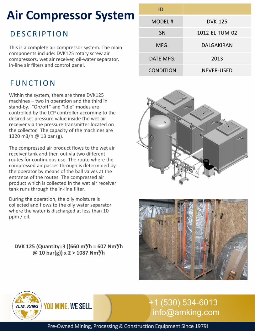
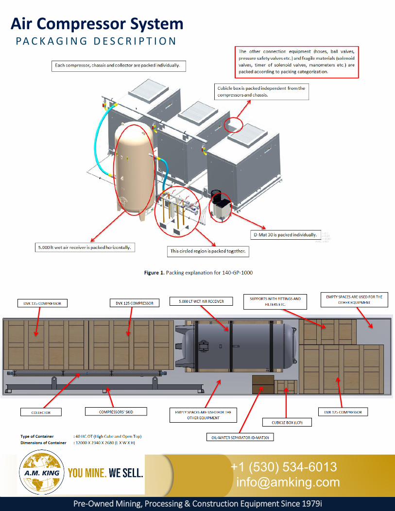
This is a complete air compressor system. The main components include: DVK125 rotary screw air compressors, wet air receiver, oil-water separator, in-line air filters and control panel.
Within the system, there are three DVK125 machines – two in operation and the third in stand-by. “On/off” and “idle” modes are controlled by the LCP controller according to the desired set pressure value inside the wet air receiver via the pressure transmitter located on the collector. The capacity of the machines are 1320 m3/h @ 13 bar (g).
The compressed air product flows to the wet air receiver tank and then out via two different routes for continuous use. The route where the compressed air passes through is determined by the operator by means of the ball valves at the entrance of the routes. The compressed air product which is collected in the wet air receiver tank runs through the in-line filter.
During the operation, the oily moisture is collected and flows to the oily water separator where the water is discharged at less than 10 ppm / oil.
F U N C T I O N
DVK 125 (Quantity=3 )(660 m³/h = 607 Nm³/h @ 10 bar(g)) x 2 > 1087 Nm³/h
Pre-Owned Mining, Processing & Construction Equipment Since 1979i
+1 (530) [email protected]
AIR COMPRESSORS
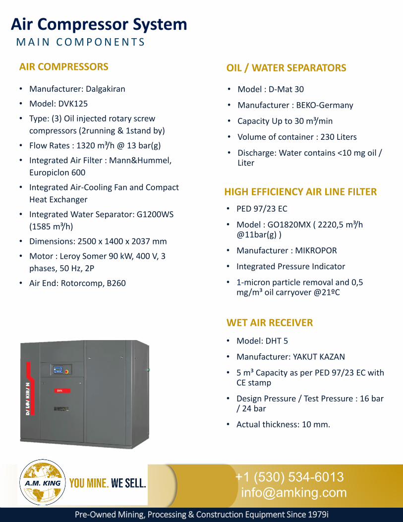
• Manufacturer: Dalgakiran
• Model: DVK125
• Type: (3) Oil injected rotary screw compressors (2running & 1stand by)
• Flow Rates : 1320 m³/h @ 13 bar(g)
• Integrated Air Filter : Mann&Hummel, Europiclon 600
• Integrated Air-Cooling Fan and Compact Heat Exchanger
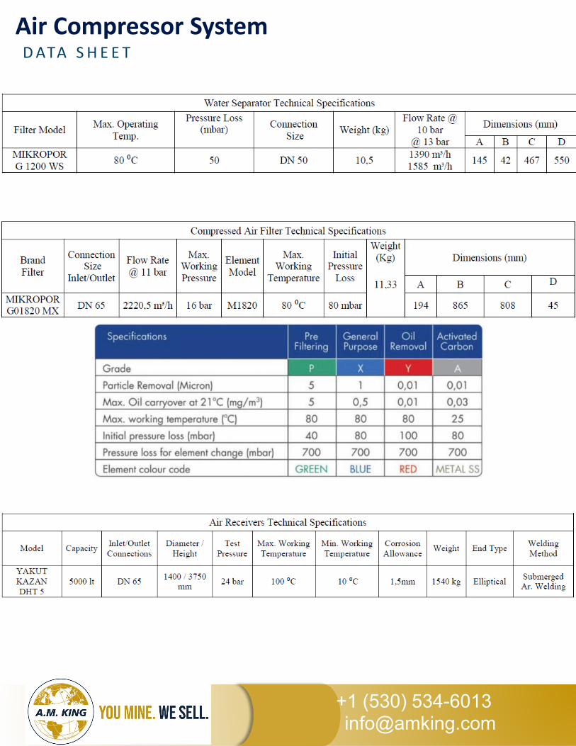
• Integrated Water Separator: G1200WS (1585 m³/h)
• Dimensions: 2500 x 1400 x 2037 mm
• Motor : Leroy Somer 90 kW, 400 V, 3 phases, 50 Hz, 2P
• Air End: Rotorcomp, B260
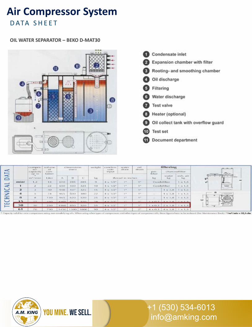
• Model : D-Mat 30
• Manufacturer : BEKO-Germany
• Capacity Up to 30 m³/min
• Volume of container : 230 Liters
• Discharge: Water contains <10 mg oil / Liter
M A I N C O M P O N E N T SAir Compressor System
• Model: DHT 5
• Manufacturer: YAKUT KAZAN
• 5 m³ Capacity as per PED 97/23 EC with CE stamp
• Design Pressure / Test Pressure : 16 bar / 24 bar
• Actual thickness: 10 mm.
• PED 97/23 EC
• Model : GO1820MX ( 2220,5 m³/h @11bar(g) )
• Manufacturer : MIKROPOR
• Integrated Pressure Indicator
• 1-micron particle removal and 0,5 mg/m³ oil carryover @21ºC
OIL / WATER SEPARATORS
WET AIR RECEIVER
HIGH EFFICIENCY AIR LINE FILTER

Pre-Owned Mining, Processing & Construction Equipment Since 1979i
+1 (530) [email protected]
P R O C E S S D E S C R I P T I O NAir Compressor System
• The electric motor of compressor (1) rotates air end unit (2).
• DALGAKIRAN compressors draw in atmospheric air through the cyclonic suction filter which is suitable for dusty environment. (4)
• Air end unit absorbs the air passing from pilot intake section of the intake valve (3) and sends it to separator tank (5) after mixing with oil. This way pressure inside separator tank (internal pressure) starts to rise.
• When the internal pressure comes to a reasonable level suction valve fully opens and compressor is loaded (20).
• Minimum pressure valve (7) does not send the internal pressure to use until it becomes to 3 -4 bar, keeps inside separator tank.
• When internal pressure starts to exceed 3,5 - 4 bars, minimum pressure valve cannot overcome the internal pressure and air production is started by opening the way.
• Separator filter (6) atop of the separator tank separates the compressed oil / air mixture from each other.
• The separated air passes through minimum pressure valve and comes to the after cooler side of combi-cooler (air to air / oil to air)(11).

Pre-Owned Mining, Processing & Construction Equipment Since 1979i
+1 (530) [email protected]
P R O C E S S D E S C R I P T I O NAir Compressor System
The separated air passes through minimum pressure valve and comes to the after cooler side of combi-cooler (air to air / oil to air)(11).
The oil inside the separator tank comes to the thermal valve by the effect of internal pressure. Thermal valve (17) does not let the oil to flow through the cooler until the oil temperature reaches the specific value. In this case; oil goes from separator tank directly to oil filter (9) and from there to air end unit. When the oil temperature reaches the required value (71°C); thermal valve closes the line in between separator tank and oil filter. And it ensures the oil to flow into cooler side of combi-cooler (8). After cooling process, oil sent to oil filter, then, the filtered oil is again sent to screw oil inlet and lubrication cycle continues.
The oil removes approx. 85% of compression heat from screw compressors with oil injected cooling. When using a heat exchanger the heat can be extracted from the oil and used for utility.
The fan on the compressor (18) ensures the flow of cooling air absorbed from environment to cooler. The cooler is composed of two parts; one for air and one for oil. This way oil and air are separately cooled in respective sections.
The air absorbed by compressor is filtered twice. When the fan sends the cooling air into compressor, the absorbed air is cleaned by air panel filter (19). The air absorbed by air end is filtered again while passing through intake filter which is suitable for dusty environment (4).
Small quantity of oil leaks into separator filter during operation. This leakage is sent back to system by oil return line (scavenge) (10).
In order for establishing pressure safety inside separator tank, safety valve (14) provides safety for future failure situations.
The oil is supplied in the compressor by removing the oil tap (15) on compressor chassis. The old oil is discharged by discharge valve (16) under separator tank.
Pre-Owned Mining, Processing & Construction Equipment Since 1979i
+1 (530) [email protected]
PA C K A G I N G D E S C R I P T I O NAir Compressor System
Page
2 / 5
Tag number
Service
Pressure
3 x 100%
Thermal valve - As per VENDOR standard Yes
Yes - CE stamp
Oil cooler (type / quantity) - As per VENDOR standard Aluminium plates type - fanOil filters -
Differential pressureCorena S2R
Shell
1620
Note 2,3
- As per VENDOR standardAs per VENDOR standard
- As per VENDOR standard
Design m³ / h VENDOR DATA
Oil circulation
Oil brand- YES
3 x 100%
Note 2,3
Class 4
-
60% @ 5°C
Stage of compression:Speed (1st)
Casing
Materials:
Oil system:
Oil type
Oil tank / separator
Quality of air required according to NF ISO 8573-1, Juin 2010 SERVICE AIR
As per VENDOR standard
Class 4
Wet air receiver
Rotors
CONSTRUCTION DATA
Class 4
6015 to 60
53547
75% @ 47°C100% @ 35°C
13
-
-
47
1211 11
80
Maximum Normal
Pressure: Maximum Normal
Oil
Particulates
Design (mechanical)
Design (mechanical)Temperature:
Rainy fall season Other seasons
Discharge conditions:
Inlet conditions:
Temperature:bar abs 1.01
Type of compressor
DutyLocation
Hazardous area classificationGas handled
Compressor manufacturerModel -
m³ / hFlow rate capacity (at batterry limit):
1900Rotor diameter mm As per VENDOR standard 270
As per VENDOR standardrpm
12 12
20 to 62
SERVICE AIR
62
Class 4
100% @ 35°C
°C
°C°C
60% @ 5°C
80
355
bar g
% 75% @ 47°C%%
1.01
Note 1,2Note 1,21320
Vendor to confirm.
1087
Continuous
3 x DVK125
Continuous
DALGAKIRAN
Non classified
-Outdoor, under shelter
Unit 143 - 145:Service Air production-
-
Oil injected rotary screw compressor
Lubricated screw Compressor preferred
AirNon classified
140-GP-1000
-
-
bar g
bar g
°C
-
Average MaximumRelative humidity Warm season
General:
°C
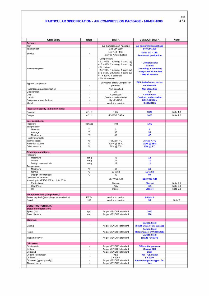
Number required -
- Compressors:- 2 x 100% (1 running, 1 stand by) or 3 x 50% (2 running, 1 stand by)- Air coolers: - 2 x 100% (1 running, 1 stand by) or 3 x 50% (2 running, 1 stand by) + 1 x 100 % in common- Wet air receiver
Item - Air Compression Package
NoteVENDOR DATA
PARTICULAR SPECIFICATION - AIR COMPRESSION PACKAGE - 140-GP-1000
CRITERIA UNIT DATA
Units 143 - 145:Service Air production
Air compression package
- Compressors:3 x 50%
(2 running, 1 stand by) - Integrated Air coolers
- Wet air receiver
140-GP-1000
Air-
Minimum °C
Nominal
Outdoor, under shelterBy VENDOR
Dew Point N/A N/A Note 2,3
-
As per VENDOR standard
As per VENDOR standardCarbon Steel
(grade P265GH)
Carbon Steel(Tradename : OVAKO 520S)
Carbon Steel(grade DD11 of EN 101111)
Note 2
Main power data (compressor):Power required @ coupling / service factor) kW / - Vendor to confirm. 86.91 / 1Rated kW Vendor to confirm. 90
Page
3 / 5
N° requiredFluid CapacityOperating pressure (gauge)Design pressure (gauge)Max allowable pressure drop 0Operating temperatureDesign temperatureDesign - Fabrication - Inspection codeStamp ASME (if any)
ManufacturerModel
Pressure loss
Design - Fabrication - Inspection code
bar g 3
Model - As per VENDOR standard G1200WS
80
- As per VENDOR standard PED 97/23/EC Note 5Purge Auto - As per VENDOR standard Effective drain
Differential pressure - As per VENDOR standard Level indicatorOil removal efficiency mg/m3 Class 4 - ISO 8573 0.5Air flow (max) m3/h As per VENDOR standard 1600Particles removal efficiency µm Class 4 - ISO 8573 1
MIKROPOR- As per VENDOR standard G1600 Mx
Number of filters - 2 x 100% 2 x 100%
Type- As per VENDOR standard
High efficiency air line filter for particles/oil removal
N° required - 3 x 100% 3 x 100%Pressure loss (max) mBar As per VENDOR standard 50Air flow (max) m3/h As per VENDOR standard 1200
Manufacturer - As per VENDOR standard MIKROPORWater separator
Up to 12
Safety pressure valve - Required YESPressure switch - Required YESIP 65 - IP 65 is acceptable as a minimum
IP65 - Pressure switch and transmitter
ATEX certification - Not required Not proposedDifferential pressure on oil filter - As per VENDOR standard YES - IndicatorLocal Control Panel - PLC by Vendor PLC - Logik 25-SLocal Gauge Boards - As per VENDOR standard Yes - Logika controlCompressor instrumentation:
ATEX certification - Not required Not proposedMain power kW - 90 Note 2Caracteristics V / - / HZ 400 V / 3 phases / 50 Hz 400 V / 3 phases / 50 Hz
Note 4
Manufacturer - As per VENDOR standardLeroy Somer (Vendor std)
Type - Electric Motor Electric MotorDriver:
Nominal air capacity m3/min As per VENDOR standard from 7.5 to 15
Free area m² As per VENDOR standard Vendor standardEfficiency (mesh %) % 1 µm 98% Vendor standard
High dusty filter - MH Europiclon 600
YES
by VENDOR
Air cooling fanIntegrated compact heat
exchanger
15 to 62100
2
Not required
Up to 20bar g
°C
-
Non-lubricated Non - Lubricated
Intake filter:
Common single lift base plate YESAnchor bolts As per VENDOR standard
20 to 62
m3
bar g
As per VENDOR standard
YESYES
°C
mBar As per VENDOR standard
-
21112
As per VENDOR standard
ASME VIII div 1 preferred80
Shaft seals:Type
Type -Dust collector -
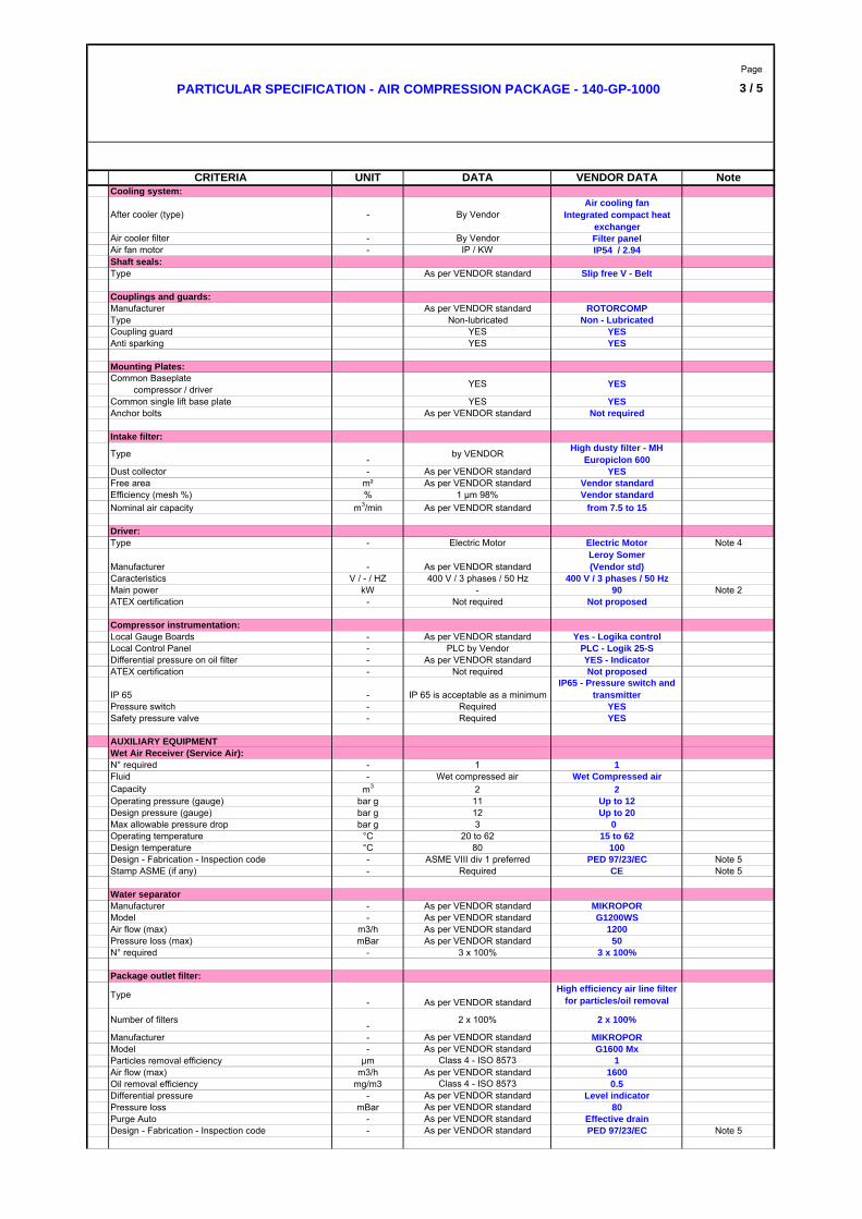
Package outlet filter:
-
As per VENDOR standard
Air cooler filterAir fan motor -
After cooler (type)
Cooling system:
-
CRITERIA UNIT DATA
Anti sparking
Couplings and guards:
Coupling guardTypeManufacturer
As per VENDOR standard
Wet Air Receiver (Service Air):AUXILIARY EQUIPMENT
Mounting Plates:Common Baseplate. compressor / driver YESYES
YES
YES
Required
Filter panel
PARTICULAR SPECIFICATION - AIR COMPRESSION PACKAGE - 140-GP-1000
By VendorIP / KW IP54 / 2.94
Slip free V - Belt
By Vendor
ROTORCOMP
YES
Note 5CE-
- 1- Wet compressed air
1Wet Compressed air
VENDOR DATA Note
PED 97/23/EC Note 5
Page
4 / 5
Electrical cable type (interconnecting cables)
Electrical cable trays type
Outlet flange - DQ01 ASME B16.5 / RF / 150# ASME B16.5 / RF / 150# Note 9
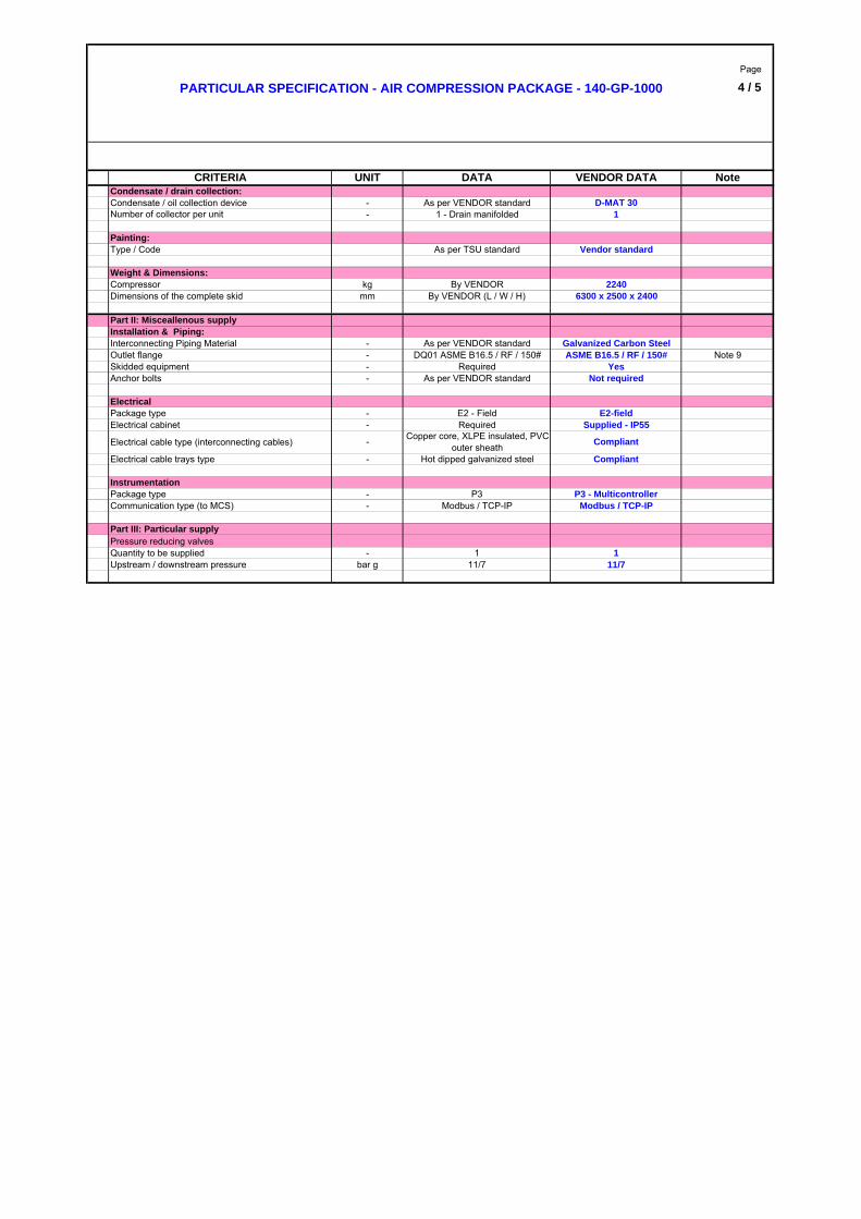
Number of collector per unit - 1 - Drain manifolded 1Condensate / oil collection device - As per VENDOR standard D-MAT 30Condensate / drain collection:
Pressure reducing valvesPart III: Particular supply
- Copper core, XLPE insulated, PVC outer sheath
- Hot dipped galvanized steel
Weight & Dimensions:
Skidded equipment - RequiredAnchor bolts -
Upstream / downstream pressure bar g 11/71
YesNot required
CRITERIA UNIT DATA
Compressor
Package type - E2 - Field E2-fieldElectrical
Galvanized Carbon Steel
Dimensions of the complete skid mm By VENDOR (L / W / H) 6300 x 2500 x 2400
Part II: Misceallenous supply
Interconnecting Piping Material - As per VENDOR standard
11/71Quantity to be supplied -
As per VENDOR standard
kg
Installation & Piping:
Painting:
Electrical cabinet - Required
By VENDOR
Type / Code As per TSU standard Vendor standard
Compliant
Compliant
Supplied - IP55
2240
Instrumentation
Communication type (to MCS) - Modbus / TCP-IP Modbus / TCP-IPPackage type - P3 P3 - Multicontroller
PARTICULAR SPECIFICATION - AIR COMPRESSION PACKAGE - 140-GP-1000
VENDOR DATA Note

Page
4 / 5
Note 2 : Performance Requirements and Guarantees for the Package:
Note 3: The quality of air required is defined according to NF ISO 8573-1, Juin 2010
Note 4: Motor shall be protected against too repetitive start-ups
Note 5: 97/23/EC PED is acceptable for design code for pressure vessel (compliant with the VENDOR standard)
Note 6: Each drying unit shall be double body (one in adsorption, one in regeneration)
Note 8: Regeneration performed by dry air from the dryer outlet (Approx 20% of total flow rate is used for dryer regeneration). Air used for regeneration shall be exhausted to the atmosphere
Note 9: Piping battery limit connections for the Package are:
Tie-in points
ref.Rating Material
(*) 150# CS Galvanized(*) 150# CS Galvanized
(*) 150# CS
* To be defined by VENDOR
Note 1: Flowrate capacity (m3/h) at theBatterry limit / outlet of the package are as per the ISO1217 requirements and are including dryers air regenration (20% air flow estimated)
Performance Requirements and Guarantees: Values Tolerances
UNIT
Outlet - Unit 145 DA01 (*) RF
Nominal 1087 m³/h - 0%Air discharge pressure
1.5 mm
+ 0%+ 0%
PARTICULAR SPECIFICATION - AIR COMPRESSION PACKAGE - 140-GP-1000
Quality of air : Service AirMaximum outlet temperature 60°C
11/ 7 bar g
Particulates Class 4 + 0% Dew Point N/A + 0%
+ 0%Electrical power consumption (absorbed power @ normal / design conditions) 90 per compressor + 0%
Dew Point (under pressure)
--
Oil (total oil concentration, at 20°C and 100 kPa) (in
mg/m3)
Class 4
Outlet - Unit 143 DA01 (*)
Note 7: Afterfilters with valving for maintenace shall be installed downstream the 2 drying units to provide final cleaning of the dry air stream by removing solid particles from the dryer desiccant
+0 dB(A)
Particulates (nb of particulates/m3 according to particulates size)
Class 40,1 μm < d ≤ 0,5 μm : Not specified0,5 μm < d ≤ 1,0 μm : Not specified
1,0 μm < d ≤ 5,0 μm : ≤ 10 000
SERVICE AIR
VENDOR DATA NoteDATACRITERIA
Noise level @ rated conditions 85 dB(A) @ 1 m
Oil Class 4
RF
Project piping class Size Finish
≤ 5
Drain Oily Water (to collector) DA01 (*) RF
SIMPLIFIED PROCESS FLOW DIAGRAM
Notes :
Corrosion allowance
1.5 mm
1.5 mm
Air Compressors
AIR
Air Coolers
140-GP-1000
SERVICE AIR
Wet air receiver
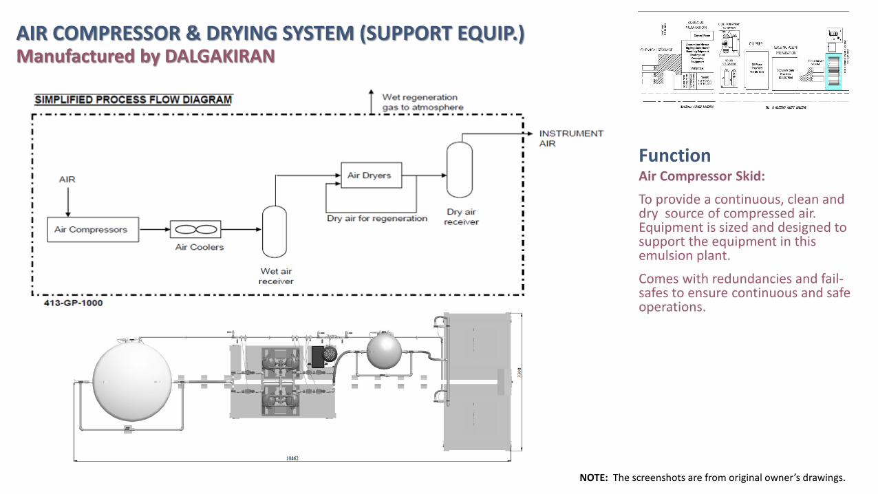
FunctionAir Compressor Skid:
To provide a continuous, clean and dry source of compressed air. Equipment is sized and designed to support the equipment in this emulsion plant.
Comes with redundancies and fail-safes to ensure continuous and safe operations.
AIR COMPRESSOR & DRYING SYSTEM (SUPPORT EQUIP.) Manufactured by DALGAKIRAN
NOTE: The screenshots are from original owner’s drawings.
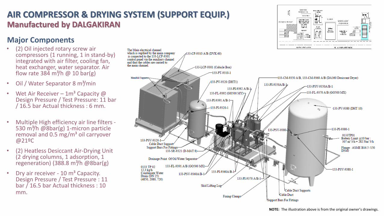
Major Components
NOTE: The illustration above is from the original owner’s drawings.
• (2) Oil injected rotary screw air compressors (1 running, 1 in stand-by) integrated with air filter, cooling fan, heat exchanger, water separator. Air flow rate 384 m³/h @ 10 bar(g)
• Oil / Water Separator 8 m³/min
• Wet Air Receiver – 1m³ Capacity @ Design Pressure / Test Pressure: 11 bar / 16.5 bar Actual thickness : 6 mm.
• Multiple High efficiency air line filters -530 m³/h @8bar(g) 1-micron particle removal and 0.5 mg/m³ oil carryover @21ºC
• (2) Heatless Desiccant Air-Drying Unit (2 drying columns, 1 adsorption, 1 regeneration) (388.8 m³/h @8bar(g)
• Dry air receiver - 10 m³ Capacity. Design Pressure / Test Pressure : 11 bar / 16.5 bar Actual thickness : 10 mm.
AIR COMPRESSOR & DRYING SYSTEM (SUPPORT EQUIP.) Manufactured by DALGAKIRAN