AII37921 2008 civic 4dr sports suspension · SPORT SUSPENSION P/N 08W60-SNX-100 PARTS LIST Right...
9
© 2007 American Honda Motor Co., Inc. - All Rights Reserved. AII 37921 (0710) 1 of 9 08W60-SVA-1000-91 INSTALLATION INSTRUCTIONS Accessory Application Publications No. Issue Date OCT 2007 2007-2008 CIVIC 4-DOOR Si SPORT SUSPENSION P/N 08W60-SNX-100 PARTS LIST Right front damper assembly Left front damper assembly 2 Rear dampers 2 Rear springs 4 Flange bolts, 14 x 57 mm 2 Flange bolts, 12 x 98 mm 2 Flange bolts, 12 x 65 mm 4 Self-locking nuts, 14 mm 2 Self-locking nuts, 12 mm (not used) 2 Self-locking nuts, 10 mm 4 Flange bolts, 12 x 54 mm Important information AII 37921 www.collegehillshonda.com
Transcript of AII37921 2008 civic 4dr sports suspension · SPORT SUSPENSION P/N 08W60-SNX-100 PARTS LIST Right...

© 2007 American Honda Motor Co., Inc. - All Rights Reserved. AII 37921 (0710) 1 of 908W60-SVA-1000-91
INSTALLATIONINSTRUCTIONS
Accessory Application Publications No.
Issue Date
OCT 2007
2007-2008 CIVIC4-DOOR Si
SPORT SUSPENSIONP/N 08W60-SNX-100
PARTS LIST
Right front damper assembly
Left front damper assembly
2 Rear dampers
2 Rear springs
4 Flange bolts, 14 x 57 mm
2 Flange bolts, 12 x 98 mm
2 Flange bolts, 12 x 65 mm
4 Self-locking nuts, 14 mm
2 Self-locking nuts, 12 mm(not used)
2 Self-locking nuts, 10 mm
4 Flange bolts, 12 x 54 mm
Important information
AII 37921
www.collegehillshonda.com
2 of 9 AII 37921 (0710) © 2007 American Honda Motor Co., Inc. - All Rights Reserved.
TOOLS AND SUPPLIES REQUIRED
10 mm and 12 mm Combination wrenches
17 mm and 19 mm Sockets
Ratchet
Torque wrench
KTC trim tool set (SOJATP2014)
5 mm Hex wrench
Needle-nose pliers
Floor jack
INSTALLATION
Customer Information: The information in thisinstallation instruction is intended for use only byskilled technicians who have the proper tools,equipment, and training to correctly and safely addequipment to your vehicle.These procedures shouldnot be attempted by "do-it-yourselfers."
NOTE:
• Inflate the tires to the specified air pressure.
• The dampers for the left and right sides aredifferent. The damper marked R goes on the rightside; the damper marked L goes on the left side.
• These dampers are designed to be usedexclusively with this model and should not be usedwith other models.
• These instructions show the left damper assemblybeing installed; the same procedure applies toinstalling the right damper assembly.
DAMPERPINCHBOLTSSELF-
LOCKINGNUTS
Removing the Front Damper
1. With the vehicle on a rack, remove all four wheels.
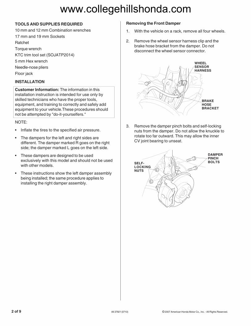
2. Remove the wheel sensor harness clip and thebrake hose bracket from the damper. Do notdisconnect the wheel sensor connector.
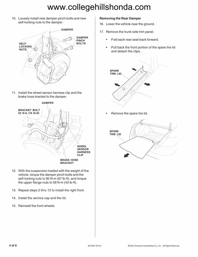
3. Remove the damper pinch bolts and self-lockingnuts from the damper. Do not allow the knuckle torotate too far outward. This may allow the innerCV joint bearing to unseat.
WHEELSENSORHARNESS
BRAKEHOSEBRACKET
www.collegehillshonda.com

© 2007 American Honda Motor Co., Inc. - All Rights Reserved. AII 37921 (0710) 3 of 9
SERVICECAP
LID
FLANGENUTS(Reuse.)
SERVICECAP
LID
FLANGENUTS(reused)
DAMPERASSEMBLY
FRONT
6. Remove the three flange nuts from top of thedamper.
7. Remove the damper assembly. Be careful not todamage the body.
DAMPERASSEMBLY
4. Turn the ignition switch ON (II), then turn on thewipers. Turn the ignition switch off when thewipers are near the A-pillars.
5. Remove the service cap and the lid.
Installing the Front Damper
8. Install the new left front damper assembly ontothe frame.
9. Loosely install the flange nuts you removed instep 6.
www.collegehillshonda.com
4 of 9 AII 37921 (0710) © 2007 American Honda Motor Co., Inc. - All Rights Reserved.
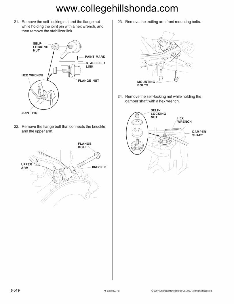
11. Install the wheel sensor harness clip and thebrake hose bracket to the damper.
12. With the suspension loaded with the weight of thevehicle, torque the damper pinch bolts and theself-locking nuts to 90 N·m (67 lb-ft), and torquethe upper flange nuts to 59 N·m (43 lb-ft).
13. Repeat steps 2 thru 12 to install the right front.
14. Install the service cap and the lid.
15. Reinstall the front wheels.
Removing the Rear Damper
• Remove the spare tire lid.
16. Lower the vehicle near the ground.
17. Remove the trunk side trim panel.
• Fold each rear seat-back forward.
• Pull back the front portion of the spare tire lidand detach the clips.
SPARETIRE LID
SPARETIRE LID
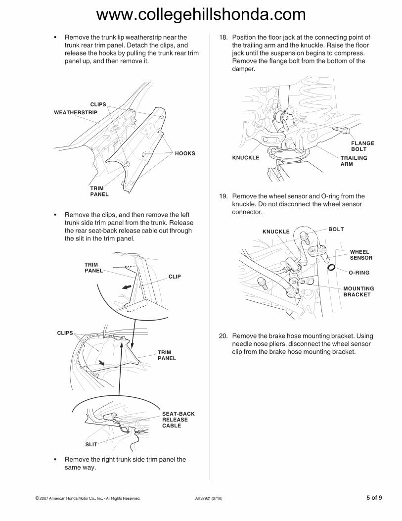
DAMPER
DAMPERPINCHBOLTSSELF-
LOCKINGNUTS
10. Loosely install new damper pinch bolts and newself-locking nuts to the damper.
DAMPER
BRACKET BOLT22 N·m (16 lb-ft)
WHEELSENSORHARNESSCLIP
BRAKE HOSEBRACKET
www.collegehillshonda.com
© 2007 American Honda Motor Co., Inc. - All Rights Reserved. AII 37921 (0710) 5 of 9
19. Remove the wheel sensor and O-ring from theknuckle. Do not disconnect the wheel sensorconnector.
• Remove the trunk lip weatherstrip near thetrunk rear trim panel. Detach the clips, andrelease the hooks by pulling the trunk rear trimpanel up, and then remove it.
18. Position the floor jack at the connecting point ofthe trailing arm and the knuckle. Raise the floorjack until the suspension begins to compress.Remove the flange bolt from the bottom of thedamper.
FLANGEBOLT
TRAILINGARM
KNUCKLE
BOLT
WHEELSENSOR
O-RING
KNUCKLE
MOUNTINGBRACKET
TRIMPANEL
HOOKS
CLIPS
• Remove the right trunk side trim panel thesame way.
TRIMPANEL
CLIP
TRIMPANEL
CLIPS
SEAT-BACKRELEASECABLE
SLIT
• Remove the clips, and then remove the lefttrunk side trim panel from the trunk. Releasethe rear seat-back release cable out throughthe slit in the trim panel.
WEATHERSTRIP
20. Remove the brake hose mounting bracket. Usingneedle nose pliers, disconnect the wheel sensorclip from the brake hose mounting bracket.
www.collegehillshonda.com
6 of 9 AII 37921 (0710) © 2007 American Honda Motor Co., Inc. - All Rights Reserved.
SELF-LOCKINGNUT HEX
WRENCH
DAMPERSHAFT
24. Remove the self-locking nut while holding thedamper shaft with a hex wrench.
23. Remove the trailing arm front mounting bolts.
MOUNTINGBOLTS
22. Remove the flange bolt that connects the knuckleand the upper arm.
21. Remove the self-locking nut and the flange nutwhile holding the joint pin with a hex wrench, andthen remove the stabilizer link.
FLANGEBOLT
KNUCKLEUPPERARM
PAINT MARK
FLANGE NUT
HEX WRENCH
JOINT PIN
SELF-LOCKINGNUT
STABILIZERLINK
www.collegehillshonda.com

© 2007 American Honda Motor Co., Inc. - All Rights Reserved. AII 37921 (0710) 7 of 9
25. Compress the damper unit by hand, and remove itfrom the vehicle.
26. Lower the floor jack gradually.
27. First remove the spring mounting rubber, and thenremove the spring and lower spring seat.
Installing the Rear Damper and Spring
28. Install the spring mounting rubber, the new spring,and the lower spring seat.
29. Align the bottom of the spring and the lower springseat with the trailing arm as shown.
SPRINGMOUNTINGRUBBER
SPRING
LOWERSPRINGSEAT
SPRINGMOUNTINGRUBBER
SPRING
LOWERSPRINGSEAT
DAMPER
TRAILINGARM
SPRING
LOWERSPRINGSEAT
www.collegehillshonda.com
8 of 9 AII 37921 (0710) © 2007 American Honda Motor Co., Inc. - All Rights Reserved.
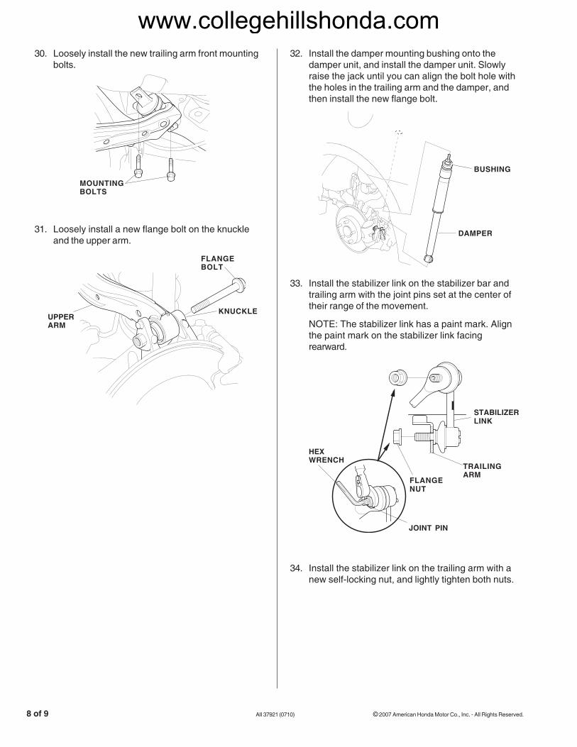
30. Loosely install the new trailing arm front mountingbolts.
31. Loosely install a new flange bolt on the knuckleand the upper arm.
32. Install the damper mounting bushing onto thedamper unit, and install the damper unit. Slowlyraise the jack until you can align the bolt hole withthe holes in the trailing arm and the damper, andthen install the new flange bolt.
33. Install the stabilizer link on the stabilizer bar andtrailing arm with the joint pins set at the center oftheir range of the movement.
NOTE: The stabilizer link has a paint mark. Alignthe paint mark on the stabilizer link facingrearward.
FLANGENUT
JOINT PIN
HEXWRENCH
STABILIZERLINK
TRAILINGARM
BUSHING
DAMPER
34. Install the stabilizer link on the trailing arm with anew self-locking nut, and lightly tighten both nuts.
MOUNTINGBOLTS
FLANGEBOLT
KNUCKLEUPPERARM
www.collegehillshonda.com
© 2007 American Honda Motor Co., Inc. - All Rights Reserved. AII 37921 (0710) 9 of 9
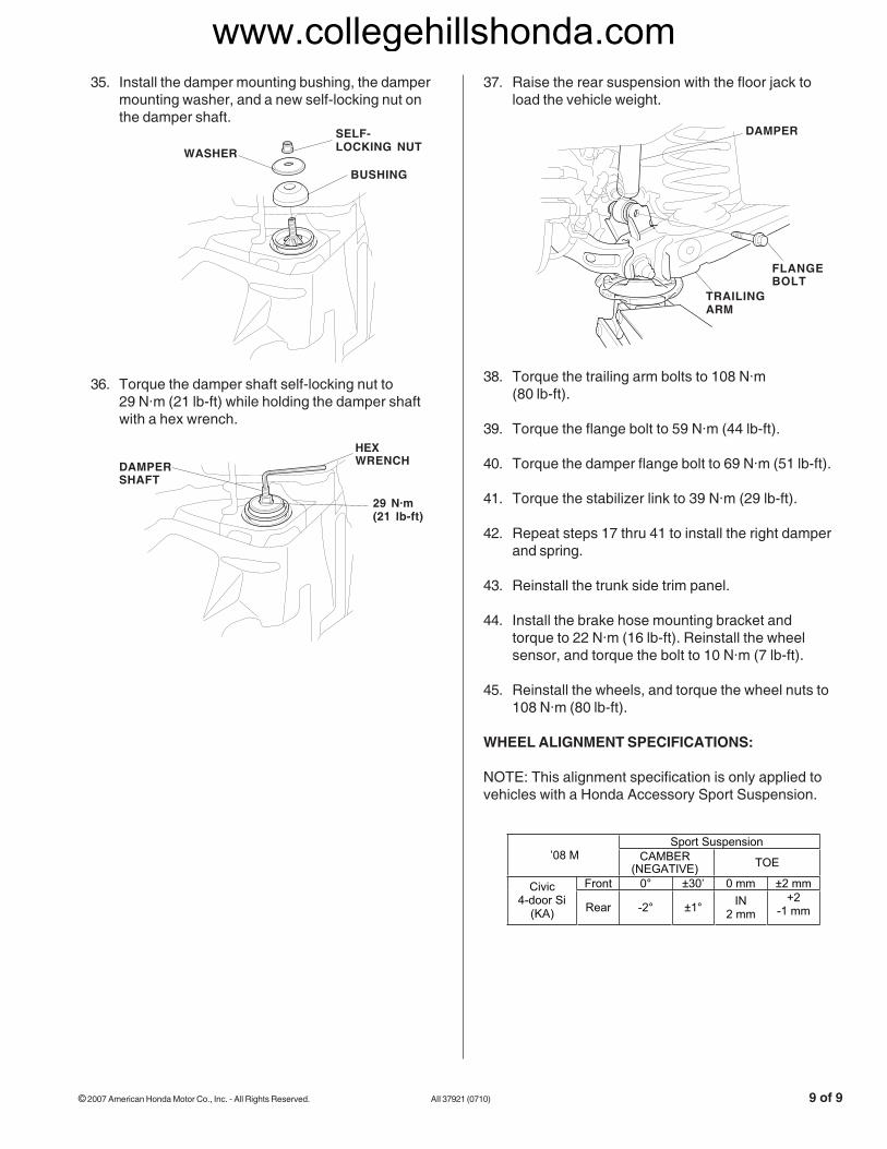
35. Install the damper mounting bushing, the dampermounting washer, and a new self-locking nut onthe damper shaft.
36. Torque the damper shaft self-locking nut to29 N·m (21 lb-ft) while holding the damper shaftwith a hex wrench.
37. Raise the rear suspension with the floor jack toload the vehicle weight.
38. Torque the trailing arm bolts to 108 N·m(80 lb-ft).
39. Torque the flange bolt to 59 N·m (44 lb-ft).
40. Torque the damper flange bolt to 69 N·m (51 lb-ft).
41. Torque the stabilizer link to 39 N·m (29 lb-ft).
42. Repeat steps 17 thru 41 to install the right damperand spring.
43. Reinstall the trunk side trim panel.
44. Install the brake hose mounting bracket andtorque to 22 N·m (16 lb-ft). Reinstall the wheelsensor, and torque the bolt to 10 N·m (7 lb-ft).
45. Reinstall the wheels, and torque the wheel nuts to108 N·m (80 lb-ft).
WHEEL ALIGNMENT SPECIFICATIONS:
NOTE: This alignment specification is only applied tovehicles with a Honda Accessory Sport Suspension.
HEXWRENCHDAMPER
SHAFT
DAMPER
TRAILINGARM
FLANGEBOLT
SELF-LOCKING NUTWASHER
BUSHING
29 N·m(21 lb-ft)
Sport Suspension ’08 M CAMBER
(NEGATIVE) TOE
Front 0° ±30’ 0 mm ±2 mm Civic4-door Si
(KA) Rear -2° ±1° IN2 mm
+2-1 mm
www.collegehillshonda.com