
AIAA-82-0406 The Feasibility of Turnback from a Low ... · AIAA-82-0406 The Feasibility of Turnback...
29
AIAA-82-0406 The Feasibility of Turnback from a Low Altitude Engine Failure During the Take- off Climb-out Phase Brent W. Jett † Aerospace Engineering Department U.S. Naval AcademyAnnapolis, MD 21402 AIAA 20th Aerospace Sciences Meeting 50th Anniversary Celebration January 11-14, 1982 Orlando, Florida † Midshipman 1/c (presently CAPT USN, Astronaut) Advisor: Dr. David F. Rogers 1
Transcript of AIAA-82-0406 The Feasibility of Turnback from a Low ... · AIAA-82-0406 The Feasibility of Turnback...

AIAA-82-0406
The Feasibility of Turnback from a LowAltitude Engine Failure During the Take-off Climb-out Phase
Brent W. Jett†Aerospace Engineering Department
U.S. Naval AcademyAnnapolis, MD 21402
AIAA 20th Aerospace Sciences Meeting50th Anniversary Celebration
January 11-14, 1982Orlando, Florida
†Midshipman 1/c (presently CAPT USN, Astronaut)Advisor: Dr. David F. Rogers
1

Abstract
Engine failure in a single engine aircraft at a low altitude is a critical evolution which de-mands immediate implementation of established procedures. The purpose of this study isto evaluate the feasibility of executing a 180◦ turn and forced landing when engine failureoccurs at 500 ft. following takeoff and transition to the climb-out phase of the flight. Usinga variable stability flight simulator set for the performance of a light single engine aircraftand a computer-controlled automatic data acquisition system, various procedures for turningback to the airfield and landing were tested and optimized. Pilots ranging in experience fromstudents with 40 hours, to FAA certified flight instructors, to veteran military pilots withmore than 5000 hours were tested in the simulator controlled circumstances. The computer-controlled data acquisition system continually recorded the critical parameters of the flightand later processed the data for analysis. The final computer output consisted of eightgraphs (airspeed, rate of climb, angle of attack, and bank angle vs time and altitude) andfour different views of a graphic computer drawing of the actual flight path. With a database of 28 pilots, an analysis of the processed output revealed that it is feasible to turn alight single engine aircraft 180◦ from 500 ft. and land the aircraft somewhere on the airfield.The data also show that the theoretical optimum bank of 45◦ with coordinated rudder doesindeed turn the aircraft 180◦ with the least loss of altitude. However, the study also showsthat 30◦ of bank with coordinated rudder produces only slightly inferior results with a muchhigher safety factor.
2

Nomenclature
AR aspect ratiob wing spanCD total drag coefficientCD0 drag coefficient at zero liftCL lift coefficientCe rolling moment coefficientCm pitching moment coefficientCn yawing moment coefficientD drage efficiency factorFc centripetal accelerationg gravitational accelerationh altitudeIxx roll moment of inertiaIyy pitch moment of inertiaIzz yaw moment of inertiak 1/πAReL liftMAC mean aerodynamic chordp roll rateq pitch rater yaw rateS wing areat timeV true airspeedY inertial coordinate systemy aircraft coordinate systemW weightZ inertial coordinate systemz aircraft coordinate systemα angle of attackβ side slip angleδa aileron deflectionδe elevator deflectionδF flap deflectionδr rudder deflectionθ pitch angleφ roll angleΨ yaw angleρ density
3

Introduction
The loss of power in a light single engine aircraft is a critical evolution under any circum-stances. Moreover, when the engine failure occurs at a low altitude during the takeoff/climb-out phase of the flight, the pilot must respond immediately with the correct procedures inorder to increase the probability of a successful emergency landing. When this type of emer-gency occurs, the current FAA approved procedures, as taught by certified flight instructors,call for the pilot to establish a glide at the velocity for maximum L/D and then attempt torestart the engine. If restart is unsuccessful, the pilot is to continue the glide straight aheadto a forced landing.
Time is one critical factor which distinguishes this emergency from engine failure at ahigher altitude. At a higher altitude, the pilot has time to diagnose the problem and toattempt to restart the engine. If restart is unsuccessful, the pilot has time and altitude toselect a suitable landing area and maneuver into an acceptable approach pattern. When en-gine failure occurs during climb-out at a low altitude (say 500 ft. above ground level (AGL)),the pilot has very little time to attempt to restart the engine and a very limited selectionof landing areas if currently approved emergency procedures are followed. The problem of asuitable landing area can become critical if the airfield is surrounded by buildings, houses,woods or water. In fact, there are many airports in the United States where the only cleararea in the vicinity of the end of the runway is the airfield itself. When emergency occursat night, it does not matter how much clear area there is around the airfield if the pilotcan’t identify it until he is too low and already committed to a specific area. The purposeof the paper, then, is to propose and determine the feasibility of an alternative emergencyprocedure for engine failure at a low altitude during the takeoff/climb-out phase of the flight.The proposed procedure is to execute a 180◦ turn back to the vicinity of the airfield.
Basically, the formulation of this procedure involves finding the optimum bank angleand airspeed for the 180◦ turn back to the airfield. This can be found by applying aerody-namic principles to a steady state power-off gliding turn. The feasibility of the maneuveris investigated by testing a wide range of pilots under controlled conditions using a variablestability flight simulator. The theoretical optimum bank angle and airspeed can also be veri-fied experimentally. Data is acquired in real time during the test flights using an automated,computer controlled, data acquisition system. The combination of theoretical analysis andexperimental data yields an optimum procedure for turnback to the airfield and shows thata maneuver is within the capability of a typical private pilot.
Theory
The optimum bank angle and airspeed for turnback are those which correspond to theminimum altitude loss in a steady state gliding turn to a new heading (Refs. 1 and 4).When engine failure occurs, drag begins to slow the aircraft. If the pilot trys to maintainaltitude by increasing the angle of attack, α, the stall speed of the aircraft will soon bereached and the pilot will then be forced to trade altitude for airspeed to keep the airplaneflying. The optimum airspeed for maximum distance in a level glide power off is not the stallspeed but rather the airspeed which corresponds to L/DMAX. The point is that the aircraftmust expend potential energy to overcome drag. In a banked turn, the lift is inclined at
4

the bank angle, φ, (Fig.l). The aircraft now requires more lift to maintain steady stateconditions. From Fig. 1 we have
L cos φ =1
2ρV 2SCL cosφ = W (1)
Therefore, the pilot must increase the velocity of the aircraft by expending potential energy(altitude) at a greater rate. The greater the bank angle in a steady state gliding turn, thegreater the rate of descent necessary to maintain steady state conditions while in the turn.Thus, the time in the turn plays an important role in finding the optimum bank angle andairspeed.
From Fig. 1 we have
Fc = L sin φ =V 2
R
W
g(2)
Combining equations (1) and (2) yields
F =V 2
gtanφ(3)
Now the time required for the aircraft to turn through the angle Ψ is
t =Ψ
Ψ̇(4)
for a steady state turn
Ψ̇ =dΨ
dt=
V
R=
Ψ
t(5)
-Y +Y
-Z
+Z
+z
+y
-y
L
W
Fc
Figure 1. Forces in the yz plane acting on an aircraft in a steady state gliding turn.
5

The rate at which the aircraft is losing potential energy (altitude) must be equal to therate at which energy is being expended to overcome drag. Thus,
Wdh
dt= DV (6)
For steady state conditions
Wh
t= DV (7)
which may be written as
h =D
WV t (8)
Combining with equations (3) and (5) yields
h =(DV
W
)V
g
Ψ
tan φ(9)
Noting thatD
W=
CD
CLcos φ
and
V 2 =2W
ρSCL cosφ
equation (9) becomes
h =
[CD
C2L
2W
ρSg
1
cosφ sinφ
]Ψ (10)
Differentiation with respect to Ψ yields the conditions for minimum loss of altitude withheading change
dh
dΨ=
CD
C2L
2W
ρSg sinφ cos φ(11)
Noting thatsin2φ = 2 sinφ cos φ
equation (11) becomesdh
dΨ=
CD
C2L
4W
ρSg sinφ(12)
Examining each term, we note that for a parabolic drag polar
CD = CD0 + kC2L (13)
andCD
C2L
=CD0
C2L
= k (14)
which is a minimum at maximum CL. Thus, the airspeed for minimum loss of altitudeoccurs at C2
LMAXor the stall speed. For a given altitude, the second term, 4W/ρSg sin 2φ, is
6

10
0
20
30
40
50
60P
er c
ent
of p
ilots
< 100 100 - 200 > 200Hrs Hrs Hrs
Figure 2. Total flight hours of the test pilots.
a minimum when sin 2φ = 1 or φ = 45◦. Thus, the bank angle for minimum loss of altitudeis 45◦.
The effect of flaps on this maneuver will depend upon the aircraft being flown. Theincreased lift and drag which occur with flap deflection will effect the CD/C2
L term of equa-tion (12). For the simulator used in the test flights, flap deflection results in a very slightincrease in CD/C2
L. However, this increase is so small that the effect of flap deflection canbe considered negligble.
10
0
20
30
40
50
60
Per
cent
of p
ilots
Student Private Commercial CFI
70
Figure 3. Highest rating achieved by the test pilots.
7
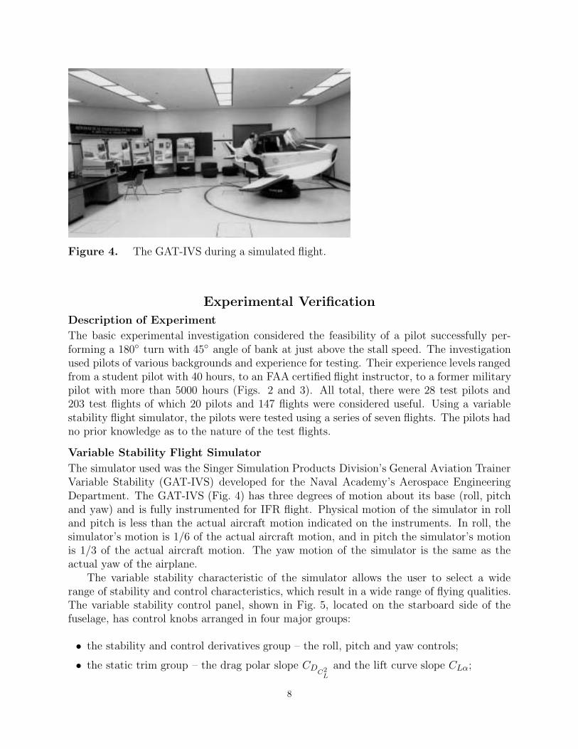
Figure 4. The GAT-IVS during a simulated flight.
Experimental Verification
Description of Experiment
The basic experimental investigation considered the feasibility of a pilot successfully per-forming a 180◦ turn with 45◦ angle of bank at just above the stall speed. The investigationused pilots of various backgrounds and experience for testing. Their experience levels rangedfrom a student pilot with 40 hours, to an FAA certified flight instructor, to a former militarypilot with more than 5000 hours (Figs. 2 and 3). All total, there were 28 test pilots and203 test flights of which 20 pilots and 147 flights were considered useful. Using a variablestability flight simulator, the pilots were tested using a series of seven flights. The pilots hadno prior knowledge as to the nature of the test flights.
Variable Stability Flight Simulator
The simulator used was the Singer Simulation Products Division’s General Aviation TrainerVariable Stability (GAT-IVS) developed for the Naval Academy’s Aerospace EngineeringDepartment. The GAT-IVS (Fig. 4) has three degrees of motion about its base (roll, pitchand yaw) and is fully instrumented for IFR flight. Physical motion of the simulator in rolland pitch is less than the actual aircraft motion indicated on the instruments. In roll, thesimulator’s motion is 1/6 of the actual aircraft motion, and in pitch the simulator’s motionis 1/3 of the actual aircraft motion. The yaw motion of the simulator is the same as theactual yaw of the airplane.
The variable stability characteristic of the simulator allows the user to select a widerange of stability and control characteristics, which result in a wide range of flying qualities.The variable stability control panel, shown in Fig. 5, located on the starboard side of thefuselage, has control knobs arranged in four major groups:
• the stability and control derivatives group – the roll, pitch and yaw controls;
• the static trim group – the drag polar slope CDC2
L
and the lift curve slope CLα;
8

Table I
GAT-IVS Standard Flight Parameters
Stability derivatives
Pitch Static trimCMCL
= −0.314 CDC2
L
= 0.060
CMq = −0.0928 slug sec/ft2 CD0 = 0.034Cnδe
= −0.900 CLα = 4.412 rad−1
Roll Moments of InertiaC�β = −0.1014 rad−1 Ixx = 870 slug ft2
C�ρ = −0.00481 slug sec/ft2 Iyy = 1147 slug ft2
C� = −0.0260 Izz = 1700 slug ft2
Yaw Other ParametersCnβ
= 0.0751 rad−1 S = 157 ft2
Cnr = 0.00198 slug sec/ft2 b = 32.7 ftCnδa
= 0.0024 MAC = 4.8 ftCnδr
= −0.0292 W = 1600 lbs∆CLδF
= 0.65∆CDδF
= 0.068
• the moment of inertia group – Ixx, Iyy, Izz;
• the step function control group – δe, δa, δr.
Figure 6. The GAT-IVS cockpit and instrument panel.
9

Figure 5. The GAT-IVS variable stability control panel.
The basic GAT-IVS settings were used for the experiment and are listed in Table I alongwith other basic flight parameter values (Ref. 3). The basic GAT-IVS settings result inthe simulator approximating the behavior of a “single-engined, light utility/sport airplane”(Ref. 3).
The simulator cockpit (Fig. 6) is representative of a standard light single engine aircraft.During the experiment, the simulator was set for a fixed pitch, fixed gear aircraft. Thepilots were not required to use any communications equipment during the experiment. Allinstructions were issued directly to the pilot.
The instructor control panel (Fig. 7). located on the starboard side of the GAT-IVSallows the experimentor to control various aircraft and environmental parameters. Thestandard settings were used and are listed in Table II (Ref. 3). Notice that the instructorcontrol panel contains the engine failure switch. Figure 8 shows the physical location of bothcontrol panels.
10

Figure 7. The GAT-IVS instructor control panel.
Data Acquisition System
The computer system used to record, process and display the simulator flight test dataconsisted of the following (Fig. 9):
a Tektronix 4051 Computer Graphics System with 32K memory;
a Tektronix 4907 File Manager;
a Tektronix 4051 #01 ROM Expander;
a Tektronix 4631 copier.
The 4051’s capabilities were enhanced by using four Read Only Memory (ROM) modules,which incorporated various additional features. A Transera data acquisition ROM modulecontained the analog to digital conversion capability necessary to record the flight parametersof the simulator in real time. A real time clock and all the matrix multiplication routinesrequired for graphic displays were contained in two other ROM modules. The fourth ROMmodule was exclusively for manipulating and managing data files on the 4907.
The 4907 File Manager recorded all the flight data in real time onto a flexible discstorage device. This flexible disc also held the eight computer programs necessary for data
11

Figure 8. The GAT-IVS control panels, cockpit and instrument panel.
acquisition, processing and display. The 4631 produced copies of the graphic displays on the4051’s cathode ray tube (CRT). Figure 10 shows the complete simulator test flight and thedata acquisition system.
The Computer Programs for Data Acquisition, Processing and Display
The data acquisition computer program uses the analog to digital capability of the TranseraROM module to record 11 different flight parameters (Ref. 3 and Table III). Actually, theflight parameters correspond to 11 voltages on 11 different output channels from the simula-tor. These voltages are recorded in real time as each channel is scanned at the rate of onceper second. The data is stored in a ‘packed’ format on the disc of the 4907 File Manager.
Table II
Standard Instructor Panel Settings for GATIVS
Control/Parameter Value/PositionCenter of Gravity 25% MACGross Weight 1600 lbsOutside Air Temperature standardRough Air offBarometric Pressure 29.92 in HgWind Velocity 0 knotsWind Direction 0 degreesPitch, Roll Yaw motion onCommunications Frequency disregardEngine Controls Group normal
12

Figure 9. The computer controlled data acquisition system.
The data processing programs are completely automated and only require the user tostart the first program in the sequence. From then on, the computer automatically processesthe data from each test flight on the disc, displays each result on the 4051 CRT and copieseach display with the 4631 copier. An unlimited number of test flights can be processedwithout any manual input. The only restriction is the amount of storage space on each disc.
13

Figure 10. The simulator test flight and data acquisition system.
The first program in the processing sequence unpacks the data into a usable form. Then,another program converts the voltages recorded during the test flight into the actual flightparameters (airspeed, altitude, etc.). The conversion factors for each flight parameter wereobtained from the GAT-IVS laboratory manual and the routine was calibrated by performingseveral calibration test flights.
With the flight parameters now available, the next program in the processing sequencecalculates the flight path of the aircraft. First, a three dimensional velocity vector is calcu-lated at time tl. The position of the aircraft one second later, at time t2, is approximated byassuming a constant velocity for the entire second. Then a new three-dimensional velocityvector is calculated for time t2. The position of the aircraft one second later, at time t3, isdetermined by the same method. Since the initial position of the aircraft is known (the end
Table III
Flight Parameters Recorded From GAT-IVS
Angle of attack (α)Side slip angle (η)Pitch angle (θ)Roll angle (φ)Heading - (two channels required)Altitude (h)True airspeed (V)ThrustGear extensionFlap deflection
14

Figure 11a. Flight path drawings and digital output of a successful test flight.
FLIGHT DATA FOR F01041 8 FEB 81
DURATION OF FLIGHT: 110 SEC AIRCRAFT WEIGHT: 1600 LBSRUNWAY HEADING: 270 DEG FINAL POSITION (X): 3423 FTFIELD ELEVATION: 42 FT FINAL POSITION (2): 1423 FTMAX ALTITUDE: 481 FT(AGL) MAX AIRSPEED: 79 KNTSMAX R/C: 2648 FT/MIN MIN R/C: 1729 FT/MINMAX RIGHT BANK: 40 DEG MAX LEFT BANK: 3 DEGMAX ANGLE OF ATTACK: 14 DEG
of the runway), the entire flight path can be calculated by this method.The two display programs produce the graphic output shown in Fig. 11. After copies of
the output are automatically made by the 4631 copier, the entire sequence starts again onthe next flight waiting to be processed. Additionally, there are two manual display programswhich will produce full size (8 1/2” x 11”) displays of any graph or flight path drawing. Thetechniques used for the graphic display are detailed in Ref. 2.
Conduct of the experiment
The actual experiment was conducted in the following manner. Each pilot was given athorough briefing on the simulator and allowed to conduct a familiarization flight. The
15

Figure 11b. Graphic output of the flight parameters from a successful test flight.
testing did not begin until the pilot indicated that he felt comfortable flying the simulator.Prior to each test flight, the pilot received a standardized briefing for the particular maneuverrequired by the flight. During each flight, engine failure occurred at 500 ft. AGL, and theresults were recorded by the computer. The following are the instructions given before eachflight.
Flight #1
“The purpose of this experiment is to test procedures used by pilots in emergency situations.You are to begin this flight with a normal takeoff, a straight-out departure, and climb to3000 ft. After reaching altitude, you will receive further instructions. Sometime during the
16

flight you will experience an emergency – handle the situation using any procedure you wish.If you are ready to begin, bring the airplane to runway heading and begin your takeoff.”
Flight #2
“As you now know, the emergency situation we are studying is engine failure in a singleengine aircraft during the climb-out phase of the flight. Again, this time your engine willfail – handle the situation any way you wish. If you are ready, bring the aircraft to runwayheading and begin your takeoff.”
Flight #3
“For test flight #3, we would like for you to try the following procedure: When your enginefails, turn the aircraft 180◦ and make a simulated landing on your new heading. Your enginemay fail at any time continue in a straight-out departure until then. If you are ready, bringthe aircraft to runway heading and begin takeoff.”
Flight #4
“For test flight #4, we would like for you to try the following procedure: When your enginefails, turn the aircraft 180◦ using a coordinated 45◦ banked turn with the airspeed just abovestall and make a simulated landing on your new heading. The object is to turn the aircraftwith a minimum loss of altitude. Again, continue in a straight-out departure until yourengine fails. If you are ready, bring the aircraft to runway heading and begin takeoff.”
Flight #5
“For test flight #5, we would like for you to, when your engine fails, turn the aircraft 180◦
with 45◦ bank, full rudder, airspeed just above stall, and make a simulated landing on yournew heading. The object is still to turn the aircraft with a minimum loss of altitude.”
Flight #6
“For test flight #6, when your engine fails, turn the aircraft 180◦ with 15◦ bank, full rudder,airspeed just above stall and make a simulated landing on your new heading.”
Flight #7
“For test flight #7, when your engine fails, turn the aircraft 180◦ with 30◦ bank, coordinatedrudder, with the airspeed just above stall and make a simulated landing on your new heading.Remember the object is to turn the aircraft with a minimum loss of altitude.”
Results
The automated computer system, which analyzed the flight test data, produced as a finaloutput for each flight (Fig. 11):
17

• four graphs of airspeed, rate of climb, bank angle, and angle of attack as a function oftime;
• four graphs of airspeed, bank angle, rate of climb and angle of attack as a function oftime;
• Three orthoginal views and one 3-D isometric view of the simulator’s flight path;
• a digital print out of various flight parameters.
A full size display of any particular graph or flight path can also be obtained. All of the
Figure 12a. Flight path drawings and digital output of an unsuccessful test flight.
FLIGHT DATA FOR F01531 6 FEB 81
DURATION OF FLIGHT: 114 SEC AIRCRAFT WEIGHT: 1600 LBSRUNWAY HEADING: 270 DEG FINAL POSITION (X): 5048 FTFIELD ELEVATION: 47 FT FINAL POSITION (2): 2422 FTMAX ALTITUDE: 487 FT(AGL) MAX AIRSPEED: 73 KNTSMAX R/C: 2964 FT/MIN MIN R/C: 1946 FT/MINMAX RIGHT BANK: 4 DEG MAX LEFT BANK: 17 DECMAX ANGLE OF ATTACK: 14 DEC
18

Figure 12b. Graphic output of the flight parameters from of an unsuccessful test flight.
analysis in the subsequent section is based on this information depicted in these displays.
Analysis
The first step in the data analysis was to establish the criteria for successful conventional
19

emergency landings and for successful turnback emergency landings. The following are thecriteria used for successful conventional emergency landings:
• the maximum rate of descent during the flight must not exceed 2500 feet per minute(fpm);
• the rate of descent at touchdown must not exceed 500 fpm;
• the wings must be level (±5◦) at all altitudes below 100 ft. AGL.
The criteria for successful turnback emergency landings are the same as for the conven-tional emergency landings with the following additions:
• the pilot must complete a turn of at least 175◦ at an altitude above 100 ft. AGL;
• the maximum bank angle in the turn must be less than 55◦.
Figure 12 shows the output of an unsuccessful turnback flight. Compare this outputwith that in Fig. 11, which is from a successful turnback flight.
Test Flight 1
Recall that for this flight, the pilot was told to climb to 3000 ft. AGL and await furtherinstructions. Therefore, the engine fai1ure at 500 feet should have been totally unexpected.The data analysis shows that 17 out of the 20 pilots (85%) continued straight ahead toemergency landings. Of those that continued straight ahead, 100% of the landings weresuccessful (assuming there was a suitable place to land the aircraft). Two of the three pilotswho attempted to turnback to the airfield crashed as a result of steep bank angles and thesubsequent spin/stall. Both of these pilots have private ratings and between 100 and 200hours of total flight time. The pilot who was successful in turning back to the airfield alsohas a private rating, but has less than 100 hours total flight time. The angle of bank usedby this pilot in the turn was 40◦
An interesting observation made during the testing was that less than 50% of the pilotstried to restart the engine. One FAA certified flight instructor did not try to restart theengine; however, every pilot with military flight training did attempt a restart.
Test Flight 2
Recall that the only difference between this flight and test flight 1 is that the pilot knowshis engine will fail. The pilot who successfully turned back to the airfield in flight 1 did soagain in flight 2. The two pilots who unsuccess- fully tried to turnback in flight 1 decidedto continue straight ahead to successful emergency landings in flight 2. Again, 100% of thestraight ahead emergency landings were successful. Inter- estingly, one student pilot with 56hours of flight time attempted to turnback in flight 2 after having made a successful straightahead landing in flight 1. The attempted turnback was unsuccessful.
20

10
0
20
30
40
50
60Pe
r ce
nt o
f pilo
ts
< 100 100 - 200 > 200Hrs Hrs Hrs
12.5
45.050.0
Figure 13. Test flight 3 success rate for pilots grouped according to flight hours.
Test Flight 3
In this flight, the pilot was told to attempt a 180◦ turn and emergency landing afterengine failure. No specific procedure was specified. This type of flight could occur in a reallife situation if, after engine failure, the pilot immediately realize that there wasn’t a suitablelanding area anywhere ahead. If this happens, the pilot will be tempted to try a turnbackto the airfield. The overall percentage of successful flights was 42.86%. Figure 13 shows abreakdown of the success rate by the pilots grouped according to flight hours. As expected,the highest percentage of successful flights occured in the group of pilots with more than 200hours. Figure 14 shows the distribution of the successful flights according to the maximumbank angle used in the turn. Approximately eighty-five percent (84.62%) of the unsuccessfulflights were the result of the bank angle exceeding 55◦ and a subsequent spin/stall.
Test Flight 4
The procedure for the 180◦ turn to an emergency landing was specified in this flight asfollows:
21

10
0
20
30
40
50
60
Per
cen
t of
suc
cess
ful f
light
s
< 20
70
20-30 30-40 40-50 >50Bank angle used (degrees)
14.3
57.1
28.6
Figure 14. The distribution of successful flights according to the bank angle used.
45◦ bank with coordinated rudder;
airspeed just above stall.
The overall success rate for this flight was 75%. Figure 15 depicts the success rate for eachpilot group. As expected, the lowest success rate occured in the group of pilots with lessthan 100 hours. Of the successful flights, the average altitude lost in the turn was 339 ft.The average time in the turn was 21.1 seconds and the average rate of descent upon turncompletion was 1067 fpm.
One hundred percent of the unsuccessful flights were caused by the pilot allowing thebank angle to become too steep. This resulted in a high rate of descent and in some cases,impact while still in the turn. However, the pilots who were unsuccessful were given theopportunity to repeat the flight. Of the 25% of the pilots that failed on the first attempt,10% were successful on their second attempt and 5% were successful on the third attempt.Ten percent of the pilots were unable to perform the maneuver successfully after three
22

attempts. The two pilots who were unsuccessful after three attempts had less than 100hours and one was a student pilot.
Test Flights 5 and 6
Originally, flights 5 and 6 were designed to investigate the effect of excess rudder on thegliding turn. However, because the computer controlled acquisition system was unable torecord the rudder deflection and because the pilots did not consistently use ‘full rudder’ intheir turns, the flight data is not useful for complete analysis.
Test flight 5 required the pilot to turn the aircraft 180◦ using 45◦ bank, full rudder,with the airspeed just above stall. This maneuver was extremely difficult because it requiredthe airplane to be cross controlled with opposite aileron to prevent the bank angle fromexceeding 45◦ This flight had an overall success rate of 45%. One hundred percent of thefailures were the result of steep bank angles and the resulting spin/stall.
Flight 6 required the pilot to turn the aircraft 180◦ using 15◦ bank, full rudder, withthe airspeed just above stall. The success rate for this flight of 55% was slightly higherthan flight 5. Like the maneuver in flight 5, this maneuver required the airplane to be crosscontrolled. Consequently, the airplane developed a high rate of descent relative to the rateof turn and the failures were the result of the pilots not completing the 180◦ turn above 100ft. AGL.
Test Flight 7
This flight required the pilot to perform the 180◦ turn using the following procedure:
• 30◦ bank with coordinated rudder;
• Airspeed just above stall.
The overall success rate for this flight was 95%. Figure 16 shows the success rate for eachpilot group. The one pilot who was unsuccessful on his first attempt at the maneuver wassuccessful on his second attempt. An analysis of the first flight revealed that the reasonfor the failure was that the pilot used only 20◦ of bank instead of the 30◦ specified inthe procedure. Of the successful flights, the average altitude lost in the turn was 341 ft.The average time in the turn was 26.1 seconds and the average rate of descent upon turncompletion was 994 fpm.
Summary of Results and Analysis
Based on the analysis of the seven flights, the procedures used in test flight 4 and 7 justifyfurther comparison as both appear to be feasible procedures for turnback to the airfield.Comparing the altitude lost in the turn (Fig. 17), the experimental data supports the theorythat 45◦ bank will result in the minimum loss of altitude during the gliding turn. However,the altitude lost in the 30◦ turn is only slightly greater. A comparison of the descent rateat turn completion (Fig. 18), on the other hand, shows a slight advantage to the 30◦ banked
23

80
0
20
40
60
Per
cen
t of
flig
hts
< 100
100
100-200 >200Flight hours
Figure 15. Test flight 4 success rate for pilots grouped according to flight hours.
turn. Finally, a comparison of the success rate gives a distinct advantage to the procedurein test flight 7 (Fig. 19).
Additional Considerations
There are several other factors which must be investigated before turning back to the airfieldcan be considered feasible. In this experiment, the average time to engine failure after theinitiation of takeoff roll was 45.63 seconds. The time required to turn the airplane andland was an additional 45.74 seconds. The question that must be considered is whether ornot turning back to the airfield will endanger other airport traffic. At major airports, thepilot will have to expect to deal with landing or departing aircraft on his departure runwayand traffic on any crossing runways in use. Crossing runways may be used simultaneouslyif the conditions outlined in Section 231 of the Airmans Information Manual covering Air
24

0
20
60
40
80
100Pe
r ce
nt o
f flig
hts
< 100 100 - 200 > 200Hrs Hrs Hrs
Figure 16. Test flight 7 success rate for pilots grouped according to flight hours.
Traffic Control (ATC) procedures are met. Thus, communication with the controller wouldbe necessary to minimize the chance of an incident with other aircraft in the traffic pattern.Additionally, in a real situation, the pilot will probably elect to turn the aircraft an additional5 or 10 degrees so that after making the turn, the aircraft will be gliding back toward thedeparture runway. In the experiment, the average turn diameters for flights 4 and 7 were 1356ft. and 1519 ft. respectively. Therefore, if the pilot is unable to turn back to the reciprocal ofthe initial runway heading just before landing, the glide/landing path may cross the activerunway and its taxiways. Again, communication with the controller would be required toprevent a possible incident.
Although communication with the controller is necessary, the pilot must first establishhis turnback and airspeed before using the radio. Section 224 of the Airmans InformationManual exempts emergencies from those situations requiring the pilot to notify the controller
25

0
100
300
200
400
500A
ltitu
de lo
st in
turn
(ft)
Flight 4 Flight 7
339 341
Figure 17. A comparison of the altitude lost in a 180◦ turn for flights 4 and 7.
before performing a major unexpected maneuver. If the pilot waits until after communicationwith the tower to initiate the turn, valuable altitude and airspeed are wasted.
Conclusions
The analysis of emergency procedures for low altitude engine failure during the takeoff/climb-out phase has led to several significant conclusions. First, 15% of the pilots tested ignoredstandard procedure in Flight 1 and attempted to turnback to the airfield when engine failureoccured at 500 ft. AGL. The percentage would probably have been significantly higher ifthe pilots were told that the area outside the airfield was unsuitable for emergency landing.Only 33.3% of the attempted turnbacks in Flight 1 were succesful. However, 100% of thestraight ahead emergency landings in the same flight were successful. When told to attemptto turnback in Flight 3, only 42.86% were successful. Thus, the first signifi- cant result ofthe analysis:
26

0
1
3
2
Rat
e of
des
cent
(100
0 fp
m)
Flight 4 Flight 7
1067 994
Figure 18. A comparison of the rate of descent upon turn completion for flights 4 and 7.
Turning back to the airfield after engine failure is feasible under proper circumstances.Turning with 30◦ bank, coordinated rudder, at an airspeed slightly above stall, will yieldthe best combination of the performance and safety.The proper circumstances mentioned above incorporate several aspects of each individual
flight. First, the minimum altitude at which this maneuver can be successfully performed willvary with the type of aircraft and the pilot’s ability. Therefore, a pilot should not attemptto turn back to the airfield unless the procedure has been practiced at a safe altitude and theminimum turnback altitude for the combination of his ability and aircraft is known. Thisminimum turnback altitude should be the altitude lost in a gliding 180◦ turn from climb-outconfiguration plus 100 ft. Also, as previously stated, turnback should not be attempted ifthere is a suitable landing area ahead.
Finally, consideration of the need to communicate with the controller yields the fol-lowing sequence of events for the turnback maneuver when the circumstances dictate itsperformance:
27

0
20
60
40
80
100Su
cces
s ra
te (p
er c
ent)
Flight 4 Flight 7Figure 19. A comparison of the success rate for test flights 4 and 7.
initiate turn - establish bank angle (30◦) and airspeed (slightly above stall);
communicate intentions to controller;
Attempt to restart the engine.
Thus, the pilot who experiences engine failure during takeoff/climb-out is no longerlimited to proceeding straight ahead to a forced landing. If there is no suitable landing areaahead, the pilot who has practiced and mastered the turnback technique will immediatelyknow whether or not turning back to the airfield is possible (by the minimum turnbackaltitude) and will be able to perform the maneuver successfully.
28

References
Books
1. Dommasch, D. 0., Sherby, S. S. and Connolly, T. F., Airplane Aerodynamics, 4th ed.,Pitnam, New York, 1967.2. Rogers, D. F. and Adams, J. A., Mathematical Elements for Computer Graphics, McGrawHill, New York, 1976.
Manuals
3. Mazza, C. J., Fortenbaugh, R. A. and Piranian, A. G., Laboratory Manual: U. S. NavalAcademy Variable Stability Flight Simulator, Naval Air Development Center, Warminster,Pennsylvania, 1974.
Private Communications
4. Professor B. H. Carson, United States Naval Academy, Aerospace Engineering Depart-ment, March 1981.
29


![[20대연구소] 주간뉴스클리핑(20140331 0406)](https://static.fdocuments.net/doc/165x107/559a2bc91a28abf4758b46af/20-20140331-0406.jpg)


