Aging Aircraft Sustainment with Non-Standard Engineering
29
Aging Aircraft Sustainment with Non-Standard Engineering NDIA 10 th Annual Systems Engineering Conference Hyatt Regency Mission Bay, San Diego, CA October 22-25, 2007 Kendal Hinton 404-407-6042 [email protected] Chris Fowler 404-407-7094 [email protected]
Transcript of Aging Aircraft Sustainment with Non-Standard Engineering

GTRI_B-1
Aging Aircraft Sustainmentwith Non-Standard Engineering
NDIA 10th Annual Systems Engineering Conference Hyatt Regency Mission Bay, San Diego, CA
October 22-25, 2007
Kendal Hinton404-407-6042
Chris Fowler404-407-7094

GTRI_B-2
Evolution of Avionics Systems
FROM…
• Single-Function, stand-alone characterized by multiple subsystems
• Connected multiple analog signals using point-to-point wiring, to provide a single function
TO…
• Digital technology for information transfer
• Allowed network sharing of the physical interface
• Reduced number of interconnections within the airframe

GTRI_B-3
MIL-STD-1553• Result of a cooperative effort between the military
and industry
• Defines the electrical and protocol characteristics for a digital, serial communication standard among systems
• From its initial release in 1973, the standard has been revised and updated to reflect lessons learned from implementation.
• Currently standard version is revision B, Notice 6

GTRI_B-4
MIL-STD-1553B Notice 6
• Defines the data bus network as a a main bus cable to which stubs are attached and terminals are connected to the stubs
• Voltage waveforms arrive at different terminals with the least amount of distortion
• Major parameters affecting waveform quality are bus length, number of stubs, and locations and lengths of stubs

GTRI_B-5
A Design-to-Standard Bus
http://www.n-digital.co.jp/Milestek/diagramandtechinf/Mil1553bComp.intro.files/SVS.JPG
SYSTEMSYSTEM SYSTEM

GTRI_B-6
Non-Standard A/C 1553 WiringAnalysis
LEGACY ISSUES…
• While strides are being made to integrate avionics systems, the physical infrastructures on the target platforms may not be up to the bus standard.
• Installing wiring that conforms to the standard on any legacy system can be costly
POSSIBLE SOLUTION…
• Using non-compliant wiring installed on an aircraft, can systems reliably exchange information over the bus?
• Beneficial to derive and implement an analysis process

GTRI_B-7
Non-Standard A/C 1553 WiringAnalysis
To ensure…
• Performance
• Maintenance
• Supportability
Plan to…
• Develop Spice Models
• Execute Lab Tests
• Perform SPICE Analysis of Actual A/C Wiring
• Perform Lab Analysis of Actual A/C Wiring

GTRI_B-8
Existing A/C 1553 Wiring
RG-180
RG-180
RG-180
Matrix Assembly 2(Aft)
Wheel Well DisconnectCircular Connector
TycoConnectors
Adapter
SMAMatrix Assembly 1(Fwd)
+ - -+
F-16C+ Block Diagram
STP
EW System

GTRI_B-9
Examining Signal Quality on the Bus Network
• GOAL – To transfer voltage waveforms with minimum distortion
• To determine whether or not a network will perform reliably, its characteristics are measured and compared to the requirements of the standard.
• The quality of the waveform is determined by examining it in the following respects:
• Amplitude
• Zero-crossing distortion
• Waveform tailoff

GTRI_B-10
Test Waveform
PASS 3200
Bus Coupler
S1 S2
Bus Coupler
PASS 3200
O-SCOPEO-SCOPE

GTRI_B-11
Laboratory MockupCoupler Coupler
PC with PASSAs BC
PC with PASSAs RT
184Circuit
40 ' Twinax 39 ' Coax
10 ' Twinax
10 ' Twinax
Scope
Scope

GTRI_B-12
Transformer Circuit Solution
GTRI_B-13
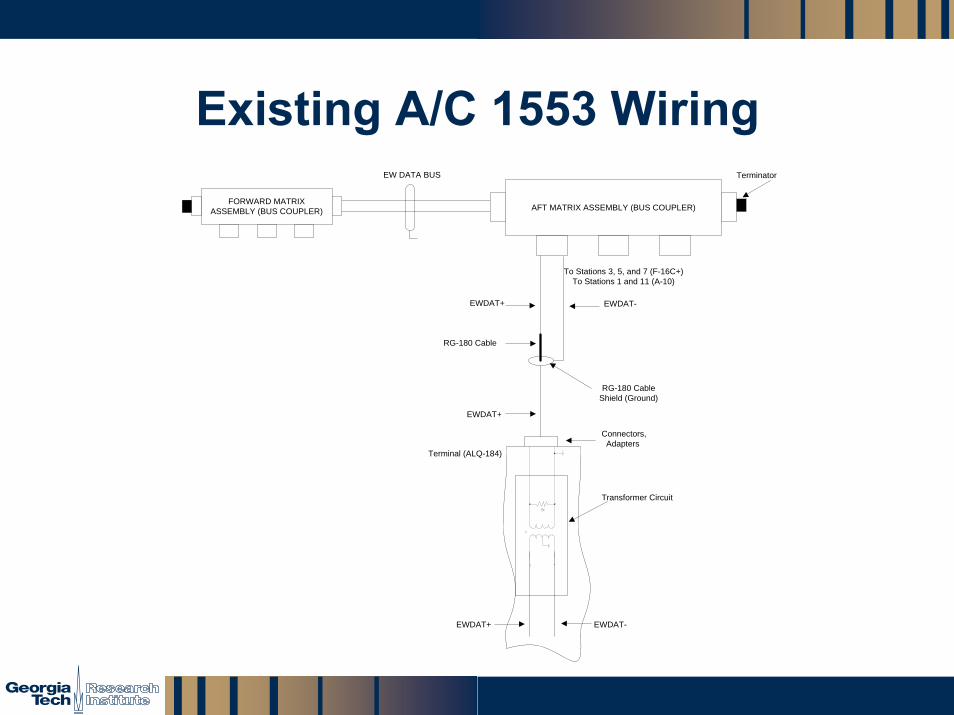
Existing A/C 1553 WiringEW DATA BUS
Transformer Circuit
Terminal (ALQ-184)
RG-180 Cable
To Stations 3, 5, and 7 (F-16C+)To Stations 1 and 11 (A-10)
FORWARD MATRIX ASSEMBLY (BUS COUPLER) AFT MATRIX ASSEMBLY (BUS COUPLER)
EWDAT+ EWDAT-
Connectors, Adapters
RG-180 Cable Shield (Ground)
E+
E-
E+
E-
1:2
93 O1W
EWDAT+
EWDAT+ EWDAT-
Terminator

GTRI_B-14
Computer Simulation
• Computer Simulation provides an approximation of the quality of the signal that can be achieved with a hardware mockup
• A SPICE program was used to model a transmission line defined by the characteristics of the standard and non-standard wiring
• The transmission line was linked to other components, i.e. resistors and transformers, to form the standard 1553 bus design

GTRI_B-15
SPICE Bus Configuration

GTRI_B-16
Impact of Non-Standard Wiring
• BC commands one word transmit from RT (0x0C21 1-T-1-1)
• RT answers with status word followed by 1 data word
• Examine waveform quality (MIL-HDBK-1553, § 40.9)
• Amplitude
• Zero-crossing distortion
• Tailoff
40’ Twinax
39’ Coax

GTRI_B-17
Input Waveform Amplitude at RT
• Measured Voltage
• Twinax: 5.4 v
• Coax: 3.12 v
• Requirement: 0.86 – 14.0 v
40’ Twinax
39’ Coax

GTRI_B-18
Input Waveform Zero-Crossing at RT
• Measurement shown is zero-crossing for first bit of command word to the first bit of the data word
• Measured Time
• Twinax: 2.02 μs
• Coax: 2.04 μs
• Requirement: 2 μs ±150 ns
40’ Twinax
39’ Coax

GTRI_B-19
Input Waveform Tailoff at RT
• Voltage must be less than ±250 mV for the period beginning 2.5 µs following the last mid-bit zero-crossing.
• Both waveforms exhibit clear end to data waveform.

GTRI_B-20
Impact of Non-Standard Wiring – BC• BC commands 1-word
transmit from RT 1 (0x0C21 1-T-1-1)
• RT 1 answers with status word followed by 1 data word
• Examine waveform quality (MIL-HDBK-1553, § 40.9)• Amplitude
• Zero-crossing distortion
• Tailoff

GTRI_B-21
Input Waveform Amplitude at BC
• Measured Voltage
• Twinax: 5.28 v
• Coax: 2.82 v
• Requirement: 0.86 – 14.0 v
40’ Twinax
39’ Coax

GTRI_B-22
Input Waveform Zero-Crossing at BC
• Measurement shown is zero-crossing for first bit of command word to the first bit of the data word
• Measured Time
• Twinax: 2.0 μs
• Coax: 2.06 μs
• Requirement: 2 μs ±150 ns
40’ Twinax
39’ Coax

GTRI_B-23
Input Waveform Tailoff at BC
• Voltage must be less than ±250 mV for the period beginning 2.5 µs following the last mid-bit zero-crossing.
• Both waveforms exhibit clear end to data waveform.

GTRI_B-24
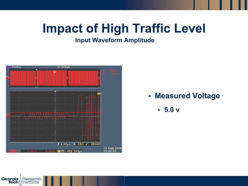
Impact of High Traffic Level
• Maximum bus loading was added to the analysis
• Message changed to a 32-word transfer at the minimum inter-message gap, resulting in a bus loading at just over 99%
GTRI_B-25
Impact of High Traffic Level
• Measured Voltage
• 5.0 v
Input Waveform Amplitude

GTRI_B-26
Impact of High Traffic Level
• Measured Time
• 1.96 µs
Zero-crossing Deviation
GTRI_B-27
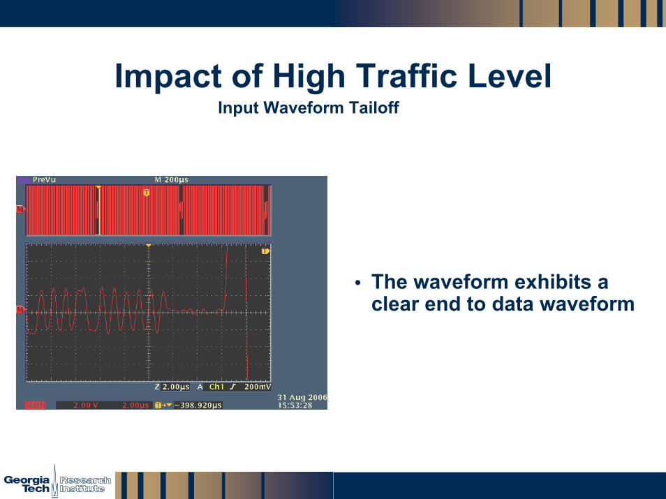
Impact of High Traffic Level
• The waveform exhibits a clear end to data waveform
Input Waveform Tailoff

GTRI_B-28
Use of non-standard wiring OK?
• Short answer: Yes.
• What gets “done-to” should be “un-done” at the terminal end.

GTRI_B-29
Non-Standard A/C 1553 WiringAnalysis
• Sufficient Performance
• Low Maintenance
• Easy Supportability
• Minimal Cost