Agilent Technologies N5393B PCI Express 2.0 (Gen2 ... · Agilent Technologies N5393B PCI Express®...
19
Agilent Technologies N5393B PCI Express ® 2.0 (Gen2) Electrical Performance Validation and Compliance Software for Infiniium Oscilloscopes Data Sheet Table of Contents Features . . . . . . . . . . . . . . . . . . . . . . . . . 3 Benefits . . . . . . . . . . . . . . . . . . . . . . . . . 4 Easy Test Definition . . . . . . . . . . . . . . . 5 Configurability and Guided Connections . . . . . . . . . . . . . . . 6 Reports with Margin Analysis . . . . . . 7 Reference Clock Measurements . . . . . 9 Powerful Debugging Aids . . . . . . . . . 10 Measurement Requirements . . . . . . . 13 Recommended Test Accessories . . . . 14 Oscilloscope Compatibility . . . . . . . . 15 Test Performed . . . . . . . . . . . . . . . . . . 16 Ordering Information . . . . . . . . . . . . . 17 Sales and Service . . . . . . . . . . . . . . . . 19
Transcript of Agilent Technologies N5393B PCI Express 2.0 (Gen2 ... · Agilent Technologies N5393B PCI Express®...
Agilent Technologies
N5393B PCI Express® 2.0 (Gen2) Electrical Performance Validation and Compliance Software for Infiniium Oscilloscopes
Data Sheet
Table of Contents
Features . . . . . . . . . . . . . . . . . . . . . . . . .3
Benefits . . . . . . . . . . . . . . . . . . . . . . . . .4
Easy Test Definition . . . . . . . . . . . . . . . 5
Configurability and
Guided Connections . . . . . . . . . . . . . . .6
Reports with Margin Analysis . . . . . . 7
Reference Clock Measurements . . . . . 9
Powerful Debugging Aids . . . . . . . . . 10
Measurement Requirements . . . . . . . 13
Recommended Test Accessories . . . . 14
Oscilloscope Compatibility . . . . . . . . 15
Test Performed . . . . . . . . . . . . . . . . . . 16
Ordering Information . . . . . . . . . . . . . 17
Sales and Service . . . . . . . . . . . . . . . . 19
2
Verify and debug your PCI Express® designs more easily
Agilent Technologies N5393B PCI Express electrical performance validation and compliance software provides you with a fast and easy way to verify and debug your PCI Express 2.0 and 1.1/1.0a designs for add-in cards and motherboard systems.
The PCI Express electrical test software allows you to automatically execute PCI Express electrical tests, and it displays the results in a flexible report format. In addition to the measurement data, the report provides a margin analysis that shows how closely your device passed or failed each test.
The N5393B PCI Express electrical test software utilizes the prescribed test methods and algorithms as required by the PCI Express Card Electromechanical (CEM) specifications for all current PCI Express Standards. This produces results that are not only consistent with the PCI-SIG’s own SigTest utility, but also provides you with a fast and easy means of executing complex two-port motherboard tests and single port add-in card test with total automation.
The PCI Express electrical performance validation and compliance software performs a wide range of electrical tests as per the PCI Express 2.0, 1.0a and 1.1 electrical specifications for add -in cards and motherboard
1 Peripheral Component Interconnect Special
Interest Group
systems as documented in Section 4 of the base specification and Section 4 of the card electromechanical specification.
Tests for PCI Express 2.0 (based on section 4.7.2., Table 4-8) are also included to help you test your products against for the next generation of this powerful I/O technology
In addition to full swing (800 mV) testing, the N5393B also supports testing for low-power, half-swing devices (400 mV) as per the PCI Express Architecture Mobile Graphics Low-Power Addendum to the PCI Express Base Specification Revision 1.0.

3
The N5393B PCI Express electrical test software offers several features to simplify the validation of PCI Express designs:
• Automated 1M Unit Interval (or greater) testing for highest accuracy
• Results consistent with PCI-SIG SigTest software utility
• Test setup wizard for ease-of-use
• Wide range of electrical tests
• PCI-SIG SigTest clock recovery algorithm
• Automated scope measurement setup
• Test results report generation
• Pass/fail margin analysis
• Reference clock phase jitter analysis (1.1)
• Two-port (explicit clock and data) supported for motherboard signal quality testing
• Support for both full-swing and
low-power, half-swing devices.
With the PCI Express electrical test software, you can use the same oscilloscope you use for everyday debugging to perform automated testing and margin analysis based on the PCI-SIG-specified tests.
PCI Express compliance testing
To pass signal quality testing at a PCI-SIG-sponsored compliance workshop, your product must successfully pass “Gold Suite” testing, based on the PCI-SIG SigTest application. The SigTest application tests your device against the minimum signal-quality performance requirements for PCI. If you are developing receivers and transmitters for add-in boards and system motherboards, the N5393B PCI Express electrical test software helps you execute all the SigTest tests and additional oscilloscope already completed tests. See the list of tests in Table 3 on page 15 (for 1.1 test coverage).
While SigTest tests provide a good overview of PCI Express electrical signal quality, they address only a small subset of the electrical compliance measurements specified in the PCI-SIG specification. The SigTest application also provides minimal reporting capability with pass/fail indication and measurement values, and has limited debugging capabilities to decipher eye mask violations or excessive jitter.
For PCI Express 2.0 measurements, the N5393B software automatically calculates deterministic jitter and total jitter at 10-12 BER. Random jitter is also reported for completeness and a voltage margin “eye” diagram is included in the final HTML report. DJ and TJ values are specified in the PCIe 2.0 specification and are required for compliance verification.
Features
PCI Express 2.0 supports data rates up to 5.0 GT/s as shown
above (-3.5 dB de-empasis)

4
N5393B benefits
The N5393B PCI Express electrical test software saves you time by setting the stage for automatic execution of PCI Express electrical tests. Part of the difficulty of performing electrical tests for PCI Express is hooking up the oscilloscope, loading the proper setup files, and then analyzing the measured results by comparing them to limits published in the specification. The PCI Express electrical test software does much of this work for you. In addition, if you discover a problem with
your device, robust debug tools are available to aid in root-cause analysis. These debug tools are provided by the Agilent E2688A high-speed serial data analysis software, which you must install on your oscilloscope to use the PCI Express electrical test software.
The N5393B PCI Express electrical test software offers many more electrical tests than the SigTest application. Unlike the SigTest application, the N5393B PCI Express electrical test software automatically
configures the oscilloscope for each test, and it provides an informative results report that includes margin analysis indicating how close your product is to passing or failing a particular test assertion. Table 1 shows a side-by-side comparison of the capabilities of the SigTest application and the Agilent N5393B PCI Express electrical test software. A list of the measurements made by the PCI Express electrical test software can be found in Table 3, (Table 3 contains comparison of SigTest vs. Agilent).
Capability Agilent N5393B PCI-SIG SigTest
Number of measurement assertions 16+ 4
Support for PCIe 1.0a, 1.1, 2.0 Yes Yes
Reference clock tests 10 (1.1) 0*
Automated oscilloscope setup for Yes, guided No, single setup
each measurement
Measurement results Pass/fail with margin analysis Pass/fail with measured value
CEM based measurments methodology Yes Yes
Clock recovery method PCI-SIG SigTest or 1st/2nd order PLL PCI-SIG SigTest
Brick wall filter (2.0 testing) Yes Yes
Custom HTML report generation Yes No
Support for low power device Yes No
Selectable number of tests performed Yes No
Multi-trial run support Yes No
Debug mode for “what if” analysis Yes No
Compliance test boards supported CBB1, CBB2, CLB1, CLB2 CBB1, CBB2, CLB1, CLB2
* PCI-Sig offers a separate utility (Clock_Jitter) for analyzing reference clock phase jitter.
Table 1. Comparison of capabilities of the Agilent PCI Express electrical test software and the PCI-SIG SigTest application.
Benefits
5
Easy Test Definition
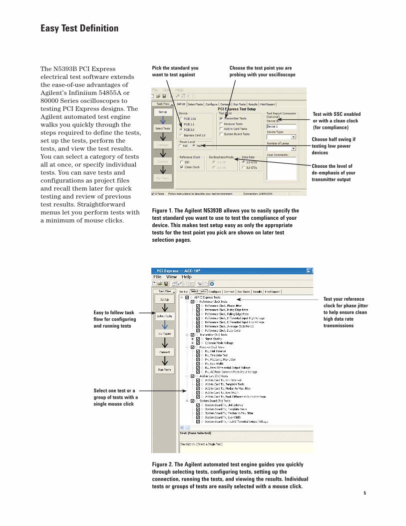
The N5393B PCI Express electrical test software extends the ease-of-use advantages of Agilent’s Infiniium 54855A or 80000 Series oscilloscopes to testing PCI Express designs. The Agilent automated test engine walks you quickly through the steps required to define the tests, set up the tests, perform the tests, and view the test results. You can select a category of tests all at once, or specify individual tests. You can save tests and configurations as project files and recall them later for quick testing and review of previous test results. Straightforward menus let you perform tests with a minimum of mouse clicks.
Figure 2. The Agilent automated test engine guides you quickly
through selecting tests, configuring tests, setting up the
connection, running the tests, and viewing the results. Individual
tests or groups of tests are easily selected with a mouse click.
Easy to follow task
flow for configuring
and running tests
Select one test or a
group of tests with a
single mouse click
Test with SSC enabled
or with a clean clock
(for compliance)
Pick the standard you
want to test against
Choose the test point you are
probing with your oscilloscope
Figure 1. The Agilent N5393B allows you to easily specify the
test standard you want to use to test the compliance of your
device. This makes test setup easy as only the appropriate
tests for the test point you pick are shown on later test
selection pages.
Test your reference
clock for phase jitter
to help ensure clean
high data rate
transmissions
Choose the level of
de-emphasis of your
transmitter output
Choose half swing if
testing low power
devices
6
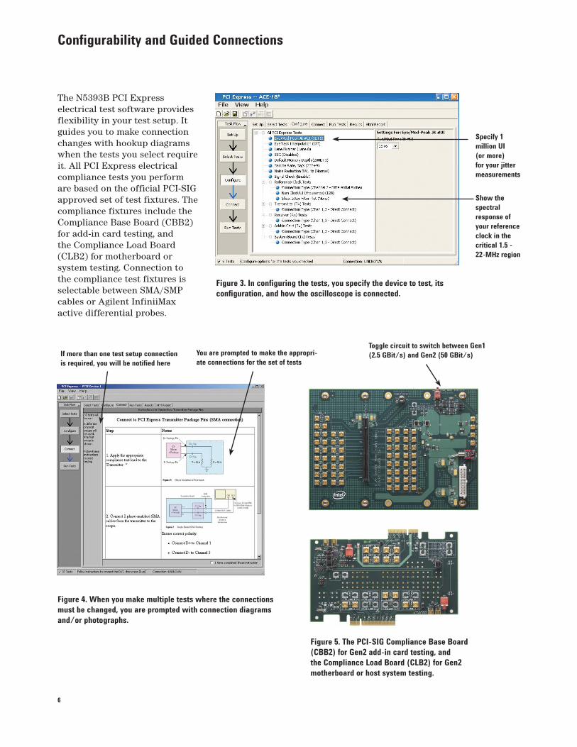
Configurability and Guided Connections
The N5393B PCI Express electrical test software provides flexibility in your test setup. It guides you to make connection changes with hookup diagrams when the tests you select require it. All PCI Express electrical compliance tests you perform are based on the official PCI-SIG approved set of test fixtures. The compliance fixtures include the Compliance Base Board (CBB2) for add-in card testing, and the Compliance Load Board (CLB2) for motherboard or system testing. Connection to the compliance test fixtures is selectable between SMA/SMP cables or Agilent InfiniiMax active differential probes.
Figure 4. When you make multiple tests where the connections
must be changed, you are prompted with connection diagrams
and/or photographs.
If more than one test setup connection
is required, you will be notified here
You are prompted to make the appropri-
ate connections for the set of tests
Figure 5. The PCI-SIG Compliance Base Board
(CBB2) for Gen2 add-in card testing, and
the Compliance Load Board (CLB2) for Gen2
motherboard or host system testing.
Figure 3. In configuring the tests, you specify the device to test, its
configuration, and how the oscilloscope is connected.
Specify 1
million UI
(or more)
for your jitter
measurements
Show the
spectral
response of
your reference
clock in the
critical 1.5 -
22-MHz region
Toggle circuit to switch between Gen1
(2.5 GBit/s) and Gen2 (50 GBit/s)
7
Reports with Margin Analysis
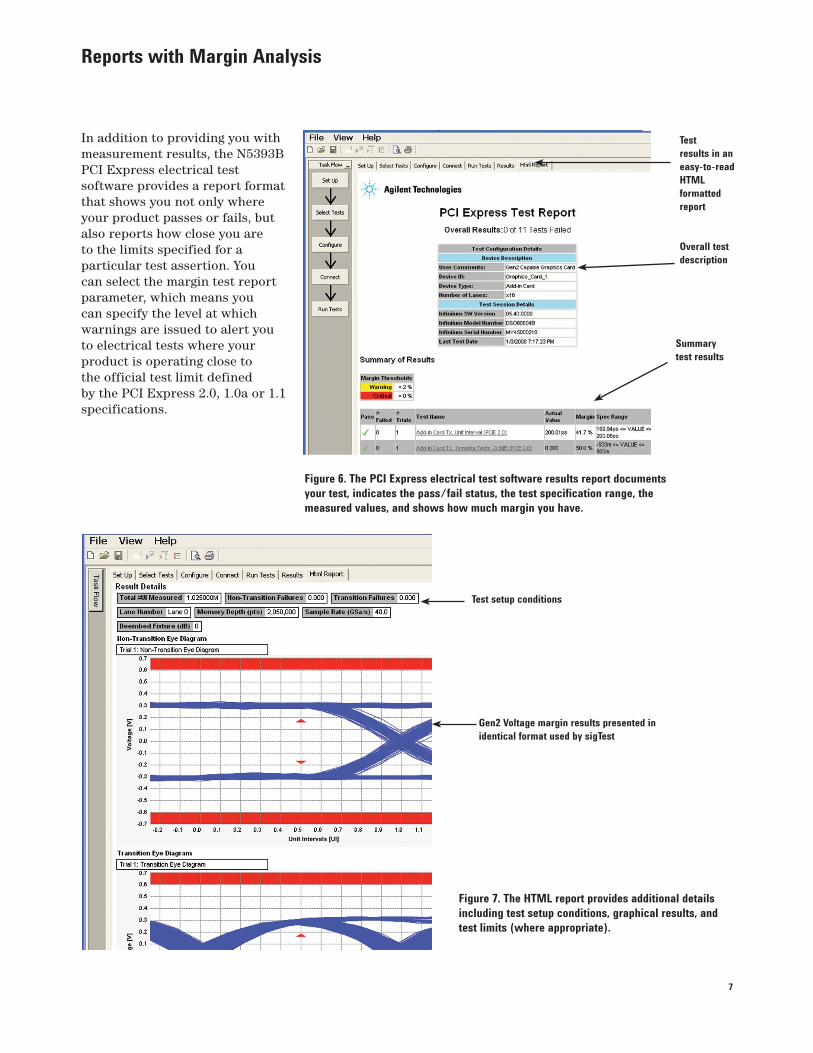
In addition to providing you with measurement results, the N5393B PCI Express electrical test software provides a report format that shows you not only where your product passes or fails, but also reports how close you are to the limits specified for a particular test assertion. You can select the margin test report parameter, which means you can specify the level at which warnings are issued to alert you to electrical tests where your product is operating close to the official test limit defined by the PCI Express 2.0, 1.0a or 1.1 specifications.
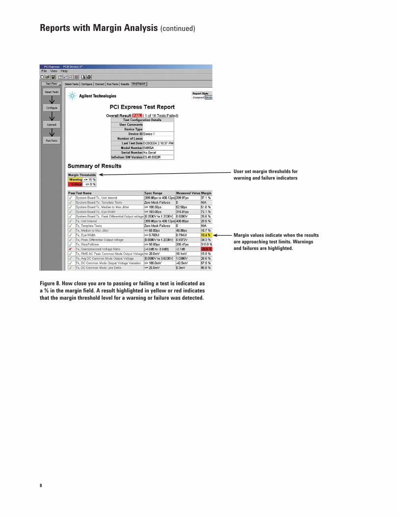
Figure 7. The HTML report provides additional details
including test setup conditions, graphical results, and
test limits (where appropriate).
Figure 6. The PCI Express electrical test software results report documents
your test, indicates the pass/fail status, the test specification range, the
measured values, and shows how much margin you have.
Test
results in an
easy-to-read
HTML
formatted
report
Overall test
description
Summary
test results
Gen2 Voltage margin results presented in
identical format used by sigTest
Test setup conditions
8
Figure 8. How close you are to passing or failing a test is indicated as
a % in the margin field. A result highlighted in yellow or red indicates
that the margin threshold level for a warning or failure was detected.
Reports with Margin Analysis (continued)
User set margin thresholds for
warning and failure indicators
Margin values indicate when the results
are approaching test limits. Warnings
and failures are highlighted.
9
Reference Clock Measurements
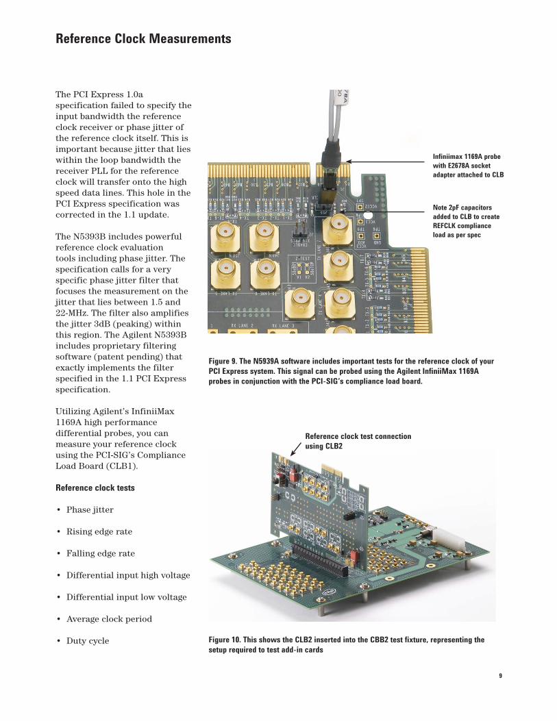
The PCI Express 1.0a specification failed to specify the input bandwidth the reference clock receiver or phase jitter of the reference clock itself. This is important because jitter that lies within the loop bandwidth the receiver PLL for the reference clock will transfer onto the high speed data lines. This hole in the PCI Express specification was corrected in the 1.1 update.
The N5393B includes powerful reference clock evaluation tools including phase jitter. The specification calls for a very specific phase jitter filter that focuses the measurement on the jitter that lies between 1.5 and 22-MHz. The filter also amplifies the jitter 3dB (peaking) within this region. The Agilent N5393B includes proprietary filtering software (patent pending) that exactly implements the filter specified in the 1.1 PCI Express specification.
Utilizing Agilent’s InfiniiMax 1169A high performance differential probes, you can measure your reference clock using the PCI-SIG’s Compliance Load Board (CLB1).
Reference clock tests
• Phase jitter
• Rising edge rate
• Falling edge rate
• Differential input high voltage
• Differential input low voltage
• Average clock period
• Duty cycle
Infiniimax 1169A probe
with E2678A socket
adapter attached to CLB
Note 2pF capacitors
added to CLB to create
REFCLK compliance
load as per spec
Figure 9. The N5939A software includes important tests for the reference clock of your
PCI Express system. This signal can be probed using the Agilent InfiniiMax 1169A
probes in conjunction with the PCI-SIG’s compliance load board.
Figure 10. This shows the CLB2 inserted into the CBB2 test fixture, representing the
setup required to test add-in cards
Reference clock test connection
using CLB2
10
Powerful Debugging Aids
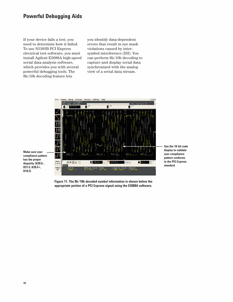
If your device fails a test, you need to determine how it failed. To use N5393B PCI Express electrical test software, you must install Agilent E2688A high-speed serial data analysis software, which provides you with several powerful debugging tools. The 8b/10b decoding feature lets
Figure 11. The 8b/10b decoded symbol information is shown below the
appropriate portion of a PCI Express signal using the E2688A software.
Make sure your
compliance pattern
has the proper
disparity (K28.5-,
D21.5, K28.5+,
D10.2)
Use the 10-bit code
display to validate
your compliance
pattern conforms
to the PCI Express
standard
you identify data-dependent errors that result in eye mask violations caused by inter-symbol interference (ISI). You can perform 8b/10b decoding to capture and display serial data synchronized with the analog view of a serial data stream.
11
Powerful Debugging Aids (continued)
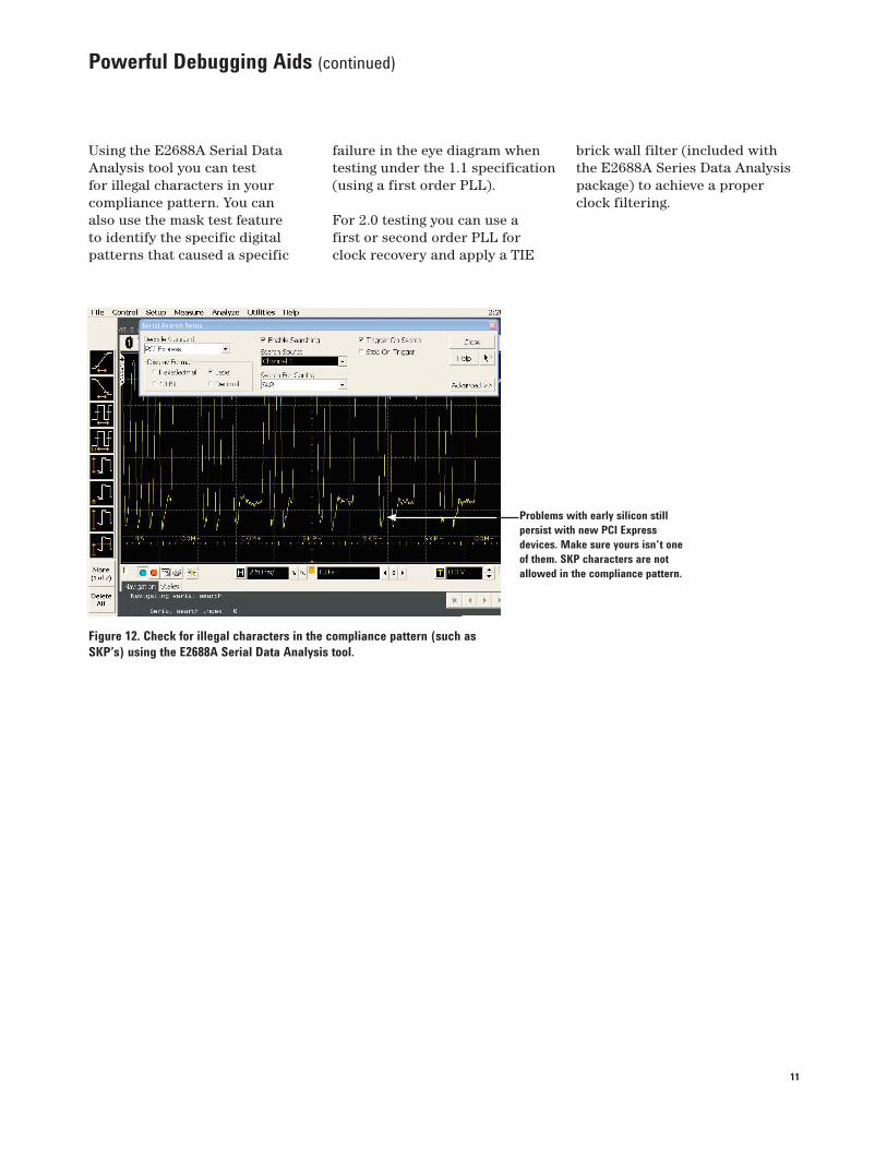
Using the E2688A Serial Data Analysis tool you can test for illegal characters in your compliance pattern. You can also use the mask test feature to identify the specific digital patterns that caused a specific
Figure 12. Check for illegal characters in the compliance pattern (such as
SKP’s) using the E2688A Serial Data Analysis tool.
Problems with early silicon still
persist with new PCI Express
devices. Make sure yours isn’t one
of them. SKP characters are not
allowed in the compliance pattern.
failure in the eye diagram when testing under the 1.1 specification (using a first order PLL).
For 2.0 testing you can use a first or second order PLL for clock recovery and apply a TIE
brick wall filter (included with the E2688A Series Data Analysis package) to achieve a proper clock filtering.
12
Powerful Debugging Aids (continued)
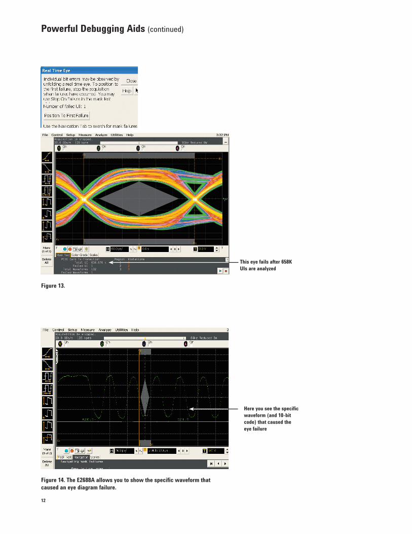
Figure 14. The E2688A allows you to show the specific waveform that
caused an eye diagram failure.
Here you see the specific
waveform (and 10-bit
code) that caused the
eye failure
Figure 13.
This eye fails after 658K
UIs are analyzed
13
Measurement Requirements
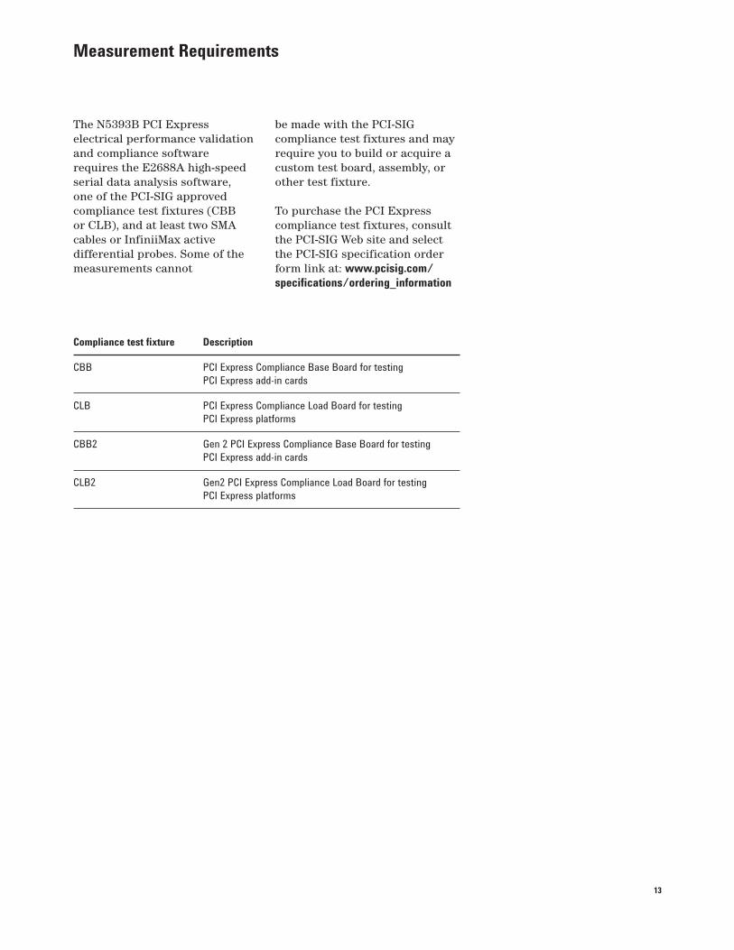
The N5393B PCI Express electrical performance validation and compliance software requires the E2688A high-speed serial data analysis software, one of the PCI-SIG approved compliance test fixtures (CBB or CLB), and at least two SMA cables or InfiniiMax active differential probes. Some of the measurements cannot
Compliance test fixture Description
CBB PCI Express Compliance Base Board for testing
PCI Express add-in cards
CLB PCI Express Compliance Load Board for testing
PCI Express platforms
CBB2 Gen 2 PCI Express Compliance Base Board for testing
PCI Express add-in cards
CLB2 Gen2 PCI Express Compliance Load Board for testing
PCI Express platforms
be made with the PCI-SIG compliance test fixtures and may require you to build or acquire a custom test board, assembly, or other test fixture.
To purchase the PCI Express compliance test fixtures, consult the PCI-SIG Web site and select the PCI-SIG specification order form link at: www.pcisig.com/
specifications/ordering_information
14
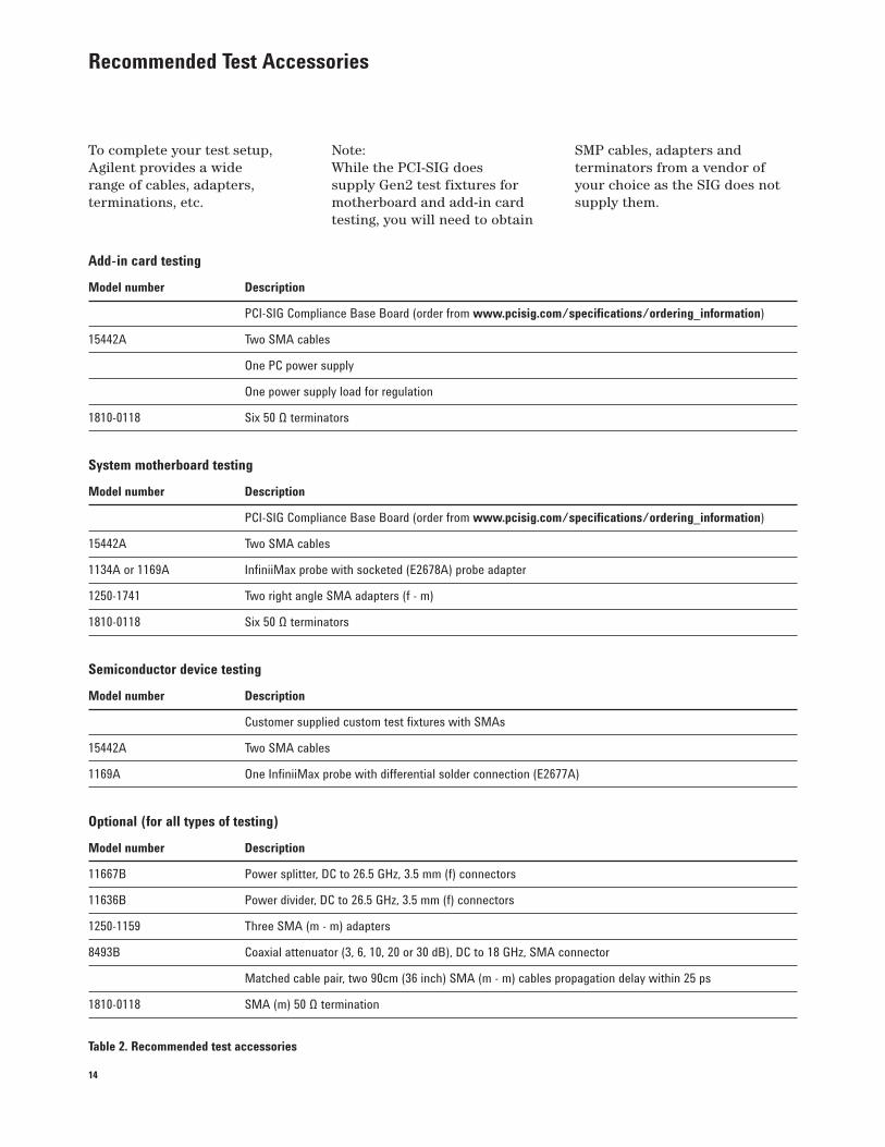
Recommended Test Accessories
To complete your test setup, Agilent provides a wide range of cables, adapters, terminations, etc.
Add-in card testing
Model number Description
PCI-SIG Compliance Base Board (order from www.pcisig.com/specifications/ordering_information)
15442A Two SMA cables
One PC power supply
One power supply load for regulation
1810-0118 Six 50 Ω terminators
System motherboard testing
Model number Description
PCI-SIG Compliance Base Board (order from www.pcisig.com/specifications/ordering_information)
15442A Two SMA cables
1134A or 1169A InfiniiMax probe with socketed (E2678A) probe adapter
1250-1741 Two right angle SMA adapters (f - m)
1810-0118 Six 50 Ω terminators
Semiconductor device testing
Model number Description
Customer supplied custom test fixtures with SMAs
15442A Two SMA cables
1169A One InfiniiMax probe with differential solder connection (E2677A)
Optional (for all types of testing)
Model number Description
11667B Power splitter, DC to 26.5 GHz, 3.5 mm (f) connectors
11636B Power divider, DC to 26.5 GHz, 3.5 mm (f) connectors
1250-1159 Three SMA (m - m) adapters
8493B Coaxial attenuator (3, 6, 10, 20 or 30 dB), DC to 18 GHz, SMA connector
Matched cable pair, two 90cm (36 inch) SMA (m - m) cables propagation delay within 25 ps
1810-0118 SMA (m) 50 Ω termination
Table 2. Recommended test accessories
Note:While the PCI-SIG does supply Gen2 test fixtures for motherboard and add-in card testing, you will need to obtain
SMP cables, adapters and terminators from a vendor of your choice as the SIG does not supply them.
15
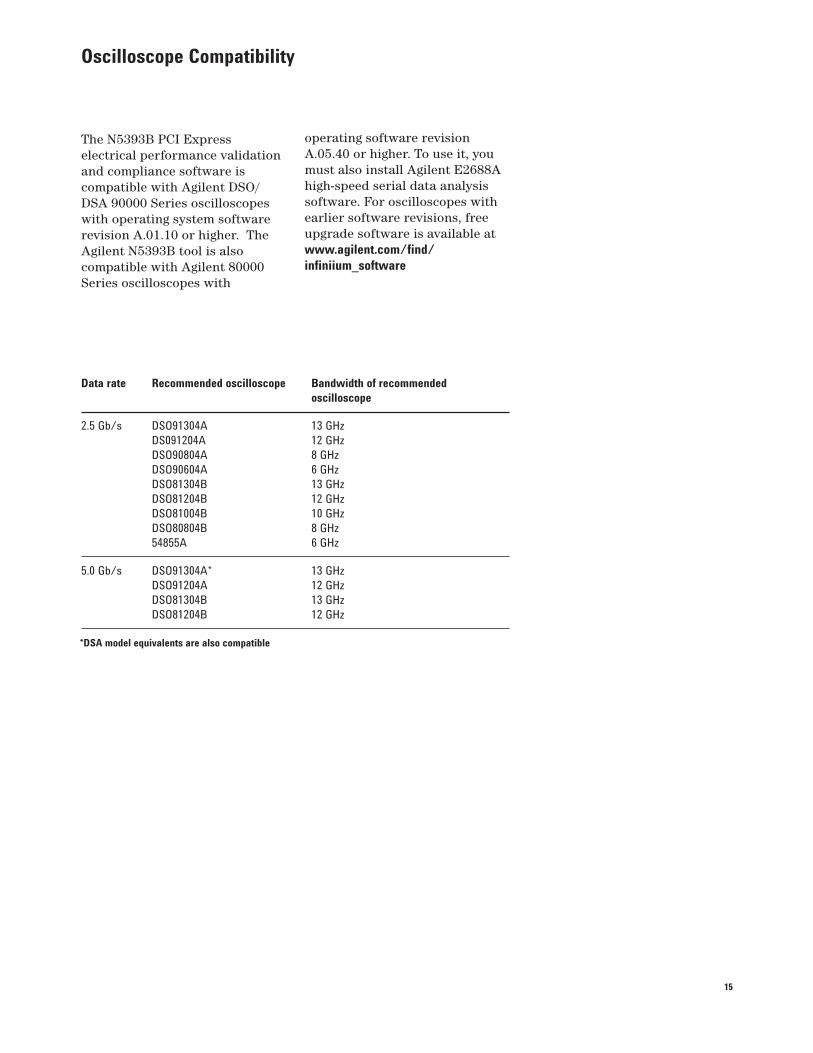
Oscilloscope Compatibility
The N5393B PCI Express electrical performance validation and compliance software is compatible with Agilent DSO/DSA 90000 Series oscilloscopes with operating system software revision A.01.10 or higher. The Agilent N5393B tool is also compatible with Agilent 80000Series oscilloscopes with
Data rate Recommended oscilloscope Bandwidth of recommended
oscilloscope
2.5 Gb/s DSO91304A 13 GHz
DS091204A 12 GHz
DSO90804A 8 GHz
DSO90604A 6 GHz
DSO81304B 13 GHz
DSO81204B 12 GHz
DSO81004B 10 GHz
DSO80804B 8 GHz
54855A 6 GHz
5.0 Gb/s DSO91304A* 13 GHz
DSO91204A 12 GHz
DSO81304B 13 GHz
DSO81204B 12 GHz
operating software revisionA.05.40 or higher. To use it, you must also install Agilent E2688A high-speed serial data analysis software. For oscilloscopes with earlier software revisions, free upgrade software is available at www.agilent.com/find/
infiniium_software
*DSA model equivalents are also compatible
16
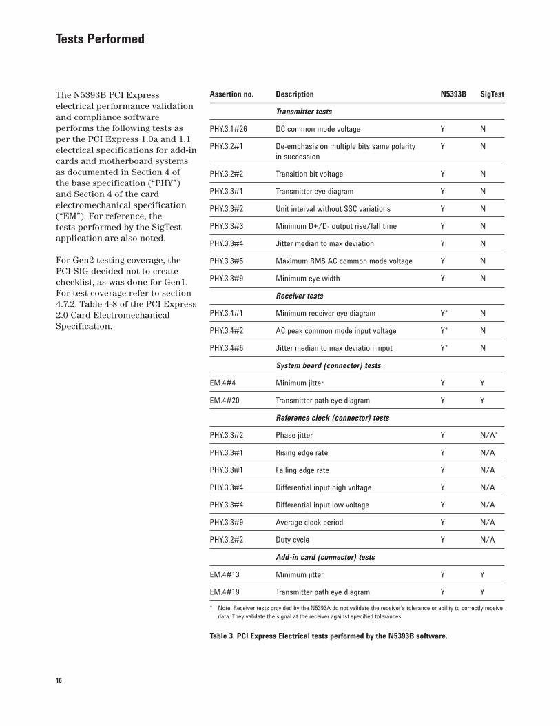
Tests Performed
The N5393B PCI Express electrical performance validation and compliance software performs the following tests as per the PCI Express 1.0a and 1.1 electrical specifications for add-in cards and motherboard systems as documented in Section 4 of the base specification (“PHY”) and Section 4 of the card electromechanical specification (“EM”). For reference, the tests performed by the SigTest application are also noted.
For Gen2 testing coverage, the PCI-SIG decided not to create checklist, as was done for Gen1. For test coverage refer to section 4.7.2. Table 4-8 of the PCI Express 2.0 Card Electromechanical Specification.
Assertion no. Description N5393B SigTest
Transmitter tests
PHY.3.1#26 DC common mode voltage Y N
PHY.3.2#1 De-emphasis on multiple bits same polarity Y N
in succession
PHY.3.2#2 Transition bit voltage Y N
PHY.3.3#1 Transmitter eye diagram Y N
PHY.3.3#2 Unit interval without SSC variations Y N
PHY.3.3#3 Minimum D+/D- output rise/fall time Y N
PHY.3.3#4 Jitter median to max deviation Y N
PHY.3.3#5 Maximum RMS AC common mode voltage Y N
PHY.3.3#9 Minimum eye width Y N
Receiver tests
PHY.3.4#1 Minimum receiver eye diagram Y* N
PHY.3.4#2 AC peak common mode input voltage Y* N
PHY.3.4#6 Jitter median to max deviation input Y* N
System board (connector) tests
EM.4#4 Minimum jitter Y Y
EM.4#20 Transmitter path eye diagram Y Y
Reference clock (connector) tests
PHY.3.3#2 Phase jitter Y N/A*
PHY.3.3#1 Rising edge rate Y N/A
PHY.3.3#1 Falling edge rate Y N/A
PHY.3.3#4 Differential input high voltage Y N/A
PHY.3.3#4 Differential input low voltage Y N/A
PHY.3.3#9 Average clock period Y N/A
PHY.3.2#2 Duty cycle Y N/A
Add-in card (connector) tests
EM.4#13 Minimum jitter Y Y
EM.4#19 Transmitter path eye diagram Y Y
* Note: Receiver tests provided by the N5393A do not validate the receiver’s tolerance or ability to correctly receive
data. They validate the signal at the receiver against specified tolerances.
Table 3. PCI Express Electrical tests performed by the N5393B software.
17
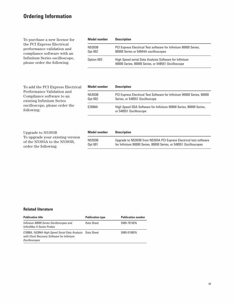
Ordering Information
To purchase a new license for the PCI Express Electrical performance validation and compliance software with an Infiniium Series oscilloscope, please order the following:
Related literature
Publication title Publication type Publication number
Infiniium 90000 Series Oscilloscopes and Data Sheet 5989-7819EN
InfiniiMax II Series Probes
E2688A, N5384A High-Speed Serial Data Analysis Data Sheet 5989-0108EN
with Clock Recovery Software for Infiniium
Oscilloscopes
Model number Description
N5393B PCI Express Electrical Test software for Infiniium 90000 Series,
Opt 002 80000 Series or 54844A oscilloscopes
Option 003 High Speed serial Data Analysis Software for Infiniium
90000 Series, 80000 Series, or 548551 Oscilloscope
Model number Description
N5393B PCI Express Electrical Test Software for Infiniium 90000 Series, 80000
Opt 002 Series, or 548551 Oscilloscope
E2688A High Speed SDA Software for Infiniium 90000 Series, 80000 Series,
or 548551 Oscilloscope
To add the PCI Express Electrical Performance Validation and Compliance software to an existing Infiniium Series oscilloscope, please order the following:
Model number Description
N5393B Upgrade to N5393B from N5393A PCI Express Electrical test software
Opt 001 for Infiniium 90000 Series, 80000 Series, or 548551 Oscilloscopes
Upgrade to N5393BTo upgrade your existing version of the N5393A to the N5393B, order the following:
18
Agilent Technologies Oscilloscopes
Multiple form factors from 20 MHz to >90 GHz | Industry leading specs | Powerful applications
PCI Express® and PCI-SIG® are registered
trademarks of PCI-SIG.
Remove all doubt
Our repair and calibration services
will get your equipment back to you,
performing like new, when promised.
You will get full value out of your Agilent
equipment throughout its lifetime. Your
equipment will be serviced by Agilent-
trained technicians using the latest
factory calibration procedures, automated
repair diagnostics and genuine parts. You
will always have the utmost confidence
in your measurements.
Agilent offers a wide range of additional
expert test and measurement services
for your equipment, including initial
start-up assistance, onsite education
and training, as well as design, system
integration, and project management.
For more information on repair and
calibration services, go to:
www.agilent.com/find/removealldoubt
www.agilent.com/find/open
Agilent Open simplifies the process of
connecting and programming test systems
to help engineers design, validate and
manufacture electronic products. Agilent
offers open connectivity for a broad range
of system-ready instruments, open industry
software, PC-standard I/O and global
support, which are combined to more
easily integrate test system development.
www.agilent.com/find/emailupdates
Get the latest information on the products
and applications you select.
www.agilent.com/find/agilentdirect
Quickly choose and use your test
equipment solutions with confidence.
Agilent Email Updates
Agilent Direct
www.lxistandard.org
LXI is the LAN-based successor to GPIB,
providing faster, more efficient connectivity.
Agilent is a founding member of the LXI
consortium.
www.agilent.comwww.agilent.com/fi nd/N5393B
For more information on Agilent Technologies’
products, applications or services, please
contact your local Agilent office. The
complete list is available at:
www.agilent.com/fi nd/contactus
Americas
Canada (877) 894-4414
Latin America 305 269 7500
United States (800) 829-4444
Asia Pacifi c
Australia 1 800 629 485
China 800 810 0189
Hong Kong 800 938 693
India 1 800 112 929
Japan 0120 (421) 345
Korea 080 769 0800
Malaysia 1 800 888 848
Singapore 1 800 375 8100
Taiwan 0800 047 866
Thailand 1 800 226 008
Europe & Middle East
Austria 01 36027 71571
Belgium 32 (0) 2 404 93 40
Denmark 45 70 13 15 15
Finland 358 (0) 10 855 2100
France 0825 010 700
Germany 07031 464 6333
Ireland 1890 924 204
Israel 972-3-9288-504/544
Italy 39 02 92 60 8484
Netherlands 31 (0) 20 547 2111
Spain 34 (91) 631 3300
Sweden 0200-88 22 55
Switzerland 0800 80 53 53
United Kingdom 44 (0) 118 9276201
Other European Countries:
www.agilent.com/fi nd/contactus
Revised: October 1, 2008
Product specifi cations and descriptions
in this document subject to change
without notice.
© Agilent Technologies, Inc. 2009
Printed in USA, April 30, 2009
5989-1240EN