Agilent Technologies N2600A WireScope 350 User’s … Scope 350/manual_350.pdf · Agilent...
150
Agilent Technologies Agilent Technologies N2600A WireScope 350 User’s Manual Version 3.0
Transcript of Agilent Technologies N2600A WireScope 350 User’s … Scope 350/manual_350.pdf · Agilent...

Agilent Technologies
Agilent Technologies N2600A
WireScope 350
User’s ManualVersion 3.0

ii
1RWLFHV
Notices
No part of this manual may be reproduced in any form or by any means (including electronic storage and retrieval or transla-tion into a foreign language) without prior agreement and written consent from Agi-lent Technologies, Inc. as governed by United States and international copyright laws.
Manual Part Number
N2605A-070
Edition
Version 3.0 July 2002
Printed in USA
Agilent Technologies, Inc.90 Central StreetBoxborough, MA 01719 USA
Warranty
The material contained in this docu-ment is provided “as is,” and is sub-ject to being changed without notice in future editions. Further, to the max-imum extent permitted by applicable law, Agilent Technologies disclaims all warranties of merchantability and fitness for a particular purpose. Agi-lent Technologies shall not be liable for errors or for incidental or conse-quential damages in connection with the furnishing, use, or performance of this document or of any of the prod-ucts to which it pertains. Should Agi-lent Technologies have a written contract with the user and should any of the contract terms conflict with these terms the contract terms shall control.
Technology Licenses
The hardware and/or software described in this document are furnished under a license and may be used or copied only in accordance with the terms of such license.
Restricted Rights Legend
If software is for use in the performance of a U.S. Government prime contract or sub-contract, Software is delivered and licensed as “Commercial computer soft-ware” as defined in DFAR 252.227-7014 (June 1995), or as a “commercial item” as defined in FAR 2.101(a) or as “Restricted computer software” as defined in FAR
52.227-19 (June 1987) or any equivalent agency regulation or contract clause. Use, duplication or disclosure of Software is subject to Agilent Technologies’ standard commercial license terms, and non-DOD Departments and Agencies of the U.S. Gov-ernment will receive no greater than Restricted Rights as defined in FAR 52.227-19(c)(1-2) (June 1987). U.S. Govern-ment users will receive no greater than Limited Rights as defined in FAR 52.227-14 (June 1987) or DFAR 252.227-7015 (b)(2) (November 1995), as applicable in any technical data.
Safety Notices
A CAUTION notice denotes a haz-ard. It calls attention to an operat-ing procedure, practice, or the like that, if not correctly performed or adhered to, could result in damage to the product or loss of important data. Do not proceed beyond a CAUTION notice until the indicated conditions are fully understood and met.
A WARNING notice denotes a haz-ard. It calls attention to an operat-ing procedure, practice, or the like that, if not correctly performed or adhered to, could result in personal injury or death. Do not proceed beyond a WARNING notice until the indicated conditions are fully understood and met.

$ERXW7KLV%RRN
iii
About This Book
This manual covers the use of WireScope 350 testers using software version 3.0.
Note that some systems running earlier software may not provide all of the features described in this manual; systems running later versions of software may operate differently than described in this manual. Be sure to refer to any user’s manual supplements or release notes that came with the unit, or call 800-452-4844.
Getting Started
Chapter 1, Getting Started, introduces the WireScope 350 tester, (called the Tester in this manual) and illustrates its features and controls.
Chapter 2, Using WireScope, describes how to perform basic functions with the Tester, such as connecting power, installing probes and CompactFlash™ cards, downloading software, and working with the WireScope 350 software.
Cabling Certification
Chapter 3, Certifying Copper Cabling, describes how to set up and run Autotests on copper cabling.
Chapter 4, Certifying Fiber Cabling, describes how to set up and run Autotests on optical fiber cabling.
Chapter 5, Saving Test Results, describes how to save test results.
Chapter 6, Expert Mode for Copper Testing, explains advanced configuration options for testing copper cabling.
Chapter 7, Expert Mode for Fiber Testing, explains advanced configuration options for testing optical fiber cabling.
Reference
Chapter 8, Reference, describes the measurement details, calibration, and memory usage.
Chapter 9, Specifications, describes the WireScope 350’s and Fiber SmartProbe’s specifications.

iv
$ERXW7KLV%RRN

WireScope 350 User’s Guide v
ContentsNotices iiAbout This Book iii
Getting Started iiiCabling Certification iiiReference iii
1 Getting Started
WireScope at a Glance 1-2Control Buttons 1-2Ports 1-3
System Requirements 1-4WireScope 350 Hardware 1-5
Touch Screen User Interface 1-5CompactFlash™ Card Slot 1-5Items Supplied 1-5Optional Accessories 1-6
WireScope SmartProbes 1-7WireScope probe configuration warnings 1-7Link and Channel SmartProbes 1-8Fiber SmartProbe+ 1-9
Cabling Certification and Tests 1-10Cabling Certification Standards 1-10
Copper Cable Testing 1-10Link and Channel Tests 1-10
Optical Fiber Cable Testing 1-12WireScope User Interface 1-13
Touch Screen Layout 1-13Onscreen Buttons 1-14Data Entry Options 1-14Online Help 1-15
The DualRemote 350 1-17Control Buttons 1-17Indicators 1-18
WireScope Software 1-20Probe Detection 1-20Digital Fault Finding 1-20Software Upgrades 1-20
Standard Warranty 1-20

vi WireScope 350 User’s Guide
Technical Support 1-21Before you call 1-21
2 Using WireScope
External and Battery Power 2-2Using External Power 2-2Removing the Battery 2-2Battery Safety 2-3
Connecting to Cabling for Certification 2-4SmartProbes 2-4
Using Talksets 2-5Talkset Controls 2-5
Using CompactFlash™ Cards 2-6Installing CompactFlash™ Cards 2-6Configuring CompactFlash™ Cards 2-6
Upgrading the WireScope Software 2-7Viewing Software and Hardware Version Information 2-8The System Settings Menu 2-9The Database Menu 2-11Printing Labels 2-12
Printing Labels On Site 2-12Printing Labels from a PC 2-13
3 Certifying Copper Cabling
Copper Testing Overview 3-2Calibrating the Tester 3-2Setting Up an Autotest 3-4
Opening the Setup Menu 3-4Choosing the Profile 3-4Choosing the Standard 3-4Entering the Site Name 3-5Choosing the Labeling Format 3-6Choosing the Cable Type 3-14Choosing the Connector Type 3-16Choosing the Cable Pairing Convention 3-17Entering the Operator Names 3-18
Running an Autotest 3-20
4 Certifying Fiber Cabling
Fiber Testing Overview 4-2Calibrating the Tester 4-4
Calibrating for Double-Ended Testing 4-4Calibrating for Single-Ended Testing 4-7

WireScope 350 User’s Guide vii
Setting Up an Autotest 4-9Opening the Settings Menu 4-9Choosing the Test Configuration 4-10Setting the Loss Limit 4-10Setting the Length Limit 4-13Choosing the Network Limit 4-14Entering the Site Name 4-15Choosing the Labeling Format 4-16Choosing the Cable Type 4-16Setting the Modal Bandwidth 4-18Choosing the Connector Type 4-18Entering the Operator Names 4-20
Running an Autotest 4-22
5 Saving Test Results
Test Results Display 5-2Saving Test Results 5-3
Choosing the Data Storage Location 5-3Saving the Results 5-4
Viewing Result Details 5-5Interpreting Test Results Detail Screens 5-7
6 Expert Mode for Copper Testing
About Expert Mode 6-3Changing to Expert Mode 6-3The Expert Autotest Setup 6-4
Choosing an Existing Settings Profile 6-4Editing an Existing Settings Profile to Remove a Lock 6-5Creating a New Settings Profile 6-6Setting the Test Limit 6-8Viewing Probe Information 6-9Setting Network Limits 6-10Entering the Site Name 6-11Choosing the Labeling Format 6-12Choosing the Cable Type 6-12Choosing the Connector Type 6-13Choosing the Cable Pairing Convention 6-13Setting the Measurements 6-14Setting the Maximum Frequency 6-16Setting the Plot Storage Requirements 6-16Setting the Storage Location 6-17Setting the Operator Names 6-17

viii WireScope 350 User’s Guide
The Expert Tools Menu 6-18Running a Quick Check 6-19Certifying a Network 6-20Blinking the Port 6-21Learning the NVP of a Cable 6-22Measuring the Cable Length 6-23
Running COAX and TWINAX Autotests 6-25COAX Testing 6-25Twinax Testing 6-26
7 Expert Mode for Fiber Testing
About Fiber Expert Mode 7-2Changing to Expert Mode 7-2Viewing Probe Information 7-3The Fiber Tools Menu 7-5
Using the Loss Meter 7-5Measuring Length and Delay 7-6Using the Power Meter 7-6Using Trace Mode 7-7Learning the NVP of a Fiber 7-7
8 Reference
Measurements 8-2Wiremap 8-2Length 8-2Propagation Delay and Skew 8-2Near-end Crosstalk (NEXT) 8-3Attenuation 8-3Return Loss 8-4Equal Level Far-End Crosstalk (ELFEXT) 8-4Attenuation-to-Crosstalk Ratio (ACR) 8-4Power Sum NEXT (PSNEXT) 8-4Power Sum ELFEXT (PSELEXT) 8-5Power Sum ACR (PSACR) 8-5Resistance 8-5Ambient Noise 8-5
Calibration 8-6Measurement Calibration 8-6Touch-Screen Calibration 8-7
Memory Requirements 8-8
9 Specifications
Physical 9-2

WireScope 350 User’s Guide ix
Environmental 9-2Electrical 9-3Ports 9-4
SmartProbe test port 9-4Serial port 9-4USB-A port 9-4USB-B port 9-4Talkset connector (3.6 mm phone jack) 9-4CompactFlash™ card slot 9-4
Display 9-5Fiber SmartProbe+ 9-6
Index

x WireScope 350 User’s Guide

1−1Agilent Technologies
1Getting Started
WireScope at a Glance 1-2
System Requirements 1-4
WireScope 350 Hardware 1-5
WireScope SmartProbes 1-7
Cabling Certification and Tests 1-10
Copper Cable Testing 1-10
Optical Fiber Cable Testing 1-12
WireScope User Interface 1-13
The DualRemote 350 1-17
WireScope Software 1-20
Standard Warranty 1-20
Technical Support 1-21

1−2
*HWWLQJ6WDUWHG:LUH6FRSHDWD*ODQFH
WireScope at a Glance
Control Buttons
You control the WireScope 350 using a combination of mechanical and on-screen buttons. The three mechanical buttons are at the bottom of the WireScope’s face.
Power: The Power button turns the unit on. If the unit is already on, pressing the power button opens the sleep/shut-down dialog box. The unit goes to sleep in 5 seconds unless you cancel this option.
When the unit is asleep, touching the screen or buttons wakes it to the state it was in before it went to sleep.
Pressing and holding the power button for two seconds turns the unit off.
OK: Pressing the OK button executes a selected onscreen action. A dark blue color indicates the selected action on all screens.
Scroll: The Scroll button scrolls screens that contain long lists.
3RZHUEXWWRQ
2.EXWWRQ
6FUROOEXWWRQ

*HWWLQJ6WDUWHG:LUH6FRSHDWD*ODQFH
1−3
Ports
SmartProbe test port: The SmartProbe test port accepts all compatible probes. The WireScope 350 automatically determines what type of probe is attached, selects appropriate screens and modes, and warns of any configuration conflicts.
USB ports: The WireScope 350 has a universal serial bus (USB) interface for high speed communication with PCs and peripherals. The DualRemote 350 has a USB slave port.
Serial port: The RS-232 8-pin DIN serial port allows serial communication with a PC for software upgrades or data transfer. An 8-pin DIN to DB-9 cable is included in the kit.
Talkset jack: Both the WireScope 350 and DualRemote 350 have talkset jacks to improve coordination within testing teams. Operators can communicate over the tested cabling when autotests are not running.
Charging port: An external charger port allows charging of the long-life NiMH battery pack.
CompactFlash™ Slot: This slot accepts CompactFlash™ cards, for storing and transferring data, upgrading the WireScope software, and loading user-defined profiles.
6PDUW3UREHWHVWSRUW
$%86%SRUWV
&KDUJLQJSRUW
7DONVHWMDFN
6HULDOSRUW56
&RQWUDVWDGMXVW
&RPSDFW)ODVKFDUGVORW

1−4
*HWWLQJ6WDUWHG6\VWHP5HTXLUHPHQWV
System Requirements
The WireScope 350 kit contains everything needed to certify copper cabling to Category 6.
To certify optical fiber cabling, purchase a set of Fiber SmartProbes+ (included in the Professional Test Kit).
For a list of available SmartProbes, please visit http://wirescope.comms.agilent.com
To print reports, archive test results, and download WireScope software upgrades and profiles, a Windows PC is required. The PC must run Windows 95® or later, or Windows NT®, and the ScopeData Pro® software.
To transfer files, profiles, and software updates using the CompactFlash™ card, the PC must be equipped with a CompactFlash™ drive.
To print labels, the PC described above must be connected to a printer, or labels can be printed directly from the WireScope, using a Brady TLS2200® printer and interface cable.
.

*HWWLQJ6WDUWHG:LUH6FRSH+DUGZDUH
1−5
WireScope 350 Hardware
The WireScope 350 is enclosed in a rugged case designed to withstand the challenges of a construction environment. A tough “skeleton” with a molded bumper protects against damage.
Touch Screen User Interface
A color touch screen simplifies navigation through menus and presents test data, resulting in faster operation and reduced training time.
CompactFlash™ Card Slot
The WireScope 350 stores test results, including plot data, in internal memory or on removable CompactFlash™ memory cards. Using CompactFlash™ cards allows unlimited storage capacity and transfer of test data, without taking the WireScope 350 out of service. Readily available CompactFlash™ card readers and adapters allow data to be uploaded directly to PCs.
Items Supplied
The WireScope 350 is available as a basic WireScope 350 Complete Analyzer Kit (N2600A-100 or - 200), or as a WireScope 350 Professional Test Kit. The items contained in the basic kit are listed in the following table. Professional kits contain additional items including Fiber Smart Probes, and come in a hard carrying case instead of the nylon carrying case.
3DUW1R 4W\ 'HVFULSWLRQ
:LUH6FRSH
'XDO5HPRWH
1$ 9DFWR9GF&KDUJHU$GDSWHU
1$ 9DFWR9GF&KDUJHU$GDSWHU
1$ SLQ',1'%566HULDO&DEOH
1$ &DW8QLYHUVDO&KDQQHO6PDUW3UREHV
1$ &DW8QLYHUVDO/LQN6PDUW3UREHV
1$ :LUH6FRSH8VHU·V*XLGH
1$ 6FRSH'DWD3UR8VHU·V*XLGH
1$ 6FRSH'DWD3URVRIWZDUH&'520
1$ /DUJH1\ORQ&DUU\LQJ&DVH

1−6
*HWWLQJ6WDUWHG:LUH6FRSH+DUGZDUH
&DXWLRQ 8VHRQO\WKH9FKDUJHUDGDSWHUVXSSOLHGZLWK\RXU:LUH6FRSHDQG'XDO5HPRWH8VLQJDQLQFRPSDWLEOHFKDUJHURUDGDSWHUFDQGDPDJH\RXU:LUH6FRSHHTXLSPHQWDQGYRLGLWVZDUUDQW\
Optional Accessories
Refer to the Read Me First information packet for accessories available for the WireScope 350. For the latest optional accessories, go to Agilent Technologies’ website at http://wirescope.comms.agilent.com

*HWWLQJ6WDUWHG:LUH6FRSH6PDUW3UREHV
1−7
WireScope SmartProbes
The WireScope 350 uses test probes called SmartProbes to connect to the cabling runs that it certifies. All WireScope 350 test probes connect to the SmartProbe port at the top of the WireScope and DualRemote. The WireScope 350 automatically detects any SmartProbes connected to it, and configures its interface to the matching parameters.
WireScope probe configuration warnings
The WireScope 350 displays a warning when it detects a potential conflict between the detected probe and any of the test settings. Using an inappropriate probe can affect measurement accuracy. This is especially important for category 6 installations.
If the WireScope detects an over-voltage condition at the SmartProbe port, it displays the following warning message:
&DXWLRQ 1HYHUFRQQHFW:LUH6FRSHWHVWSUREHVRUWHVWFDEOHVWRDYROWDJHVRXUFHVXFKDWHOHSKRQHMDFN([FHVVLYHYROWDJHVFDQGDPDJH:LUH6FRSHSUREHVDQGWKH:LUH6FRSHDQDO\]HUDQGYRLG\RXUZDUUDQW\

1−8
*HWWLQJ6WDUWHG:LUH6FRSH6PDUW3UREHV
Link and Channel SmartProbes
Each WireScope test kit includes SmartProbes for testing copper cabling in both Link and Channel configurations.
Link SmartProbes connect to the customer’s wall plate and telecommunications panel jacks. The WireScope software compensates for the probe’s transmission characteristics so they do not affect test results. A counter built in to the probe lets the WireScope issue a warning when the probe nears the end of its normal useful life.
Channel SmartProbes connect to the customer’s patch cords at the wall plate and telecommunications panel. The WireScope software compensates for the probe’s transmission characteristics so they do not affect test results. A counter built in to the probe lets the WireScope issue a warning when the probe nears the end of its useful life.
1RWH &DWHJRU\6PDUW3UREHVFDQEHXVHGWRWHVWFDEOLQJWR&DWHJRU\DQGHDUOLHUVWDQGDUGV2OGHUFDWHJRU\SUREHVFDQQRWEHXVHGWRWHVWWR&DWHJRU\
Universal Cat 6 Link
SmartProbe
1$
Universal Cat 6 Channel
SmartProbe
1$

*HWWLQJ6WDUWHG:LUH6FRSH6PDUW3UREHV
1−9
Fiber SmartProbe+
Installing a set of Fiber SmartProbes transforms the WireScope 350 into an optical fiber power meter and loss meter and cable length meter, for certifying optical fiber cabling. Fiber SmartProbes support 25 network-specific certification tests, including 1000BaseSX and 1000BaseLX. Each Fiber SmartProbe+ can both transmit and receive, for single-end or double-ended testing.
Fiber probes are sold in pairs, in these configurations:
• Singlemode 1310 nm
• Singlemode 1550 nm
• Multimode 850 nm
• Multimode 1300 nm
Multimode Fiber SmartProbes have LED signal sources, and a range of 4 km in length for 850nm and 10 km for 1300nm.
Singlemode Fiber SmartProbes have Class 1 laser signal sources, and a range of 50 km in length.
For detailed information and specifications of the available Fiber SmartProbes, visit: http://wirescope.comms.agilent.com/products/fiber/FIBER.HTM
Singlemode Fiber SmartProbe+
$YDLODEOHLQQPDQGQPYHUVLRQVMultimode Fiber SmartProbe+
$YDLODEOHLQQPDQGQPYHUVLRQV

1−10
*HWWLQJ6WDUWHG&DEOLQJ&HUWLILFDWLRQDQG7HVWV
Cabling Certification and Tests
Cabling Certification Standards
Certification testing with the WireScope 350 is highly automated. An Autotest function coordinates a series of measurements between the WireScope and DualRemote devices and analyzes the results to determine if the cabling run passes or fails the selected standards.
Copper Cable Testing
Standards for structured twisted pair cabling require that both ends of each cable run be tested, to find the worst case performance condition. All certification testing requires a two-part test set, consisting of a main unit and a remote unit, each of which has similar test capabilities. One unit tests the cabling run from the telecommunications closet end and the other tests from the outlet end.
There are two primary considerations when testing:
• Whether the user patch cords are included in the cabling run during the test, if not -Link test configuration; if yes - channel test configuration.
• Which standard should be used (Category or Class.)
For up-to-date information on structured cabling standards, please visit http://wirescope.comms.agilent.com/standards
Link and Channel Tests
There are two commonly used configurations, link and channel, for certifying copper cabling.

*HWWLQJ6WDUWHG&RSSHU&DEOH7HVWLQJ
1−11
Link configuration
The link configuration is used in facilities still under construction, and does not include user patch cords. Because the link configuration does not include the two additional connections which the patch cords would produce, performance standards for link configuration tests are more stringent. The WireScope and DualRemote attach to the link under test with special link test probes, which terminate into modular-8 plugs.
Channel configuration
The channel configuration includes the user patch cords at both ends of the cable run. The pass/fail limits applied when testing with the channel configuration are less stringent than for the link configuration, to allow for the performance degradation inherent in the two additional modular-8 connections.
The WireScope and the DualRemote attach to the channel under test with special channel probes, which provide a modular-8 jack interface for connection to the user patch cords.

1−12
*HWWLQJ6WDUWHG2SWLFDO)LEHU&DEOH7HVWLQJ
Optical Fiber Cable Testing
Fiber SmartProbes support 25 network-specific certification tests including 10BaseFL, 10BaseFB, 100BaseF, 1000BaseSX, 1000BaseLX, ATM155, ATMSWL, ATM622, and a variety of legacy network standards.

*HWWLQJ6WDUWHG:LUH6FRSH8VHU,QWHUIDFH
1−13
WireScope User Interface
The WireScope 350’s touch screen displays a layout of functions at each stage in the cable certification process.
Touch Screen Layout
Title Bar
The title bar identifies each screen.
Selection Indicator
Selected onscreen item is shown in a darker blue background. When a screen first displays, the default selection is shown. Pressing a selection either highlights that item or activates it, if it is a control button.
Status display area
The status display area shows the current time set on the WireScope 350, talkset status, battery status, and storage status.
Talkset icon: The talkset icon appears when a talkset is plugged in.
&XUUHQWVHOHFWLRQVKDGHG
7LWOHEDU
6WDWXVGLVSOD\DUHD
1DYLJDWLRQEXWWRQV

1−14
*HWWLQJ6WDUWHG:LUH6FRSH8VHU,QWHUIDFH
AC Power icon: This icon appears when the external power adapter is connected to the WireScope and an ac power source. The number next to the icon is the percent of full battery charge.
Battery Charge icon: When the WireScope operates using battery power, this icon shows the current battery state. The percentage figure is the amount of charge remaining in the battery.
Storage icon: The storage icon indicates where test results are saved and how full the CompactFlash™ card or internal memory is.
= Results are saved to a CompactFlash™ card. In the example, the card is half full.
= Results are saved to internal memory. In the example, the internal memory is 65% full.
Onscreen Buttons
Three navigation buttons display at the bottom of most screens.
Back: Displays the previous screen
Main Menu: Opens the Main Menu from any screen
Help: Launches the Help viewer (see Online Help, on page 1-15)
Data Entry Options
When WireScope testing requires entry of numbers or text, a text entry icon denotes fields that accept text. The WireScope 350 provides two ways to enter text:
• Typewriter-style keyboard (below, left)
• Telephone-style keypad (below, right)

*HWWLQJ6WDUWHG:LUH6FRSH8VHU,QWHUIDFH
1−15
When using the telephone-style keypad, which is the default, you can enter text by first pressing the A-Z key. After that, pressing one of the numbered keys enters the first letter on the key. Pressing the key twice enters the second letter, and pressing the key three times enters the third letter.
Some of the keyboard buttons are small; using the provided stylus allows more precise control of which buttons are pressed.
The increase (+) and decrease (–) keys change the value of the currently selected field.
Online Help
An extensive online Help system is available on the WireScope 350, by pressing the Help button at the bottom of the screen.
When you press the Help button, the Help window opens, describing the current screen. Help screens may contain text, graphics and hyperlinks to further information. While in the Help window, the following buttons are available at the bottom of the screen:
• Back returns to the previous screen
• Exit closes the Help viewer.

1−16
*HWWLQJ6WDUWHG:LUH6FRSH8VHU,QWHUIDFH
• Index opens the Help index window.

*HWWLQJ6WDUWHG7KH'XDO5HPRWH
1−17
The DualRemote 350
The DualRemote 350 performs the same tests as the WireScope 350, and is controlled by the WireScope. The DualRemote displays information using LED indicators.
Control Buttons
The DualRemote 350 has the same control buttons on its face as the WireScope 350.
Power: The Power button turns the unit on and off.
OK: Pressing the OK button does nothing.
3DLUVWDWXVLQGLFDWRUV
:DUQLQJLQGLFDWRUV
7HVWSURJUHVVDQGUHVXOWLQGLFDWRUV
'LDJQRVWLFLQGLFDWRUV
3RZHULQGLFDWRU
2.EXWWRQ
6FUROOEXWWRQ
3RZHUEXWWRQ

1−18
*HWWLQJ6WDUWHG7KH'XDO5HPRWH
Scroll: The Scroll button scrolls through the diagnostic indications. (See Diagnostics, on page 1-19.)
Indicators
Pair Status Indicators
The pair status indicators turn green or red at the end of a test to show the status of each pair. A red indicator means the associated pair failed the current test.
Warning Indicators
The warning indicators denote conditions that might prevent or impair testing.
Hub/NIC Detected: The Hub/NIC Detected indicator means the DualRemote 350 is connected to a hub/Switch port or NIC port, instead of to a port connected to the WireScope 350. [This function is not yet supported.]
Voltage Warning: The voltage warning indicator means the DualRemote 350 is connected to a line which has a potentially damaging voltage present. This condition usually occurs when attempting to test a line that is connected to a telephone switch.
&DXWLRQ ,I\RXVHHWKLVLQGLFDWRULPPHGLDWHO\GLVFRQQHFWWKH'XDO5HPRWHIURPWKHOLQH)DLOXUHWRGLVFRQQHFWWKHOLQHFDQSHUPDQHQWO\GDPDJHWKH'XDO5HPRWH
Calibration Required: The Calibration Required indicator means the DualRemote 350 is not calibrated to the WireScope 350. The autotest will not execute until the calibration is performed.
Battery: The battery indicator shows the current state of the DualRemote 350 battery charge.
When an external charger is supplying power to the DualRemote:
• The Battery indicator is steady green when the battery is charging.
• The Battery indicator flashes rapidly green when the battery is fully charged. It may flash slowly if it is cooling between charging cycles.
When no external charger is connected to the DualRemote:
• The Battery indicator is dark when the battery is operating normally.
• The Battery indicator is red when the battery charge is low.
&DXWLRQ 8VHRQO\WKH9FKDUJHUDGDSWHUVXSSOLHGZLWK\RXU:LUH6FRSHDQG'XDO5HPRWH8VLQJDQ\RWKHUFKDUJHUDGDSWHUFDQGDPDJH\RXU:LUH6FRSHHTXLSPHQWDQGYRLG\RXUZDUUDQW\

*HWWLQJ6WDUWHG7KH'XDO5HPRWH
1−19
Test Progress and Result Indicators
Progress: The Progress LEDs show approximately how much of the current test is complete, 1/3, 2/3, and complete.
Pass/Fail: The Pass/Fail indicator turns green when the test passes, or red when the test fails.
Diagnostics
The Diagnostics section of the DualRemote 350 front panel provides more detailed information about failing test results.
WS and DR: Indicate at which end of the tested cable the measurement failed.
• WS lights when a failure occurs at the WireScope end of the circuit.
• DR lights when a failure occurs at the DualRemote end of the circuit.
• WS and DR both light when failures occur at both ends of the circuit. To determine which failures occurred at which end of the circuit, use the Scroll button.
A column of diagnostic indicators shows details about the cause(s) of a test failure. The failures indicated on the DualRemote 350 are:
Wiremap: Turns red when a fault with the cable connections is detected.
Split Pairs: Turns red when a split pair is detected.
Length/Delay/Skew: Turns red when cable length, signal delay, or skew are outside the passing limits.
NEXT : Turns red when near-end pair-to-pair or power sum faults are detected.
Attenuation: Turns red when attenuation is outside passing limits.
ELFEXT : Turns red when far-end pair-to-pair or power sum faults are detected.
Return Loss: Turns red when the return signal loss exceeds passing limits.
Other: Turns red when any other failing test results occur. If the cable run has multiple test failure causes, the Scroll button scrolls between diagnostic indications. The current selection blinks. The pair indicators and WS or DR indicators associated with the selected failure also blink.
Power
The Power LED turns green when the DualRemote 350 is powered on.

1−20
*HWWLQJ6WDUWHG:LUH6FRSH6RIWZDUH
WireScope Software
Probe Detection
The WireScope software automatically detects which probes are connected to the WireScope 350 and DualRemote 350, and configures the testing program to match those probes. Conflicts between the installed probes and testing selections generate an error message.
Digital Fault Finding
The WireScope’s software automatically pinpoints cable fault locations and causes, speeding problem resolution and increasing operator productivity.
Software Upgrades
Software upgrades for the WireScope 350 are available for download from the Agilent Technologies website, http://wirescope.comms.agilent.com/
See Upgrading the WireScope Software, on page 2-7, and refer to the ScopeData Pro User’s Guide for instructions for downloading software to the WireScope 350.
The DualRemote 350 uses the same software as the WireScope 350. The Remote Calibration procedure detects any mismatch in software versions. To upgrade the DualRemote 350 after upgrading the WireScope 350, perform a calibration. The WireScope 350 will guide you through the procedure for downloading software from the WireScope 350 to the DualRemote 350.
Standard Warranty
The standard one-year limited warranty against defects in materials and workmanship is contained in the Read Me First information packet supplied with your kit. Optional extended warranties for analyzers and accessories are available, as described in the information packet and on the Agilent Technologies website, http://wirescope.comms.agilent.com/

*HWWLQJ6WDUWHG7HFKQLFDO6XSSRUW
1−21
Technical Support
If you have questions or comments about your WireScope 350, contact our Technical Support department.
Additional numbers and locations are available in the WireScope Help menu under Technical Support. You can also get help at the Agilent Technical Assistance Website: http://www.agilent.com/find/assist
Before you call
Try to solve any problems using the WireScope 350’s built-in Help system. (See Online Help, on page 1-15.)
When contacting the Technical Support department, please be ready to provide the following information:
• Serial numbers and software version of the WireScope and DualRemote units (see Viewing Software and Hardware Version
Information, on page 2-8.)
• Detailed description of the problem, including the exact wording of any error messages and what was being done when the error occurred.
• Company name and street address.
• Contact name and telephone number.
/RFDWLRQ 7HOHSKRQH1XPEHU
86$
&DQDGD
%UD]LO
&HQWUDO6RXWK$PHULFD 0H[LFR
$VLD3DFLILF 6LQJDSRUH
-DSDQ
(XURSH$IULFD:HVW$VLD
1HWKHUODQGV

1−22
*HWWLQJ6WDUWHG7HFKQLFDO6XSSRUW

2−1Agilent Technologies
2Using WireScope
External and Battery Power 2-2
Connecting to Cabling for Certification 2-4
Using Talksets 2-5
Using CompactFlash™ Cards 2-6
Upgrading the WireScope Software 2-7
Viewing Software and Hardware Version Information 2-8
The System Settings Menu 2-9
The Database Menu 2-11
Printing Labels 2-12
2−2
8VLQJ:LUH6FRSH([WHUQDODQG%DWWHU\3RZHU
External and Battery Power
The WireScope 350 and DualRemote 350 are powered by NiMH rechargeable batteries. These batteries contain circuitry that reports their state of charge to the WireScope. The units can also be powered by external an ac/dc power adapters. Connecting the adapters also charges the batteries.
A fully charged battery can run the WireScope for 5-6 hours before requiring recharging. The DualRemote’s lack of an LCD screen allows it to run longer on a charge. Reducing screen brightness and enabling the Sleep function allows the WireScope to run longer on a charge.
Using External Power
To power the WireScope or DualRemote with AC power, or charge their batteries:
1 Choose either the 110 Vac to 12 Vdc adapter (N2595A-110), or the 220 Vac to 12 Vdc adapter (N2595A-210), depending on the supply in the building.
&DXWLRQ 8VHRQO\WKHH[WHUQDODGDSWHUVXSSOLHGLQWKH:LUH6FRSH.LW8VLQJRWKHUSRZHUDGDSWHUVPD\GDPDJHWKHWHVWHUDQGZLOOYRLGLWVZDUUDQW\
2 Connect the end of the adapter’s cable to the charging jack on the side of the unit. See Charging port, on page 1-3.
3 Plug the body of the adapter into an appropriate ac source.
Removing the Battery
The batteries are located on the back of the WireScope and DualRemote.
To remove a battery:
1 Turn the unit off and disconnect the external adapter.
2 Fully open the stand on the back of the unit.
3 Pull the battery release tab toward the bottom of the unit and out.

8VLQJ:LUH6FRSH([WHUQDODQG%DWWHU\3RZHU
2−3
Battery Safety
To avoid the risk of fire, burns, or damage to your battery pack, do not allow metal objects to touch the battery contacts.
The battery pack is suitable for use only with compatible WireScope family devices.
Do not disassemble the battery pack. There are no user serviceable parts inside. Do not dispose of the battery pack in fire or water.
Handle a damaged or leaking battery with extreme care. If you come in contact with the electrolyte, wash the exposed area with soap and water. If the electrolyte contacts the eye, flush the eye with water for 15 minutes and seek medical attention.
Do not expose the battery pack to high storage temperatures (above 55° C).
When discarding a battery pack, contact your local waste disposal provider regarding local restrictions on the disposal or recycling of NiMH batteries.
To obtain a replacement battery (part number N2605A-135), contact your local dealer.
Do not charge the battery pack if the ambient temperature is above 40° C.

2−4
8VLQJ:LUH6FRSH&RQQHFWLQJWR&DEOLQJIRU&HUWLILFDWLRQ
Connecting to Cabling for Certification
The WireScope Tester uses SmartProbes to connect to cabling runs. The Tester automatically detects which probes are installed in the WireScope and DualRemote, and selects matching test parameters.
To connect the Tester to a cable run:
1 Select the correct probe for the type of cabling to be certified. See Chapter 3, Certifying Copper Cabling, or Chapter 4, Certifying
Fiber Cabling.
2 Insert matching probes in the SmartProbe test ports at the top of the WireScope and DualRemote.
3 Connect the SmartProbes to the ends of the cable run being tested.
SmartProbes
Every WireScope SmartProbe contains a memory chip that keeps track of how many tests have been performed with the probe. This data is helpful for determining when the probe is reaching the end of its useful life.
&DXWLRQ 1HYHUFRQQHFWDQ\:LUH6FRSHSUREHWRDYROWDJHVRXUFHVXFKDVDWHOHSKRQHMDFN([FHVVLYHYROWDJHZLOOGDPDJHWKH:LUH6FRSHDQGSUREHDQGYRLGWKHZDUUDQW\
Viewing Probe Information
You can view detailed information about the probes attached to the WireScope and DualRemote. See Viewing Probe Information, on page 6-9 for copper test probes, or on page 7-3 for fiber test probes.
.
8VLQJ:LUH6FRSH8VLQJ7DONVHWV
2−5
Using Talksets
The 2-Way Talkset Kit (N2605A-137) allows operators at opposite ends of a copper cable run to coordinate their efforts. The Talkset Kit is included in the WireScope 350 Professional Test Kit, or can be ordered separately.
1RWH 7KHWDONVHWVGRQRWZRUNZLWKRSWLFDOILEHUFDEOLQJ
To use talksets for communicating between the ends of a cable run:
1 Insert a talkset’s plug into the talkset jack on the WireScope, and the plug of another talkset into the jack of the DualRemote. See Talkset
jack, on page 1-3, for the jack’s location.
2 Connect the WireScope’s and DualRemote’s SmartProbes to the ends of a cable run.
3 Speak and listen as with any telephone headset.
1RWH :KHQDWHVWLVUXQQLQJWDONVHWFRPPXQLFDWLRQLVGLVDEOHG:DLWXQWLOWKHWHVWILQLVKHVEHIRUHVSHDNLQJ
Talkset Controls
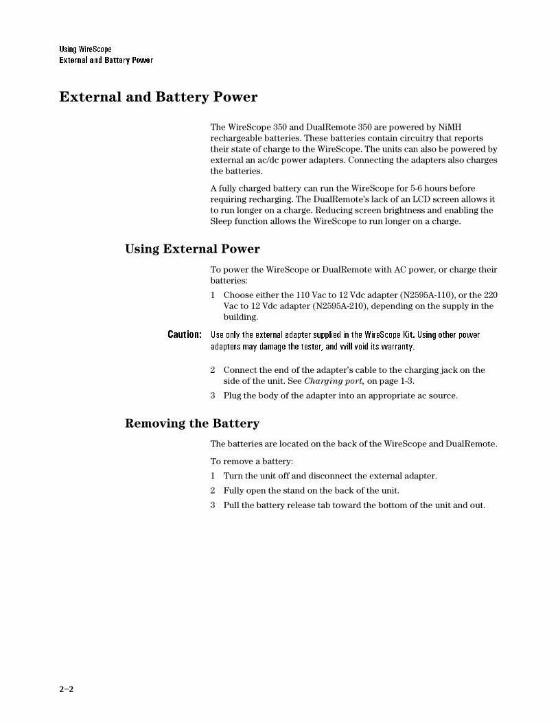
The WireScope talksets have two controls:
• The thumbwheel in the inside curve of the control housing controls the earpiece volume.
• The switch on the outside curve of the control housing switches the microphone off.
(DUSKRQHYROXPH
0LFURSKRQHPXWHVZLWFK

2−6
8VLQJ:LUH6FRSH8VLQJ&RPSDFW)ODVK&DUGV
Using CompactFlash™ Cards
The WireScope 350 can use CompactFlash™ cards for storing large amounts of test data, for transferring data to a PC, and for installing new software.
Installing CompactFlash™ Cards
To install a CompactFlash™ card:
1 Find the CompactFlash™ card slot in the bottom of the WireScope 350. See CompactFlash™ Slot, on page 1-3, for the location of the slot.
2 Insert the CompactFlash™ card into the slot.(If the card does not go in easily, make sure it is oriented correctly with the lip on the bottom.)
3 The WireScope detects the card, and asks if you want to configure the card.
Configuring CompactFlash™ Cards
When a CompactFlash™ card is inserted in the WireScope 350, the tester detects it and displays a window asking if you want to configure the card.
To configure an installed CompactFlash™ card:
1 Insert the card in the slot at the bottom of the WireScope. The Storage window opens.

8VLQJ:LUH6FRSH8SJUDGLQJWKH:LUH6FRSH6RIWZDUH
2−7
2 On the Storage window, press Yes. The Storage Setup screen displays.
3 A screen describing the configuration procedure displays. The configuration executes in steps.
4 When the progress bar shows 100%, press OK. The WireScope 350 will automatically change the Save to: setting on the System Settings to CFlash Card.
Upgrading the WireScope Software
The latest WireScope software is available on the Agilent WireScope Website.
To download the software:
1 Using the Web browser on a PC, go to http://wirescope.comms.agilent.com/
2 Click on the link for “The Latest Software Package for your WireScope/FrameScope Product.”
3 Complete the registration page, and follow the instructions.
See the ScopeData Pro User’s Guide for instructions on installing the new software in the WireScope and DualRemote.

2−8
8VLQJ:LUH6FRSH9LHZLQJ6RIWZDUHDQG+DUGZDUH9HUVLRQ,QIRUPDWLRQ
Viewing Software and Hardware Version Information
To see the software and hardware revision levels, complete the following steps:
1 On the main menu, press the System button. The System Settings screen appears.
2 On the System Settings screen, press System Information, then press the View button. The System Information screen appears.
The System Information screen displays serial numbers and hardware and software version numbers for all of the key subsystems of your WireScope 350 test set.
The WireScope 350 and DualRemote 350 windows each consist of three parts:
• The upper section shows the serial number, software revision level, and boot revision level of the device.
• The middle section shows the hardware revision level of the host module, which contains the user interface and PC interface connections
• The lower section shows the hardware revision level of the test module.
To view information for the last used DualRemote 350, press the DualRemote tab.

8VLQJ:LUH6FRSH7KH6\VWHP6HWWLQJV0HQX
2−9
The System Settings Menu
The System Settings screen is a menu of controls for configuring and viewing information about the WireScope 350.
To open one of the System Settings tools:
1 Press System on the Main Menu or Expert Mode Main Menu. The System Settings screen displays.
2 Press the desired tool, then press Edit or View. (The label on the large button near the bottom of the screen changes with different selections.) The selected tool’s screen displays.
System Information: The System Information screen displays information about the WireScope and DualRemote hardware and software.
Save To: Opens a screen for choosing the destination for saved test results; internal flash memory or CompactFlash™ card.
Power: Opens the Battery Status screen which shows the charge state of the batteries in the WireScope and DualRemote.
Time and Date: This screen has controls for setting the date and time on the WireScope.
User Interface: The User Interface Setup screen has controls for:
• Selecting length units
• Enabling and disabling Expert Mode
• Turning the speaker on and off
• Turning the touch-click sounds on and off
• Enabling and configuring the Sleep Timeout function
• Setting the screen brightness

2−10
8VLQJ:LUH6FRSH7KH6\VWHP6HWWLQJV0HQX
Operators: The Operator Setup screen has controls for entering the names and locations of the technicians using the WireScope and DualRemote.
Calibrate Touchscreen: This screen guides you through a calibration of the touchscreen. Make sure you have a stylus available before entering this function.
Serial Baud Rate: The Serial Baud Rate Setup screen selects one of three data transfer rates for communication with a PC.
Restore Default Settings: This screen lets you clear the operator list and custom limits. It also changes all settings back to a known state, which is it’s main function.
Calibration Information: This screen displays the serial numbers of the WireScope 350 and DualRemote 350, the date they were calibrated at the factory, and the date they were last calibrated in the field.
Autoprint: This screen turns autoprinting on and off. This should be turned on if you wish to print labels on an attached Brady TLS2200 printer after each test record is saved.
Demo Mode: This screen turns Demo mode on and off. Demo mode is useful when learning to use the WireScope and does not reflect the actual cable/run attached to the WireScope.

8VLQJ:LUH6FRSH7KH'DWDEDVH0HQX
2−11
The Database Menu
The Database screen is a menu button that leads to five databases:
• The Tests database contains saved test results.
• Database Reports are summaries of key statistics for saved test results, by site.
• The Site database contains tools for viewing, editing, and creating site configurations.
• The Cable Specs database contains tools for viewing, selecting, and creating cable types by manufacturer.
• The Connecting Hardware database contains tools for viewing, selecting, and creating connector types by manufacturer.
To display the Database screen:
1 On the Main Menu, press Database. The Database screen displays.
2 To view or edit one of the databases, press its button on the menu.

2−12
8VLQJ:LUH6FRSH3ULQWLQJ/DEHOV
Printing Labels
Printing Labels On Site
The WireScope 350 can print labels directly to a Brady TLS2200 label printer. The labeling parameters are set using the procedure Choosing
the Labeling Format, on page 3-6. When the WireScope is configured as described in the following procedure, a label for the tested cable will be printed after saving a test result.
To configure the WireScope 350 to print to the Brady label printer:
1 On the Main Menu, press System. The System Settings screen displays.
2 On the System Settings screen, press Autoprint, then Edit. The Printer Setup screen displays.
3 Press Autoprint to enable the Autoprint function. A checkmark shows that the function is enabled.

8VLQJ:LUH6FRSH3ULQWLQJ/DEHOV
2−13
4 Connect the N2605A-050 interface cable to the serial ports of the WireScope 350 and Brady TLS2200.
5 Turn the Brady printer on.
6 Press the Func and Exit keys on the printer simultaneously. This sets the printer to Peripheral mode.
Printing Labels from a PC
Refer to the ScopeData Pro User’s Guide for instructions on printing labels using a PC.

2−14
8VLQJ:LUH6FRSH3ULQWLQJ/DEHOV
3−1Agilent Technologies
3Certifying Copper Cabling
Copper Testing Overview 3-2
Calibrating the Tester 3-2
Setting Up an Autotest 3-4
Opening the Setup Menu 3-4
Choosing the Profile 3-4
Choosing the Standard 3-4
Entering the Site Name 3-5
Choosing the Labeling Format 3-6
Choosing the Cable Type 3-14
Choosing the Connector Type 3-16
Choosing the Cable Pairing Convention 3-17
Entering the Operator Names 3-18
Running an Autotest 3-20

3−2
&HUWLI\LQJ&RSSHU&DEOLQJ&RSSHU7HVWLQJ2YHUYLHZ
Copper Testing Overview
This chapter describes how to certify twisted-pair copper cabling. The procedures in this chapter are sufficient for most copper certification jobs. If the requirements of the job are not addressed here, refer to Chapter 6, Expert Mode for Copper Testing.
Calibrating the Tester
Before you begin a test, the WireScope and DualRemote pair must be calibrated. Calibration allows the WireScope to compensate for slight anomalies in its measurement hardware or that of the companion DualRemote unit.
1 Connect the WireScope 350 and DualRemote 350 in either of the configurations shown below.
OR
&KDQQHO
3UREH
/LQN
3UREH
3UHFLVLRQ&DOLEUDWLRQ&DEOH
&KDQQHO
3UREH
/LQN
3UREH

&HUWLI\LQJ&RSSHU&DEOLQJ&DOLEUDWLQJWKH7HVWHU
3−3
2 On the main menu, press Calibration.
3 Follow the onscreen instructions to complete the calibration.
1RWH 7RWHVWOLQNFRQILJXUDWLRQVWR&DWHJRU\&ODVV(RUKLJKHU$JLOHQWUHFRPPHQGVFDOLEUDWLQJZLWKWKHSUHFLVLRQFDOLEUDWLRQFDEOH

3−4
&HUWLI\LQJ&RSSHU&DEOLQJ6HWWLQJ8SDQ$XWRWHVW
Setting Up an Autotest
The tester must be configured for testing at each site by completing the following procedures.
Opening the Setup Menu
1 On the Main Menu, press Setup. The Autotest Setup screen displays.
Choosing the Profile
The WireScope 350 normally displays one or two limit options on the Main Menu, based upon the profile selected. If None is selected, then the two limit options are dependent upon the Standard selected. If the Standard is TIA-568B, then the two limit options are Category 5E and Category 6. Otherwise Class D and Class E are displayed. If the profile for a specific test is selected, then only that test choice is displayed. To change the profile:
1 On the Autotest Setup screen, press Profile, then Edit. The Profile Setup screen displays.
2 Press None, or the profile of choice, then press OK. The Autotest Setup screen will then show your selected profile.
Choosing the Standard
The WireScope 350 normally tests to the TIA-568B standard. (For detailed information about test standards, please visit the website at: http://wirescope.comms.agilent.com/ ) To test to a different standard, follow these steps:
1RWH 7KH3URILOHPXVWEHVHWWR1RQHLQRUGHUWRFKDQJHWKH6WDQGDUG
.

&HUWLI\LQJ&RSSHU&DEOLQJ6HWWLQJ8SDQ$XWRWHVW
3−5
1 On the Autotest Setup screen, press Standard, then Edit. The Standard Setup screen displays.
2 Select the desired standard, then press OK. The Autotest Setup screen will then show the selected standard. The selected standard is applied to all subsequent tests.
Entering the Site Name
The site name identifies the group of settings used on a job, and can be applied to test records for that site.
To enter the site name:
1 On the Autotest Setup screen, press Site, then press Edit. The Site Setup screen displays.

3−6
&HUWLI\LQJ&RSSHU&DEOLQJ6HWWLQJ8SDQ$XWRWHVW
2 Select Create a New Site Name, then press Next. (The OK button changes to a Next button when you select Create a New Site
Name.) The screen changes, to allow naming the site.
1RWH 7RFKDQJHWKHQDPHRUODEHOLQJIRUPDWIRUDQH[LVWLQJVLWHSUHVVWKHVLWHQDPHRQWKHOLVWWKHQVHOHFW(GLW9LHZDQGSUHVV1H[W
3 Press the icon under (QWHU1HZ6LWH1DPH The onscreen keyboard opens.
4 Press the keyboard keys to enter the site name, then press OK. The keyboard closes.
Choosing the Labeling Format
The labeling format specifies the scheme used to label test records for that site. This format is applied to the test report and to labels printed for the job. There are three label format options:
• Simple has only one field, such as ‘cable number”. See page 3–7 for the Simple format configuration procedure.
• TIA-606-A complies with the TIA-606-A standard. See page 3–9 for the TIA-606-A format configuration procedure.
• Hierarchical has multiple fields, for designations such as Building, Floor, Wall Plate, and Jack Number. See page 3–11 for the Hierarchical format configuration procedure.

&HUWLI\LQJ&RSSHU&DEOLQJ6HWWLQJ8SDQ$XWRWHVW
3−7
1 On the Site Setup screen, press the preferred labeling format, then press Next.
Simple Label Format
When you choose the Simple labeling format, the following screen displays:
To configure the simple labeling format:
1 If you want the numbers on the labels to increase automatically with each new label and test, press Enable Auto-Increment so that a checkmark appears, as in the figure above.

3−8
&HUWLI\LQJ&RSSHU&DEOLQJ6HWWLQJ8SDQ$XWRWHVW
2 To set the beginning number to other than 1, press the Enter Start
Value field. The onscreen keyboard opens.
3 Press the backspace arrow to erase the number in the display, then press the number keys to enter the new starting number. Press OK. The keyboard closes, and the new starting number appears in the Enter Start Value field.
4 To set the number of cable runs to label and test, press the Enter
End Value field. The onscreen keyboard opens.
5 Press the backspace arrow to erase the number in the display, if any, then press the number keys to enter the new number. Press OK. The keyboard closes, and the new ending number appears in the Enter
End Value field.
6 Press OK. The Autotest Setup screen displays.

&HUWLI\LQJ&RSSHU&DEOLQJ6HWWLQJ8SDQ$XWRWHVW
3−9
TIA-606-A Label Format
When you choose the TIA-606-A labeling format and press Next, the following screen displays:
There are three formatting options within the TIA-606-A standard:
• Class 1 and Class 2 have fields for Floor, Telecom Room, Panel, and Position.
• Class 3 has fields for Building, Floor, Telecom Room, Panel, and Position.
The default Auto-Increment and number settings can be used, or the settings can be changed using the following procedures.
To configure the TIA-606-A labeling format:
1 Press Class 1 or Class 2 if there is only one building on the site. Press Class 3 if the site includes more than one building. Press Next. The Site Setup screen changes to show the fields in the label, the

3−10
&HUWLI\LQJ&RSSHU&DEOLQJ6HWWLQJ8SDQ$XWRWHVW
Auto-Increment settings for the field highlighted, and the start and end values for the field highlighted.
2 If you want the numbers for any field to increase automatically with each new label and test, highlight that field, then press Enable
Auto-Increment so that a checkmark appears, as in the figure above.
3 To set the beginning number for a field to other than 1, highlight the category name, then press the Enter Start Value field. The onscreen keyboard opens.
4 Press the backspace arrow to erase the number in the display, then press the number or letter keys to enter the new starting value. Press OK. The keyboard closes, and the new starting value appears in the Enter Start Value field.

&HUWLI\LQJ&RSSHU&DEOLQJ6HWWLQJ8SDQ$XWRWHVW
3−11
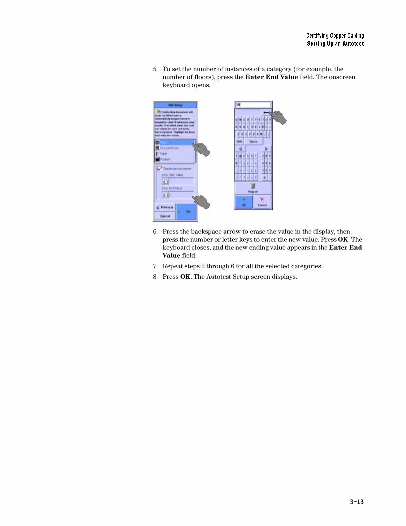
5 To set the number of instances of a category (for example, the number of floors), press the Enter End Value field. The onscreen keyboard opens.
6 Press the backspace arrow to erase the value in the display, then press the number or letter keys to enter the new value. Press OK. The keyboard closes, and the new ending value appears in the Enter End
Value field.
7 Repeat steps 2 through 6 for all the selected categories.
8 Press OK. The Autotest Setup screen displays.
Hierarchical Label Format
When you choose the Hierarchical labeling format, the following screen displays:
Checkmarks indicate fields that appear in the labels. Yellow tags next to the categories indicate that automatic number incrementing is enabled for that field.

3−12
&HUWLI\LQJ&RSSHU&DEOLQJ6HWWLQJ8SDQ$XWRWHVW
To configure the hierarchical labeling format:
1 Press a category to check it for inclusion in the label, or to uncheck it so it does not appear. When all the desired categories are checked, press Next. The Site Setup screen changes to show the selected categories.
2 If you want the numbers for any field to increase automatically with each new label and test, press the category, then press Enable
Auto-Increment so that a checkmark appears, as in the figure above.
3 To set the beginning number for a field to other than 1, press the category name, then press the Enter Start Value field. The onscreen keyboard opens.
4 Press the backspace arrow to erase the number in the display, then press the number or letter keys to enter the new starting value. Press OK. The keyboard closes, and the new starting value appears in the Enter Start Value field.
&HUWLI\LQJ&RSSHU&DEOLQJ6HWWLQJ8SDQ$XWRWHVW
3−13
5 To set the number of instances of a category (for example, the number of floors), press the Enter End Value field. The onscreen keyboard opens.
6 Press the backspace arrow to erase the value in the display, then press the number or letter keys to enter the new value. Press OK. The keyboard closes, and the new ending value appears in the Enter End
Value field.
7 Repeat steps 2 through 6 for all the selected categories.
8 Press OK. The Autotest Setup screen displays.

3−14
&HUWLI\LQJ&RSSHU&DEOLQJ6HWWLQJ8SDQ$XWRWHVW
Choosing the Cable Type
Cable from different manufacturers has different transmission characteristics. The WireScope 350 compensates for those differences if you tell it what cable is used on the job. A solid black cable spool icon indicates a shielded cable, a grey cable spool icon indicates an unshielded cable.
1 On the Autotest Setup screen, press the cable spool icon, then press Edit. The Cable Setup screen displays.
1RWH 7KHVFUROOEDURQWKHULJKWRIWKHVFUHHQVKRZVWKHORFDWLRQRIWKHGDWDVKRZQDQGLVQRWDIXQFWLRQDOVFUROOEDU7RVFUROOXVHWKHVFUROOEXWWRQDWWKHORZHUULJKWRIWKH:LUH6FRSH
2 Select the cable manufacturer, and press Next. The Cable Database screen displays.
3 Select a cable on the list, and press OK. The Autotest Setup screen displays, with the selected cable type next to the cable spool icon. If you do not see the cable on the list, see the next section.
Adding a new cable type
If you have a cable which is not in the cable database, you can add a new cable description to the database.
1 If the manufacturer is not present, leave the manufacturer as Unspecified. If the manufacturer is present on the list, select it, then press Next. The Cable Database screen is displayed. In either case, you will be offered stored descriptions of cable types. If one of the stored descriptions matches the cable being tested, select it, then press OK.
2 If not, highlight Add New Description, and press Next.
3 Enter the name to be added to the database and press Next.

&HUWLI\LQJ&RSSHU&DEOLQJ6HWWLQJ8SDQ$XWRWHVW
3−15
4 Enter the pair count, cable construction, and impedance (default selections are available) and press Next.
5 Enter the nominal velocity of propagation (NVP) for each pair, if known, or select Calculate NVP from length. If you need to calculate NVP from length, attach at least 50 feet (15 meters) of cable to the WireScope with the far end disconnected, enter the measured length, and press Calculate. The NVP as a percentage of the speed of light will be supplied in the NVP window. Press Next.
6 Select the target performance grade of the cable, if known, and press OK. The Autotest Setup screen displays, with the new cable type next to the cable spool icon.

3−16
&HUWLI\LQJ&RSSHU&DEOLQJ6HWWLQJ8SDQ$XWRWHVW
Choosing the Connector Type
Connectors from different manufacturers have different transmission characteristics. The WireScope 350 compensates for those differences, if you tell it what connectors are used on the job.
1 On the Autotest Setup screen, press the connector icon, then press Edit. The Connector Setup screen displays.
1RWH 7KHVFUROOEDURQWKHULJKWRIWKHVFUHHQVKRZVWKHORFDWLRQRIWKHGDWDVKRZQDQGLVQRWDIXQFWLRQDOVFUROOEDU7RVFUROOXVHWKHVFUROOEXWWRQDWWKHORZHUULJKWRIWKH:LUH6FRSH
2 Press the manufacturer of the connector, then Next. A list of that manufacturer’s connectors displays.
3 Press the name of the connector, then press OK. The Autotest Setup screen displays, with the selected connector type next to the connector icon. If you do not see the connector on the list, see the next section
Adding a new connector type
If you have a connector which is not in the connector database, you can add a new connector description to the database.
1 If the manufacturer is not present, leave the manufacturer as Unspecified. If the manufacturer is present on the list, select it, then press Next. The Connector Setup screen is displayed. In either case, you will be offered stored descriptions of connector types. If one of the stored descriptions matches the connector being tested, select it, then press OK.
2 If not, highlight Add New Description, and press Next.
3 Enter the name to be added to the database and press Next.
4 Select whether the connector is shielded or not and press Next.

&HUWLI\LQJ&RSSHU&DEOLQJ6HWWLQJ8SDQ$XWRWHVW
3−17
5 Select the performance grade of the connector, if known, and press OK. The Autotest Setup screen displays, with the new connector type nest to the connector icon.
Choosing the Cable Pairing Convention
To identify the correct pair in the test results, the WireScope must be told what cable pairing convention is used. For example, if the 3,6 pair fails a test, it would be “Pair 2” if using T568A pairing, but it would be “Pair 3” if using T568B pairing.
1 On the Autotest Setup screen, press Cable Pairing, then press Edit. The Cable Pairing Setup screen displays.
2 Press the cable pairing convention used on the job, then press OK. The Autotest Setup screen displays, with the cable pairing convention named.

3−18
&HUWLI\LQJ&RSSHU&DEOLQJ6HWWLQJ8SDQ$XWRWHVW
Entering the Operator Names
The names of the technicians performing the tests can be entered, and will appear on the test report.
To enter the test technicians’ names:
1 On the Main Menu, press System. The System Settings screen displays.
2 Press Operators, then press Edit. The Operator Setup screen displays.
3 Choose the WireScope unit’s testing location, either Telecom Room, Outlet, or Other.
4 Press the WireScope Operator field. The onscreen keyboard opens, with “WireScope Operator” at the top or a list of previously entered names will appear with the keyboard and keypad buttons available.
&HUWLI\LQJ&RSSHU&DEOLQJ6HWWLQJ8SDQ$XWRWHVW
3−19
5 Pick a name from the list or press the keyboard keys to enter the name of the technician using the WireScope, then press OK. The keyboard closes, and the technician’s name appears in the WireScope Operator field of the Operator Setup screen.
6 Choose the DualRemote unit’s testing location, either Telecom
Room, Outlet, or Other.
7 Press the DualRemote Operator field. The onscreen keyboard opens, with “DualRemote Operator” at the top or a list of previously entered names will appear with the keyboard and keypad buttons available.
8 Pick a name from the list or press the keyboard keys to enter the name of the technician using the DualRemote, then press OK. The keyboard closes, and the technician’s name appears in the DualRemote Operator field of the Operator Setup screen.
9 Press OK. The System Settings screen displays.

3−20
&HUWLI\LQJ&RSSHU&DEOLQJ5XQQLQJDQ$XWRWHVW
Running an Autotest
To run an autotest:
1 If this is the first test of the day or after a long break, calibrate the tester. See Calibrating the Tester, on page 3-2.
2 Connect the WireScope 350 and Dual Remote 350 to the ends of the circuit needing certification.
3 On the WireScope Main Menu, press the button identifying the selected test. The test executes.
1RWH ,IQRFKDQJHVZHUHPDGHWRWKHGHIDXOWWHVWLQJVWDQGDUGVRUSURILOHVWKH0DLQ0HQXVKRZVEXWWRQVIRU&DWHJRU\(DQG&DWHJRU\WHVWV,IWKH3URILOHKDVEHHQFKDQJHGWKH0DLQ0HQXVKRZVRQO\RQHWHVWEXWWRQLQGLFDWLQJWKHQHZWHVWSURILOH
4 If the autotest passes, the screen will look like this:
5 To save the test results, see Chapter 5 Saving Test Results.
4−1Agilent Technologies
4Certifying Fiber Cabling
Fiber Testing Overview 4-2
Calibrating the Tester 4-4
Calibrating for Double-Ended Testing 4-4
Calibrating for Single-Ended Testing 4-7
Setting Up an Autotest 4-9
Opening the Settings Menu 4-9
Choosing the Test Configuration 4-10
Setting the Loss Limit 4-10
Setting the Length Limit 4-13
Choosing the Network Limit 4-14
Entering the Site Name 4-15
Choosing the Cable Type 4-16
Setting the Modal Bandwidth 4-18
Choosing the Connector Type 4-18
Entering the Operator Names 4-20
Running an Autotest 4-22

4−2
&HUWLI\LQJ)LEHU&DEOLQJ)LEHU7HVWLQJ2YHUYLHZ
Fiber Testing Overview
This chapter describes how to certify optical fiber cabling. The procedures in the chapter are sufficient for most fiber certification jobs. If the requirements of the job are not addressed here, refer to Chapter 7, Expert Mode for Fiber Testing.
Three connection configurations are available for optical fiber certification testing.
Double-Ended, Single Fiber
Double-ended single fiber configuration tests one fiber, using two Fiber SmartProbes. For single fiber testing the fiber must go from the transmitter/laser source on the DualRemote to the detector on the WireScope. When the 850nm multimode probe is in the DualRemote, the units can be as much as 4 km apart. When the 1300nm multimode probe is in the DualRemote, the units can be as much as 10 km apart. When singlemode probes are used, the WireScope and DualRemote can be as much as 50 km apart. All maximum lengths are barring excessive loss.
Double-Ended, Fiber Pair
Double-ended fiber pair configuration tests two fibers, using two Fiber SmartProbes. When multimode probes are used, the WireScope and DualRemote can be as much as 4 km apart. When singlemode probes are used, the WireScope and DualRemote can be as much as 50 km apart. All maximum lengths are barring excessive loss.

&HUWLI\LQJ)LEHU&DEOLQJ)LEHU7HVWLQJ2YHUYLHZ
4−3
Single-Ended, Fiber Pair (Loopback)
Single-ended loopback configuration tests two fibers, using one Fiber SmartProbe and a fiber test jumper. When an 850nm multimode probe is used, the WireScope and the fiber test jumper can be as much as 2 km apart, or 4 km overall fiber length. When an 1300nm multimode probe is used, the WireScope and the fiber test jumper can be as much as 5 km apart, or 10 km overall fiber length.When singlemode probes are used, the WireScope and fiber test jumper can be as much as 25 km apart, or 50 km overall. All maximum lengths are barring excessive loss.
1RWH 6LQJOHPRGH)LEHU6PDUW3UREHVXVHDODVHUOLJKWVRXUFHWKDWUHTXLUHVZDUPLQJXSEHIRUHXVH%HIRUHFDOLEUDWLQJRUWHVWLQJZLWKVLQJOHPRGHILEHUSUREHVDOZD\VFRQQHFWWKHSUREHVWXUQRQWKH:LUH6FRSHDQG'XDO5HPRWHLIXVHGDQGZDLWILYHPLQXWHVIRUPRVWDFFXUDWHUHDGLQJV
)LEHUWHVWMXPSHU

4−4
&HUWLI\LQJ)LEHU&DEOLQJ&DOLEUDWLQJWKH7HVWHU
Calibrating the Tester
Before you begin a test, the WireScope and DualRemote pair must be calibrated. Calibration allows the WireScope to compensate for slight anomalies in its measurement hardware or that of the companion DualRemote unit.
Calibrating for Double-Ended Testing
Method A
This method is commonly called Method A or the 2-jumper method and is usually recommended for singlemode fiber.
1RWH 8VHWKHVDPHFDOLEUDWLRQPHWKRGZKHWKHU\RXDUHWHVWLQJWZRILEHUVRUMXVWRQHILEHU
1 Insert a Fiber SmartProbe+ in the WireScope, and a Fiber SmartProbe+ in the DualRemote. They should both be either multimode or singlemode.
1RWH 6LQJOHPRGH)LEHU6PDUW3UREHVXVHDODVHUOLJKWVRXUFHWKDWUHTXLUHVZDUPLQJXSEHIRUHXVH%HIRUHFDOLEUDWLQJRUWHVWLQJZLWKVLQJOHPRGHILEHUSUREHVDOZD\VFRQQHFWWKHSUREHVWXUQRQWKH:LUH6FRSHDQG'XDO5HPRWHLIXVHGDQGZDLWILYHPLQXWHVIRUPRVWDFFXUDWHUHDGLQJV
2 Connect duplex test jumpers to the two Fiber SmartProbes.
3 Connect the test jumpers to each other, using two couplers. Connect the WireScope transmitter to the DualRemote detector, and vice versa.
4 Turn on the WireScope and DualRemote.
The WireScope detects a Fiber SmartProbe+, and displays the following window:
.

&HUWLI\LQJ)LEHU&DEOLQJ&DOLEUDWLQJWKH7HVWHU
4−5
5 On the Fiber Main Menu, press Calibration. The Fiber Calibration screen displays.
6 Choose Double Ended, and press Next. The Fiber Detection screen displays.
7 When the message below the diagram reads, “Ready to Calibrate,” press OK. The Calibration window opens.
8 When the window reads, “Calibration Successful,” press OK in the window. The Fiber Main Menu displays. Remove the couplers and use the coupler ends of the test jumpers when changing connections. Leave the test jumper connections to the Fiber SmartProbes intact.
Method B
Method B or the 1-jumper method is usually recommended for multimode fiber.

4−6
&HUWLI\LQJ)LEHU&DEOLQJ&DOLEUDWLQJWKH7HVWHU
1 Insert a Fiber SmartProbe+ in the WireScope and a Fiber SmartProbe+ in the DualRemote. They should both be multimode.
2 Connect a single fiber of each of two duplex test jumpers to the two Fiber SmartProbes+ with the transmitter of each connected to the detector of the other with no coupler.
3 Turn on the WireScope and DualRemote.
4 On the Fiber Main Menu, press Calibration. The Fiber Calibration screen displays as above.
5 Choose Double Ended, and press Next. the Fiber Detection screen displays as above.
6 When the message below the diagram reads, “Ready to Calibrate,” press OK. The Calibration window opens.
7 When the window reads, “Calibration Successful,” press OK in the window. The Fiber Main Menu displays. Leave the transmitter connection to the Fiber SmartProbes intact. Remove both detector connections and replace with the previously unused fiber of the duplex test jumper on each probe.
Method C
Method C is recommended for multi-fiber and small form factor (SFF) connectors.
1RWH %HFDXVHWKHPXOWLILEHU6))FRQQHFWRUVDUHSRODUL]HGFRQQHFWRUVHQVXUHWKDW\RXKDYHVHOHFWHGWKHSURSHUFRQQHFWRUW\SHLQWKH$XWRWHVW6HWXSVFUHHQVHH &KRRVLQJWKH&RQQHFWRU7\SH RQSDJH
1 Insert a Fiber SmartProbe+ in the WireScope and a Fiber SmartProbe+ in the DualRemote. They should both be either singlemode or multimode.
1RWH 6LQJOHPRGH)LEHU6PDUW3UREHVXVHDODVHUOLJKWVRXUFHWKDWUHTXLUHVZDUPLQJXSEHIRUHXVH%HIRUHFDOLEUDWLQJRUWHVWLQJZLWKVLQJOHPRGHILEHUSUREHVDOZD\VFRQQHFWWKHSUREHVWXUQRQWKH:LUH6FRSHDQG'XDO5HPRWHLIXVHGDQGZDLWILYHPLQXWHVIRUPRVWDFFXUDWHUHDGLQJV
2 Connect special ST or SC to multi-fiber/SFF test jumpers to the two Fiber SmartProbes. These special transition jumpers are available from the connector manufacturers.
3 Connect the test jumpers to each other, using a special reference jumper which mates with the multi-fiber/SFF connector. Special reference jumpers are manufacturer specific. Contact the connector manufacturer for details. Connect the WireScope transmitter to the DualRemote detector, and vice versa.
4 Turn on the WireScope and DualRemote, if necessary.
5 On the Fiber Main Menu, press Calibration. The Fiber Calibration screen displays as above.
6 Choose Double Ended, and press Next. the Fiber Detection screen displays as above.
7 When the message below the diagram reads, “Ready to Calibrate,” press OK. The Calibration window opens.
&HUWLI\LQJ)LEHU&DEOLQJ&DOLEUDWLQJWKH7HVWHU
4−7
8 When the window reads, “Calibration Successful,” press OK in the window. The Fiber Main Menu displays. Remove the reference jumper to start testing.
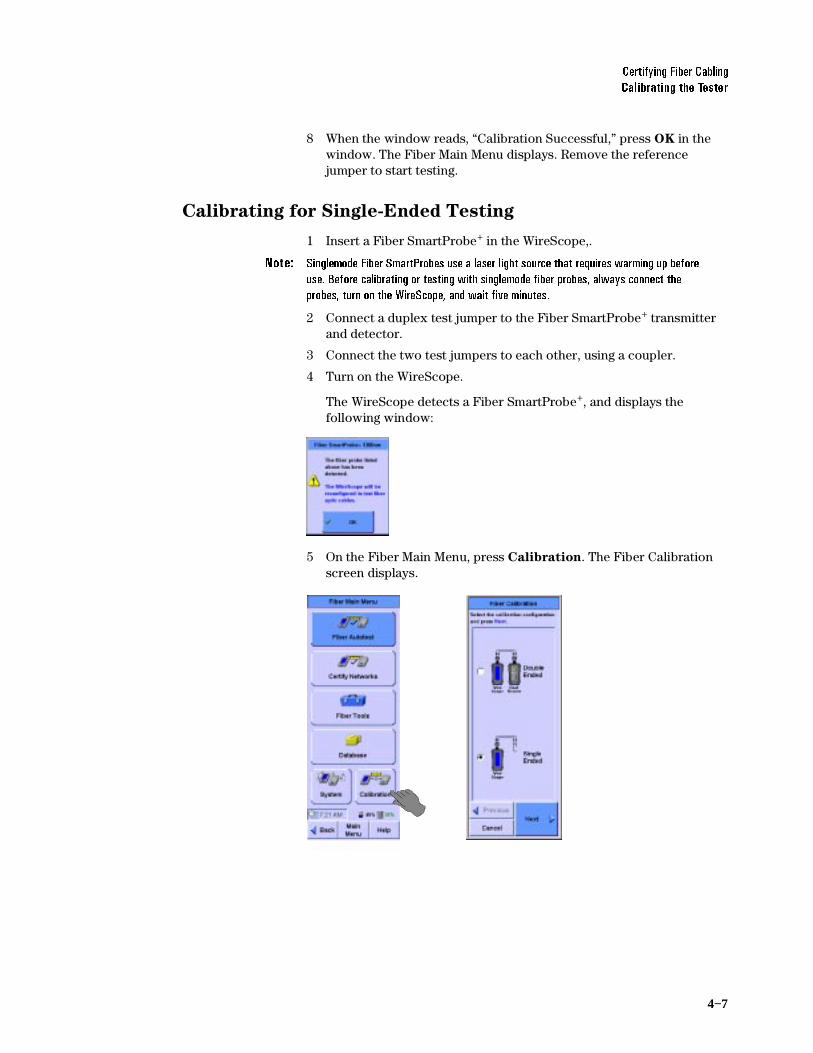
Calibrating for Single-Ended Testing
1 Insert a Fiber SmartProbe+ in the WireScope,.
1RWH 6LQJOHPRGH)LEHU6PDUW3UREHVXVHDODVHUOLJKWVRXUFHWKDWUHTXLUHVZDUPLQJXSEHIRUHXVH%HIRUHFDOLEUDWLQJRUWHVWLQJZLWKVLQJOHPRGHILEHUSUREHVDOZD\VFRQQHFWWKHSUREHVWXUQRQWKH:LUH6FRSHDQGZDLWILYHPLQXWHV
2 Connect a duplex test jumper to the Fiber SmartProbe+ transmitter and detector.
3 Connect the two test jumpers to each other, using a coupler.
4 Turn on the WireScope.
The WireScope detects a Fiber SmartProbe+, and displays the following window:
5 On the Fiber Main Menu, press Calibration. The Fiber Calibration screen displays.

4−8
&HUWLI\LQJ)LEHU&DEOLQJ&DOLEUDWLQJWKH7HVWHU
6 Choose Single Ended, and press Next. The Fiber Detection screen displays.
7 When the message below the diagram reads, “Ready to Calibrate,” press OK. The Calibration window opens.
8 When the window reads, “Calibration Successful,” press OK in the window. The Fiber Main Menu displays.
&HUWLI\LQJ)LEHU&DEOLQJ6HWWLQJ8SDQ$XWRWHVW
4−9
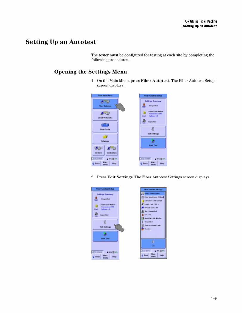
Setting Up an Autotest
The tester must be configured for testing at each site by completing the following procedures.
Opening the Settings Menu
1 On the Main Menu, press Fiber Autotest. The Fiber Autotest Setup screen displays.
2 Press Edit Settings. The Fiber Autotest Settings screen displays.

4−10
&HUWLI\LQJ)LEHU&DEOLQJ6HWWLQJ8SDQ$XWRWHVW
Choosing the Test Configuration
To choose either single-ended or double-ended testing:
1 On the Fiber Autotest Settings screen, press Setup, then press Edit. The test Configuration Setup screen displays.
2 Press either Double Ended or Single Ended, then press OK. The Fiber Autotest Settings screen displays, with the selected configuration next to Setup.
Setting the Loss Limit
To set the loss limit for fiber testing:
1 On the Fiber Autotest Settings screen, press Loss Limit, then Edit. The Loss Limit Setup screen displays.

&HUWLI\LQJ)LEHU&DEOLQJ6HWWLQJ8SDQ$XWRWHVW
4−11
2 Select either Overall Budget Method or Loss/Length Method, then press Next. Continue by completing the steps in the matching section that follows.
Overall Budget Method
Overall Budget Method configures a fixed loss limit value for each applicable wavelength. If a multimode SmartProbe is installed, you are asked to specify overall loss budgets for 850 nm and 1300 nm wavelengths. If a singlemode SmartProbe is installed, you are asked to specify overall loss budgets for 1310 nm and 1550 nm wavelengths.
When you select Overall Budget Method and press Next on the Loss Limit Setup screen, the screen changes to the following:
1 To set the loss limit for a listed wavelength, press the wavelength field. The numeric keypad opens.
2 Press the backspace arrow to erase the displayed value, then enter the new limit value. Press OK. The keypad closes.
3 Press OK. The Fiber Autotest Settings screen displays.

4−12
&HUWLI\LQJ)LEHU&DEOLQJ6HWWLQJ8SDQ$XWRWHVW
Loss/Length Method
When Loss/Length Method is selected, the WireScope 350 calculates the limit based on the length of the cable tested. You can set values for connectors, loss per connector, splices, and loss per splice. The connector and splice losses are added to the loss that is calculated by multiplying the length of the fiber by the loss/Km specification of the selected cable, which is shown at the bottom of the Setup screen.
When you select Loss/Length Method and press Next on the Loss Limit Setup screen, the screen changes to the following:
1 To set any of the variable values, press the variable. The numeric keypad opens.
2 Press the backspace arrow to erase the displayed value, then enter the new variable value. Press OK. The keypad closes.
3 Press OK. The Fiber Autotest Settings screen displays.

&HUWLI\LQJ)LEHU&DEOLQJ6HWWLQJ8SDQ$XWRWHVW
4−13
Setting the Length Limit
To set the length limit for fiber testing:
1 On the Fiber Autotest Settings screen, press Length Limit, then press Edit. The Length Limit Setup screen displays.
2 Press the Fiber Length field. The numeric keypad opens.
3 Press the backspace arrow to erase the displayed value, then enter the new limit value. Press OK. The keypad closes.
4 Press OK. The Fiber Autotest Settings screen displays.

4−14
&HUWLI\LQJ)LEHU&DEOLQJ6HWWLQJ8SDQ$XWRWHVW
Choosing the Network Limit
The WireScope 350 can certify cabling for compliance with the physical medium dependent (PMD) requirements of popular network interface technologies such as Ethernet or ATM. Network certification can be performed in addition to certifying to cabling limits.
A pass result for a particular networking technology indicates that the tested cable run meets the loss and length requirements necessary to successfully support communications between devices of that type.
To choose the network limit:
1 On the Fiber Autotest Settings screen, press Network Limits, then press Edit. The Networks Setup screen displays.
2 Press a limit to choose it. When you have placed check marks next to all types of networks you wish to certify, press OK. The Fiber Autotest Settings screen displays.
&HUWLI\LQJ)LEHU&DEOLQJ6HWWLQJ8SDQ$XWRWHVW
4−15
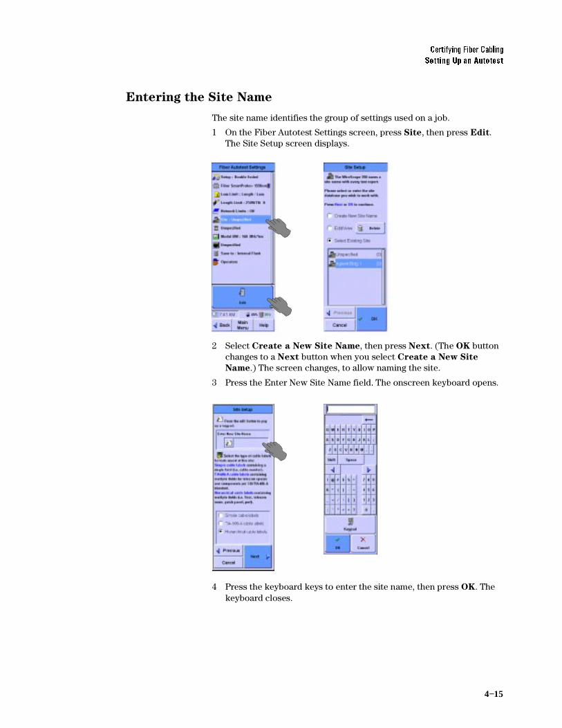
Entering the Site Name
The site name identifies the group of settings used on a job.
1 On the Fiber Autotest Settings screen, press Site, then press Edit. The Site Setup screen displays.
2 Select Create a New Site Name, then press Next. (The OK button changes to a Next button when you select Create a New Site
Name.) The screen changes, to allow naming the site.
3 Press the Enter New Site Name field The onscreen keyboard opens.
4 Press the keyboard keys to enter the site name, then press OK. The keyboard closes.

4−16
&HUWLI\LQJ)LEHU&DEOLQJ6HWWLQJ8SDQ$XWRWHVW
Choosing the Labeling Format
The labeling format for fiber testing is the same as that previously described in Chapter 3, Certifying Copper Cabling. See Choosing the
Labeling Format, on page 3-6 for more information.
Choosing the Cable Type
Cable from different manufacturers has different transmission characteristics. The WireScope 350 compensates for those differences if you tell it what cable is used on the job. The color of the cable spool icon indicates multimode (orange) or singlemode (yellow) fiber.
1 On the Fiber Autotest Settings screen, press the spool icon, then press Edit. The Cable Setup screen displays.
2 Select the cable manufacturer, and press Next. The Cable Database screen displays.
3 Select a cable on the list, and press OK. The Fiber Autotest Setup screen displays, with the selected cable type next to the cable spool icon. If you do not see the cable on the list, see the next section.
Adding a new cable type
If you have a cable which is not in the cable database, you can add a new cable description to the database.
1 If the manufacturer is not present, leave the manufacturer as Unspecified. If the manufacturer is present on the list, select it, then press Next. The Cable Database screen is displayed. In either case, you will be offered stored descriptions of cable types. If one of the stored descriptions matches the cable being tested, select it, then press OK.
2 If not, highlight Add New Description, and press Next.
3 Enter the name to be added to the database and press Next.

&HUWLI\LQJ)LEHU&DEOLQJ6HWWLQJ8SDQ$XWRWHVW
4−17
4 Select the fiber construction that is appropriate and press Next.
5 Enter either the nominal velocity of propagation (NVP) of the fiber cable, OR the fiber cable’s refractive index (default values are presented) and press Next. If you do not know either value, but have a known length of cable, select Calculate NVP from length and select the Test Configuration and press Next.
6 If you are calculating NVP from length, enter the fiber length. You may have to calibrate the tester in the test configuration you have specified, using appropriate test jumpers. There is a Quick Setup button for specifying the test configuration and fiber construction for the NVP measurement. When the proper connection has been made, a Measure button will appear. Press Measure and the NVP as a percentage of the speed of light will be entered in the NVP window. When completed, press Next.
7 Enter the nominal specifications of the fiber. Default values are presented. Press OK and the Fiber Autotest Settings screen will display with the new cable description entered beside the cable spool icon.

4−18
&HUWLI\LQJ)LEHU&DEOLQJ6HWWLQJ8SDQ$XWRWHVW
Setting the Modal Bandwidth
1RWH 0RGDOEDQGZLGWKLVDVHOHFWLRQRQO\DYDLODEOHZLWKPXOWLPRGHILEHU,IDVLQJOHPRGHILEHUFDEOHLVVHOHFWHGDERYHWKLVVHOHFWLRQILHOGLVQRWSUHVHQW
With multimode fiber, the signal can be transmitted in different “modes.” The modal bandwidth is a measurement of the ability of the fiber cable to pass the signal without adding additional attenuation. Modal bandwidth is a rating given to the fiber. The fiber manufacturer should be able to tell what the modal bandwidth of their fiber is. You should then select the proper Modal Bandwidth in the WireScope 350 before running the test. To set the modal bandwidth for optical fiber certification:
1 On the Fiber Autotest Settings screen, press Modal BW, then Edit. The Modal BW Setup screen displays.
2 Choose the modal bandwidth and press OK. The Fiber Autotest Setup screen displays, with the chosen bandwidth next to Modal
BW.
Choosing the Connector Type
Connectors of different types have different transmission characteristics. The WireScope 350 compensates for those differences, if you tell it what connectors are used on the job.

&HUWLI\LQJ)LEHU&DEOLQJ6HWWLQJ8SDQ$XWRWHVW
4−19
1 On the Fiber Autotest Settings screen, press the connector icon, then Edit. The Connector Setup screen displays.
2 Press Next. A list of that connector types displays.
3 Press the type of the connector, then press OK. The Fiber Autotest Setup screen displays, with the selected connector type next to the connector icon. If you do not see the connector on the list, see the next section
Adding a new connector type
If you have a connector which is not in the connector database, you can add a new connector description to the database.
1 If the manufacturer is not present, leave the manufacturer as Unspecified. If the manufacturer is present on the list, select it, then press Next. The Connector Setup screen is displayed. In either case, you will be offered stored descriptions of connector types. If one of

4−20
&HUWLI\LQJ)LEHU&DEOLQJ6HWWLQJ8SDQ$XWRWHVW
the stored descriptions matches the connector being tested, select it, then press OK.
2 If not, highlight Add New Description, and press Next.
3 Enter the name to be added to the database and press Next.
4 Select the fiber connector type from the list of mono-fiber connectors and multi-fiber connectors shown or select Unspecified. Press OK and Fiber Autotest Settings screen displays with the new connector description beside the fiber connector icon.
Entering the Operator Names
The names of the technicians performing the tests can be entered, and will appear on the test report.
To enter the test technicians’ names:
1 On the Fiber Autotest Setup screen, press Operators, then Edit. The Operator Setup screen displays.

&HUWLI\LQJ)LEHU&DEOLQJ6HWWLQJ8SDQ$XWRWHVW
4−21
2 Choose the WireScope unit’s testing location, either Telecom Room, Outlet, or Other.
3 Press the WireScope Operator field. The onscreen keyboard opens, with “WireScope Operator” at the top or a list of previously entered names will appear with the keyboard and keypad buttons available.
4 Press the keyboard keys to enter the name of the technician using the WireScope, then press OK. The keyboard closes, and the technician’s name appears in the WireScope Operator field of the Operator Setup screen.
5 Choose the DualRemote unit’s testing location, either Telecom
Room, Outlet, or Other.
6 Press the DualRemote Operator field. The onscreen keyboard opens, with “DualRemote Operator” at the top or a list of previously entered names will appear with the keyboard and keypad buttons available.
7 Press the keyboard keys to enter the name of the technician using the DualRemote, then press OK. The keyboard closes, and the technician’s name appears in the DualRemote Operator field of the Operator Setup screen.
8 Press OK and press Main Menu. The Fiber Main Menu displays.

4−22
&HUWLI\LQJ)LEHU&DEOLQJ5XQQLQJDQ$XWRWHVW
Running an Autotest
To run an autotest:
1 Connect the WireScope 350 and Dual Remote 350 to the ends of the circuit needing certification.
2 On the WireScope Fiber Main Menu, press Fiber Autotest. The Fiber Autotest Setup screen displays.
3 Press Start Test. The autotest executes.
4 Follow the on screen directions, which may include swapping fiber connections.
1RWH :KHQGLVFRQQHFWLQJILEHUVIRUVZDSSLQJGLVFRQQHFWDWWKHHQGRIWKHWHVWMXPSHUVQRWDWWKH)LEHU6PDUW3UREH
5 To save the test results, see Chapter 5 Saving Test Results.

5−1Agilent Technologies
5Saving Test Results
Test Results Display 5-2
Saving Test Results 5-3
Choosing the Data Storage Location 5-3
Saving the Results 5-4
Viewing Result Details 5-5

5−2
6DYLQJ7HVW5HVXOWV7HVW5HVXOWV'LVSOD\
Test Results Display
When the WireScope completes a test, it displays either a Pass or Fail screen. All the example screens in this chapter are from Category 6 tests; other test result screens are similar.
Both the Pass and Fail screens list the test parameters, with the results of each parameter. On Fail screens, results that failed the test are shown in red.
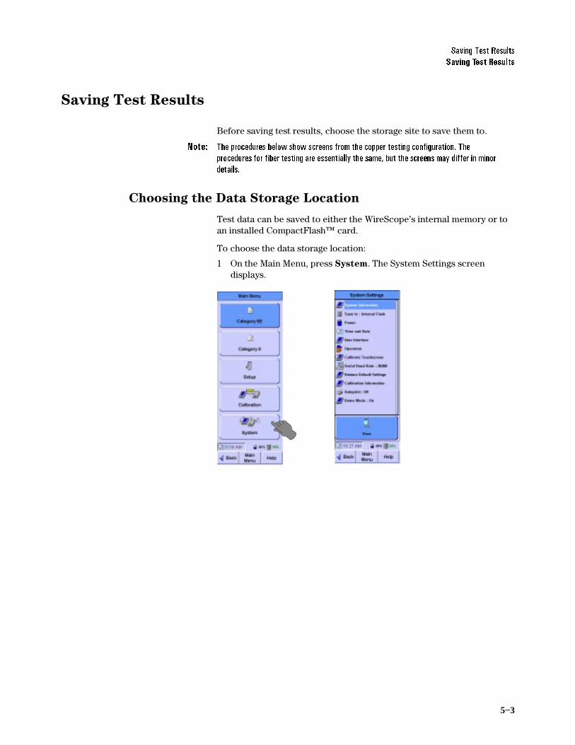
6DYLQJ7HVW5HVXOWV6DYLQJ7HVW5HVXOWV
5−3
Saving Test Results
Before saving test results, choose the storage site to save them to.
1RWH 7KHSURFHGXUHVEHORZVKRZVFUHHQVIURPWKHFRSSHUWHVWLQJFRQILJXUDWLRQ7KHSURFHGXUHVIRUILEHUWHVWLQJDUHHVVHQWLDOO\WKHVDPHEXWWKHVFUHHQVPD\GLIIHULQPLQRUGHWDLOV
Choosing the Data Storage Location
Test data can be saved to either the WireScope’s internal memory or to an installed CompactFlash™ card.
To choose the data storage location:
1 On the Main Menu, press System. The System Settings screen displays.

5−4
6DYLQJ7HVW5HVXOWV6DYLQJ7HVW5HVXOWV
2 On the System Settings screen, press Save To, then press Edit. The Storage Setup screen displays.
3 Select either Internal Flash or CFlash Card.
4 If you chose Internal Flash, press OK. The System Settings screen displays, with “Internal Flash” next to Save To.
5 If you chose CFlash Card, press Next. The Storage Setup screen displays a message about preparing the CompactFlash™ card. The Storage Setup screen displays a list of the steps in preparing the CF card, and a progress bar.
6 When the progress bar shows 100%, press OK. The System Settings screen displays, with “CFlash Card” next to Save To.
Saving the Results
To save the test results for inclusion in certification reports:
.

6DYLQJ7HVW5HVXOWV9LHZLQJ5HVXOW'HWDLOV
5−5
1 After completing a test, press the Save button. The Save Results screen displays.
2 If the cable ID in the display is wrong, press the backspace arrow to erase it, and press the keyboard keys to enter the correct cable ID. For a cable ID with multiple fields, press Shift, then Tab to back up to a prior field, or use your stylus or finger to get to the desired field. An unshifted Tab will move the cursor forward one field.
3 When the label is correct, press the Save button. The WireScope saves the results of the test to the chosen storage site. If you have a multiple-field cable ID, there must be a value in every field, including before the first yellow dot and after the last yellow dot.
Viewing Result Details
A Details button on Pass and Fail screens opens the Test Data screen.

5−6
6DYLQJ7HVW5HVXOWV9LHZLQJ5HVXOW'HWDLOV
The Test Data screen lists the test parameters and indicates passing or failure for each.
To view detailed test data for one of the test parameters:
1 Press the name of the test parameter. The Test Data screen displays buttons appropriate for the selected parameter.
For example, when NEXT is selected, the screen includes Data, Plots, and Locator buttons, while pressing Wiremap shows only the
Data button.
2 To view the Data screen for the selected test parameter, press Data. The Data screen displays.
3 To view the Plots screen for the selected test parameter (if the Plots button is present), press Plots. The Plots screen displays.

6DYLQJ7HVW5HVXOWV9LHZLQJ5HVXOW'HWDLOV
5−7
4 To view the Locator screen for the selected test parameter (if the Locator button is present), press Locator. The Locator screen displays.
Interpreting Test Results Detail Screens
The various test detail screens present test data in different formats, as explained below.
Data Screens
The Data screen shows detail of the selected test parameter results. The examples above show data of a passing test, at left, and a failing one, at right. The data included depends on which parameter is selected. (See steps 2, 3, and 4 of the Viewing Result Details procedure on page 5-5.)

5−8
6DYLQJ7HVW5HVXOWV9LHZLQJ5HVXOW'HWDLOV
The Data screens shown above include a table that displays details of the test results for two twisted pairs of copper cable. To view the results for a different set of twisted pairs, press it on the list.
Plots Screens
Plots screens display test results as plots on a graph. The examples above show plots of a passing test, at left, and a failing one, at right. A smooth red line on the plot indicates the limit boundary between passing and failure. The Worst Margin button places a vertical line on the plot at the frequency where the test results come closest to the pass/fail boundary on passing test plots. On failing test plots, the Worst Margin button places the line at the frequency where the results exceed the acceptable limits the most. You can move the cursor around the plot screen by pressing the area you want to see and then using the scroll rocker to fine tune the location. The frequency of the cursor is displayed and the values in the table correspond to the cursor location.
A chart below the plot shows detailed results of the current location of the cursor at the WireScope and DualRemote, and the limits for the test parameter, as follows:
Data: This is the worst case of the test results at the cursor location.
Limit: The limit of passing results, set when the test standard is chosen at the cursor location.
Margin: The difference between the Data value and the Limit value at the cursor location.
The plots are color coded for different wire pairs. The plot lines displayed can be changed by pressing Settings and selecting All Plots, All Local Plots, All Remote Plots, Worst Case Plot, or Select Single Plot.

6DYLQJ7HVW5HVXOWV9LHZLQJ5HVXOW'HWDLOV
5−9
You can also choose to show plots to 100 MHz, 250 MHz, or 350 MHz as long as the test was run to the frequency selected. See Setting the
Maximum Frequency, on page 6-16.
Locator Screens
Locator screens aid in finding faults on the tested cable. The examples above show Locator screens for a passing test, at left, and a failing one, at right. Note the difference in the plots, where the failing result shows a peak where the failure occurs. The tape measure provides a reading of where the failure occurs. It will be placed on the right-hand side of the screen if showing the distance from the DualRemote. If there are more than one peak, you can press the plot area near the peak and fine tune the location using the scroll rocker to find the exact distance to the peak. By default, the distance shown is how far away the worst test result is from the closest of the WireScope or DualRemote. To see the locator results for the different sets of twisted pair cables, press them on the list.
1RWH )DLOXUHVYHU\QHDUWKHHQGVRIDFDEOHUXQDUHXVXDOO\EHFDXVHRIWHUPLQDWLRQHUURUVVXFKDVDEDGFULPS)DLOXUHVIDUIURPWKHHQGVRIDFDEOHUXQDUHXVXDOO\DIDXOWZLWKWKHFDEOHLWVHOI

5−10
6DYLQJ7HVW5HVXOWV9LHZLQJ5HVXOW'HWDLOV

6−1Agilent Technologies
6Expert Mode for Copper Testing
About Expert Mode 6-3
Changing to Expert Mode 6-3
The Expert Autotest Setup 6-4
Choosing an Existing Settings Profile 6-4
Editing an Existing Settings Profile to Remove a Lock 6-5
Creating a New Settings Profile 6-6
Setting the Test Limit 6-8
Viewing Probe Information 6-9
Setting Network Limits 6-10
Entering the Site Name 6-11
Choosing the Labeling Format 6-12
Choosing the Cable Type 6-12
Choosing the Connector Type 6-13
Choosing the Cable Pairing Convention 6-13
Setting the Measurements 6-14
Setting the Maximum Frequency 6-16
Setting the Plot Storage Requirements 6-16
Setting the Storage Location 6-17
Setting the Operator Names 6-17
The Expert Tools Menu 6-18
Running a Quick Check 6-19
Certifying a Network 6-20
Blinking the Port 6-21
Learning the NVP of a Cable 6-22
Measuring the Cable Length 6-23

6−2
([SHUW0RGHIRU&RSSHU7HVWLQJ
Running COAX and TWINAX Autotests 6-25
COAX Testing 6-25
Twinax Testing 6-26

([SHUW0RGHIRU&RSSHU7HVWLQJ$ERXW([SHUW0RGH
6−3
About Expert Mode
WireScope’s Expert mode includes many configuration and testing options not included in the standard test configurations.
Changing to Expert Mode
To change the WireScope from standard configuration to Expert mode:
1 On the Main menu, press System. The System Settings screen displays.
2 On the System Settings screen, press User Interface, then press Edit. The User Interface Setup screen displays.
3 On the User Interface Setup screen, press Expert Mode to turn it on (a check mark will appear in the box,) then press OK. The System Settings screen displays.

6−4
([SHUW0RGHIRU&RSSHU7HVWLQJ7KH([SHUW$XWRWHVW6HWXS
The Expert Autotest Setup
When in the Expert Mode, additional Autotest setup choices are available.
Choosing an Existing Settings Profile
A profile is a predefined locked set of Autotest settings, locked to prevent the user from changing them. Default settings profiles exist for Cat 5, Cat 5E, Cat 6, Class D, and Class E. Previously defined settings profiles are added to the list of default profiles. To select an existing settings profile:
1 In Expert Mode, press Autotest on the Main Menu.
2 In the Autotest Setup screen, press Select Settings Profile.
3 In the Profile Setup screen, press the desired profile. If the scroll bar is not full length, use the scroll rocker to scroll down to see more stored profiles
.

([SHUW0RGHIRU&RSSHU7HVWLQJ7KH([SHUW$XWRWHVW6HWXS
6−5
4 Press OK when done.
5 Press Start Test to run the Autotest.
1RWH /RFNHGVHWWLQJVDUHGLVSOD\HGZLWKDSDGORFNLFRQDORQJWKHULJKWHGJHRIWKH$XWRWHVW6HWWLQJVVFUHHQUHDFKHGE\SUHVVLQJ$XWRWHVWWKHQSUHVVLQJ(GLW6HWWLQJV,IDORFNHGVHWWLQJQHHGVWREHFKDQJHGHGLWWKHSURILOHDVGHVFULEHGEHORZ5HDOL]HWKDW\RXDUHYLRODWLQJWKHH[LVWLQJSURILOHVHWWLQJVVHOHFWLRQZKHQGRLQJWKLV
1RWH :KHQVHOHFWLQJDVHWWLQJSURILOHRQO\WKHORFNHGVHWWLQJVDUHVHWE\WKHVHOHFWLRQ8QORFNHGVHWWLQJVQHHGWREHYHULILHGDVDSSURSULDWHIRUWKHHQYLURQPHQWEHLQJWHVWHG
Editing an Existing Settings Profile to Remove a Lock
You may also edit or delete existing profiles, including the Default profiles. It is recommended that you do not edit nor delete the Default profiles, as you must reload the software to get them back in their original form to meet the standards. To create a profile similar to a default profile, first select the desired default profile to set the locked settings. Then create a new profile as described in the next section.
To edit an existing settings profile:
1 In Expert Mode, press Autotest. On the Autotest Settings screen, press Edit Settings, then press Profile, then press Edit.
1 On the Profile Setup Screen, press the selected profile, then press Update Selected, then press Next.
2 Change the lock settings by pressing the appropriate boxes. The check marks toggle with subsequent presses. Then press Next. If the Test Probe setting is locked, you will see the center screen below, which will prompt you to select the Performance Grade of the probe as well as the Probe Test Count Limit, if desired. Then press Next. If the Test Probe setting is not locked you will go directly to the
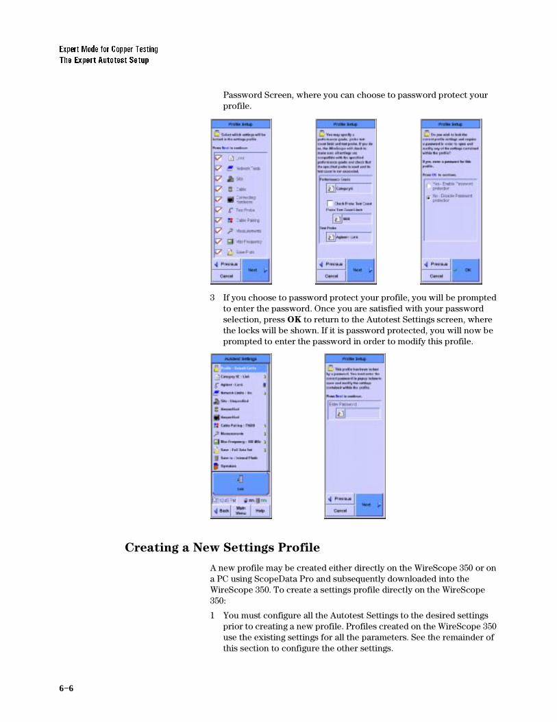
6−6
([SHUW0RGHIRU&RSSHU7HVWLQJ7KH([SHUW$XWRWHVW6HWXS
Password Screen, where you can choose to password protect your profile.
3 If you choose to password protect your profile, you will be prompted to enter the password. Once you are satisfied with your password selection, press OK to return to the Autotest Settings screen, where the locks will be shown. If it is password protected, you will now be prompted to enter the password in order to modify this profile.
Creating a New Settings Profile
A new profile may be created either directly on the WireScope 350 or on a PC using ScopeData Pro and subsequently downloaded into the WireScope 350. To create a settings profile directly on the WireScope 350:
1 You must configure all the Autotest Settings to the desired settings prior to creating a new profile. Profiles created on the WireScope 350 use the existing settings for all the parameters. See the remainder of this section to configure the other settings.

([SHUW0RGHIRU&RSSHU7HVWLQJ7KH([SHUW$XWRWHVW6HWXS
6−7
2 In Expert Mode, press Autotest. On the Autotest Settings screen, press Edit Settings, then press Profile, then press Edit.
3 On the Profile Setup Screen, press Create New Profile, then press Next. Press anywhere in the Profile Name area to open a keyboard to allow you to enter the new profile name. After entering the new name, press OK, then press Next.
4 Change the lock settings by pressing the appropriate boxes. The check marks toggle with subsequent presses. Then press Next. If the Test Probe setting is locked, you will see the center screen below, which will prompt you to select the Performance Grade of the probe as well as the Probe Test Count Limit, if desired. Then press Next. If the Test Probe setting is not locked you will go directly to the

6−8
([SHUW0RGHIRU&RSSHU7HVWLQJ7KH([SHUW$XWRWHVW6HWXS
Password Screen, where you can choose to password protect your profile.
5 If you choose to password protect your profile, you will be prompted to enter the password. Once you are satisfied with your password selection, press OK to return to the Autotest Settings screen, where the locks will be shown. If it is password protected, you will now be prompted to enter the password in order to modify this profile.
Setting the Test Limit
The Expert Mode allows you to set the test limit according to several standards. To set the test limit to a certain standard:
1 In Expert Mode, press Autotest on the Main menu.
2 On the Autotest Setup screen press Edit Settings. On the Autotest Settings screen press the icon second from the top of the list that looks like a page with a number or letter superimposed on it.

([SHUW0RGHIRU&RSSHU7HVWLQJ7KH([SHUW$XWRWHVW6HWXS
6−9
3 Then on the Limit Setup screen, select the desired cabling system performance grade.
1RWH 7KHVFUROOEDURQWKHULJKWRIWKHVFUHHQVKRZVWKHORFDWLRQRIWKHGDWDVKRZQDQGLVQRWDIXQFWLRQDOVFUROOEDU7RVFUROOXVHWKHVFUROOURFNHUDWWKHORZHUULJKWRIWKH:LUH6FRSH
4 Then press Next. The next Limit Setup screen allows you to select Link or Channel test configuration.
Viewing Probe Information
The WireScope can display details about the probes inserted in the tester. If the probes are SmartProbes, the information includes the number of tests the probes have performed.
To view detailed information on the probe currently inserted:
1 In Expert mode, press Autotest on the Main Menu. The Autotest Setup screen displays.

6−10
([SHUW0RGHIRU&RSSHU7HVWLQJ7KH([SHUW$XWRWHVW6HWXS
2 On the Autotest Setup screen, press Edit Settings. The Autotest Settings screen shows a menu of parameters and functions.
3 Press the name of the probe, then press View. The Probe Information screen displays, with information on the probe inserted in the WireScope.
4 If you desire to check the probe test count before each test, press Check Probe Test Count and enter the limit to be tested against.
5 To view information on the probe installed in the DualRemote, press the DualRemote tab. The Probe Information screen displays information about the probe in the DualRemote after running an Autotest.
6 If you desire to check the DualRemote probe test count before each test, press Check Probe Test Count and enter the limit to be tested against.
Setting Network Limits
The WireScope 350 can determine compliance with signal to noise ratio (SNR) requirements for a variety of popular LAN technologies. To do this:
1 In Expert Mode, press Autotest on the Main Menu. The Autotest Settings screen displays.
2 On the Autotest Setup screen press Edit Settings.
3 On the Autotest Settings screen press Network Limits. Then press Edit.
4 On the Networks Setup screen press on the appropriate technology for which you want to certify the tested cabling. A red check will appear in each technology selected. Other includes a variety of legacy network standards.

([SHUW0RGHIRU&RSSHU7HVWLQJ7KH([SHUW$XWRWHVW6HWXS
6−11
Entering the Site Name
The site name identifies the group of settings used on a job, and can be applied to test records for that site.
To enter the site name:
1 On the Autotest Setup screen, press Site, then press Edit. The Site Setup screen displays.
2 Press Create a New Site Name, then press Next. (The OK button changes to a Next button when you select Create a New Site
Name.) The screen changes, to allow naming the site.
1RWH 7RFKDQJHWKHQDPHRUODEHOLQJIRUPDWIRUDQH[LVWLQJVLWHSUHVVWKHVLWHQDPHRQWKHOLVWWKHQSUHVV(GLW9LHZDQG1H[W
3 Press the icon under (QWHU1HZ6LWH1DPH The onscreen keyboard opens.
4 Press the keyboard keys to enter the site name, then press OK. The keyboard closes.

6−12
([SHUW0RGHIRU&RSSHU7HVWLQJ7KH([SHUW$XWRWHVW6HWXS
Choosing the Labeling Format
The labeling format for Expert Mode is the same as that previously described in Chapter 3, Certifying Copper Cabling. See Choosing the
Labeling Format, on page 3-6 for more information.
Choosing the Cable Type
Cable from different manufacturers has different transmission characteristics. The WireScope 350 compensates for those differences if you tell it what cable is used on the job. A grey cable spool icon indicates UTP cabling, a black cable spool icon indicates shielded cabling.
1 On the Autotest Setup screen, press the cable spool icon, then press Edit. The Cable Setup screen displays.
1RWH 7KHVFUROOEDURQWKHULJKWRIWKHVFUHHQVKRZVWKHORFDWLRQRIWKHGDWDVKRZQDQGLVQRWDIXQFWLRQDOVFUROOEDU7RVFUROOXVHWKHVFUROOEXWWRQDWWKHORZHUULJKWRIWKH:LUH6FRSH
2 Select the cable manufacturer, and press Next. The Cable Database screen displays.
3 Select a cable on the list, and press OK. The Autotest Setup screen displays, with the selected cable type next to the cable spool icon. If the cable is not in the cable database, see Adding a new cable
type, on page 3-14.

([SHUW0RGHIRU&RSSHU7HVWLQJ7KH([SHUW$XWRWHVW6HWXS
6−13
Choosing the Connector Type
Connectors from different manufacturers have different transmission characteristics. The WireScope 350 compensates for those differences, if you tell it what connectors are used on the job.
1 On the Autotest Setup screen, press the connector icon, then press Edit. The Connector Setup screen displays.
1RWH 7KHVFUROOEDURQWKHULJKWRIWKHVFUHHQVKRZVWKHORFDWLRQRIWKHGDWDVKRZQDQGLVQRWDIXQFWLRQDOVFUROOEDU7RVFUROOXVHWKHVFUROOEXWWRQDWWKHORZHUULJKWRIWKH:LUH6FRSH
2 Press the manufacturer of the connector, then Next. A list of that manufacturer’s connectors displays.
3 Press the name of the connector, then press OK. The Autotest Setup screen displays, with the selected connector type next to the connector icon. If the connector type is not in the connector database, see Adding a new connector type, on page 3-16.
Choosing the Cable Pairing Convention
To identify the correct pair in the test results, the WireScope must be told what cable pairing convention is used. For example, if the 3,6 pair fails a test, it would be “Pair 2” if using T568A pairing, but it would be “Pair 3” if using T568B pairing.

6−14
([SHUW0RGHIRU&RSSHU7HVWLQJ7KH([SHUW$XWRWHVW6HWXS
1 On the Autotest Setup screen, press Cable Pairing, then press Edit. The Cable Pairing Setup screen displays.
Press the cable pairing convention used on the job, then press OK. The Autotest Setup screen displays, with the cable pairing convention named.
Setting the Measurements
In Expert Mode, you have the ability to specify in detail what measurements are used to determine the certification status of your test. In addition, there are choices for optional features.
1 In Expert Mode, press Autotest on the Main menu.
2 On the Autotest Setup screen press Edit Settings. On the Autotest Settings screen press Measurements. The first Measurements Setup screen identifies the required measurements for the limits you have selected. It is possible to disable the measurements, but it is not recommended. Press Next to view the optional measurements you may want to add to your test. Add them by pressing the name or box.

([SHUW0RGHIRU&RSSHU7HVWLQJ7KH([SHUW$XWRWHVW6HWXS
6−15
3 After you have made your optional choices, press Next to allow you to enable test result analysis functions. It is recommended that you should choose Manufacturer Specific Compensation when you are performing Category 6 channel testing. Press Next when done.
4 The next Measurements Setup screen allows you to choose between Summary ELFEXT data and Complete ELFEXT data storage modes. If you have storage space and/or you will wish to recertify in the future using the stored data, the Complete ELFEXT Mode is recommended. When complete, press Next.
5 The next Measurement Setup Screen allows the user to apply the 3 dB attenuation rule, which provides for special consideration of measurements where the attenuation is less than 3 dB or in certain ISO cases, 4 dB. This rule applies to both NEXT and Return Loss in the ISO case, but only to Return Loss in the TIA case. The WireScope 350 automatically sets this choice based upon the standard chosen previously. It also implements the 4 dB appropriately even though it is called the 3 dB rule. When you are satisfied with the choice, press Next.

6−16
([SHUW0RGHIRU&RSSHU7HVWLQJ7KH([SHUW$XWRWHVW6HWXS
6 The last Measurements Setup screen allows you to skip the automatic fault location calculation. This does not prevent you from using the locator in the Results Details function, but prevents the calculation on each test, including the passing tests. When this selection has been made, press Next to return to the Autotest Settings screen.
Setting the Maximum Frequency
The WireScope 350 allows you to select the maximum range for swept frequency measurements. The choices depend somewhat on the standard selected previously, for example for Category 6, the 100 MHz choice is not available. To set the maximum frequency:
1 In Expert Mode, press Autotest on the Main menu.
2 On the Autotest Setup screen press Edit Settings. On the Autotest Settings screen press Max Frequency. On the Frequency Setup screen select the maximum frequency of the data being stored.
1RWH 7KHUHDVRQWRVHOHFWWKHORZHVWIUHTXHQF\LVWRGHFUHDVHWHVWWLPHDQGGHFUHDVHPHPRU\VWRUDJH7KHDGGLWLRQDORSWLRQDOGDWDLVIRULQIRUPDWLRQRQO\XQOHVV\RXZLVKWRSUHVHUYHWKHGDWDIRUSRVVLEOHODWHUUHFHUWLILFDWLRQDWDKLJKHUIUHTXHQF\VWDQGDUGZLWK6FRSH'DWD3URVRIWZDUHRQD3&,I\RXKDYHQRWVDYHGWKHKLJKHUIUHTXHQF\GDWDWKHUHFHUWLILFDWLRQPD\QRWEHDYDLODEOH)RUH[DPSOHLI\RXWHVWWRWKH&DWHJRU\(&ODVV'VWDQGDUGEXWKDYHOLPLWHG\RXUPD[LPXPIUHTXHQF\WR0+]WKHQ\RXZLOOQRWEHDEOHWRUHFHUWLI\ODWHUZLWKWKHVWRUHGGDWDWR&DWHJRU\&ODVV(ZKLFKUHTXLUHVGDWDWR0+]
Setting the Plot Storage Requirements
Another storage choice is available, whether to save plots or not. Saving plots stores the entire swept frequency measurement. Summary data is the worst case value for each test and is the minimum required for standards compliance. To set the data being stored:
1 In Expert Mode, press Autotest on the Main menu.

([SHUW0RGHIRU&RSSHU7HVWLQJ7KH([SHUW$XWRWHVW6HWXS
6−17
2 On the Autotest Setup screen press Edit Settings. On the Autotest Settings screen press Save, then Edit to bring up the Save Mode Setup screen. Press Summary Data Only or Full Data Set.
1RWH ,I\RXVDYHVXPPDU\GDWDRQO\\RXZLOOQRWEHDEOHWRUHFHUWLI\ODWHUZLWKWKHVDYHGGDWDVLQFHWKHSORWVZLOOQRWEHSDUWRIWKHVWRUHGGDWDXVHGIRUUHFHUWLILFDWLRQE\6FRSH'DWD3UR
Setting the Storage Location
This is the same function as that shown in the System Settings screen. Also when a CompactFlash™ card is inserted, this function will automatically set the storage location to the CompactFlash™ card See Configuring CompactFlash™ Cards, on page 2-6.
Setting the Operator Names
The names of the technicians performing the tests can be entered, and will appear on the test report. This is the same function as that shown in the System Settings section See Entering the Operator Names, on page 3-18. If it has been done already there, it is reflected here.

6−18
([SHUW0RGHIRU&RSSHU7HVWLQJ7KH([SHUW7RROV0HQX
The Expert Tools Menu
The Expert mode Tools menu includes the following:
• Quick Check tests the continuity and length of a cable run. See Running a Quick Check, on page 6-19.
• Certify Networks lets you choose standards for certification of the network. See Certifying a Network, on page 6-20.
• Blink Port blinks the LED on a circuit at an Ethernet hub or switch port. This helps locate the far end of a circuit. See Blinking
the Port, on page 6-21.
• Learn NVP allows the user to determine the NVP (Nominal Velocity of Propagation) of a sample of cable. See Learning the
NVP of a Cable, on page 6-22.
• Measure Length measures the length of each pair of a cable whose type is in the Cable Database. See Measuring the Cable
Length, on page 6-23.
To open the Tools menu:
1 Change to Expert mode (see page 6-3).
2 On the Main Menu, press Tools. The Tools Menu displays.

([SHUW0RGHIRU&RSSHU7HVWLQJ7KH([SHUW7RROV0HQX
6−19
Running a Quick Check
The Quick Check function tests a cable run for shorts, opens, shield integrity, correct termination, and length.
To run a Quick Check:
1 On the Tools menu (see page 6-18), press Quick Check. The test runs, and a Pass or Fail screen displays.
Viewing Details of Quick Check Results
The WireScope can display detailed information about both passing and failing results of a Quick Check.
To view results details:
1 On the Quick Check PASS or FAIL screen, press Details. The Wiremap Data screen displays.
2 The results may be saved, if desired.
OR

6−20
([SHUW0RGHIRU&RSSHU7HVWLQJ7KH([SHUW7RROV0HQX
Certifying a Network
The Expert mode Tools menu includes Certify Network, which lets you test a cable for conformance to different network standards.
To certify a network:
1 Connect the WireScope and DualRemote to the cable.
2 On the Expert mode Tools Menu (see page 6-18), press Certify
Network. The Certify Networks Setup screen displays.
3 Press a standard in the list to select it. A checkmark appears next to each selected standard.
4 To test the network to the selected standards, press Start Test. The test executes, and WireScope displays a Pass or Fail screen.
You can save and view details of the test results as with any test by pressing Details. See Saving Test Results, on page 5-3, and Viewing
Result Details, on page 5-5.

([SHUW0RGHIRU&RSSHU7HVWLQJ7KH([SHUW7RROV0HQX
6−21
Blinking the Port
To locate the switch or hub a cable is connected to, the WireScope 350 can blink the switch or hub port. The technician using the WireScope at the wall plate end of the circuit blinks the indicator on the panel at the hub or switch end.
To blink the port:
1 On the Tools menu (see page 6-18), press Blink Port. The Blink Port screen displays.
2 Press Start. The port begins blinking, and the Start button changes to a Stop button.
3 To stop the blinking, press Stop. The blinking stops.

6−22
([SHUW0RGHIRU&RSSHU7HVWLQJ7KH([SHUW7RROV0HQX
Learning the NVP of a Cable
The WireScope can determine the NVP (Nominal Velocity of Propagation) of a cable, for use in certification testing. NVP is expressed as a percentage of the speed of light. you must use a sample of the cable at least 50 feet (15 meters) long. Longer cable samples produce more accurate results.
To learn the NVP:
1 Measure the length of a sample of the cable.
2 Connect the cable sample to the WireScope. Do not connect the DualRemote.
3 On the Expert mode Tools menu (see page 6-18), press Learn NVP. The Learn NVP screen displays.
4 Press the Cable Length field. The numeric keyboard opens.
5 Press the backspace arrow to erase any value in the number field, then enter the length of the cable sample, in or meters. Press OK. The
72

([SHUW0RGHIRU&RSSHU7HVWLQJ7KH([SHUW7RROV0HQX
6−23
keyboard closes, and the Learn NVP screen displays new number in the Cable Length field.
6 Press Calculate. The WireScope calculates the NVP of the sample cable, and displays it in the NVP field.
Measuring the Cable Length
The WireScope 350 can measure the length of an attached cable if the cable type is in its database.
To measure the length of a cable:
1 Connect the WireScope to the cable. Do not attach the DualRemote.
2 On the Tools menu, press Measure Length. The Measure Length screen displays.

6−24
([SHUW0RGHIRU&RSSHU7HVWLQJ7KH([SHUW7RROV0HQX
3 Press Select. The Cable Setup screen displays.
4 Select the cable manufacturer, and press Next. The Cable Database screen displays.
1RWH 7KHUHDVRQWRVHOHFWWKHFDEOHW\SHLVWKDWLQRUGHUIRUWKH:LUH6FRSHWRDFFXUDWHO\PHDVXUHOHQJWKLWQHHGVWKHSURSHU193YDOXHVWRUHGZLWKWKHFDEOHVSHFLILFDWLRQV
5 Select a cable on the list, and press OK. The Measure Length screen displays, with the selected cable type shown.
6 Press Measure. The WireScope calculates the length of the cable, and displays the length of each twisted pair on the Measure Length screen.

([SHUW0RGHIRU&RSSHU7HVWLQJ5XQQLQJ&2$;DQG7:,1$;$XWRWHVWV
6−25
Running COAX and TWINAX Autotests
The WireScope 350 and the DualRemote 350 support both Coaxial and Twinaxial standards. This section will instruct you how to test to these standards.
COAX Testing
Coaxial cable (also called Coax) consists of an insulated central conducting wire wrapped in another cylindrical conducting wire. Both of these wires are encased in an insulating layer and an outer protective layer. Coax is typically used in carrying high-speed data and in CATV.
Testing of coaxial cable checks only for length and cable integrity. Because of this, there is no need to calibrate before the Autotest. Only a subset of the tester settings applies to Coax testing. These settings are shown on the screens below.
1 Insert the Coax probe in the WireScope 350’s SmartProbe port and connect it to the coaxial cable to be tested. The WireScope 350 will automatically detect it and change several settings. There is no need to use the DualRemote 350 in certifying Coax cables. Press the Autotest button on the Main Menu to bring up the Autotest Setup screen. Press the Edit Settings button to change any settings.
1RWH ,WPD\EHQHFHVVDU\IRU\RXWRDGGDQHZGHVFULSWLRQWRWKHFDEOHGDWDEDVHDGGQDPHVSHFLI\SDLUIRUFDEOHSDLUFRXQWWKHQVHOHFW&RD[WKHQHLWKHUVSHFLI\WKHFDEOH·V193RUVHOHFW&DOFXODWH193IURPOHQJWKILQDOO\DGGRUVHOHFWWKHWDUJHWSHUIRUPDQFHJUDGHIRUWKHFDEOHLIDSSOLFDEOHRWKHUZLVH8QVSHFLILHG
2 When the Coax probe is inserted a default Coax cable is automatically selected. You can change to a different Coax cable in the Autotest Settings screen.
3 The WireScope 350 is capable of certifying 10Base-2 and 10Base-5 network operation over Coax. By selecting Other in the Network Limits of the Autotest Settings screen, or in the Summary screen of

6−26
([SHUW0RGHIRU&RSSHU7HVWLQJ5XQQLQJ&2$;DQG7:,1$;$XWRWHVWV
the Certify Networks screen, you can enable the certification of these networks.
4 Press the Start Test button from the Autotest Setup screen to perform the Coax Autotest (or Certify Network test).
Results
The Coax Autotest evaluates length and cable integrity. These results are shown in both the diagram at the top of the screen and the table at the bottom. Delay and NVP information are also shown. The results of coax network certification are also shown in the bottom section of the result screen. Press the Details button to display the Wiremap Data screen containing additional information about the test.
Twinax Testing
Twinaxial (also called Twinax) cables are able to carry high frequencies and are most often used for data transmissions and video applications. Twinax consists of one twisted pair and a metallic shield.
Testing of Twinaxial cable checks only for length and cable integrity. Because of this, there is no need to calibrate before the Autotest. Only a subset of the tester settings applies to Twinax testing. These settings are shown on the screens below.
1 Insert the Twinax probe in the WireScope 350’s SmartProbe port and connect it to the Twinax cable to be tested. Press the Autotest
button on the Main Menu to bring up the Autotest Setup screen shown above. When the Twinax probe is inserted a default Twinax

([SHUW0RGHIRU&RSSHU7HVWLQJ5XQQLQJ&2$;DQG7:,1$;$XWRWHVWV
6−27
cable is automatically selected. Press the Edit Settings button to change any settings.
1RWH 7KH:LUH6FRSHGRHVQRWVSHFLI\DQ\QHWZRUNLQJVWDQGDUGVWKDWUXQRQ7ZLQD[FDEOH$Q\DWWHPSWWRUXQD&HUWLI\1HWZRUNVWHVWRQD7ZLQD[FDEOHZLOOWULJJHUDQHUURUPHVVDJHVWDWLQJWKDWQRQHRIWKHQHWZRUNVVHOHFWHGDUHFRQILJXUHGWRUXQRQWKLVW\SHRIFDEOH
2 Press the Start Test button from the Autotest Setup screen to perform the Twinax Autotest
Results
The Twinax Autotest evaluates length and cable integrity. Twinax cable integrity includes the detection of a properly connected shield. These results are shown in both the diagram at the top of the screen and the table at the bottom. Delay and NVP information are also shown. Pressing the Details button shows more information about the test.

6−28
([SHUW0RGHIRU&RSSHU7HVWLQJ5XQQLQJ&2$;DQG7:,1$;$XWRWHVWV

7−1Agilent Technologies
7Expert Mode for Fiber Testing
About Fiber Expert Mode 7-2
Changing to Expert Mode 7-2
Viewing Probe Information 7-3
The Fiber Tools Menu 7-5
Using the Loss Meter 7-5
Measuring Length and Delay 7-6
Using the Power Meter 7-6
Using Trace Mode 7-7
Learning the NVP of a Fiber 7-7

7−2
([SHUW0RGHIRU)LEHU7HVWLQJ$ERXW)LEHU([SHUW0RGH
About Fiber Expert Mode
WireScope’s Expert Mode includes many configuration and testing options not included in the standard test configurations.
Changing to Expert Mode
To change the WireScope tester from standard configuration to Expert Mode:
1 On the Fiber Main menu, press System. The System Settings screen displays.
2 On the System Settings screen, press User Interface, then press Edit. The User Interface Setup screen displays.
On the User Interface Setup screen, press Expert Mode to turn it on, then press OK. The System Settings screen displays.

([SHUW0RGHIRU)LEHU7HVWLQJ9LHZLQJ3UREH,QIRUPDWLRQ
7−3
Viewing Probe Information
The WireScope can display details about the probes installed in the tester.
To view detailed information on the installed probes:
1 In Expert mode, press Fiber Autotest on the Main Menu. The Fiber Autotest Setup screen displays.
2 On the Fiber Autotest Setup screen, press Edit Settings. The Fiber Autotest Settings screen displays.

7−4
([SHUW0RGHIRU)LEHU7HVWLQJ9LHZLQJ3UREH,QIRUPDWLRQ
3 Press the name of the probe, then View. The Probe Information screen displays, with information on the probe installed in the WireScope.
4 To view information on the probe installed in the DualRemote, press the DualRemote tab. The Probe Information screen displays information about the probe in the DualRemote.
.

([SHUW0RGHIRU)LEHU7HVWLQJ7KH)LEHU7RROV0HQX
7−5
The Fiber Tools Menu
The Expert mode Fiber Tools menu contains the following:
• Loss Meter This tool continuously measures and reports the loss on connected fiber cables.
• Length & Delay This tool measures the length and propagation delay of connected fiber cables.
• Power Meter This tool measures the power level reaching the Fiber SmartProbe from a light source connected to the fiber cable.
• Trace Mode This activates the transmitter on the Fiber SmartProbe, to verify that light reaches the other end of a connected cable.
• Learn Fiber NVP This tool teaches the WireScope the NVP of a cable sample.
To open the Fiber Tools menu:
1 Change to Expert mode. (See Changing to Expert Mode, on page 7-2.)
2 On the Expert Mode Main Menu, press Fiber Tools. The Fiber Tools screen displays.
Using the Loss Meter
To use the Loss Meter:
1 On the Fiber Tools menu, press Loss Meter. The Fiber Loss Meter screen displays.
2 To clear the values in the data table at the center of the screen, press Clear Peak.
3 To write the current data table to the results database, press Save.
4 To select the test configuration or to specify the fiber type, press Quick Setup.
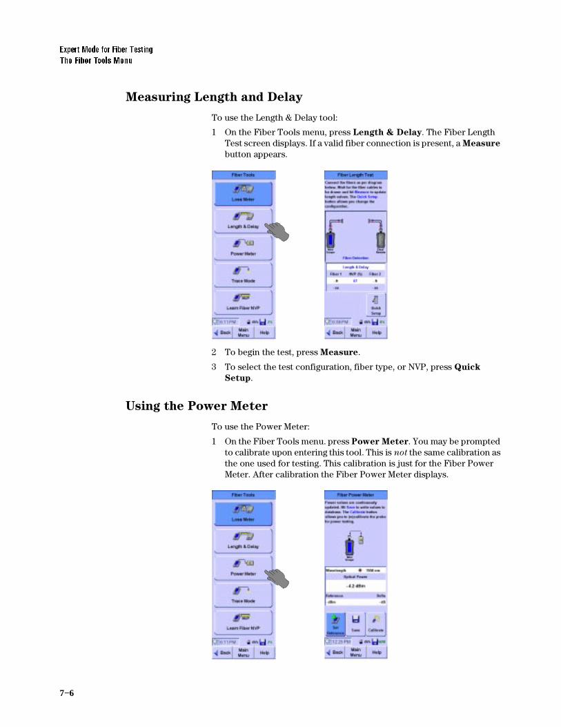
7−6
([SHUW0RGHIRU)LEHU7HVWLQJ7KH)LEHU7RROV0HQX
Measuring Length and Delay
To use the Length & Delay tool:
1 On the Fiber Tools menu, press Length & Delay. The Fiber Length Test screen displays. If a valid fiber connection is present, a Measure button appears.
2 To begin the test, press Measure.
3 To select the test configuration, fiber type, or NVP, press Quick
Setup.
Using the Power Meter
To use the Power Meter:
1 On the Fiber Tools menu. press Power Meter. You may be prompted to calibrate upon entering this tool. This is not the same calibration as the one used for testing. This calibration is just for the Fiber Power Meter. After calibration the Fiber Power Meter displays.

([SHUW0RGHIRU)LEHU7HVWLQJ7KH)LEHU7RROV0HQX
7−7
2 To set the current power value as a reference, press Set Reference. The difference is shown in the Delta field. The actual measurement is shown in the Optical Power field.
3 To write the current data table to the results database, press Save.
4 To calibrate the Power Meter, press Calibrate.
Using Trace Mode
To turn on the Fiber SmartProbe’s transmitter:
• On the Fiber Tools menu, press Trace Mode. The FIber Trace Mode screen displays and indicates that the transmitter is active.
Learning the NVP of a Fiber
To learn the NVP of a fiber cable sample:
1 Connect a known length sample of the fiber to the Fiber SmartProbe. The sample must be at least 50 feet (15 meters) long.
2 On the Fiber Tools menu, press Learn Fiber NVP. The Learn Fiber NVP screen displays. Use the Quick Setup to help configure the cable for single ended or double ended test configuration and to provide fiber construction details prior to the test. You may need to calibrate using the test jumper depending on which test configuration you

7−8
([SHUW0RGHIRU)LEHU7HVWLQJ7KH)LEHU7RROV0HQX
choose. If you need to calibrate, use the Calibration tool on the Main Menu.
3 Press the Fiber Length field. The numeric keyboard opens.
4 Enter the length of the sample fiber, and press OK to close the keyboard. Make sure to use the correct length units (feet or meters.)
• When measuring two fibers, enter the average length of the two.
• When measuring one length of fiber looped back to the WireScope, enter the entire length of the fiber.
5 Press Measure to learn the NVP of the fiber sample. The NVP displays in the NVP (%) field of the Learn Fiber NVP screen.

8−1Agilent Technologies
8Reference
Measurements 8-2
Wiremap 8-2
Length 8-2
Propagation Delay and Skew 8-2
Near-end Crosstalk (NEXT) 8-3
Attenuation 8-3
Return Loss 8-4
Equal Level Far-End Crosstalk (ELFEXT) 8-4
Attenuation-to-Crosstalk Ratio (ACR) 8-4
Power Sum NEXT (PSNEXT) 8-4
Power Sum ELFEXT (PSELEXT) 8-5
Power Sum ACR (PSACR) 8-5
Resistance 8-5
Ambient Noise 8-5
Calibration 8-6
Measurement Calibration 8-6
Touch-Screen Calibration 8-7
Memory Requirements 8-8

8−2
5HIHUHQFH0HDVXUHPHQWV
Measurements
The WireScope 350 makes the following test measurements.
Wiremap
Wiremap testing checks for proper continuity and termination of cables. The test identifies the following faults:
• Short circuit
• Open circuit
• Reversed pairs
• Transposed pairs
• Split pairs
• Shield continuity faults
Length
Length measurements determine the electrical length of cable runs up to 1100 feet (335 meters). Accurate length measurements require accurate NVP settings. Choosing a cable type from the WireScope’s database automatically loads NVP settings, or the NVP for a cable can be measured on a sample (see Learning the NVP of a Cable, on page 6-22).
/HQJWK0HDVXUHPHQW6SHFLILFDWLRQV
Propagation Delay and Skew
The Propagation Delay test measures the one-way propagation delay over each pair of the tested cable run. Skew is the difference in propagation delay between the pairs with the longest and shortest delay in a cable.
3URSDJDWLRQ'HOD\DQG6NHZ0HDVXUHPHQW6SHFLILFDWLRQV
$FFXUDF\ ±RU±IHHW0ZKLFKHYHULVJUHDWHU
5HVROXWLRQ ±IRRW00
0LQLPXP'LVWDQFH IHHW0
0D[LPXP'LVWDQFH IHHW0
$FFXUDF\ ±RU±QDQRVHFRQGVZKLFKHYHULVJUHDWHU
5HVROXWLRQ ±QDQRVHFRQGV
0LQLPXP'HOD\ QDQRVHFRQGV
0D[LPXP'HOD\ QDQRVHFRQGV

5HIHUHQFH0HDVXUHPHQWV
8−3
Near-end Crosstalk (NEXT)
NEXT measures near-end coupling between pairs in the tested cable run, at both ends of a cable, over 6 pair combinations.
1(;70HDVXUHPHQW6SHFLILFDWLRQV
Attenuation
Attenuation measures the decrease in signal strength over the length of all pairs in a cable.
$WWHQXDWLRQ0HDVXUHPHQW6SHFLILFDWLRQV
'HOD\6NHZ 7KHGLIIHUHQFHLQQDQRVHFRQGVEHWZHHQWKHORQJHVWDQGVKRUWHVWPHDVXUHGSURSDJDWLRQGHOD\DPRQJWKHIRXUSDLUVRIDVLQJOHFDEOHUXQ
)UHTXHQF\5DQJH ²0+]
)UHTXHQF\6WHS6L]HV N+]N+]N+]0+]VHWDXWRPDWLFDOO\EDVHGRQVHOHFWHGVWDQGDUGV
5HVROXWLRQ G%
'\QDPLF5DQJH G%RUG%EH\RQG&DWHJRU\EDVLFOLQNOLPLWZKLFKHYHULVKLJKHU
%DVHOLQH$FFXUDF\ EHWWHUWKDQ7,$/HYHO,,,UHTXLUHPHQW
TIA level III measurement parameter and tester accuracy requirements per TIA Category 6 Draft – Addendum to TIA-568-B and ISO/IEC 61935-1 draft amendment 1, 10/99
)UHTXHQF\5DQJH ²0+]
)UHTXHQF\6WHS6L]H N+]N+]N+]0+]VHWDXWRPDWLFDOO\EDVHGRQVHOHFWHGVWDQGDUGV
5HVROXWLRQ G%
'\QDPLF5DQJH G%
%DVHOLQH$FFXUDF\ EHWWHUWKDQ7,$/HYHO,,,UHTXLUHPHQW
TIA level III measurement parameter and tester accuracy requirements per TIA Category 6 Draft – Addendum to TIA-568-B and ISO/IEC 61935-1 draft amendment 1, 10/99

8−4
5HIHUHQFH0HDVXUHPHQWV
Return Loss
Return Loss measures the degradation of signal over all four pairs from each end of the tested cable run.
5HWXUQ/RVV0HDVXUHPHQW6SHFLILFDWLRQV
Equal Level Far-End Crosstalk (ELFEXT)
ELFEXT measures far-end coupling between pairs in the tested cable, for all pair combinations.
(/)(;70HDVXUHPHQW6SHFLILFDWLRQV
Attenuation-to-Crosstalk Ratio (ACR)
The ratio of the measured attenuation and the near-end crosstalk (NEXT) at each frequency point.
Power Sum NEXT (PSNEXT)
Computed for each pair by calculating a power sum total of the pair-to-pair NEXT from the three other pairs.
)UHTXHQF\5DQJH ²0+]
)UHTXHQF\6WHS6L]H N+]N+]N+]0+]VHWDXWRPDWLFDOO\EDVHGRQVHOHFWHGVWDQGDUGV
5HVROXWLRQ G%
'\QDPLF5DQJH G%
%DVHOLQH$FFXUDF\ EHWWHUWKDQ7,$/HYHO,,,UHTXLUHPHQW
TIA level III measurement parameter and tester accuracy requirements per TIA Category 6 Draft – Addendum to TIA-568-B and ISO/IEC 61935-1 draft amendment 1, 10/99
)UHTXHQF\5DQJH ²0+]
)UHTXHQF\6WHS6L]H N+]N+]N+]0+]VHWDXWRPDWLFDOO\EDVHGRQVHOHFWHGVWDQGDUGV
5HVROXWLRQ G%
'\QDPLF5DQJH G%RUG%EH\RQG&DWHJRU\OLQNOLPLWZKLFKHYHULVKLJKHU
%DVHOLQH$FFXUDF\ EHWWHUWKDQ7,$/HYHO,,,UHTXLUHPHQW
TIA level III measurement parameter and tester accuracy requirements per TIA Category 6 Draft – Addendum to TIA-568-B and ISO/IEC 61935-1 draft amendment 1, 10/99
.

5HIHUHQFH0HDVXUHPHQWV
8−5
Power Sum ELFEXT (PSELEXT)
Computed for each pair by calculating a power sum total of the pair-to-pair ELFEXT from the three other pairs.
Power Sum ACR (PSACR)
The ratio of the measured attenuation and the computed power sum near-end crosstalk (PSNEXT) at each frequency point.
Resistance
The DC loop resistance for each pair in the tested cable run.
5HVLVWDQFH0HDVXUHPHQW6SHFLILFDWLRQV
Ambient Noise
The ambient noise spectrum of each pair immediately after the autotest.
$PELHQW1RLVH0HDVXUHPHQW6SHFLILFDWLRQV
5DQJH ²Ω
$FFXUDF\ ±
)UHTXHQF\5DQJH ²0+]
6HQVLWLYLW\ P9506
$FFXUDF\ ±

8−6
5HIHUHQFH&DOLEUDWLRQ
Calibration
Measurement Calibration
Remote Calibration
Remote calibration establishes a common zero reference for the WireScope 350 and its associated DualRemote 350, before any end-to-end measurements are taken.
You must perform a remote calibration if you use your WireScope 350 with a different DualRemote 350, or if you upgrade the software in either the WireScope or DualRemote. The WireScope stores the serial number information of the DualRemote that it has been calibrated with. Before each measurement, the WireScope checks the serial numbers of the DualRemote to which it is connected. If the WireScope does not have remote calibration data stored for the detected DualRemote, a warning appears, asking you to calibrate the DualRemote.
Agilent Technologies recommends running the remote calibration once a day, at the beginning of a testing session.
Environmental Calibration (Internal)
Environmental calibration compensates for the effects of ambient temperature and voltage variations. The WireScope 350 and DualRemote 350 use internal calibration paths to connect the signal source and measurement circuits, establishing a local calibration reference before each measurement. No operator involvement is required.
Field Verification of Baseline Accuracy
The Self-Test probe (part # N2594A-015) can be used in the field to verify the baseline accuracy of a WireScope 350 or DualRemote 350. The Self-Test probe uses the SmartProbe port interface to automate the required setups for this function.
To run a Self Test on the WireScope 350:
1 Make sure that the WireScope 350 display displays the main menu.
2 Insert the Self-Test probe in the SmartProbe port
3 Press the OK key. A PASS or FAIL screen displays.
The PASS screen indicates that the WireScope’s baseline calibration data is valid.
If a FAIL screen displays, contact Agilent Technical Support (see Technical Support, on page 1-21).

5HIHUHQFH&DOLEUDWLRQ
8−7
To run a self test on the DualRemote 350:
1 Insert the Self-Test probe in the SmartProbe port of the DualRemote 350.
2 Press the OK key. The Pass/Fail LED on the front panel of the DualRemote 350 indicates the outcome of the self test.
If the self test fails, the DualRemote 350 requires a new baseline calibration or repair. Contact Agilent Technical Support (see Technical
Support, on page 1-21).
Touch-Screen Calibration
If it seems that the WireScope 350 is not responding correctly to taps on the touch screen, you may need to calibrate the touch screen to bring it into alignment with the underlying display.
To calibrate the touch screen:
1 Ensure that you have the stylus available.
2 On the Main Menu, press System. The System Settings screen displays.
3 On the System Settings screen, press Calibrate Touch Screen, then press Edit. A Calibration screen displays.
4 Using the stylus, press the screen where the onscreen instructions direct.
When the calibration is complete, the System Settings screen displays.

8−8
5HIHUHQFH0HPRU\5HTXLUHPHQWV
Memory Requirements
The amount of memory that each test result takes up depends on the options that you set before starting the test. Generally, if you save plots with each test, test result files are larger than if you omit plots. When you save plots, the size of the result file depends on the maximum frequency selected, and on how many additional measurements each autotest includes.
The WireScope 350 allocates approximately 4MB of internal Flash memory for test result storage. The exact amount of memory available depends on the size of the WireScope 350 software.
The following table lists approximate record storage capacities for the internal Flash memory when configured for 4MB and for a 32 MB removable CompactFlash™ card and for comparison, a 192 MB card. All sizes of CompactFlash™ will work as extra storage.
6DYHG7HVW&DSDFLWLHV
$XWRWHVW7\SH &RQILJXUDWLRQ
6WRUHG1(;7)UHTXHQF\3RLQWV
&DSDFLW\RI5HFRUGV
,QWHUQDO0%)ODVK
0%&)ODVK&DUG
0%&)ODVK&DUG
&DWHJRU\(RUZLWKRXWSORWV
1RQH
&DWHJRU\(RUZLWKRXWSORWV
$PELHQWQRLVHVZHHSRQDQGQHWZRUNWHVWV
&DWHJRU\(ZLWKSORWVVDYHG
3ORWVWR0+]
&DWHJRU\ZLWKSORWVVDYHG
3ORWVWR0+]
&DWHJRU\ZLWKSORWVVDYHG
3ORWVWR0+]$PELHQWQRLVHVSHFWUXP1HWZRUNV$OO2SWLRQV21

9−1Agilent Technologies
9Specifications
Physical 9-2
Environmental 9-2
Electrical 9-3
Ports 9-4
Display 9-5
Fiber SmartProbe+ -6

9−2
6SHFLILFDWLRQV3K\VLFDO
Physical
The WireScope and DualRemote are the same size, and weigh the same.
Environmental
Note: If this equipment is used in a manner not specified by themanufacturer, the protection provided by the equipmentmay be impaired and successful operation can not be guaranteed.
6L]H µ[µ[µ+:'[[FP
:HLJKW OEVNJ
,QGRRU2XWGRRU ,QWHQGHGIRULQGRRUXVHQRWZHDWKHUL]HG
2SHUDWLQJWHPSHUDWXUHUDQJH
WR° &WR°)
6WRUDJHWHPSHUDWXUHUDQJH ² WR 55° &WR°)
0D[LPXPKXPLGLW\ IRUWHPSHUDWXUHVWR° &°)
$OWLWXGH 7RPHWHUV
3ROOXWLRQGHJUHH

6SHFLILFDWLRQV(OHFWULFDO
9−3
Electrical
&DXWLRQ 8VHRQO\WKHDFDGDSWHUVXSSOLHGLQWKH:LUH6FRSH.LW8VLQJRWKHUSRZHUDGDSWHUVPD\GDPDJHWKHWHVWHUDQGZLOOYRLGLWVZDUUDQW\
1RWH 7KLVGHYLFHFRPSOLHVZLWKSDUWRIWKH)&&5XOHV2SHUDWLRQLVVXEMHFWWRWKHIROORZLQJWZRFRQGLWLRQV7KLVGHYLFHPD\QRWFDXVHKDUPIXOLQWHUIHUHQFHDQGWKLVGHYLFHPXVWDFFHSWDQ\LQWHUIHUHQFHUHFHLYHGLQFOXGLQJLQWHUIHUHQFHWKDWPD\FDXVHXQGHVLUHGRSHUDWLRQ
%DWWHU\ $UHPRYDEOHUHFKDUJHDEOH1LFNHO0HWDO+\GULGH1L0+EDWWHU\SDFNW\SLFDOO\SURYLGHVKRXUVRIRSHUDWLRQEHWZHHQFKDUJHVGHSHQGLQJRQXVHDQGSRZHUPDQDJHPHQWVHWWLQJV$QLQWHUQDOIDVWFKDUJHUUHFKDUJHVWKH1L0+EDWWHU\SDFNLQOHVVWKDQKRXUV([WUDEDWWHU\SDFNVDUHDYDLODEOH%DWWHU\SDFNVSHFLILFDWLRQ3DUW1XPEHU1$ 9GFP$K
([WHUQDOSRZHU 3RZHUFRQYHUWHU([WHUQDODFWRGFSRZHUFRQYHUWHU3DUW1XPEHU1$IRU9$&PRGHOV3DUW1XPEHU1$IRU9$&PRGHOVVXSSOLHV 9GF $WRWKH:LUH6FRSHRU'XDO5HPRWHSRZHUFRQQHFWRU3RZHUFRQQHFWRUSRODULW\3RVLWLYHRQWKHRXWHUVOHHYH1HJDWLYHRQWKHWLS
0DLQVVXSSO\YROWDJH 0XVWEHZLWKLQRIQRPLQDOYROWDJH
,QVWDOODWLRQRYHUYROWDJH &DWHJRU\,,

9−4
6SHFLILFDWLRQV3RUWV
Ports
SmartProbe test port
Attachment point for test probes. Interface contains high performance signal channels for measurement functions and two-way control interface for reading and controlling active test probes.
Serial port
Allows the WireScope 350 or DualRemote 350 to connect to PCs or printers. Connector is an 8-pin micro-DIN. Pin out:
USB-A port
WireScope 350 only. The USB-A port allows the WireScope 350 to connect to USB peripherals. Provides up to 100 mA @ 5 Vdc for attached USB peripherals.
USB-B port
WireScope 350 and DualRemote 350. The USB-B port allows the WireScope 350 or DualRemote 350 to connect to a PC equipped with a USB port.
Talkset connector (3.6 mm phone jack)
WireScope 350 and DualRemote 350. Supports two way voice communication between WireScope DualRemote operators over cable run under test. Accepts Agilent talkset (Part Number N2605A-137).
CompactFlash™ card slot
Provides removable non-volatile storage for test result files. Supports any standard CompactFlash™ Flash storage card. Densities as high as 512MB are presently available. Data stored in standard format compatible with PCMCIA-ATA specification.
'LQSLQ 6LJQDO '%SLQ '%SLQ
'75
5;'
*1'
12786('
7;'
12786('
.

6SHFLILFDWLRQV'LVSOD\
9−5
Display
6.625” (16.83 cm) diagonal backlit color LCD. Resolution: 240 (H) x 640 (V). The display is capable of displaying text and graphics in up to 256 colors.

9−6
6SHFLILFDWLRQV)LEHU6PDUW3UREH
Fiber SmartProbe+
General FiberSmartProbe+850nm, Fiber SmartProbe+ 1300nm Fiber SmartProbe+ 1310nm, Fiber SmartProbe+ 1550nm
Size 2.4” x 1.6” x 0.8”(6.0 cm x 4.0 cm x 2.5 cm)
2.4” x 1.6” x 0.8”(6.0 cm x 4.0 cm x 2.5 cm)
Optical Connectors ST® x 2 SC x 2Power Source Draws power from WireScope 155 or
DualRemote 155 via intelligent test port interfaceDraws power from WireScope 155 orDualRemote 155 via intelligent test port interface
Operating Temperature 0o to 40 o C 0o to 40 o CStorage Temperature - 10o to 55 o C - 10o to 55 o COperating Humidity 10 to 90% non-condensing 10 to 90% non-condensingMaximum Relative Humidity 80% for temperatures up to 31 C, decreasing
linearly to 50% relative humidity at 40 C80% for temperatures up to 31 C, decreasinglinearly to 50% relative humidity at 40 C
Altitude Up to 2000 meters Up to 2000 meters
Detector FiberSmartProbe+850nm, Fiber SmartProbe+ 1300nm Fiber SmartProbe+ 1310nm, Fiber SmartProbe+ 1550nm
Receive Wavelengths 850 and 1300nm 1310nm and 1550nmMeasurement Accuracy +/-0.2dB @ -20dBm +/-0.2dB @ -20dBmDynamic Range 0 to –40 dBm 0 to –40 dBmDetector Type Germanium Germanium
Transmitter FiberSmartProbe+850nm, Fiber SmartProbe+ 1300nm Fiber SmartProbe+ 1310nm, Fiber SmartProbe+ 1550nm
Power Output (into 62.5/125 multimode fiber)-10dBm (850nm), -15dBm (1300nm)
(into 9/125 singlemode fiber)-3 dBm (1310nm and 1550nm)
Source Type LED Stabilized Class 1 LASER2 product in accordancewith EN 60825.1 and FDA 21 CFR 1040.10.
Center Wavelength 1310nm +/- 30nm, 1550nm +/- 30nmSpectral Bandwidth (RMS) < 5nmStability N/A +/- 0.1dB, 1Hr. @ 25 CStabilization Time N/A < 5 min.
Cable Length FiberSmartProbe+850nm, Fiber SmartProbe+ 1300nm Fiber SmartProbe+ 1310nm, Fiber SmartProbe+ 1550nm
Accuracy (whichever is greater) +/- 4% or +/- 1.5 meters +/- 4% or +/- 1.5 metersResolution +/- 1.5 meters +/- 1.5 metersDistance1 Range 0 – 4 km for 3.75 dB/km @ 850nm
0 – 10 km for 1.50 dB/km @ 1300nm0 – 50 km for 0.5dB/km @ 1310nm and 1550nm
Propagation Delay FiberSmartProbe+850nm, Fiber SmartProbe+ 1300nm Fiber SmartProbe+ 1310nm, Fiber SmartProbe+ 1550nm
Accuracy (whichever is greater) +/- 4% or +/- 6 nanoseconds +/- 4% or +/- 6 nanosecondsResolution +/- 6 nanoseconds +/- 6 nanosecondsRange 0 – 300 microseconds 0 – 300 microseconds
1 Assumes double-ended configuration with –15dB maximum multimodelink loss and 25dB maximum singlemode link loss. Divide by two forsingle-ended configuration.
2 For safety the transmitter should never be viewed directly with the naked eye, a lens, ormagnifying device.
KLASSE 1 LASER PRODUKT
• ST is a registered trademark of AT&T

5988-7138EN index - 1
Index
Aac adapter
specifications, 9-3using, 2-2
accessories, 1-6ACR measurement, 8-4ambient noise measurement, 8-5attenuation measurement, 8-3
Bbattery
capacity, 2-2indicator on DualRemote, 1-18removing, 2-2safety, 2-3
blinking hub port, 6-21
CCable Pairing, 6-13cabling, connecting, 2-4calibration
for copper tests, 3-2for fiber test, method A, 4-4for fiber test, method B, 4-5for fiber test, method C, 4-6touch screen, 8-7
certifyingnetwork, 6-20
channel test, 1-11charging port, 1-3CompactFlash card
configuring, 2-6icon, 1-14installing, 2-6slot, 1-5
connecting to cabling, 2-4copper tools menu, 6-18
DData entry options, 1-14
keyboard, 1-14keypad, 1-14
detailed test results, viewing, 5-5
EELFEXT measurement, 8-4Environmental Calibration, 8-6expert mode
copper, 6-3fiber, 7-2
Ffaults, locating, 5-7, 5-9fiber length and delay, 7-6fiber loss meter, 7-5fiber NVP, learning, 7-7fiber power meter, 7-6fiber tools menu, 7-5fiber trace mode, 7-7field verification, 8-6
Hhelp
online, 1-15telephone, 1-21
hub port, blinking, 6-21
Iinterface, user, 1-13
Kkeyboard
telephone-style, 1-14typewriter-style, 1-14
LLabeling, 6-12learning copper NVP, 6-22length measurement, 8-2link test, 1-11locating faults, 5-7, 5-9Lock, 6-5loss meter, fiber, 7-5
Mmeasurements, 8-2
ACR, 8-4ambient noise, 8-5attenuation, 8-3ELFEXT, 8-4length, 8-2NEXT, 8-3power sum ACR, 8-5propagation delay, 8-2PSELEXT, 8-5PSNEXT, 8-4resistance, 8-5return loss, 8-4wiremap, 8-2
NNetwork Limits, 6-10network, certifying, 6-20NEXT measurement, 8-3NVP
learning copper, 6-22learning fiber, 7-7
Oonline Help, 1-15
Ppass/fail
indicator on DualRemote, 1-19phone for support, 1-21plots, viewing, 5-6power meter, fiber, 7-6power sum ACR measurement, 8-5probe data, viewing, 2-4probes, 2-4profile, 6-4, 6-6propagation delay measurement, 8-2PSELEXT measurement, 8-5PSNEXT measurement, 8-4
RRecommended service interval
DualRemote 350, 8-6remote calibration, 8-6requirements, system, 1-4resistance measurement, 8-5return loss measurement, 8-4
SSaving plots, 6-16saving test results, 5-3self test probe, 8-6serial port, 1-3Site Name, 6-11SmartProbe test port, 1-3SmartProbes, 2-4software upgrade, 1-20support, 1-21system requirements, 1-4
Ttalkset jack, 1-3tech support, 1-21telephone-style keyboard, 1-14

5988-7138EN index - 2
Test Limit, 6-8test results
interpreting, 5-7saving, 5-3
testschannel, 1-11link, 1-11
tools menucopper, 6-18fiber, 7-5
touch screen calibration, 8-7trace mode, fiber, 7-7typewriter-style keyboard, 1-14
Uupgrade, software, 1-20USB ports, 1-3user interface, 1-13
Vviewing plots, 5-6
Wwarranty, 1-20wiremap measurement, 8-2