Agilent PSA Series Spectrum Analyzers TD-SCDMA Measurement Personalities
22
Agilent’s PSA Series spectrum analyzers offer the most comprehensive and easy-to-use solution for performingTD-SCDMA measurements in a single analyzer. The TD-SCDMA measurement personalities provide one-button standards-based power and modulation measurements for complex TD-SCDMA signals, including HSDPA/8PSK. Agilent PSA Series Spectrum Analyzers TD-SCDMA Measurement Personalities Technical Overview with Self-Guided Demonstration Option 211 Option 212 Option 213
Transcript of Agilent PSA Series Spectrum Analyzers TD-SCDMA Measurement Personalities
Agilent’s PSA Series spectrum analyzers offer the most comprehensive and easy-to-use solution for performingTD-SCDMA measurements in a single analyzer. The TD-SCDMA measurement personalities provide one-button standards-based power and modulation measurements for complex TD-SCDMA signals, including HSDPA/8PSK.
Agilent PSA Series Spectrum Analyzers
TD-SCDMA Measurement PersonalitiesTechnical Overview with Self-Guided Demonstration
Option 211Option 212Option 213
2
The Agilent PSA Series offers high perfor-mance spectrum analysis up to 50 GHz with powerful one-button measurements, a versatile feature set, and a leading-edge combination of flexibility, speed, accuracy, and dynamic range. Expand the PSA Series high-performance spectrum analyzer to include TD-SCDMA power measurements (Option 211), TD-SCDMA modulation analy-sis (Option 212), and HSDPA/8PSK for TD-SCDMA modulation analysis (Option 213). Measurements may be performed on both uplink and downlink signals.
• Facilitate the design, development, and deployment of TD-SCDMA systems• Expanddesignpossibilitieswith powerful measurement capability and flexibility• Expeditetroubleshootingand design verification with numerous features and an intuitive user interface• SimplifytestsystemswithRF power measurements, modulaiton analysis measurements, spur searches, and general high- performance spectrum analysis in one analyzer
TD-SCDMA (time division synchronous code division multiple access) is a wireless mul-tiple access technology, originally based on the China Wireless Telecommunication Standard Group (CWTS) TSM V3.1.0/NTDD standard, which combines aspects of code division multiple access (CDMA) and time division multiple access (TDMA). It has also been adopted by 3GPP as N-TDD 1.28 Mcps. The PSA Series TD-SCDMA mea-surement personalities provide a one-ana-lyzer solution to perform essential power measurements on complex TD-SCDMA sig-nals. These measurement personalities enables the user to:
Use the TD-SCDMA Personalities to Evaluate Your Designs Quickly and Thoroughly For Fast Development Completion.
TD-SCDMA technical
backgroundinformation
page 3
Demonstration preparation
page 5 Spurious emissions page 11
Power versus time
page 8
Multi-carrier power
page 10
Adjacent channel power
page 9
Spectrum emission mask
page 12
Transmit power page 7
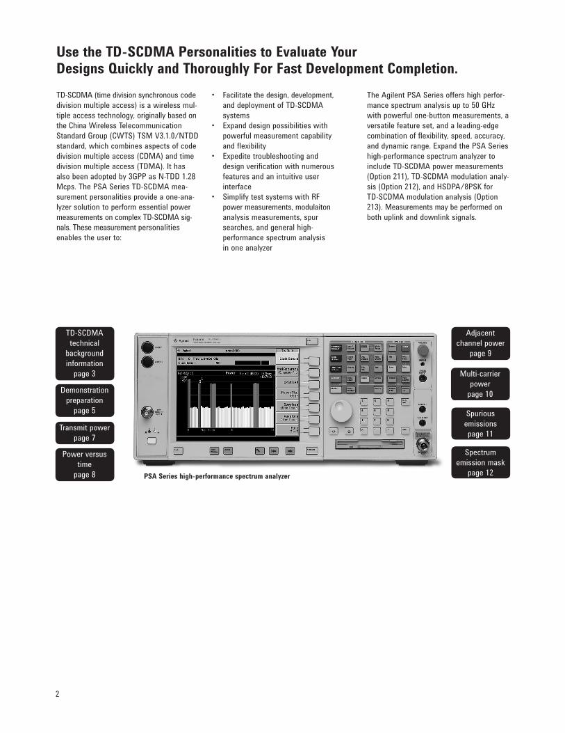
PSA Series high-performance spectrum analyzer
3
TD-SCDMA technical background information
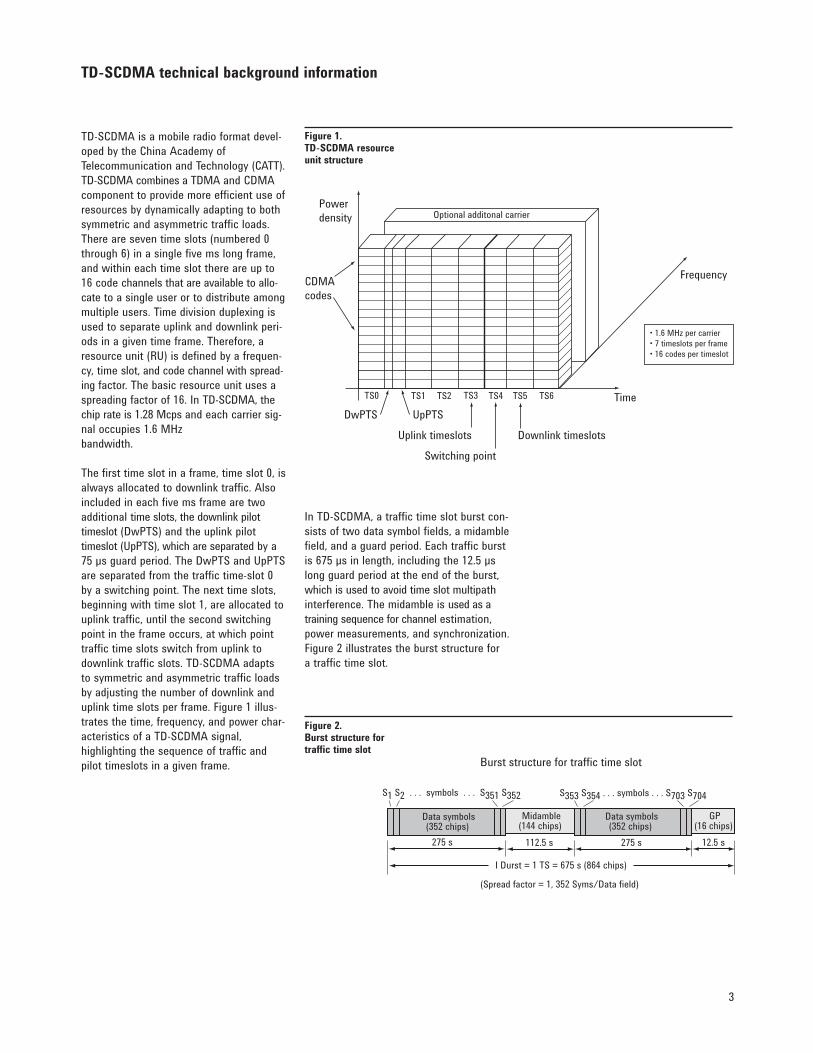
TD-SCDMA is a mobile radio format devel-oped by the China Academy of Telecommunication and Technology (CATT). TD-SCDMA combines a TDMA and CDMA component to provide more efficient use of resources by dynamically adapting to both symmetric and asymmetric traffic loads. There are seven time slots (numbered 0 through 6) in a single five ms long frame, and within each time slot there are up to 16 code channels that are available to allo-cate to a single user or to distribute among multiple users. Time division duplexing is used to separate uplink and downlink peri-ods in a given time frame. Therefore, a resourceunit(RU)isdefinedbyafrequen-cy, time slot, and code channel with spread-ing factor. The basic resource unit uses a spreading factor of 16. In TD-SCDMA, the chip rate is 1.28 Mcps and each carrier sig-nal occupies 1.6 MHz bandwidth.
The first time slot in a frame, time slot 0, is always allocated to downlink traffic. Also included in each five ms frame are two additional time slots, the downlink pilot timeslot (DwPTS) and the uplink pilot timeslot(UpPTS),whichareseparated by a 75µsguardperiod.TheDwPTSandUpPTSare separated from the traffic time-slot 0 by a switching point. The next time slots, beginning with time slot 1, are allocated to uplink traffic, until the second switching point in the frame occurs, at which point traffic time slots switch from uplink to downlink traffic slots. TD-SCDMA adapts to symmetric and asymmetric traffic loads by adjusting the number of downlink and uplink time slots per frame. Figure 1 illus-tratesthetime,frequency,andpowerchar-acteristics of a TD-SCDMA signal, highlightingthesequenceoftrafficandpilot timeslots in a given frame.
In TD-SCDMA, a traffic time slot burst con-sists of two data symbol fields, a midamble field, and a guard period. Each traffic burst is 675 µs in length, including the 12.5 µs long guard period at the end of the burst, which is used to avoid time slot multipath interference. The midamble is used as a trainingsequenceforchannel estimation, power measurements, and synchronization. Figure 2 illustrates the burst structure for a traffic time slot.
Powerdensity
CDMAcodes
Uplink timeslots
Switching point
Downlink timeslots
DwPTS UpPTSTime
Frequency
• 1.6 MHz per carrier• 7 timeslots per frame• 16 codes per timeslot
Optional additonal carrier
TS0 TS1 TS2 TS3 TS4 TS5 TS6
Figure 1.TD-SCDMA resource unit structure
Burst structure for traffic time slot
(Spread factor = 1, 352 Syms/Data field)
Data symbols(352 chips)
Data symbols(352 chips)
Midamble(144 chips)
GP(16 chips)
275 s 275 s 12.5 s112.5 s
I Durst = 1 TS = 675 s (864 chips)
S1 S2 . . . symbols . . . S351 S352 S353 S354 . . . symbols . . . S703 S704
Figure 2.Burst structure for traffic time slot
4
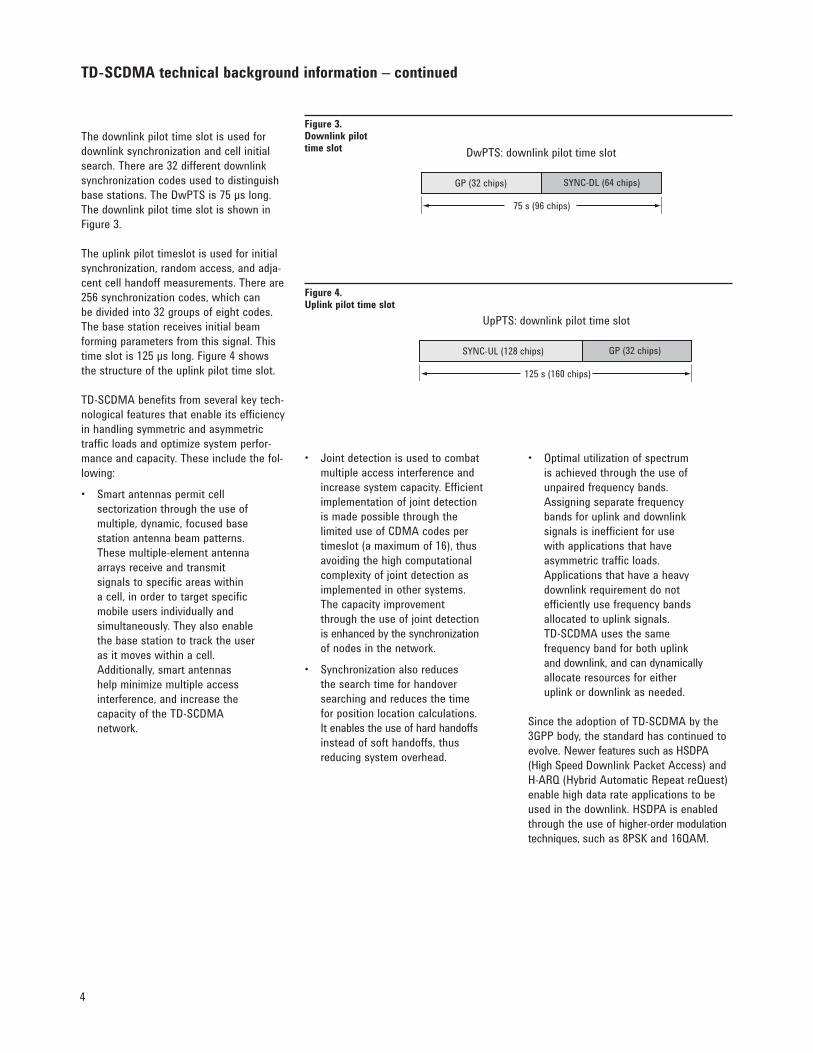
UpPTS: downlink pilot time slot
SYNC-UL (128 chips) GP (32 chips)
125 s (160 chips)
Figure 4. Uplink pilot time slot
TD-SCDMA technical background information – continued
• Optimalutilizationofspectrum is achieved through the use of unpairedfrequencybands. Assigningseparatefrequency bands for uplink and downlink signals is inefficient for use with applications that have asymmetric traffic loads. Applications that have a heavy downlinkrequirementdonot efficientlyusefrequencybands allocated to uplink signals. TD-SCDMA uses the same frequencybandforbothuplink and downlink, and can dynamically allocate resources for either uplink or downlink as needed.
Since the adoption of TD-SCDMA by the 3GPP body, the standard has continued to evolve. Newer features such as HSDPA (High Speed Downlink Packet Access) and H-ARQ(HybridAutomaticRepeatreQuest)enable high data rate applications to be used in the downlink. HSDPA is enabled through the use of higher-order modulation techniques,suchas8PSKand16QAM.
• Jointdetectionisusedtocombat multiple access interference and increase system capacity. Efficient implementation of joint detection is made possible through the limited use of CDMA codes per timeslot (a maximum of 16), thus avoiding the high computational complexity of joint detection as implemented in other systems. The capacity improvement through the use of joint detection is enhanced by the synchronization of nodes in the network.
• Synchronizationalsoreduces the search time for handover searching and reduces the time for position location calculations. It enables the use of hard handoffs instead of soft handoffs, thus reducing system overhead.
The downlink pilot time slot is used for downlink synchronization and cell initial search. There are 32 different downlink synchronization codes used to distinguish base stations. The DwPTS is 75 µs long. The downlink pilot time slot is shown in Figure 3.
The uplink pilot timeslot is used for initial synchronization, random access, and adja-cent cell handoff measurements. There are 256 synchronization codes, which can be divided into 32 groups of eight codes. The base station receives initial beam forming parameters from this signal. This time slot is 125 µs long. Figure 4 shows the structure of the uplink pilot time slot.
TD-SCDMA benefits from several key tech-nological features that enable its efficiency in handling symmetric and asymmetric traffic loads and optimize system perfor-mance and capacity. These include the fol-lowing:
• Smartantennaspermitcell sectorization through the use of multiple, dynamic, focused base station antenna beam patterns. These multiple-element antenna arrays receive and transmit signals to specific areas within a cell, in order to target specific mobile users individually and simultaneously. They also enable the base station to track the user as it moves within a cell. Additionally, smart antennas help minimize multiple access interference, and increase the capacity of the TD-SCDMA network.
DwPTS: downlink pilot time slot
GP (32 chips) SYNC-DL (64 chips)
75 s (96 chips)
Figure 3.Downlink pilot time slot
5
Demonstration preparation
All demonstrations use the PSA Series & E4438C ESG vector signal generator; key-strokes surrounded by [ ] indicate front-panel hard keys; keystrokes surrounded by indicate soft keys on display. An Agilent MXG N5182A vector signal generator may also be used.
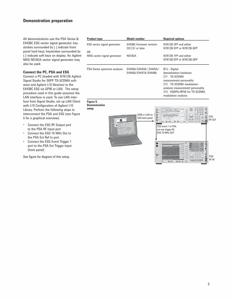
Connect the PC, PSA and ESGConnect a PC (loaded with N7612B Agilent Signal Studio for 3GPP TD-SCDMA soft-ware and Agilent I/O libraries) to the E4438C ESG via GPIB or LAN. The setup procedure used in this guide assumes the LAN interface is used. To use LAN inter-face from Signal Studio, set up LAN Client with I/O Configuration of Agilent I/O Library. Perform the following steps to interconnect the PSA and ESG (see Figure 5 for a graphical overview):
• ConnecttheESGRFOutputport tothePSARFInputport• ConnecttheESG10MHzOutto thePSAExtRefInport• ConnecttheESGEventTrigger1 port to the PSA Ext Trigger Input (front panel)
See figure for diagram of this setup.
GPIB or LAN onESG back panel
ESG event 1 to PSAext rear trigger INESG 10 MHz OUT
ESG RF OUT
PSA RF IN
Figure 5.Demonstration setup
Product type Model number Required options
ESG vector signal generator E4438C firmware revision N7612B-3FP and either C0.2.51orlater N7612B-EFPorN7612B-QFPOR MXG vector signal generator N5182A N7612B-1FP and either N7612B-EFPorN7612B-QFP
PSASeriesspectrumanalyzer E4440A/E4443A/E4445A/ B7J-Digital E4446A/E4447A/E4448A demodulation hardware 211 - TD-SCDMA measurement personality 212 - TD-SCDMA modulation analysis measurement personality 213 - HSDPA/8PSK for TD-SCDMA modulation analysis
6
E4438C ESG setupAgilent Signal Studio for 3GPP TD-SCDMA is a Windows®-based utility that simplifies the creation of standards-based or custom-ized TD-SCDMA waveforms. The Signal Studio software is used to configure the TD-SCDMA signal and then the parameters are downloaded into the ESG signal gener-ator, which creates the desired waveform.
Instructions on the ESG:Configure the desired signal parameters using the Signal Studio software on a PC. Detailed instructions on how to use the software, including examples illustrating the configuration of test signals, are provided with the Signal Studio software.
Instructions Keystrokes
On the ESG: Preset the ESG. [Preset]
ChecktheIPaddress. [Utility]GPIB/RS-232/LANLANSetupe.g., IP address 192.168.100.1
On the Signal Studio software
RuntheAgilentSignalStudiofor Double-clickontheTD-SCDMAshortcutonthe3GPP TD-SCDMA. desktop or access the program via the Windows® start menu.
Verify that the software is communicating with To establish a new connection, click on thethe instrument via the LAN TCP/IP link. System pull-down menu at the top of the Signal Studio program window. Next, select RunSystemConfigurationWizard.
On the Signal Studio software
Set the amplitude to -10 dBm. In the ESG Configuration block: Enter the value numerically or use the up/down arrows to change the default value to –10.00 dBm
Disabletheuplinkpilottimeslot(UpPTS). UnderWaveformSetup,Carrier0,clickonUpPTS. Make sure the state is set to OFF.
Send the TD-SCDMA configuration Click Applyparameters to the ESG.
Enableasignalwithonetimeslotenabled, SettingsfortheResourceUnits(RU)canas an example. be changed by clicking on each timeslot on the left-side of the window.
Demonstration preparation – continued
7
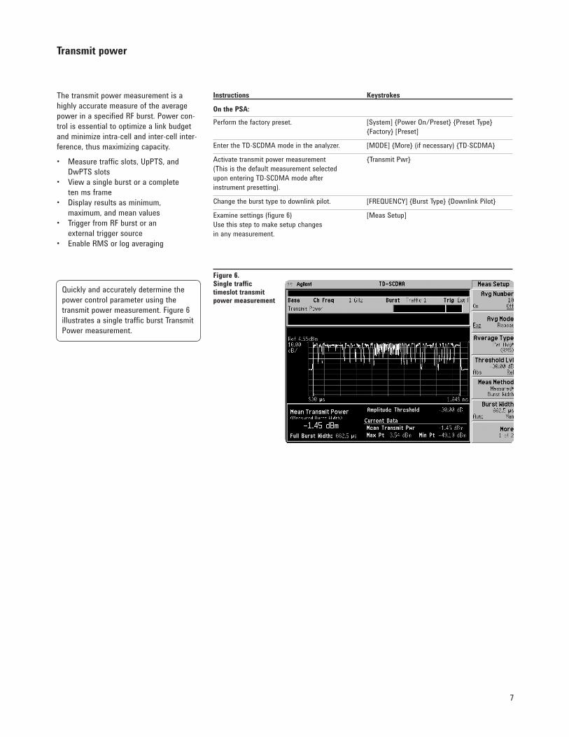
The transmit power measurement is a highly accurate measure of the average powerinaspecifiedRFburst.Powercon-trol is essential to optimize a link budget and minimize intra-cell and inter-cell inter-ference, thus maximizing capacity.
• Measuretrafficslots,UpPTS,and DwPTS slots• Viewasingleburstoracomplete ten ms frame• Displayresultsasminimum, maximum, and mean values• TriggerfromRFburstoran external trigger source• EnableRMSorlogaveraging
Transmit power
Figure 6. Single traffic timeslot transmit power measurement
Instructions Keystrokes
On the PSA: Perform the factory preset. [System] Power On/Preset Preset Type Factory [Preset]
Enter the TD-SCDMA mode in the analyzer. [MODE] More (if necessary) TD-SCDMA
Activate transmit power measurement Transmit Pwr (This is the default measurement selected upon entering TD-SCDMA mode after instrument presetting).
Changethebursttypetodownlinkpilot. [FREQUENCY]BurstTypeDownlinkPilot
Examine settings (figure 6) [Meas Setup] Usethissteptomakesetupchangesin any measurement.
Quicklyandaccuratelydeterminethepower control parameter using the transmit power measurement. Figure 6 illustrates a single traffic burst Transmit Power measurement.
8
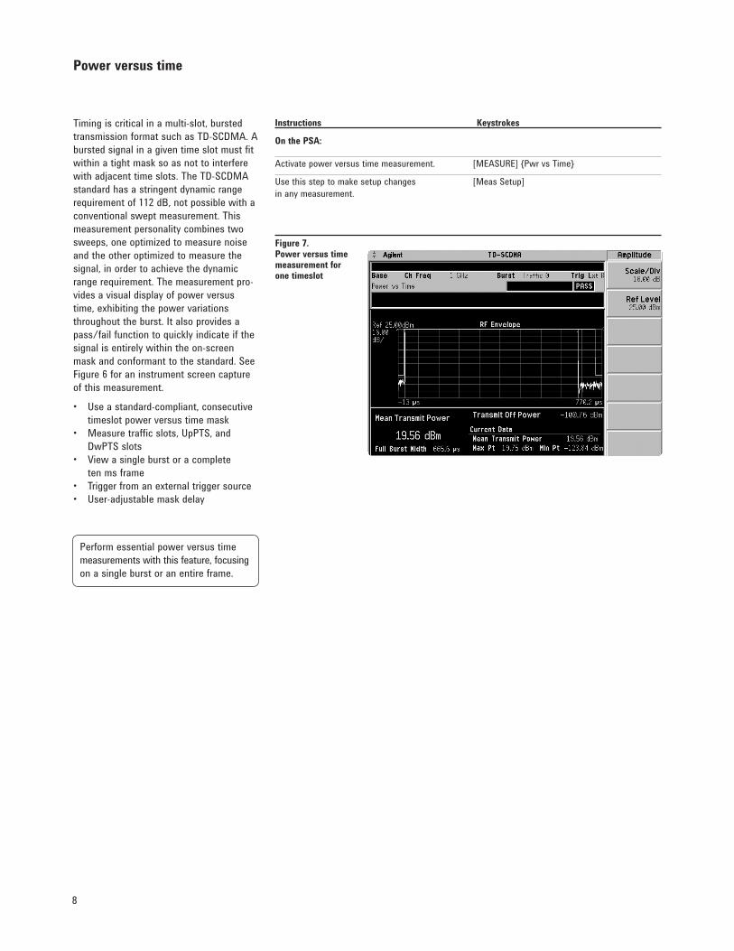
Timing is critical in a multi-slot, bursted transmission format such as TD-SCDMA. A bursted signal in a given time slot must fit within a tight mask so as not to interfere with adjacent time slots. The TD-SCDMA standard has a stringent dynamic range requirementof112dB,notpossiblewithaconventional swept measurement. This measurement personality combines two sweeps, one optimized to measure noise and the other optimized to measure the signal, in order to achieve the dynamic rangerequirement.Themeasurementpro-vides a visual display of power versus time, exhibiting the power variations throughout the burst. It also provides a pass/failfunctiontoquicklyindicateifthesignal is entirely within the on-screen mask and conformant to the standard. See Figure 6 for an instrument screen capture of this measurement.
• Useastandard-compliant,consecutive timeslot power versus time mask• Measuretrafficslots,UpPTS,and DwPTS slots• Viewasingleburstoracomplete ten ms frame• Triggerfromanexternaltriggersource• User-adjustablemaskdelay
Power versus time
Instructions Keystrokes
On the PSA:
Activatepowerversustimemeasurement. [MEASURE]PwrvsTime
Usethissteptomakesetupchanges [MeasSetup]in any measurement.
Perform essential power versus time measurements with this feature, focusing on a single burst or an entire frame.
Figure 7. Power versus time measurement for one timeslot
9
Adjacent channel power
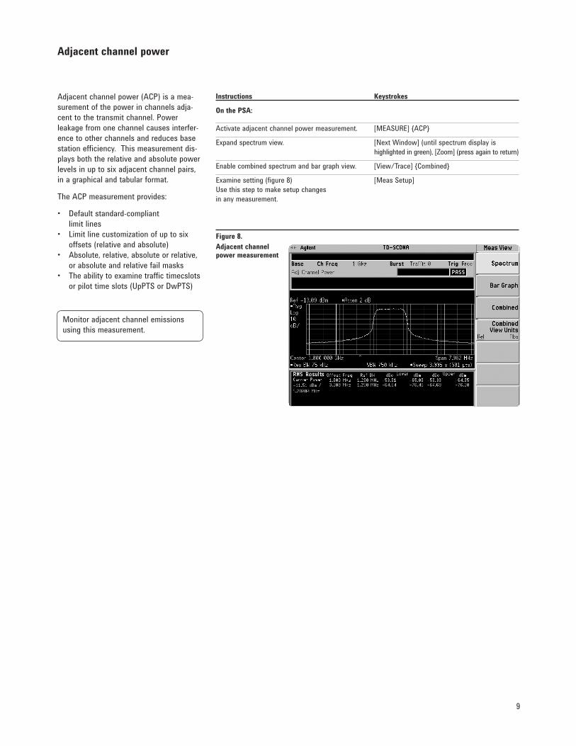
Adjacent channel power (ACP) is a mea-surement of the power in channels adja-cent to the transmit channel. Power leakage from one channel causes interfer-ence to other channels and reduces base station efficiency. This measurement dis-plays both the relative and absolute power levels in up to six adjacent channel pairs, in a graphical and tabular format.
The ACP measurement provides:
• Defaultstandard-compliant limit lines• Limitlinecustomizationofuptosix offsets (relative and absolute)• Absolute,relative,absoluteorrelative, or absolute and relative fail masks• Theabilitytoexaminetraffictimecslots orpilottimeslots(UpPTSorDwPTS)
Instructions Keystrokes
On the PSA:
Activateadjacentchannelpowermeasurement. [MEASURE]ACP
Expand spectrum view. [Next Window] (until spectrum display is highlighted in green), [Zoom] (press again to return)
Enable combined spectrum and bar graph view. [View/Trace] Combined
Examine setting (figure 8) [Meas Setup]Usethissteptomakesetupchangesin any measurement.
Monitor adjacent channel emissions using this measurement.
Figure 8.Adjacent channel power measurement

10
Instructions Keystrokes
On the PSA:
Activatemulticarrierpowermeasurement. [MEASURE]MultiCarrierPower
View results in bar graph format. [Trace/View] Combined
Eliminate tedious and time-consuming calculations using the multi-carrier power measurement.
Multi-carrier power
Multi-carrier power (MCP) is similar to adjacent channel power, but measures the power in two or more transmit channels and the power that leaks into their adja-cent channels. It is used to monitor power amplifiers that transmit two or more carriers simultaneously.
The MCP measurement:• Defaultstostandard-compliant limit lines• Supportsupto12carriers• Allowslimitlinecustomizationofupto three offsets (relative and absolute)
Figure 9.Multi-carrier power measurement
11
Spurious emissions
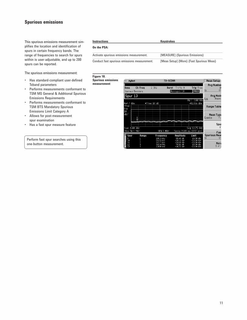
This spurious emissions measurement sim-plifies the location and identification of spursincertainfrequencybands.Therangeoffrequenciestosearchforspurswithin is user-adjustable, and up to 200 spurs can be reported.
The spurious emissions measurement:
• Hasstandard-compliantuser-defined Txband parameters• Performsmeasurementsconformantto TSM MS General & Additional Spurious EmissionsRequirements• Performsmeasurementsconformantto TSM BTS Mandatory Spurious Emissions Limit Category A • Allowsforpost-measurement spur examination• Hasafastspurmeasurefeature
Figure 10. Spurious emissions measurement
Instructions Keystrokes
On the PSA:
Activatespuriousemissionsmeasurement. [MEASURE]SpuriousEmissions
Conduct fast spurious emissions measurement. [Meas Setup] More Fast Spurious Meas
Perform fast spur searches using this one-button measurement.
12
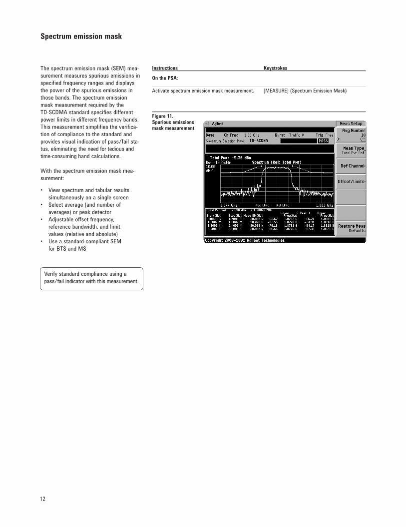
The spectrum emission mask (SEM) mea-surement measures spurious emissions in specifiedfrequencyrangesanddisplaysthe power of the spurious emissions in those bands. The spectrum emission maskmeasurementrequiredbytheTD-SCDMA standard specifies different powerlimitsindifferentfrequencybands.This measurement simplifies the verifica-tion of compliance to the standard and provides visual indication of pass/fail sta-tus, eliminating the need for tedious and time-consuming hand calculations.
With the spectrum emission mask mea-surement:
• Viewspectrumandtabularresults simultaneously on a single screen• Selectaverage(andnumberof averages) or peak detector• Adjustableoffsetfrequency, reference bandwidth, and limit values (relative and absolute)• Useastandard-compliantSEM for BTS and MS
Spectrum emission mask
Figure 11. Spurious emissions mask measurement
Instructions Keystrokes
On the PSA:
Activatespectrumemissionmaskmeasurement. [MEASURE]SpectrumEmissionMask
Verify standard compliance using a pass/fail indicator with this measurement.
13
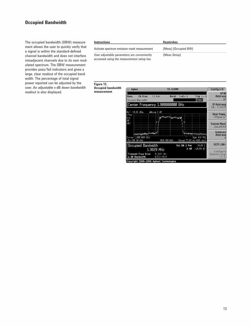
The occupied bandwidth (OBW) measure-mentallowstheusertoquicklyverifythata signal is within the standard-defined channel bandwidth and does not interfere intoadjacent channels due to its own mod-ulated spectrum. The OBW measurement provides pass/fail indicators and gives a large, clear readout of the occupied band-width. The percentage of total signal power reported can be adjusted by the user. An adjustable x-dB down bandwidth readout is also displayed.
Occupied Bandwidth
Figure 12. Occupied bandwidthmeasurement
Instructions Keystrokes
Activate spectrum emission mask measurement [Meas] Occupied BW
User-adjustableparametersareconveniently MeasSetupaccessed using the measurement setup key
14
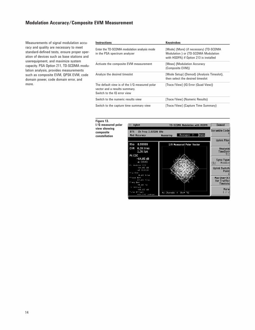
Measurements of signal modulation accu-racyandqualityarenecessarytomeetstandard-defined tests, ensure proper oper-ation of devices such as base stations and userequipment,andmaximizesystemcapacity. PSA Option 211, TD-SCDMA modu-lation analysis, provides measurements suchascompositeEVM,QPSKEVM,codedomain power, code domain error, and more.
Modulation Accuracy/Composite EVM Measurement
Figure 13. I/Q measured polar view showingcomposite constellation
Instructions Keystrokes
Enter the TD-SCDMA modulation analysis mode [Mode] More (if necessary) TD-SCDMAin the PSA spectrum analyzer Modulation or TD-SCDMA Modulation with HSDPA if Option 213 is installed
Activate the composite EVM measurement [Meas] Modulation Accuracy (Composite EVM)
Analyze the desired timeslot [Mode Setup] Demod Analysis Timeslot, then select the desired timeslot
ThedefaultviewisoftheI/Qmeasuredpolar [Trace/View]IQError(QuadView)vector and a results summary. SwitchtotheIQerrorview
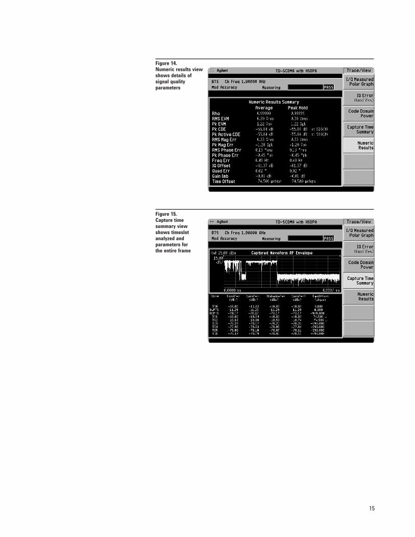
Switchtothenumericresultsview [Trace/View]NumericResults
Switch to the capture time summary view [Trace/View] Capture Time Summary
15
Figure 15. Capture time summary view shows timeslotanalyzed andparameters forthe entire frame
Figure 14. Numeric results viewshows details ofsignal qualityparameters

16
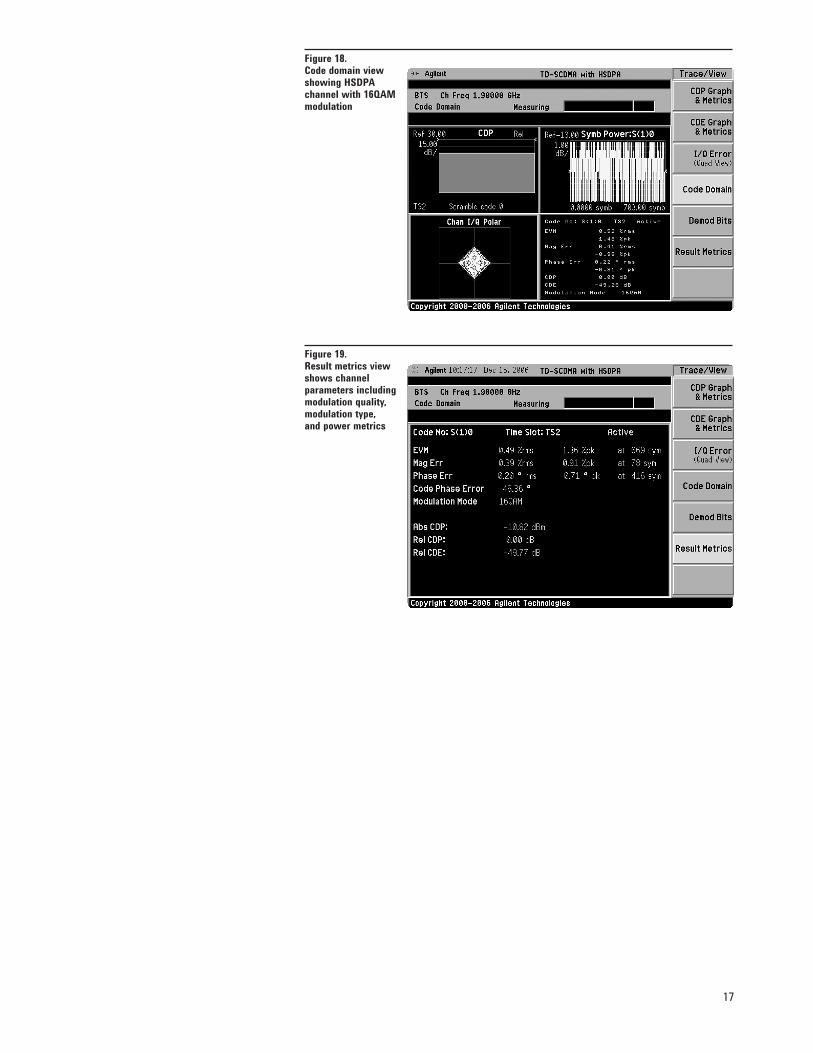
The code domain measurement provides results such as absolute and relative code domain power, code domain error, number of active channels, channel constellation anderror views, symbol power, demod bits, and more. If Option 213 is installed, then analysis of HSDPA/8PSK signals is possi-ble.
Code Domain Measurements
Instructions Keystrokes
Activate the code domain measurement [Meas] Code Domain
Ensure the desired timeslot is selected [Mode Setup] Demod Analysis Timeslot, then select the desired timeslot
ThedefaultviewisoftheCDPgraphandmetrics [Trace/View]IQError(QuadView)windows.SwitchtotheIQerrorview
Switch to the code domain view. [Trace/View] Code DomainThe modulaiton type is automatically detected
Switchtotheresultmetricsview [Trace/View]ResultMetrics
Figure 17. I/Q error view shows channelmagnitude error,phase error, and EVM
Figure 16. Code domain powerview shows activeand inactive channels,and power metricsof active channels
17
Figure 19. Result metrics view shows channel parameters includingmodulation quality,modulation type,and power metrics
Figure 18. Code domain viewshowing HSDPAchannel with 16QAMmodulation
18
Specifications GeneralStandards compliant 1.28 Mcps 3GPP N-TDDDevice types: MS, BTSAutomatic Input & ref level settingUserdefinedTxbandstart/stop
Option 211 specifications summaryPower versus timeMask supports consecutive timeslots (standards compliant)Bursttypes:traffic,UpPTS,DwPTSSupport full radio frame mask (10 ms)Tx Off power resultResulttype:min,max,meanStandards compliant dynamic range1 (–82 dBm off power)Trigger: External (front or rear)Mask user definable2 Average typeAverage modeMarkers: normal, deltaNOTE:RRCfilternotsupportedTransmit powerBursttypes:traffic,UpPTS,DwPTSSupport full radio frame mask (10 ms)Methods: above threshold, burst widthResulttype:min,max,meanTrigger:xxternal(frontorrear),RFburstAverage typeAverage modeMarkers: normal, deltaNOTE:Rootraisedcosine(RRC)filternotsupportedAdjacent channel power (ACP)Standards compliant default limits RRCfiltersupportAverage typeLimits customizable up to six offsets (relative and absolute)Resultrepresentation:totalpowerref,PSDrefMeets“minimumACLRrequirement(limitvalues)”Multi channel power (MCP)Standards compliant default limits Support of up to 12 carriersRRCfiltersupportAverage typeLimits customizable up to three offsets (relative and absolute)Meets“minimumACLRrequirement(limitvalues)”Spurious emissionsStandard-compliant based on user defined Tx band parameters“MSgeneral&additionalspuriousemissionsrequirements”“BSmandatoryspuriousemissionslimitscategoryA”UserdefinablerangetableSupport trace averagingPost measurement spur examinationSpectrum emission maskStandard-compliant based on user defined Tx band parametersStandard-compliant SEM for MS and BTS(Note: BTS max output power < 31 dBm)Limits customizable (relative and absolute)Markers: normal, deltaOccupied bandwidthUser-adjustableoccupiedbandwidthpowerpercentageSupports trace averagingAdjustable x dB bandwidth readout
1.Option1DSrequired2. Mask is definable using remote commands only

19
Specifications– continued
Options 212 and 213 specifications summaryCode domainRelativepoweraccuracy<0.1dB(nominal)Modulation accuracyComposite EVM accuracy (1 DPCH per timeslot) ±1.0 % (nominal)Composite EVM accuracy (4 HS-PDSCH per timeslot) ±1.0 % (nominal)
20
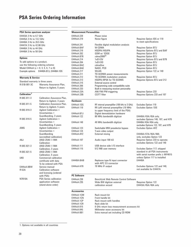
PSA Series Ordering Information
1. Options not available in all countries
PSA Series spectrum analyzerE4443A 3 Hz to 6.7 GHzE4445A 3 Hz to 13.2 GHzE4440A 3 Hz to 26.5 GHzE4447A 3 Hz to 42.98 GHzE4446A 3 Hz to 44 GHzE4448A 3 Hz to 50 GHz
OptionsTo add options to a product, use the following ordering scheme:Model E444xA (x = 0, 3, 5, 6, 7 or 8)ExampleoptionsE4440A-B7J,E4448A-1DS
Warranty & ServiceStandard warranty is three years.R-51B-001-3C WarrantyAssurancePlan, ReturntoAgilent,5years
Calibration 1
R-50C-011-3 CalibrationAssurancePlan, ReturntoAgilent,3yearsR-50C-011-5 CalibrationAssurancePlan, ReturntoAgilent,5yearsR-50C-016-3 AgilentCalibration+ Uncertainties+ Guardbanding, 3 yearsR-50C-016-5 AgilentCalibration+ Uncertainties+ Guardbanding, 5 yearsAMG AgilentCalibration+ Uncertainties+ Guardbanding (accredited calibration) A6J ANSIZ540-1-1994 CalibrationR-50C-021-3 ANSIZ540-1-1994 Calibration, 3 yearsR-50C-021-5 ANSIZ540-1-1994 Calibration, 5 yearsUK6 Commercialcalibration certificate with data To be ordered with PSAE444xA-0BW Service manualR-52A Calibrationsoftware and licensing (ordered with PSA)N7810A PSA Series calibration application software (stand-alone order)
Measurement PersonalitiesE444xA-226 Phase noise E444xA-219 Noisefigure RequiresOptionIDSor110 to meet specificationsE444xA-241 Flexible digital modulation analysisE444xA-BAF W-CDMA RequiresOptionB7JE444xA-210 HSDPA/HSUPA RequiresOptionsB7JandBAFE444xA-202 GSMw/EDGE RequiresOptionB7JE444xA-B78 cdma2000® RequiresOptionB7JE444xA-214 1xEV-DV RequiresOptionsB7JandB78E444xA-204 1xEV-DO RequiresOptionB7JE444xA-BAC cdmaOne RequiresOptionB7JE444xA-BAE NADC,PCD RequiresOptionB7JE444xA-217 WLAN RequiresOption122or140E444xA-211 TD-SCDMA power measurements E444xA-212 TD-SCDMAmodulationanalysis RequiresOptionB7JE444xA-213 HSDPA/8PSKforTD-SCDMA RequiresOptionsB7Jand212E444xA-215 External source controlE444xA-266 Programming code compatibility suite E444xA-233 Built-in measuring receiver personality E444xA-23A AM/FM/PMtriggering RequiresOption233E444xA-23B CCITTfilter RequiresOptions233and107
HardwareE444xA-1DS RFinternalpreamplifier(100kHzto3GHz) Excludes Option 110E444xA-110 RF/µWinternalpreamplifier(10MHz ExcludesOption1DS toupperfrequencylimitofthePSA) E444xA-B7J Digitaldemodulationhardware E444xA-122 80 MHz bandwidth digitizer E4440A/43A/45A only, excludes Options 140, 107, and H70E444xA-140 40 MHz bandwidth digitizer E4440A/43A/45A only, excludes Options 122, 107, and H70E444xA-123 Switchable MW preselector bypass ExcludesOptionAYZE444xA-124 Y-axisvideooutputE444xA-AYZ Externalmixing E4440A/47A/46A/48A only, excludes Option 123 E444xA-107 Audioinput100kΩ RequiresOption233tooperate; excludes Options 122 and 140 E444xA-111 USBdevicesideI/OinterfaceE444xA-115 512 MB user memory Excludes Option 117; shipped standard in all PSA instruments withserialnumberprefix≥MY4615 unless Option 117 is installedE4440A-BAB Replacestype-Ninputconnector E4440A with APC 3.5 connector E444xA-H70 70 MHz IF output Excludes Options 122 and 140; not available for E4447A
PC SoftwareE444xA-230 BenchLinkWebRemoteControlSoftwareE444xA-235 WideBWdigitizerexternal RequiresOption122 calibration wizard E4443A/45A/40A only
Accessories E444xA-1CM RackmountkitE444xA-1CN Front handle kit E444xA-1CP RackmountwithhandlesE444xA-1CR RackslidekitE444xA-015 6 GHz return loss measurement accessory kitE444xA-045 Millimeter wave accessory kit E444xA-0B1 ExtramanualsetincludingCDROM
21
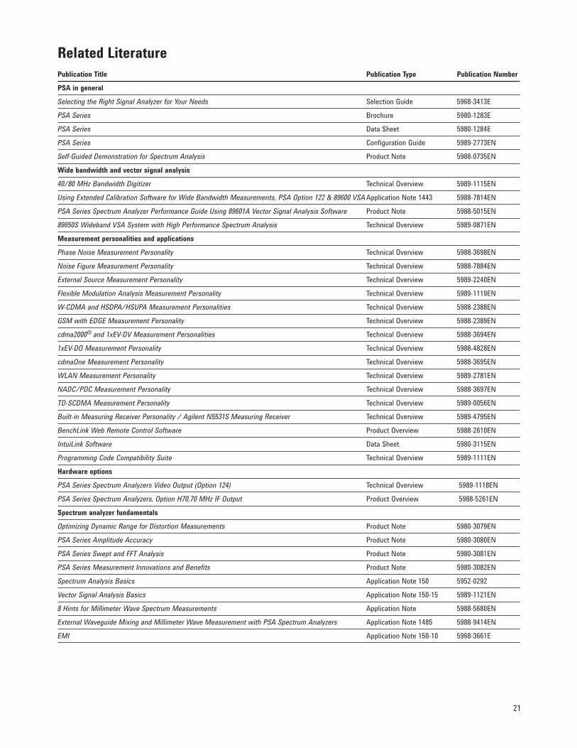
Related LiteraturePublication Title Publication Type Publication Number
PSA in general
Selecting the Right Signal Analyzer for Your Needs Selection Guide 5968-3413E
PSA Series Brochure 5980-1283E
PSA Series Data Sheet 5980-1284E
PSA Series Configuration Guide 5989-2773EN
Self-Guided Demonstration for Spectrum Analysis Product Note 5988-0735EN
Wide bandwidth and vector signal analysis
40/80 MHz Bandwidth Digitizer Technical Overview 5989-1115EN
Using Extended Calibration Software for Wide Bandwidth Measurements, PSA Option 122 & 89600 VSA Application Note 1443 5988-7814EN
PSA Series Spectrum Analyzer Performance Guide Using 89601A Vector Signal Analysis Software Product Note 5988-5015EN
89650S Wideband VSA System with High Performance Spectrum Analysis Technical Overview 5989-0871EN
Measurement personalities and applications
Phase Noise Measurement Personality Technical Overview 5988-3698EN
Noise Figure Measurement Personality Technical Overview 5988-7884EN
External Source Measurement Personality Technical Overview 5989-2240EN
Flexible Modulation Analysis Measurement Personality Technical Overview 5989-1119EN
W-CDMA and HSDPA/HSUPA Measurement Personalities Technical Overview 5988-2388EN
GSM with EDGE Measurement Personality Technical Overview 5988-2389EN
cdma2000® and 1xEV-DV Measurement Personalities Technical Overview 5988-3694EN
1xEV-DO Measurement Personality Technical Overview 5988-4828EN
cdmaOne Measurement Personality Technical Overview 5988-3695EN
WLAN Measurement Personality Technical Overview 5989-2781EN
NADC/PDC Measurement Personality Technical Overview 5988-3697EN
TD-SCDMA Measurement Personality Technical Overview 5989-0056EN
Built-in Measuring Receiver Personality / Agilent N5531S Measuring Receiver Technical Overview 5989-4795EN
BenchLink Web Remote Control Software Product Overview 5988-2610EN
IntuiLink Software Data Sheet 5980-3115EN
Programming Code Compatibility Suite Technical Overview 5989-1111EN
Hardware options
PSA Series Spectrum Analyzers Video Output (Option 124) Technical Overview 5989-1118EN
PSA Series Spectrum Analyzers, Option H70,70 MHz IF Output Product Overview 5988-5261EN
Spectrum analyzer fundamentals
Optimizing Dynamic Range for Distortion Measurements Product Note 5980-3079EN
PSA Series Amplitude Accuracy Product Note 5980-3080EN
PSA Series Swept and FFT Analysis Product Note 5980-3081EN
PSA Series Measurement Innovations and Benefits Product Note 5980-3082EN
Spectrum Analysis Basics Application Note 150 5952-0292
Vector Signal Analysis Basics Application Note 150-15 5989-1121EN
8 Hints for Millimeter Wave Spectrum Measurements Application Note 5988-5680EN
External Waveguide Mixing and Millimeter Wave Measurement with PSA Spectrum Analyzers Application Note 1485 5988-9414EN
EMI Application Note 150-10 5968-3661E
www.agilent.com
For more information on Agilent Technologies’ products, applications or services, please contact your local Agilent office. The complete list is available at:www.agilent.com/find/contactus
AmericasCanada (877) 894 4414 Brazil (11) 4197 3600Mexico 01800 5064 800 UnitedStates (800)8294444Asia PacificAustralia 1 800 629 485China 800 810 0189Hong Kong 800 938 693India 1 800 112 929Japan 0120(421)345Korea 080 769 0800Malaysia 1 800 888 848Singapore 1 800 375 8100Taiwan 0800 047 866Other AP Countries (65) 375 8100Europe & Middle EastBelgium 32 (0) 2 404 93 40 Denmark 45 45 80 12 15Finland 358 (0) 10 855 2100France 0825 010 700* *0.125 €/minuteGermany 49 (0) 7031 464 6333 Ireland 1890 924 204Israel 972-3-9288-504/544Italy 39 02 92 60 8484Netherlands 31 (0) 20 547 2111Spain 34 (91) 631 3300Sweden 0200-88 22 55UnitedKingdom 44(0)1189276201
For other unlisted countries:www.agilent.com/find/contactus(BP-09-27-13)
Product specifications and descriptions in this document subject to change without notice.
© Agilent Technologies, Inc. 2013PublishedinUSA,November25,20135989-0056EN
myAgilent
www.agilent.com/find/myagilentA personalized view into the information most relevant to you.
www.lxistandard.org
LAN eXtensions for Instruments puts the power of Ethernet and the Web inside your test systems. Agilent is a founding member of the LXI consortium.
Three-Year Warranty
www.agilent.com/find/ThreeYearWarrantyBeyond product specification, changing the ownership experience.Agilent is the only test and measurement company that offers three-year warranty on all instruments, worldwide
Agilent Assurance Plans
www.Agilent.com/find/AssurancePlansFive years of protection and no budgetary surprises to ensure your instruments are operating to specifications and you can continually rely on accurate measurements.
www.agilent.com/quality
Agilent Electronic Measurement GroupDEKRACertifiedISO9001:2008 QualityManagementSystem
Agilent Channel Partners
www.agilent.com/find/channelpartnersGet the best of both worlds: Agilent’s measurement expertise and product breadth, combined with channel partner convenience.
cdma2000 is a registered certification mark of the Telecommunications Industry Association. Used under license.