Agilent Automotive Electronics - Advanced Test Equipment Rentals
76
Agilent Automotive Electronics 10 Application Notes on Design Debug and Functional Test Advanced Test Equipment Rentals www.atecorp.com 800-404-ATEC (2832) ® E s t a blishe d 1 9 8 1
Transcript of Agilent Automotive Electronics - Advanced Test Equipment Rentals

Agilent Automotive Electronics10 Application Notes on Design Debug
and Functional Test
Advanced Test Equipment Rentalswww.atecorp.com 800-404-ATEC (2832)
®
Established 1981

If you are designing, manufacturing and testing automotive electronics, you face
a lot of pressure. Most likely, you need to meet aggressive time-to-market goals.
At the same time, you're juggling demands for higher quality, faster throughput
and lower costs. We understand, and welcome the opportunity to help you
develop and test your electronic products faster and within cost targets,
while meeting your quality goals. We offer a broad set of robust test tools –
the broadest offering in the automotive electronics test industry – to help you.
We assembled this collection of application notes to give you insight into
how some of our test products can help you. Whether you want to shave
milliseconds from your test throughput times or find a new way to uncover
signal integrity problems in an automotive serial bus, we trust you'll find
some nuggets here that will make your job easier.
You can count on Agilent, the premier test vendor for
automotive electronics test.
Best regards,
Kari Fauber
Agilent Automotive Initiative Manager
Automotive Electronics: 10 Application Notes on Design Debug and Functional Test
Introduction

i
Automotive Electronics Design Debug
Application note 1: Using an Agilent 6000 Series MSO to Debug an
Automotive CAN Bus
Automotive Electronics Functional Test
Application note 2: Increase Automotive ECU Test Throughput
Application note 3: Automotive Electronic Functional Test Using
Agilent System Components
Application note 4: Testing Antilock Brakes and Traction Control with the
Agilent TS-5000 Family of Automotive Electronics Functional
Test Systems
Application note 5: Testing Remote Keyless Entry Systems with the
Agilent TS-5000 Family of Automotive Electronics Functional
Test Systems
Application note 6: Testing Supplemental Restraint Systems with the
Agilent TS-5000 Family of Automotive Electronics Functional
Test Systems
Application note 7: Using Agilent 6690A Series System DC Power Supplies
for Automobile Battery Simulation
Application note 8: Agilent TS-5020 Tire Pressure Monitoring System (TPMS)
Application note 9: Agilent TS-5400 Series II Automotive Electronics Functional
Test System
Application note 10: Agilent TS-5020 Automotive Electronics Functional
Test Systems

ii
Application Note Summaries
Automotive Design Debug
Application note 1
Using an Agilent 6000 Series MSO to Debug an
Automotive CAN Bus
This application note shows a typical debugging
methodology designed to uncover signal integrity problems
in a CAN-based automotive system. We use an intermittent
problem in an automatic windshield-wiper to illustrate how
you can use a mixed signal oscilloscope (MSO) to more
effectively and efficiently turn on and debug an embedded
mixed-signal design in an automobile. You will see how
to synchronize on and capture a CAN differential signal
that digitally transmits analog sensor data to an ECU.
We demonstrate how you can use an MSO to repetitively
capture and measure the output amplitude of a remote
analog input sensor, while also capturing multiple
SPI control signals within the ECU.
Automotive Functional Test
Application note 2
Increase Automotive ECU Test Throughput
Every second of test time counts in the competitive
automotive electronics marketplace. Testing at multiple
bias voltage levels is a necessary but time-consuming part
of ECU testing. Most system DC sources require significant
time to change and settle to a new output setting, adding
several seconds to the overall test time. Learn what you
can do to reduce command processing time and output
response time and decrease the number of output voltage
transitions. The overall test time reduction you can achieve
could have a significant impact on your cost of test.
Application note 3
Automotive Electronic Functional Test Using Agilent
System Components
This application note shows you how to use Agilent
bench instruments to create a reusable functional test
system for low-frequency automotive modules. The
illustrated test system uses LAN as an effective and
inexpensive way to transfer data among the instruments
and connect to virtually any instrument (GPIB- and
LAN-based instruments, synthetic instruments and
cardcage instruments). The illustrated test system
uses an Agilent 34980A multi-function switch
measure unit as the core.
Application note 4
Testing Antilock Brakes and Traction Control with the
Agilent TS-5000 Family of Automotive Electronics
Functional Test Systems
If you manufacture electronic control modules (ECMs)
for antilock brake and traction control systems, you know
that functional testing of your products is critical to ensure
reliability and that reliability is directly related to safety.
This application note discusses some manufacturing func-
tional tests you can perform on your antilock brake and
traction control system ECMs using the Agilent TS-5400
Series II electronics functional test platform, including
testing variable reluctance sensors, characterizing wheel
speed thresholds, characterizing solenoid driver electronics,
verifying "smart driver" response, and testing pump
motor drivers.

iii
Application note 5
Testing Remote Keyless Entry Systems with the
Agilent TS-5000 Family of Automotive Electronics
Functional Test Systems
This application note discusses some of the manufacturing
functional tests you can perform on remote keyless entry
systems and immobilizers using the Agilent TS-5000 family
test systems, including checking the signal strength of
the key fob amplitude and center frequency, verifying
transmitter leakage current during active RF transmission,
verifying RKE functionality, measuring the time between
pressing the key fob and the resulting action, and verifying
proper orientation of the transponder IC in the key fob.
Application note 6
Testing Supplemental Restraint Systems with the
Agilent TS-5000 Family of Automotive Electronics
Functional Test Systems
Unlike other automotive electronics, airbags typically
are built to operate only once, so running a full test of
the airbag in production is virtually impossible. However,
various manufacturing tests can help you ensure the
reliability and system integrity of your supplemental
restraint systems. The application note discusses some
of the functional tests you can perform on supplemental
restraint systems using the AgilentTS-5000 family test
systems, including testing the ECM's serial communications;
detecting sensor opens, shorts or shorts-to-chassis;
verifying occupancy-sensor switch operations;
testing the battery voltage; and testing the
firing loop for airbag deployment.
Application note 7
Using Agilent 6690A Series System DC Power Supplies for
Automobile Battery Simulation
The standard voltage for automobile batteries is moving
to 42 V. However, because of load changes during the
operation of the vehicle, that voltage may reach up to
60 V or go as low as 25 V. The new 42-V battery will have
different requirements for duty cycle and total power
capability than 12-V batteries have. Under start/stop
scenarios of future vehicles, the number of starts and
stops that the battery will endure could increase by a
factor of more than 10. This loading puts more strain on
the battery and other car components. Find out how you
can use the Agilent 6692A power supply for simulating the
battery under all loading conditions. This power supply can
also be used to test electronic equipment while simulating
actual battery voltage fluctuations.
Application note 8
Agilent TS-5020 Tire Pressure Monitoring System (TPMS)
Tire pressure monitoring is an important safety feature.
Conventional TPMS modules consist of pressure and
temperature sensors attached to each wheel, data
transmitters and a central receiver. Testing the transmitter
module involves checking the signal power level and
frequency deviation (FSK), making burst measurements
(ASK) and demodulating the ASK/FSK signal. Learn how
the Agilent TS-5020 TPMS testing solution can help you
accomplish these tasks and more.
Application note 9
Agilent TS-5400 Series II Automotive Electronics
Functional Test System
Testing automotive ECMs requires an understanding of
the design and manufacturing requirements. This product
note discusses the general requirements for testing an
automotive ECM and explains how the TS-5400 Series II
test system can help you meet those requirements with
"just enough test." It describes the benefits of using the
TS-5400 platform and shows you how you can reduce test
development time, save on capital expenditures and reduce
total test cost, increase your flexibility and plan for
future growth.
Application note 10
Agilent TS-5020 Automotive Electronics Functional
Test Systems
Producing quality ECMs can be a challenge when you are
trying to get your products to market quickly and deliver
them at a competitive cost. This product note tells how the
TS-5020 automotive electronics functional test system can
help you get products to market faster and at a lower cost
without sacrificing quality. It discusses the unique attrib-
utes of automotive functional testing, test requirements and
methodologies, and the advantages of Agilent TestExec SL
software, which comes with the TS-5020.

iv

Using an Agilent 6000 Series MSO
To Debug an Automotive CAN Bus
Application Note 1576
Table of Contents
Introduction . . . . . . . . . . . . . . . . . . . . . . 2
What is an MSO? . . . . . . . . . . . . . . . . . 3
Verifying proper operation . . . . . . . . . . 4
of an automatic
windshield-wiper system
Hardware-accelerated . . . . . . . . . . . . 5
CAN decode reveals an
infrequent problem
Triggering the MSO on . . . . . . . . . . . . 6
error frames reveals a
signal-integrity problem
Triggering the MSO on the . . . . . . . . . 8
random glitch reveals the
source of the problem
Summary . . . . . . . . . . . . . . . . . . . . . . . . 9
Glossary. . . . . . . . . . . . . . . . . . . . . . . . 10
Related Literature . . . . . . . . . . . . . . . . 11
1

1-2
To improve efficiency of systemcommunication and to reducecost, all of today’s automotivedesigns employ a variety of serialbus communication protocols.The I2C and SPI protocols aremost often used for chip-to-chipcommunication within electroniccontrol units (ECUs). For long-haul serial communicationbetween various automotivesubsystems such as anti-lockbrakes, airbag deployment, enginecontrol, and GPS navigation, theCAN, LIN, and MOST protocolsare the most popular serial busesimplemented in today’s vehicles,as shown in Figure 1.Unfortunately, long-haulcommunication is oftensusceptible to signal integrityproblems caused by the naturallyharsh environment found inautomobiles, including signalinterference from ignitionsystems and random system
noise, which can sometimescreate errors during criticalcommunication cycles.
By definition, automotiveelectronic systems are embeddedmixed-signal systems becausethey feature multiple analogsensors and analog motorcontrols under digital control. Foryears, traditional oscilloscopeshave been the primary tool-of-choice among automotiveelectronic system designengineers to measure the qualityof both analog and digital signals.But traditional analog and digitaloscilloscopes have manylimitations, including lack ofcomplex serial triggering andlimited input channels ofacquisition. However, a new classof measurement tools calledmixed signal oscilloscopes(MSOs) offers many advantagesfor debugging and verifying
proper operation of today’sautomotive designs.
To illustrate the uniqueadvantages of Agilent 6000 seriesMSOs, this application noteshows a typical debuggingmethodology designed to uncoversignal integrity problems in aCAN-based automotive system.While synchronizing on andcapturing a CAN differentialsignal that digitally transmitsanalog sensor data to an ECU, theMSO was also used to repetitivelycapture and measure the outputamplitude of a remote analoginput sensor. At the same time,the MSO also was used to capturemultiple SPI control signalswithin the ECU. But before weexplore this particularautomotive CAN design andexplaining how the MSO was usedto debug and discover a signalintegrity problem, let's firstdefine what we mean by "MSO."
Introduction
Figure 1:
Typical distributed
automotive electronic
system under serial
bus control

1-3
What is an MSO?
An MSO is a hybrid testinstrument that combines all ofthe measurement capabilities of adigital storage oscilloscope (DSO)with some of the measurementcapabilities of a logic analyzer,along with some serial protocolanalysis — into a single,synergistic instrument. With anMSO, you are able to see multipletime-aligned analog, parallel-digital, and serially decodedwaveforms on the same display,as shown in Figure 2. Althoughmany of today’s traditionaloscilloscopes have limitedtriggering capabilities, some oftoday’s MSOs includesophisticated serial triggeringand protocol decode analysis thatare optimized for automotiveelectronic system debug.
MSOs typically lack the largenumber of digital acquisitionchannels of full-fledged logicanalyzers and also lack the higherabstraction levels of analysisprovided by serial protocolanalyzers. But the relativesimplicity of MSOs allows you touse them with ease and avoid thecomplexities involved inoperating logic analyzers andprotocol analyzers. In fact, one of the primary advantages of anMSO is its use model. You use anMSO in much the same way youuse an oscilloscope. And becauseMSOs are highly integrated, theyare much easier to use thanloosely tethered two-box mixed-signal measurementsolutions consisting of either ascope linked to a logic analyzer or
a scope linked to a serial busprotocol analyzer. A good MSO,such as Agilent’s MSO6000, isuser-friendly, provides fastwaveform update rates,includes serial triggering andanalysis, and operates muchlike an oscilloscope — not like alogic analyzer or protocolanalyzer.
Figure 2: Agilent’s 6000 Series mixed signal oscilloscope (MSO)

1-4
Verifying proper operation of an automatic windshield-wiper system
Before integrating a new embed-ded design into an automobile, anAgilent MSO was first used in thelab environment to verify propercircuit and protocol operation ofa prototype automatic wind-shield-wiper system. Figure 3shows multiple time-correlatedanalog and digital signals fromthe prototype system capturedand displayed on an MSO6104A.The channel-1 waveform (toptrace) is the differential CAN bussignal that communicates to various remote subsystemsincluding the windshield-wipersystem. The channel-2 waveform(middle trace) shows the analogoutput signal level of a remoterain sensor that optically detectsthe amount of rain/snow strikingthe windshield. Also shown arevarious time-correlated SPI con-trol signals (traces shown nearthe bottom of the scope’s display)within the ECU including CLOCK,DATA, CS, and an INTERRUPTsignal — all captured using someof the MSO’s available sixteenlogic-timing channels. The multi-colored bus trace at the bottom ofthis oscilloscope’s display showstime-correlated decoded informa-tion of CAN packets captured ona user-selected CAN acquisitionchannel, which in this case waschannel-1.
In this particular design, theinstantaneous output amplitudeof the remote analog sensor isconverted to a digital value usingan analog-to-digital converter(ADC), and then it is seriallytransmitted to the ECU as a sin-gle data byte within a particulardata frame (07FHEX). To capture
repetitive transmissions of thissensor’s output and verify proper
operation of the prototype, theMSO was initially set up to triggeron the CAN data frame 07FHEX,
as shown in Figure 3. The analogsensor’s output value is alwaystransmitted in this frame. Withthis oscilloscope setup condition,the automotive design engineerwas able to easily measure theanalog amplitude of the sensor’soutput (3.41 V) while monitoringand verifying the data value(BHEX) that was actually trans-
mitted within the CAN packet.While testing this prototype auto-matic wiper system in the lab, noproblems were observed, and theCAN differential signal appears tobe nearly noise-free.
Unfortunately, when this automo-tive subsystem was integratedinto the automobile, the automat-ic wiper system performed unreli-ably, and it was determined thatthe data value received by theECU did not always match thereal-world physical condition ofthe analog moisture sensor. Whencircuit problems are predictableand repetitive, it can be a fairlyeasy task to isolate and trackdown the root cause of a circuitproblem. But in this particularautomotive design, once thedesign was integrated into theautomobile, errant transmissionsof data from the sensor were ran-dom and infrequent — making itdifficult to isolate the cause ofthe problem.
Figure 3: Capturing multiple SPI and CAN signals using an MSO with CAN triggering
and decode

1-5
Hardware-accelerated CAN decode reveals an infrequent problem
Figure 4 shows the same signalsthat were originally measured inthe lab, but this time the signalswere captured with the automaticwiper system integrated into theautomobile. We now see the influ-ence of noise and interference onthe differential CAN signalcaused by the harsh environmentin the vehicle. The automotivedesign engineer monitored thescope’s display while repetitivelytriggering on data frame ID:07FHEX. The engineer observed
an occasional red “flash” withinthe CAN decode string (bottomtrace), as shown in Figure 4. ThisMSO’s CAN decode feature color-coded bad CRCs in red, and otherframe error conditions are shownas a red bus trace. This scope’svery fast waveform update rate(up to 100,000 real-time wave-forms per second) and hardware-accelerated serial decode werecritical to capturing the infre-quent bad data transmissions.The hardware-accelerated serialdecode displays decoded stringsas fast as 60 updates per second— faster than the human eye canread, but slow enough to seecolor-coded error conditions ifthey occur infrequently.
Most oscilloscopes with deepmemory and serial decode capa-bilities update very slowly. This isprimarily because deep memoryrecords are decoded using soft-ware post-processing techniques.Waveform and decode updatescan sometimes take seconds. This
Figure 4: Random errors observed in CAN decode while triggering on data frame
ID: 07FHEX
means that if errors occur infre-quently, most error conditionswill randomly occur during thescope’s dead-time — not duringthe scope’s acquisition time. Thismakes it nearly impossible to ran-domly capture an errant trans-mission with a traditional oscillo-scope, even with CAN triggeringand decode capabilities. Buthardware-accelerated CAN decod-ing in the Agilent 6000 seriesMSO statistically enhanced theprobability of catching randomand infrequent error conditions,since both the waveform and CANdecode update rates exceeded therepetitive rate of occurrences ofdata frame 07FHEX.
To freeze the scope’s display onjust one occurrence of a “bad”data transmission, the designengineer first attempted to quick-ly press the scope’s front-panelSTOP key when a “red” decodestring was observed.Unfortunately, the scope’s wave-form and decode update rate wasso fast that by the time the STOPkey was pressed, several subse-quent acquisitions had occurredand the display always stoppedon a “good” data transmission.
CRC Error

1-6
Triggering the MSO on error frames reveals a signal-integrity problem
The next step was to setup thescope’s triggering to synchronizeonly on error frames, as shown inFigure 5. With this trigger setupcondition (trigger on errorframe), the scope only capturedand displayed “bad” CAN trans-missions and ignored “good”transmissions. Now the engineercould either press the STOP keyat any time to analyze the signalquality of the last “bad” transmit-ted CAN frame, or use the scope’ssingle-shot acquisition mode tofreeze the scope’s display on thenext “bad” data transmission.From this display (Figure 5), theengineer’s first suspicion wasthat perhaps the random datatransmission problems were dueto excessive random noise thatwas coupling into the differentialCAN signal (top trace). We cansee that the noise riding on theCAN signal appears to have aGaussian distribution as evi-denced by the 256 levels of dis-play intensity provided by thisscope’s MegaZoom III technologydisplay system — similar to thedisplay quality of a traditionalanalog oscilloscope. But aftermeasuring the random noise levelwith the MSO’s “standard-devia-tion” measurement, the engineerdetermined that the signal noiselevel was within specified toler-ances and not inducing errors.
Figure 5: Triggering on CAN error frames isolates acquisitions on bad
frame transmissions
Figure 6: Zooming in on differential CAN waveform reveals a glitch
Random Noise
Glitch
1-7
Triggering the MSO on error frames reveals a signal-integrity problem (Cont’d)
After further inspection of thedifferential CAN signal on chan-nel-1, the engineer discoveredthat a narrow glitch had occurredduring this frame’s data transmis-sion just prior to the 5th risingedge of the differential CAN sig-nal. When viewing this storedCAN frame in the normal “com-pressed” mode of a deep-memoryacquisition (up to 8 M points)spread across the scope’s displaywith the main timebase at 200µs/div, this narrow glitch wasbarely visible and could be easilymissed, as shown in Figure 5. Butwhen the engineer expanded thetimebase on the stored trace to 5µs/div (Figure 6), the glitch waseasily viewed with this scope’shigh sample rate resolution (up to4 GSa/s).
After discovering this glitch andmeasuring its amplitude with theMSO’s cursors, the engineerpressed the scope’s front-panelRUN key again to begin repetitiveacquisitions while triggering onlyon error frames. While observingthe scope’s repetitive waveformupdates, the engineer could thensee that narrow glitches wereoccurring not only infrequently,but also at random locationswithin the data frame and withno particular phase relationshipto the differential CAN signal. Itappeared that these glitches werebeing caused by signal couplingfrom a non-phase-related source.If the source of these glitchescould be tracked down, then theroot cause could more easily bedetermined and fixed.

1-8
Triggering the MSO on the random glitch reveals the source of the problem
To synchronize the scope’s display on the non-phase-relatedglitch rather than error frames,the automotive design engineernext set up the scope to uniquelytrigger on the glitch. This wasaccomplished by using thescope’s pulse-width triggeringcapability which can be definedto trigger on either positive ornegative pulses based on a user-specified range of time(pulse-width). In this case, theengineer configured the scope toonly trigger acquisitions on positive pulses of the channel-1input (differential CAN signal) ifthe width of the pulse was < 500ns. With this setup condition, thescope synchronized its display onthe randomly occurring glitch,always capturing and showing theglitch near the scope’s defaultcenter-screen trigger location.Now the CAN data framesappeared uncorrelated in termsof phase relationship relative tothe glitch trigger source.
Figure 7: Pulse-width triggering reveals source of random and infrequent glitch
To track down the source of this glitch, the engineer then connected another probe to anunused channel (channel-4) ofthis 4+16-channel MSO and beganprobing “suspect” signals in theautomobile to see which signalmight be synchronized/phase-related to the glitch. After a fewminutes, the engineer found thesource of the glitch, as shown inFigure 7. The channel-4 waveform(bottom pink trace) shows a digi-tal pulse that controlled a relaythat triggered a high-voltage surge
within the vehicle’s voltage regu-lator. If the voltage regulatorcycled during the transmissiontime of data frame ID: 07FHEX,
an error would occasionally occurin the windshield-wiper system.Once the engineer tracked downthe source of the problem, it wasfairly easy to isolate the wind-shield-wiper CAN node from thehigh-voltage surge signal with better shielding, which also significantly improved this CANsystem’s noise-immunity.
Glitch
Glitch Source

1-9
Summary
This paper showed how anAgilent 6000 series mixed signaloscilloscope (MSO) can be used tomore effectively and efficientlyturn-on and debug an embeddedmixed-signal design in an auto-mobile that utilizes serial busCAN data transmission. Criticalcharacteristics of the MSO thatenabled the automotive designengineer to quickly discover thecause of the intermittent problemincluded multiple channels oftime-correlated analog and logicacquisition, fast waveform updaterates, hardware-accelerated CANbus decode, and various trigger-
ing capabilities including frameID, error frame, and glitch/pulse-width triggering. Although thisapplication note focused on anautomatic windshield-wiperapplication, the debugging tech-niques described in this papercan also be directly applied toother automotive applications.The next time you need to turn-on and debug your embeddedautomotive mixed-signal design,you might consider using anAgilent 6000 series MSO in placeof your current DSO, protocolanalyzer, and/or logic analyzermeasurement solution.

1-10
ADC Analog-to-Digital Converter, sometimes referred to as an A-to-D
CAN Controller Area Network is a differential 2-wire interface with data rates ranging from 10kbps to 1Mbps.
Multiple applications include window & seat controls, engine management, and anti-skid systems.
DSO Digital Storage Oscilloscope that acquires and displays analog characteristics of input signals using either
real-time or equivalent-time sampling techniques
ECU Electronic Control Unit is an embedded computer system found in automobiles
I2C Inter-integrated Circuit bus is a common 2-wire serial bus that utilizes a self-arbitration protocol and is
often used for chip-to-chip communication
LIN Local Interconnect Network is a class A protocol operating up to 19.2kbps over a cable length up to 40
meters. Typical applications include window controls and other non-time/safety-sensitive functions such
as comfort controls.
MOST Media Oriented Systems Transport bus provides an optical solution for automotive media (entertainment)
networks such as video, CD, etc.
MegaZoom III An Agilent proprietary acquisition and display technology that provides a digital storage oscilloscope with
technology extremely fast waveform update rates (> 100,000 real-time waveforms per second) and a high-resolution
display quality that meets or exceeds the display quality of traditional analog oscilloscopes
MSO Mixed Signal Oscilloscope that synergistically combines all of the measurement capabilities of an
oscilloscope with some of the measurement capabilities of a logic analyzer and includes a time-correlated
display of both analog and digital waveforms
SPI The Serial Peripheral Interface bus is a 4-wire serial communications interface used by many
microprocessor peripheral chips. The SPI circuit is a synchronous serial data link that provides support
for a low/medium bandwidth (1 megabaud) network connection amongst CPUs and other devices
supporting the SPI.
Glossary

DescriptionThe automobile electrical system is poorly regulated andsubject to frequent dips andovershoots. Voltage can rangefrom 11 to 15 volts under normal conditions and from 8 to 24 volts under transientstarting and running conditions.As a result, voltage margin testing is a necessary part oftesting Engine Control Units(ECUs) to verify proper opera-tion and tolerance for extremebias voltage conditions.
ProblemEvery second of test time countsin the competitive automotiveelectronics marketplace. Testingat multiple bias voltage levels isa necessary, but time consumingpart of ECU testing. Most systemDC sources available requiresignificant time to change andsettle to a new output setting,adding several seconds to theoverall test time.
SolutionAgilent Technologies N6700Modular Power System andN6752A power supply moduleincorporate features thatreduce ECU test time andenhance testing, including:
• The N6752A 50 V, 10 A, 100 W autoranging power supply module features activedown programming for fast output downward transitions regardless of load.
• Less than 1 millisecond command processing time reduces test time.
• Less than 4 milliseconds output response time reduces test time.
• Identical modules can be paralleled and operated as a virtual single output for greater output current and power, for testing higher power ECUs.
• Up to four modules fit in the 1-U high mainframe, saving test system space.
ECU Input and Output Characteristics
An ECU takes a myriad of signals monitoring the vehicleand its environment. In turn it manages and controls theengine and ancillary equipmentfor optimum operation. Figure 1summarizes the many input andoutput signals of a typical ECU.
Increase Automotive ECU Test Throughput
Application Note 1505
DC Power Input Communication Interface
VBattery CAN bus
Static Analog Inputs Static Digital Drive Ouputs
VBattery sense Fuel pump
Engine temperature Check engine light
Air temperature A/C cutout relay
Manifold Absolute Pressure (MAP) Fan relay
Mass air flow rate EGR solenoid
Exhaust oxygen (Lambda) Purge canister solenoid
Throttle position Diagnostics code readout
Dynamic Analog Inputs Dynamic Digital Driver Outputs
Engine knock Fuel injectors
Ignition coils
Static Digital (or Switched) Inputs Static Analog Outputs
Ignition switch: off, acc., on, crank Regulated voltages or currents for sensors
Acc. on/off; A/C, heater, brake, lights
Throttle idle position
Diagnostic mode
Dynamic Digital (or Pulsed) Inputs Dynamic Analog Outputs
Vehicle speed Idle speed control servo
Camshaft/engine speed
Camshaft/engine position
Figure 1. ECU Inputs and Outputs
2

In ECU functional test, appro-priate test system resourcesemulate the various input signals in a controlled mannerand load and check the out-puts for correct response. It isreadily apparent based on thenumber of inputs and outputsthat test system resources forECU test is quite extensive.
Key Bias Voltage Levels in
Automotive Electrical Systems
Depending on the operatingstate of the vehicle, certainvoltage levels are commonlyencountered in an automotiveelectrical system. These levelsbecome key voltages for ECUtest, as illustrated in Figure 2.Some relevant tests at key voltages include:
• Continuity between multipleground, power and high current driver pins is checked with the power supply set to zero or disabled.
• Shorts or other unexpected faults can be checked by applying a very low voltage and measuring the resultant current.
• Various functional tests are run from a low level of around 8 volts, representing starting, up to high level of around 15 volts, representing full charging conditions.
• The ECU voltage monitor circuit, if included, is calibrated or verified, typicallyby applying two end-point operating voltages at minimum.
• The ECU low voltage reset level is verified by checking its minimum “must not trip” and maximum “must trip” thresholds.
In all, an ECU may be subjectedto up to 20 bias voltage levelchanges during test.
2-2
Voltage
Test Activity
18 V
12 V
6 V
0
Check pincontinuity
0 V/disabled
Check DUTfor faults
Nominalvoltage
12.6 V
Chargevoltage
13 – 15 V Dischargevoltage
11 – 12 VStartvoltage
8 – 10 V
Calibrate & verifyvoltage monitor
6 – 10 V
Check resetvoltage
Does not trip
< 6 V
Trips
Perform functional tests
1 V
Figure 2. Key Bias Voltage Levels

Power Supply Output
Response Time
A few steps occur when changinga power supply output voltagesetting to a new value, asdepicted in Figure 3. These stepsall take a finite amount of time.
Once a command is received by the power supply-it mustprocess it; this is its commandprocessing time. The powersupply’s output then respondsand changes to the new setting.The time it takes to reach itsfinal value, within a certainsettling band, is its outputresponse time. A 1% settlingband is suitable for ECU test.
Table 1 compares the commandprocessing and output responsetimes of many typical program-mable power supplies to theN6700 and N6752A. The excep-tional speed characteristics are aresult of being designed forhigh throughput test applications.
It is especially important totake note of down program-ming output response time.Many power supplies depend
upon the actual loading of theDUT to bring the voltage down.Under light loading conditionsit can take a second or more forsome power supplies without down programmers to reach their final value. TheN6752A power supply moduleincorporates an internal downprogrammer for fast down programming, independent of the load. Both fast up anddown programming speed isimportant in ECU testing.
Throughput Improvement Using
Agilent Technologies N6700
Modular Power System and
N6752A Power Supply Module
The test time reduction achievedby switching to the N6700and N6752A from a slowerpower supply is a product of the command processing and output response timeimprovement and the number ofoutput voltage transitions. A 200-millisecond time improve-ment and 15 output transitionsyields a 3 second test timereduction. For an ECU having a 20 second test time, thistranslates to a 15% improve-ment in throughput. Such animprovement is highly valuedby ECU manufacturers, greatlyreducing their cost of test andproviding immediate benefit.
Related Applications
• Automotive ElectronicControl Modules (ECMs)
• Automotive Body Electronics
• Automotive Telematics
2-3
Voltage
Time
Finalvalue
Initialvalue
< 1% typical settling band
t0Command
sent
t1Commandprocessed
t2Output
responded
Figure 3. Power Supply Command Processing and Output Response
Parameter Agilent N6700A/N6752A Typical System DC Sources
Command Processing Time < 1 millisecond 20 to 50 milliseconds
Output Response Time ≤ 4 milliseconds to 50 mV 50 to 500 milliseconds to <1%
Table 1: Command Processing and Output Response Times

2-4

Application Note
Automotive ElectronicFunctional Test Using Agilent SystemComponents
There are many types of electronic modules in automo-biles today and new ones are springing up rapidly. Inmany cases, low frequency modules (i.e., ones withoutRF capabilities) can all be tested using a single systemcomponent architecture. This application note describeshow best to use Agilent System Components to create a re-usable system tuned for low frequency automotiveelectronic functional test.
Of the many electronic modules found in cars, here are a few of the most common:
• Powertrain – engine control, transmission control
• Body – lights, chimes, door locks, windows, windshield wipers
• Anti-lock Brakes (ABS)
• Airbag
Table 1 lists some of the most important characteristicsof these modules. Note that the number of pins that mustbe exercised during test is relatively small compared todata acquisition applications—fewer than 300. Powerrequirements are similar too. For ABS, VariableReluctance Sensors or other isolated AC voltages mustbe generated. These signals are low frequency, just likethe Cam/Crank/TDC/Knock signals required by engine/powertrain control modules. Body and ABS modules canrequire the driving of some high current loads, whileEngine Control Modules need to handle high flyback volt-ages. Still, there are few if any RF signals needed, so there is no need for expensive RF test instruments.
These modules all have some similar characteristics thatallow them to be tested using a single test system if it isarchitected properly. The subsystems that are required are:
1. Computing and I/O (LAN/USB/GPIB)
2. Serial Communication (e.g., CAN, LIN, ISO9141)
3. Low frequency Stimulus Instrumentation (D/A, Arbitrary Waveform)
4. Low frequency Measurement Instrumentation (DMM, Digitizer)
5. Load and Stimulus/Measurement switching
6. Device Under Test (DUT) DC Power
7. Mass Interconnect
Let’s look at each of these in turn.
Module Number AC DC Voltages Currentsof pins stimulus stimulus
Powertrain 100-300 4-8 waves 8-32 dacs 12-48 V 1-8 A
Body 50-150 2-4 waves 4-8 dacs 12-48 V 1-30 A
Airbag 5-80 0 2-4 dacs 12-48 V 2-8 A
ABS 25-50 4 waves 0-2 dacs 12-48 V 10-30 A
Table 1.
Comparison of characteristics of various automotive electronic modules
3
3-2
Computing
Generally speaking, functional test systems require computers as the central controller. The most commonchoice today is the venerable PC running a Microsoft®
O/S such as Windows® 2000 or XP, although it is certainlypossible to use other types, including real-time controllersor Linux. The choice is a natural one because of the hugeworldwide investment in the PC/Windows platform,which provides excellent price/performance. In somecases, when it is undesirable to have a PC on a productionline for security reasons, equipment can be controlled by Programmable Logic Controllers (PLCs), which useladder logic to achieve control, but this can be difficult todo since test instruments normally need to have ASCIIcommands sent to them over a bus such as LAN, USB orGPIB. An alternative to a PLC is an instrument that actu-ally has a computer built-in, such as an Agilent Infiniiumoscilloscope. Such an instrument can be used as the sys-tem controller. However, most test racks use either astandalone rack-mounted PC or an embedded PC in acardcage such as VXI or PXI. Standalone PCs generallycost much less than the equivalent embedded PC andalso have plenty of room for peripherals inside, so theyare the more common choice. Agilent does not offer PC’s,either embedded or standalone, but uses AdvantechIndustrial PCs (www.advantech.com) in many of its plat-form and custom test systems. Industrial PCs offer con-figuration stability (a given configuration stays constantlonger than a commercial version) and a large number of I/O slots for expansion capability.They are also rack-mountable, in contrast to a desktopPC which is usually a challenge to mount in a rack.
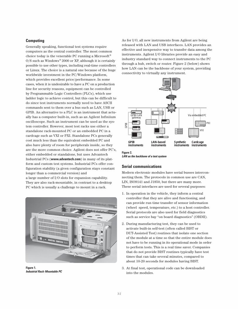
As for I/O, all new instruments from Agilent are beingreleased with LAN and USB interfaces. LAN provides aneffective and inexpensive way to transfer data among theinstruments. Agilent I/O libraries provide an easy andindustry standard way to connect instruments to the PCthrough a hub, switch or router. Figure 2 (below) showshow LAN can be the backbone of your system, providingconnectivity to virtually any instrument.
Serial communications
Modern electronic modules have serial busses intercon-necting them. The protocols in common use are CAN,LIN, ISO9141 and J1850, but there are many more. These serial interfaces are used for several purposes:
1. In operation in the vehicle, they inform a central controller that they are alive and functioning, and can provide run time transfer of sensor information(wheel speed, temperature, etc.) to a host controller.Serial protocols are also used for field diagnosticssuch as service bay “on board diagnostics” (OBDII).
2. During manufacturing test, they can be used to activate built-in self-test (often called BIST or DUT-Assisted Test) routines that isolate one section of the module at a time so that the entire module doesnot have to be running in its operational mode in orderto perform tests. This is a real time saver. Companiesthat do not provide BIST routines typically have testtimes that can take several minutes, compared toabout 10-20 seconds for modules having BIST.
3. At final test, operational code can be downloaded into the modules.
Figure 1.
Industrial Rack-Mountable PC
GPIBinstruments
GPIB/LANgateway
Via embedded PC
PXI
VXI
GPI
B
LAN-basedinstruments
Syntheticinstruments
Cardcageinstruments
LAN
Figure 2.
LAN as the backbone of a test system

3-3
Although Agilent does not currently offer serial commu-nications products, many small companies do offer goodsolutions. One such company is Engenius, of Livonia,Michigan. The Engenius Multicomm III/s has been usedin the Agilent TS-5400 Series II automotive functionaltest system for many years. There are also PCI plug-incards and other standalone boxes available. For additional information see www.EnGenius.com.
Low frequency stimulus instrumentation
In automotive electronics, it is often necessary to createmany dynamic (AC) waveforms and many static (DC)voltages at the same time, even when using BIST routines.For example, in a powertrain electronic module, it is nec-essary to generate Cam, Crank and Top-Dead-Center sig-nals which are phase locked, and a knock signal.Oxygen sensors, throttle position sensors and other sensors are often simulated with programmable DC voltages. Thus, several arbitrary waveform (Arb) channels and several D/A converter (DAC) channels arerequired. The 34980A can be used for these applications,thanks to its 34951A 4-channel isolated DAC card withdownloadable sequence memory, allowing it to be usedas both DACs and Arbs.
An Agilent tutorial series on the web shows how to down-load Cam/Crank/TDC waveforms to the 34951A 4-channelDAC card. See www.agilent.com/find/waveforms.
Low frequency measurement instrumentation
A 6.5-digit digital multimeter (DMM) is the most obviousmeasurement instrument needed by a test system. Notonly is it good for taking fast DC and AC voltage, currentand resistance measurements for testing the DUT, it alsoserves as a diagnostic tool to verify switch paths withinthe system. In most cases, a relatively inexpensive DMMsuch as the 34401A or the one that is built into the34980A is sufficient. However, it is wise to not rule outthe more expensive 8.5 digit 3458A if a digitizer is alsoneeded. The 3458A can be used as a digitizer for meas-urements up to about 100K Sa/s. As a dual-purposeinstrument (voltmeter and digitizer), it can save rackspace and cost over the use of standalone digitizers oroscilloscopes.
Testing of engine control modules typically requires themeasurement of inductive flyback from ignition coils(~450 volts) and fuel injectors (~80 volts). These are lowenergy voltage spikes, but the high voltages require somespecial care. Since 34980A relays can handle 300V withno problem, the 80 volt spikes from the fuel injectors areeasily measured. However, ignition coil flybacks requireattenuation before they can be measured. One good wayto do this is to add an attenuator to a system using the34980A breadboard card. A simple resistive divider canbe used, or a more exotic solution can be obtained byputting a dual-range attenuator on the card that attenu-ates voltages above say, 14V, and leaves them aloneunder 14V. In this way, you can get full accuracy on satu-ration voltages while still being able to measure the highvoltage flyback at somewhat reduced accuracy.
Figure 3.
Engenius Multicomm III/s (with box enclosure removed) with
personality modules to handle various serial protocols
DAC
Input
Dual slope attenuator
Voltages greater than V1 + Vd1 or less thanV2 - Vd2 are attenuated 20:1
Attenuated outputto high impedancedigitizer
R1
R2
D1
V1 V2
D2
10K190K
DAC
Figure 4.
Typical circuit for breadboard card to allow measurement of high voltage
flyback pulses from fuel injectors and ignition coils. The DACs can be
on-board voltage sources, or the 34951A card DACs can be routed
to the Breadboard card.

3-4
Load and measurement switching
Another facet of automotive electronic functional test isthe requirement to attach loads to the outputs in orderto simulate the loads found in a real automobile. Thesecan be light bulbs, solenoids, resistors, motors and evenother electronic modules. This means that a physicalspace needs to be created in the test system for mount-ing of such loads. This can be done in a number of ways.Card cages that are large enough to hold relays and loadscan be devised, as is done in the Agilent TS-5400 SeriesII test system’s “switch/load unit” (SLU). The SLU is a VME enclosure with a special backplane, andinterfaced to the PC via a parallel port. Special relaycards capable of handling the high load currents (2-30 Amps) were developed. In many cases, the requiredloads could be placed directly on these load cards. Thisbox also served as a place for instrument switching.Alternatively, loads can be mounted on a slide-out loadtray, with cables run to the switching system.
Today, with the Agilent 34980A switch/measure unit,much of the functionality previously done in the TS-5400’sSLU can now be moved into a standard product. The34980A can handle load currents up to 5A. Higher currentsdrawn by motors and light bulbs must still be handledexternally, however the 34980A offers the capability ofdriving such external relays via the breadboard card. Anumber of latching and non-latching armature relay cardsare available for the 34980A to handle load channels.
It is necessary in any test system to apply static anddynamic voltages and currents to various pins on thedevice under test (DUT) and then measure the response on other pins, usually with a DMM and an oscilloscope ordigitizer. In order to maximize the re-use potential of suchinstruments while keeping test system costs as low as possible, a matrix switching architecture is often used. Afull m x n matrix that would allow any point on the DUT to be connected to any system resource would be very largeand expensive. However, if BIST routines can be used toselect only certain sections of the module, an “m” x 8 x “n”matrix can be used, allowing 8 single-ended or 4 differen-tial measurements to be made at once.
Measurement and stimulus relays usually do not need to behigh current, and can thus be implemented with reedrelays or FETs, providing high speed switching which helpsto improve throughput, an important consideration in highvolume manufacturing test. Load relays typically requirearmature relays, which are by nature slow (on the order of10-20 ms to close and again to open). The 34980A providesall three types of relays in various configurations (generalpurpose, mux and matrix), providing maximum flexibility.
Power, loads
Connecting a device under test (DUT)
VBATT
"Load"(short)
"Load"(short)
Load
GND PS1
34980A21Inst.: 1DUT pin: 2 3 8
H L
L
H
L
H
L
H
L
H
L
H
L
H
L
H
L
H L H L H LCol 1 Col 2 Col 3 Col 8 Col 1 Col 2 Col 3 Col 8
Analog BusesABus 1DMM
(MEAS)
ABus 2DMM
(SENS)
ABus 3
ABus 4
3 8
Matrix 1 Matrix 2
H L
L
H
L
H
L
H
L
H
L
H
L
H
L
H
L
H L H L LH
ROW
COLUMN
Figure 5.
Typical load switching in an automotive electronic test system. Loads
can be physical parts such as light bulbs, resistors or motors as indi-
cated by the box in the center, or they can be simple wires ("shorts")
as shown at the top and bottom, which is a handy and consistent way
to connect power supplies to the DUT. The SPDT relays on the right
can be omitted if reverse polarity is not needed.
Figure 6.
"m" instruments x 4 2-wire busses x "n" DUT pins

3-5
DUT power
In a functional test system, the DUT must receive DCpower in order to operate. Often, this supply voltagemust be stepped to a number of different levels in orderto verify the electronic module’s response to low or highbattery conditions. In a test system, these steps need toexecute quickly so that power supply settling time doesnot become a bottleneck. It is also sometimes desirableto provide a second supply dedicated to the loads. Other voltages are needed occasionally for line automa-tion control. A good system component, then, must be a small, multi-output programmable supply that canrespond to commands quickly and that has outputs that can change quickly. The N6700A power supply fills these requirements admirably.
Mass interconnect
Getting the system resources out to the DUT in a way that allows changeover from one DUT to anotherrequires a mass interconnect scheme. This is best implemented using either Mac Panel or Virginia Panelstandard connection schemes. Virginia Panel offers a set of pre-assembled cables that can be used to connect the 34980A to their terminal blocks. Seewww.vpc.com/agilent/ for details.
Figure 7.
The N6700 is an excellent choice for a multi-output programmable
DUT power supply
Figure 8.
Virginia Panel web page1
1Used with permission, Virginia Panel Corp. All legal and privacy restrictions apply. See http://www.vpc.com/privacy_statement.htm
Parameter Agilent N6700A/N6752A Typical system DC sources
Command < 1 ms 20 to 50 msProcessing Time
Output < 4 ms to 50 mV 50 to 500 ms to <1%Response Time

3-6
Putting it all together
Figure 9 shows an example of a test system architecturethat can be used for many automotive electronic modules.The matrix switch allows many measurement devices to be connected to the DUT via the 34980A’s 4-wire differential bus. The armature switches are used forloads, and the isolated DAC cards are used for DC andAC stimulus. The N6700 power supply is used to provideDUT power. In this way, the 34980A forms the core of thesystem. An external PC would be used to control alldevices using LAN. A 3rd party serial communicationsinterface would be used to provide CAN or other serialcommunications to the DUT. All wires leading to theDUT would pass through a fixture interface such as a Mac or Virginia Panel (not shown for clarity).
CAN
Engine control moduleconnected to test system
DA converters
ECM
Function generators
Resistors mountedon load tray
34951A
34937A34937A
34937A
34937A
(34980A DMM connected internally �to Bus 1 and 2)
1
2 Oxygen Injector 1
Throttle pos Injector 2
Prndl 0
Prndl 1
Prndl 2
A/C on
Cam
Crank
TDC
Knock
CanL
CanH Gnd
Check Eng
Ignition
Massair flow Injector 3
Watertemp Injector 4
3
4
5
6
7
8
9
10
11
12
13
14 15 16
17
18
19
21
22
20
VBatt
34951A
N6700 system P/S
Mounted on load trayMounted on load tray
34959A
34933A
Signalconditioning
Bus
1
High
Low
Inst
1In
st 2
Inst
3In
st 4
Inst
5In
st 6
Inst
7In
st 8
2
3
4
34933A34933A
Figure 9.
Typical design of an automotive electronic functional test system.
In this example, only one 4x8 bank of relays was shown on the
34933A matrix. Add more banks and more cards to be able to connect
to more DUT pins or more instruments. "Inst1-8" can be external
instruments or cards internal to the 34980A, such as the
counter/timers.

Agilent Technologies TS-5400Series II Automotive ElectronicsFunctional Test System
Antilock brake system/traction
control electronic control
module testing
Smarter cars are here; they warm your
seats, set your radio station, tell you
where to turn next and drive over icy
patches and wet roads. The latter of
these features is of particular concern for
most drivers weathering the changing
seasons and terrain of their everyday
driving route. Antilock brake and traction
control systems (ABS/TC) are considered
necessary car safety features today. As a
result, ABS/TC electronic control module
(ECM) manufacturers are pressured to
make safer, more reliable systems. For
this reason, functional testing of ABS/TC
ECMs becomes paramount and extensive
monitoring of the system components is
done in its normal course of operation.
ABS/TC ECM functionality relies on
variable reluctance sensors (VRS), sole-
noids, pump motors and fail lamp outputs,
which all have “recapture” monitor lines
that allow it to determine the state of
each input/output. What follows is a
sampling of manufacturing functional
tests on the ABS/TC ECM that lend
to increased reliability and system
integrity using the Agilent Technologies
TS-5400 Series II electronics functional
test platform.
Serial Link
The backbone of UUT-assisted testing
(manipulation and verification of ECM
functionality via the serial link) lies in the
ability of the ECM to communicate with
the test and measurement instrumenta-
tion. The common serial interfaces include
UART-based ISO-9141, J1850 (pulse width
modulated and variable pulse width), and
J1939 (controller area network).
I/O Check
An input/output check may be easily
accomplished by verifying that the ECM
correctly reads the states of a given input
or output.
Testing
Typically, the ECM designer determines
the algorithm for setting the module in
either a TEST or RUN mode. This algo-
rithm, a specific handshake for example,
is often executed in a given window of
time just after the system is powered
up (~500 ms for example), which is
determined by the serial interface
chosen. Therefore, testing the serial
communication of the ECM can be
accomplished using one of several
methodologiesbased on specific
ECM design.
Agilent TS-5400 Series II testing solution
In an effort to meet the needs of the most
common serial interfaces, this system
features an optional serial port adapter
that supports ISO-9141, J1850, and J1939
serial communication. In addition, the
Test Executive software provided with
the platform has built-in action sets to
facilitate serial communication to set
the ECM in either test or run mode.
The software envelope supporting this
hardware feature set includes easy-to-use
commands for test plan development.
A few Agilent TestExec SL actions related
to serial port communication follow.
Aside from the expected Read/Write/
Configure software capabilities for
serial communication provided, the
test executive streamlines common
process steps used in ECM functional
testing. For example, sending the ECM a
periodic “keep alive” message (referred
to as a group message below) to maintain
TEST mode (rather than RUN mode) is
made significantly easier with the
following actions:
mComConfigGroup: Configures any of
the support serial interfaces for a
group message
mComStartGroup: Specifies the time
between groups, between group elements,
group repeat count and the group
message itself. GroupRepeatCount = 0
represents indefinite repetition of a keep
alive message
Testing Antilock Brakes and TractionControl with the Agilent TS-5000Family of Automotive ElectronicsFunctional Test Systems
Application Note
4

4-2
Variable Reluctance Sensors
A variable reluctance sensor (VRS) at each
wheel provides wheel speed signals to
four receivers located in the ECM.
Occasionally, the rear wheels share a
sensor, but this is seen less frequently
in the industry today. The frequency
generated by these sensors is directly
proportional to velocity. Voltage levels on
each VRS may range from 50 mVpp (at 20
Hz) to 200 Vpp (at 5000 Hz).
Wheel slippage detection
Since the frequency generated by the
signals is proportional to velocity,
frequency changes relative to each of
the sensors indicate that slippage on
one or more of the wheels have occurred.
It is paramount, therefore, that the test
platform provides up to four independent,
isolated frequency signals if all four
wheels are to be simulated at once.
Additionally, these signals need to
sweep along different ramp profiles,
which traditional frequency generators
are incapable of doing.
Testing
Three of the wheel sensor inputs are
routed to three wheel inputs and are
held at constant amplitude and frequency
representing constant velocity (1Vpp at
1kHz for example). The fourth wheel
sensor input is applied with a swept
waveform in both an upward and
downward ramp; see Figure 1. The
test verifies that at a certain frequency
difference between the wheels, or at a
certain change in frequency for a given
wheel, the correct isolation or purge
solenoids are activated.
Agilent TS-5400 Series II testing solution
This system can be configured to include
the E6173A arbitrary waveform generator
for use in this test. Ramp times can be
programmed with the E6173A ARB to be
symmetric or asymmetric, depending on
the desired input. Frequency generators
cannot provide this type of complex swept
waveform. The platform’s software
includes built-in actions allowing ease of
programming for ramp up times, duration
and ramp down times. The E6173A has
two isolated channels. Therefore, if
simulation of four simultaneous wheel
speeds is desired, using two generators
is advised.
Supporting this hardware solution is the
test executive software envelope with
action routines and test plan examples
for the E6173A arbitrary waveform
generator.
A sampling of TestExec SL actions for the
E6173A ARB include the following:
arbConfOut: Configures the ARB’s
output circuitry
arbSet: Programs the ARB by
transferring all settings specified
in the configuration
Arb_Dl_Swept_: Downloads a basic
swept waveform of specified
frequency, amplitude and offset
Arb_Dl_Std_Waveform: Downloads
a sine, square/ pulse, or triangle
waveform of a specified frequency,
amplitude, and offset.
Arb_Dl_Custom_Waveform:
Downloads a custom, user-defined
waveform consisting of up to ten
sequences with fifty segments per
sequence to the ARB.
Cross Talk
Testing the ABS/TC module’s handling of
cross talk is important when assessing
the system’s ability to properly interpret
the incoming VRS wheel signals.
Misinterpretation due to channel-to-
channel cross talk may cause the
system to react incorrectly.
Testing
One channel is set to high voltage AC and
the others are set to either low-level AC
values (less than 100 mV) or to DC. If
cross talk due to the high-input voltage
channel exists, the low-level channels will
respond, despite the fact that their own
voltage levels do not warrant action.
Speed status is requested via the serial
link and no speed should be present on the
non-driven inputs.
Figure 1: Swept waveform for fourth wheel sensor input (other three held constant)
400Hz
150Hz
Freq
uen
cy
Time (ms)
0 100 150 200 250 300 350 400 450 500 550

4-3
Wheel Speed Threshold
The required response of the VRS receiver
located at the ECM is illustrated in Figure
2. Verifying this expected behavior requires
testing at multiple frequencies to
characterize the wheel speed threshold.
Testing
This test would require the ability to
apply various discrete input voltage and
frequency values. The test might include
input frequencies of 18 Hz, 400 Hz, and
1800 Hz at voltage levels just above and
below the threshold at each frequency.
Agilent TS-5400 Series II testing solution
To perform the cross talk test, the E6173A
Arbitrary Waveform Generator will
generate up to 32 Vpp, requiring a step-up
transformer in order to generate the
required testing voltage levels. The
optional E6171B Measurement Control
Module (MCM) has an on-board
transformer that can deliver 160 Vpp.
When testing the wheel speed threshold,
the generated waveform does not require
additional signal processing since the
stimulus is no more than 2 to 3 volts for
high-frequency testing. In both tests,
the system supports common serial
communication, including ISO–9141,
J1850, and CAN/J1939 for response
verification from the ECM.
Short/open sensor
In the vehicle, the ECM monitors shorts
and opens on the VRS sensors. A VRS
sensor includes a ferromagnetic disk
and sensing coil. This sensor may be
represented in an overall circuit as a 1.5kΩ
resistor in series with an AC voltage
source. The ECM passes current through
the sensor, which should be floating with
respect to chassis for noise rejection.
Therefore, monitoring the sensors for
shorts or opens becomes crucial to
maintaining system integrity. The
sensors may be compromised, for
example, when salt deposits cause
leakage current to pass from the sensor to
chassis ground. This results in decreased
noise rejection, which leads
to improper event determination by the
ECM. Similarly, if the sensor were opened,
current would not pass and event determi-
nation would once again be inaccurate.
Testing
In the vehicle, the ECM monitors the
shorts and opens. In production testing,
the VRS open, short, and short-to-chassis
detection feature is accomplished via relay-
induced faults. The fault is verified by
interrogating the ECM via the serial link
and/or by the ECM turning on the
display failure lamp.
Agilent TS-5400 Series II testing solution
This test system can be configured to
include several different load cards for this
application. In particular, E6175A 8-
Channel Load Card, E6176A 16-Channel
Load Card, and the E6177A 24-Channel
Load Card would be appropriate choices.
Since VRS testing involves current levels
no greater than a few milliamps, users
typically select the E6177A 24-Channel
Load Card due to its bridge load
capabilities. Serial communication with
the ECM may be accomplished via one of
the common interfaces supported by the
platform: ISO-9141, J1850, or J1939.
The test executive software supports the
comprehensive signal and load routing
architecture. The TestExec SL switch
path editor provides a less cryptic, easily
read path description. In addition, for test
plans where relay actions are repeated
in various sections, relay state tracking
streamlines redundant commands by
recognizing the existing state of the relay,
thereby speeding the time of test.
Figure 2: ABS/TC ECM response to VRS input
20Hz 500Hz 2000Hz
Region where there
is a signal that the
ECM must recognize
3V
mV
Region where
there is noise
that the ECM
must reject
4-4
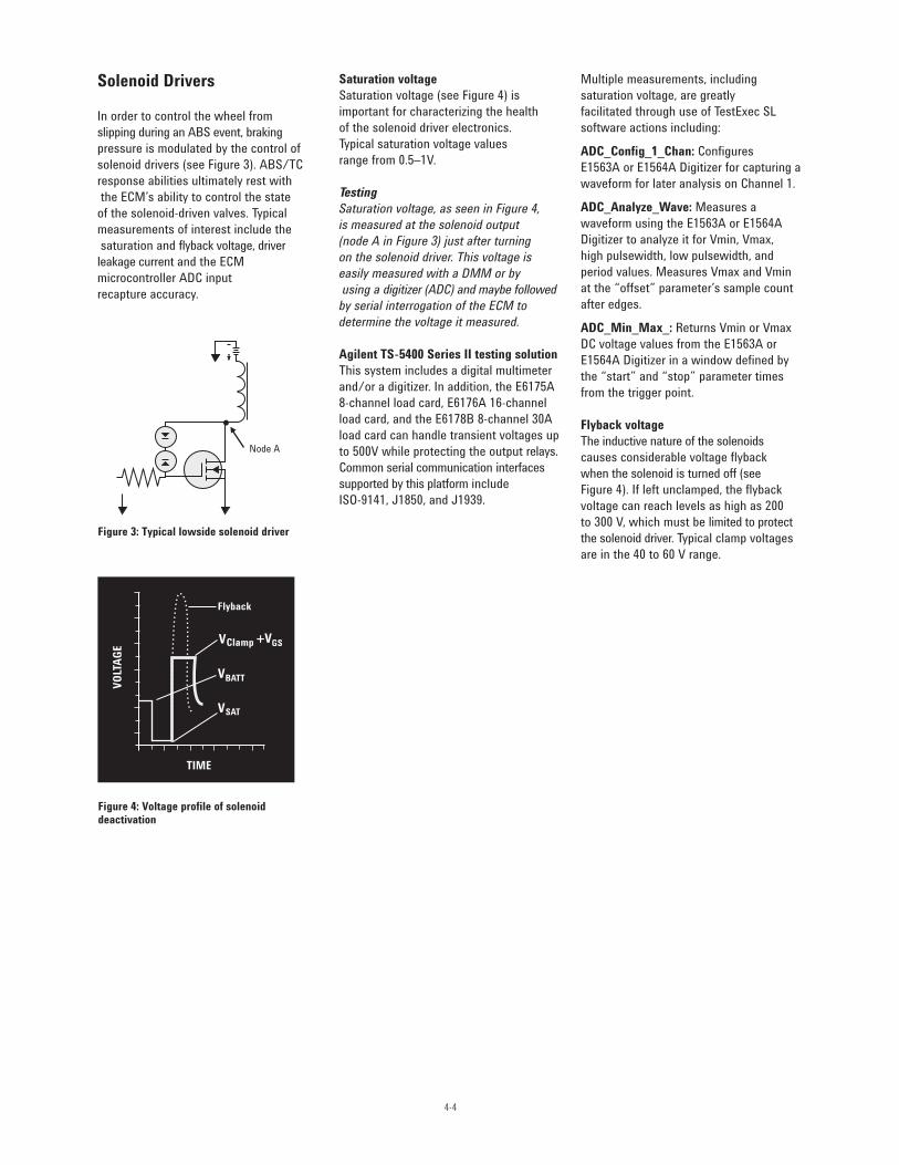
Solenoid Drivers
In order to control the wheel from
slipping during an ABS event, braking
pressure is modulated by the control of
solenoid drivers (see Figure 3). ABS/TC
response abilities ultimately rest with
the ECM’s ability to control the state
of the solenoid-driven valves. Typical
measurements of interest include the
saturation and flyback voltage, driver
leakage current and the ECM
microcontroller ADC input
recapture accuracy.
Saturation voltage
Saturation voltage (see Figure 4) is
important for characterizing the health
of the solenoid driver electronics.
Typical saturation voltage values
range from 0.5–1V.
Testing
Saturation voltage, as seen in Figure 4,
is measured at the solenoid output
(node A in Figure 3) just after turning
on the solenoid driver. This voltage is
easily measured with a DMM or by
using a digitizer (ADC) and maybe followed
by serial interrogation of the ECM to
determine the voltage it measured.
Agilent TS-5400 Series II testing solution
This system includes a digital multimeter
and/or a digitizer. In addition, the E6175A
8-channel load card, E6176A 16-channel
load card, and the E6178B 8-channel 30A
load card can handle transient voltages up
to 500V while protecting the output relays.
Common serial communication interfaces
supported by this platform include
ISO-9141, J1850, and J1939.
Multiple measurements, including
saturation voltage, are greatly
facilitated through use of TestExec SL
software actions including:
ADC_Config_1_Chan: Configures
E1563A or E1564A Digitizer for capturing a
waveform for later analysis on Channel 1.
ADC_Analyze_Wave: Measures a
waveform using the E1563A or E1564A
Digitizer to analyze it for Vmin, Vmax,
high pulsewidth, low pulsewidth, and
period values. Measures Vmax and Vmin
at the “offset” parameter’s sample count
after edges.
ADC_Min_Max_: Returns Vmin or Vmax
DC voltage values from the E1563A or
E1564A Digitizer in a window defined by
the “start” and “stop” parameter times
from the trigger point.
Flyback voltage
The inductive nature of the solenoids
causes considerable voltage flyback
when the solenoid is turned off (see
Figure 4). If left unclamped, the flyback
voltage can reach levels as high as 200
to 300 V, which must be limited to protect
the solenoid driver. Typical clamp voltages
are in the 40 to 60 V range.
Figure 3: Typical lowside solenoid driver
Figure 4: Voltage profile of solenoiddeactivation
Node A

4-5
Testing
There are two readily recognized ways to
test flyback voltage: a static measurement
that uses a voltage source and resistor
(see Figure 5) and a dynamic measurement
with the solenoid load in place. The
dynamic test is often considered a more
credible method of test. In the case of the
static measurement, a voltage source
of ~100 V and a resistor of ~10 kΩ may
be used. The voltage is applied and the
output, Vout, is measured to verify that the
protective clamping circuit on the solenoid
driver is functioning correctly (see Figure 5).
In dynamic testing, an Analog to digital
converter (ADC) may be used to process
the signal for use by the ECM microcon-
troller. The benefit of dynamic testing lies
in its ability to capture multiple character-
istics of solenoid driver behavior in a sin-
gle test, such as saturation and flyback
voltage. Typically, capturing the saturation
and flyback voltage simultaneously is diffi-
cult because the first is 0.5 to 1V, while
the latter may be several hundred volts.
The disparity in these voltage levels
prohibits good resolution of their values.
However, by employing a dual slope
attenuator, high voltages are attenuated
within a range that captures both
(saturation and flyback) to be captured
with good resolution. Figure 6 illustrates
a typical voltage profile resulting from
a dual slope attenuator.
Agilent TS-5400 Series II testing solution
For static testing of the flyback voltage,
the platform’s E6171B measurement
control module (MCM) can be programmed
to apply a 100 V-compliance voltage with a
current source limit of 1 mA. The output
is then measured with a DMM to verify
clamping levels of 40 to 60V. The TestExec
SL software support for these actions
include the following:
ForceVMeasI: MCM used as voltage
source then measures the current flow
using the DMM
In addition, the following parameters will
define the test and qualify its results:
Vapply: Applied DC voltage
Iexpect: Expected current (milliamps)
Iactual: Actual current (milliamps)
read by the DMM
For dynamic testing of flyback voltage,
the system may be configured to include
a digitizer (ADC) to simplify the test. Once
the solenoid driver is turned on and off,
the resulting output voltage waveform is
captured and saved to a waveform data
type file using built-in software actions.
The MCM’s onboard, programmable dual
slope attenuator can be set to scale high
input voltage values as desired.
Next, a comprehensive list of information
may be extracted from the waveform,
including flyback and saturation voltage,
solenoid driver on/off time and duration of
the flyback pulse. Using this platform with
the optional digitizer allows this extensive
data set to be acquired in just one setup.
Software support for this sophisticated
test methodology includes the following
TestExec SL action:
ADC_Transform: Transform E1563A
or E1564A digitizer returned data with the
MCM attenuator gain and offset terms.
This action converts digitizer readings
through the attenuator to the values at
the input of the attenuator.
Parameters to define the test action and
qualify the results are as follows:
trigfirst: 1=Reads data from digitizer
before running analysis routines
atten: Configures the attenuator;
1 = adjust for MCM attenuator,
0 = do not adjust
store: 1 = Write to file, 0 = Do not
write to file
Figure 5: Static measurement of flyback voltage Figure 6: Input-output voltage profile of dual-slope attenuator
Vout
To µControllerin ECM
10 kΩ
DriverFET
VsrcVout Attenuation of output:
Ratio 20:1
1:1 Input-output ratio
Vin-Vth Vth

4-6
Driver leakage current
Information on the driver leakage current
verifies the health of the driver FET (see
Figure 3). Excessive leakage current is
indicative of possible electrostatic
damage (ESD).
Testing
To measure driver leakage current,
disconnect the load and measure the
current flowing to the solenoid driver
while it is in the “off” state at node A
in Figure 3.
ECM microcontroller (µC) ADC
recapture accuracy
When the solenoid driver initiates, the µC
ADC input must accurately capture the
“on” voltage level and likewise, when the
driver turns off, it must accurately capture
the resting voltage level to determine the
condition of the driver and solenoid load.
Ultimately, in order for the ABS/TC ECM
to behave appropriately and run its own
self-diagnostics of the output solenoid,
the µC ADC recapture must be accurate.
For example, during operation of the
vehicle, a test pulse is continuously
generated every few milliseconds with a
short duration of ~300 µs such that the
driver is not activated (see Figure 7).
Testing
Disconnect the solenoid load and apply
a DC voltage supply to turn on the driver.
Determine the voltage value seen by the
µC ADC recapture path by serial interrogation
of the ECM. The voltage seen at the input
to the µC should reflect the applied
voltage giving consideration to the
circuit design of the recapture path.
Agilent TS-5400 Series II testing solution
The platform’s MCM contains a VI
function that applies a low fixed voltage
and measures the resulting current.
This functionality greatly simplifies the
solenoid driver’s leakage current
measurement.
The TestExec SL software support for this
action includes the following:
ForceVMeasI: MCM used as voltage
source then measures the current flow
using the DMM
For testing the µC ADC recapture
accuracy, the MCM can be used as a
dc source voltage to the solenoid driver.
Through serial interrogation, several
sections of the resulting voltage profile
may be tested for accuracy. Generally, the
“on” voltage of a few hundred millivolts,
the resting voltage of Vbatt and one
other voltage level are used for
verification. Serial communication
with the ECM may be tested on any of the
supported common interfaces: ISO-9141,
J1850, or J1939.
Smart Drivers
Today, ABS/TC systems often employ
smart drivers that sense the condition of
the solenoid and turn themselves off if the
situation warrants, such as a short on the
solenoid load.
Testing
Verifying that the smart driver responds
appropriately to a short detection may
require analog to digital conversion.
Two facts should be verified: (1) the µC
registers an over current condition when
the solenoid load is shorted; (2) the smart
driver reacted appropriately by shutting
down to prevent damage. Verifying these
facts requires knowledge of the peak and
duration of the solenoid current profile, as
seen in Figure 8. Finally, interrogation via
the serial link will determine if the ECM
was informed of an over current condition.
Figure 7: Test pulses applied regularly as a diagnostic input for determin-ing ABS system integrity
Figure 8: Solenoid current profile with working smart driver when load is shorted
Flyback
Solenoid off
Solenoid
on
Test
pulse
~300 µs
Test
pulse
~300 µs
-50 volts
V batt
0 volts
~5 microseconds Time (microseconds)
Curr
ent
(Am
ps)
flow
ing
into
Node
"A
" (s
ee fi
gure
3)
20
0

4-7
Agilent TS-5400 Series II testing solution
Using TestExec SL, this waveform may
be saved with the needed characteristics,
such as peak and duration of the solenoid
current extracted from the results. In
addition, if the driver fails to shut down,
protective fuses are built-in to several of
the load cards.
Relay induced faults, such as a short
across the solenoid load, can be created
with the available load card switching for
this platform. Load cards featuring 50 mΩ-
sense resistors for current sensing should
be placed in series with the shorted
solenoid load. Then, the voltage drop
across the resistor can be measured by
use of a digitizer or digital multimeter
(also configurable with the platform). The
results will determine if the driver shut
down when the over current condition
was induced.
The E6178B 8-channel heavy duty load
card is typically selected for its high
current capabilities. Other load cards are
generally equipped with fuses to protect
the card in the event of prolonged, high
current applications. This test could
potentially result in a prolonged high
current scenario if the smart driver fails.
Serial interrogation via any one of the
supported interfaces, including ISO-9141,
J1850, and J1939, will verify that the
ECM was prompted with an over
current condition.
Pump Motor Driver
Since hydraulic fluid is diverted to the
dump accumulator during an ABS event,
the fluid must be returned to the master
cylinder/high pressure side of the
hydraulic system. After each DUMP cycle,
the pump motor is used to recycle
hydraulic fluid to the high side of the ISO
valve. The pump motor requires significant
current with start-up surge currents as
high as 200 Amps (for ~20 ms) and steady
state currents of 10 to 30 Amps.
Testing
Testing the pump motor drivers closely
resembles the previously outlined
algorithms for testing solenoid drivers.
The distinguishing characteristic of pump
motor driver testing is the potentially high
current levels the test and measurement
instrumentation must tolerate.
Agilent TS-5400 Series II testing solution
The load card switching capability
of the E6178B 8-channel heavy-duty load
card option with this platform has the
current ratings to effectively test the pump
motor driver despite the increased current
levels. In addition, the loads are protected
with 30 A fuses in the event that the pump
motor driver fails to shut down.
Antilock Brake System Test Solution
Optional throughput multiplier
The Agilent TS-5400 Series II automotive
electronics functional test system may
be configured to include an optional
throughput multiplier, which is often used
when testing low pin-count/complexity
ECMs. The throughput multipler facilitates
multiple up UUT (unit under test) testing.
Multiple up UUT testing results in decreased
set up time of the instrumentation per
UUT, consolidating delays in relay closures
and overlapping time delays due to inherent
UUT latencies. The TestExec SL software
tool provides comprehensive support for
this test strategy.
Automotive electronics manufacturing
environment
The TS-5400 family of automotive
electronics functional test systems offers
support for factory automation. From a
more basic automation scheme to the use
of PLC (programmable logic controllers),
the TS-5400 Series II has comprehensive
serial communication support and digital
I/O capabilities allow the platform to be
integrated as part of an existing
manufacturing environment.
Overall solution
The test needs for antilock brake system
ECMs as generally outlined in this
application note may be satisfied by
the following instrumentation.*
• Arbitrary waveform generator
• Digitizer
• Digital multimeter
• Serial port adapter
• Power supply
• Measurement control module
• Select load cards
*Note: This instrumentation list is presented asa general test solution profile, and is not for useas a direct ordering guide. For information onthe detailed platform profile, please refer to theProduct Note.
ReferencesJurgen, Ronald. Automotive Electronics Handbook. McGraw Hill Inc, 1999. Mizutani, Shuji. Car Electronics. Sankaido Co,Ltd., 1992.

4-8

Agilent Technologies TS-5400 Series II and TS-5020Automotive ElectronicsFunctional Test Systems
Security and safety: testing
remote keyless entry and
immobilizer functionality
Security and safety go hand-in-handin the world of automotive technology.Whether you are testing remote key-less entry (RKE) or immobilizersthat provide protection from vehicletheft, the Agilent TS-5400 Series IIand TS-5020 automotive electronics functional test systems are preparedwith test solutions.
As the need continues to increase forluxury technology, automotive RKEsystems are equipped with everythingfrom door or trunk release to moresophisticated functions includingstarting the engine, setting a radiostation, positioning seats, and adjust-ing mirrors. In addition, many RKE
systems are equipped with other features that include interior lightactivation, system disarmament, orautomatic panic alert.
Typically, RKE functionality isembedded in the body control module(BCM) that controls electromechani-cal drivers for door locks, windshieldwipers, interior lighting, and othersuch functionality. Developing a dedicated electronic control module(ECM) for RKE functionality is alsoan option. Figure 1 illustrates thecomponents of a generic BCM withRKE functionality. In addition, theadvent of RKE works in conjunctionwith the need for increased securityin cars and the emergence of immo-bilizers.
What follows is a sampling of manu-facturing functional tests that leadto increased reliability, security, andsystem integrity using the TS-5400Series II and TS-5020 test systemsfor RKE and immobilizers.
The electronics behind RKE func-tionality lies in translating codedinput from a key fob into commandsfor electromechanical drivers locatedthroughout various parts of the car.In general, activity (as seen in Figure2) includes code generation by ahand-held key fob, signal detectionand processing, followed by authen-tication code verification. Finally,the electronic control module generates a serial command or direct output to a variety of drivers(door locks, seat positioning motorand more.)
Testing Remote Keyless Entry Systemswith the Agilent TS-5000 Family ofAutomotive Electronics Functional Test Systems
Application Note
Power
Inputs
(serial, analog, digital)
Driver outputs
(solenoids, motors,lights, alarm, etc.)
Audible outputs
Messaging
Immobilizer
RKE
Figure 1: Body control module (with remote keyless entry & immobilizer)
16-32 bit code from remote
RF generator/modulator
Key
fob
Wit
hin
veh
icleECM (BCM)
Receiver
Drivers
Carrier and signal
Figure 2: RKE functionality action flow
µController
5

5-2
Transmitter
In Figure 2, the key remote (trans-mitter) includes an identificationsignal generating integrated circuitand is powered by a small battery.The identification signal is typicallya 32 to 64 bit rolling code, whichrequires some form of modulation in subsequent signal processing.Issues of security and sensitivityregarding the algorithm for generatingthis code render it a customer pro-prietary test section, oftenrequiringtreatment as a "black box." In thiscase, the customer generally suppliesthe code for the transmitter in theform of a working key fob or modula-tion device. Since RKE transmittersare inactive virtually 99% of the time,low power modes are important. Inits inactive mode an RKE transmittercurrent of 100 nA is generally accept-ed with a current draw of 10 to 12 mAfor active RF transmissions.
Testing
Though not always performed, testing the RF power output of thekey fob may be of interest.
Testing may involve checking thesignal strength of the key fob outputamplitude and center frequencywhen it enters a particular mode.For example, following a certainkeypad command the key fob mayenter a continuous wave mode thatgenerates a non-modulated RF out-put. Other test modes may includegeneration of an AM or FM output.When testing, a known working key fob maybe used to calibrate thetester, while subsequent testing iscompleted based on relative signalstrength analysis. In conductingthese tests, specific spectrum ana-lyzers may be selected from themarket.
Agilent TS-5400 Series II and TS-5020
testing solutions
Any of the Agilent ESA Series RFspectrum analyzers will meet thespecifications needed for key fobpower analysis. The test executive(TxSL) has several post-process data extraction, analysis and displaycapabilities for output amplitudeand center frequency determination.The select data may be extracted and presented in a variety of formatsincluding database entries, wave-forms, arrays, etc., with associatedunits for easy-to-read reporting.
Testing
The transmitter is powered by alithium coin cell battery. Typically,the battery life is expected to be > 5 years at 25 °C. To promote thelifetime of the battery, verificationof leakage current during active RF transmission may be required.
Agilent TS-5400 Series II and TS-5020
testing solutions
These test systems may be configuredto include a measurement controlmodule (MCM). A built-in feature ofthe MCM includes the ability to pro-vide a voltage or current source andmeasure the output current or voltage,respectively. Therefore, using theMCM as a voltage source, the outputleakage current from the transmittermay be obtained.
RF Generator
The RF generator modulates the carrier code creating an output forthe RKE receiver. RKE RF bands are typically 315MHz in the UnitedStates and Japan or 434/868 MHz in Europe. Many current systemsemploy amplitude shift key modula-tion (ASK) as ASK-modulated data is easily created with surface acousticwave (SAW) transmitters. However,frequency shift key (FSK) modulationis developing a wider following as a result of stable and accurate fre-quency shifting at higher data rates.Specifications for the generator aredetermined by customer need andmay be selected from a variety ofproducts in the market.
Receiver and Drivers
An antenna with low voltage andcurrent ratings receives input fromthe RF modulator. The receivershould operate on a 9 to 16 V car battery. The receiver detects a validtransmission (message authenticationcode or MAC) from the key fob trans-mitter, which includes the transmitterID, rolling count, command code andstatus flags. To validate the MAC, the receiver compares its rollingcount with the transmitter ID rollingcount. The transmitter ID rollingcount is stored in the receiver’s non-volatile memory. For validity, thetransmitted rolling count should begreater than or equal to the receiverstored count within a given count"window." If the rolling counts do notmatch within this window, the receiv-er may initiate a resynchronization. If the rolling counts match, the ECMgenerates a serial command to thedrivers controlling door locks, interiorlights, alarms and more.

5-3
Testing
As a general practice, there are twoways of verifying RKE functionali-ty. Since RKE ECM test developersare not privy to the details of therolling code, one way is to verify theserial command generation by theECM and the second is by observa-tion of the electromechanical driverresponse to a given input com-mand. Each component of RKEfunctionality (seat positioning,interior lighting, panic alert, trunkrelease, etc.) may be tested this wayby sending a transmitter commandand verifying action via the serial link or through the relevant driverresponse.
Agilent TS-5400 Series II and TS-5020
testing solutions
These test systems can be configuredto include a custom card for mount-ing the key fob/black box providedby the customer directly on thetester. The RF signal source is typi-cally chosen between the N5182A and the E4438C signal generators for their bandwidth and modulationcapabilities. Serial communicationsupported by the platform includescommon interfaces such as ISO-9141, J1850 and CAN/J1939. AgilentTestExec SL includes support foreasy integration of message-basedinstrumentation. By following thewell documented instrument inte-gration procedure in TestExec SL, auser familiar with the message-basedinstrument and its desired parame-ters can establish integration andcomprehensive action definitions inunder thirty minutes.
A few TestExec SL actions related to serial port communication follow.Aside from the expected Read/Write/Configure software capabili-ties for serial communication provid-ed, the test executive streamlines common process steps used in ECMfunctional testing. For example,sending the ECM a periodic "keepalive" message (referred to as agroup message below) to maintainTEST mode (rather than RUN mode)is made significantly easier with thefollowing actions:
mComConfigGroup: Configures any ofthe support serial interfaces for agroup message.
mComStartGroup: Specifies the timebetween groups, between group elements, group repeat count andthe group message itself.GroupRepeatCount = 0 representsindefinite repetition of a keep alivemessage.
Response Time
To gain appeal as a luxury commodity,the consumer-based success of RKEtechnology lies in the system’s abili-ty to respond quickly to the user’spress of the keypad.
Testing
Normally, the elapsed time betweenpressing the RKE keypad and message generation should be < 300 ms. Therefore, determiningthe time to transmit, verify the code and generate a message is ofutmost importance, and is meas-ured in addition to the total time(including driver execution) of thesystem function (< 1 s).
Agilent TS-5400 Series II and TS-5020
testing solutions
A counter, such as the AgilentE1333A 3-Channel UniversalCounter, may be used to measure the time difference between pressingthe key fob and the resulting action(either code verification or totaltime). Supporting this hardwaresolution is the test executive soft-ware envelope with action routinesfor the E1333A Counter.
A sampling of the Agilent TestExecSL actions for the E1333A Counterinclude the following:
ctrConfTrigIn: Sets the input trigger.
trigfirst: Parameter used for triggerusage before reading. 0 for no, 1 foryes.
ctrIsSet: Waits until the Counter isready for measurement (returns truewhen ready).
ctrInitiate: Starts the previously configured Counter measurement.
ctrGetResults: Reads the Counter results.

5-4
Immobilizers Protect Against Theft
As mentioned above, the advent ofRKE is coupled with the need forincreased security in cars and theemergence of immobilizers to protectthem from theft. As the cost andcomplexity of the average car rises,so too does the need for greatersecurity to protect it from theft. Carmanufacturers as well as insurancecompanies are raising the standardfeatures on cars. As a result, theindustry is moving towards wideruse of immobilizers and basic securitysystems.
Whereas RKE systems provideremote control convenience andvehicle entry security, immobilizersprovide protection against vehicletheft. When an improper key is usedin the ignition, immobilizers turn off the starter circuit so the enginewill not engage.
Immobilizers are composed of a magnetic coil wound around theignition, a charge and detect module(transceiver) in the ECM, as well as a remote key fob equipped with a transponder. As the action flow in Figure 3 illustrates, immobilizerfunctionality lies in the signal com-munication between the transponderand charge/detect module of theECM so the system can determinewhether or not to start the engine. In most cases, immobilizer function-ality is part of the BCM while dedicated immobilizer ECMs areuncommon.
Radio frequency identification (RFID)
transponder
The key fob contains a transponderintegrated circuit. When the key isplaced in the ignition, the integratedcircuit induces a current in the mag-netic coil surrounding it, therebyexciting the coil, which feeds into atuned circuit. Once the charge cycle(burst of RF energy) is initiated bythe transceiver, the transponder isprompted to transmit its modulatedauthentication message. This messageprompt comes in response to a 120to 250 ms break in the transceivercharge cycle. The transponderresponse is generally characterizedas AM or FM modulated in non-returnto zero (NRZ) mode with duration of < 20 ms.
As in the case of the remote keylessentry key fob, this section of test iscustomer proprietary and is suppliedas either a working fob or black box.Unlike RKE, however, the code is notrolling code. Rather, it is fixed sincethis communication is not susceptibleto code grabbing techniques of thieves.
Testing
Improper orientation of the trans-ponder IC in the key fob, 180˚ rotation for example, will result in a lower level amplitude outputfrom the transmitter. In this case,orientation should be verified bygenerating the charge cycle andmonitoring the transponder IC"word" response amplitude.
Agilent TS-5400 Series II and TS-5020
testing solutions
Simulation of the charge cycle maybe achieved in two ways: Using theblack box or key fob given by the cus-tomer as a stimulus; or by emulatingthe cycle with the automotive-tunedAgilent E6173A arbitrary functiongenerator (a component that can beconfigured into the test platform).
The test executive software envelopewith action routines and test planexamples for the E6173A ArbitraryFunction Generator (VXI) or the33120 (GPIB) supports this hard-ware solution.
A sampling of the TestExec SL actionsfor the E6173A ARB include the following:
arbConfOut: Configures the ARB’soutput circuitry.
arbSet: Programs the arb by transfer-ring all arb settings specified in theconfiguration.
Arb_Dl_Std_Waveform: Downloads a sine, square/pulse or triangle waveform of a specified frequency,amplitude and offset.
Arb_Dl_Custom_Waveform:
Downloads a custom, user-defined waveform consisting of up to 10sequences with 50 segments per sequence to the Arb.
arbConfTrigIn: Sets input triggering parameters.
arbConfTrigOut: Sets output triggeringparameters.
arbInitiate: Starts the arb sequencerto output the waveform.
arbStop: Stops waveform output atend of current sequence on a givenchannel.
Decode successful
Decode unsuccessful
Keyinsertion
TranspoderIC excites
ignition coil
Charge modulebegins charge
cycle
Key waitsfor break incharge cycle
then respondswith "word"
Detect moduledecodes"word"
EngineStart Up Enabled
Enginestart up disabled
Figure 3: Immobilizer functionality action flow

5-5
IgnitionA magnetic coil wrapped around the ignition is excited by the trans-ponder IC (see Figure 4). The chargemodule emits a charge cycle ≤ 12 Vpp.At the end of the cycle, the modulewaits until the authentication codefrom the transponder is detected.Once detected, it is decoded and a serial command is passed to theengine ECM to either grant or denystart-up.
Testing
Several stages of this process shouldbe tested for system integrity. First,a simple stimulus-response test willdetermine if the immobilizer de-coder is functioning properly. Thecorrect code input is the stimulus,which is either supplied (generallya customer proprietary part of thetest) or emulated by use of an arbi-trary function generator. Next, theamplitude of the charge moduleshould be checked against designspecifications. Finally, verificationthrough serial interrogation willprove that the ECM generated theappropriate serial command to theengine ECM to grant or deny start-up.
Agilent TS-5400 Series II and TS-5020
testing solutions
These test systems are easily config-ured to include a custom card formounting the key fob/black box provided by the customer into thetest set-up. The E6173A arbitraryfunction generator or the 33120(GPIB ARB) can create a RF chargecycle signal to which the key fob will respond. Verification of serialcommunication may be accom-plished through platform support of the following common interfaces:ISO-9141, J1850, or CAN/J1939.
An RKE/Immobilizer Test Solution
Optional throughput multiplier
A dedicated ECM for either RKE or Immobilizer functionality wouldbe characterized as a low pin count/complexity module. Therefore, it isconsidered a prime candidate for the TS-5400 Series II and TS-5020optional throughput multiplier. The throughput multiplier facilities multiple up UUT (unit under test)testing. Multiple up UUT testingresults in decreased set up time ofthe instrumentation per UUT, con-solidating delays in relay closuresand overlapping time delays due to inherent UUT latencies. TheTestExec SL software tool providescomprehensive support for this test strategy.
Automotive electronics manufacturing
environment
The TS-5000 family of automotive electronics functional test systemsoffer support for factory automation.From a more basic automationscheme to the use of PLC (program-mable logic controllers), the TS-5400Series II and TS-5020 test systemshave comprehensive serial com-munication support and digital I/Ocapabilities allow the platform to be integrated as part of an existingmanufacturing environment.
Overall solution
The test needs for RKE/immobilizerECMs as generally outlined in thisapplication note, maybe satisfied by the following instrumentation.*• RF generator/modulator• RF spectrum analyzer• Counter• Arbitrary waveform generator• Serial port adapter (for support
of ISO9141, J1850 and J1939 serialprotocol)
• Power supply • Measurement control module
* Note: This instrumentation list is presented asa general test solution profile, and is not for useas a direct ordering guide. For information onthe detailed platform profile, please refer to theProduct Note.
ReferencesJurgen, Ronald. Automotive Electronics
Handbook. McGraw Hill Inc, 1999.Mizutani, Shuji. Car Electronics. Sankaido Co,
Ltd., 1992.
Figure 4: Immobilizer
IMMOBILIZERcharge and
detect module
Magnetic coilin ignition
Transponder IC
Power
Inputs
(serial, analog, digital)
Driver outputs(solenoids, motors,lights, alarm, etc.)
Audible outputs
Messaging
Immobilizer
RKEµController

5-6

Agilent Technologies TS-5400Series II and TS-5020Automotive ElectronicsFunctional Test Systems
Supplemental restraint systems
A unique aspect of safety electronicsfor auto-mobiles is the need forredundancy in design and for exten-sive monitoring, both internal andexternal, of embedded circuitry.Supplemental restraint systems(SRSs), which control airbags andsometimes seatbelt pre-tensioners,are an increasingly popular featurein cars. The SRS electronic controlmodule (ECM) controls the deploy-ment of airbags (and often seatbeltpre-tensioners) based on the input of electro-mechanical sensors.
Due to the function of the ECM, continuous monitoring and feedbackof the power supply circuit, sensors/accelerometer, squib (the airbagigniter), and ECM serial communica-tions is critical.
Monitoring these elements ensuresthat the ECM will:
1) Avoid accidental inflation of the airbag
2) Recognize and respond to a legitimate crash
3) Return reliable information on system status
Unlike other automotive electronics,SRSs are typically built to act onlyonce during their lifetime, so runninga full test of the airbag in productionis virtually impossible.
The following is an overview of various manufacturing tests on anairbag ECM designed to increase reliability and system integrity, using the TS-5000 family systems.
Serial Links
Testing of the ECM involves manipulation and verification of itsfunctionality via a serial link. Thecommon serial interfaces includeUART-based ISO-9141, J1850 (pulsewidth modulated & variable pulsewidth), and CAN/J1939 (controllerarea network). These links give theECM the ability to communicate with external test and measurementinstrumentation.
I/O check
An input/output check may be easilyperformed by verifying that the ECMcorrectly reads the states of a giveninput or output.
Testing
Testing the ECM’s serial communi-cations can be performed using oneof several methodologies based onthe ECM’s design. Typically, theECM designer determines the algorithm for setting the module in either TEST or RUN mode. Thisalgorithm — a specific handshake,for example —is often executed in agiven time window after the systemis powered up (for example, ~500ms), which is dependent on the specific serial interface chosen.
Testing Supplemental RestraintSystems with the Agilent TS-5000Family of Automotive ElectronicsFunctional Test Systems
Application Note
6

6-2
Agilent TS-5400 Series II and
TS-5020 testing solutions
In an effort to include the most com-mon serial interfaces, the TS-5400and TS-5020 test systems feature anoptional serial port adapter thatsupports ISO-9141, J1850, and J1939serial communications. In addition,the test executive software (AgilentTestExec SL) included with the plat-form has built-in commands to facili-tate serial communication by settingthe ECM in either TEST or RUNmode. The software also includeseasy-to-use commands for develop-ing a test plan.
Aside from the normal Read/Write/Configure software provided,TestExec SL streamlines commonprocess steps used in functional testing of the ECM — for example,sending the ECM periodic “keepalive” messages (referred to as a‘group message’ below) to maintainTEST rather than RUN mode is easily executed via the followingcommands:
mComConfigGroup: configures any ofthe supported serial interfaces for a group message
mComStartGroup: specifies the timebetween groups, between group elements, group repeat count, andthe group message itself. GroupRepeatCount = 0: represents indefinite repetition of a keep alive message
System Operation
Two general types of airbag systemsare in use in today’s automobiles —centralized and decentralized (seeFigures 1 and 2). Both systems rely on a set of crash-detecting sensorsand an electromechanical safing sensor (a sensor used as redundancyand/or crash verification). Thecrash-detecting sensor in a central-ized system is a micromachinedaccelero-meter that is usuallyhoused in the dashboard. However,the crash-detecting mechanism in a decentralized system consists of a distributed set of separate electro-mechanical sensors in the car. TheECM assesses a crash scenario basedon the output of its internal "judg-ment circuit," which receives inputfrom the crash sensors. Once a pre-defined safety response is deter-mined (based on both occupancyand safing sensors), the squib firesand inflates the respective airbag.Judgment for the airbag deploymentshould occur in 10 to 30 ms, followedby full inflation of the bag in 30 to 40 ms. Upon total inflation, theairbag absorbs the impact of theindividual and then deflates, suchthat the total time of airbag deploy-ment is typically 100 to 150 ms. Inaddition, seatbelt pre-tensioners areactivated for added protection of the occupants.
Sensors
In a centralized system, signals froma micromachined accelerometerrequire an amplifying and filteringcircuit to relay the vehicle’s deceler-ation, while the output requires analog-to-digital (A/D) conversionfor use by the ECM’s microcontroller.The electromechanical sensors of adecentralized system are distributedthroughout the vehicle and wired inseries with the firing squib so thatthey pass the firing current alongwhen deploying the airbag. Theseexternal sensors close an electricalcontact when they experience a certain amount of deceleration. Most systems use two to five sensors oriented in series or parallel, depend-ing on their function.
Short/open sensor
In testing the electromechanical sensors of a decentralized system,the ECM must assess whether thesensor is properly connected (i.e., no opens or shorts). A fault in thesensor connection may result in acci-dental squib activation and inflationof the airbag.
Testing
In production testing, detection of sensor open (due to wiring ormounting), short, or short-to-chassisis done via relay-induced faults.The fault is verified by interrogat-ing the ECM via the serial linkand/or by the ECM turning on thewarning lamp.
Power
Belt pre-tensioner
Firing
squib 1
Firing
squib 2
Accelerometer
Occupancy sensors
Warning lamp
Power
Belt pre-tensioner
Firing
squib 1
Firing
squib 2
Electromechanical sensors
Occupancy sensors
Warning lamp
Figure 1: Centralized airbag system
Figure 2: Decentralized airbag system
µController
µController

6-3
Occupancy Sensing
The occupancy sensor input commonto both centralized and decentral-ized systems behaves like an On/Offswitch (though electrical devices arealso used). As illustrated in Figure 3,the ECM uses input on the presenceof a passenger and status of the driver and passenger seatbelts todetermine the appropriate safetyresponse (i.e., full airbag deploy-ment, selective deployment, or no deployment).
Monitoring of occupancy inputs
In accordance with the decision tree in Figure 3, the ECM respondsto a given combination of switch closures with an appropriate action.This includes airbag deployment,activation of seatbelt pre-tensioners,switch-on of warning lamp, or otherpre-defined actions in the event of"illogical" input (e.g., no passengerpresent but passenger seat belt on).
Many manufacturers allow for deac-tivation of passenger side airbags at the owner's request. Seatbelt pre-tensioners are activated only inthe event seatbelts are in use. Thefeedback loops in Figure 3 show that use of passenger and driver seat belts increases the threshold for airbag deployment when thecrash scenario is being assessed by the ECM judgment circuit.
Testing
Switching element operations arenot actively tested. Rather, with a given combination of switch closures, the ECM provides a pre-defined response. Verification of this response is done by ECMinterrogation through the seriallink.
Agilent TS-5400 Series II and TS-5020
testing solutions
The TS-5400 and TS-5020 test systemscan be configured to include loadcards for either short/open sensortesting or occupancy monitoring. In particular, the E6175A 8-channelload card, E6176A 16-channel loadcard, or the E6177A 24-channel loadcard would be appropriate choices;the latter features bridge load capabilities as well. Serial communi-cation from the cards to the ECMtakes place through one of the interfaces supported by the platform— ISO-9141, J1850, or J1939.
The TestExec SL software supports a comprehensive signal and loadrouting architecture. In particular,the switch path editor provides asimple, easy-to-read path description.In addition, for test plans in whichrelay actions are repeated through-out various sections, relay statetracking recognizes the existing stateof the relay, thus speeding the timeof test.
Micromachined, accelerometer or electromechanical sensor(s) input
Meets or exceeds pre-defined crash Level
Passengerairbag
activated?
Yes No Driver wearing
a seatbelt?
Yes No
Occupant in passenger seat?
Yes No
Passenger wearing
a seatbelt?
Yes No Yes No
Pre-defined
safe state
Do not deploypassenger airbag
Airbag/pre-tensionerdeployed at higher threshold
Passenger wearing
a seatbelt?
Airbag deployed at lower threshold
Airbag/pre-tensionerdeployed at higher threshold
Airbag deployed at lower threshold
Figure 3: Decision tree used in ECM response determination

6-4
Battery Supply Voltage
In the vehicle, ECM activity relies on the health of the battery voltage(typically 14 V). The supply voltage is used to activate the warning lamp,the seatbelt pre-tensioners, theairbag (through squib firing), andmore. In addition, the supply voltageis used by the ECM judgment circuitto establish a threshold value forresponse in a crash.
Verifying battery voltage
Verification of battery supply voltagewill vary by ECM design. One possiblemethod of testing involves measuringthe battery voltage by a voltagedivider, an analog-to-digital converter(ADC) reference voltage, and theADC input of the ECM microcon-troller (see Figure 4). The referencevoltage is typically 5 V, while theexpected ADC output is the ratiobetween the Vbatt input level (batteryvoltage) and the ADC reference voltage. Another method involves a second, independent reference voltagesource, as shown in Figure 5. In thiscase, the expected ADC output wouldbe equal to a pre-defined value basedon the voltage divider input and thesecond reference voltage input.
Testing
As noted before, testing of the batteryvoltage will vary greatly by ECMdesign. However, in keeping withthe two test methodologies shown inFigures 4 and 5, the battery voltageshould be applied, followed by veri-fication that the expected ADC output value based on that inputmatches the real ADC output valueas determined through the seriallink. For more involved testing, the voltage from the divider at theECM microcontroller ADC inputcan also be monitored with a digitalmultimeter (DMM).
Agilent TS-5400 Series II and TS-5020
testing solutions
The TS-5400 and TS-5020 test sys-tems feature an optional serial portadapter that supports ISO-9141,J1850, and J1939 serial communica-tion for verification of ADC output.These systems can be configured toinclude either a GPIB or VXI–basedmeasurement architecture for aDMM to meet these testing needs.
Vbatt
R1
R2
Ref V
ADC In
ADC Out
µC
Figure 5: Measuring battery voltage withtwo reference voltages
Figure 4: Measuring battery voltage withone reference voltage
Vbatt
R1
R2
Ref V
ADC In
ADC Out
µC
Ref V2 ADC In

6-5
Firing Loop For AirbagDeployment
To deploy an airbag in a crash, theECM passes current through the firing loop into the firing squib toignite the gas within the airbag. Asillustrated in Figure 6, in addition tothe cable and connector resistance,the firing squib is also modeled as aresistor in this loop. If the resistancein the firing loop falls above or belowan established range, the warninglamp is activated.
Verifying the Firing Loop Resistance
If the resistance in the firing loopfalls above or below an establishedrange of operability, the warninglamp must be activated.
Testing
Testing the firing loop involves several steps. First, the currentfrom the ECM through the loop mustbe verified. Second, it is importantto monitor the voltage drop acrossthe squib (if using a real squib) oruse a DMM to obtain the resistanceof the cables and connectors (whenthe squib is modeled as a resistor).These values may be obtained basedon several fault scenarios (e.g., openor short in the loop). Finally, withthe advent of firing squib serialcommunication capability, verifyingfiring loop resistance via a seriallink to the squib is also possible.
Agilent TS-5400 Series II and TS-5020
testing solutions
The TS-5400 and TS-5020 test sys-tems can be configured to includeseveral different load cards for thisapplication. Emulating a short oropen condition in this loop, therefore,may be done via relay-induced faultsusing any one of the load cards.However, the E6175A 8-channel loadcard and E6176A 16-channel loadcard also feature 50 mΩ-sense resis-tors for current sensing.
A Supplemental RestraintSystem Test Solution
Optional throughput multiplier
The TS-5000 family of automotiveelectronics functional test systemsmay be configured to include anoptional throughput multiplier,which is often used when testing low pin-count/low complexity ECMs.The throughput multiplier facilitatesmultiple-up UUT (unit under test)testing. Multiple-up testing results in decreased instrumentation setuptime per UUT, consolidating delaysin relay closures and overlappingtime delays due to inherent UUTlatencies. The TestExec SL softwareprovides comprehensive support for this test strategy.
The automotive electronics
manufacturing environment
The TS-5000 family of automotiveelectronics functional test systemsoffer support for factory automation.From a basic automation scheme to the use of PLCs (programmablelogic controllers), the TS-5400 SeriesII and TS-5020 test systems havecomprehensive serial communicationsupport and digital I/O capabilitiesthat allow the platform to be inte-grated into the overall manufacturingenvironment.
Overall solution
The test needs for a supplementalrestraint system ECMs as generallyoutlined in this application note,may be satisfied by the followinginstrumentation.*
• Digitizer• Digital multimeter• Serial port adapter• Select load cards
This added functionality facilitatescurrent verification from the ECMthrough the firing loop. The voltagedrop across these sense resistors canbe measured by using a digitizer orDMM (also configurable with theplatform).
For monitoring the voltage dropacross the squib, the TS-5400 andTS-5020 test systems can be config-ured to include either a VXI- orGPIB-based DMM. When the squib ismodeled as a resistor, the resistanceat the inputs to the squib may beverified with the DMM’s four-wireresistance capabilities.
Finally, these test systems include support for ISO-9141, J1850, andJ1939 serial protocols when obtainingfiring loop resistance informationvia the serial link.
SRS
ECM
Cable/connector
resistance
Squib
Figure 6: Airbag deployment firing loop

6-6

Using Agilent 6690A Series System DCPower Supplies for Automobile Battery Simulation
Application Note
Minimize your testing downtimewith this reliable, high power DC supply
• Low ripple & noise• Fast up-and-down
programming• High accuracy current
programming and read back• Industry standard SCPI
programming commands• Analog programming• Analog monitoring • Full protection from
overcurrent, overvoltage,overtemperature
• Remote sense• Electronic calibration• Standard 3-year warranty
In the past few years, the electronic content of automobileshas been increasing at a fast rate,resulting in higher battery cur-rents. Combine that with effortsto improve efficiency; today’s 12V car battery is just not adequatefor the cars of the future. Thetrend is for higher voltage, which
will lower the current, resultingin savings in the wiring harnessand other components used in cars.
42 V is becoming standard voltage for the battery. However,because of load changes duringthe operation of the vehicle, thatvoltage may reach up to 60 V orgo as low as 25 V. The new 42 Vbattery will have differentrequirements for duty cycle andtotal power capability than the12 V battery. Under thestart/stop scenario of the futurevehicles, the number of startsand stops that the battery will
endure could increase by a factorof more than 10. This loadingputs more strain on the batteryand other components used inthe car. The Agilent 6692A powersupply is ideal for simulating the battery under all loading conditions. This power supplycan also be used to test electronic equipment while simulating actual battery voltage fluctuations.
7

7-2
During the developmental phase,Agilent power supplies undergo abattery of environmental testssuch as an 8-day temperature profile. Other tests includehumidity, altitude, shock andvibration, ESD, AC line tests,EMC and RFI. The power supplies are designed with built-in margin so that they can meet their specificationsover time, under all conditions,and also withstand peak stress.
Wide design margins and stringent environmental teststranslate into reliable products.To you, it means lower cost ofownership, minimum downtimeand faster delivery of your elec-tronic equipment/components toyour customers.
Specifications Agilent Model Number
Parameter 6690A 6691A 6692A
Output RatingsVoltage: 0 - 15 V 0 - 30 V 0 - 60 VCurrent:* 0 - 440 A 0 - 220 A 0 - 110 A*Derated linearly 1%/°C from 40°C to 55°C
Programming Accuracy (@ 25 ±5°C)Voltage: 0.04% + 15 mV 30 mV 60 mVCurrent: 0. l % + 230 mA 125 mA 65 mA
Ripple & Noise(from 20 Hz to 20 MHz with outputs ungrounded, or with either output terminal grounded)
Constant Voltage: rms 2.5 mV 2.5 mV 2.5 mVConstant Voltage: p-p 15 mV 25 mV 25 mVConstant Current:** rms 200 mA 50 mA 30 mA**With load inductance >5µH.
Readback Accuracy (from front panel or over GPIB with respect to actual output @ 25 ±5°C)
Voltage: 0.05% + 22.5 mV 45 mV 90 mV±Current 0.1% + 300 mA 165 mA 80 mA
Load Regulation(change in output voltage or current for any load change within ratings)Voltage: 0.002% + 650 µV 1.1 mV 2.2 mVCurrent: 0.005% + 40 mA 17 mA 9 mA
Line Regulation(change in output voltage or current for any line change within ratings)Voltage: 0.002% + 650 µV 650 µV 650 µVCurrent: 0.005% + 40 mA 17 mA 9 mA
Transient Response Time(for the output voltage to recover to within 150 mV following any step change from 100% to 50% or 50% to 100% of the rated output current): <900 µs
For more information regarding Agilent's DC power supplies, visit our Web site at: http://www.agilent.com/find/power

Agilent TS-5020
Tire Pressure Monitoring
System (TPMS)
Application Note
8

8-28-2
Tire Pressure Monitoring System(TPMS)
Safety electronics in automobiles continue
to be designed and enhanced to add for
passenger safety. The Tire Pressure
Monitoring System (TPMS) is a safety fea-
ture that updates drivers on their tire pres-
sure level from within the comfort of the
car cabin.
Studies have shown that it is very com-
mon to have running tires with low air
pressure, hence tire pressure monitoring
is an important safety factor throughout
the automotive industry. The US govern-
ment has passed a legislation that
requires all passenger cars and small
trucks with gross vehicle weight of less
than 10,000 pounds to be equipped with
TPMS. The main purpose of the TPMS is
to warn drivers of the loss of pressure in
their tires for greater safety and automo-
bile handling performance.
Agilent TS-5020 TPMS Solution
The TS-5020 TPMS is an enhanced solu-
tion using Agilent’s existing TS-5020 as
its base platform. With the built-in Agilent
34980A Switch/Measurement Unit, the
TS-5020 base platform comes equipped
for RF measurement use. Adding a signal
generator and spectrum analyzer con-
nected via RF extends its application as
a RF parametric tester. Basic RF measure-
ments, such as power level, spurious,
phase noise, adjacent channel power etc,
can be measured using signal generator
ESG4432B and spectrum analyzer
ESA4402B.
TPMS Operation
A conventional TPMS module consists of
pressure and temperature sensors
attached to each wheel with a data
transmitter, and a central receiver mount-
ed on the central body. The operating
frequency uses ISM band of 315, 434, 868
and 915MHz with typically an ASK/FSK
modulation scheme.
Figure 1: TPMS Functionality Action Flow
Electronically, the TPMS module
functionality lies in translating the coded
input from each wheel, into the receiver
module to display the pressure level.
Figure 1 depicts its functionality. Typically
the data format is sent at 9600 bps and
Manchester encoded using FSK/ASK
modulation. Manchester encoding is
described as a digital signal in which
values transition between high and low
halfway through each bit period.
TPMS Transmitter
In Figure 1, the transmitter includes a tire
identification integrated circuit which is
powered by a lithium cell battery. The tire
ID is typically 32 bits in length. The TPMS
transmitter module is based on low
battery consumption and thus the
components within must have minimum
current requirements and use very little
energy. Typical active operating current is
approximately 1 to 5 mA and 100 nA
during stand-by mode.
Testing
The testing of the transmitter module
involves checking signal power level,
frequency deviation (FSK), and burst
measurement (ASK), demodulation of
ASK/FSK signal. A wakeup signal of 125
KHz is needed by the DUT to “wake-up”
the microcontroller to generate continu-
ous RF transmission. To conduct these
tests, an appropriate spectrum analyzer
should be selected.
The Agilent TS-5020 TPMS Testing Solution
Agilent spectrum analyzer ESA4402B
is selected as a TS-5020 TPMS
standard option to perform power level
and demodulation analysis. Other ESA
models can also be used, but due to
the low operating frequency, this
model will suffice for the test.
Figures 2 & 3 depict the ESA4402B
capability to measure the frequency
deviation and demodulation data bits
respectively.
The test executive, TestExec SL has
several capabilities to conduct power
level measurement, center frequency
determination, bandwidth, etc. The action
tests can be retrieved by inserting the
action it TestExec SL. Following is an
example of some of the actions written
for ESA:
• esaSetFreqSpan
• esaSetFreqCenter
• esaSetBandwidth
• esaMarkerPeakSearch
• esaSweepSetTime
• esaMeasFreqDev
Manchester coding,9600
RF modulator/generator
Carrier and signal
TPMS Rx module
TPMS display
TPMS Tx
TPMS Rx
Figure 2: Frequency Deviation on ESA4402B
Figure 3: Data bit on ESA4402B

8-38-3
In Test Exec SL, each ESA action will have
its own function description. Parameters
can be keyed in by user to perform
measurement or setup.
RF Generator
The RF generator modulates the carrier
signal, creating an output for the TPMS
receiver. TPMS RF bands are typically
315MHz in the United States/Japan and
433/868 MHz in Europe. To test the
receiver module, a signal generator is
required to simulate the signal. The speci-
fications of the signal generator may be
determined by customer needs and select-
ed from various Agilent signal generators.
This is not a standard option for Agilent
TS-5020 TPMS solution as some users do
not require a signal generator to conduct
receiver tests. The Agilent model
ESG4432B is selected here as an
example to generate ASK/FSK signals.
A few Test Exec SL actions related to the
signal generator is as follows:
• esgSetPowerStatus
• esgSetPower
• esgSetFrequency
• esgFSKConfig
• esgCustommode
During Receiver Test
After a data frame is received, the tire ID
will be compared to the other four tire IDs
stored in the memory. If an ID match is
found, the pressure data will be processed
and the particular tire indicator will be lit if
low tire pressure is detected. Finally, the
data frame is sent through the serial inter-
face for external data acquisition and stor-
age.
Calibration Path Loss
With the ability of the TS-5020 base
platform to be extended as a RF
Parametric tester, a calibration path loss
solution has been included into Test
Exec SL. However, the solution is based
on ESA4402B spectrum analyzer,
ESG4432B signal generator and E4416
power meter. The example program and
calibration file is saved in the following
directory:
• C:\Program Files\Agilent\TS-5400
System Software\Testplan\Dgn\
TPMS_Dgn.tpa
• C:\Program Files\Agilent\TS-5400
System Software\Bin\TPMS_
Pathloss.csv
The setup of calibration path loss proce-
dure can be achieved if users choose not
to use the above model. Users who are
familiar with message based instruments
can use TestExec SL to communicate with
the respective equipments.
Figure 4 depicts the concept of measuring
path loss on a TS-5020 base platform:
The above diagram illustrates path loss
measurement by using a signal generator
to source the signal via a loop back con-
nector to a spectrum analyzer to measure
its signal loss. A power splitter and power
meter is used to measure the power level
at the specified calibration plane.
Following procedures are examples on
how to measure path losses.
Path Loss Measurement @ Calibration
Plane X
• Signal generator to source the
CW signal at frequency of calibration
(for example: 315 MHz). ALC is
set to internal level
• A power sensor is used to measure
the power level at Point A for a set
value (for example: 0 dBm). NOTE:
Power level at Point X and A should
be equal
• The signal generator is adjusted u
ntil the required set power level is
obtained
• Path loss (dB) between Point X and
input to the spectrum analyzer
would be the difference of power
measured by the spectrum analyzer
and the set power level
Path Loss Measurement @ Calibration Plane Y
• Signal generator to source the CW
signal at frequency of calibration
(for example: 315 MHz) and a
specified power level (for example:
0 dBm). ALC is set to internal level.
NOTE: Power splitter and loop-
back connectors are not required
in this case
• Use a power sensor to measure the
power level directly at Point Y.
• WARNING: Make sure the source
power level setting does not exceed
the absolute maximum rating of the
power sensor.
• Path loss (dB) would be the
difference in power level measured
at Point Y by the power sensor and
power set for the signal generator.
Spectrum analyzer
Signal generator
RF cable
RF cable
Power mete
AX
YB
Power splitter
Loop-back connection
Calibration planeFigure 4: Typical Calibration Setup

8-4

Test Engineering ChallengesOn time test deployment within budget is yourdepartment’s responsibility. To accomplish this, thetest system utilized must provide adequate test coverage and test times while ensuring themanufacture of quality products. In developing atest platform, you must balance three competinggoals: time (test development, execution and system deployment); cost (capital and integration);and scope (throughput, accuracy and flexibility)[see Figure 1]. Competing in today’s automotiveelectronics manufacturing environment meansusing reusable, scalable test platforms that meetthe evolving test requirements of electronic control modules and smart sensors.
There are three approaches to choose from whencreating a test system: use your in-house testdepartment to build your own, outsource the development of the entire system, or use a commercial off-the-shelf platform as the basis for the test system to be deployed. The AgilentTechnologies TS-5400 Series II is a commercial, off-the-shelf platform tuned specifically for automotive electronics functional test.
Measurements in Electronic Control Modules(ECMs) are challenging today, and new developmentsfor engine management systems, powertrain control,safety, security and convenience modules promiseto make them even more challenging down theroad. This platform facilitates test strategies for ECMs in current production with the ability to adapt to a wide range of possible ECMs in futureproduction. What’s more, users of the TS-5400 Series II have reported time-to-marketimprovements of 300%.
Manufacturing GoalsProducing quality ECMs faster and at a lower costthan the competition, without compromising testcoverage, can be an overwhelming challenge in the fast-paced automotive electronics industry. In exploring the three competing goals [see Figure 1], the need to focus on each individually,while simultaneously studying how they relate to one another, becomes increasingly clear. Meeting the tremendous deadline pressure to get manufacturing test lines set up on timerequires test engineering to perform faster testdevelopment, execution and line integration. In turn, increasing throughput to decrease the test cost per ECM requires faster test executionwhile maintaining a high level of test coverage. Andfinally, test coverage and capability depend on the flexibility in the scope of the test system to accommodate the rapid introduction of new convenience, security, safety and engine management ECMs.
Achieving the proper balance among all three goals is difficult yet necessary for manufacturers to bettermeet OEM timelines. In an effort to find this
TS-5400 Series II AutomotiveElectronics Functional Test System
Application Note
Cost
ScopeTime
Figure 1: The Balancing Challenge
9

9-2
balance, where time is the ultimate constraint,manufacturers are forced to make decisions ontrading test coverage for maintaining a lean time-to-market. Or, manufacturers are forced tomake decisions on trading wide ranging, flexibleECM test capability for module-dedicated test systems – a poor use of assets in the long term.Making a decision between issues of quality andtest system capabilities is a choice no manufacturershould have to face. That’s why Agilent is pleasedto introduce a competitive new test system that lets you have it all: quality test coverage, lower test cost per ECM and flexibility in scope – all at a faster time to market.
The Agilent SolutionThe TS-5400 Series II automotive electronics functional test system helps manufacturers gettheir products to market faster by accelerating test system deployment. Engineered with the threecritical manufacturing goals in mind, this family ofplatforms provides flexibility, speed and quality toautomotive electronics production. When it comesto flexibility, a universal test system core of bothhardware and software can easily be modified tosuit your particular test strategy and range ofECMs. As for speed and quality, an enhanced test executive accelerates both the developmentand execution of tests with over two hundred automotive applications-tuned libraries.
Four base platforms test the range of automotiveECMs. From simple ECMs, like climate control,immobilizers and RKE (remote-keyless entry), to safety ECMs such as airbag and ABS/TC to complex ECMs like engine management systems,the TS-5400 Series II meets the price/performancerequired. These platforms [see Figure 2] are tunedfor automotive electronics functional test and consist of measurement resources, switching, a testexecutive and automotive tuned library routines.Racking, cabling and optional fixturing are included,as well as standard software development toolsthat enable test engineers to deploy test systems upto three times faster than building test systemsfrom individual components.
Just Enough TestWith the growth in convenience and safety ECMs,test engineering needs to meet the productionthroughput goals at a cost of test that remains com-petitive in today’s market and tomorrow’s. The measurement envelope for convenience ECMs is not as demanding as those for safety andengine management systems. Recognizing this, the TS-5400 Series II comes in two powerful configurations to meet the given ECM test requirements [see Figures 3 & 4].
As a result of the TS-5400 Series II unique architecture, you can now purchase “Just Enough Test” resources to meet current ECM test requirements, then add test capabilities to the system when new ECMs move into production.
TS-5400 Series II
Tuned for High Throughput
Manufacturing Functional Test
Pri
ce (
$)
Performance
• RKE• Climate Control• Sunroof/Windows• Smart Sensors
• ABS/TC• Airbag• Body
Electronics• Navigation
• Engine Management
• Power Train Control
• Information/Entertainment
Figure 2: The TS-5400 Series II Tests the Range of ECM
Complexity/Pin-Count

9-3
Figure 3: VXI/GPIB Express Connect (front and rear views)
TS-5400 with Express Connect Interface –
Medium-to-High Pin Count Application
For the medium to high pin-count/complexityECMs, the measurement engine is VXIbus-basedwith a DMM, Measurement Control Module (MCM),Event Detector, Arbitrary Function Generator(ARB), Digitizer, Counter, and other optional VXI-based instrumentation. Optional GPIB instruments may be configured. As in the low pin-count/complexity ECU platform, all switching(instrumentation, power supply and load) resides in the Switch/Load Unit. The Express ConnectInterface [see Figure 3] consists of one Switch/LoadUnit. This system uses the IEEE-1394 FireWire forVXI I/O and GPIB for all IEEE-488 instruments(power supplies and additional optional message-based instruments).
Figure 4: VXI/GPIB Mac Panel (front view and rear views)
TS-5400 with Mac Panel Interface –
High Pin Count Application
This high-performance throughput system uses the MXI-II interface for the VXIbus I/O. It’s a platform that yields 5% greater throughput;valid on high-end ECMs [engine control/managementmodules and powertrain control] when the highesttester throughput is desired.
All the test platforms use an enhanced version ofTestExecSL. The latest version of the test executivesoftware allows for faster test plan development,easier integration of message-based instruments(adding VXI or GPIB optional instruments) in addition to the ability to support test plans from the Agilent TS-5400 Series I. The optional“Throughput Multiplier” for simultaneous testing of multiple modules or Units Under Test (UUT) is also available.
Agilent E6198ASwitch/Load Unit
Agilent E8401VXI mainframe
Front View Rear View
E8401AVXI mainframe
Agilent 1135CPDU
E6198AEFT Switch Unit
Multicom III/s
(computer shelf)
1
10
20
30
40
41
TS-5400Series II
Agilent 34401ADMM
Flat PanelDisplay
Keyboard Tray
TC1 TC2 TC3 TC4 TC5 TC6 TC7 TC8
HP1
HP2
HP3
HP4
HP5
HP6
HP7
HP8
Agilent 40107A
Power Supply
Power Supply
N6700B "Olympus"
Power Supply
1
10
20
30
40
41
Agilent 33220AArb
AdvantechPC
5065-6664
Agilent E6198ASwitch/Load Unit
Agilent E8401VXI mainframe
Front View Rear View
E8401AVXI mainframe
Agilent 1135CPDU
E6198AEFT Switch Unit
Multicom III/s
(computer shelf)
1
10
20
30
40
41
TS-5400Series II
Agilent 34401ADMM
Flat PanelDisplay
Keyboard Tray
Agilent 40107A
Power Supply
Power Supply
N6700B "Olympus"
Power Supply
1
10
20
30
40
41
Agilent 33220AArb
AdvantechPC
5065-6664

9-4
Throughput MultiplierThe Throughput Multiplier test strategy (multiple-upUUT testing) is one way to increase throughput for a manufacturing environment. Multiple UUTtesting not only consolidates tasks common to multiple modules, such as load/unload, instrumentset up of signal and load routing, it’s also an effectivestrategy for overlapping inherent latencies in theUUT or test system [see Figures 5 and 6].
Testing
UUT1
UUT2
Testing
UUT1
UUT2
Load
UUT Power
Setup
Instrument
UUT
setup Delay Measure
Unload
UUT
Load
UUT Power
Setup
Instrument
UUT
setup Delay Measure
Unload
UUT
Load
UUT Power
Setup
Instrument
UUT
setup Delay Measure
Unload
UUT
Load
UUT Power
Setup
Instrument
UUT
setup Delay Measure
Unload
UUT
Time
Time
Figure 6: Multiple-Up UUT Testing
Figure 5: Single-Up UUT Testing

9-5
Test Requirements and MethodologiesSerial
Most ECM designs include a serial interface asshown in Figure 7. Communication protocols varyby manufacturer, but most comply with OBD2 standards. Variations include ISO-9141, J1939/CANand J1850. The serial link is used in the automobileitself, but can also assist in the testing of the module. Test code (as opposed to operational code)is either included in ROM or downloaded throughthe serial link into the module. Operational code is either present in ROM during test or isdownloaded when the unit is shipped. Using testcode routines as part of the test program, the testsystem establishes a set of conditions to which the ECM responds. This test approach is calledUUT-Assisted Test.
UUT-Assisted Test
For clarity, consider three different modes for performing UUT-Assisted Test. The mode chosenwill be defined by the test stimulus source andresponse destination.
Serial Link Evaluation: This first mode simplyevaluates the serial link and microcontroller.Commands received by the microcontroller over theserial link prompt a serial response that is sent backto the test system. The system then verifies theresponse and it may follow with a full CRC memorycheck. Parametric tests may also be run to test the serial link’s characteristics, such asdelay, rise and fall times, and input impedance.
I/O Status Evaluation: This mode uses the test system I/O to determine the ECM input states. This is accomplished by sending a message over theserial link to the ECM prompting it to run one of itsloaded test routines. For example, use of this mode may occur when supplying an analoginput into the system to verify the A/D conversionand the controller’s handling and communicationof the proper (hex) data over the serial link.Specifically, this analog input may be a simulationof a sensor’s output for air or water temperature,the Throttle Position Indicator (TPI), Manifold AirPressure (MAP) and the like. This mode illustrateshow UUT-assisted testing allows the test system to assess proper functioning of several functions at once—including the controller and serial link. In addition, the system can assess the A/D andwaveform processing circuitry.
Input Evaluation: The final mode involves the test system supplying input, then reading the valueat either the input or output of the module. Forexample, this would include dynamic tests such asthe application of a cam/crank phase synchronouswaveform, (MAP or TPI input). This evaluationwould verify if the signal is read correctly at theinput of the module or if the given signal promptedthe appropriate response at the module’s output.
Power
Analog Sensors
Coil Drivers for
Ignition Coil
Injection Drivers for
Fuel Injectors
Serial Interface
Knock Sensor
Discrete Inputs
Display Lamps
Other Outputs
µController
Figure 7: Serial Interface for Engine Control ECM

9-6
What Makes Automotive Functional TestingUniqueTesting of automotive ECMs requires an under-standing of the key characteristics in design andmanufacturing. What follows is a description of thegeneral requirements for testing an automotive ECM(using an engine control module as the unit undertest). Next, you will find an overview of the TS-5400Series II system architecture illustrating its benefits as a functional test solution for automotive electronics.
Characteristics of Testing The Agilent TS-5400 Series II Solution
Engine Management ECMs
Fast Switching for Multiple Signal • Programmable Switch/Load Unit
and Load Routing • Multiple Load Card Capabilities with
Fast Relays
• 42V Ready Solution
• Pull-Up and Pull-Down Load Capabilities
• Bridge Load Capabilities
“Real World” Waveform and Signal Generation • Variable Reluctance and Hall-Effect Sensor
Simulation
• Knock Signal Simulation
High Current/Voltage Response Handling • Flyback Voltage/Current Handling
• Voltages up to 500V, Currents up to 30A
• Period, Frequency, Timing and Duration
Measurement Capabilities
Serial Communication • ISO-9141 Capability
• J1850 Capability
• J1939/CAN Capability
Requires High Throughput • Optimized Software (fast sequences,
(<20s for 100 pin-count ECM) pre-compiled tests, state tracking)
• Fast (0.5ms) measurement matrix relays
Table 1: Engine Control ECM Testing Characteristics and the TS-5400 Solution

9-7
Testing engine management system ECMs presentsthe most difficult challenge for today’s automotiveelectronics test systems. These modules require a dynamic range of both stimulus and response signals with flexible loading, high-speed, high-resolution measurements and comprehensive serialcommunication capabilities. In fact, many oftoday’s systems require two minutes or more totest a single, 100-pin module. Engineered with theunique challenges of automotive electronics testingin mind, the TS-5400 Series II reduces this time totwenty seconds, thus increasing production volumewhile greatly reducing the cost of test. In short,developers of the TS-5400 Series II are committedto helping customers create the greatest quantity ofquality electronics in the shortest time possible – allat the best price/performance possible.
The first four sample tests listed provide assurance to continue with the elements of dynamic testingsuch as fuel injection pulse timing and width, coilflyback voltage, spark advance behavior underMAP, TPI and knock signal input of variable amplitude.
For other modules, the Power Up, Analog SensorInput, Input Pin Parameter and Output PinParameter tests would be similar in nature, while the dynamic tests may vary. Engineered toempower manufacturers in their choice of moduleclasses, the flexibility of the TS-5400 Series IIallows you to introduce a variety of measurementenvelopes to meet a given module’s testing needs.
Sample of Tests for Engine Sample Measurements
Control ECM
Power Up • Input Current
• Input Capacitance
Analog Sensor Input • Response to Analog In
Input Pin Parameter • Input Bias
• Clamp Voltage
• Leakage Current
• Pull-Up Loads
• Pull-Down Loads
Output Pin Parameter • Saturation Voltage
• Leakage Current
• Flyback Voltage
• Smart Driver Timing
• Duration of Flyback
Dynamic • Spark Advance (MAP, TPI varying) relative to TDC
• Timing and Width of Fuel Injection Pulses
Table 2: Sample Tests and Measurement for an Engine Control ECM

9-8
The Agilent TS-5400 Series II ArchitectureThe TS-5400 Series II is designed to help acceleratetest system deployment while ensuring qualitymeasurements at an industry leading uptime. Theoverall TS-5400 Series II architecture [see Figure 8]consists of a Windows NT based controller runningTestExec SL software with hundreds of pre-testedautomotive-tuned library routines. The controller isconnected to the primary Switch/Load Unit (SLU)via parallel interfaces (additional SLUs may be con-figured by extender cables from the primary SLU).The controller is also connected to the instrumentset, including power supplies, through a GPIB interface (for IEEE-488 instruments) and a high-speed interface (for VXIbus-basedinstruments) and RS-232 (for ODB2 serial).
21-Slot Switch/Load Unit
The true core of the platform lies in theSwitch/Load Unit. The programmable Switch/LoadUnit is used for instrumentation switching (GPIB, Serial or VXIbus-based), plus switchingpower supply and loads to the ECM. Test systemresources (instrumentation, loads and power supplies) are routed to the UUT through the PinMatrix cards and load cards that plug into theSwitch/Load Unit. There are four types of loadcards and two types of pin matrix cards.
Figure 8: System Architecture for the TS-5400 Series II

9-9
Load Cards
In an automotive electronic system there are manyspecial load requirements, from simple resistiveloads to highly inductive loads (such as the ignitioncoil). In many cases it’s crucial to simulate the load,while in others an actual load is used to gain accu-rate visibility into the performance of the UUT. TheSwitch/Load Unit is designed with a flexible load topology capable of meeting eitherload strategy. The four types of load cards aredescribed in Table 3. Provisions to measure the cur-rent through any load channel have been designedwith sense resistors available on the 8- and 16-channel load cards.
Pin Matrix Cards
These cards consist of a 32x5 matrix, which providesfast connections into or out of the system for 32 rows into 4 columns (the fifth column is UUTground). The four columns are collectively referredto as the A-Bus. The matrix has a 0.5ms switchingtime, ~60 times faster than standard off the shelfVXIbus-based matrix switches (20-30ms).
High reliability switching (typically 108 cycles) is assured through jumper removable protectionresistors on the card. Additional pin matrix cardsmay be added to increase the system pin-countcapabilities. The E8792A is a 4x16 matrix with an additional line for UUT Common. These fourchannels can be routed to 32 pins on the UUT.Disconnect relays allow you to build large matrices(>150 pins) without degradation. For applicationsrequiring more than 32 channels, the E8793A PinMatrix card (without the 4x16 instrument matrix)may be used for increasing channels in incrementsof 32. The A-bus is daisy-chained from card to cardto route the 16 instruments to N*32 channels,where N represents the number of Pin Matrix cardsincluding the E8792A. Automatic switching permits a simple programming model.
Custom Card
With the custom card, test engineers are assuredcompatibility when using the TS-5400 Series II. In addition to that, should test engineers requirecustom circuitry, the custom card may be used as a breadboard. The card is also useful in ExpressConnect systems for routing of auxiliary relays.
Load Card Features
E6178A 8-Channel • 30A continuous, 200A
Heavy Duty Surge Capabilities
• Engineered for Applications
from Antilock Brake Systems
to Engine Control and
other Motor Applications
E6175A 8- and • Current Sense Capabilities
E6176A 16-Channel • 7.5A Continuous, 15A Peak
• High Current Protection Circuitry
• Engineered for High Voltage
Flyback Inductive Load Applications
E6177A 24-Channel • Good for Resistive Loads, Pull-Up,
Pull-Down and Bridge
• Good for Medium Current
Applications, Up to 2A
Table 3: Load Card Type and Features

9-10
Measurement Control Module (MCM):
This powerful card contributes to the versatility of the system’s capabilities, providing its own 4x16matrix to fan the four columns into 16 separateinstruments. Twelve of these lines are set up indefault configuration for the Counter, 2-channelisolated Arbitrary Waveform Generator, Digitizer,and DMM. The MCM card adds other importantcapabilities to the system as well. For example:
• Connects any pin to any resource• Four quadrant V/I ± 16V/200mA, ± 100V/20mA• Provides isolated programmable voltage
or current source with internal wiring for measurement of current or voltage, respectively
• Programmable attenuator allows one-cycle saturation and flyback voltage measurement
• Amplifier amplifies signals from the WaveformGenerator to ±80 volts; useful when simulatingspeed sensitive VRS (Variable ReluctanceSensor) signals
• Amplitude-dependent attenuation of incomingsignals for digitizing
• Sophisticated, bi-directional trigger routingscheme; 19 trigger inputs may be routed to anyof 19 trigger outputs
• Triggers can be routed over VXI backplane to UUT• Triggers can be routed through timer created
pacing, watchdog or trigger delays• Programmable UUT reference comparator
allows the UUT to generate threshold triggers forsynchronous instrument measurements
Mass Interconnect:
The switching interconnects via the mass interconnect to the Unit Under Test [UUT]. TheMass Interconnect consists of an Interface ConnectAssembly (ICA) and an Interface Test Adapter(ITA), each having its own connector blocks andmatching pins [see Table 4]. To meet test engineers’demand for flexibility the TS-5400 Series II allowsyou to use the Agilent supplied standard massinterconnect or a user’s custom design. The twoAgilent supplied mass interconnects are the MACPanel‚ and Express Connect. The ICA is mounted tothe system rack and both Agilent supplied ICAs fea-ture a hinged insert that, when released, allows thepanel to fold down 90° away from the system. Thisdesign allows convenient access to the wiring,
Pin Matrix and Load Cards. The ITA inserts intothe ICA and locks in place.
Table 4: System Configurations
Key Components Optional GPIB & VXI Instrumentation with
of the Express Connect & TS-5400 Series II Action Sets
Mac Panel Interfaces
E1411B Digital • E6172A VXI bus-based Pin Matrix
Multimeter (DMM)
E6171B Measurement • E6173A Arbitrary Dual Channel
Control Module Real Time Arbitrary Waveform Generator
• 33220A GPIB 20 MHz Arbitrary
Waveform Generator
E6198A 21-Slot Switch/ • E6174A Event Detector
Load Unit
E8792A Pin Matrix Card • E6181A Digital to Analog Converter
E8793A Pin Matrix • E1333A VXI Counter & 53131A GPIB
Universal Counter
Card for added channels; • E1418A 8-Channel
standard on the Express Non-isolated Digital to Analog
Connect & Mac Panel Converter (DAC)
Interfaces • E1563A Dual Channel 800kHz Digitizer
Note: Any GPIB or VXIbus-based instrument may be added to the system
Software Increases Productivity
Due to its advanced hierarchical software develop-ment environment, the TS-5400 Series II deliversmaximum reusability. Software is further optimizedfor fast execution of each routine. This high quality,fully tested software consists of both developerand test-execution environments. The test systemdeveloper uses the hierarchical environment forcreating the test program. Test Operators view apanel created by the test developer for conductingtests on specific modules. Agilent provides a sample operator interface that’s easy to change orupgrade. Developers can also utilize Visual Basic®to quickly develop a custom operator interface.

9-11
More Than Just a Product—It’s a Complete SolutionWhen you choose the Series II, you choose to maxi-mize value with a complete solution offering. TheTS-5400 Series II is much more than hardware andsoftware tools. It’s a complete system solution—product to services—that includes the following:
• System Documentation• Application Consulting• Customer Training• Software Updates• Cooperative Maintenance• Extended Warranties• Repair, Calibration, and Self Diagnostics• Remote Support
This wide range of services lets you take advan-tageof the full value of the TS-5400 Series II.Documenting a system can be difficult when testengineering’s primary focus is to keep productionup and running. The TS-5400 Series II providescomplete documentation of its unique capabilities:cabling, mass interconnect, power distribution andsoftware. You need only worry about documentingand supporting the customization of the platform.Agilent also offers system platform training to augment its extensive curriculum of educationalproducts. When it comes to hardware componentsand unique platform features, the Agilent team pro-vides worldwide support. What’s more, cooperative support arrangements can be made for optimal uptime of test systems.
Why Buy the TS-5400 Series II?Depending on a manufacturer’s production situation,there are numerous benefits to adopt the platformconcept. Take a look at some of those benefits asthey relate to one of your upcoming projects.
1. Reduce Test Development Time
Because the TS-5400 Series II is a pre-built system,representing the majority of a test system solution,it’s never been easier to keep pace with demand.The software development productivity of theSeries II results from a hierarchical approach totest development designed to maximize thereusable code in a structured process. The highquality software environment, tests, measurements,and utilities are a direct result of intensive design,while the unique platform approach saves steps in developing the complete system [see Figure 9].Moreover, system design and planning steps arereduced as a result of pre-defined architecture. The system interconnections, cabling and rackingare specific activities performed by Agilent, whiletest engineering focuses on the unique aspects oftesting a given ECM. In addition, Agilent providessoftware documentation, training and support.
Make
Platform
Architect System
Order Equipment
IntegrateEquipment
InterconnectDesign &
TestAutomation
Figure 9: The TS-5400 Series II Streamlines Test Development Process to Speed Time-to-Market
9-12
2. Save Capital Costs
Running tests faster translates to less equipmentand lower costs. The TS-5400 Series II test platformfeatures an instrumentation set that allows Agilentto optimize throughput by tuning the hardware and software for fast execution. With no special effort or time expended, you can use theAgilent software routines for the fastest test times.The unique combination of multiple-up support, fortesting more that one UUT at a time, and faster testtimes will reduce your capital costs.
3. Flexibility
Many manufacturing facilities require flexibility to keep pace with the dynamic changes in the automotive electronics manufacturing industry.New production lines are being deployed world-wide. Technologies are constantly changing, inaddition to demands for new ECMs and features.As manufacturing requirements change in thisever-evolving market, it only makes sense that aflexible testing platform approach is better suitedto meet your needs. The TS-5400 Series II includesfour family members, all built with a commonarchitecture and core. Software and hardware fortesting ECMs is available, providing a common lookand feel across production lines testing differentECMs. The modularity of the system platform letsyou add the functionality you need to test the different versions and types of ECMs, while at the same time controlling automation and line integration.
4. Worldwide Deployment
Many companies are operating in a global businessenvironment. For test departments, this sets thestage for a mixed bag of complications, includingsetting up new production lines in other countries.Typically, production lines are duplicated and localpeople are trained to run the manufacturingprocess. However, there’s often a heavy burdenimposed on the central test engineering departmentto support the test stands. Any software changes orquestions concerning operation eventually maketheir way back to these already overburdened engineers.
Software and test systems may be difficult to troubleshoot and maintain, especially when testengineers have time and resource pressures. Withthe Agilent test platform approach, stable testresults are readily achieved worldwide with extensivediagnostics tests that verify system functionality.Furthermore with standardized software, hardwareand integration, Agilent Technologies can supportthe platform worldwide, while support for the integrated solution can be provided locally. Finally, cooperative support between Agilent andthe manufacturing site provides maximum uptime.
5. Built-in Growth Path
More often than not, test stands are created in aschedule-driven environment. It’s difficult to takethe time to design and create a system that can beupgraded and leveraged for an extended period oftime. Test plans written on a deployed TS-5400Series I will run on any of the TS-5400 Series IIplatforms today and into the future, provided theplatform contains the same measurement core. The test plans will execute without changes.
TS-5400 Series II upgrades are most often driven bythe need for additional features, measurementcapability or more automation. This built-inupgrade path not only preserves your initial investment, it offers the flexibility to grow to amulti-up tester and/or add the latest instrumentsand computers. In other words, you can start withthe TS-5400 Series II configuration that meets your current needs, then upgrade the configurationas production volumes increase or versioning of theECM requires additional instrumentation. The results? Longer useful life of test systems, as well as a reduction in start-up risks.

9-13
6. Reduce Total Test Cost
Test cost is only one factor in reducing the totalcost of manufacturing an ECM; however, it’s a tan-gible cost that can be reduced by test engineering.To reduce test costs, test engineers focus on reducing test times, equipment costs and floorspace. The TS-5400 Series II answers the call bydelivering reduced integration costs, floor spaceand test times.
With the volume increase in safety, security andconvenience modules, manufacturers are lookingfor ways to meet their line-production rates without building up inventory on the productionline. Using the Throughput Multiplier for parallel multiple-up testing of ECMs not only reduces floorspace and increases asset utilization, it decreasestest times per ECM.
Most electronics manufacturers insist that theirbiggest test costs are tied directly to the instrumen-tation hardware. But that may not be the case. Hidden costs of software engineering time,operating costs and maintenance expenses mustalso be considered in the cost equation. Operationcosts include management, facilities, and theskilled personnel needed to run the test systems.With a standard platform of hardware and software, support and training costs are lower thanthat of a one-of-a-kind system.
System Software Reduces Development TimeThe TS-5400 Series II software provides a completetest development and test execution environmentfor the entire software development job. The testexecutive environment is tuned for functional testing of electronic devices in manufacturing. The software runs on a PC with Windows NT 4.0for optimum performance. Plus, it’s all pre-installed and ready to use. The TS-5400 Series IIsoftware development environment is ideal for creating ECM functional test plans. It consists of re-usable tests, measurements and utilities for performing specific functions related to automotive electronics functional test. Templatesand examples are provided to serve as a startingpoint for creating tests. The Agilent test executiveallows you to organize and order tests, reconfigurethe test stand, profile the execution speed anddebug tests. What’s more, the software test execution environment allows an operator to test up to N modules simultaneously (where N>1)and report test information back to the operator.Using the software utilities, the test executive canbe easily linked with factory automation, bar codereaders and printers.
The Agilent TS-5400 Series II SoftwareDevelopment EnvironmentThe hierarchical test development architectureencourages reuse to decrease development time on upcoming projects. The software provides anefficient and effective structure for developing the test plans and sequencing for functional test of automotive ECMs. In fact, many measurements,tests and utilities are already provided as buildingblocks. Over 250 routines of the highest quality andprovide maximum performance. A test engineeringsoftware team need only create the test plan andsequencing from these integral building blocks ofsoftware, add customization for the manufacturer’sspecific ECM serial commands and create any cus-tom test and/or measurements.

9-14

Test Engineering Challenges
On time test deployment within budget
requires a test system that provides
adequate test coverage and low test
times while ensuring the manufacture
of quality products. In developing a test
platform, you must balance three compet-
ing challenges: time (test development,
execution and system deployment); cost
(capital and integration); and scope
(throughput, accuracy and flexibility)
[see Figure 1]. In today’s automotive e
lectronics manufacturing environment,
a reusable, scalable test platform helps
meet evolving test requirements and l
ets you stay competitive.
There are three approaches for you to
choose from when creating a test system:
use your in-house test department to
develop and build your own, outsource the
development of an entire system, or use a
commercial off-the-shelf platform as the
basis for the test system to be deployed.
The Agilent TS-5020 is a new, off-the-shelf
test platform tuned specifically for
Automotive Electronics Functional Test.
With the look and feel of the higher-end
Agilent TS-5400 Series II, the TS-5020
addresses the requirement for a lower
cost measurement system, catered to
a medium pin count range with light
duty switching.
Manufacturing Goals
Producing quality ECMs faster and at a
lower cost without compromising test
coverage can be a challenge in the fast-
paced automotive electronics industry. In
exploring the three competing goals of
test engineering [see Figure 1] it becomes
increasingly clear for the need to focus on
each challenge individually, while simulta-
neously studying how they relate to one
another. To meet the pressure in getting
manufacturing test lines set up on time
requires test engineering to perform
faster test development, execution and
line integration. In turn, increasing
throughput to decrease the test cost
per ECM requires faster test system to
accommodate the rapid introduction of
new convenience, security, safety and
body electronic modules.
Achieving the proper balance among all
the three goals is difficult yet necessary
for manufacturers to better meet OEM
timelines. In an effort to find this balance,
where time is the ultimate constraint,
manufacturers are forced to make deci-
sions on trading test coverage, for main-
taining a lean time to market.
Either this, or manufacturers are forced
to make decisions on trading wide
ranging, flexible ECM test capability for
module-dedicated test systems – a poor
use of assets in the long term. Agilent’s
new TS-5020 ensures that you do not have
to trade off quality for test systems
capability. The Agilent TS-5020 is a
platform that allows for flexibility in
scope, and maintains a low cost while
simultenously providing you a faster
time to market.
Agilent TS-5020 AutomotiveElectronics Functional Test System
Application Note
Cost
Time Scope
Figure 2: Agilent TS-5020 Automotive Electronics
Functional Test System
Figure 1: The Balancing Challenge
10

10-2
The Agilent Solution
The TS-5020 Automotive Electronics
Functional Test System helps
manufacturers get products to market
faster by accelerating test system deploy-
ment. Engineered with the three critical
manufacturing goals in mind, this system
caters for flexibility, speed and quality to
automotive electronics production.
When it comes to flexibility, a universal
test system core of both hardware and
software can easily be modified to suit
your particular test strategy and range
of ECMs. As for speed and quality, the
test executive accelerates both the
development and execution of tests
with over 400 test routines tuned
towards automotive applications.
The Agilent TS-5020 is designed to
provide performance at a lower cost for
applications from simple ECMs such as
climate control, immobilizers and RKE
(remote-keyless entry), to safety ECMs
such as airbag and ABS/TC.
The TS-5020 system comes equipped
with measurement hardware, switching,
a test executive and automotive tuned
library routines. Racking, cabling and
optional fixturing are included, as well as
standard software development tools that
enable test engineers to deploy test sys-
tems at a much faster rate than building
test systems from individual test systems
from individual components.
Agilent TS-5020 Automotive Electronics Functional TestSystem
At the heart of Agilent TS-5020 [see
Figure 3] is the award winning Agilent
34980A Switch/ Measurement Unit
with a built in 6.5 digit multimeter.
The system interface uses the Express
Connect method. GPIB instruments can be
optionally added to enhance the measure-
ment capabilities of the system together
with a range of power supplies.
Key Features
Measurement Switching
The 34980A provides the switching
platform for the TS-5020. To achieve a low
cost, low pin count switching, the module
supplied with the 34980A is configured as
a 16x4x16 (16 instrument x 4 bus x 16 pin)
switch matrix. Additional modules can be
added and configured as 4x32 to increase
the pin channel support up to 112
pins total.
Measurement
Keeping the TS-5020 a low cost system,
the 34980A also offers a built-in DMM
complete with independently configurable
channels for the measurements you
choose. This is a 61/2 digits DMM with
a .004% of accuracy in DC voltage
measurements, complete with channel
alarms and math functions.
Load Switching
With its eight-slot mainframe, the 34980A
can be added with a 20 channel “form A”
switch to provide light duty load switching
enabling it to support 3A continuous
current with a 5A peak.
Mass Interconnect
The switching interconnects to the unit
under test (UUT) via the Express Connect
interface. This interconnect consists of an
interface connect assembly (ICA) and an
interface test adapter (ITA), each having
its own connector blocks and matching
pins. The ICA is mounted to the system
rack and feature a hinged insert that
when released, allows the panel to fold
down 90o away from the system. This
design allows convenient access to the
wiring. The ITA inserts into the ICA
and locks in place.
Figure 3: Agilent TS-5020 Automotive Functional
Test System

10-3
Additional Module Options for 34980
34933A Dual / Quad 4x8 Reed
Matrix Module
Increases the pin count when required.
34938A 20 Channel 5A Form A
Switch Module
A 20-Channel switch that allows for
simple light duty load switching,
supporting a 3A continuous current
with a 5A peak.
3494xA Quad 1 x 4 RF Multiplexer
Module
An RF multiplexer that offers
bi-directional switching for test
signals with high channel isolation.
Available in 50 or 75 ohm inputs for
3GHz and 1.5GHz respectively.
34945A RF Switch/Attenuator Driver
Module for 34980A
A switch/attenuator driver that allows
control of switches and attenuators
external of the system. The module
provides power and control signals for
many of the popular microwave switches
and attenuators.
Additional Instrument Options
33220A Function /
Arbitrary Waveform Generator
The 33220A uses direct digital synthesis
techniques to create stable, low-distortion
output signals that ensure accurate
results. It offers 11 standard waveforms
plus pulse and arbitrary waveforms.
Custom waveforms can be created
using the 14-bit, 50MSa/s, 64K-point
arbitrary waveform function. The variable-
edge pulse function, along with the PWM,
provides excellent flexibility for automotive
test applications.
53131A Universal Frequency Counter
The two-channel 53131A offers 10 digits
per second of frequency or period resolu-
tion and bandwidth of 225 MHz. Time
interval resolution is specified at 500ps.
An optional third channel provides fre-
quency measurements up to 3 GHz, 5GHz,
or 12.4GHz. With fast signal processing
and automated limit tests, the 53131A
can make measurements such as
frequency, rise/fall time, phase and
more quickly and accurately.
66xxA DC Power Supply
This series of 200W linear-regulated
DC power supplies is fully programmable
via GPIB design to maximize the through-
put of UUTs through the manufacturing
test process with fast up and down
programming time.
N67xxA Low-Profile Modular Power
Supply System
A family of small and flexible modular
power supply made of a low-profile, 1U
high mainframe that accepts up to 4
modules with each module providing
up to 300W of power. Fast command
processing makes it ideal for product
test environments.
System Configurations
Key Components of the TS-5020
34980A Multifunction Switch / Measure
Mainframe with built-in DMM
34933A Dual / Quad 4x8 Reed Matrix
Module for 34980A
E2235A Industrial PC
Optional Instruments
34933A Dual / Quad 4x8 Reed Matrix
Module for 34980A
34938A 20 Channel 5A Form A Switch
Module for 34980A
34941A Quad 1 x 4 50 ohm 3 GHz RF
Multiplexer Module for 34980A
34942A Quad 1 x 4 75 ohm 1.5 GHz RF
Multiplexer Module for 34980A
34945A RF Switch/Attenuator Driver
Module for 34980A
66xxA DC System Power Supply, 200W
N67xxA Low-Profile Modular Power
Supply System, 50W-300W
33220A Function / Arbitrary Waveform
Generator
53131A Universal Frequency Counter

10-4
Block Diagrams and Hardware Overview
The architecture of the TS-5020 utilizes a
Windows XP Pro-based controller con-
nected to the Agilent 34980A
Multifunction Switch/Measure Mainframe
with a choice of plug-in modules which
include switching, D/A converters and a
light load module.
The controller runs Agilent TestExec SL
software, a mature test executive with
hundreds of pre-tested automotive-tuned
library routines.
Figure 4: System Block Diagram

10-5
Unique Attributes ofAutomotive Functional Testing
Functional testing of automotive
Electronic Control Modules (ECM) can
strain the capabilities of a typical test sys-
tem. The TS-5020 can address a wide
range of ECMs, from climate control to
ABS to air bag control. Table 1 takes a
closer look at the test requirements for
some of these ECMs and the solution
Agilent TS-5020 can provide.
Test Requirements
The advancement of electronically con-
trolled functions in today’s automobiles
require a wide range of capabilities: fast
switching, versatile signal generation and
serial communications; to name a few.
The TS-5020 is designed to meet these
challenges by increasing production vol-
ume with higher throughput while reduc-
ing the cost of test. As summarized in the
table below, the TS-5020 offers a variety of
solutions for each of the critical test
requirements.
Test Methodologies
The ability to test many types of moduleswith one system improves developmentleverage. Adding test methodologies thataccelerate the measurement of each mod-ule, regardless of type, is the next steptowards lower-cost test.
The Agilent TS-5020 offers two approach-es that improve the flexibility and speed ofthe testing process. One is UUT-assistedtesting in which the ECM becomes anactive participant in the testing process.The other is the throughput-multiplierstrategy which enables batch testing ofmultiple identical ECMs.
UUT-Assisted Test
ECM designs include a serial interface.Communication protocols vary by manu-facturer, but most comply with OBD2 stan-dards. Variations include ISO-9141,J1939/CAN and J1850. The serial link isused in the automobile itself and can alsoassist in the testing of the module.
As a programmable device, the ECM canbe loaded with either operational code ortest code. Operational code is either pres-ent in ROM during test or is downloadedwhen the unit is shipped. Test code iseither included in ROM or downloadedthrough the serial link into the module. Byusing test code as part of the test pro-gram, the TS-5020 establishes a set ofconditions to which the ECM responds.This test approach is known as UUT-assisted test.
Figure 5: Example of Serial Interface for an
Electronic Control Module (ECM)
Power
Discrete inputs
Analog sensors
Switch drivers
for headlamps
Display lights
Other outputs
Serial interface
µController
Table 1: TS-5020 Solutions for Automotive Electronic Control Module Testing
Test Requirements for ECM The Agilent TS-5020 Solution
Fast switching for routing • Programmable, easy to use switch path editorof multiple signals • Scalable switching solution to cater up to 112 pins
and loads • Load switching support up to 5 A
• Maximum of 80 load channels
• 42 V-ready solution
Real-world waveform • Variable reluctance and Hall-effect sensor simulationand signal generation
High-current and • Flyback voltage and current handling
high-voltage response • Voltages up to 150 V, currents up to 5 A
handling • Period, frequency, timing and duration
measurement capabilities
Serial communication • ISO-9141 capability • J1850 capability
• J1939 / CAN capability / fault-tolerant
CAN /single-wire CAN ÌController

10-6
Three modes
The TS-5020 enables three different
modes for performing UUT-assisted test.
The best choice of mode depends on the
test stimulus source and response desti-
nation.
• Serial Link Evaluation: This mode
simply evaluates the serial link and
microcontroller. Commands sent to the
microcontroller over the serial link
prompt a response that is sent back to
the test system. The system then veri-
fies the response and may perform a
full CRC memory check. Parametric
tests may also be run to test serial link
characteristics such as delay, rise or
fall time, and input impedance.
• I/O Status Evaluation: This mode uses
the test system I/O todetermine ECM
input states. Itdoes this by sending a
message over the serial link to the ECM
prompting it to run a test routine. For
example, this mode may be used to
apply an analog input to the ECM to
verify A/D conversion and the module’s
handling and communication of data
over the serial link. (For example, the
analog input may be a simulation of a
sensor’s output for air temperature.) In
this mode, the test system can use
UUT-assisted testing to assess proper
functioning of several functions at
once, including the controller, serial
link, A/D and waveform processing cir-
cuitry.
• Input Evaluation: In this mode, the test
system supplies an input then reads the
value at either the input or output of
the module. The evaluation can verify
proper receipt of the signal at the mod-
ule input or if the input cause the
appropriate output.
Throughput multiplier
The throughput multiplier test strategy
(multiple-up UUT testing) is one way to
increase throughput for a manufacturing
environment. Multiple UUT testing not
only consolidates tasks common to multi-
ple modules, such as load/unload, instru-
ment setup of signal and load routing, it’s
also an effective strategy for overlapping
inherent latencies in the UUT or test sys-
tem [shown in Figure 6 and 7]
Reduce total test cost
Test cost is only one factor in reducing the
total cost of manufacturing an ECM.
However, it is the tangible cost that can
be reduced by test engineering to reduce
cost times, equipment costs and floor
space. The TS-5020 answers the call by
delivering reduced integration costs, floor
space and test times.
With the volume increase in safety, securi-
ty and convenience modules, manufactur-
ers are looking for ways to meet their line-
production rate without building up inven-
tory on the production line. Using the
throughput multiplier for parallel multiple-
up testing of ECMs not only reduces floor
space and increases asset utilization, it
decreases test times per ECM.
Instrumentation hardware is often
believed to be the most significant contrib-
utor to test cost, but that may not always
be the case. Hidden costs of software
engineering time, operating costs and
maintenance expenses must also be con-
sidered in the cost equation. Operation
costs include management, facilities, and
the skilled personnel needed to run the
test systems. With a standard platform of
hardware and software, support and train-
ing costs are lower than with a unique,
custom-built system.
UUT1
UUT2
UUT1
UUT2
LoadUUT
Power Setupinstrument
LoadUUT
Power Setupinstrument
LoadUUT
Power Setupinstrument
UUTsetup Delay Measure
UUTsetup Delay Measure
UUTsetup Delay Measure
UnloadUUT
UnloadUUT
UnloadUUT
LoadUUT
Power Setupinstrument
UUTsetup
Delay Measure UnloadUUT
Time
Time
Figure 7: Multi-uptesting of two or more UUTs

10-7
System Software ReducesDevelopment time
The TestExec SL software which comes
with the TS-5020 provides a complete test
development and test execution environ-
ment for the entire software development
job. The test executive environment is
tuned for functional testing of electronic
devices in manufacturing. The software
runs on a PC with Windows XP Pro for
optimum performance, and comes pre-
installed and ready to use. The TestExec
SL development environment is ideal for
creating ECM functional test plans. It con-
sists of re-usable tests, measurements
and utilities for performing specific func-
tions related to automotive electronics
functional test. Templates and examples
are provided to serve as a starting point
for creating tests. The Agilent test execu-
tive allows you to organize and order
tests, reconfigure the test stand, profile
the execution speed and debug tests.
What’s more, the software test execution
environment allows an operator to test up
to N modules simultaneously (where N>1)
and report test information back to the
operator. Using the software utilities, the
test executive can be easily linked with
factory automation, bar code readers and
printers.
The Agilent TestExec SL SoftwareDevelopment Environment
The hierarchical test development archi-
tecture encourages reuse to decrease
development time on upcoming projects.
The software provides an efficient and
effective structure for developing the test
plans and sequencing for functional test
of automotive ECMs. Many measure-
ments, tests and utilities are already pro-
vided as building blocks. Over 400 routines
tuned towards automotive test provide
maximum quality. A test engineering soft-
ware team needs only create the test plan
and sequencing from the integral building
blocks of software, add customization for
the manufacturer’s specific ECM serial
commands and create any customer test
and/or measurements.
Find the right solution for your needs
To discuss your requirement in detail,
please call your local Agilent office to
arrange a consultation. To learn more
about the TS-5000 family, visit us on the
web at www.agilent.com/find/ts5020.
The website also contains information
about the full range of Agilent products
and services that can help your engineer-
ing teams simulate and diagnose system
performance in the design stage.

10-8

10-9
Remove all doubt
Our repair and calibration services will get
your equipment back to you, performing
like new, when promised. You will get
full value out of your Agilent equipment
throughout its lifetime. Your equipment
will be serviced by Agilent-trained techni-
cians using the latest factory calibration
procedures, automated repair diagnostics
and genuine parts. You will always have the
utmost confidence in your measurements.
Agilent offers a wide range of additional
expert test and measurement services for
your equipment, including initial start-up
assistance onsite education and training,
as well as design, system integration, and
project management.
For more information on repair and
calibration services, go to
www.agilent.com/find/removealldoubt
www.agilent.com
For more information on Agilent
Technologies’ products, applications
or services, please contact your local
Agilent office. The complete list is
available at:
www.agilent.com/find/contactus
Phone or Fax
United States:
(tel) 800 829 4444
(fax) 800 829 4433
Canada:
(tel) 877 894 4414
(fax) 800 746 4866
China:
(tel) 800 810 0189
(fax) 800 820 2816
Europe:
(tel) 31 20 547 2111
Japan:
(tel) (81) 426 56 7832
(fax) (81) 426 56 7840
Korea:
(tel) (080) 769 0800
(fax) (080) 769 0900
Latin America:
(tel) (305) 269 7500
Taiwan:
(tel) 0800 047 866
(fax) 0800 286 331
Other Asia Pacific Countries:
(tel) (65) 6375 8100
(fax) (65) 6755 0042
Email: [email protected]
Product specifications and descriptions
in this document subject to change
without notice.
© Agilent Technologies, Inc. 2007
Printed in USA, February 7, 2007
5989-6283EN
www.agilent.com/find/emailupdates
Get the latest information on the products
and applications you select.
www.agilent.com/find/quick
Quickly choose and use your test
equipment solutions with confidence.
twww.agilent.com/find/open
Agilent Open simplifies the process of
connecting and programming test systems
to help engineers design, validate and
manufacture electronic products. Agilent
offers open connectivity for a broad range
of system-ready instruments, open industry
software, PC-standard I/O and global sup-
port, which are combined to more easily
integrate test system development.
Agilent T&M Software and Connectivity
Agilent’s Test and Measurement software
and connectivity products, solutions and
developer network allows you to take time
out of connecting your instruments to
your computer with tools based on PC
standards, so you can focus on your tasks,
not on your connections. Visit
www.agilent.com/find/connectivity
for more information.
Microsoft and Microsoft Windows are U.S. registered trademarks of Microsoft Corporation
Agilent Email Updates