
Agilent 8719D, 8720D, and 8722D Network Analyzers
26
2 3 3, 4, 5 6, 7, 8 9 10 11 12 13 15 22 24 Table of Contents Definitions and test conditions System performance Instruments with multiple options Standard (no options) Standard Instrument Performance Option 400 (four samplers for TRL) Also includes these configurations combined with Options 089 and/or 012 Option 007 (mechanical switch) Option 007/085 Performance Option 085 (high power) Also includes these configurations combined with Options 089 and/or 012 Option 012 Option 089 Specifications and characteristics Measurement throughput summary Analyzer options Capabilities Software Accessories Agilent 8719D, 8720D, and 8722D Network Analyzers Data Sheet 8719D 50 MHz to 13.5 GHz 8720D 50 MHz to 20 GHz 8722D 50 MHz to 40 GHz 8720D 50 MHZ – 20 GHZ NETWORK ANALYZER PORT 1 PORT 2 ACTIVE CHANNEL ENTRY RESPONSE R CHANNEL STIMULUS INSTRUMENT STATE
Transcript of Agilent 8719D, 8720D, and 8722D Network Analyzers

23
3, 4, 5
6, 7, 8
910111213152224
Table of Contents
Definitions and test conditionsSystem performance
Instruments with multiple optionsStandard (no options)Standard Instrument PerformanceOption 400 (four samplers for TRL)Also includes these configurations combined withOptions 089 and/or 012Option 007 (mechanical switch)Option 007/085 PerformanceOption 085 (high power)Also includes these configurations combined withOptions 089 and/or 012
Option 012Option 089
Specifications and characteristicsMeasurement throughput summaryAnalyzer optionsCapabilitiesSoftwareAccessories
Agilent 8719D, 8720D, and 8722DNetwork AnalyzersData Sheet
8719D 50 MHz to 13.5 GHz8720D 50 MHz to 20 GHz8722D 50 MHz to 40 GHz
8720D 50 MHZ – 20 GHZNETWORK ANALYZER
PORT 1 PORT 2
ACTIVE CHANNEL ENTRY
RESPONSE
R CHANNELSTIMULUS INSTRUMENT STATE

2
This data sheet provides two types of performanceinformation:
• System Specifications• Supplemental Characteristics
System specifications describe the instrument’s war-ranted performance over the temperature range of23 °C ± 3 °C (except where noted).
Supplemental characteristics describe the instrument’snon-warranted performance parameters.
System dynamic rangeThese specifications apply to transmission meas-urements in the full frequency range at 10 Hz IFBW with response and isolation correction or fulltwo-port calibration. Dynamic range is limited bymaximum receiver input level and the receiver’snoise floor.
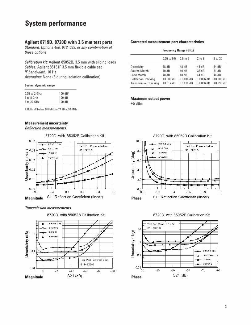
Measurement uncertaintyCurves show the worst-case magnitude and phase uncertainty for reflection and transmissionmeasurements, after calibration. Calibration is theprocess of measuring known standards from a cali-bration kit to characterize a network analyzer’ssystematic (repeatable) errors.
Reflection measurement uncertainty is plotted as afunction of S11 (reflection coefficient). Based on aone-port calibration, using specified calibration kit,with 10 Hz IF bandwidth and no averaging.Assumes a one-port device (S21=S12=0).
Transmission measurement uncertainty is plottedas a function of S21 (transmission gain/loss, in dBfrom reference level). Assumes a well-matcheddevice (S11=S22=0). Based on a full two-port Short-Open-Load-Thru calibration (including isolationwith averaging factor of 8), using specified calibra-tion kit, with 10 Hz IF bandwidth and no averaging.
Measurement port characteristicsThe characteristics indicate performance aftererror-correction (full two-port calibration). Theperformance accuracy is determined by the qualityof calibration standards and how well “known”they are, plus system repeatability, stability, andnoise. Crosstalk is not shown, since isolation cali-bration will reduce crosstalk to the noise floor.
Definitions and Test Conditions
3
Agilent 8719D, 8720D with 3.5 mm test portsStandard, Options 400, 012, 089, or any combination ofthese options
Calibration kit: Agilent 85052B, 3.5 mm with sliding loadsCables: Agilent 85131F 3.5 mm flexible cable setIF bandwidth: 10 HzAveraging: None (8 during isolation calibration)
System dynamic range
0.05 to 2 GHz 100 dB1
2 to 8 GHz 100 dB8 to 20 GHz 100 dB
1. Rolls off below 840 MHz to 77 dB at 50 MHz
Corrected measurement port characteristics
Frequency Range (GHz)
0.05 to 0.5 0.5 to 2 2 to 8 8 to 20
Directivity 48 dB 48 dB 44 dB 44 dBSource Match 40 dB 40 dB 33 dB 31 dBLoad Match 48 dB 48 dB 44 dB 44 dBReflection Tracking ±0.006 dB ±0.006 dB ±0.006 dB ±0.008 dBTransmission Tracking ±0.017 dB ±0.018 dB ±0.066 dB ±0.099 dB
Maximum output power+5 dBm
System performance
Measurement uncertaintyReflection measurements
Transmission measurements
Magnitude
Magnitude
Phase
Phase

4
Agilent 8722D with 2.4 mm test portsStandard, Options 400, 012, 089, or any combination of these options.
Calibration kit: Agilent 85056A, 2.4 mm with sliding loadsCables: Agilent 85133F 2.4 mm flexible cable setIF bandwidth: 10 HzAveraging: None (8 during isolation calibration)
System dynamic range
0.05 to 2 GHz 93 dB1
2 to 8 GHz 93 dB8 to 20 GHz 91 dB20 to 40 GHz 80 dB
1. Rolls off below 840 MHz to 72 dB at 50 MHz
Corrected measurement port characteristics
Frequency Range (GHz)
0.05 to 2 2 to 8 8 to 20 20 to 40
Directivity 42 dB 42 dB 42 dB 38 dBSource Match 41 dB 38 dB 38 dB 33 dBLoad Match 42 dB 42 dB 42 dB 38 dBReflection Tracking ±0.005 dB ±0.010 dB ±0.010 dB ±0.021 dBTransmission Tracking ±0.020 dB ±0.038 dB ±0.048 dB ±0.110 dB
Maximum output power0.05 to 20 GHz: -5 dBm20 to 40 GHz: -10 dBm
System performance (continued)
Measurement uncertaintyReflection measurements
Transmission measurements
Magnitude
Magnitude
Phase
Phase
5
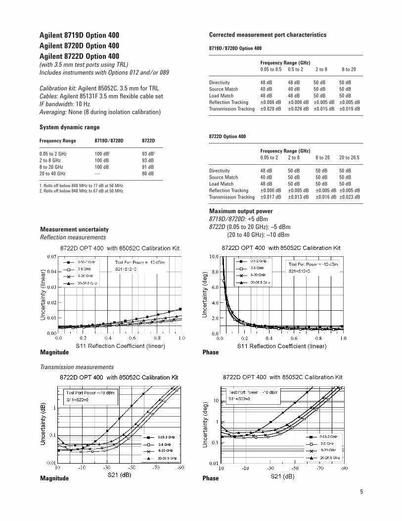
Agilent 8719D Option 400Agilent 8720D Option 400Agilent 8722D Option 400(with 3.5 mm test ports using TRL)Includes instruments with Options 012 and/or 089
Calibration kit: Agilent 85052C, 3.5 mm for TRLCables: Agilent 85131F 3.5 mm flexible cable setIF bandwidth: 10 HzAveraging: None (8 during isolation calibration)
System dynamic range
Frequency Range 8719D/8720D 8722D
0.05 to 2 GHz 100 dB1 93 dB2
2 to 8 GHz 100 dB 93 dB8 to 20 GHz 100 dB 91 dB20 to 40 GHz — 80 dB
1. Rolls off below 840 MHz to 77 dB at 50 MHz2. Rolls off below 840 MHz to 67 dB at 50 MHz
Corrected measurement port characteristics
8719D/8720D Option 400
Frequency Range (GHz)0.05 to 0.5 0.5 to 2 2 to 8 8 to 20
Directivity 48 dB 48 dB 50 dB 50 dBSource Match 40 dB 40 dB 50 dB 50 dBLoad Match 48 dB 48 dB 50 dB 50 dBReflection Tracking ±0.006 dB ±0.006 dB ±0.005 dB ±0.005 dBTransmission Tracking ±0.020 dB ±0.026 dB ±0.015 dB ±0.019 dB
8722D Option 400
Frequency Range (GHz)0.05 to 2 2 to 8 8 to 20 20 to 26.5
Directivity 48 dB 50 dB 50 dB 50 dBSource Match 40 dB 50 dB 50 dB 50 dBLoad Match 48 dB 50 dB 50 dB 50 dBReflection Tracking ±0.006 dB ±0.005 dB ±0.005 dB ±0.005 dBTransmission Tracking ±0.017 dB ±0.013 dB ±0.016 dB ±0.023 dB
Maximum output power8719D/8720D: +5 dBm8722D (0.05 to 20 GHz): –5 dBm
(20 to 40 GHz): –10 dBmMeasurement uncertaintyReflection measurements
Transmission measurements
Magnitude Phase
Magnitude Phase

6
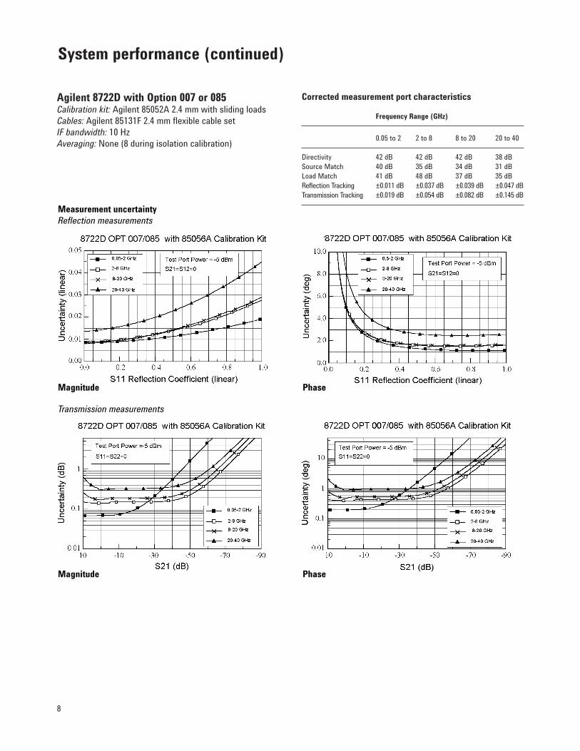
Agilent 8719D, 8720D, 8722D Option 007Agilent 8719D, 8720D, 8722D Option 085Includes instruments with Options 012 and/or 089
Option 007 replaces the standard solid-state trans-fer switch with a mechanical switch to providehigher output power.
Option 085 adds internally controlled 0 to 55 dBstep attenuators (5 dB steps) in the receiver pathof both ports, an RF loop that allows the additionof an amplifier before the transfer switch, and RFloops after the switch that allow insertion of isola-tors, required for measurements above 1 watt. Aninternal reference channel switch is added andinternal bias tees are deleted. This system is capa-ble of full two-port calibrated measurements to 20watts. Measurements up to 100 watts may be possi-ble using specific configurations. Option 085 is notcompatible with Option 400.
System dynamic r1ange
Option 007 Option 085Frequency Range 8719D/20D 8722D 8719D/20D 8722D
0.05 GHz 82 dB 72 dB 77 dB 67 dB0.05 to 2 GHz1 105 dB 98 dB 100 dB 93 dB2 to 8 GHz 105 dB 98 dB 100 dB 93 dB8 to 20 GHz 105 dB 96 dB 100 dB 91 dB20 to 40 GHz — 85 dB — 77 dB
1. Rolls off below 840 MHz to specified value at 50 MHz
Maximum output power
Option 007 Option 0852
8719D/8720D +10 dBm +5 dBm8722D (0.05 to 20 GHz) 0 dBm –5 dBm8722D (20 to 40 GHz) –5 dBm –10 dBm
2. With jumper cable installed between RF out and RF in ports,i.e. no external amplification.
Supplemental characteristics (Option 085)Maximum R-channel input level: 0 dBmMinimum R-channel input level: –34 dBmMaximum RF port input: +43 dBmAttenuators: 55 dB maximum, 5 dB stepsMaximum test port power (no isolators): +30 dBmMaximum test port power (with high power isolators): +43 dBm
System performance (continued)
Option 085 block diagram and examplehigh power measurement setup
Mechanical transfer switch
Source
Samplers
Reference switch
Customer-suppliedbooster amplifier and coupler
RF out RF in +43 dBm max
A
R
B
–55 dB–55 dB
Customer-supplied isolation(for output above +30 dBm)
Ref input 0 dBm max
Amplifierunder test
+43 dBm max output(20 watts)
+43 dBm max input(20 watts)

7
Agilent 8719D or 8720D with Option 007 or 085
Calibration kit: Agilent 85052B 3.5 mm with sliding loadsCables: Agilent 85131F 3.5 mm flexible cable setIF bandwidth: 10 HzAveraging: None (8 during isolation calibration)
Corrected measurement port characteristics
Frequency Range (GHz)
0.05 to 0.5 0.5 to 2 2 to 8 8 to 20
Directivity 48 dB 48 dB 44 dB 44 dBSource Match 40 dB 39 dB 32 dB 30 dBLoad Match 48 dB 45 dB 38 dB 37 dBReflection Tracking ±0.006 dB ±0.010 dB ±0.030 dB ±0.031 dBTransmission Tracking ±0.011 dB ±0.016 dB ±0.070 dB ±0.122 dB
Measurement uncertainty Reflection measurements
Transmission measurements
Magnitude
Magnitude
Phase
Phase
8
Agilent 8722D with Option 007 or 085Calibration kit: Agilent 85052A 2.4 mm with sliding loadsCables: Agilent 85131F 2.4 mm flexible cable setIF bandwidth: 10 HzAveraging: None (8 during isolation calibration)
Corrected measurement port characteristics
Frequency Range (GHz)
0.05 to 2 2 to 8 8 to 20 20 to 40
Directivity 42 dB 42 dB 42 dB 38 dBSource Match 40 dB 35 dB 34 dB 31 dBLoad Match 41 dB 48 dB 37 dB 35 dBReflection Tracking ±0.011 dB ±0.037 dB ±0.039 dB ±0.047 dBTransmission Tracking ±0.019 dB ±0.054 dB ±0.082 dB ±0.145 dB
System performance (continued)
Measurement uncertaintyReflection measurements
Transmission measurements
Magnitude
Magnitude
Phase
Phase

9
Option 012Option 012 adds RF loops that provide directaccess to the A and B samplers in the port 1 andport 2 receivers. This allows transmission meas-urements that bypass the receiver coupler forimproved signal-to-noise and sensitivity. The systemis capable of antenna measurements to –110 dBm at40 GHz, and filter rejection measurements to 120 dB.Use of multiple antennae provides improved signal-to-noise for free space transmission and reflectionmeasurements. The RF loops can also be used tointegrate components into the test set. Adding a 20 dB attenuator increases the test port 0.1 dBcompression level to +30 dBm. With front paneljumpers installed, the system operates as a stan-dard system and meets standard instrument speci-fications.
Supplemental characteristics (Option 012)
Frequency Range (GHz)
0.05 to 0.5 0.5 to 2 2 to 8 8 to 20 20 to 40
Compression1
Test Port 1,2 20 dB 16 dB 15 dB 8 dB 3 dB
Compression1
DirectSampler Input 2 dBm 1 dBm 0 dBm -7 dBm -12 dBm
AverageNoise Floor2 -125 dBm -125 dBm -125 dBm -123 dBm -120 dBm
ReceiverDynamic Range 127 dB 126 dB 125 dB 116 dB 108 dB
1. Input power level that causes 0.1 dB compression in the receiver2. 10 Hz IF BW
Option 012 test set block diagram
Option 400 and 012 test set block diagram
Measure filter rejection to –120 dB
Transfer Switch
Source
Port 1 Port 2
Samplers
A
R
B
R channeljumper
SwitchSplitter
Source
Port 1 Port 2
Samplers
A
R
R2
B
R channeljumper
Samplers
A B
Measure amplifier output to +43 dBm
Samplers
A B
16 dB more sensitivity for antenna test. Improved signal to noise for free space materials test.
Samplers
A B

10
Option 089Option 089 adds frequency offset mode, allowingthe receiver to be offset from the source frequency.This allows direct conversion loss measurement ofmixers without need for a reference mixer. RF andIF frequencies must be within the specified operat-ing range of the instrument. This test set modifica-tion adds an internal reference channel switch anddeletes the reference channel output. Firmwareguides the user through test setup. When not infrequency offset mode, the system operates as astandard system and meets standard instrumentspecifications.
Supplemental characteristics (Option 089)
8719D/8720D 8722D
Reference (R) Input LevelMinimum -34 dBm -34 dBmMaximum (for 0.1 dB compression) -7 dBm -12 dBmMaximum (damage level) 0 dBm 0 dBm
Note: To utilize full instrument receiver dynamic range, measure test signal at port 2. This configuration requires a power splitter and reference mixerto provide a phase lock signal to the R channel input.
System performance (continued)
Analyzer’s guided test setup display
Option 089 test set block diagram
Mechanical transfer switch
R channelinput
LO source
Source
Samplers
Reference switch
Mixerunder test
A
R
RF IFLO
B
Filter

11
Description Specification Code
Frequency CharacteristicsRange
8719D 0.05 to 13.51 GHz S-18720D 0.05 to 20.05 GHz S-18722D 0.05 to 40 GHz S-1
Accuracy (at 23 °C ± 3 °C) ±10 ppm S-1Stability
0 °C to 55 °C ±7.5 ppm COption 1D5 ±0.05 ppm C
Per year (aging) ±3 ppm COption 1D5 ±0.5 ppm C
Resolution 1 Hz S-3System CharacteristicsMaximum Input Level
Damage Level (test port) 30 dBm CReference (F) Input Level (Option 089)
Maximum8719D/8720D –7 dBm C8722D –12 dBm C
Minimum8719D/8720D/8722D –34 dBm C
High Level Trace Noise2
Magnitude (zero-peak)0.05 to 13.5 GHz 0.03 dB C13.5 to 20 GHz 0.04 dB C20 to 40 GHz 0.15 dB C
Phase (zero-peak)0.05 to 13.5 GHz 0.3° C13.5 to 20 GHz 0.4° C20 to 40 GHz 1.5° C
Spectral Purity CharacteristicsHarmonics at maximum output level <–15 dBc CPhase Noise
to 60 kHz from carrier at 2 GHz <–55 dBc Cto 60 kHz from carrier at 20 GHz <–35 dBc C
Nonharmonic Spurious Signalsat 100 kHz offset <–40 dBc Cat 200 kHz offset <–45 dBc Cat >200 kHz offset <–65 dBc C
Description Specification Code
Power CharacteristicsPower Range
8719D/8720D 75 dB C8722D
0.05 to 20 GHz 70 dB C20 to 40 GHz 65 dB C
Maximum Output Power8719D/8720D (Standard, Options. 085, 400) +5 dBm C8719D/8720D (Option 007) +10 dBm C8722D (Standard, Options 085, 400)
0.05 to 20 GHz –5 dBm C20 to 40 GHz –10 dBm C
8722D (Option 007)0.05 to 20 GHz 0 dBm C20 to 40 GHz –5 dBm C
Resolution 0.01 dB S-3Flatness (at 5 dB below maximum output power)
8719D/8720D ±2 dB S-18722D ±3 dB S-1
Power Sweep Range8719D 20 dB S-38720D 20 dB S-38722D 15 dB S-3
Power Linearity±5 dB from reference ±0.35 dB S-1–10 dB from reference ±0.6 dB S-1+10 dB1 from reference ±1 dB S-1
Test Reference Power8719D/8720D (Standard, Options 085, 400) –5 dBm S-38719D/8720D (Option 007) 0 dBm S-38722D (Standard, Options 085, 400) –10 dBm S-38722D (Option 007)
Specifications and characteristics
Frequency Range (GHz)
Description 0.055 0.05 to 25 2 to 8 8 to 20 20 to 40 Code
System CharacteristicsDynamic Range3
8719D/8720D (Standard, Options 085, 400) 77 dB 100 dB 100 dB 100 dB S-18719D/8720D (Option 007) 82 dB 105 dB 105 dB 105 dB S-18722D (Standard4, Options 085, 400) 67 dB 93 dB 93 dB 91 dB 80 dB6 S-18722D (Option 007) 72 dB 98 dB 98 dB 96 dB 85 dB S-1
Receiver 0.1 dB Compression Input Level7 20 dBm 16 dBm 15 dBm 8 dBm 3 dBm C
1. Does not apply to 8722D.2. Trace noise is defined as variation of a high signal level trace due to noise. The
value given represents a noise variation that is three standard deviations awayfrom the trace’s mean value as measured in a 3 kHz IF bandwidth in th fastsweep mode (STEP SWP OFF).
3. The dynamic range specifications apply to transmission measurements using 10 Hz IF BW and response and isolation correction or full two-port correction.Dynamic range is limited by the maximum test port power and the receiver’snoise floor.
4. With 85133E flexible cable on test port.5. Rolls off below 840 MHz to specified value at 50 MHz.6. 77 dB for Option 085.7. For Option 012 direct sampler input compression levels, refer to page 9.
S-1: This performance parameter is verifiable using performance tests documented in the service manual.
S-2: Due to limitations on available industry standards, the guaranteed performanceof the instrument cannot be verified outside the factory. Field procedures canverify performance with a confidence prescribed by available standards.
S-3: These specifications are generally digital functions or are mathematicallyderived from tested specifications, and can therefore be verified by functionalpass/fail testing.
C: Non-warranted performance characteristics are intended to provide informationuseful in applying the instrument. Performance characteristics are representa-tive of most instruments, though not necessarily tested in each unit. Not fieldtested.

12
Full frequency band sweep time (ms)1
Number of Points
Measurement 51 201 401 1601
(Stepped mode/Swept mode)
Single Band Sweep (10 to 12 GHz)Uncorrected 170/56 523/93 999/143 3866/443One-port calibration2 170/56 523/93 999/143 3866/443Two-port calibration3 331/100 1053/173 2024/272 7880/872
Agilent 8719D Full Sweep (0.05 to 13.5 GHz)Uncorrected 612/496 1055/589 1539/651 4371/951One-port calibration2 612/496 1055/589 1539/651 4371/951Two-port calibration3 1217/977 2118/1166 3100/1287 8911/1892
Agilent 8720D Full Sweep (0.05 to 20 GHz)Uncorrected 585/447 1068/580 1548/637 4386/939One-port calibration2 585/447 1068/580 1548/637 4386/939Two-port calibration3 1162/880 2144/1147 3123/1263 8942/1865
Agilent 8722D Full Sweep (0.05 to 40 GHz)Uncorrected 760/581 1281/696 1733/713 4649/995One-port calibration2 760/581 1281/696 1733/713 4649/995Two-port calibration3 1510/1144 2572/1376 3497/1414 9478/1976
Time Domain Conversion4 13 44 90 387
GPIB Data Transfer5 13 18 25 61Binary (Internal)
IEEE754 floating point format32 bit 14 21 31 8964 bit 16 30 48 153ASCII 52 181 355 1391
1. All values are typical.2. S11 one-port calibration, with a 6 kHz IF bandwidth. Includes system retrace time.
Time domain gating is assumed off.3. S21 measurement with full two-port calibration, using a 6 kHz IF bandwidth.
Includes system retrace time and RF switching time. Time domain gating isassumed off.
4. Option 010 only, gating and error-correction are off. Does not include sweep time.5. Measured with an HP Omnibook 5500 133 Pentium computer.
Measurement throughput summary

13
Option 010 time domainWith the time domain option, data from transmis-sion or reflection measurements in the frequencydomain are converted to the time domain using aFourier transformation technique (chirp Z) andpresented on the display. The time domain responseshows the measured parameter value versus time.Markers may also be displayed in electrical length(or physical length if the relative propagationvelocity is entered).
Time stimulus modesStandard stimulusTwo types of time excitation stimulus waveformscan be simulated during the transformations, astep and an impulse.
External stimulusOther time excitation stimulus waveforms can beaccomplished using an external controller.
Low pass stepThis stimulus, similar to a traditional time domainreflectometer (TDR) stimulus waveform, is used tomeasure low pass devices. The frequency domaindata should extend from DC (extrapolated value) toa higher value, the upper limit being defined by thetest configuration used. The time domain responseshows the parameter value versus time (multiplyby the speed of light, c, to obtain electrical lengthor by c and Vrel to obtain physical length). The stepresponse is typically used for reflection measure-ments only.
Low pass impulseThis stimulus is also used to measure low passdevices. The frequency domain data should extendfrom DC (extrapolated value) to a higher value, themaximum frequency determined by the test config-uration. The time domain response shows changesin the parameter value versus time. The impulseresponse can be used for reflection or transmissionmeasurements.
Bandpass impulseThe bandpass impulse simulates a pulsed RF signal(with an impulse envelope) and is used to measurethe time domain response of band-limited devices.The start and stop frequencies are selectable bythe user to any values within the limits of the testset used. The bandpass time domain response also
shows changes in the parameter values versustime. Bandpass time domain responses are usefulfor both reflection and transmission measurements.
Time domain rangeThe “alias-free” range over which the display isfree of response repetition, depends on the fre-quency span and the number of points. Range, innanoseconds, is determined by:
Range = 1/∆F = (Number of points in FrequencyDomain –1)/Frequency Span (GHz)
Range resolutionTime resolution of a time domain response (for exam-ple, 0.3 nanoseconds versus 0.307 nanoseconds).
Range –resolution = time span/(number of points –1)
DistanceRelated to time by speed of light and relative veloc-ity; in space, Vrel =1; for distance to response inreflection measurement, multiply by 1/2.
Distance = 3 x 10⁸ m/sec x Vrel x Time
WindowsThe windowing function can be used to modify (fil-ter) the frequency domain data and thereby reduceovershoot and ringing in the time domain response.Three types of windows are available—minimum,normal, and maximum.
GatingThe gating function can be used to selectivelyremove reflection or transmission time domainresponses. In converting back to the frequencydomain the effects of the responses outside thegate are removed. The location and span of thegate can be controlled by either setting the centerposition and time span of the gate, or by settingthe start and stop time of the gate.
Analyzer options

14
Option 085, high power system This option is designed to permit the measurementof high power amplifiers at RF levels up to 20 Watts(+43 dBm), with full two-port calibration. A switchis added to the reference path so that boosteramplifier response can be ratioed out. To protectthe analyzer from high power levels, this optionallows the addition of isolators at both test portsand includes internally controlled step attenuatorsbetween couplers and samplers. Bias tees, isolatorsand booster amplifiers are not included. Networkanalyzers with option 085 can also be configuredto operate as standard instruments with degradedpower accuracy or as instruments capable of mak-ing single connection multiple measurements.
Option 007, mechanical transfer switchThis option replaces the solid state transfer switchwith a mechanical switch in the test set, increasingthe test port power and dynamic range.
Option 089, frequency offset modeThis option adds the ability to offset the sourceand receiver frequencies for frequency translatedmeasurements. This provides the instrument withmixer measurement capability. It also provides agraphical setup that allows easy configuration ofyour measurement.
Option lD5, high stability frequency referenceThis option provides the analyzer with ±0.05 ppmtemperature stability from 0 °C to 60 °C (refer-enced to 25 °C).
Option 012, direct access receiver configurationThis option provides front panel access to the Aand B samplers for improved receiver sensitivity.Option 012 improves signal-to-noise in free spacematerials measurements with the use of multipleantennas. Direct connection of the reflectionantennas to the A and B samplers eliminates inter-nal reflections of the transmitted signal in thereflection path, improving the signal to noise ratio.Option 012 also allows you to add attenuatorsbetween the couplers and samplers, increasing thepower handling capability of the instrument.
Option 400, fourth sampler and TRL calibration firmware This option converts the built-in test set to a four-sampler configuration, allowing TRL calibration.This provides the highest accuracy for non-coaxialenvironments, such as on-wafer probing, in-fixtureor waveguide measurements.
Analyzer options (continued)
15
Measurement capabilitiesNumber of measurement channels2; each fully independentParametersS11: Forward reflection (input match)S21: Forward transmission (insertion loss/gain/phase)S12: Reverse transmission (reverse isolation)S22: Reverse reflection (output match)A, B, R: Receiver signal levelA/R, B/R, A/B: Ratioed receiver signalsAuxiliary Input: DC voltage on AUX INPUTParameter conversionZ – Reflection: equivalent parallel impedanceY – Reflection: equivalent parallel admittanceZ – Transmission: equivalent series impedanceY – Transmission: equivalent series admittance1/S: complex inverse of S-parametersDisplay formatsCartesianLog/linear magnitude, phase, group delay, SWR, real and imaginarySmith chartLog/linear magnitude and phase, R+jX, G+jB, or real/imag-inary markersPolarLinear/log magnitude, phase, or real and imaginary markers
MarkersNumber of markers5 per channel; 1 “active” per channel; can be coupled(same stimulus in both channels) or uncoupled(independent stimulus in each channel).
Displayed marker valuesAll activated markers with both stimulus andresponse values are displayed; with dual-channeluncoupled, can display up to 10 markers; all butactive marker replaced by bandwidths or statistics,when enabled.
Stimulus resolutionDiscrete (actual measurement points) or continu-ous (linearly interpolated between points, with 1 Hzresolution).
Delta markersDisplays difference in both stimulus (e.g. frequency)and response (e.g. dB) between active marker andreference marker; reference marker may be any offive markers, or a sixth fixed marker given anyarbitrary position on display.
Polar format markersLinear magnitude and phase; log magnitude (dB)and phase; real and imaginary.
Smith chart format markersLinear magnitude and phase; log magnitude (dB)and phase; real and imaginary (R+jI); compleximpedance (R+jX); complex admittance (G+jB).
SearchFinds maximum, minimum, or target value.
BandwidthFinds and displays center frequency, bandwidth ata user-defined level (for example, –3 dB), Q factor,and shape factor (ratio of 60 dB and 6 dB band-widths); updates while tuning with tracking enabled;valid for band-pass or band-reject (notch) filters.
StatisticsCalculates and displays mean, standard deviation,and peak-to-peak deviation of trace; active betweentwo markers or over entire trace.
TrackingPerforms new search (min/max/target) at end ofeach sweep; if disabled, occurs once on demand.
Marker-to functionsSet start, stop or center to active marker stimulusvalues; set span to active and delta marker stimu-lus values; set reference to active marker responsevalue; set electrical delay to active marker phaseresponse value.
Group delay characteristicsGroup delay is computed by measuring the phasechange within a specified frequency step (deter-mined by the frequency span, and the number ofpoints per sweep).
Aperture Selectable. Maximum aperture: 20% of frequencyspan. Minimum aperture: (frequency span)/(num-ber of points–1).
RangeThe maximum delay is limited to measuring nomore than 180° of phase change within the mini-mum aperture. Range= 1/(2 x minimum aperture).
AccuracyIn general, the following formula can be used todetermine the accuracy, in seconds, of a specificgroup delay measurement:±(0.003 x Phase accuracy(deg))/Aperture(Hz).
Capabilities

16
Source controlSweep limitsSet start/stop or center/span of the stimulusparameter (frequency, power, time) directlythrough the source control keys and the controlknob, the step keys, or the data entry keyboard.
Sweep typeSet a linear or logarithmic sweep, an arbitrarilydefined frequency list, a power sweep, or a CW(single frequency) type of sweep.
Fast swept listDefine up to 30 different subsweep frequencyranges in any combination of CW, CW-delta F, orstart-stop sweep modes. Set test-port power levelsand IF bandwidth independently for each segment.
Measured number of points per sweepLinear frequency: choose 3, 11, 21, 51, 101, 201,401, 801, 1601 points.
Source couplingSet a coupled channel sweep (same stimulus condi-tions on both channels) or an uncoupled channelsweep (ind ependent stimulus conditions).
Chop/alternate sweepsSelect whether to alternately or simultaneously(chop) measure channels when measuring withtwo-port calibration. Chop mode is faster, whilealternate mode optimizes dynamic range. Thedefault is chop mode.
Sweep timeSet sweep time in seconds, minutes, or hours.Minimum sweep time is dependent on number ofdata points per sweep and selected IF bandwidth.
Auto sweep timeSelect auto sweep time by entering zero secondssweep time. The analyzer will sweep at the mini-mum sweep time for any subsequently selectedstimulus conditions. Auto sweep time is the defaultcondition.
Sweep triggerSet to either continuous, hold, single, group sweep,or external trigger. Set external trigger to take acomplete sweep or to measure individual points ina frequency, power, or list sweep.
PowerControl the test port signal by setting the internalattenuator over a 70 dB range. Power trip automat-ically reduces source power to its minimum valuewhen excessive signal levels are incident on the
receiver test port. A caution message is also displayed.Source power range differs depending on the selectedoptions. Power slope can be set in dBm/GHz.
Continuous switchingContinuously switches the RF output between port1 and port 2; enables simultaneous active displayof forward and reverse parameters.
Power meter calibrationDescriptionUse a power meter to set leveled input or outputpower at the device under test at a single point oran entire sweep. With an Agilent 436A, 437B, or438A power meter connected, the calibrationsweep measures the actual test port power. Afterthe calibration is enabled, the internal RF sourcepower is adjusted (within the range of –85 to +10 dBm)to achieve the selected power at the input of thedevice under test rather than at the test port out-put. GPIB control of the power meter for normal-ization or leveling is built-in. Logarithmic, linear,CW, and list sweeps can be calibrated.
Update CalibrationSelect continuous leveling (requires a power splitter)by measuring and updating source power on eachsweep or use a correction table (to modify sourcepower) which is created with an initial single sweep.
Number of readingsMake single or multiple power meter readings ateach frequency.
Data accuracy enhancementDescriptionMeasurement calibration is the process that signifi-cantly reduces measurement uncertainty due tosystem directivity, source and load match, trackingand crosstalk. A wide range of calibrations areavailable for the Agilent 8719D/20D/22D. Full two-port calibration removes all the systematic errors,resulting in the most accurate measurements.
Frequency responseSimultaneous magnitude and phase correction offrequency response errors for either reflection ortransmission measurements. Requires a short oropen circuit termination (reflection), or a throughconnection (transmission).
Response and isolationCompensates for frequency response and directivity(reflection) or frequency response and crosstalkerrors. Requires an open, short, and load circuittermination (reflection) and a through connectionand load termination (transmission).
Capabilities (continued)

17
One-port calibrationUses test set port 1, or port 2, or both to correctfor directivity, frequency response, and sourcematch errors. Requires open, short, and load.
Two-port calibrationCompensates for directivity, source match, reflec-tion frequency response, load match, transmissionfrequency response, and crosstalk. Crosstalk cali-bration can be eliminated. Requires open, short,and load terminations for both ports plus athrough connection.
TRL*/LRM* calibrationCompensates for directivity, reflection and trans-mission frequency response, and crosstalk in boththe forward and reverse directions. Especially suit-able for calibrating non-coaxial environments, suchas in test fixtures. Requires through, reflect, andline or match standards. TRL*/LRM* is a specialimplementation of TRL/LRM calibration modifiedfor the three-sampler receiver in the standardAgilent 8719D/20D/22D.
TRL/LRM calibrationWith Option 400 (four-sampler receiver). TRL/LRMprovides the highest accuracy for non-coaxial testenvironments such as in fixture, on-wafer or inwaveguide. Compensates for directivity, reflectionand transmission frequency response, andcrosstalk in both forward and reverse directions.
One-path, two-port calibrationProvides a full two-port error corrected measure-ment when the device under test is turned aroundand measured in both directions.
Calibration FeaturesFast two-portCompensates for 12-terms, similar to full two-port,except that 2 of 4 raw parameters (forward or reverse)are continuously re-measured while the remaining 2are periodically updated at a user-selectable rate.Improves update rate for tuning, and reduces unneces-sary wear on transfer switch in Option 007. [Meas] keyor contact closure at rear panel foot switch connectorcauses full two-port update.
Interpolated error correctionWith any type of accuracy enhancement applied,interpolated mode recalculates the error coeffi-cients when the test frequencies are changed. Thenumber of points can be increased or decreasedand the start/stop frequencies can be changed, butthe resulting frequency range must be within theoriginal calibration frequency range. System per-formance is not specified for measurements withinterpolated error correction applied.
Set Zo
Redefine the characteristic impedance of a meas-urement to a value other than 50 or 75 ohms.
Velocity factorEnter the velocity factor of your propagation medium toconvert equivalent electrical length to physical length.
Electrical delayAdd or subtract delay (linear phase slope), up to+10 µs, similar to “line stretchers,” both coax orwave-guide (dispersive) modes. Secondary readoutin distance computed from velocity factor.
Reference plane extensionRedefine the reference plane after calibration. Anew reference plane is defined in seconds of delayfrom the test port and ranges between ±l seconds.Similar to electrical delay, but applied appropriate-ly to each of four parameters.
Select default calibration kitSelect from a list of standard calibration kits: 7 mm,3.5 mm, Type-N 50 ohm, Type-N 75 ohm, 2.4 mm,2.92 mm, and 3.5 mm TRL. You can also define thestandards (for example, open circuit capacitancecoefficients, offset short length, or fixed loads) of auser-defined kit.
Segmented calibrationCalibration remains valid for any frequency seg-ment (in frequency list mode), after calibrating allsegments with a single calibration.
Receiver power calibrationAdjusts nonratioed receiver inputs to absolute (non-ratioed) power level. Displays absolute power in dBm.Requires reference sweep of known source power.
Data averagingIF bandwidthThe IF bandwidth is selectable from 6 kHz to 10 Hzbandwidth to reduce the effective displayed noisefloor of the instrument.
Weighted sweep-to-sweep averagingAverages vector data on each successive sweep.A(n) = S(n)/F + (1–1/F) x A(N–1) where A(n) is thecurrent average, S(n) is the current input signaland F is the averaging factor. Averaging factorsrange from 1 to 999.
Trace smoothingSimilar to video filtering, this function computesthe moving average of adjacent data points.Smoothing aperture defines the trace width (num-ber of points) to be averaged, and ranges from0.25% to 20% of the trace width. This function alsosets the aperture for group delay measurements.

18
Display controlDisplay formatsSingle channel dual channel overlay (both traceson one graticule), dual channel split (each trace onseparate graticules).
Trace functionsDisplay dataDisplay current measurement data, memory data, orcurrent measurement and memory data simultaneously.
Trace mathVector division or subtraction of current linearmeasurement values and memory data.
Display annotationsStart/stop, center/span, CW frequency, sourcelevel, scale/div, reference level, marker data, soft-key functions, warning and caution messages, traceidentification, and pass/fail indication.
Reference positionRanges from the 0 (bottom) to 10 (top) graticuleposition.
AutoscaleAutomatically selects scale resolution and refer-ence value to center the trace on the display gratic-ules for easy viewing.
Electrical delayOffset measured phase or group delay by a definedamount of electrical delay, in seconds. Operatessimilarly to an electronic line stretcher. Amount ofelectrical delay can range between ±l seconds.
Frequency blankingBlank out all frequency information on the display.Requires an instrument preset to re-enable fre-quency information on the display.
TitleAdd custom titles (49 characters maximum) to thedisplayed measurement. Titles will be plotted whenmaking hardcopies. Titles can also be used to dis-play operator messages or prompts for a manualadjustment during a test sequence.
Adjust displayControl the intensity and background intensity val-ues of the display. Also, customize the color, value,and brightness of the data traces, memory traces,reference lines, graticules, text, and warning mes-sages. Default colors can be recalled along withone set of user-defined display values. Control is in% of full range.
Save/Recall storageInstrument stateUp to 31 instrument states can be stored internallyor recalled via the SAVE/RECALL menu. Instrumentstates include all control settings, active limit lines,active list frequency tables, memory trace data,active calibration coefficients, and custom displaytitles. Storage is in non-volatile memory.
Test sequencesSix measurement sequences can be stored orrecalled via the sequencing menu. Sequences mayalso be recalled from Preset menu. Sequence regis-ter 6 is part of non-volatile storage and is not erasedduring a power cycle. If sequence 6 is titled AUTO, itwill be executed when power is switched on.
Disk driveData, instrument states (including calibrationdata), user graphics, data plots (HP-GL commands),and test sequences can be stored on disk, using theanalyzer’s built-in disk drive or any external diskdrive with command subset CS/80. Data files canbe stored in MS-DOS format or Hewlett-Packard’sstandard LIF format in binary or ASCII formats(compatible with the Agilent 85150A microwavedesign system). A disk to be used for data storagecan be initialized directly by the analyzer.
Data hardcopyData plottingHard copy plots are automatically produced withHP-GL compatible graphics printers such as the HPDeskJet or LaserJet (in single color or multi-colorformat). The analyzer provides Centronics, RS-232C,and GPIB interfaces.Configure plotsConfigure plots completely from the network ana-lyzer by defining pen color and line type for data,text markers, graticules, and memory traces.FunctionsPlot trace(s), graticule(s), markers(s), or textincluding operating and system parameters.QuadrantsPlot entire display fullpage sized or in one of fourdifferent quadrants of the plotter paper.
Data listingsPrintouts of instrument data are directly producedwith a printer such as the HP DeskJet 520, LaserJet,or 560C or PaintJet 3630A. Select a standard (sin-gle color) or color print. Printouts can includeeither the graphical display image (excluding soft-key label), or lists of numeric data; one line perstimulus point, with up to five columns defined bycurrently active parameters.
Capabilities (continued)

19
System CapabilitiesLimit linesDefine test limit lines that appear on the displayfor go/no go testing. Lines may be any combinationof horizontal, sloping lines, or discrete data points.Limit test TTL output available for external controlor indication.
Operating parametersDisplay, print or plot current instrument operatingparameters.
TransformWhen time domain (Option 010) is present, selectsthe time domain transform menu.
Instrument modeSelect external source, tuned receiver, or frequencyoffset mode.
External source modeThe receiver (input R) detects and phase-locks toany externally generated CW signal. Receiverinputs A and B will measure this same frequencyfor comparison or tracking measurements.
AutoThe input signal frequency is counted and displayed.
ManualMeasures the input signal closest to the frequencyspecified by the user (within –0.5 to +5 MHz).
Tuned receiverTunes the receiver for a synthesized CW input sig-nal at a precisely specified frequency. The timebases of the external RF source or sources must betied to the external reference input of the networkanalyzer (rear panel BNC). The built-in RF sourceis not used.
Frequency offset on/offSets the RF source to be swept at a frequency thatis offset from the receiver as required in a sweptRF/IF, fixed LO, mixer test. The maximum delaybetween the RF source and the R channel input is0.3 microseconds. Frequency offset mode requiresRF and IF frequencies to be in the specific range ofthe instrument.
Offset valueSet the offset frequency value.
Service menuSelect the desired service test, service diagnostic,service, or verification mode.
Test sequencesDescriptionCreate, edit, save, or recall a series of front-panelkeystrokes to automate a measurement. Each ofthe six sequence registers can hold approximately200 instructions. Create or edit a sequence byselecting the sequence menu and then simply per-forming the front-panel keystrokes that would nor-mally be used to make a manual measurement.Test sequences may contain basic stimulus andmeasurement functions (frequency, power, parame-ter, format, scale) advanced operations (timedomain, limit testing, display marker values), andbasic logical branching (for example, IF limit testfails DO sequence 5). Completed sequences arethen saved and can be executed when you areready to repeat the test.
StorageTest sequences can be stored internally in RAM, toan internal or external disk drive, or loaded from acomputer over the GPIB interface. Sequence 6 issaved in non-volatile storage and can be used as anautostart routine when titled AUTO.
BranchingBranch to another sequence on limit test pass/failor the loop counter value. Subroutines are alsopossible via GOSUB.
Other GPIB instrumentsSend simple commands to GPIB instruments viathe title string.
Test sequence BNC outputSet TTL high or low on the analyzer rear panel output.
General purpose input/outputRead or write bits to the output port to controlexternal devices such as part handlers. Eight out-put and five input TTL lines are available on theparallel port of the analyzer.
Other functionsPause/continue, wait, title sequence, printsequence, duplicate sequence, pause, and select.
20
GPIB (remote) programmingInterfaceGPIB interface operates to IEEE 488-1978 and IEC625 standards and IEEE 728-1982 recommendedpractices.
AddressingThe GPIB address of the analyzer can be verifiedor set from the front panel via the local menu andcan range from 0 to 30 decimal (factory set at 16).
Pass controlAllows the analyzer to request control of the GPIB(when an active controller is present) whenever itneeds to output to a plotter or printer.
System controllerAllows the analyzer to become a controller on theGPIB to directly control a plotter or a printer.
Talker/listenerAllows the analyzer to become a GPIB talker/ lis-tener when an external controller is present.
Transfer formatsBinary (internal 48-bit floating point complex for-mat), ASCII and 32- or 64-bit IEEE 754 floatingpoint format.
User-accessible graphicsUsing a subset of HP graphics language (HP-GL),vector or text graphics may be written on the ana-lyzer via GPIB. Up to 5 kbytes of data can bestored at one time (4 bytes per vector, 2 bytes percharacter).
Interface function codesSHI, AHI, T6, L4, SRI, RLI, PPO, DC1, DT1, Cl, C2, C3, CIO, E2
UpgradesRefer to Configuration Guide.
SecurityFrequency blankBlanks all frequency information from display,including markers; requires FACTORY PRESET tore-enable.
Reset memoryWrites binary zeros to all non-volatile memory reg-isters, erasing all instrument state and calibrationdata; used with PRESET.
General characteristicsFront panel connectorsConnector typeAgilent 8719D/8720D: 3.5 mm precisionAgilent 8722D: 2.4 mm precision
Impedance50 ohms (nominal)
Rear panel connectorsExternal reference frequency input (EXT REF INPUT)Frequency: 1, 2, 5, and 10 MHz (±200 Hz at 10 MHz)Level: –10 dBm to +20 dBm, characteristicallyImpedance: 50 ohms
High-stability frequency reference output (Option 1D5)Frequency: 10.0000 MHzFrequency stability (0 °C to 55 °C): ±0.05 ppmDaily aging rate (after 30 days): <3 x 10⁻⁹/dayYearly aging rate: 0.5 ppm/yearOutput: 0 dBm minimumNominal output impedance: 50 ohms
External auxiliary input (AUX INPUT)Input voltage limits: –10 V to +10 V
External AM input (EXT AM)±l volt into a 5 kΩ resistor, 1 kHz maximum, resultingin approximately 8 dB/volt amplitude modulation.
External trigger (EXT TRIGGER)Triggers on a negative TTL transition or contactclosure to ground.
Test sequence output (TEST SEQ)This connector outputs a TTL signal which can beprogrammed by the user in a test sequence to behigh or low. By default, this output provides an end-of-sweep TTL signal. (For use with part handlers.)
Limit test output (LIMIT TEST)This connector outputs a TTL signal of the limittest results. Pass: TTL high; Fail: TTL low.
Test port bias input (except Option 085)Maximum voltage: +30 VdcMaximum current (no degradation in RF specifications):
±200 mAMaximum current: ±lA
External monitor: VGA video outputThis connector drives external VGA monitors.
GPIBThis connector allows communication with com-patible devices including external controllers,printers, plotters, disk drives, and power meters.
Capabilities (continued)

21
Parallel portThis connector is used with parallel (or Centronicsinterface) peripherals such as printers and plot-ters. It can also be used as a general purpose I/Oport, with control provided by test sequencingfunctions.
RS-232This connector is used with serial peripherals suchas printers and plotters.
DIN keyboardThis connector is used for the optional AT compatiblekeyboard for titles and remote front-panel operation.
Internal memoryTypical data retention time with 3 V, 1.2 Ah battery:At 25 °C: 11,904 days (32.6 years)At 40 °C: 1244 days (3.4 years)At 70 °C: 250 days (0.68 year)
Line power48 to 66 Hz, 115 V nominal (90 V to 132 V) or 230 V nominal(198 V to 264 V), 280 VA maximum
WeightNet: 25 kg (54 lb)Shipping: 28 kg (61 lb)
Cabinet dimensions222 mm (H) x 425 mm (W) x 457 mm (D) (8.75 x 16.75 x 18 in)(These dimensions exclude front and rear panel protrusions.)
VentilationAllow 100 mm (4 in.) around rear and sides.
Environmental CharacteristicsGeneral ConditionsRFI and EMI susceptibilityDefined by VADE 0730, CISPR Publication 11, andFCC Class B Standards.
ESD (electrostatic discharge)Must be eliminated by use of static-safe work pro-cedures and an anti-static bench mat (such asAgilent 92175T).
DustThe environment should be as dust-free as possible.
Operating conditionsOperating temperature: 0 °C to 55 °CError-corrected temperature Range: ±1 °C of calibrationtemperatureHumidity: 5% to 95% at 40 °C (noncondensing)Altitude: 0 to 4500 meters (15,000 feet)
Non-operating storage conditionsTemperature: –40 °C to +70 °CHumidity: 0 to 90% relative at +65 IC (noncondensing)Altitude: 0 to 15,240 meters (50,000 feet)
457 mm(18 inches)
TOP
SIDEREAR222 mm
(8.75 inches)
425 mm(16.75 inches)

22
Agilent 85071B Materials Measurement SoftwareDescriptionThe 85071B software uses broadband S-parametermeasurements to determine the electromagneticproperties of dielectric and magnetic materials.The software calculates both the complex permit-tivity εr (or dielectric constant) and permeabilityµr, including loss factors. Depending on the net-work analyzer and fixtures used, measurementscan extend from 100 MHz to 110 GHz. The softwareoffers the choice of four algorithms, each designedto address specific measurement needs.
Operating requirementsStandard: Requires MS-DOS on an HP Vectra (or any 100%-compatible PC-AT computer) compatible with MicrosoftWindows 3.0 or higher with mouse. Requires >20 Mbytehard disk and >640 Kbytes RAM.
Option 300: Substitutes HP BASIC Software for the stan-dard version for operation with HP 9000 series 300 con-trollers. Requires BASIC 5.0 or higher and 2 Mbytes ofRAM.
Performance summaryFrequency range: 100 MHz to 110 GHz (characteristically,depending on network analyzer, fixture, and material).
Format: εr’, εr”, µr’, µr”, tan δ, tan δm, or Cole-Cole plots;tabular listings of data.
Stimulus control: Frequency range, number-of-points, andlinear or log sweep.
Calibration: The software can use any calibration includinga calibrated response gated in the time domain.
Accuracy: 1 to 2%
Fixture: The software works with simple transmission lines:coaxial airlines, or rectangular waveguide containing across-sectional sample of the material-under-test.
Data display: Displays current measurement data, and cansave/display 3 memory traces for comparison.
Data storage: Save/recall/export data via disk in MS-DOS® ASCII format or HP BASIC BDAT format (HP LIFbinary).
Agilent 85070B Dielectric Probe KitDescriptionThe 85070B dielectric probe kit allows convenientnon-destructive testing of materials using theopen-ended coaxial probe method. The probe,together with its own dedicated software, deter-mines the complex permittivity of a wide variety ofliquids, semi-solids, and solids. Since the probe kitmeasures only permittivity, only non-magneticmaterials should be measured. Measurements areefficient and cost-effective because the testing isnon-destructive and there is no need for samplepreparation or special fixtures.
Operating requirementsStandard: Requires MS-DOS on an HP Vectra (or any 100%-compatible PC-AT computer) compatible with MicrosoftWindows 3.0 or higher with mouse. Requires >20 Mbytehard disk and >640 Kbytes RAM.
Option 300: Substitutes HP BASIC Software for the stan-dard version for operation with HP 9000 series 300 con-trollers. Requires BASIC 5.0 or higher and 2 Mbytes ofRAM.
Performance summaryFrequency range: 200 MHz to 20 GHz (typical, depending onnetwork analyzer, fixture, and material).
Probe TemperatureRange: –40 °C to +200 °CRate: <10°C per minute
Format: εr’, εr”, tan δ, or Cole-Cole diagram in linear format.
Stimulus control: Frequency range, number-of-points, andlinear or log sweep.
Calibration: Guided, using open, short (included), and deion-ized water. Supports user-defined standards.
AccuracyDielectric constant, εr’: ±5%Loss tangent, tan δ, εr”/εr’: ±0.05
Data display: Displays current measurement data, and cansave/display up to three memory traces for comparison.
Data storage: Save/recall/export data via disk in MS-DOS® ASCII format or HP BASIC BDAT format (HP LIFbinary).
Software

23
A wide range of accessories support the Agilent8720 family of network analyzers, including cali-bration kits, verification kits, cables and adaptersin both 7 mm, 3.5 mm, Type-N, and 2.4 mm coaxand in the standard waveguide bands. The stan-dards used in the 3.5 mm, Type-N, and 2.4 mm cal-ibration and verification kits use precision slotlessconnectors (PSC-3.5, PSC-N, and PSC-2.4).
Calibration kitsVector accuracy enhancement procedures requirethat the systematic errors of the measurement sys-tem be characterized by measuring known devices(standards) on the system over the frequencyrange of interest. Agilent Technologies offers thefollowing types of calibration kits:
Standard calibration kitsContain open circuits, short circuits, and bothfixed and sliding terminations in both sexes for allconnector types (except 7 mm, a sexless connec-tor). Connector gauges are included in these kitsfor maintaining each standard’s connector inter-face. Standard calibration kits that include RTLadapters and devices are also available in 7 mmand 3.5 mm connectors.
Precision calibration kitsHave precision 50Ω airline(s) for performing theThru-Reflect-Line (TRL) calibration. These kits alsocontain the open circuit, short circuit, and fixedterminations used for traditional open-short-loadcalibration techniques.
Accessories
Calibration kits
Frequency Return ResiduaI ResiduaICal Kit Type Range (GHz) Connector Return Loss, Return Loss, Loss, Airline Directivity2 Source Match2
and Name fmin–fmax Type Fixed Load Sliding Load at fmax at fmax at fmax
Precision85052C 0.045 to 26.5 3.5 mm ≥46 dB, DC to 2 GHz — 50 dB 50 dB 50 dB
Standard85050B 0.045 to 18 7 mm ≥52 dB, DC to 2 GHz ≥52 dB, 2 to 18 GHz — 45 dB 30 dB 85052B 0.045 to 26.5 3.5 mm ≥44 dB, DC to 3 GHz ≥44 dB, 3 to 26.5 GHz — 44 dB 30 dB85054B 0.045 to 18 Type-N ≥48 dB, DC to 2 GHz ≥42 dB, 2 to 18 GHz — 42 dB 30 dB85056A 0.045 to 50 2.4 mm ≥42 dB, DC to 4 GHz ≥36 dB at 50 GHz — 38 dB 31 dB
Economy85050D 0.045 to 18 7 mm ≥38 dB, DC to 18 GHz — — 36 dB 30 dB85052D 0.045 to 26.5 3.5 mm ≥30 dB at 26.5 GHz — — 36 dB 29 dB85054D 0.045 to 18 Type-N ≥34 dB at 18 GHz — — 34 dB 28 dB85056D 0.045 to 50 2.4 mm ≥26 dB at 50 GHz — — 26 dB 23 dB85056K 0.045 to 40 2.92 mm ≥26 dB at 40 GHz — — 25 dB 22 dB
WaveguideX11644A1 8.2 to 12.4 WR-90 ≥42 dB,8.2 to 12.4 GHz 50 dB 40 dB 30 dBP11644A1 12.4 to 18 WR-62 ≥42 dB,12.4 to 18 GHz 50 dB 40 dB 30 dBK11644A1 18 to 26.5 WR-42 ≥42 dB,18 to 26.5 GHz 50 dB 40 dB 30 dBR11644A 26.5 to 40 WR-28 — 46 dB 50 dB 40 dB 30 dB
Electronic85060A3 1 to 18 7 mm — — — 44.5 dB 39.5 dB
Option 001 0.45 to 2 7 mm — — — 51 dB 44.5 dB85062A3 1 to 26.5 3.5 mm — — — 41.5 dB 35.5 dB
Option 001 0.45 to 2 3.5 mm — — — 50.5 dB 43.5 dB85064A3 1 to 18 Type-N — — — 44.5 dB 39.5 dB
Option 001 0.45 to 2 Type-N — — — 50 dB 43.5 dB
1. Airline return loss, directivity, and source match are typical values for these calibration kits.2. Residuals based on Agilent 8720D at fmax =20 GHz for 3.5 mm kits or on Agilent 8722D at fmax= 40 GHz for 2.4 mm kits.3. Requires an Agilent 85060C control unit.

24
Economy calibration kitsInclude the open circuit, short circuit, and fixedtermination standards but not sliding terminationsor gauges. Gauges can be ordered separately.
Waveguide calibration kitsContain two coax-to-waveguide adapters with pre-cision flanges, a flush short circuit, a precisionwaveguide line section, and either sliding or fixedterminations. They support calibration based onTRL*, offset load, or short/offset-short/load/thrumethods.
Electronic calibration kitsRequire an Agilent 85060C control unit for opera-tion and Agilent 85060 series calibration modulesof the appropriate connector type. The calibrationmodules is programmed by a control unit to pres-ent many different impedances to the test ports. Afull two-port calibration can be done with a singleconnection. Each standard calibration kit containsthe two-port calibration module and a torquewrench for proper connection. Options are avail-able to add a lowband module to the kit, and tochange the sex of the connectors of the module.
Verification kitsMeasuring known devices, other than the stan-dards used in calibration, is an easy way to verifythe correct operation of an Agilent 8719D/20D/22Dnetwork analyzer system. Agilent offers the follow-ing verification kits which contain precisiondevices, with data traceable to NIST used to verifythe analyzer’s error-corrected measurement per-formance.
• 85051B 7 mm verification kit; 0.045 to 18 GHz• 85055A Type-N verification kit; 0.045 to 18 GHz• 85053B 3.5 mm verification kit; 0.045 to 26.5 GHz• 85057B 2.4 mm verification kit; 0.045 to 50 GHz
Test port return cablesTest port cables are available in the 7 mm, 3.5 mm,Type-N, and 2.4 mm connectors types. All cablesconnect directly to the special ruggedized test portof the network analyzer test port (NMD connector).Agilent offers the following cable choices:
• Single cables in semi-rigid and flexible • Cable set in semi-rigid and flexible
A single long cable with an appropriate test portadapter is best for applications where the testdevice requires a connection next to the test portfor mechanical rigidity. A set of cables offers theflexibility required to position the test devicesaway from the test set.
Semi-rigid cables offer excellent performance andare suitable for applications where the connectorsof the test device are “in-line” or parallel. Flexiblecables are ideal for manufacturing environmentssince they are more rugged and have a tighterbending radius than semi-rigid cables. Semi-rigidcables are warranted for 90 days; flexible cablesare warranted for 1 year.
Network AnalyzerTest Set
Network AnalyzerTest Set
Test PortAdapterDevice
UnderTest
Single CableDeviceUnderTest
Cable Set
25
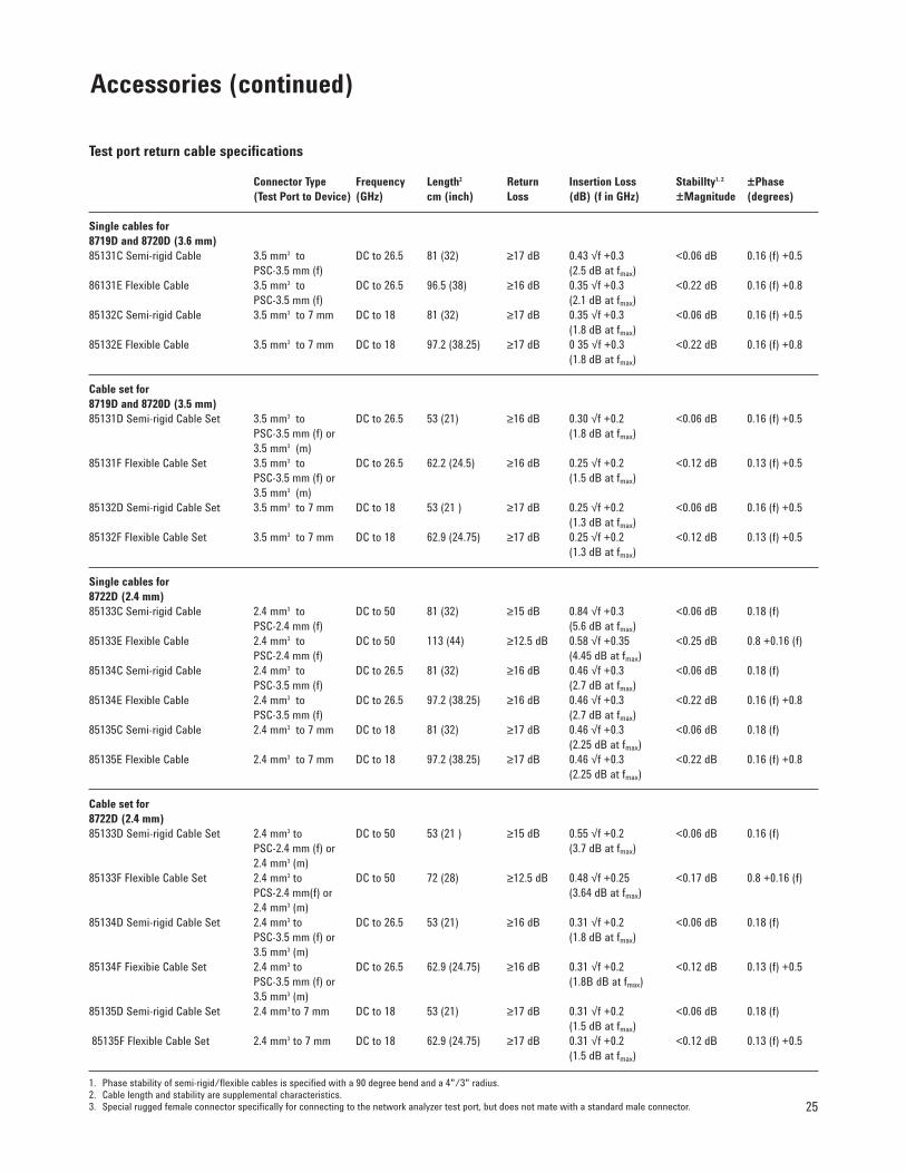
Test port return cable specifications
Connector Type Frequency Length2 Return Insertion Loss Stabillty1, 2 ±Phase (Test Port to Device) (GHz) cm (inch) Loss (dB) (f in GHz) ±Magnitude (degrees)
Single cables for 8719D and 8720D (3.6 mm)85131C Semi-rigid Cable 3.5 mm3 to DC to 26.5 81 (32) ≥17 dB 0.43 √f +0.3 <0.06 dB 0.16 (f) +0.5
PSC-3.5 mm (f) (2.5 dB at fmax) 86131E Flexible Cable 3.5 mm3 to DC to 26.5 96.5 (38) ≥16 dB 0.35 √f +0.3 <0.22 dB 0.16 (f) +0.8
PSC-3.5 mm (f) (2.1 dB at fmax)85132C Semi-rigid Cable 3.5 mm3 to 7 mm DC to 18 81 (32) ≥17 dB 0.35 √f +0.3 <0.06 dB 0.16 (f) +0.5
(1.8 dB at fmax)85132E Flexible Cable 3.5 mm3 to 7 mm DC to 18 97.2 (38.25) ≥17 dB 0 35 √f +0.3 <0.22 dB 0.16 (f) +0.8
(1.8 dB at fmax)
Cable set for 8719D and 8720D (3.5 mm)85131D Semi-rigid Cable Set 3.5 mm3 to DC to 26.5 53 (21) ≥16 dB 0.30 √f +0.2 <0.06 dB 0.16 (f) +0.5
PSC-3.5 mm (f) or (1.8 dB at fmax)3.5 mm3 (m)
85131F Flexible Cable Set 3.5 mm3 to DC to 26.5 62.2 (24.5) ≥16 dB 0.25 √f +0.2 <0.12 dB 0.13 (f) +0.5PSC-3.5 mm (f) or (1.5 dB at fmax)3.5 mm3 (m)
85132D Semi-rigid Cable Set 3.5 mm3 to 7 mm DC to 18 53 (21 ) ≥17 dB 0.25 √f +0.2 <0.06 dB 0.16 (f) +0.5(1.3 dB at fmax)
85132F Flexible Cable Set 3.5 mm3 to 7 mm DC to 18 62.9 (24.75) ≥17 dB 0.25 √f +0.2 <0.12 dB 0.13 (f) +0.5(1.3 dB at fmax)
Single cables for 8722D (2.4 mm)85133C Semi-rigid Cable 2.4 mm3 to DC to 50 81 (32) ≥15 dB 0.84 √f +0.3 <0.06 dB 0.18 (f)
PSC-2.4 mm (f) (5.6 dB at fmax)85133E Flexible Cable 2.4 mm3 to DC to 50 113 (44) ≥12.5 dB 0.58 √f +0.35 <0.25 dB 0.8 +0.16 (f)
PSC-2.4 mm (f) (4.45 dB at fmax)85134C Semi-rigid Cable 2.4 mm3 to DC to 26.5 81 (32) ≥16 dB 0.46 √f +0.3 <0.06 dB 0.18 (f)
PSC-3.5 mm (f) (2.7 dB at fmax)85134E Flexible Cable 2.4 mm3 to DC to 26.5 97.2 (38.25) ≥16 dB 0.46 √f +0.3 <0.22 dB 0.16 (f) +0.8
PSC-3.5 mm (f) (2.7 dB at fmax)85135C Semi-rigid Cable 2.4 mm3 to 7 mm DC to 18 81 (32) ≥17 dB 0.46 √f +0.3 <0.06 dB 0.18 (f)
(2.25 dB at fmax)85135E Flexible Cable 2.4 mm3 to 7 mm DC to 18 97.2 (38.25) ≥17 dB 0.46 √f +0.3 <0.22 dB 0.16 (f) +0.8
(2.25 dB at fmax)
Cable set for 8722D (2.4 mm)85133D Semi-rigid Cable Set 2.4 mm3 to DC to 50 53 (21 ) ≥15 dB 0.55 √f +0.2 <0.06 dB 0.16 (f)
PSC-2.4 mm (f) or (3.7 dB at fmax)2.4 mm3 (m)
85133F Flexible Cable Set 2.4 mm3 to DC to 50 72 (28) ≥12.5 dB 0.48 √f +0.25 <0.17 dB 0.8 +0.16 (f)PCS-2.4 mm(f) or (3.64 dB at fmax)2.4 mm3 (m)
85134D Semi-rigid Cable Set 2.4 mm3 to DC to 26.5 53 (21) ≥16 dB 0.31 √f +0.2 <0.06 dB 0.18 (f)PSC-3.5 mm (f) or (1.8 dB at fmax)3.5 mm3 (m)
85134F Fiexibie Cable Set 2.4 mm3 to DC to 26.5 62.9 (24.75) ≥16 dB 0.31 √f +0.2 <0.12 dB 0.13 (f) +0.5PSC-3.5 mm (f) or (1.8B dB at fmax)3.5 mm3 (m)
85135D Semi-rigid Cable Set 2.4 mm3 to 7 mm DC to 18 53 (21) ≥17 dB 0.31 √f +0.2 <0.06 dB 0.18 (f)(1.5 dB at fmax)
85135F Flexible Cable Set 2.4 mm3 to 7 mm DC to 18 62.9 (24.75) ≥17 dB 0.31 √f +0.2 <0.12 dB 0.13 (f) +0.5(1.5 dB at fmax)
1. Phase stability of semi-rigid/flexible cables is specified with a 90 degree bend and a 4"/3" radius.2. Cable length and stability are supplemental characteristics.3. Special rugged female connector specifically for connecting to the network analyzer test port, but does not mate with a standard male connector.
Accessories (continued)
Test port adapter setsThe Agilent 85130 series test port adapter sets pro-tect the test set port when connecting devices tothe test port. These adapters, listed below with thesingle cables, convert the ruggedized test set portto a connection mateable with the device undertest. Each set contains a male and a femaleadapter.
Adapter sets
Adapter Connector Type Frequency Return LossSet (Test Port to Device) (DC–fmax) at fmax
85130C 3.5 mm1 to Type–N DC to 18 GHz ≥28 dB85130D 3.5 mm1 to PSC-3.5 mm (f) DC to 26.5 GHz ≥28 dB
or 3.5 mm1 (m)85130E 2.4 mm1 to 7 mm DC to 18 GHz ≥26 dB85130F 2.4 mm1 to PSC-3.5 mm (f) DC to 26.5 GHz ≥26 dB
or 3.5 mm1 (m)85130G 2.4 mm1 to PSC-2.4 mm (f) DC to 50 GHz ≥23 dB
or 2.4 mm1 (m)
1. Special rugged female connector specifically for connecting to the network analyzertest port, but does not mate with a standard male connector.
Equipment rack systemsAgilent 85043D Racked System KitThe 85043D racked system kit is a rack standing128 cm (50.5 in) high, with a width of 60 cm (24 in)and a depth of 80 cm (32 in). Complete with sup-port rails and AC power distribution (suitable for50 to 60 Hz, 100 to 240 VAC), the kit includes rackmounting hardware for all instruments. Thermaldesign is such that no rack fan is needed.
Agilent 1181A System TestmobileThe 1181A system testmobile is a unit that pro-vides mobility for instruments, test systems, andworkstations. It holds units up to 610 mm (24 in)deep. The load capacity is up to 90 kg (200 lbs) onthe tilt tray and 227 kg (500 lb) total. The followingaccessories are available for the test mobile:
• 35181A top mounted printer/plotter stand• 35181B keyboard holder• 35181C 3.5 inch high storage drawer• 35181D work surface• 35181E anti-static work mat• 3518IG 5.25 inch high storage drawer• 92199B power strip for US and Canada• 92199E international power strip (IEC-320)
Agilent Technologies’ Test and Measurement Support, Services, andAssistanceAgilent Technologies aims to maximize the value you receive, while minimizing your risk and problems.We strive to ensure that you get the test and measurement capa-bilities you paid for and obtain the support you need. Our exten-sive support resources and services can help you choose theright Agilent products for your applications and apply themsuccessfully. Every instrument and system we sell has a global warranty. Support is available for at least five years beyond the production life of the product.Two concepts underlie Agilent’s overall support policy: “OurPromise” and “Your Advantage.”
Our Promise“Our Promise” means your Agilent test and measurement equip-ment will meet its advertised performance and functionality.When you are choosing new equipment, we will help you withproduct information, including realistic performance specifica-tions and practical recommendations from experienced testengineers. When you use Agilent equipment, we can verify thatit works properly, help with product operation, and providebasic measurement assistance for the use of specified capabili-ties, at no extra cost upon request. Many self-help tools areavailable.
Your Advantage“Your Advantage” means that Agilent offers a wide range ofadditional expert test and measurement services, which you canpurchase according to your unique technical and businessneeds. Solve problems efficiently and gain a competitive edge bycontracting with us for calibration, extra- cost upgrades, out-of-warranty repairs, and on-site education and training, as well as design, system integration, project management, and otherprofessional services. Experienced Agilent engineers and techni-cians worldwide can help you maximize your productivity, opti-mize the return on investment of your Agilent instruments andsystems, and obtain dependable measurement accuracy for thelife of those products.
Get assistance with all your test and measurement needs at: www.agilent.com/find/assist
Product specifications and descriptions in this document subject to change without notice.
Copyright © 1998, 2000 Agilent TechnologiesPrinted in U.S.A. 5/005964-9133E


