Agilent 7683 Automatic Liquid Sampler 7683... · Installation Guide Installing the G2614A Tray 2...
42
Installation Guide Agilent 7683 Automatic Liquid Sampler
Transcript of Agilent 7683 Automatic Liquid Sampler 7683... · Installation Guide Installing the G2614A Tray 2...

Installation Guide
Agilent 7683 Automatic LiquidSampler

Agilent Technologies, Inc.2850 Centerville RoadWilmington, DE 19808-1610
Agilent Technologies 1997–2000
All Rights Reserved. Reproduction, adaptation, or translation without permission is prohibited, except as allowed under the copyright laws.
Part No. G2612-90107
Replaces Part No. G2612-90100
First edition, Jan 2000
Printed in USA
HP® is a registered trademark of Hewlett Packard Co.
Microsoft®, Windows®, and Windows NT® are registered trademarks of Microsoft Corp.
Safety Information
The 7683 Automatic Liquid Sampler meets the following IEC (International Electrotechnical Commission) classifications: Safety Class 1, Transient Overvoltage Category II, and Pollution Degree 2. This unit has been designed and tested in accordance with recognized safety standards and designed for use indoors. Whenever the safety protection of the 7683 Automatic Liquid Sampler has been compromised, disconnect the unit from all power sources and secure the unit against unintended operation.
The recyclable carbon monoflouride lithium battery is BR-2/3 A 1,200 mAh. Fuses F001 and F002 are 3 A, 250 Vac, IEC 127 Type T. Fuses F201 and F202 are 10 A, 250 Vac, IEC 127 Type T. Fuse F101 is a 0.5 A, 250 Vac.
Warnings in this manual or on the instrument must be observed during all phases of operation, service, and repair of this instrument. Failure to comply with these precautions violates safety standards of design and the intended use of the instrument. Agilent Technologies assumes no liability for the customer’s failure to comply with these requirements.
Refer servicing to qualified service personnel. Substituting parts or performing any unauthorized modification to the instrument may result in a safety hazard. Disconnect the AC power cord before removing covers. The customer should not attempt to replace the battery or fuses in this instrument.
Safety Symbols
This manual contains safety information that should be followed by the user to ensure safe operation.
WARNINGA warning calls attention to a condition or possible situation that could cause injury to the user.
CAUTIONA caution calls attention to a condition or possible situation that could damage or destroy the product or the user's work.
Electromagnetic Compatibility
This device complies with the requirements of CISPR 11. Operation is subject to the following two conditions:
1 This device may not cause harmful interference.
2 This device must accept any interference received, including interference that may cause undesired operation.
If this equipment does cause harmful interference to radio or television reception, which can be determined by turning the equipment off and on, the user is encouraged to try one or more of the following measures:
1 Relocate the radio or antenna.
2 Move the device away from the radio or television.
3 Plug the device into a different electrical outlet, so that the device and the radio or television are on separate electrical circuits.
4 Make sure that all peripheral devices are also certified.
5 Make sure that appropriate cables are used to connect the device to peripheral equipment.
6 Consult your equipment dealer, Agilent Technologies, or an experienced technician for assistance.
7 Changes or modifications not expressly approved by Agilent Technologies could void the user’s authority to operate the equipment.
Sound Emission Certification for Federal Republic of Germany
If Test and Measurement Equipment is operated with unscreened cables and/or used for measurements in open set-ups, users have to assure that under these operating conditions the Radio Interference Limits are still met at the border of their premises.
The following information is provided to comply with the requirements of the German Sound Emission Directive dated January 18, 1991. Sound pressure Lp < 57 dB(A)during normal operationat the operator positionaccording to ISO 7779 (Type Test).
When operating the Automatic Liquid Sampler, the sound pressure ≈68 dB(A) during short burst injection pulses.
Schallemission
Werden Meß-und Testgeräte mit ungeschirmten Kabeln und/oder in offenen Meßaufbauten verwendet, so ist vom Betreiber sicherzustellen, daß die Funk-Eströbedingungen unter Betriebsbedingungen an seiner Grundstücksgrenze eingehalten werden.
Diese Information steht im Zusammenhang mit den Anforderungen der Maschinenlärminformationsv erordnung vom 18 Januar 1991.
Schalldruckpegel LP < 57 dB(A)Am ArbeitsplatzNormaler BetriebNach DIN 45635 T. 19 (Typprüfung)
Bei Betrieb des Agilent Automatischer Slüssigkeitsprobengeber treten beim Oeffnen des Ventils impulsfoermig Schalldrucke Lp bis ca. 68 dB(A) auf.

Contents
Installation Checklist ............................................................................. 1Installing the G2614A Tray .................................................................... 2Installing the G2613A Injector .............................................................. 4Installing the G1926A Bar Code Reader .............................................. 6Connecting The Cabling ........................................................................ 8Adapting For Cool On-column Injection ........................................... 10Configuring Your Gc (6890) ................................................................ 12Making A Trial Run ............................................................................... 13Maintenance .......................................................................................... 15Removing The Turret ........................................................................... 16Turret Alignment .................................................................................. 17Replacing The Needle Support Assembly ......................................... 19Replacing The Needle Guide In The Needle Support Foot ............. 22Correcting Syringe Problems .............................................................. 24Correcting Sample Vial Delivery Problems ....................................... 25Faults ...................................................................................................... 26
No Light Is On ................................................................................ 27The Fault Light Is On .................................................................... 27The Fault And The Run Lights Are On ........................................ 27Align Mode Light Is On ................................................................. 28All Lights Are On ........................................................................... 28
Error Messages ..................................................................................... 29Bottle In Gripper ........................................................................... 30Front (Or Back) Door Open Or Injector Not Mounted ............. 30Front (Or Back) Injector Com Error .......................................... 30Front (Or Back) Injector Incomplete Injection ......................... 31Front (Or Back) Injector Reset ................................................... 31Front (Or Back) Plunger Error .................................................... 32Front (Or Back) Syringe Error .................................................... 32Front (Or Back) Turret Error ...................................................... 33Injector Not Present ...................................................................... 33Injector Offline .............................................................................. 34No Bar Code Reader ..................................................................... 34No Bottle In Gripper ..................................................................... 35Tray Not Present ........................................................................... 35Tray Offline .................................................................................... 36
i

Contents
Autoinject Aborted ........................................................................ 36Invalid Sequence ............................................................................ 36No Injector ..................................................................................... 37Prerun > 10 Min ............................................................................. 37Sampler Error ................................................................................ 37
ii

Installation GuideInstallation Checklist
Installation Checklist
The 7683 Automatic Liquid Sampler consists of the G2612A ALS Interface Board, the G2613A Injector Module, the optional G2614A Tray, and an optional G1926A Bar Code Reader for the tray. The tray and ALS interface board are installed only on the 6890 Plus Gas Chromatograph (GC).
Use this checklist when installing your 7683 Automatic Liquid Sampler and accessories.
❐ Unpack the sampler components.
❒ Install the ALS Interface Board, if purchased.
❒ Install the tray, if purchased. See page 2.
❒ Install the injector mounting post. See page 4.
❒ Install the injector. See page 4.
❒ Install the (8 sample position) turret, if desired. See page 17.
❒ Install the bar code reader, if purchased. See page 6.
❒ Connect the cables. See page 8.
❒ When using the injector for cool on-column injection:
a. Check that the correct needle support assembly is installed. See page 11.
b. Install the proper syringe for your column. See your Operation Guide.
❒ Configure your GC. See page 12.
❒ Test the installation by performing a trial run. See page 13.
1

Installation GuideInstalling the G2614A Tray
Installing the G2614A Tray
If you purchased Agilent accessory G2612A separately from your 6890 Plus GC, install it now. Refer to the documentation provided with the accessory for instructions. After it is installed, continue with the steps below to install the optional G2614A Tray.
1. Unpack the injector module, tray, and bar code reader and place them on the bench top.
2. Remove the 3 injection port cover Torx screws shown.
Figure 1 Installing the tray
Injection port cover
screws
Tray
Captive screw (install first)
Tray mounting
Remove screws from cover
2

Installation GuideInstalling the G2614A Tray
Caution Do not move or manipulate the robotic arm or gripper. Moving the arm or gripper back and forth can cause damage. If necessary, rotate the arm assembly a few degrees until there is enough clearance.
3. Align the tray over the 3 holes in the injection port cover and locate in place. Tighten the captive screw in the center of the tray mounting arm to hold the tray in place. Install the 2 mounting screws into the tray and tighten until the tray is secure.
4. Install the tray quadrants. Slide the leading edge of each quadrant under the guides on the tray, then snap the front tab into the slot on the tray. See Figure 2.
Figure 2 Install the tray quadrants
Guide tabSlot
Tray quadrant
Front tab
3

Installation GuideInstalling the G2613A Injector
Installing the G2613A Injector
Note Do not mount the G2613A Injector on a mounting post for a 7673 Injector. Remove the old post and replace it with the new one.
1. Install the mounting post on the injection port cover in the front or rear location, as desired.
2. Open the injector door. Slide the packing material and syringe carriage down, then remove the packing.
3. Mount the injector. Line up the hole in the base of the injector that is nearest the cable with the mounting post. Lower the injector about an inch (2.5 cm) onto the post.
Figure 3 Mounting the injector
Alignment pin
Alignmenthole
Cable
Hole in injector base
Mounting post
Inlet cover
6890 6850
4

Installation GuideInstalling the G2613A Injector
4. Front location:
Turn the injector so that the turret is facing the front of the GC. Lower the injector until the alignment pin in the base enters the alignment hole in the injection port cover.
Back location:
Turn the injector so the turret faces the left side of the GC. Lower the injector until the alignment pin in the base enters the alignment hole in the injection port cover.
5. Check your work:
• The injector must be vertical.
• The alignment pin must be properly seated in the alignment hole.
• The injector feet should touch the injection port cover.
If the injector will not sit upright on the GC, check that the plumbing and cabling under the injection port cover are properly routed in their channels.
Choosing the turret type to use
Your G2613A Injector comes with 2 types of turrets, a standard turret for use with or without a tray, and an alternate 8 sample position turret which is used without a tray. If you are using the optional G2614A Tray, the injector comes pre-configured with the proper turret type.
If you are not using a tray, you may use 1 to 3 sample vials in the standard turret. If you wish to use up to 8 sample vials, you may remove the standard turret and install the alternate 8 sample position turret. See Removing The Turret for details.
Note After changing turrets, it is recommended that you perform the turret alignment procedure described on page 17.
5

Installation GuideInstalling the G1926A Bar Code Reader
Installing the G1926A Bar Code Reader
1. Install the G1926A Bar Code Reader support bracket under the front of the tray as shown below. Leave the screws slightly loose. You will tighten them later.
Figure 4 The Bar Code Reader support bracket
2. Mount the Bar Code Reader onto the front of the tray base by inserting the two mounting clips on the Bar Code Reader into the mounting slots on the edge of the tray base. See Figure 5.
Figure 5 Mounting location for the Bar Code Reader
Adjust this space
Mounting screws (2)
Height adjustment screws
Tray
Support Bracket
GC
Mounting clipsBar code reader
6

Installation GuideInstalling the G1926A Bar Code Reader
3. Connect the Bar Code Reader cable to the Bar Code Reader connection on the tray.
Figure 6 Connecting the Bar Code Reader
4. Slide the support bracket towards or away from the tray until the top of the bar code reader is parallel with the tray surface. Tighten the mounting screws.
5. Adjust the Bar Code Reader’s height. Slightly loosen the height adjustment screw on the side of the support bracket and raise or lower the bracket until there is a very small gap—about the thickness of a piece of paper—between the mounting clips on the bar code reader and the tray. See Figure 4. Tighten the height adjustment screw.
Connect Bar Code Reader
7

Installation GuideConnecting The Cabling
Connecting The Cabling
1. Connect the injector(s) to the GC. Use the tray cable, part number G2614-60610, to connect the tray to the use GC. See Figure 7 or Figure 8.
Figure 7 7683 Automatic Liquid Sampler cabling for 6890 Plus
6890 Plus GC
G2613AInjector(Front)
G2613AInjector(Back)
Injector cables
Tray cable
G2614ATray
8

Installation GuideConnecting The Cabling
Figure 8 7683 Automatic Liquid Sampler cabling for 6850
2. When the cables are connected, turn on the GC power. The tray will beep twice. After the start-up process ends, the Ready light on the injector tower should be on.
If the Align Mode light is on, see Turret alignment on page 16.
If either the Fault or Run light is on, see Faults on page 25.
Injector
Injector cable
6850 GC
Connect to topconnector only
9

Installation GuideAdapting For Cool On-column Injection
Adapting For Cool On-column Injection
The 7683 Automatic Liquid Sampler can be adapted to inject samples directly onto 250-µm, 320-µm, and 530-µm columns in the 6890 with cool-on-column inlet.
If you wish to adapt the injector and GC for cool on-column use, follow these steps:
1. Select the on-column syringe needed for the column size. See your Agilent catalog for consumables and supplies, and Volume 2 of your GC Operating
Manual for a list of parts.
2. Prepare the GC inlet. (See Volume 2 of your GC Operating Manual for instructions).
• Check your needle to column size.
• Verify that the insert matches the needle size.
• If necessary, replace the septum.
3. Verify that the correct needle support assembly is installed in the injector. Replace if necessary. See Replacing The Needle Support Assembly on
page 19.
For a list of consumables needed to perform these injections, see Volume 2 of your GC Operating Manual.
10

Installation GuideAdapting For Cool On-column Injection
Figure 9 Needle support assemblies
4. If necessary, reinstall the injector onto the GC.
5. Install the syringe. See your Operation Guide.
6. Rotate the turret clockwise until it stops, then verify the installation by manually sliding the syringe carriage down until the needle enters the inlet.
530-µm(standard)
250-µm/320-µm(Agilent accessory 18599T)
11

Installation GuideConfiguring Your GC (6890)
Configuring Your GC (6890)
When installation is complete, configure your 6890 GC for use with the 7683 Automatic Liquid Sampler.
Refer to the section on injector configuration in your GC Operating Manual for instructions to set the following:
• Front and/or back injector location• Nanoliter enable• Tray enable• Bar code reader position (position 3, enable, and type)• Solvent B bottle usage (vial B only, or alternate between vials B and B2)
12

Installation GuideMaking A Trial Run
Making A Trial Run
Once installation and configuration are complete, make a quick injection using the sampler to verify that it works properly.
1. Install an empty syringe in the injector.
2. Place empty bottles in the Solvent A and Waste A turret positions. Place an empty capped sample vial in the tray 1 position (or the turret sample 1 position, if not using the tray).
3. Set the following parameters on the GC:
4. Set the GC oven program to 25°C with a 0°C/min ramp, a hold time of 0.1 minutes, an equilibrium time of 0.3 minutes, and an initial time of 0.3 minutes.
Parameter Setting
Injection volume 1
# Sample pumps 1
Viscosity delay 0
# Sample washes 1
# Solv A washes 1
# Solv B washes 0
Slow plunger off
Pre-dwell time 0
Post-dwell time 0
Sampling offset off (on if cool on-column inlet used)
# Solv A pre-wash 1
# Solv B pre-wash 0
# Injections/vial 1
Samples 1–1*
*For 6890 GC with Agilent ChemStation control, enter 101–101.
13

Installation GuideMaking A Trial Run
5. Store, load, then run the sequence.
• If there are no faults, the injector will make 1 “injection” from the first vial position.
• If any faults occur, see Faults on page 26, Error Messages on page 29, Correcting Syringe Problems on page 24, or Correcting Sample Vial
Delivery Problems on page 25.
14

Installation GuideMaintenance
Maintenance
This section contains some suggestions for ensuring good performance of your 7683. The maintenance interval varies with the use of the instrument.
Caution Do not use any lubricants on the 7683 Automatic Liquid Sampler. They may effect the chemical performance of the GC and damage the instrument.
On an occasional basis:
❒ Clean the surface of the tray arm, gripper, gripper jaws, and tray quadrants.
❒ Clean the needle guide and nearby surfaces of the injector. Dust and dirt accumulate in these areas and can be picked up by the syringe needle and carried into the inlet.
❒ Clean the surface of the injector. Vacuum off any dust that builds up around the vents.
❒ Make sure the injector mounting post is tight.
❒ Make sure the tray mounting screws are tight.
❒ Make sure the knurled nut on the top of the turret is tight.
❒ Be sure all the cables are securely attached.
15

Installation GuideRemoving The Turret
Removing The Turret
If you need to remove or replace your turret, use the following instructions for proper replacement.
1. For a 6890 GC with a tray only:
• Disable the tray if you are changing from the three sample position turret to an eight sample position turret.
• Enable the tray if you are changing from an eight position turret to a three sample position turret.
2. Disconnect the injector cable from the GC.
3. Open the injector door. Unscrew and remove the knurled nut from the top of the turret. See Figure 10.
4. Rotate the turret so that the open section faces the back of the tower and the arrow on top of the turret points directly back (see Figure 10). Push the stripper arm toward the back, then lift the turret up so that it clears the center shaft.
5. To install the replacement turret, align the tab on the motor hub with the slot in the underside of the turret.
6. Push the stripper arm to the back of the tower, insert the turret with the open section facing the back of the tower and the arrow pointing back, and install the turret with the tab seated in the slot. Seat the turret on the hub, rotating it gently if necessary until it drops completely into position. The top of the threaded shaft should be almost level with the top of the turret.
7. Replace the knurled nut and tighten it firmly (finger-tight).
8. Close the injector door.
9. Plug the injector cable into the GC.
10. Turn the GC off, then on, and check for the Ready light on the injector.
16

Installation GuideTurret Alignment
Note For increased accuracy of the needle sampling depth, perform the turret alignment procedure each time the turret is changed. See Turret Alignment on page 17.
Figure 10 Turret removal
Turret Alignment
If you changed turrets in the injector and desire increased needle sampling depth accuracy, or if the Align Mode light is on, perform this alignment procedure. When the Align Mode light is on, the injector will not operate until this procedure has been performed.
1. When the injector is not operating, open the injector tower door.
2. Slide the syringe carriage up until it stops.
3. Remove the syringe. See your Operation Guide for details.
4. Carefully remove the needle support assembly from the injector. See Replacing The Needle Support Assembly on page 19 for details.
Knurled nut
Turret
Alignment arrow
Stripper arm
Motor hub tab
17
Installation GuideTurret Alignment
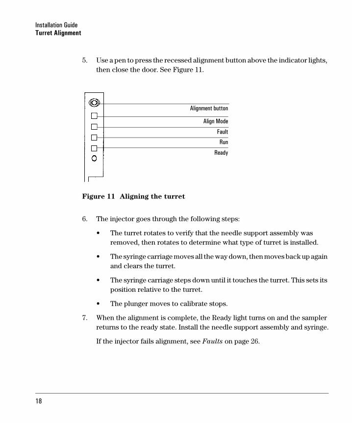
5. Use a pen to press the recessed alignment button above the indicator lights, then close the door. See Figure 11.
Figure 11 Aligning the turret
6. The injector goes through the following steps:
• The turret rotates to verify that the needle support assembly was removed, then rotates to determine what type of turret is installed.
• The syringe carriage moves all the way down, then moves back up again and clears the turret.
• The syringe carriage steps down until it touches the turret. This sets its position relative to the turret.
• The plunger moves to calibrate stops.
7. When the alignment is complete, the Ready light turns on and the sampler returns to the ready state. Install the needle support assembly and syringe.
If the injector fails alignment, see Faults on page 26.
Alignment button
Align Mode
Fault
Run
Ready
18

Installation GuideReplacing The Needle Support Assembly
Replacing The Needle Support Assembly
Use the standard needle support assembly for all injections except cool on-column injections with a 250-µm or 320-µm column. For these injections, you must change the needle support assembly to Agilent accessory 18599T.
Figure 12 Needle support assemblies
To replace the needle support assembly:
1. Remove all vials from turret, and disconnect the injector cable from the GC and lay the G2613A Injector on its back on a flat surface.
2. Open the injector door.
3. Remove the syringe.
530 µm
250 µm/ 320 µm
(standard)(Agilent accessory 18599T)230 µm/ 320 µm Needle support foot Needle support foot
19

Installation GuideReplacing The Needle Support Assembly
Figure 13 Removing the needle support assembly
4. With your finger under the shaft near the bearing on the needle support assembly, pull gently to release the bearing from the bearing clip in the syringe carriage.
5. Carefully use the bearing to pull the rod down until you can lift the assembly out of the syringe carriage.
Caution Be careful not to pull the assembly by its metal shaft. The shaft is easily bent.
Bearing clip
Guide
Syringe
Slide
Bearing
Syringe carriage
Plunger carrier loop
carriagetracks
20

Installation GuideReplacing The Needle Support Assembly
6. To reinstall the needle support assembly, hold it in your right hand and insert the upper end of the rod into the plastic guide to the right of the plunger carrier loop.
7. Turn the needle support assembly so that the flat surface of the slide glides up and down the syringe carriage tracks as shown in Figure 14.
Figure 14 Installing the needle support assembly (250-/320-µm shown)
8. Align the bearing on the needle support assembly with the plastic bearing clip to the right of the syringe latch and push gently on the bearing until the assembly snaps into place.
9. Place the G2613A Injector back on the GC or on a parking post.
Syringe latch
Guide
Syringe
Slide
Slide
Slide
Cross section
Bearing
Bearing clip
of slide alignment
Plunger carrier loop
Syringe carriage
carriagetracks
Syringecarriagetracks
21

Installation GuideReplacing The Needle Guide In The Needle Support Foot
Caution Be careful not to bend the needle during installation.
Caution Do not operate the injector without a syringe in place because the free swinging syringe latch may interfere with the motor.
10. Install the syringe. See your sampler Operation Guide for details.
11. Move the slide up and down to make sure the needle is aligned with the needle guide in the support foot. The needle should slide smoothly in the needle guide.
Replacing The Needle Guide In The Needle Support Foot
When using the Agilent accessory 18599T for 250-/320-µm cool on-column injections, the needle guide is replaceable. Check the needle guide in the needle support foot for wear whenever you change the inlet septum. When the needle guide shows signs of wear, replace it as described below:
1. With an Allen wrench, remove the screw from the needle support foot.
2. Remove the small metal plate from the foot.
3. Replace the needle guide.
4. Replace the metal plate.
5. Replace the screw and tighten.
22

Installation GuideReplacing The Needle Guide In The Needle Support Foot
Figure 15 Needle support foot (250/320-µm assembly shown)
Screw
Metal plate
Needle guide
23
Installation GuideCorrecting Syringe Problems
Correcting Syringe Problems
WARNING When troubleshooting the injector, keep your hands away from the syringe needle. The needle is sharp and may contain hazardous chemicals.
Several things can cause syringe needles to bend. When you find one, check for the following conditions before installing a replacement.
❐ Was the syringe installed properly in the syringe carriage?
❒ Are you using the correct syringe? Is the combined length of the syringe barrel and needle about 126.5 mm? For more information, see your Operation Guide and your Sampling Techniques Handbook.
❒ Are the needle support and needle guide cone clean? Remove any residue or septum deposits. For more information, see Maintenance on page 15.
❒ Is the correct insert for your syringe installed in the cool on-column inlet? For more information, see your GC Operation Manual.
❒ Is the GC septum nut too tight? For more information, see your GC Operation Manual.
❒ Is the septum of the crimp cap centered over the sample vial? For more information, see your Sampling Techniques Handbook.
❒ Are the inside diameters of the sample vial, microvial insert, and vial cap septum at least 5 mm? For more information, see your Operation Guide.
24

Installation GuideCorrecting Sample Vial Delivery Problems
Correcting Sample Vial Delivery Problems
When you find a mishandled sample vial, check:
❒ Are there folds or wrinkles in the crimp cap, especially near the neck of the sample vial? For more information, see your Operation Guide and your Sampling Techniques Handbook.
❒ Are you using the correct sample vials? Is the distance from the vial bottom to the top of the neck about 28.4 mm? Is the bottle neck diameter 8.2 ± 0.3 mm? For more information, see your Operation Guide.
❒ If you use labels on the sample vials, are they the correct size? For more information, see your Operation Guide.
❒ If you use labels on the sample vials, are they interfering with the gripper? For more information, see your Operation Guide.
❒ Are there any obstacles to the tray arm or injector turret motions? Remove any obstacles.
❒ Are the tray quadrants and turret in good condition? Clean any residue from the sample positions. Temperature-controlled liquid pumped through the quadrants, may cause quadrant distortion over time. See your Operation
Guide.
25

Installation GuideFaults
Faults
Four lights on the injector indicate its status.
During normal operation, the Ready light is on. If the injector is busy, the Run light is on.
If another combination of lights are on, an error has occurred.
Use the following instructions to try to solve the problem before obtaining Agilent service.
Figure 16 Injector status lights
Align Mode light
Fault light
Run light
Ready light
26

Installation GuideFaults
No Light Is On
Probable causes
• The line voltage to the GC is off.
• The injector cable or connection to the GC is bad.
• Your GC requires service.
Suggested actions
1. Verify the injector is properly connected to the GC.
2. Check the power source for your GC.
3. Obtain Agilent service.
The Fault Light Is On
Probable cause
The injector door is open.
Suggested actions
1. Ensure that the injector door is closed.
2. If the fault light stays on, obtain Agilent service.
The Fault And The Run Lights Are On
Probable causes
• The injector is mounted incorrectly on the mounting post.
• Incorrect mounting post.
Suggested actions
1. Ensure that the injector is mounted properly. For more information, see page 4.
2. Ensure the correct mounting post is installed. See page 4.
3. If the fault lights stay on, obtain Agilent service.
27

Installation GuideFaults
Align Mode Light Is On
Probable causes
• The turret is not properly installed.
• The type of turret was changed while the power was on.
• The system was not initialized.
• There is an injector memory error.
Suggested action
1. Verify the turret is properly installed. See Removing The Turret on page 16.
2. Perform the alignment procedure to initialize the system. See Turret
Alignment on page 17.
All Lights Are On
Probable causes
• The cables connections are loose.
• There is a board failure.
• There is a firmware revision conflict.
Suggested action
1. Check all cable connections.
2. Turn the instrument off, then on again.
3. If the lights remain on, obtain Agilent service.
28

Installation GuideError Messages
Error Messages
Below is a table of sampler error messages reported on the 6850 and 6890 Plus GC’s. If you receive an error message that is not shown below, record it. Then, make sure that your GC is properly configured and that your sample vials and equipment match your method and/or sequence. If the problem continues, report your error message to Agilent service.
6890 message 6850 message See page
Bottle in gripper – 2
Front (or back) door open or injector not mounted
Inj door or mounting 2
Front (or back) injector com error injector comm error 2
Front (or back) injector incomplete injection Incomplete injection 3
Front (or back) injector reset Injector reset 3
Front (or back) plunger error Plunger error 4
Front (or back) syringe error Syringe error 4
Front (or back) turret error Turret error 5
Injector not present – 5
Injector offline – 6
No bar code reader – 6
No bottle in gripper – 7
Tray not present – 7
Tray offline – 8
– Autoinject aborted 8
– Invalid sequence 8
– No injector 9
– Prerun> 10 min 9
– Sampler error 9
29

Installation GuideError Messages
Bottle In Gripper
Probable cause
The sample vial was not delivered properly and stayed in the tray gripper.
Suggested actions
1. Remove the vial and return it to its position in the tray.
2. Ensure that the tray quadrants are snapped into place.
3. Ensure that the injector is plugged into the correct connector on the back of the 6890 GC and is configured properly. See Configuring Your Gc (6890) on page 12.
4. Check the “deliver to” location for the vial and verify that the location is empty and free from obstructions.
5. Make sure that the injector is upright/vertical on the GC.
6. Restart the sequence.
7. If the error occurs again, obtain Agilent service.
Front (Or Back) Door Open Or Injector Not Mounted
See Faults on page 26.
Front (Or Back) Injector Com Error
Probable cause
There is a communications error between the injector and the GC.
Suggested action
Obtain Agilent service.
30

Installation GuideError Messages
Front (Or Back) Injector Incomplete Injection
Probable causes
• The syringe needle is bent.
• The plunger or syringe carriage is operating incorrectly during injection.
Suggested actions
1. See Correcting Syringe Problems on page 24.
2. Remove the syringe from the injector, and check the plunger for stickiness or binding. Replace the syringe if necessary.
3. Restart the sequence.
4. If the error occurs again, obtain Agilent service.
Front (Or Back) Injector Reset
Probable cause
There is an interruption in the power supply from the GC.
Suggested action
Obtain Agilent service.
31

Installation GuideError Messages
Front (Or Back) Plunger Error
Probable causes
• The syringe plunger is sticking, or not securely connected to the plunger carrier.
• The plunger solenoid is binding.
• The plunger carrier encoder is inoperable.
Suggested actions
1. Remove the syringe, and check it for plunger stickiness or binding. Replace the syringe if necessary. For more information, see Inspecting
a syringe in the Operation Guide.
2. Check the viscosity of the sample against the viscosity parameter. Reset the viscosity parameter if necessary.
3. Restart the sequence.
4. If the error occurs again, obtain Agilent service.
Front (Or Back) Syringe Error
Probable causes
• The syringe carriage motor is defective.
• The syringe is not currently installed or is an incorrect type.
• The syringe carriage sensor is inoperable.
Suggested actions
1. Ensure the syringe is installed correctly. For more information, see your Operation Guide.
2. Ensure the syringe meets specifications.
3. If the syringe needle is bent, see Correcting Syringe Problems on page 24.
32

Installation GuideError Messages
4. Restart the sequence.
5. If the error occurs again, obtain Agilent service.
Front (Or Back) Turret Error
Probable causes
• Something has interfered with the turret rotation.
• The turret motor/encoder assembly is inoperable.
• The turret type was changed while the power was on and the turret alignment procedure was not performed.
• Turret is loose.
Suggested actions
1. Clear any obstructions.
2. Check the Align Mode light. If it is lit, perform the alignment procedure. (See Turret alignment in this section.)
3. Tighten the knurled nut on the top of the turret.
4. If the error occurs again, obtain Agilent service.
Injector Not Present
Probable causes
• There is a board failure in the injector or GC.
• The injector cable is bad or not securely connected to the GC.
• There is a cable failure in the GC.
• Your method specifies an incorrect injector location (method mismatch).
Suggested actions
1. Make sure that the injector to GC cable connection is secure.
33

Installation GuideError Messages
2. Check your method to make sure it uses the appropriate injector location.
3. If the error remains, obtain Agilent service.
Injector Offline
Probable causes
• There is a board failure in the injector or GC.
• The injector cable is bad or not connected.
• There is a cable failure in the GC.
Suggested actions
1. Make sure that the injector to GC cable connection is secure.
2. If the error remains, obtain Agilent service.
No Bar Code Reader
Probable causes
• Bar code reader cable not securely connected.
• Bar code reader is defective.
• Tray is defective.
Suggested actions
1. Ensure the bar code reader cable connection is secure.
2. If the problem continues, obtain Agilent service.
34

Installation GuideError Messages
No Bottle In Gripper
Probable causes
• The sample vial was not found by the gripper.
• The gripper could not grasp the vial.
• The vial was dropped during transfer to or from the turret.
• The sensor in the gripper is defective.
Suggested actions
1. Make sure that the sample vials are in the locations specified by the sequence.
2. Make sure that the sample vials meet recommended specification. See your Sampling Techniques Handbook.
3. If you are using adhesive labels verify that the labels are properly installed. See your Operation Guide.
4. If the error recurs frequently, obtain Agilent service.
Tray Not Present
Probable causes
• There is a board failure in the tray or GC.
• The tray cable is bad or not connected between the GC and tray.
• There is a cable failure in the GC.
Suggested actions
1. Make sure that the tray cable connection is secure.
2. Replace the tray cable.
3. If the error remains, obtain Agilent service.
35

Installation GuideError Messages
Tray Offline
Probable causes
• There is a board failure in the tray or GC.
• The tray cable is bad or not connected.
• There is a cable failure in the GC.
Suggested actions
1. Make sure that the tray to GC cable connection is secure.
2. Replace the tray cable.
3. If the error remains, obtain Agilent service.
Autoinject Aborted
The autoinject sequence on the 6850 was aborted. The other error messages shown on the GC display provide more information on what caused the sequence to abort.
Invalid Sequence
Probable causes
• The sequence is set up for the wrong injection device.
• Hardware required by the sequence is not installed and configured.
• The GC configuration was changed during sequence execution.
• The injector cable is bad or not connected properly.
Suggested actions
1. Make sure that the connection to the GC is secure.
2. Verify the sequence parameters against the GC configuration.
3. If the error remains, obtain Agilent service.
36

Installation GuideError Messages
No Injector
Probable causes
• The cabling connection to the GC became loose during a run.
• An injector board or GC board failed during a run.
Suggested actions
1. Make sure that the connection to the GC is secure.
2. If the error remains, obtain Agilent service.
Prerun > 10 Min
The GC is Not Ready. Check for Not Ready and other GC messages to determine the cause.
Sampler Error
The sampler could not function for an undocumented reason. Record the code number shown in the G2629A Control Module error message. If the problem persists, obtain Agilent service and report the error number.
37

Installation GuideError Messages
38