Agilent 5975/5977 MSD for OpenLAB CDS › cs › library › usermanuals › public ›...
128
Agilent Technologies Agilent 5975/5977 MSD for OpenLAB CDS Operation Manual
Transcript of Agilent 5975/5977 MSD for OpenLAB CDS › cs › library › usermanuals › public ›...
Agilent 5975/5977 MSD for OpenLAB CDS
Operation Manual
Agilent Technologies
2 5975/5977 Series MSD Operation Manual
Notices© Agilent Technologies, Inc. 2015
No part of this manual may be reproduced in
any form or by any means (including elec-
tronic storage and retrieval or translation
into a foreign language) without prior agree-
ment and written consent from Agilent
Technologies, Inc. as governed by United
States and international copyright laws.
Manual Part NumberG7077-90014
EditionFirst edition, August 2015
Printed in USA, August 2015
Agilent Technologies, Inc.
5301 Stevens Creek Boulevard
Santa Clara, CA 95051
WarrantyThe material contained in this docu-ment is provided “as is,” and is sub-ject to being changed, without notice, in future editions. Further, to the max-imum extent permitted by applicable law, Agilent disclaims all warranties, either express or implied, with regard to this manual and any information contained herein, including but not limited to the implied warranties of merchantability and fitness for a par-ticular purpose. Agilent shall not be liable for errors or for incidental or consequential damages in connec-tion with the furnishing, use, or per-formance of this document or of any information contained herein. Should Agilent and the user have a separate written agreement with warranty terms covering the material in this document that conflict with these terms, the warranty terms in the sep-arate agreement shall control.
Safety Notices
CAUTION
A CAUTION notice denotes a
hazard. It calls attention to an
operating procedure, practice, or
the like that, if not correctly
performed or adhered to, could
result in damage to the product or
loss of important data. Do not
proceed beyond a CAUTION notice
until the indicated conditions are
fully understood and met.
WARNING
A WARNING notice denotes a hazard. It calls attention to an operating procedure, practice, or the like that, if not correctly performed or adhered to, could result in personal injury or death. Do not proceed beyond a WARNING notice until the indicated conditions are fully understood and met.
About This Manual
5975/5977 Series MSD Operation M
This manual contains information for operating and maintaining the Agilent 5975 through 5977 series of MSD with OpenLAB CDS software. Agilent OpenLAB CDS is a new operating system for Agilent instruments.
The Agilent 5977B Series Mass Selective Detector (MSD) is the base instrument described in this manual. Agilent instruments manufactured prior to the 5977B share many features and hardware with this new instrument. Where older Agilent models differ from the 5977B, that difference is usually noted. Please refer to the operating and maintenance documentation that was delivered with your instrument if other hardware differences are found.
1
“Introduction”Chapter 1 describes general information about the 5977B Series MSDs, including a hardware description, general safety warnings, and hydrogen safety information.
2
“Installing GC Columns”Chapter 2 shows you how to prepare a capillary column for use with the MSD, install it in the GC oven, and connect it to the MSD using the GC/MSD interface.
3
“Operating in Electron Ionization (EI) Mode”Chapter 3 describes basic tasks such as setting temperatures, monitoring pressures, tuning, venting, and pumpdown. Much of the information in this chapter also applies to CI operation.
4
“General Maintenance”Chapter 4 describes maintenance procedures common to both EI and CI instruments.
anual 3
Hardware User Information
5977B MSD
4
Accompanying your hardware and software, is a comprehensive collection of manuals, videos, user applications, and method development tools. These are located on the Agilent GC and GC/MS User Manuals and Tools DVD set.
See the Agilent 5977B MSD System Quick Start document (G7077-90103) for more details on how to install this information on your computer.
5975/5977 Series MSD prior to the 5977B MSD
Users of Agilent MSD instruments manufactured prior to the 5977B should refer to the documentation delivered to them when their MSD was purchased. The information in this manual is intended to supplement that documentation. Information included here will help you more effectively use the OpenLAB CDS operating system with your instruments.
Additionally, there is extensive online Help and Learning material provided with OpenLAB.
5975/5977 Series MSD Operation Manual
Contents
5975/5977 Series MSD Operation M
About This Manual 3
Hardware User Information 4
5977B MSD 4
5975/5977 Series MSD prior to the 5977B MSD 4
1 Introduction
5977B Series MSD Version 10
Abbreviations Used 11
The 5977B Series MSD 13
MSD Hardware Description 15
Important Safety Warnings 16
Hydrogen Safety 18
GC precautions 18
Precautions 20
Safety and Regulatory Certifications (5977B) 23
Cleaning/Recycling the Product 26
Liquid Spillage 26
Moving or Storing the MSD 26
To Replace the Primary Fuses 27
2 Installing GC Columns
Columns 30
To Install a Capillary Column in a Split/Splitless Inlet 33
To Condition a Capillary Column 36
To Install a Capillary Column in the GC/MS Interface Using the
Self-Tightening Column Nut 37
GCMS transfer line tip seals 41
anual 5
6
To Install a Capillary Column in the GC/MS Interface Using a
Standard Column Nut 42
3 Operating in Electron Ionization (EI) Mode
Operating the MSD from the Data System 46
Operating the MSD from the GC control panel 47
Configuring the MSD through the Web User Interface (WUI) 51
To change the network settings of the MSD 51
Operating the 5975/5977 MSD from the local control panel
(LCP) 54
Modes of operation 54
To view system status during startup 57
eModule mini display readout 61
Front Panel Instrument Status LED 61
The GC/MSD Interface 62
Before You Turn On the MSD 64
Pumping Down 65
Controlling Temperatures 65
Controlling Column Flow 65
Venting the MSD 66
Set MS Analyzer Temperatures 67
Enable the GC/MS Interface and Oven 69
View MSD Temperatures and Vacuum 70
To Calibrate Column Flow Linear Velocity 72
To Run an Autotune 74
To Open the MSD Covers 76
Vent the MSD 77
5975/5977 Series MSD Operation Manual
5975/5977 Series MSD Operation M
To Pump Down the MS 79
To Move or Store the MSD 82
4 General Maintenance
Before Starting 86
Maintaining the Vacuum System 91
Maintaining the Analyzer 92
To Open the Analyzer Chamber 94
To Remove the EI Ion Source 96
To Disassemble the Standard or Inert EI Ion Source 99
To Disassemble the Extractor EI Ion Source 102
To Clean the EI Ion Source 105
To Assemble a Standard or Inert EI Ion Source 110
To Assemble the Extractor EI Ion Source 113
To Replace a Filament in an EI Ion Source 116
To Install the EI Ion Source 118
To Attach Wiring from the Ion Source to the feedthrough
board 119
To Replace the Electron Multiplier Horn 122
To Close the Analyzer Chamber 125
anual 7

8
5975/5977 Series MSD Operation Manual
Agilent 5977B Series Agilent 5975/5977 MSD for OpenLAB CDSOperation Manual
1Introduction
5977B Series MSD Version 10
Abbreviations Used 11
The 5977B Series MSD 13
MSD Hardware Description 15
Important Safety Warnings 16
Hydrogen Safety 18
Safety and Regulatory Certifications (5977B) 23
Cleaning/Recycling the Product 26
Liquid Spillage 26
Moving or Storing the MSD 26
To Replace the Primary Fuses 27
This chapter describes general information about the MSD, including a hardware description, general safety warnings, and hydrogen safety information.
9Agilent Technologies
1 Introduction
5977B Series MSD Version
10
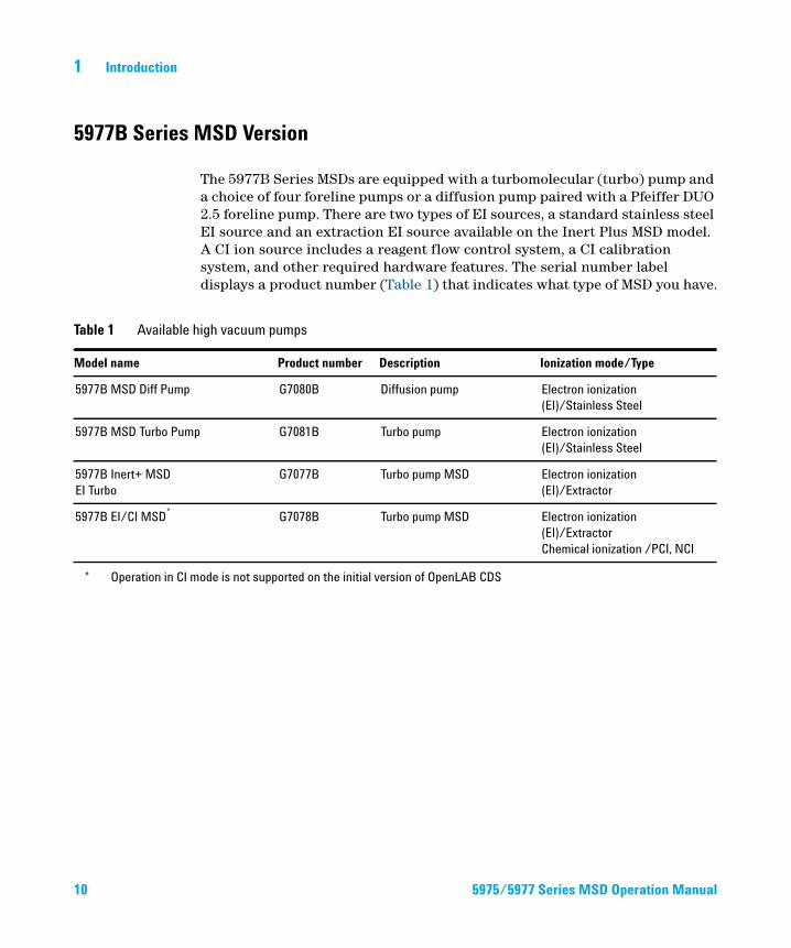
The 5977B Series MSDs are equipped with a turbomolecular (turbo) pump and a choice of four foreline pumps or a diffusion pump paired with a Pfeiffer DUO 2.5 foreline pump. There are two types of EI sources, a standard stainless steel EI source and an extraction EI source available on the Inert Plus MSD model. A CI ion source includes a reagent flow control system, a CI calibration system, and other required hardware features. The serial number label displays a product number (Table 1) that indicates what type of MSD you have.
Table 1 Available high vacuum pumps
Model name Product number Description Ionization mode/Type
5977B MSD Diff Pump G7080B Diffusion pump Electron ionization
(EI)/Stainless Steel
5977B MSD Turbo Pump G7081B Turbo pump Electron ionization
(EI)/Stainless Steel
5977B Inert+ MSD
EI Turbo
G7077B Turbo pump MSD Electron ionization
(EI)/Extractor
5977B EI/CI MSD* G7078B Turbo pump MSD Electron ionization
(EI)/Extractor
Chemical ionization /PCI, NCI
* Operation in CI mode is not supported on the initial version of OpenLAB CDS
5975/5977 Series MSD Operation Manual
Introduction 1
Abbreviations Used
5975/5977 Series M
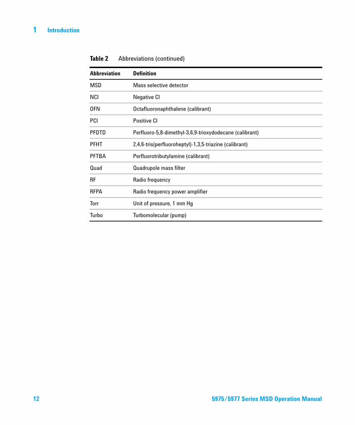
The abbreviations in Table 2 are used in discussing this product. They are collected here for convenience.
Table 2 Abbreviations
Abbreviation Definition
AC Alternating current
ALS Automatic liquid sampler
BFB Bromofluorobenzene (calibrant)
CI Chemical ionization
DC Direct current
DFTPP Decafluorotriphenylphosphine (calibrant)
DIP Direct insertion probe
DS Data System
EI Electron ionization
EM Electron multiplier (detector)
EMV Electron multiplier voltage
EPC Electronic pneumatic control
eV Electron volt
GC Gas chromatograph
HED High-energy dynode (refers to detector and its power supply)
Inert Standard EI source constructed from inert materials
Inert+ Extractor EI source constructed from inert materials
id Inside diameter
LAN Local Area Network
m/z Mass to charge ratio
MFC Mass flow controller
SD Operation Manual 11
12
1 Introduction
MSD Mass selective detector
NCI Negative CI
OFN Octafluoronaphthalene (calibrant)
PCI Positive CI
PFDTD Perfluoro-5,8-dimethyl-3,6,9-trioxydodecane (calibrant)
PFHT 2,4,6-tris(perfluoroheptyl)-1,3,5-triazine (calibrant)
PFTBA Perfluorotributylamine (calibrant)
Quad Quadrupole mass filter
RF Radio frequency
RFPA Radio frequency power amplifier
Torr Unit of pressure, 1 mm Hg
Turbo Turbomolecular (pump)
Table 2 Abbreviations (continued)
Abbreviation Definition
5975/5977 Series MSD Operation Manual
Introduction 1
The 5977B Series MSD
5975/5977 Series M
The 5977B Series MSD is a stand-alone capillary GC detector for use with either an Agilent 7890B Series or an Agilent 7820 Gas Chromatograph. The MSD features:
• WEB User Interface (WUI) for locally monitoring and operating the MSD
• A turbo vacuum pump with one of four different foreline pumps
• A diffusion vacuum pump with a Pfeiffer DUO 2.5 foreline pump
• Three different types of independently heated MSD electron-ionization (EI) sources available: standard source in both stainless steel and inert material, and an extractor source.
• Independently MSD heated hyperbolic quadrupole mass filter
• High-energy dynode (HED) electron multiplier detector
• Independently GC heated GC/MSD interface
Physical description
The 5977B Series MSD housing is approximately 41 cm high, 30 cm wide, and 54 cm deep. The weight is 39 kg for the diffusion pump model, 44 kg for the turbo pump model (EI), and 46 kg for the turbo pump model (EI/CI). The foreline (roughing) pump weighs an additional 11 kg and is usually located on the floor behind the MSD.
The basic components of the instrument are: the frame/cover assemblies, the vacuum system, the GC interface, the electronics, and the analyzer.
SD Operation Manual 13
1 Introduction
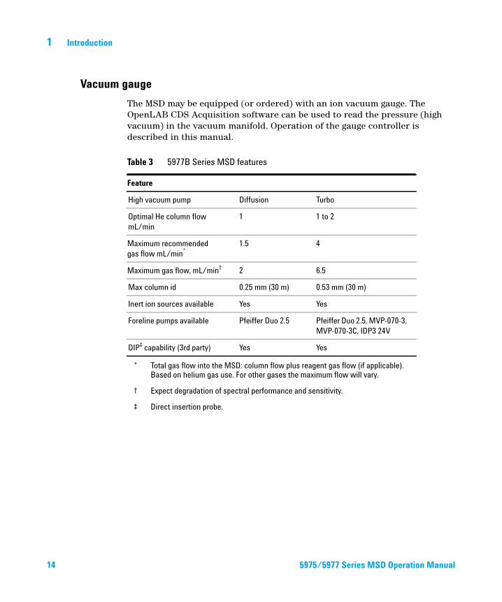
Vacuum gauge
14
The MSD may be equipped (or ordered) with an ion vacuum gauge. The OpenLAB CDS Acquisition software can be used to read the pressure (high vacuum) in the vacuum manifold. Operation of the gauge controller is described in this manual.
Table 3 5977B Series MSD features
Feature
High vacuum pump Diffusion Turbo
Optimal He column flow
mL/min
1 1 to 2
Maximum recommended
gas flow mL/min*
* Total gas flow into the MSD: column flow plus reagent gas flow (if applicable). Based on helium gas use. For other gases the maximum flow will vary.
1.5 4
Maximum gas flow, mL/min†
† Expect degradation of spectral performance and sensitivity.
2 6.5
Max column id 0.25 mm (30 m) 0.53 mm (30 m)
Inert ion sources available Yes Yes
Foreline pumps available Pfeiffer Duo 2.5 Pfeiffer Duo 2.5, MVP-070-3,
MVP-070-3C, IDP3 24V
DIP‡ capability (3rd party)
‡ Direct insertion probe.
Yes Yes
5975/5977 Series MSD Operation Manual
Introduction 1
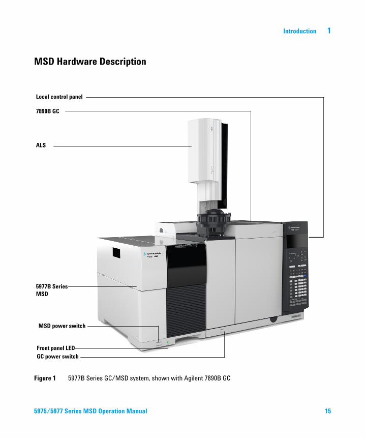
MSD Hardware Description
5975/5977 Series M
Figure 1 5977B Series GC/MSD system, shown with Agilent 7890B GC
ALS
7890B GC
Local control panel
5977B Series MSD
MSD power switch
GC power switchFront panel LED
SD Operation Manual 15
1 Introduction
Important Safety Warnings
16
There are several important safety notices to always keep in mind when using the MSD.
Many internal parts of the MSD carry dangerous voltages
If the MSD is connected to a power source, even if the power switch is off, potentially dangerous voltages exist on:
• The wiring between the MSD power cord and the AC power supply, the AC power supply itself, and the wiring from the AC power supply to the power switch.
With the power switch on, potentially dangerous voltages also exist on:
• All electronics boards in the instrument• The internal wires and cables connected to these boards• The wires for any heater (oven, detector, inlet, or valve box)
All these parts are shielded by covers. With the covers in place, it should be difficult
WARNINGto accidentally make contact with dangerous voltages. Unless specifically instructed to, never remove a cover unless the detector, inlet, or oven are turned off.WARNING If the power cord insulation is frayed or worn, the cord must be replaced. Contact your Agilent service representative.
If one of the primary fuses has failed, the MSD will already be off, but for safety you should switch off the MSD and unplug the power cord. It is not necessary to allow air into the analyzer chamber.
Never replace the primary fuses while the MSD is connected to a power source.
Electrostatic discharge is a threat to MSD electronics
WARNING
The printed circuit boards in the MSD can be damaged by electrostatic discharge. Do not touch any of the boards unless it is absolutely necessary. If you must handle them, wear a grounded wrist strap and take other antistatic precautions.
5975/5977 Series MSD Operation Manual
Introduction 1
Many parts are dangerously hot
5975/5977 Series M
Many parts of the GC/MSD operate at temperatures high enough to cause serious burns. These parts include but are not limited to:
• The GC inlets• The GC oven and its contents including the column nuts attaching the
column to a GC inlet, GC/MS interface, or GC detector• The GC detector • The GC valve box• The foreline pump• The diffusion pump
• The heated MSD ion source, interface, and quadrupole
Always cool these areas of the system to room temperature before working on them. They will cool faster if you first set the temperature of the heated zone to room temperature. Turn the zone off after it has reached the setpoint. If you must perform maintenance on hot parts, use a wrench and wear gloves. Whenever possible, cool the part of the instrument that you will be maintaining before you begin working on it.
Be careful when working behind the instrument. During cool-down cycles, the GC
The oil pan under the standard foreline pump can be a fire hazard
WARNINGemits hot exhaust which can cause burns.
WARNING The insulation around the GC inlets, detectors, valve box, and the insulation cups is made of refractory ceramic fibers. To avoid inhaling fiber particles, we recommend the following safety procedures: ventilate your work area, wear long sleeves, gloves, safety glasses, and a disposable dust/mist respirator; dispose of insulation in a sealed plastic bag; wash your hands with mild soap and cold water after handling the insulation.
Oily rags, paper towels, and similar absorbents in the oil pan could ignite and damage the pump and other parts of the MSD.
WARNING Combustible materials (or flammable/non-flammable wicking material) placed under, over, or around the foreline (roughing) pump constitutes a fire hazard. Keep the pan clean, and do not leave absorbent material such as paper towels in it.
SD Operation Manual 17
1 Introduction
Hydrogen Safety
18
WARNING Using hydrogen as a GC carrier gas is potentially dangerous.
WARNING When using hydrogen (H2) as the carrier gas or fuel gas, be aware that hydrogen can flow into the GC oven and create an explosion hazard. Therefore, be sure that the supply is turned off until all connections are made and ensure that the inlet and detector column fittings are either connected to a column or capped at all times when hydrogen is supplied to the instrument.
Hydrogen is flammable. Leaks, when confined in an enclosed space, may create a fire or explosion hazard. In any application using hydrogen, leak test all connections, lines, and valves before operating the instrument. Always turn off the hydrogen supply at its source before working on the instrument.
Hydrogen is a commonly used GC carrier gas. Hydrogen is potentially explosive and has other dangerous characteristics:
• Hydrogen is combustible over a wide range of concentrations. At atmospheric pressure, hydrogen is combustible at concentrations from 4% to 74.2% by volume.
• Hydrogen has the highest burning velocity of any gas.
• Hydrogen has a very low ignition energy.
• Hydrogen that is allowed to expand rapidly from high pressure can self-ignite.
• Hydrogen burns with a non luminous flame which can be invisible under bright light.
GC precautions
When using hydrogen as a carrier gas, remove the large round plastic cover for the MSD transfer line located on the GC left side panel. In the unlikely event of an explosion, this cover may dislodge.
5975/5977 Series MSD Operation Manual
Introduction 1
Dangers unique to GC/MSD operation
5975/5977 Series M
Hydrogen presents a number of dangers. Some are general, others are unique to GC or GC/MSD operation. Dangers include, but are not limited to:
• Combustion of leaking hydrogen
• Combustion due to rapid expansion of hydrogen from a high-pressure cylinder
• Accumulation of hydrogen in the GC oven and subsequent combustion (see your GC documentation and the label on the top edge of the GC oven door)
• Accumulation of hydrogen in the MSD and subsequent combustion
Hydrogen accumulation in an MSD
WARNING The MSD cannot detect leaks in inlet and/or detector gas streams. For this reason, it is vital that column fittings should always be either connected to a column or have a cap or plug installed.
All users should be aware of the mechanisms by which hydrogen can accumulate (Table 4 on page 19) and know what precautions to take if they know or suspect that hydrogen has accumulated. Note that these mechanisms apply to all mass spectrometers, including the MSD.
Table 4 Hydrogen accumulation mechanisms
Mechanism Results
Mass spectrometer turned off A mass spectrometer can be shut down deliberately. It can
also be shut down accidentally by an internal or external
failure. There is a safety feature that will shut down the flow
of carrier gas in the event of an MSD foreline pump shut
down. However, if this feature fails, hydrogen may slowly
accumulate in the mass spectrometer.
Mass spectrometer automated
shutoff valves closed
Some mass spectrometers are equipped with automated
diffusion pump shutoff valves. In these instruments,
deliberate operator action or various failures can cause the
shutoff valves to close. Shutoff valve closure does not shut
off the flow of carrier gas. As a result, hydrogen may slowly
accumulate in the mass spectrometer.
SD Operation Manual 19
20
1 Introduction
Mass spectrometer manual shutoff
valves closed
Some mass spectrometers are equipped with manual
diffusion pump shutoff valves. In these instruments, the
operator can close the shutoff valves. Closing the shutoff
valves does not shut off the flow of carrier gas. As a result,
hydrogen may slowly accumulate in the mass spectrometer.
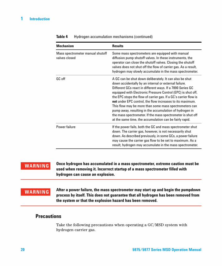
GC off A GC can be shut down deliberately. It can also be shut
down accidentally by an internal or external failure.
Different GCs react in different ways. If a 7890 Series GC
equipped with Electronic Pressure Control (EPC) is shut off,
the EPC stops the flow of carrier gas. If a GC’s carrier flow is
not under EPC control, the flow increases to its maximum.
This flow may be more than some mass spectrometers can
pump away, resulting in the accumulation of hydrogen in
the mass spectrometer. If the mass spectrometer is shut off
at the same time, the accumulation can be fairly rapid.
Power failure If the power fails, both the GC and mass spectrometer shut
down. The carrier gas, however, is not necessarily shut
down. As described previously, in some GCs, a power failure
may cause the carrier gas flow to be set to maximum. As a
result, hydrogen may accumulate in the mass spectrometer.
Table 4 Hydrogen accumulation mechanisms (continued)
Mechanism Results
Precautions
WARNING Once hydrogen has accumulated in a mass spectrometer, extreme caution must be used when removing it. Incorrect startup of a mass spectrometer filled with hydrogen can cause an explosion.
WARNING After a power failure, the mass spectrometer may start up and begin the pumpdown process by itself. This does not guarantee that all hydrogen has been removed from the system or that the explosion hazard has been removed.
Take the following precautions when operating a GC/MSD system with hydrogen carrier gas.
5975/5977 Series MSD Operation Manual
Introduction 1
5975/5977 Series M
Equipment precaution
You MUST make sure the front side-plate thumbscrew is fastened finger-tight. Do not overtighten the thumbscrew; it can cause air leaks.
WARNING Failure to secure your MSD as described above greatly increases the chance of personal injury in the event of an explosion.
You must remove the plastic cover over the glass window on the front of a 5977B Series MSD. In the unlikely event of an explosion, this cover may dislodge.
General laboratory precautions
• Avoid leaks in the carrier gas lines. Use leak-checking equipment to periodically check for hydrogen leaks.
• Eliminate from your laboratory as many ignition sources as possible (open flames, devices that can spark, sources of static electricity, etc.).
• Do not allow hydrogen from a high pressure cylinder to vent directly to atmosphere (danger of self-ignition).
• Use a hydrogen generator instead of bottled hydrogen.
Operating precautions
• Turn off the hydrogen at its source every time you shut down the GC or MSD.
• Turn off the hydrogen at its source every time you vent the MSD (do not heat the capillary column without carrier gas flow).
• Turn off the hydrogen at its source every time shutoff valves in an MSD are closed (do not heat the capillary column without carrier gas flow).
• Turn off the hydrogen at its source if a power failure occurs.
• If a power failure occurs while the GC/MSD system is unattended, even if the system has restarted by itself:
1 Immediately turn off the hydrogen at its source.
2 Turn off the GC.
3 Turn off the MSD and allow it to cool for 1 hour.
SD Operation Manual 21
22
1 Introduction
4 Eliminate all potential sources of ignition in the room.
5 Open the vacuum manifold of the MSD to atmosphere.
6 Wait at least 10 minutes to allow any hydrogen to dissipate.
7 Start up the GC and MSD as normal.
When using hydrogencheck the system for leaks to prevent possible fire and explosion hazards based on local Environmental Health and Safety (EHS) requirements. Always check for leaks after changing a tank or servicing the gas lines. Always make sure the foreline pump exhaust and GC injection port vents are both vented into a fume hood.
5975/5977 Series MSD Operation Manual
Introduction 1
Safety and Regulatory Certifications (5977B)
5975/5977 Series M
For models other than the 5977B, see the documentation that was delivered with your MSD for these certifications.
The 5977B Series MSD conforms to the following safety standards:
• Canadian Standards Association (CSA): CAN/CSA-C222 No. 61010-1-04
• CSA/Nationally Recognized Test Laboratory (NRTL): UL 61010–1
• International Electrotechnical Commission (IEC): 61010–1
• EuroNorm (EN): 61010–1
The 5977B Series MSD conforms to the following regulations on Electromagnetic Compatibility (EMC) and Radio Frequency Interference (RFI):
• CISPR 11/EN 55011: Group 1, Class A
• IEC/EN 61326
• AUS/NZ
This ISM device complies with Canadian ICES-001. Cet appareil ISM est conforme a la norme NMB—001 du Canada.
The 5977B Series MSD is designed and manufactured under a quality system registered to ISO 9001.
The 5977B Series MSD is RoHS compliant.
Information
The Agilent Technologies 5977B Series MSD meets the following IEC (International Electro-technical Commission) classifications: Equipment Class I, Laboratory Equipment, Installation Category II, Pollution Degree 2.
This unit has been designed and tested in accordance with recognized safety standards and is designed for use indoors. If the instrument is used in a manner not specified by the manufacturer, the protection provided by the instrument may be impaired. Whenever the safety protection of the MSD has been compromised, disconnect the unit from all power sources and secure the unit against unintended operation.
SD Operation Manual 23
24
1 Introduction
Refer servicing to qualified service personnel. Substituting parts or performing any unauthorized modification to the instrument may result in a safety hazard.
Symbols
Warnings in the manual or on the instrument must be observed during all phases of operation, service, and repair of this instrument. Failure to comply with these precautions violates safety standards of design and the intended use of the instrument. Agilent Technologies assumes no liability for the customer’s failure to comply with these requirements.
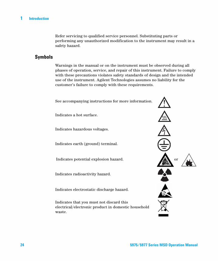
See accompanying instructions for more information.
Indicates a hot surface.
Indicates hazardous voltages.
Indicates earth (ground) terminal.
Indicates potential explosion hazard.
Indicates radioactivity hazard.
Indicates electrostatic discharge hazard.
Indicates that you must not discard this electrical/electronic product in domestic household waste.
or
5975/5977 Series MSD Operation Manual
Introduction 1
Electromagnetic compatibility
5975/5977 Series M
This device complies with the requirements of CISPR 11. Operation is subject to the following two conditions:
• This device may not cause harmful interference.
• This device must accept any interference received, including interference that may cause undesired operation.
If this equipment does cause harmful interference to radio or television reception, which can be determined by turning the equipment on and off, the user is encouraged to try one or more of the following measures:
1 Relocate the radio or antenna.
2 Move the device away from the radio or television.
3 Plug the device into a different electrical outlet, so that the device and the radio or television are on separate electrical circuits.
4 Ensure that all peripheral devices are also certified.
5 Ensure that appropriate cables are used to connect the device to peripheral equipment.
6 Consult your equipment dealer, Agilent Technologies, or an experienced technician for assistance.
7 Changes or modifications not expressly approved by Agilent Technologies could void the user’s authority to operate the equipment.
Sound emission declaration
Sound pressure
Sound pressure Lp <70 dB according to EN 27779:1991.
Sound pressure Lp <70 dB according to EN ISO 3744:1995 (5977B only)
SD Operation Manual 25
1 Introduction
Cleaning/Recycling the Product
26
To clean the unit, disconnect the power and wipe down with a damp, lint-free cloth. For recycling, contact your local Agilent sales office.
Liquid Spillage
Do not spill liquids on the MSD.
Moving or Storing the MSD
The best way to keep your MSD functioning properly is to keep it pumped down and hot, with carrier gas flow. If you plan to move or store your MSD, a few additional precautions are required. The MSD must remain upright at all times; this requires special caution when moving. The MSD should not be left vented to atmosphere for long periods.
5975/5977 Series MSD Operation Manual

Introduction 1
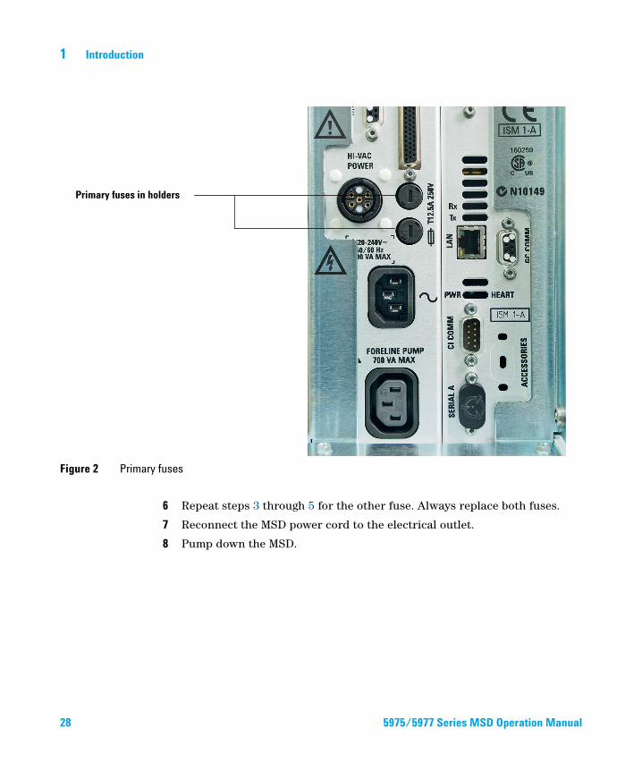
To Replace the Primary Fuses
5975/5977 Series M
Materials needed
• Fuse, T12.5A, 250 V (2110-1398) – 2 required
• Screwdriver, flat-blade (8730-0002)
The most likely cause of failure of the primary fuses is a problem with the foreline pump. If the primary fuses in your MSD fail, check the foreline pump.
Procedure
1 Vent the MSD and unplug the power cord from the electrical outlet.
If one of the primary fuses has failed, the MSD will already be off, but for safety you should switch off the MSD and unplug the power cord. It is not necessary to allow air into the analyzer chamber.
WARNING Never replace the primary fuses while the MSD is connected to a power source.
WARNING If you are using hydrogen as a GC carrier gas, a power failure may allow it to accumulate in the analyzer chamber. In that case, further precautions are required. See “Hydrogen Safety” on page 18.
2 Turn one of the fuse holders (Figure 2 on page 28) counterclockwise until it pops out. The fuse holders are spring loaded.
3 Remove the old fuse from the fuse holder.
4 Install a new fuse in the fuse holder.
5 Reinstall the fuse holder.
SD Operation Manual 27
28
1 Introduction
Figure 2 Primary fuses
Primary fuses in holders
6 Repeat steps 3 through 5 for the other fuse. Always replace both fuses.
7 Reconnect the MSD power cord to the electrical outlet.
8 Pump down the MSD.
5975/5977 Series MSD Operation Manual
Agilent 5977B Series MSDOperation Manual
2Installing GC Columns
Columns 30
To Install a Capillary Column in a Split/Splitless Inlet 33
To Condition a Capillary Column 36
To Install a Capillary Column in the GC/MS Interface Using the
Self-Tightening Column Nut 37
To Install a Capillary Column in the GC/MS Interface Using a Standard
Column Nut 42
Before you can operate your GC/MSD system, you must select, install, and condition a GC column. This chapter shows you how to install and condition a column. For correct column and flow selection, you must know what type of vacuum system your MSD has.
29Agilent Technologies
2 Installing GC Columns
Columns
30
Many types of GC columns can be used with the MSD but there are some restrictions.
During tuning or data acquisition, the rate of column flow into the MSD should not exceed the maximum recommended flow. Therefore, there are limits to column length, diameter, and flow. Exceeding recommended flow results in degradation of mass spectral and sensitivity performance.
Remember that column flows vary greatly with oven temperature. See “To Calibrate Column Flow Linear Velocity” on page 72 for instructions on how to measure actual flow in your column.Use the Flow Calculation software and Table 5 to determine whether a given column will give acceptable flow with realistic head pressure.
Table 5 Gas flows
Feature
High vacuum pump Diffusion Turbo
Optimal He column flow mL/min 1 1 to 2
Maximum recommended gas flow mL/min*
* Total gas flow into the MSD: column flow plus reagent gas flow (if applicable). Based on helium gas use. For other gases the maximum flow will vary.
1.5 4
Maximum gas flow, mL/min†
† Expect degradation of spectral performance and sensitivity.
2 6.5
Max column id 0.53 mm
(30 m)
0.53 mm
(30 m)
CI capability‡
‡ Operation in CI mode is not supported on the initial version of OpenLAB CDS.
No Yes
5977B Series MSD Operation Manual
Installing GC Columns 2
Conditioning columns
5977B Series MSD O
Conditioning a column before it is connected to the GC/MSD interface is essential. See “To Condition a Capillary Column” on page 36.
A small portion of the capillary column stationary phase is often carried away by the carrier gas. This is called column bleed. Column bleed deposits traces of the stationary phase in the MSD ion source. This decreases MSD sensitivity and makes cleaning the ion source necessary.
Column bleed is most common in new or poorly crosslinked columns. It is much worse if there are traces of oxygen in the carrier gas when the column is heated. To minimize column bleed, all capillary columns should be conditioned before they are installed in the GC/MSD interface.
Conditioning ferrules
Heating ferrules to their maximum expected operating temperature a few times before they are installed can reduce chemical bleed from the ferrules. Thermal cycling ferrules to their maximum operating temperatures, prior to running your application, will help reduce leaks from the assembly.
Tips and hints
• The column installation procedures for the 5977B Series MSDs may be different from that for previous MSDs. Using the procedure from another instrument may not work and may damage the column or the MSD.
• Always use carrier gas that is at least 99.9995% pure.
• Because of thermal expansion, new ferrules may loosen after heating and cooling a few times. Check for tightness after two or three heating cycles or use the self tightening column nuts.
• Always wear clean gloves when handling columns, especially the end that will be inserted into the GC/MSD interface.
If you are using hydrogen as a carrier gas, do not start carrier gas flow until the
WARNINGcolumn is installed in the MSD and the MSD has been pumped down. If the vacuum pumps are off, hydrogen will accumulate in the MSD and an explosion may occur. See “Hydrogen Safety” on page 18.peration Manual 31

2 Installing GC Columns
WARNING Always wear safety glasses when handling capillary columns. Use care to avoid puncturing your skin with the end of the column.
32 5977B Series MSD Operation Manual
Installing GC Columns 2
To Install a Capillary Column in a Split/Splitless Inlet
5977B Series MSD O
Materials needed
• Gloves, clean
• Large (8650-0030)
• Small (8650-0029)
• Metric ruler
• Wrench, open-end, 1/4-inch and 5/16-inch (8710-0510)
• Capillary column
• Column cutter, ceramic (5181-8836) or diamond (5183-4620)
• Ferrules
• 0.27-mm id, for 0.10-mm id columns (5062-3518)
• 0.37-mm id, for 0.20-mm id columns (5062-3516)
• 0.40-mm id, for 0.25-mm id columns (5181-3323)
• 0.5-mm id, for 0.32-mm id columns (5062-3514)
• 0.8-mm id, for 0.53-mm id columns (5062-3512)
• Inlet column nut (5181-8830 for Agilent 7890 Series and 7820)
• Magnifying loupe
• Septum (may be old, used inlet septum)
To install columns in other types of inlets, refer to your Gas Chromatograph User Information.
WARNING The GC operates at high temperatures. In order to avoid burns, do not touch any parts of the GC until you are sure they are cool.
WARNING Always wear safety glasses when handling capillary columns. Use care to avoid puncturing your skin with the end of the column.
peration Manual 33
2 Installing GC Columns
CAUTION Always wear clean gloves while handling any parts that go inside the GC or analyzer
chambers.
34
Procedure
1 Cool the oven and inlet to room temperature.
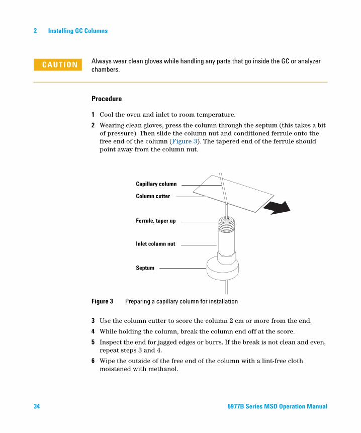
2 Wearing clean gloves, press the column through the septum (this takes a bit of pressure). Then slide the column nut and conditioned ferrule onto the free end of the column (Figure 3). The tapered end of the ferrule should point away from the column nut.
3 Use the column cutter to score the column 2 cm or more from the end.
4 While holding the column, break the column end off at the score.
5 Inspect the end for jagged edges or burrs. If the break is not clean and even, repeat steps 3 and 4.
6 Wipe the outside of the free end of the column with a lint-free cloth moistened with methanol.
Figure 3 Preparing a capillary column for installation
Capillary column
Column cutter
Ferrule, taper up
Inlet column nut
Septum
5977B Series MSD Operation Manual

Installing GC Columns 2
5977B Series MSD O
7 Position the column so it extends 4 to 6 mm past the end of the ferrule (Figure 4).
8 Slide the septum up to the bottom of the nut to fix the correct column insertion length.
9 Insert the column in the inlet.
10 Slide the nut up the column to the inlet base and finger-tighten the nut.
11 Adjust the column position so the septum is even with the bottom of the column nut.
12 Tighten the column nut an additional 1/4 to 1/2 turn. The column should not slide with a gentle tug.
13 Start carrier gas flow.
14 Verify flow by submerging the free end of the column in isopropanol. Look for bubbles.
See also
For more information about installing a capillary column, refer to Optimizing Splitless Injections on Your GC for High Performance MS Analysis, Agilent Technologies publication number 5988-9944EN.
Figure 4 Installing a capillary column for a split/splitless inlet
Insulation cup
Reducing nut
Capillary column
Ferrule (inside nut)
Inlet column nut
Septum
4 to 6 mm
peration Manual
35
2 Installing GC Columns
To Condition a Capillary Column
36
Materials needed
• Carrier gas, (99.9995% pure or better)
• Wrench, open-end, 1/4-inch and 5/16-inch (8710-0510)
WARNING Do not condition your capillary column with hydrogen. Hydrogen accumulation in the GC oven can result in an explosion. If you plan to use hydrogen as your carrier gas, first condition the column with ultrapure (99.999% or better) inert gas such as helium, nitrogen, or argon.
WARNING The GC operates under high temperatures. To avoid burns, do not touch any GC parts unless you are certain they are cool.
Procedure
1 Install the column in the GC inlet. (See “To Install a Capillary Column in a Split/Splitless Inlet” on page 33.)
2 Set a minimum velocity of 30 cm/s, or as recommended by the column manufacturer. Allow the carrier gas to flow through the column at room temperature for 15 to 30 minutes to remove air.
3 Program the oven from room temperature to the maximum temperature limit for the column.
4 Increase the temperature at a rate of 10 to 15 °C/min.
5 Hold at the maximum temperature for 30 minutes.
CAUTION Never exceed the maximum column temperature, either in the GC/MS interface, the
GC oven, or the inlet.
6 Set the GC oven temperature to 30 °C and wait for the GC to become ready.
7 Attach the column to the GC interface. (See “To Install a Capillary Column in the GC/MS Interface Using the Self-Tightening Column Nut” on page 37.)
5977B Series MSD Operation Manual
Installing GC Columns 2
To Install a Capillary Column in the GC/MS Interface Using the Self-Tightening Column Nut
5977B Series MSD O
This procedure is for the installation of a capillary column directly into the analyzer using the Agilent recommended self-tightening column nut.
Materials needed
For the GCMS transfer line tip seals required for models with CI and extraction ion sources see “GCMS transfer line tip seals” on page 41.
• Column cutter, ceramic (5181-8836) or diamond (5183-4620)
• Flashlight
• Magnifying loupe
• Gloves, clean
• Large (8650-0030)
• Small (8650-0029)
• Self Tightening column nut for GC\MS interface (5190-5233)
• Ferrules, Vespel
• 0.27 mm id, for 0.10 mm id columns (5062-3518)
• 0.37 mm id, for 0.20 mm id columns (5062-3516)
• 0.40 mm id, for 0.25 mm id columns (5181-3323)
• 0.5 mm id, for 0.32 mm id columns (5062-3514)
• 0.8 mm id, for 0.53 mm id columns (5062-3512)
• Septum (may be old, used inlet septum)
• Safety glasses
Always wear clean gloves while handling any parts that go inside the GC or the
CAUTIONanalyzer chambers.peration Manual 37
2 Installing GC Columns
38
Procedure
1 Condition the column. (See “To Condition a Capillary Column” on page 36.)
The analyzer, GC/MS interface, and other components in the analyzer chamber
WARNINGoperate at very high temperatures. Do not touch any part until you are sure it is cool.WARNING Dangerous voltages exist inside the analyzer chamber, which can result in fatal injury. Do not open the analyzer chamber door for any reason. If access is ever required, trained service personnel must first disconnect the instrument from the building power source.
2 If you are not using Quick Swap, vent the MS. To vent the MS, see “Vent the MSD” on page 77.
The GC operates under high temperatures. To avoid burns, do not touch any GC parts
WARNINGuntil you are certain they are cool.3 Slide an interface nut and conditioned ferrule onto the free end of the GC column. The tapered end of the ferrule must point towards the nut.
4 Use the column cutter to score the column 2 cm from its end.
5 While holding the column against the column cutter with your thumb, break the column against the edge of the column cutter.
6 Inspect the end for jagged edges or burrs. If the break is not clean and even, repeat steps 4 and 5.
7 Wipe the end with alcohol.
5977B Series MSD Operation Manual
Installing GC Columns 2
5977B Series MSD O
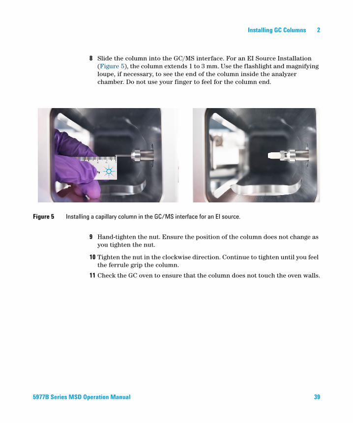
8 Slide the column into the GC/MS interface. For an EI Source Installation (Figure 5), the column extends 1 to 3 mm. Use the flashlight and magnifying loupe, if necessary, to see the end of the column inside the analyzer chamber. Do not use your finger to feel for the column end.
Figure 5 Installing a capillary column in the GC/MS interface for an EI source.
9 Hand-tighten the nut. Ensure the position of the column does not change as you tighten the nut.
10 Tighten the nut in the clockwise direction. Continue to tighten until you feel the ferrule grip the column.
11 Check the GC oven to ensure that the column does not touch the oven walls.
peration Manual 39
2 Installing GC Columns
40
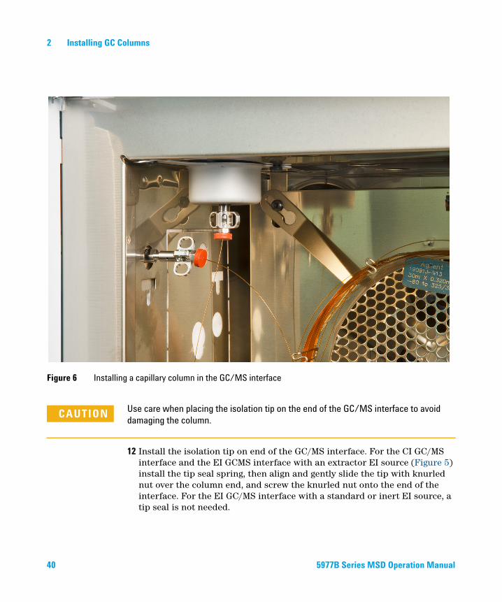
Figure 6 Installing a capillary column in the GC/MS interface
Use care when placing the isolation tip on the end of the GC/MS interface to avoid
CAUTIONdamaging the column.12 Install the isolation tip on end of the GC/MS interface. For the CI GC/MS interface and the EI GCMS interface with an extractor EI source (Figure 5) install the tip seal spring, then align and gently slide the tip with knurled nut over the column end, and screw the knurled nut onto the end of the interface. For the EI GC/MS interface with a standard or inert EI source, a tip seal is not needed.
5977B Series MSD Operation Manual
Installing GC Columns 2
5977B Series MSD O
13 Gently check the alignment of the ion source and the interface tip seal.
When the ion source is aligned correctly, the front analyzer chamber can be closed all the way with no resistance except the spring tension from the interface tip seal.
CAUTION Forcing the analyzer door closed if these parts are misaligned will damage the seal or
the interface or the ion source, or will keep the sideplate from sealing.
14 You can align the ion source and interface tip seal by wiggling the side plate on its hinge. If the door still will not close, contact your Agilent Technologies service representative.
15 Close the analyzer chamber door. (See “To Close the Analyzer Chamber” on page 125.)
GCMS transfer line tip seals
Table 6 EI GCMS interface transfer line tip seal for extractor ion sources
Model 5977A 5977B
Tip seal G3870-20542 G3870-20542
Spring G7005-20024 G1999-20023
Tip cap G3870-20543 G3870-20547
Tip base ------------------ G3870-20548
Table 7 CI GCMS transfer line tip seals for CI and extraction ion sources
Model 5975 5977A 5977B
Tip seal G1099-60412 G1999-60412 G1999-60412
Tip cap ----------------- G3870-20543 G3870-20547
Tip base ----------------- ------------------ G3870-20548
peration Manual 41
2 Installing GC Columns
To Install a Capillary Column in the GC/MS Interface Using a Standard Column Nut
42
This procedure is for the installation of a capillary column directly into the analyzer. There are two types of column nuts that can be used in the GC/MS interface: The standard column nut explained here, and the self tightening column nut explained in the next section.
Materials needed
For the GCMS transfer line tip seals required for models with CI and extraction ion sources see “GCMS transfer line tip seals” on page 41.
• Column cutter, ceramic (5181-8836) or diamond (5183-4620)
• Flashlight
• Magnifying loupe
• Gloves, clean
• Large (8650-0030)
• Small (8650-0029)
• Interface column nut (05988-20066)
• Ferrules
• 0.3 mm id, for 0.10 mm id columns (5062-3507)
• 0.4 mm id, for 0.20 and 0.25 mm id columns (5062-3508)
• 0.5 mm id, for 0.32 mm id columns (5062-3506)
• 0.8 mm id, for 0.53 mm id columns (5062-3512)
• Septum (may be old, used inlet septum)
• Safety glasses
• Wrench, open-end, 1/4-inch and 5/16-inch (8710-0510)
5977B Series MSD Operation Manual
Installing GC Columns 2
5977B Series MSD O
Procedure
Always wear clean gloves while handling any parts that go inside the GC or the
CAUTIONanalyzer chambers.The analyzer, GC/MS interface, and other components in the analyzer chamber
WARNINGoperate at very high temperatures. Do not touch any part until you are sure it is cool.1 Condition the column. (See “To Condition a Capillary Column” on page 36.)
2 Vent the MS (See “Vent the MSD” on page 77) and open the front analyzer chamber (See “To Open the Analyzer Chamber” on page 94). Be sure you can see the end of the GC/MS interface.
The GC operates under high temperatures. To avoid burns, do not touch any GC parts
WARNINGunless you are certain they are cool.3 Slide an interface nut and conditioned ferrule onto the free end of the GC column. The tapered end of the ferrule must point towards the nut.
4 Use the column cutter to score the column 2 cm from the end.
5 While holding the column against the column cutter with your thumb, break the column against the edge of the column cutter.
6 Inspect the end for jagged edges or burrs. If the break is not clean and even, repeat steps 5 and 6.
7 Slide the column into the GC/MS interface. For an EI Source Installation (Figure 5), the column extends 1 to 3 mm. Use the flashlight and magnifying loupe if necessary to see the end of the column inside the analyzer chamber. Do not use your finger to feel for the column end.
8 Hand-tighten the nut. Ensure the position of the column does not change as you tighten the nut, and be sure to not over tighten the nut.
9 Check the GC oven to be sure that the column does not touch the oven walls.
peration Manual 43
2 Installing GC Columns
44
10 Tighten the nut 1/4 to 1/2 turn.
11 Check the nut’s tightness after one or two heat cycles; tighten additionally as appropriate.
CAUTION Use care when placing the isolation tip on the end of the GC/MS interface to avoid
damaging the column.
12 Install the isolation tip on end of the GC/MS interface. For the EI GC/MS interface with a standard or inert EI source, a tip seal is not needed.
13 Gently check the alignment of the ion source and the interface tip seal.
When the ion source is aligned correctly, the front analyzer chamber can be closed all the way with no resistance except the spring tension from the interface tip seal.
CAUTION Forcing the analyzer door closed if these parts are misaligned will damage the seal or
the interface or the ion source, or will keep the sideplate from sealing.
14 You can align the ion source and interface tip seal by wiggling the side plate on its hinge. If the door still will not close, contact your Agilent Technologies service representative.
15 Close the analyzer chamber door. (See “To Close the Analyzer Chamber” on page 125.)
5977B Series MSD Operation Manual
Agilent 5977B Series Agilent 5975/5977 MSD for OpenLAB CDSOperation Manual
3Operating in Electron Ionization (EI) Mode
Operating the MSD from the Data System 46
Operating the MSD from the GC control panel 47
Configuring the MSD through the Web User Interface (WUI) 51
Operating the 5975/5977 MSD from the local control panel (LCP) 54
eModule mini display readout 61
Front Panel Instrument Status LED 61
The GC/MSD Interface 62
Before You Turn On the MSD 64
Pumping Down 65
Controlling Temperatures 65
Controlling Column Flow 65
Venting the MSD 66
Set MS Analyzer Temperatures 67
Enable the GC/MS Interface and Oven 69
View MSD Temperatures and Vacuum 70
To Calibrate Column Flow Linear Velocity 72
To Run an Autotune 74
To Open the MSD Covers 76
Vent the MSD 77
To Pump Down the MS 79
To Move or Store the MSD 82
This chapter describes how to perform some basic operating procedures for the Agilent 5975/5977 series GC/MSD using electron ionization.
45Agilent Technologies
3 Operating in Electron Ionization (EI) Mode
Operating the MSD from the Data System
46
The Agilent OpenLAB CDS software automates tasks such as pumping down, monitoring settings, setting temperatures, tuning, and venting the MSD. These tasks are described in this chapter. Additional information is described in the manuals and online help supplied with the OpenLAB CDS software.
CAUTION The software and firmware are revised periodically. If the steps in these procedures do
not match your OpenLAB CDS, refer to the manuals and online help supplied with the
software for more information.
5975/5977 Series MSD Operation Manual
Operating in Electron Ionization (EI) Mode 3
Operating the MSD from the GC control panel
5975/5977 Series M
This section only applies to the 5977B MSD. For earlier 5975/5977 MSD models, refer to “Operating the 5975/5977 MSD from the local control panel (LCP)”on page 54.
The 7890B GC control panel can show the actual temperature and pressure of the MSD or initiate a task on the MSD without using the Agilent OpenLAB CDS software. You can access functions, such as venting and setting temperatures, right from the GC control panel. Limited features are available from the GC control panel. The OpenLAB CDS software is the full-featured controller for most instrument control operations.
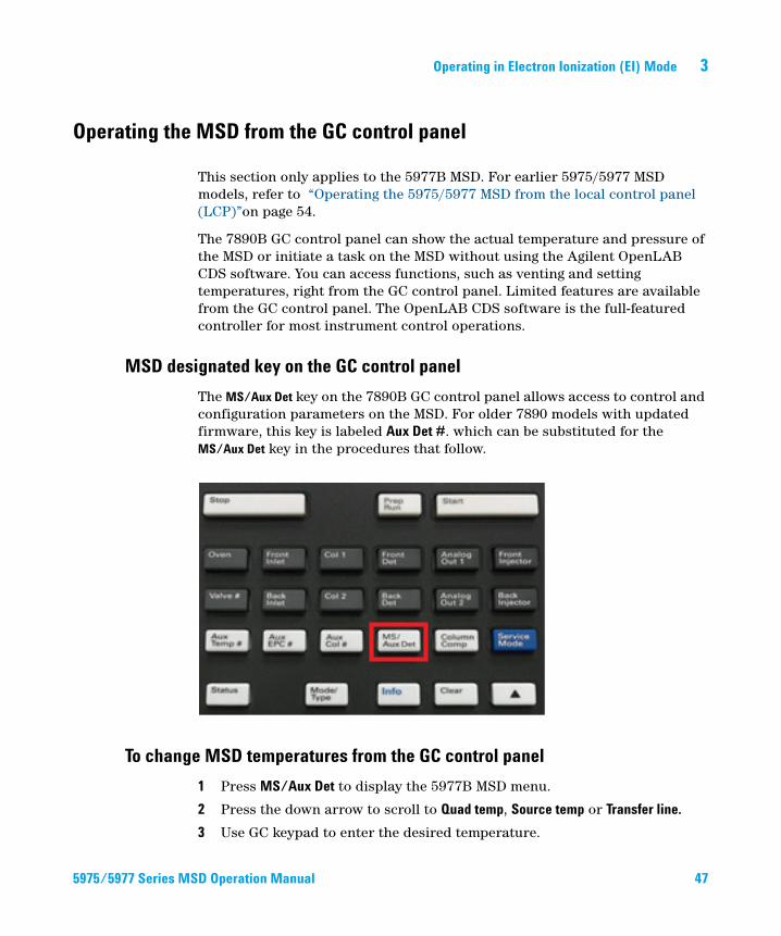
MSD designated key on the GC control panel
The MS/Aux Det key on the 7890B GC control panel allows access to control and configuration parameters on the MSD. For older 7890 models with updated firmware, this key is labeled Aux Det #. which can be substituted for the MS/Aux Det key in the procedures that follow.
To change MSD temperatures from the GC control panel
1 Press MS/Aux Det to display the 5977B MSD menu.
2 Press the down arrow to scroll to Quad temp, Source temp or Transfer line.
3 Use GC keypad to enter the desired temperature.
SD Operation Manual 47

48
3 Operating in Electron Ionization (EI) Mode
4 Press Enter to apply the changes.
To view MSD vacuum pressure and Turbo speed/Foreline Pressure from the GC control panel
1 Press MS/Aux Det to display the 5977B MSD menu.
2 Press the down arrow to scroll to HiVac Pressure, or Turbo Speed % of full / Foreline Pressure.
To vent the MSD from the GC control panel
1 With the MSD pumped down, press MS/Aux Det to bring up the 5977B MSD menu.
2 Press the down arrow to scroll to Start MSD Vent?. (Press Off/No to cancel the vent cycle and pump down the MS).
3 Press ON/Yes to start the venting cycle.
4 When prompted open the vent valve.
To pump down the MSD from the GC control panel
1 With the MSD vented, press MS/Aux Det to bring up the 5977B MSD menu.
2 Press the down arrow to scroll to Start MSD Vent?.
3 Press ON/Yes to start the pump down cycle.
4 When prompted open the vent valve.
To view the firmware version of the MSD from the GC control panel
1 Press MS/Aux Det to bring up the 5977B MSD menu.
2 Press the down arrow to scroll to Firmware.
To view the serial number of the MSD from the GC control panel
1 Press MS/Aux Det to bring up the 5977B MSD menu.
2 Press the down arrow to scroll to Serial#.
5975/5977 Series MSD Operation Manual
Operating in Electron Ionization (EI) Mode 3
To configure the network settings for the MSD from the GC control panel
5975/5977 Series M
1 Press Config, and then press MS/Aux Det to bring up the CONFIGURE MS DETECTOR menu.
2 To configure the IP: parameter, use the GC keypad to enter the new IP address for the MSD, then press Enter to complete the entry.
3 Wait for the GC to display the new IP address. Reboot the MSD or proceed to the gateway address with the down arrow button
4 Press the down arrow to scroll to GW: and use the GC keypad to enter the new gateway address for the LAN and press Enter to complete the entry.
5 Press the down arrow to scroll to SW: and use the GC keypad to enter the new subnet mask for the LAN and press Enter to complete the entry.
6 Reboot the MSD. (See below)
To reboot the MSD from the GC control panel
1 Press Config, and then press MS/Aux Det to bring up the CONFIGURE MS DETECTOR menu.
2 Press the down arrow to scroll to Request MSD Reboot?.
3 Press On/Yes to reboot the MSD and wait for the MSD to complete this cycle before trying to access it.
To enable/disable BOOTP on MSD
By default the BOOTP is disabled. If your LAN uses a BootP server, Enabling BOOTP causes the server to automatically assign an IP address to the MSD.
1 Press Config, and then press MS/Aux Det to bring up the CONFIGURE MS DETECTOR menu.
2 Press the down arrow to scroll to MSD BOOTP.
3 To enable BOOTP, press On/Yes. To disable BOOTP, press Off/No.
4 Wait for the MSD to confirm the change on the GC control panel.
5 Reboot the MSD. See above.
SD Operation Manual 49
3 Operating in Electron Ionization (EI) Mode
To enable/disable LVDS on MSD
50
1 Press Config, and then press MS/Aux Det to bring up the CONFIGURE MS DETECTOR menu.
2 Press the down arrow to scroll to Lvds communication. If you want to enable the LVDS, press On/Yes. If you want to disable the LVDS, press Off/No.
3 Wait for the MSD to confirm the change on the GC control panel.
5975/5977 Series MSD Operation Manual

Operating in Electron Ionization (EI) Mode 3
Configuring the MSD through the Web User Interface (WUI)
5975/5977 Series M
If your MSD does not support LVDS communications with an Agilent GC you can use the WUI to configure the MSD network settings. Reasons that a GC does not support configuring a 5977B MSD’s network settings from the GC control panel include any of the following:
• LVDS communication cable does not exist between the GC and MSD
• LVDS communication is disabled in the SmartCard
• The GC is not an Agilent 7890 model with the correct firmware
To change the network settings of the MSD
This procedure assumes that the operator has access to a PC located on the same LAN subnet as the MSD.
1 Open the top hinged cover on the MSD for accessing the analyzer to view the eModule mini display readout.
2 Press the MSD start/stop button to start the instrument. When the instrument has completed its startup initialization it displays the current IP address information in the mini display readout and cycles through it for about 10 minutes.
SD Operation Manual 51
52
3 Operating in Electron Ionization (EI) Mode
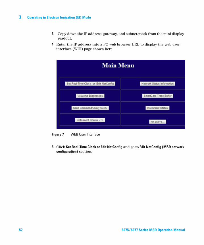
3 Copy down the IP address, gateway, and subnet mask from the mini display readout.
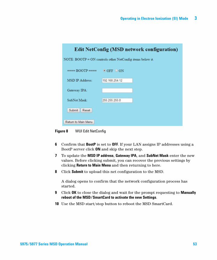
4 Enter the IP address into a PC web browser URL to display the web user interface (WUI) page shown here.
5 Click Set Real-Time Clock or Edit NetConfig and go to Edit NetConfig (MSD network configuration) section.
Figure 7 WEB User Interface
5975/5977 Series MSD Operation Manual
Operating in Electron Ionization (EI) Mode 3
5975/5977 Series M
6 Confirm that BootP is set to OFF. If your LAN assigns IP addresses using a BootP server click ON and skip the next step.
7 To update the MSD IP address, Gateway IPA, and SubNet Mask enter the new values. Before clicking submit, you can recover the previous settings by clicking Return to Main Menu and then returning to here.
8 Click Submit to upload this net configuration to the MSD. A dialog opens to confirm that the network configuration process has started.
9 Click OK to close the dialog and wait for the prompt requesting to Manually reboot of the MSD/SmartCard to activate the new Settings.
10 Use the MSD start/stop button to reboot the MSD SmartCard.
Figure 8 WUI Edit NetConfig
SD Operation Manual 53
3 Operating in Electron Ionization (EI) Mode
Operating the 5975/5977 MSD from the local control panel (LCP)
54
Agilent 5975 and 5977 MSD models introduced before the 5977B MSD have a local control panel (LCP). The LCP shows the status of the MSD or initiates a task on the MSD without using the data acquisition software.
Only certain features are available from the LCP. The data acquisition software is the full-featured controller for most instrument control operations.
Modes of operation
The LCP has two modes of operation: Status and Menu.Status mode requires no interaction and simply displays the current status of the MSD instrument or its various communication connections. If you select [Menu], then [No/Cancel], you will be returned to the Status mode.
Menu mode allows you to query various aspects of the GC/MSD and to initiate some actions like running a method or sequence or preparing to vent the system.
To access a particular menu option:
Use one or more of the following keys as appropriate to respond to prompts or select options:
Press [Menu] until the desired menu appears.
Press [Item] until the desired menu item appears.
Use [Up] to increase the displayed value or to scroll up (such as in a message list).
Use [Down] to decrease the displayed value or to scroll down (such as in a message
list).
5975/5977 Series MSD Operation Manual
Operating in Electron Ionization (EI) Mode 3
5975/5977 Series M
After you make your selection, or if you cycle through all available menus, the display automatically returns to Status mode.
Pressing [Menu], then [No/Cancel], will always display the Status mode.
Pressing [No/Cancel] twice will always return to the Status mode.
Use [Yes/Select] to accept the current value.
Use [No/Cancel] to return to the Status mode.
SD Operation Manual 55
3 Operating in Electron Ionization (EI) Mode
LCP Status Messages
56
The following messages may be displayed on the LCP to inform you of the status of the MSD system. If the LCP is currently in Menu mode, cycle through the menus to return to Status mode. No messages will be displayed if data acquisition software is not controlling the MSD.
ChemStation Loading <timestamp>
The Agilent OpenLAB CDS software is starting up.
Executing <type>tune
A tuning procedure is in progress (type = QuickTune or Autotune).
Instrument Available <timestamp>
The Agilent OpenLAB CDS software is not running.
Loading Method <method name>
Method parameters are being sent to the MSD.
Loading MSD Firmware
The MSD’s firmware is being initialized.
The following messages alternately appear on the LCP if the MSD does NOT complete its bootup sequence properly:
Server not Found Check LAN Connection
Seeking Server Bootp Query xxx
These messages indicate that the MSD has not received its unique IP address from the Windows Service. If the messages persist after you have logged onto your account in the Agilent OpenLAB CDS program, consult the Troubleshooting section of the Software Installation manual.
Loading OS
The operating system of the instrument controller is being initialized.
5975/5977 Series MSD Operation Manual
Operating in Electron Ionization (EI) Mode 3
5975/5977 Series M
<method> Complete <timestamp>
The run and subsequent data processing are done. The same message appears even if the run was terminated prematurely.
Method Loaded <method name>
Method parameters were sent to the MSD.
MS locked by <computer name>
MS parameters can only be changed from the Agilent OpenLAB CDS software.
Press Sideplate
A reminder during startup to press the MSD sideplate to ensure an adequate vacuum seal.
Run: <method> Acquiring <datafile>
A run is in progress; data is being acquired to the designated data file.
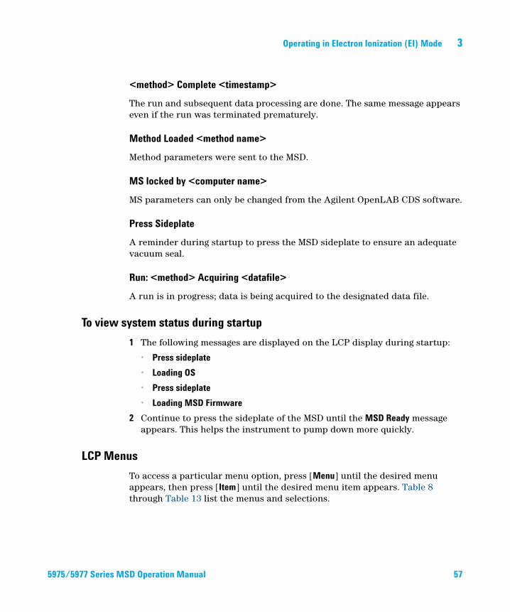
To view system status during startup
1 The following messages are displayed on the LCP display during startup:
• Press sideplate
• Loading OS
• Press sideplate
• Loading MSD Firmware
2 Continue to press the sideplate of the MSD until the MSD Ready message appears. This helps the instrument to pump down more quickly.
LCP Menus
To access a particular menu option, press [Menu] until the desired menu appears, then press [Item] until the desired menu item appears. Table 8 through Table 13 list the menus and selections.
SD Operation Manual 57
58
3 Operating in Electron Ionization (EI) Mode
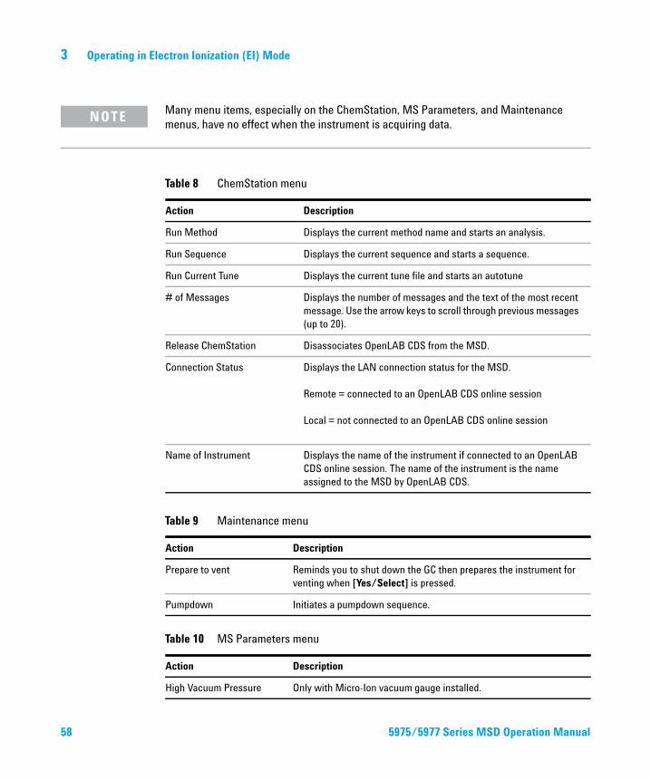
Many menu items, especially on the ChemStation, MS Parameters, and Maintenance
NOTEmenus, have no effect when the instrument is acquiring data.Table 8 ChemStation menu
Action Description
Run Method Displays the current method name and starts an analysis.
Run Sequence Displays the current sequence and starts a sequence.
Run Current Tune Displays the current tune file and starts an autotune
# of Messages Displays the number of messages and the text of the most recent
message. Use the arrow keys to scroll through previous messages
(up to 20).
Release ChemStation Disassociates OpenLAB CDS from the MSD.
Connection Status Displays the LAN connection status for the MSD.
Remote = connected to an OpenLAB CDS online session
Local = not connected to an OpenLAB CDS online session
Name of Instrument Displays the name of the instrument if connected to an OpenLAB
CDS online session. The name of the instrument is the name
assigned to the MSD by OpenLAB CDS.
Table 9 Maintenance menu
Action Description
Prepare to vent Reminds you to shut down the GC then prepares the instrument for
venting when [Yes/Select] is pressed.
Pumpdown Initiates a pumpdown sequence.
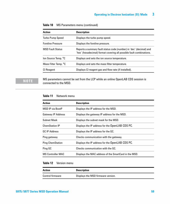
Table 10 MS Parameters menu
Action Description
High Vacuum Pressure Only with Micro-Ion vacuum gauge installed.
5975/5977 Series MSD Operation Manual
Operating in Electron Ionization (EI) Mode 3
5975/5977 Series M
Turbo Pump Speed Displays the turbo pump speed.
Foreline Pressure Displays the foreline pressure.
MSD Fault Status Reports a summary fault status code (number) in ‘dec’ (decimal) and
‘hex’ (hexadecimal) format covering all possible fault combinations.
Ion Source Temp, oC Displays and sets the ion source temperature.
Mass Filter Temp, oC Displays and sets the mass filter temperature.
CI Reagent Displays CI reagent gas and flow rate (if installed).
Table 10 MS Parameters menu (continued)
Action Description
MS parameters cannot be set from the LCP while an online OpenLAB CDS session is
NOTEconnected to the MSD.Table 11 Network menu
Action Description
MSD IP via BootP Displays the IP address for the MSD.
Gateway IP Address Displays the gateway IP address for the MSD.
Subnet Mask Displays the subnet mask for the MSD.
ChemStation IP Displays the IP address for the OpenLAB CDS PC.
GC IP Address Displays the IP address for the GC.
Ping gateway Checks communication with the gateway.
Ping ChemStation Displays the IP address for the OpenLAB CDS PC.
Ping GC Checks communication with the GC.
MS Controller MAC Displays the MAC address of the SmartCard in the MSD.
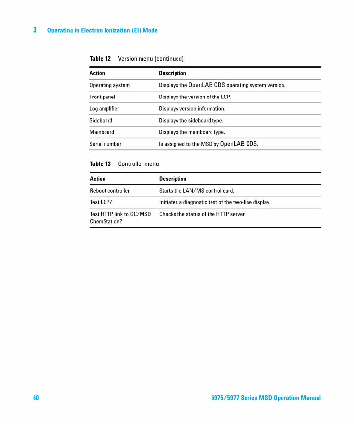
Table 12 Version menu
Action Description
Control firmware Displays the MSD firmware version.
SD Operation Manual 59
60
3 Operating in Electron Ionization (EI) Mode
Operating system Displays the OpenLAB CDS operating system version.
Front panel Displays the version of the LCP.
Log amplifier Displays version information.
Sideboard Displays the sideboard type.
Mainboard Displays the mainboard type.
Serial number Is assigned to the MSD by OpenLAB CDS.
Table 13 Controller menu
Action Description
Reboot controller Starts the LAN/MS control card.
Test LCP? Initiates a diagnostic test of the two-line display.
Test HTTP link to GC/MSD
ChemStation?
Checks the status of the HTTP server.
Table 12 Version menu (continued)
Action Description
5975/5977 Series MSD Operation Manual
Operating in Electron Ionization (EI) Mode 3
eModule mini display readout
5975/5977 Series M
This section only applies to the 5977B MSD. Earlier 5975/5977 MSD models do not have this feature.
The eModule mini display, accessible when the analyzer door cover is open, allows the operator to view the LAN configuration of the instrument including its IP address, subnet mask, default gateway, and MAC address. This LAN configuration can be changed using the GC control panel or the web user interface (WUI) from a web browser.
Front Panel Instrument Status LED
This section only applies to the 5977B MSD. Earlier 5975/5977 MSD models do not have this feature.
Through the front panel Instrument Status LED, the operator can view the current status of the instrument using color codes and LED on/off timing.
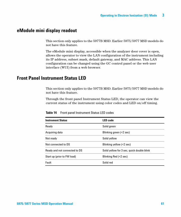
Table 14 Front panel Instrument Status LED codes
Instrument Status LED code
Ready Solid green
Acquiring data Blinking green (<2 sec)
Not ready Solid yellow
Not connected to DS Blinking yellow (<2 sec)
Ready and not connected to DS Solid yellow for 3 sec, quick double blink
Start up (prior to FW load) Blinking Red (<2 sec)
Fault Solid red
SD Operation Manual 61
3 Operating in Electron Ionization (EI) Mode
The GC/MSD Interface
62
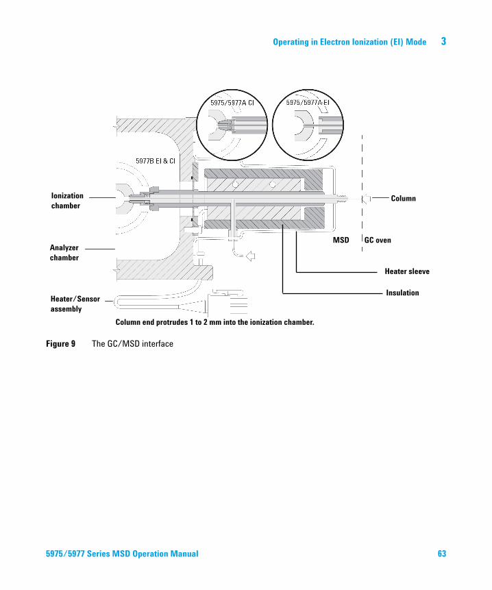
The GC/MSD interface (Figure 9 on page 63) is a heated conduit into the MSD for the capillary column. It is bolted onto the right side of the analyzer chamber, with an O-ring seal. It has a protective cover which should be left in place.
One end of the GC/MSD interface passes through the side of the gas chromatograph and extends into the GC oven. This end is threaded to allow connection of the column with a nut and ferrule. The other end of the interface fits into the ion source. The last 1 to 2 mm of the capillary column extend past the end of the guide tube and into the ionization chamber.
The GC/MSD interface is heated by an electric cartridge heater. Normally, the heater is powered and controlled by Thermal Aux #2 heated zone of the GC. The interface temperature can be set from OpenLAB or from the gas chromatograph. A sensor (thermocouple) in the interface monitors the temperature.
The GC/MSD interface should be operated in the 250 to 350 C range. Subject to that restriction, the interface temperature should be slightly higher than the maximum GC oven temperature, but never higher than the maximum column temperature.
The extractor ion source requires a tip seal (G3870-20542). The standard EI sources constructed of stainless steel or inert material do not need a tip seal.
See also
“To Install a Capillary Column in the GC/MS Interface Using the Self-Tightening Column Nut”on page 37.
WARNING The GC/MSD interface operates at high temperatures. If you touch it when it is hot, it will burn you.
5975/5977 Series MSD Operation Manual
Operating in Electron Ionization (EI) Mode 3
Figure 9 The GC/MSD interface
Ionization chamber
Analyzer chamber
Heater/Sensor assembly
MSD GC oven
Heater sleeve
Insulation
Column
Column end protrudes 1 to 2 mm into the ionization chamber.
5975/5977 Series MSD Operation Manual
63
3 Operating in Electron Ionization (EI) Mode
Before You Turn On the MSD
64
Verify the following before you turn on or attempt to operate the MSD.
• The vent valve must be closed (the knob turned all the way clockwise).
• All other vacuum seals and fittings must be in place and fastened correctly. The front side plate screw should not be tightened, unless hazardous carrier or reagent gases are being used.
• The MSD is connected to a grounded power source.
• The GC/MSD interface extends into the GC oven.
• A conditioned capillary column is installed in the GC inlet and in the GC/MSD interface.
• The GC is on, but the heated zones for the GC/MSD interface, the GC inlet, and the oven are off.
• Carrier gas of at least 99.9995% purity is plumbed to the GC with the recommended traps.
• If hydrogen is used as carrier gas, carrier gas flow must be off and the front sideplate thumbscrew must be loosely fastened.
• The foreline pump exhaust is properly vented.
WARNING The exhaust from the foreline pump contains solvents and the chemicals you are analyzing. If using the standard foreline pump, it also contains traces of pump oil. If you are using toxic solvents or analyzing toxic chemicals, remove the oil trap/mist filter (standard pump) and install a hose (11-mm id) to take the foreline pump exhaust outside or to a fume (exhaust) hood. Be sure to comply with local regulations. The oil trap supplied with the standard pump stops only pump oil. It does not trap or filter out toxic chemicals.
If you are using hydrogen as a carrier gas, do not start carrier gas flow until the
WARNINGMSD has been pumped down. If the vacuum pumps are off, hydrogen will accumulate in the MSD and an explosion may occur. Read “Hydrogen Safety”on page 18 before operating the MSD with hydrogen carrier gas.5975/5977 Series MSD Operation Manual
Operating in Electron Ionization (EI) Mode 3
Pumping Down
5975/5977 Series M
The data system helps you pump down the MSD. The process is mostly automated. Once you close the vent valve and turn on the main power switch (while pressing on the sideplate), the MSD pumps down by itself. The data system software monitors and displays system status during pumpdown. When the pressure is low enough, the program turns on the ion source and mass filter heaters and prompts you to turn on the GC/MSD interface heater. The MSD will shut down if it cannot pump down correctly.
From the Instrument Status Dashboard, OpenLAB CDS can display:
• Motor speed for turbo pump MSDs (percent spin speed)
• Foreline pressure for diffusion pump MSDs
• Analyzer chamber pressure (vacuum) for MSDs equipped with the optional Micro-Ion Gauge Controller (G3397A for the 5975 and G3397B for the 5977).
Controlling Temperatures
MSD temperatures are controlled through the data system. The MSD has independent heaters and temperature sensors for the ion source and quadrupole mass filter. You can adjust the setpoints and view these temperatures from the data system or from the local control panel.
Normally, the GC/MSD interface heater is powered and controlled by the Thermal Aux #2 heated zone of the GC. The GC/MSD interface temperature can be set and monitored from the data system or from the 7890B GC control panel.
Controlling Column Flow
Carrier gas flow is controlled by inlet pressure in the GC. For a given inlet pressure, column flow will decrease as the GC oven temperature increases. With electronic pneumatic control (EPC) and the column mode set to Constant Flow, the same column flow is maintained regardless of temperature.
SD Operation Manual 65
66
3 Operating in Electron Ionization (EI) Mode
The MSD can be used to measure actual column flow. You inject a small amount of air or other unretained chemical and time how long it takes to reach the MSD. With this time measurement, you can calculate the column flow. See “To Calibrate Column Flow Linear Velocity”on page 72.
Venting the MSD
A program in the data system guides you through the venting process. It turns off the GC and MSD heaters and diffusion pump heater or the turbo pump at the correct time. It also lets you monitor temperatures in the MSD and indicates when to vent the MSD.
The MSD will be damaged by incorrect venting. A diffusion pump will backstream vaporized pump fluid onto the analyzer if the MSD is vented before the diffusion pump has fully cooled. A turbo pump will be damaged if it is vented while spinning at more than 50% of its normal operating speed.
WARNING Make sure the GC/MSD interface and the analyzer zones are cool (below 100 °C) before you vent the MSD. A temperature of 100 °C is hot enough to burn skin; always wear cloth gloves when handling analyzer parts.
WARNING If you are using hydrogen as a carrier gas, the carrier gas flow must be off before turning off the MSD power. If the foreline pump is off, hydrogen will accumulate in the MSD and an explosion may occur. Read “Hydrogen Safety”on page 18 before operating the MSD with hydrogen carrier gas.
CAUTION Never vent the MSD by allowing air in through either end of the foreline hose. Use the
vent valve or remove the column nut and column.
Do not vent while the turbo pump is still spinning at more than 50%.
Do not exceed the maximum recommended total gas flow. See “5977B Series MSD
features”on page 14.
5975/5977 Series MSD Operation Manual
Operating in Electron Ionization (EI) Mode 3
Set MS Analyzer Temperatures
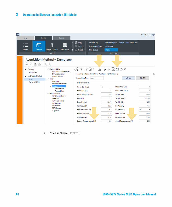
5975/5977 Series M
Setpoints for the MSD ion source and mass filter (quad) temperatures are stored in the current tune (*.u) file. When a method is loaded, the setpoints in the tune file associated with that method are downloaded automatically.
1 Enable Tune Control and click Manual Tune > Parameters.
2 Enter the Source temp (°C) and Quad temp (°C) (mass filter).
The GC/MSD interface, ion source, and quadrupole heated zones interact. The analyzer heaters may not be able to accurately control temperatures if the setpoint for one zone is much different from that of an adjacent zone.
Do not exceed 200 °C for the quadrupole or 350 °C for the source.
CAUTION3 Click Download tune file to download these temperature setpoints to the MS and change the current control temperatures to these values.
4 Click Save the tune parameters to make these temperature settings part of this tune file or click Save tune file as to create a new tune file with these values.
5 Run an autotune if you want these new temperatures in an autotune file.
SD Operation Manual 67
68
3 Operating in Electron Ionization (EI) Mode
6 Release Tune Control.
5975/5977 Series MSD Operation Manual
Operating in Electron Ionization (EI) Mode 3
Enable the GC/MS Interface and Oven
5975/5977 Series M
Procedure
1 Click Method > Instrument Setup > GC > Aux Heaters.2 Select On for Thermal Aux 2.3 Click Oven and select On.4 Click Download Method to enable these temperature zones in the GC.
5 Save the method.
SD Operation Manual 69
3 Operating in Electron Ionization (EI) Mode
View MSD Temperatures and Vacuum
70
Pressure monitoring requires an optional Micro-Ion vacuum gauge (G3397A for the 5975 and G3397B for the 5977)..
WARNING If you are using hydrogen as a carrier gas, do not turn on the Micro-Ion vacuum gauge if there is any possibility that hydrogen has accumulated in the analyzer chamber. Read “Hydrogen Safety”on page 18 before operating the MSD with hydrogen carrier gas.
Select Instrument Status in the windows area and click MSD to display the MSD’s actuals values including the source and quad temperatures and quad manifold vacuum pressure.
5975/5977 Series MSD Operation Manual
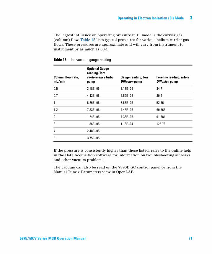
Operating in Electron Ionization (EI) Mode 3
5975/5977 Series M
The largest influence on operating pressure in EI mode is the carrier gas (column) flow. Table 15 lists typical pressures for various helium carrier gas flows. These pressures are approximate and will vary from instrument to instrument by as much as 30%.
If the pressure is consistently higher than those listed, refer to the online help in the Data Acquisition software for information on troubleshooting air leaks and other vacuum problems.
The vacuum can also be read on the 7890B GC control panel or from the Manual Tune > Parameters view in OpenLAB.
Table 15 Ion vacuum gauge reading
Column flow rate, mL/min
Optional Gauge reading, Torr Performance turbo pump
Gauge reading, Torr Diffusion pump
Foreline reading, mTorr Diffusion pump
0.5 3.18E–06 2.18E–05 34.7
0.7 4.42E–06 2.59E–05 39.4
1 6.26E–06 3.66E–05 52.86
1.2 7.33E–06 4.46E–05 60.866
2 1.24E–05 7.33E–05 91.784
3 1.86E–05 1.13E–04 125.76
4 2.48E–05
6 3.75E–05
SD Operation Manual 71
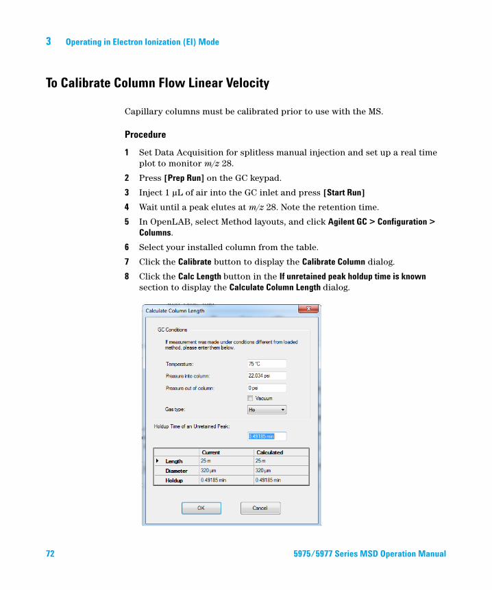
3 Operating in Electron Ionization (EI) Mode
To Calibrate Column Flow Linear Velocity
72
Capillary columns must be calibrated prior to use with the MS.
Procedure
1 Set Data Acquisition for splitless manual injection and set up a real time plot to monitor m/z 28.
2 Press [Prep Run] on the GC keypad.
3 Inject 1 µL of air into the GC inlet and press [Start Run]
4 Wait until a peak elutes at m/z 28. Note the retention time.
5 In OpenLAB, select Method layouts, and click Agilent GC > Configuration > Columns.
6 Select your installed column from the table.
7 Click the Calibrate button to display the Calibrate Column dialog.
8 Click the Calc Length button in the If unretained peak holdup time is known section to display the Calculate Column Length dialog.
5975/5977 Series MSD Operation Manual
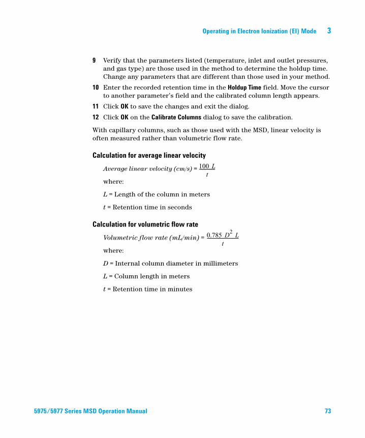
Operating in Electron Ionization (EI) Mode 3
5975/5977 Series M
9 Verify that the parameters listed (temperature, inlet and outlet pressures, and gas type) are those used in the method to determine the holdup time. Change any parameters that are different than those used in your method.
10 Enter the recorded retention time in the Holdup Time field. Move the cursor to another parameter’s field and the calibrated column length appears.
11 Click OK to save the changes and exit the dialog.
12 Click OK on the Calibrate Columns dialog to save the calibration.
With capillary columns, such as those used with the MSD, linear velocity is often measured rather than volumetric flow rate.
Calculation for average linear velocity
Average linear velocity (cm/s) =
where:
L = Length of the column in meters
t = Retention time in seconds
Calculation for volumetric flow rate
Volumetric flow rate (mL/min) =
where:
D = Internal column diameter in millimeters
L = Column length in meters
t = Retention time in minutes
100 Lt
--------------
0.785 D2 Lt
----------------------------
SD Operation Manual 73
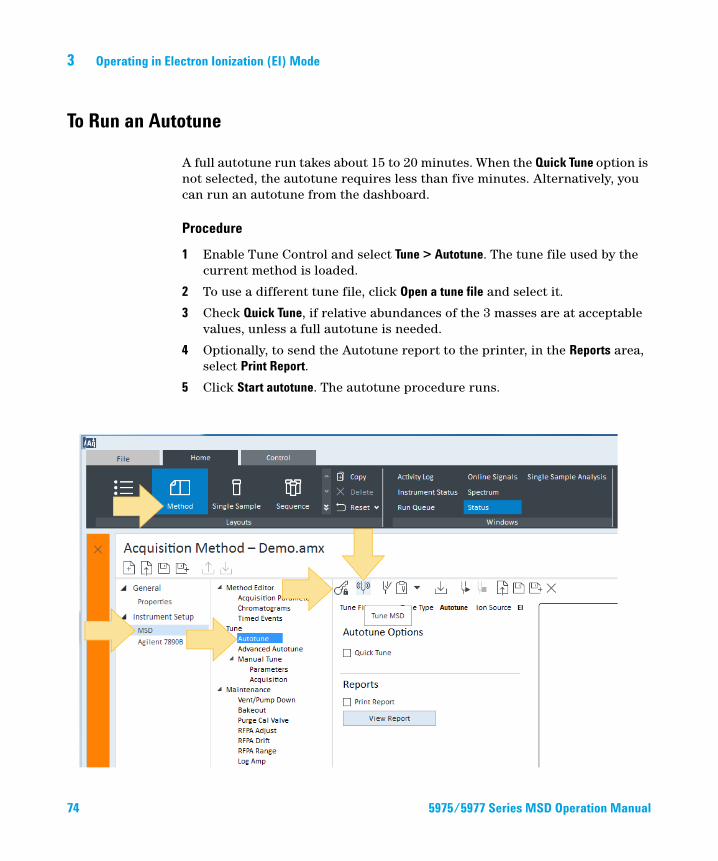
3 Operating in Electron Ionization (EI) Mode
To Run an Autotune
74
A full autotune run takes about 15 to 20 minutes. When the Quick Tune option is not selected, the autotune requires less than five minutes. Alternatively, you can run an autotune from the dashboard.
Procedure
1 Enable Tune Control and select Tune > Autotune. The tune file used by the current method is loaded.
2 To use a different tune file, click Open a tune file and select it.
3 Check Quick Tune, if relative abundances of the 3 masses are at acceptable values, unless a full autotune is needed.
4 Optionally, to send the Autotune report to the printer, in the Reports area, select Print Report.
5 Click Start autotune. The autotune procedure runs.
5975/5977 Series MSD Operation Manual
Operating in Electron Ionization (EI) Mode 3
5975/5977 Series M
6 Release Tune Control.
7 As needed, generate an Evaluate Tune Report.
SD Operation Manual 75
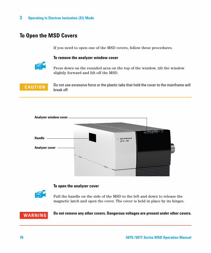
3 Operating in Electron Ionization (EI) Mode
To Open the MSD Covers
76
If you need to open one of the MSD covers, follow these procedures.
To remove the analyzer window cover
Press down on the rounded area on the top of the window, tilt the window slightly forward and lift off the MSD.
CAUTION Do not use excessive force or the plastic tabs that hold the cover to the mainframe will
break off.
Analyzer window cover
Handle
Analyzer cover
To open the analyzer cover
Pull the handle on the side of the MSD to the left and down to release the magnetic latch and open the cover. The cover is held in place by its hinges.
Do not remove any other covers. Dangerous voltages are present under other covers.
WARNING5975/5977 Series MSD Operation Manual
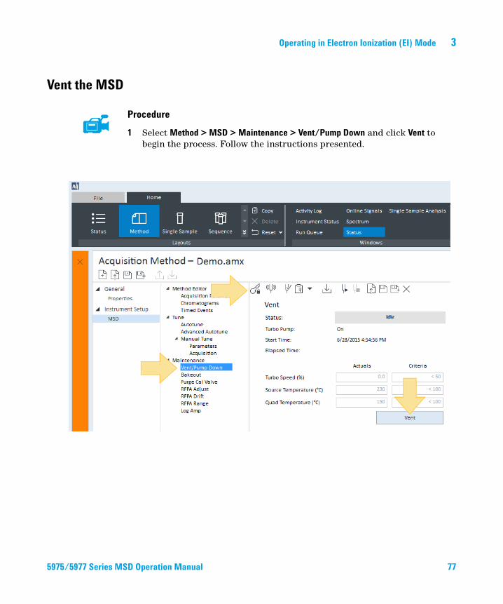
Operating in Electron Ionization (EI) Mode 3
Vent the MSD
5975/5977 Series M
Procedure
1 Select Method > MSD > Maintenance > Vent/Pump Down and click Vent to begin the process. Follow the instructions presented.
SD Operation Manual 77
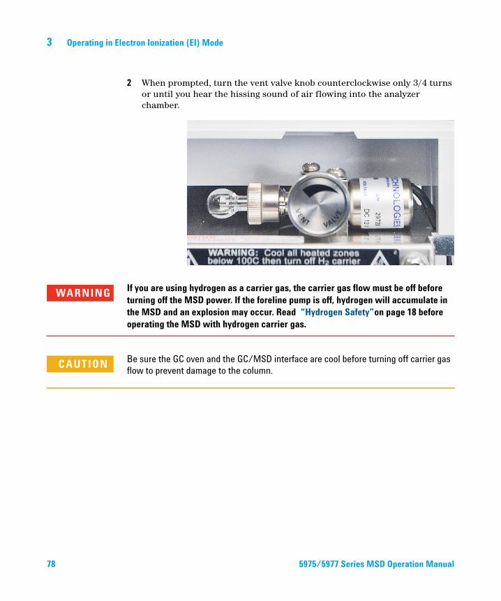
78
3 Operating in Electron Ionization (EI) Mode
2 When prompted, turn the vent valve knob counterclockwise only 3/4 turns or until you hear the hissing sound of air flowing into the analyzer chamber.
WARNING If you are using hydrogen as a carrier gas, the carrier gas flow must be off before turning off the MSD power. If the foreline pump is off, hydrogen will accumulate in the MSD and an explosion may occur. Read “Hydrogen Safety”on page 18 before operating the MSD with hydrogen carrier gas.
CAUTION Be sure the GC oven and the GC/MSD interface are cool before turning off carrier gas
flow to prevent damage to the column.
5975/5977 Series MSD Operation Manual
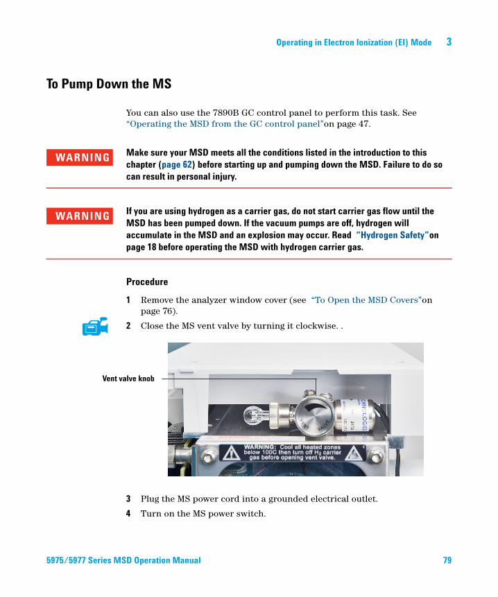
Operating in Electron Ionization (EI) Mode 3
To Pump Down the MS
5975/5977 Series M
You can also use the 7890B GC control panel to perform this task. See “Operating the MSD from the GC control panel”on page 47.
WARNING Make sure your MSD meets all the conditions listed in the introduction to this chapter (page 62) before starting up and pumping down the MSD. Failure to do so can result in personal injury.
WARNING If you are using hydrogen as a carrier gas, do not start carrier gas flow until the MSD has been pumped down. If the vacuum pumps are off, hydrogen will accumulate in the MSD and an explosion may occur. Read “Hydrogen Safety”on page 18 before operating the MSD with hydrogen carrier gas.
Procedure
1 Remove the analyzer window cover (see “To Open the MSD Covers”on page 76).
2 Close the MS vent valve by turning it clockwise. .
Vent valve knob
3 Plug the MS power cord into a grounded electrical outlet.
4 Turn on the MS power switch.
SD Operation Manual 79

80
3 Operating in Electron Ionization (EI) Mode
5 Press lightly on the metal box of the analyzer quad driver board to ensure a correct seal.
6 Start the OpenLAB Data Acquisition program. If the MS was configured for multiple ion source types, you are prompted for the ion source type that is currently installed. Click on the installed source type if prompted.
7 If the selected ion source in the previous step does not match the source used in the current method's tune file, you are prompted to enter a method with the correct ion source type. Load the correct method for an EI, PCI, or NCI source type.
8 Enable Tune Control and click Maintenance.
9 Click Pump Down to start this procedure.
Do not turn on any GC heated zones until carrier gas flow is on. Heating a column with
CAUTIONno carrier gas flow will damage the column.5975/5977 Series MSD Operation Manual
Operating in Electron Ionization (EI) Mode 3
5975/5977 Series M
10 You are prompted to turn on the transfer line heater and the GC oven. Click OK when you have done so.
11 The software will turn on the ion source and mass filter (quad) heaters. The temperature setpoints are stored in the current autotune file. The pump down status and "the MSD actual parameters" in comparison to "criteria required for pump down completion" is shown.
12 Wait for the MS to reach thermal equilibrium. After the message Okay to run appears, wait 2 hours for the MS to reach thermal equilibrium. Data acquired before the MS has reached thermal equilibrium may not be reproducible.
13 When the pumpdown is finished, click OK to clear the pump down status window.
14 Tune the MS.
SD Operation Manual 81
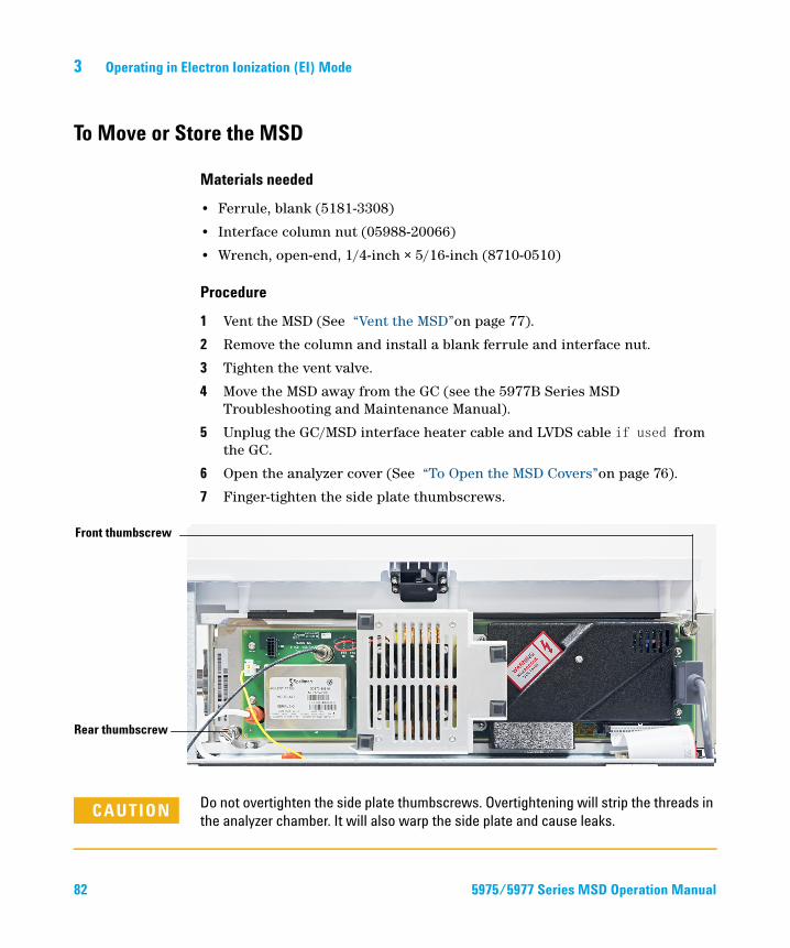
3 Operating in Electron Ionization (EI) Mode
To Move or Store the MSD
82
Materials needed
• Ferrule, blank (5181-3308)
• Interface column nut (05988-20066)
• Wrench, open-end, 1/4-inch × 5/16-inch (8710-0510)
Procedure
1 Vent the MSD (See “Vent the MSD”on page 77).
2 Remove the column and install a blank ferrule and interface nut.
3 Tighten the vent valve.
4 Move the MSD away from the GC (see the 5977B Series MSD Troubleshooting and Maintenance Manual).
5 Unplug the GC/MSD interface heater cable and LVDS cable from the GC.
6 Open the analyzer cover (See “To Open the MSD Covers”on page 76).
7 Finger-tighten the side plate thumbscrews.
CAUTION Do not overtighten the side plate thumbscrews. Overtightening will strip the threads in
the analyzer chamber. It will also warp the side plate and cause leaks.
Front thumbscrew
Rear thumbscrew
5975/5977 Series MSD Operation Manual
Operating in Electron Ionization (EI) Mode 3
5975/5977 Series M
8 Plug the MSD power cord in.
9 Switch the MSD on to establish a rough vacuum. Verify that the turbo pump speed is greater than 50%, or that the foreline pressure is 1 Torr.
10 Switch the MSD off.
11 Close the analyzer cover.
12 Disconnect the LAN, remote, and power cables.
The MSD can now be stored or moved. The foreline pump cannot be disconnected; it must be moved with the MSD. Make sure the MSD remains upright and is never tipped on its side or inverted.
CAUTION The MSD must remain upright at all times. If you need to ship your MSD to another
location, contact your Agilent Technologies service representative for advice about
packing and shipping.
SD Operation Manual 83

3 Operating in Electron Ionization (EI) Mode
84 5975/5977 Series MSD Operation Manual
Agilent 5977B Series Agilent 5975/5977 MSD for OpenLAB CDSOperation Manual
4General Maintenance
Before Starting 86
Maintaining the Vacuum System 91
Maintaining the Analyzer 92
To Open the Analyzer Chamber 94
To Remove the EI Ion Source 96
To Disassemble the Standard or Inert EI Ion Source 99
To Disassemble the Extractor EI Ion Source 102
To Clean the EI Ion Source 105
To Assemble a Standard or Inert EI Ion Source 110
To Assemble the Extractor EI Ion Source 113
To Replace a Filament in an EI Ion Source 116
To Install the EI Ion Source 118
To Attach Wiring from the Ion Source to the feedthrough board 119
To Replace the Electron Multiplier Horn 122
To Close the Analyzer Chamber 125
85Agilent Technologies
4 General Maintenance
Before Starting
86
You can perform much of the maintenance required by your MSD. For your safety, read all of the information in this introduction before performing any maintenance tasks.
nce schedule
Scheduled maintenance
Table 16 Maintena
Task Every week Every 6 months Every year As needed
Tune the MSD X
Check the foreline pump oil level X
Check the calibration vial(s) X
Replace the foreline pump oil X
Replace the diffusion pump fluid X
Check the dry foreline pump X
Change the dry foreline pump tip seal X
Change the foreline pump exhaust filter X
Clean the ion source X
Check the carrier gas trap(s) on the GC and MSD X
Replace the worn out parts X
Lubricate sideplate or vent valve O-rings* X
Replace GC gas supplies X
* Vacuum seals other than the side plate O-ring and vent valve O-ring do not need to be lubricated. Lubricating other seals can interfere with their correct function.
Common maintenance tasks are listed in Table 16. Performing these tasks when scheduled can reduce operating problems, prolong system life, and reduce overall operating costs.
5975/5977 Series MSD Operation Manual
General Maintenance 4
5975/5977 Series M
Keep a record of system performance (tune reports) and maintenance operations performed. This makes it easier to identify variations from normal operation and to take corrective action.
Tools, spare parts, and supplies
Some of the required tools, spare parts, and supplies are included in the GC shipping kit, MSD shipping kit, or MSD tool kit. You must supply others yourself. Each maintenance procedure includes a list of the materials required for that procedure.
High voltage precautions
Whenever the MSD is plugged in, even if the power switch is off, potentially dangerous voltage (120 VAC or 200/240 VAC) exists on:
• The wiring and fuses between where the power cord enters the instrument and the power switch
When the power switch is on, potentially dangerous voltages exist on:
• Electronic circuit boards
• Toroidal transformer
• Wires and cables between these boards
• Wires and cables between these boards and the connectors on the back panel of the MSD
• Some connectors on the back panel (for example, the foreline power receptacle)
Normally, all of these parts are shielded by safety covers. As long as the safety covers are in place, it should be difficult to accidentally make contact with dangerous voltages.
WARNING Perform no maintenance with the MSD turned on or plugged into its power source unless you are instructed to by one of the procedures in this chapter.
SD Operation Manual 87
88
4 General Maintenance
Some procedures in this chapter require access to the inside of the MSD while the power switch is on. Do not remove any of the electronics safety covers in any of these procedures. To reduce the risk of electric shock, follow the procedures carefully.
Dangerous temperatures
Many parts in the MSD operate at, or reach, temperatures high enough to cause serious burns. These parts include, but are not limited to:
• GC inlet
• GC oven and its contents
• GC detector
• GC valve box
• Foreline pump
• Heated MSD ion source, interface, and quadrupole
WARNING Never touch these parts while your MSD is on. After the MSD is turned off, give these parts enough time to cool before handling them.
WARNING The GC/MSD interface heater is powered by a thermal zone on the GC. The interface heater can be on, and at a dangerously high temperature, even though the MSD is off. The GC/MSD interface is well insulated. Even after it is turned off, it cools very slowly.
The foreline pump can cause burns if touched when operating. It has a safety shield
WARNINGto prevent the user from touching it.The GC inlets and GC oven also operate at very high temperatures. Use the same caution around these parts. See the documentation supplied with your GC for more information.
5975/5977 Series MSD Operation Manual
General Maintenance 4
Chemical residue
5975/5977 Series M
Only a small portion of your sample is ionized by the ion source. The majority of any sample passes through the ion source without being ionized. It is pumped away by the vacuum system. As a result, the exhaust from the foreline pump will contain traces of the carrier gas and your samples. Exhaust from the standard foreline pump also contains tiny droplets of foreline pump oil.
An oil trap is supplied with the standard foreline pump. This trap stops only pump oil droplets. It does not trap any other chemicals. If you are using toxic solvents or analyzing toxic chemicals, do not use this oil trap. For all foreline pumps, install a hose to take the exhaust from the foreline pump outdoors or into a fume hood vented to the outdoors. For the standard foreline pump, this requires removing the oil trap. Be sure to comply with your local air quality regulations.
WARNING The oil trap supplied with the standard foreline pump stops only foreline pump oil. It does not trap or filter out toxic chemicals. If you are using toxic solvents or analyzing toxic chemicals, remove the oil trap. Do not use the trap if you have a CI MSD. Install a hose to take the foreline pump exhaust outside or to a fume hood.
The fluids in the diffusion pump and standard foreline pump also collect traces of the samples being analyzed. All used pump fluid should be considered hazardous and handled accordingly. Dispose of used fluid correctly, as specified by your local regulations.
When replacing pump fluid, use appropriate chemical-resistant gloves and safety
WARNINGglasses. Avoid all contact with the fluid.Always perform any maintenance procedures using hazardous solvents under a
WARNINGfume hood. Be sure to operate the MS in a well-ventilated room.SD Operation Manual 89
4 General Maintenance
Electrostatic discharge
90
All of the printed circuit boards in the MSD contain components that can be damaged by electrostatic discharge (ESD). Do not handle or touch these boards unless absolutely necessary. In addition, wires, contacts, and cables can conduct ESD to the electronics boards to which they are connected. This is especially true of the mass filter (quadrupole) contact wires which can carry ESD to sensitive components on the side board. ESD damage may not cause immediate failure, but it will gradually degrade the performance and stability of your MSD.
When you work on or near printed circuit boards or when you work on components with wires, contacts, or cables connected to printed circuit boards, always use a grounded antistatic wrist strap and take other antistatic precautions. The wrist strap should be connected to a known good earth ground. If that is not possible, it should be connected to a conductive (metal) part of the assembly being worked on, but not to electronic components, exposed wires or traces, or pins on connectors.
Take extra precautions, such as a grounded antistatic mat, if you must work on components or assemblies that have been removed from the MSD. This includes the analyzer.
CAUTION To be effective, an antistatic wrist strap must fit snugly (not tight). A loose strap
provides little or no protection.
Antistatic precautions are not 100% effective. Handle electronic circuit boards as little
as possible and then only by the edges. Never touch components, exposed traces, or
pins on connectors and cables.
5975/5977 Series MSD Operation Manual
General Maintenance 4
Maintaining the Vacuum System
Periodic maintenance
5975/5977 Series M
As listed earlier in Table 16 on page 86, some maintenance tasks for the vacuum system must be performed periodically. These include:
• Checking the foreline pump fluid (every week)
• Checking the calibration vial(s) (every 6 months)
• Replacing the foreline pump oil (every 6 months)
• Tightening the foreline pump oil box screws (first oil change after installation)
• Replacing the diffusion pump fluid (once a year)
• Replacing the dry foreline pump seals (once a year)
Failure to perform these tasks as scheduled can result in decreased instrument performance. It can also result in damage to your instrument.
Other procedures
Tasks such as replacing a foreline vacuum gauge or Micro-Ion vacuum gauge should be performed only when needed. See the 5977B Series MSD Troubleshooting and Maintenance manual and see the online help in OpenLAB CDS GCMS Acquisition software for symptoms that indicate this type of maintenance is required. See the 5977B Series MSD Troubleshooting and Maintenance manual and see the online help in MassHunter GCMS Acquisition software for symptoms that indicate this type of maintenance is required.
More information is available
If you need more information about the locations or functions of vacuum system components, see the MSD Troubleshooting and Maintenance manual that was shipped with your instrument.
SD Operation Manual 91
4 General Maintenance
Maintaining the Analyzer
Scheduling
92
None of the analyzer components require periodic maintenance. Some tasks, however, must be performed when MSD behavior indicates they are necessary. These tasks include:
• Cleaning the ion source
• Replacing filaments
• Replacing the electron multiplier horn
The Agilent 5977B Series MSD Troubleshooting and Maintenance Manual provides information about symptoms that indicate the need for analyzer maintenance. The troubleshooting material in the online help in the OpenLAB CDS software provides more extensive information.
Precautions
Cleanliness
Keep components clean during analyzer maintenance. Analyzer maintenance involves opening the analyzer chamber and removing parts from the analyzer. During analyzer maintenance procedures, take care to avoid contaminating the analyzer or interior of the analyzer chamber. Wear clean gloves during all analyzer maintenance procedures. After cleaning, parts must be thoroughly baked out before they are reinstalled. After cleaning, analyzer parts should be placed only on clean, lint-free cloths.
CAUTION If not done correctly, analyzer maintenance can introduce contaminants into the MSD.
WARNING The analyzer operates at high temperatures. Do not touch any part until you are sure it is cool.
5975/5977 Series MSD Operation Manual
General Maintenance 4
5975/5977 Series M
Some parts can be damaged by electrostatic discharge
The wires, contacts, and cables connected to the analyzer components can carry electrostatic discharges (ESD) to the electronics boards to which they are connected. This is especially true of the mass filter (quadrupole) contact wires which can conduct ESD to sensitive components on the side board. ESD damage may not cause immediate failure but will gradually degrade performance and stability. See page 90 for more information.
CAUTION Electrostatic discharges to analyzer components are conducted to the side board
where they can damage sensitive components. Wear a grounded antistatic wrist strap
(see page 90) and take other antistatic precautions before you open the analyzer
chamber.
Some analyzer parts should not be disturbed
The mass filter (quadrupole) requires no periodic maintenance. In general, the mass filter should never be disturbed. In the event of extreme contamination, it can be cleaned, but such cleaning should only be done by a trained Agilent Technologies service representative. The HED ceramic insulator must never be touched.
More information is available
CAUTION Incorrect handling or cleaning of the mass filter can damage it and have a serious,
negative effect on instrument performance. Do not touch the HED ceramic insulator.
If you need more information about the locations or functions of analyzer components, refer to the Agilent 5977B Series MSD Troubleshooting and Maintenance Manual.
Many procedures in this chapter are illustrated with video clips.
SD Operation Manual 93
4 General Maintenance
To Open the Analyzer Chamber
94
The analyzer chamber should only be opened to clean or replace the ion source, change the detector’s EM, or to change a filament.
Materials needed
• Gloves, clean, lint-free
• Large (8650-0030)
• Small (8650-0029)
• Wrist strap, antistatic
• Small (9300-0969)
• Medium (9300-1257)
• Large (9300-0970)
Electrostatic discharges to analyzer components are conducted to the quad driver
CAUTIONboard, where they can damage sensitive components. Wear a grounded antistaticwrist strap and take other antistatic precautions (see “Electrostatic discharge” on
page 90) before you open the analyzer chamber.
Procedure
1 Vent the MS. (See “Pumping Down” on page 65.)
2 Open the left side panel. (See “To Open the Analyzer Chamber” on page 94.)
The analyzer, GC/MS interface, and other components in the analyzer chamber
WARNINGoperate at very high temperatures. Do not touch any part until you are sure it is cool.Always wear clean gloves to prevent contamination when working in the analyzer
CAUTIONchamber.3 Loosen the front analyzer side plate thumbscrews (Figure 10) if they are fastened.
5975/5977 Series MSD Operation Manual

General Maintenance 4
5975/5977 Series M
The bottom thumbscrew on the front analyzer side plate should be unfastened during normal use. It is only fastened during shipping. The top thumbscrew on the front side plate should only be fastened if hydrogen or other flammable or toxic substances are used for carrier gas.
CAUTION In the next step, if you feel resistance, stop. Do not try to force the side plate open.
Verify that the MS is vented. Verify that both the front and rear side plate screws are
completely loose.
4 Gently swing the side plate out.
Figure 10 The analyzer chamber
Feedthrough board
Ion source
Side plate
Analyzer
SD Operation Manual 95
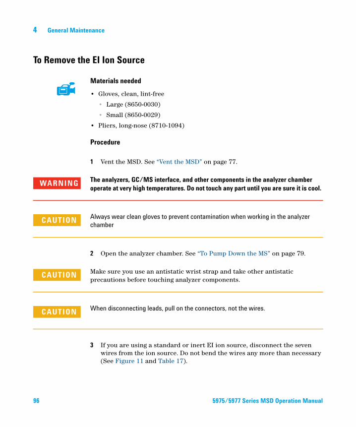
4 General Maintenance
To Remove the EI Ion Source
96
Materials needed
• Gloves, clean, lint-free
• Large (8650-0030)
• Small (8650-0029)
• Pliers, long-nose (8710-1094)
Procedure
1 Vent the MSD. See “Vent the MSD” on page 77.
The analyzers, GC/MS interface, and other components in the analyzer chamber
WARNINGoperate at very high temperatures. Do not touch any part until you are sure it is cool.CAUTION Always wear clean gloves to prevent contamination when working in the analyzer
chamber
2 Open the analyzer chamber. See “To Pump Down the MS” on page 79.
Make sure you use an antistatic wrist strap and take other antistatic
CAUTIONprecautions before touching analyzer components.CAUTION When disconnecting leads, pull on the connectors, not the wires.
3 If you are using a standard or inert EI ion source, disconnect the seven wires from the ion source. Do not bend the wires any more than necessary (See Figure 11 and Table 17).
5975/5977 Series MSD Operation Manual
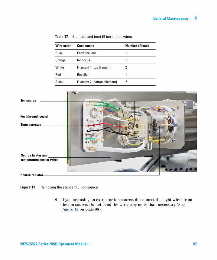
General Maintenance 4
5975/5977 Series M
Table 17 Standard and inert EI ion source wires
Wire color Connects to Number of leads
Blue Entrance lens 1
Orange Ion focus 1
White Filament 1 (top filament) 2
Red Repeller 1
Black Filament 2 (bottom filament) 2
Figure 11 Removing the standard EI ion source
Feedthrough board
Ion source
Thumbscrews
Source heater and temperature sensor wires
Source radiator
4 If you are using an extractor ion source, disconnect the eight wires from the ion source. Do not bend the wires any more than necessary (See Figure 12 on page 98).
SD Operation Manual 97
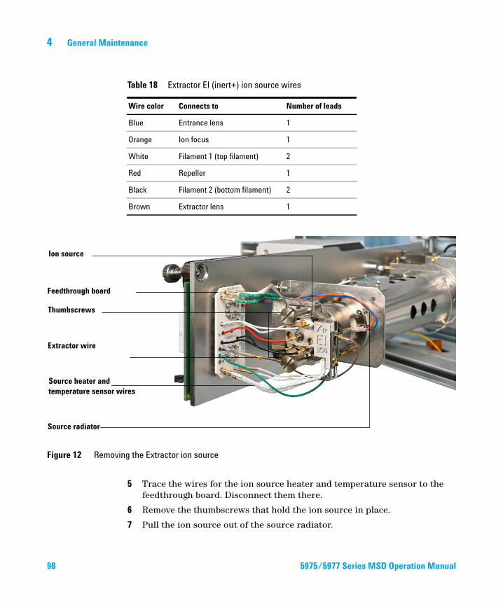
98
4 General Maintenance
Table 18 Extractor EI (inert+) ion source wires
Wire color Connects to Number of leads
Blue Entrance lens 1
Orange Ion focus 1
White Filament 1 (top filament) 2
Red Repeller 1
Black Filament 2 (bottom filament) 2
Brown Extractor lens 1
Figure 12 Removing the Extractor ion source
Feedthrough board
Ion source
Thumbscrews
Source heater and temperature sensor wires
Source radiator
Extractor wire
5 Trace the wires for the ion source heater and temperature sensor to the feedthrough board. Disconnect them there.
6 Remove the thumbscrews that hold the ion source in place.
7 Pull the ion source out of the source radiator.
5975/5977 Series MSD Operation Manual
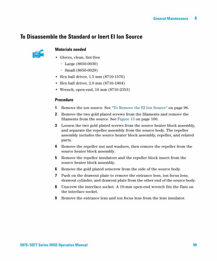
General Maintenance 4
To Disassemble the Standard or Inert EI Ion Source
5975/5977 Series M
Materials needed
• Gloves, clean, lint-free
• Large (8650-0030)
• Small (8650-0029)
• Hex ball driver, 1.5 mm (8710-1570)
• Hex ball driver, 2.0 mm (8710-1804)
• Wrench, open-end, 10 mm (8710-2353)
Procedure
1 Remove the ion source. See “To Remove the EI Ion Source” on page 96.
2 Remove the two gold plated screws from the filaments and remove the filaments from the source. See Figure 13 on page 100.
3 Loosen the two gold plated screws from the source heater block assembly, and separate the repeller assembly from the source body. The repeller assembly includes the source heater block assembly, repeller, and related parts.
4 Remove the repeller nut and washers, then remove the repeller from the source heater block assembly.
5 Remove the repeller insulators and the repeller block insert from the source heater block assembly.
6 Remove the gold plated setscrew from the side of the source body.
7 Push on the drawout plate to remove the entrance lens, ion focus lens, drawout cylinder, and drawout plate from the other end of the source body.
8 Unscrew the interface socket. A 10-mm open-end wrench fits the flats on the interface socket.
9 Remove the entrance lens and ion focus lens from the lens insulator.
SD Operation Manual 99
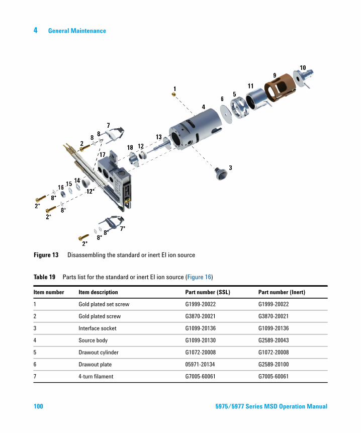
4 General Maintenance
Figure 13 Disassembling the standard or inert EI ion source
100
for the standard or inert EI ion source (Figure 16)
Table 19 Parts listItem number Item description Part number (SSL) Part number (Inert)
1 Gold plated set screw G1999-20022 G1999-20022
2 Gold plated screw G3870-20021 G3870-20021
3 Interface socket G1099-20136 G1099-20136
4 Source body G1099-20130 G2589-20043
5 Drawout cylinder G1072-20008 G1072-20008
6 Drawout plate 05971-20134 G2589-20100
7 4-turn filament G7005-60061 G7005-60061
5975/5977 Series MSD Operation Manual
General Maintenance 4
8 Spring washer and flat washer 3050-1374 and 3050-0982 3050-1374 and 3050-0982
9 Lens insulator G3170-20530 G3170-20530
10 Entrance lens G3170-20126 G3170-20126
11 Ion focus lens 05971-20143 05971-20143
12 Repeller insulator G1099-20133 G1099-20133
13 Repeller G3870-60172 G3870-60173
14 Flat washer 3050-0627 3050-0627
15 Belleville spring washer 3050-1301 3050-1301
16 Repeller nut 0535-0071 0535-0071
17 Source heater block assembly G3870-60180 G3870-60179
18 Repeller block insert G3870-20135 G3870-20135
Table 19 Parts list for the standard or inert EI ion source (Figure 16) (continued)
Item number Item description Part number (SSL) Part number (Inert)
5975/5977 Series MSD Operation Manual 101
4 General Maintenance
To Disassemble the Extractor EI Ion Source
102
Materials needed
• Gloves, clean, lint-free
• Large (8650-0030)
• Small (8650-0029)
• Hex ball driver, 1.5 mm (8710-1570)
• Hex ball driver, 2.0 mm (8710-1804)
• Wrench, open-end, 10 mm (8710-2353)
Procedure
1 Remove the ion source. See “To Remove the EI Ion Source” on page 96.
2 Remove the filaments by removing the two gold plated screws and separating the filaments from the source. See Figure 14 on page 103.
3 Loosen the two gold plated screws on the source heater block assembly, and separate the repeller assembly from the source body. The repeller assembly includes the source heater block assembly, repeller, and related parts.
4 Remove the gold plated setscrews from the side of the source body.
5 Pull the entrance lens and ion focus lens to remove them from the source body.
6 Remove the extractor lens and insulator.
7 Separate the entrance lens and ion focus lens from the lens insulator.
8 Remove the repeller nut, washers, and insulators from the source heater block assembly, then remove the repeller.
5975/5977 Series MSD Operation Manual
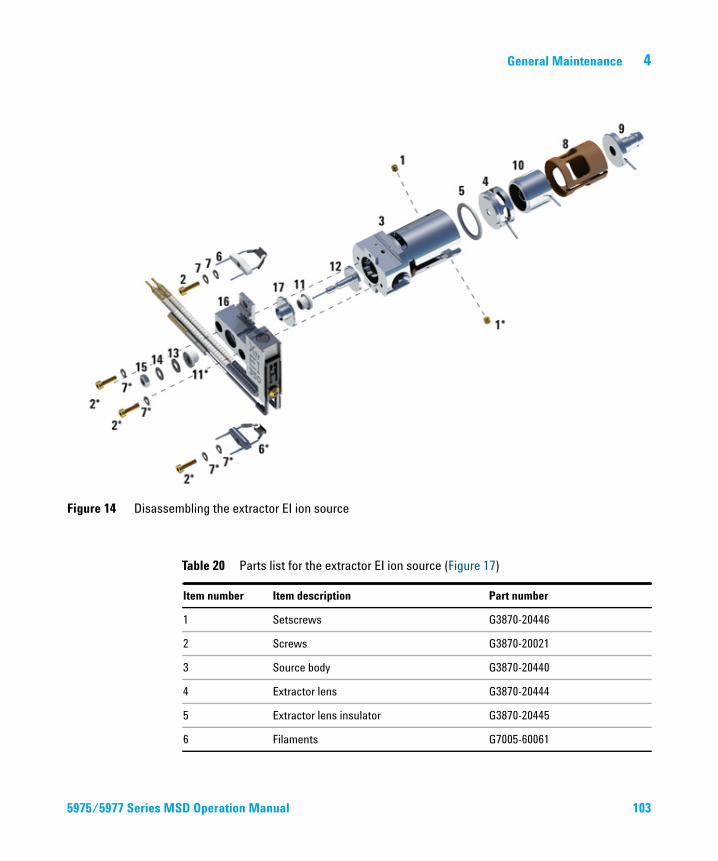
General Maintenance 4
Figure 14 Disassembling the extractor EI ion source
5975/5977 Series M
Table 20 Parts list for the extractor EI ion source (Figure 17)
Item number Item description Part number
1 Setscrews G3870-20446
2 Screws G3870-20021
3 Source body G3870-20440
4 Extractor lens G3870-20444
5 Extractor lens insulator G3870-20445
6 Filaments G7005-60061
SD Operation Manual 103
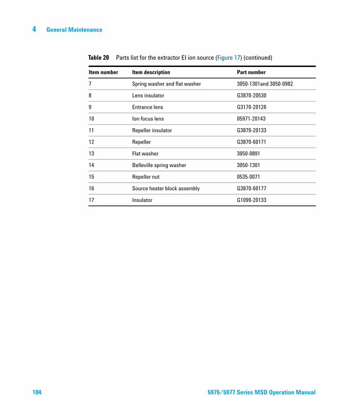
104
4 General Maintenance
7 Spring washer and flat washer 3050-1301and 3050-0982
8 Lens insulator G3870-20530
9 Entrance lens G3170-20126
10 Ion focus lens 05971-20143
11 Repeller insulator G3870-20133
12 Repeller G3870-60171
13 Flat washer 3050-0891
14 Belleville spring washer 3050-1301
15 Repeller nut 0535-0071
16 Source heater block assembly G3870-60177
17 Insulator G1099-20133
Table 20 Parts list for the extractor EI ion source (Figure 17) (continued)
Item number Item description Part number
5975/5977 Series MSD Operation Manual
General Maintenance 4
To Clean the EI Ion Source
5975/5977 Series M
Materials needed
• Abrasive paper (5061-5896)
• Alumina abrasive powder (8660-0791)
• Aluminum foil, clean
• Cloths, clean (05980-60051)
• Cotton swabs (5080-5400)
• Glass beakers, 500 mL
• Gloves, clean, lint-free
• Large (8650-0030)
• Small (8650-0029)
• Solvents
• Acetone, reagent grade
• Methanol, reagent grade
• Methylene chloride, reagent grade
• Ultrasonic bath
Preparation
1 Disassemble the ion source. See “To Disassemble the Standard or Inert EI Ion Source” on page 99 or “To Disassemble the Extractor EI Ion Source” on page 102.
2 Collect the following parts to be cleaned for a standard or inert EI ion source: (See Figure 15 on page 107.)
• Repeller
• Interface socket
• Source body
• Drawout plate
• Drawout cylinder
• Ion focus lens
• Entrance lens
SD Operation Manual 105
106
4 General Maintenance
3 Collect the following parts to be cleaned for an extractor EI ion source: (See Figure 15 on page 107.)
• Repeller
• Insulator
• Source body
• Extractor lens
• Ion focus lens
• Entrance lens
These are the parts that contact the sample or ion beam. The other parts normally should not require cleaning.
CAUTION If insulators are dirty, clean them with a cotton swab dampened with reagent-grade
methanol. If that does not clean the insulators, replace them. Do not abrasively or
ultrasonically clean the insulators.
5975/5977 Series MSD Operation Manual
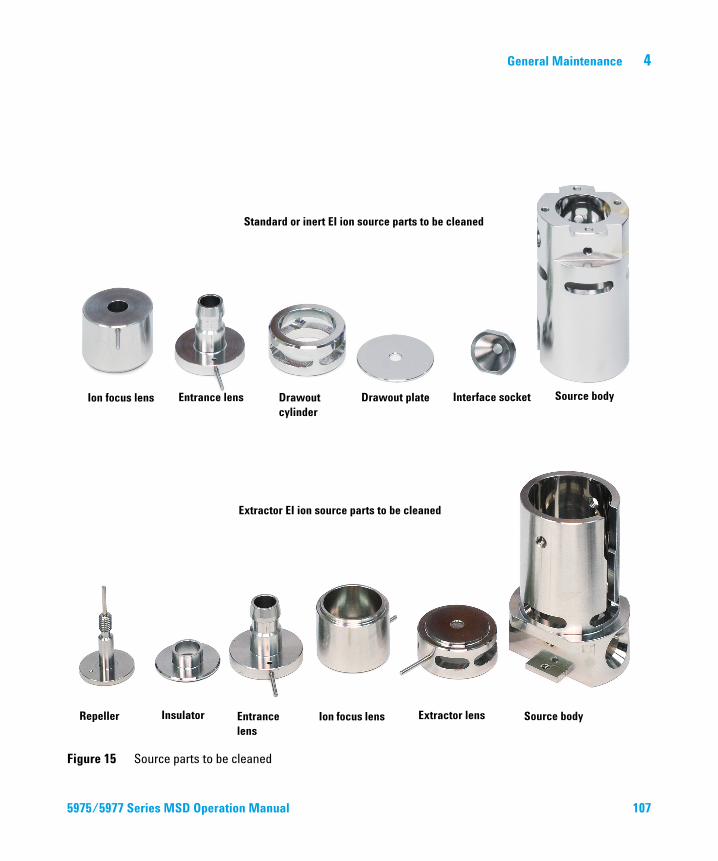
General Maintenance 4
5975/5977 Series M
Figure 15 Source parts to be cleaned
Ion focus lens Entrance lens Drawout cylinder
Drawout plate Interface socket Source body
Standard or inert EI ion source parts to be cleaned
Extractor EI ion source parts to be cleaned
Repeller Insulator Entrance lens
Ion focus lens Extractor lens Source body
SD Operation Man
ual 107
108
4 General Maintenance
Procedure
The filaments, source heater assembly, and insulators cannot be cleaned
CAUTIONultrasonically. Replace these components if major contamination occurs.1 If the contamination is serious, such as an oil backflow into the analyzer, seriously consider replacing the contaminated parts.
2 Abrasively clean the surfaces that contact the sample or ion beam.
Use an abrasive slurry of alumina powder and reagent-grade methanol on a cotton swab. Use enough force to remove all discolorations. Polishing the parts is not necessary; small scratches will not harm performance. Also abrasively clean the discolorations where electrons from the filaments enter the source body.
3 Rinse away all abrasive residue with reagent-grade methanol.
Ensure all abrasive residue is rinsed before ultrasonic cleaning. If the methanol becomes cloudy or contains visible particles, rinse again three times.
4 Separate the parts that were abrasively cleaned from the parts that were not abrasively cleaned.
5 Ultrasonically clean the parts (each group separately) for 15 minutes. For dirty parts, use all three solvents in the order shown, cleaning 15 minutes with each of the following solvents:
• Methylene chloride (reagent-grade)
• Acetone (reagent-grade)
• Methanol (reagent-grade)
For routine cleaning, cleaning with methanol is sufficient.
All of these solvents are hazardous. Work in a fume hood and take all appropriate
WARNINGprecautions.6 Place the parts in a clean beaker. Loosely cover the beaker with clean aluminum foil (dull side down).
7 Dry the cleaned parts in an oven at 100 °C for 5–6 minutes.
5975/5977 Series MSD Operation Manual
General Maintenance 4
WARNING Let the parts cool before you handle them.
NOTE Take care to avoid recontaminating cleaned and dried parts. Put on new, clean gloves
before handling the parts. Do not set the cleaned parts on a dirty surface. Set them only
on clean, lint-free cloths.
5975/5977 Series MSD Operation Manual 109
4 General Maintenance
To Assemble a Standard or Inert EI Ion Source
110
Materials needed
• Gloves, clean, lint-free
• Large (8650-0030)
• Small (8650-0029)
• Hex ball driver, 1.5 mm (8710-1570)
• Hex ball driver, 2.0 mm (8710-1804)
• Wrench, open-end, 10 mm (8710-2353)
Procedure
1 Assemble the repeller assembly.
a Install the repeller block insert into the source heater block assembly. (See Figure 16 on page 111.)
b Install the repeller insulators into the source heater block assembly and repeller block insert.
c Install the repeller through the repeller insulators, then put the flat washer followed by the belleville spring washer onto the end of the repeller shaft and secure finger tight with the repeller nut.
2 Insert the drawout plate and the drawout cylinder into the source body. (See Figure 16 on page 111.)
3 Assemble the ion focus lens, entrance lens, and lens insulators.
4 Slide these assembled parts into the source body.
5 Install the setscrew that holds the lenses in place.
CAUTION Do not overtighten the repeller nut or the ceramic repeller insulators will break when
the source heats up. The nut should only be finger-tight.
6 Install the interface socket.
7 Attach the repeller assembly to the source body using the two gold plated screws and spring washers.
8 Install the filaments using the two gold plated screws and spring washers.
5975/5977 Series MSD Operation Manual
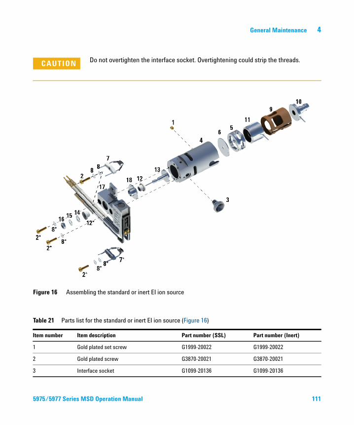
General Maintenance 4
CAUTION Do not overtighten the interface socket. Overtightening could strip the threads.
Figure 16 Assembling the standard or inert EI ion source
5975/5977 Series M
for the standard or inert EI ion source (Figure 16)
Table 21 Parts listItem number Item description Part number (SSL) Part number (Inert)
1 Gold plated set screw G1999-20022 G1999-20022
2 Gold plated screw G3870-20021 G3870-20021
3 Interface socket G1099-20136 G1099-20136
SD Operation Manual 111
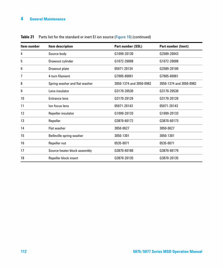
4 General Maintenance
4 Source body G1099-20130 G2589-20043
5 Drawout cylinder G1072-20008 G1072-20008
6 Drawout plate 05971-20134 G2589-20100
7 4-turn filament G7005-60061 G7005-60061
8 Spring washer and flat washer 3050-1374 and 3050-0982 3050-1374 and 3050-0982
9 Lens insulator G3170-20530 G3170-20530
10 Entrance lens G3170-20126 G3170-20126
11 Ion focus lens 05971-20143 05971-20143
12 Repeller insulator G1099-20133 G1099-20133
13 Repeller G3870-60172 G3870-60173
14 Flat washer 3050-0627 3050-0627
15 Belleville spring washer 3050-1301 3050-1301
16 Repeller nut 0535-0071 0535-0071
17 Source heater block assembly G3870-60180 G3870-60179
18 Repeller block insert G3870-20135 G3870-20135
Table 21 Parts list for the standard or inert EI ion source (Figure 16) (continued)
Item number Item description Part number (SSL) Part number (Inert)
112 5975/5977 Series MSD Operation Manual
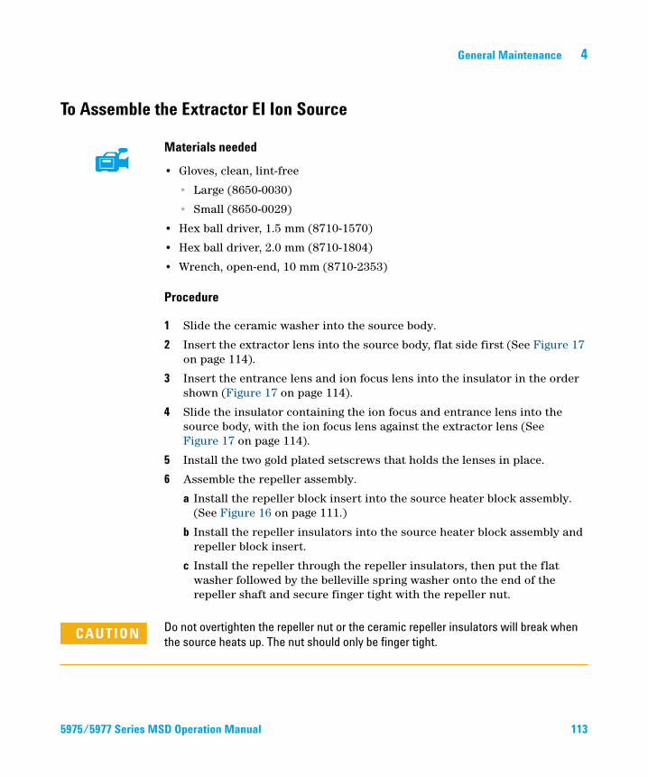
General Maintenance 4
To Assemble the Extractor EI Ion Source
5975/5977 Series M
Materials needed
• Gloves, clean, lint-free
• Large (8650-0030)
• Small (8650-0029)
• Hex ball driver, 1.5 mm (8710-1570)
• Hex ball driver, 2.0 mm (8710-1804)
• Wrench, open-end, 10 mm (8710-2353)
Procedure
1 Slide the ceramic washer into the source body.
2 Insert the extractor lens into the source body, flat side first (See Figure 17 on page 114).
3 Insert the entrance lens and ion focus lens into the insulator in the order shown (Figure 17 on page 114).
4 Slide the insulator containing the ion focus and entrance lens into the source body, with the ion focus lens against the extractor lens (See Figure 17 on page 114).
5 Install the two gold plated setscrews that holds the lenses in place.
6 Assemble the repeller assembly.
a Install the repeller block insert into the source heater block assembly. (See Figure 16 on page 111.)
b Install the repeller insulators into the source heater block assembly and repeller block insert.
c Install the repeller through the repeller insulators, then put the flat washer followed by the belleville spring washer onto the end of the repeller shaft and secure finger tight with the repeller nut.
CAUTION Do not overtighten the repeller nut or the ceramic repeller insulators will break when
the source heats up. The nut should only be finger tight.
SD Operation Manual 113
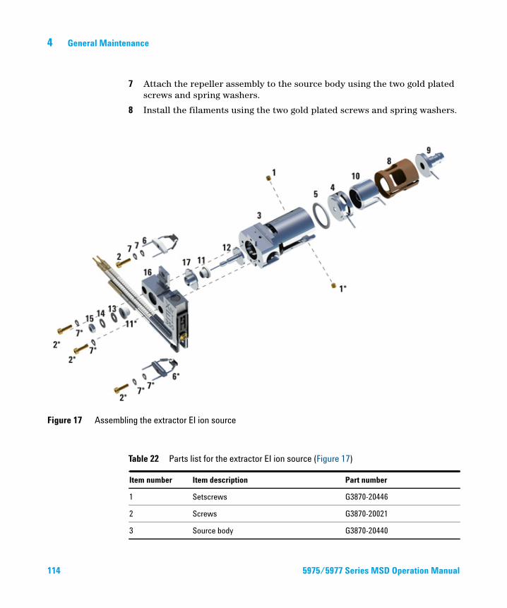
114
4 General Maintenance
7 Attach the repeller assembly to the source body using the two gold plated screws and spring washers.
8 Install the filaments using the two gold plated screws and spring washers.
Figure 17 Assembling the extractor EI ion source
Table 22 Parts list for the extractor EI ion source (Figure 17)
Item number Item description Part number
1 Setscrews G3870-20446
2 Screws G3870-20021
3 Source body G3870-20440
5975/5977 Series MSD Operation Manual
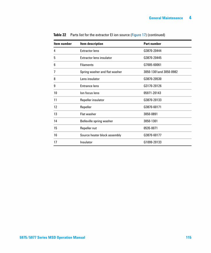
General Maintenance 4
5975/5977 Series M
4 Extractor lens G3870-20444
5 Extractor lens insulator G3870-20445
6 Filaments G7005-60061
7 Spring washer and flat washer 3050-1301and 3050-0982
8 Lens insulator G3870-20530
9 Entrance lens G3170-20126
10 Ion focus lens 05971-20143
11 Repeller insulator G3870-20133
12 Repeller G3870-60171
13 Flat washer 3050-0891
14 Belleville spring washer 3050-1301
15 Repeller nut 0535-0071
16 Source heater block assembly G3870-60177
17 Insulator G1099-20133
Table 22 Parts list for the extractor EI ion source (Figure 17) (continued)
Item number Item description Part number
SD Operation Manual 115
4 General Maintenance
To Replace a Filament in an EI Ion Source
116
Materials needed
• Filament assembly (G7005-60061)
• Gloves, clean, lint-free
• Large (8650-0030)
• Small (8650-0029)
• Hex ball driver, 1.5-mm (8710-1570)
Procedure
1 Vent the MSD. See “Venting the MSD” on page 66.
WARNING The analyzer operates at high temperatures. Do not touch any part until you are sure it is cool.
2 Open the analyzer chamber. See “To Pump Down the MS” on page 79.
3 Remove the ion source. See “To Remove the EI Ion Source” on page 96.
4 Remove the gold plated screw and washer for the filament(s).
5975/5977 Series MSD Operation Manual
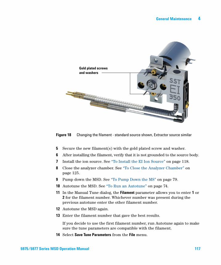
General Maintenance 4
5975/5977 Series M
5 Secure the new filament(s) with the gold plated screw and washer.
6 After installing the filament, verify that it is not grounded to the source body.
7 Install the ion source. See “To Install the EI Ion Source” on page 118.
8 Close the analyzer chamber. See “To Close the Analyzer Chamber” on page 125.
9 Pump down the MSD. See “To Pump Down the MS” on page 79.
10 Autotune the MSD. See “To Run an Autotune” on page 74.
11 In the Manual Tune dialog, the Filament parameter allows you to enter 1 or 2 for the filament number. Whichever number was present during the previous autotune enter the other filament number.
12 Autotune the MSD again.
13 Enter the filament number that gave the best results.
If you decide to use the first filament number, run Autotune again to make sure the tune parameters are compatible with the filament.
14 Select Save Tune Parameters from the File menu.
Figure 18 Changing the filament - standard source shown, Extractor source similar
Gold plated screws and washers
SD Operation
Manual 117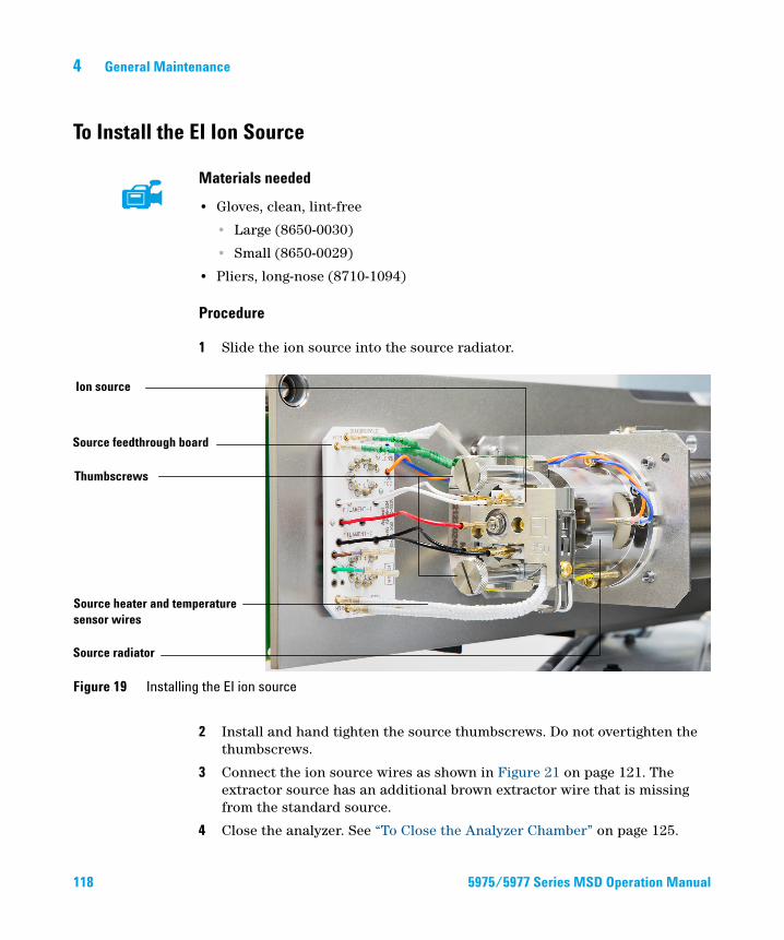
4 General Maintenance
To Install the EI Ion Source
118
Materials needed
• Gloves, clean, lint-free
• Large (8650-0030)
• Small (8650-0029)
• Pliers, long-nose (8710-1094)
Procedure
1 Slide the ion source into the source radiator.
Figure 19 Installing the EI ion source
Source feedthrough board
Ion source
Thumbscrews
Source heater and temperature sensor wires
Source radiator
2 Install and hand tighten the source thumbscrews. Do not overtighten the thumbscrews.
3 Connect the ion source wires as shown in Figure 21 on page 121. The extractor source has an additional brown extractor wire that is missing from the standard source.
4 Close the analyzer. See “To Close the Analyzer Chamber” on page 125.
5975/5977 Series MSD Operation Manual
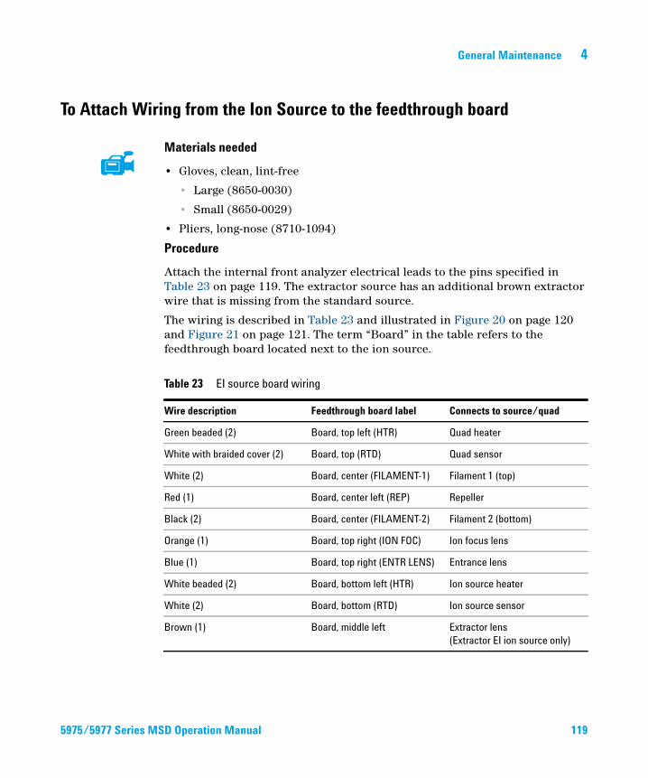
General Maintenance 4
To Attach Wiring from the Ion Source to the feedthrough board
5975/5977 Series M
Materials needed
• Gloves, clean, lint-free
• Large (8650-0030)
• Small (8650-0029)
• Pliers, long-nose (8710-1094)
Procedure
Attach the internal front analyzer electrical leads to the pins specified in Table 23 on page 119. The extractor source has an additional brown extractor wire that is missing from the standard source.
The wiring is described in Table 23 and illustrated in Figure 20 on page 120 and Figure 21 on page 121. The term “Board” in the table refers to the feedthrough board located next to the ion source.
Table 23 EI source board wiring
Wire description Feedthrough board label Connects to source/quad
Green beaded (2) Board, top left (HTR) Quad heater
White with braided cover (2) Board, top (RTD) Quad sensor
White (2) Board, center (FILAMENT-1) Filament 1 (top)
Red (1) Board, center left (REP) Repeller
Black (2) Board, center (FILAMENT-2) Filament 2 (bottom)
Orange (1) Board, top right (ION FOC) Ion focus lens
Blue (1) Board, top right (ENTR LENS) Entrance lens
White beaded (2) Board, bottom left (HTR) Ion source heater
White (2) Board, bottom (RTD) Ion source sensor
Brown (1) Board, middle left Extractor lens
(Extractor EI ion source only)
SD Operation Manual 119
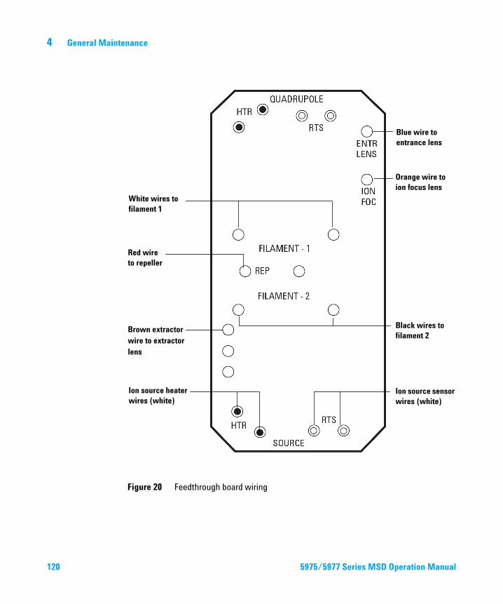
120
4 General Maintenance
Figure 20 Feedthrough board wiring
White wires to filament 1
Red wire to repeller
Black wires to filament 2
Ion source heater wires (white)
Blue wire to entrance lens
Orange wire to ion focus lens
Ion source sensor wires (white)
Brown extractor wire to extractor lens
5975/5977 Series MSD
Operation Manual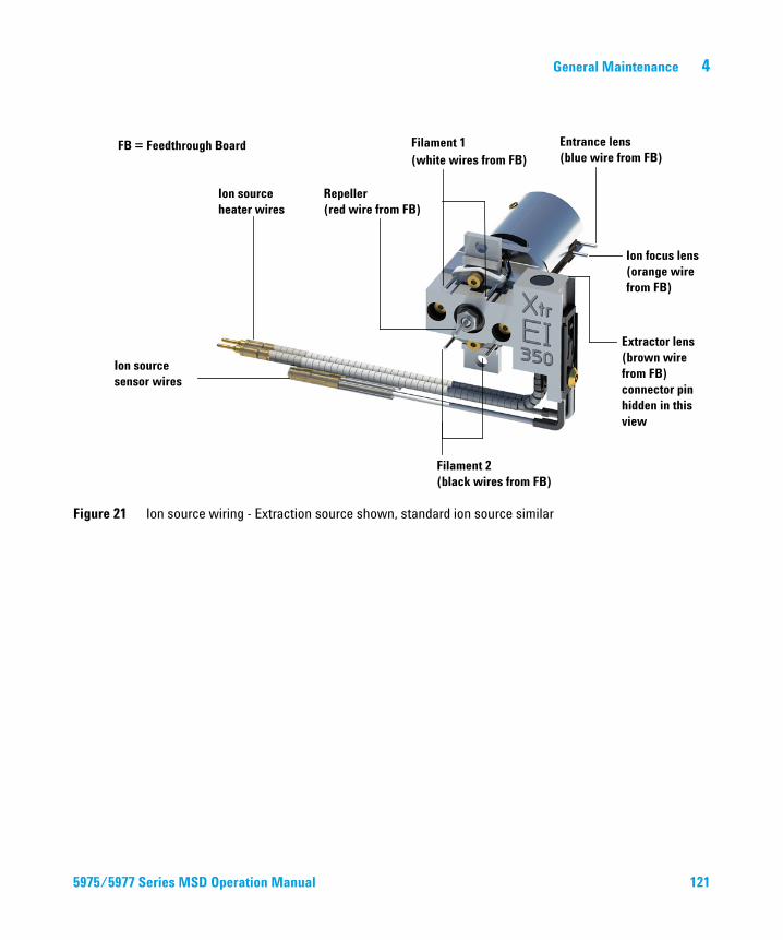
General Maintenance 4
Figure 21 Ion source wiring - Extraction source shown, standard ion source similar
FB = Feedthrough Board
Ion source heater wires
Ion focus lens (orange wire from FB)
Entrance lens (blue wire from FB)
Filament 2 (black wires from FB)
Ion source sensor wires
Extractor lens (brown wire from FB) connector pin hidden in this view
Filament 1 (white wires from FB)
Repeller (red wire from FB)
5975/
5977 Series MSD Operation Manual 121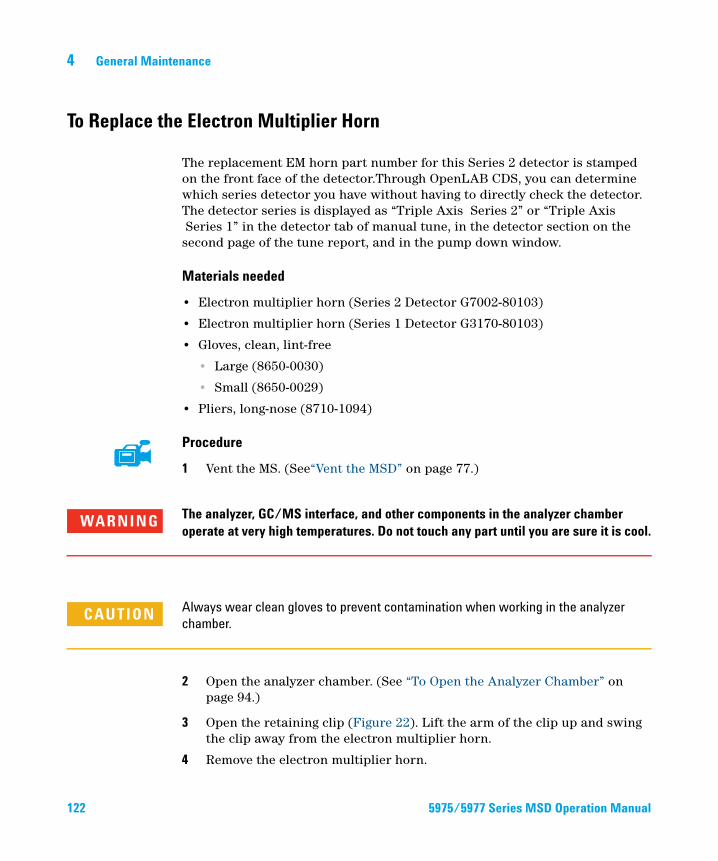
4 General Maintenance
To Replace the Electron Multiplier Horn
122
The replacement EM horn part number for this Series 2 detector is stamped on the front face of the detector.Through OpenLAB CDS, you can determine which series detector you have without having to directly check the detector. The detector series is displayed as “Triple Axis Series 2” or “Triple Axis Series 1” in the detector tab of manual tune, in the detector section on the second page of the tune report, and in the pump down window.
Materials needed
• Electron multiplier horn (Series 2 Detector G7002-80103)
• Electron multiplier horn (Series 1 Detector G3170-80103)
• Gloves, clean, lint-free
• Large (8650-0030)
• Small (8650-0029)
• Pliers, long-nose (8710-1094)
Procedure
1 Vent the MS. (See“Vent the MSD” on page 77.)
WARNING The analyzer, GC/MS interface, and other components in the analyzer chamber operate at very high temperatures. Do not touch any part until you are sure it is cool.
CAUTION Always wear clean gloves to prevent contamination when working in the analyzer
chamber.
2 Open the analyzer chamber. (See “To Open the Analyzer Chamber” on page 94.)
3 Open the retaining clip (Figure 22). Lift the arm of the clip up and swing the clip away from the electron multiplier horn.
4 Remove the electron multiplier horn.
5975/5977 Series MSD Operation Manual
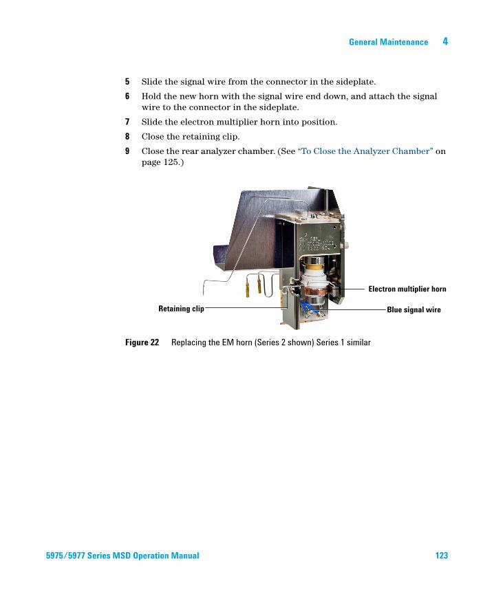
General Maintenance 4
5975/5977 Series M
5 Slide the signal wire from the connector in the sideplate.
6 Hold the new horn with the signal wire end down, and attach the signal wire to the connector in the sideplate.
7 Slide the electron multiplier horn into position.
8 Close the retaining clip.
9 Close the rear analyzer chamber. (See “To Close the Analyzer Chamber” on page 125.)
Figure 22 Replacing the EM horn (Series 2 shown) Series 1 similar
Retaining clip
Electron multiplier horn
Blue signal wire
SD Operation Manual 123
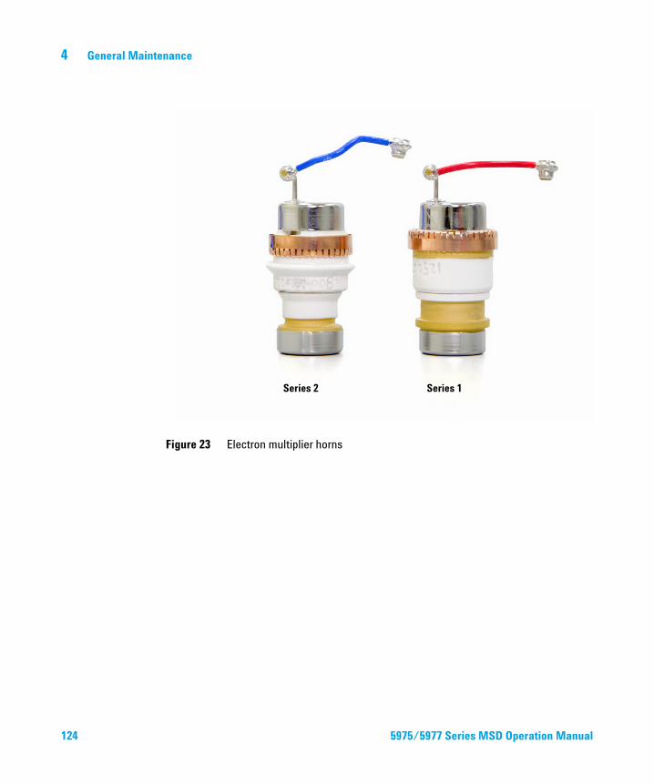
124
4 General Maintenance
Figure 23 Electron multiplier horns
Series 1Series 2
5975/
5977 Series MSD Operation Manual
General Maintenance 4
To Close the Analyzer Chamber
5975/5977 Series M
Procedure
1 Ensure all the internal analyzer electrical leads are correctly attached. Wiring is not the same for both the EI and CI ion sources. The wiring is described in “To Attach Wiring from the Ion Source to the feedthrough board” on page 119.
Check the side plate O-ring.
Make sure the O-ring has a very light coat of Apiezon L high vacuum grease. If the O-ring is very dry, it may not seal well. If the O-ring looks shiny, it has too much grease on it. (Refer to the 5977 Series MS Troubleshooting and Maintenance Manual for lubricating instructions.)
Do not force the analyzer door when closing, or you may damage the collision cell or
CAUTIONquadrupole.2 Swing the analyzer side plate closed.
The post-filter on the exit side of the quad helps to position the collision cell when the analyzer door is closed. When closing, the door should give minimal resistance while the quad is reseating the collision cell. The analyzer should slide into place with minimal pressure.
3 Ensure the vent valve is closed.
4 If hydrogen or other flammable or toxic substance is used for carrier gas, gently hand-tighten the top thumbscrew on the front analyzer side plate.
5 Pump down the MS. (See “To Pump Down the MS” on page 79.)
The top thumbscrew must be fastened if hydrogen (or other hazardous gas) is being
WARNINGused as the GC carrier gas. In the unlikely event of an explosion, it may prevent the side plate from opening.Do not overtighten the thumbscrew; it can cause air leaks or prevent successful
CAUTIONpumpdown. Do not use a screwdriver to tighten the thumbscrew.SD Operation Manual 125
126
4 General Maintenance
6 Once the MS has pumped down, close the left analyzer cover and replace the window cover.
7 Tune the MS.
5975/5977 Series MSD Operation Manual

Agilent Technologies
© Agilent Technologies, Inc. 2015,
Printed in USA August 2015
*G7077-90014*
G7077-90014