Agilent 5973 MS User Manual
162
Agilent Technologies Agilent 5975 Series MSD Operation Manual
-
Upload
mohammed-nabil-ahmed -
Category
Documents
-
view
641 -
download
5
description
Agilent MSD manual for MS5973
Transcript of Agilent 5973 MS User Manual
7/14/2019 Agilent 5973 MS User Manual
http://slidepdf.com/reader/full/agilent-5973-ms-user-manual 1/162
Agilent Technologies
Agilent 5975
Series MSD
Operation Manual
7/14/2019 Agilent 5973 MS User Manual
http://slidepdf.com/reader/full/agilent-5973-ms-user-manual 2/162
2 5975 Series MSD Operation Manual
Notices© Agilent Technologies, Inc. 2012
No part of this manual may be reproduced in
any form or by any means (including elec-
tronic storage and retrieval or translation
into a foreign language) without prior agree-
ment and written consent from Agilent
Technologies, Inc. as governed by United
States and international copyright laws.
Manual Part Number
G3170-90036
Edition
Fourth edition, June 2012
Replaces G3170-90030
Printed in USA
Agilent Technologies, Inc.
5301 Stevens Creek Boulevard
Santa Clara, CA 95052
Warranty
The material contained in this docu-ment is provided “as is,” and is sub-ject to being changed, without notice,in future editions. Further, to the max-imum extent permitted by applicablelaw, Agilent disclaims all warranties,
either express or implied, with regardto this manual and any informationcontained herein, including but notlimited to the implied warranties ofmerchantability and fitness for a par-ticular purpose. Agilent shall not beliable for errors or for incidental orconsequential damages in connec-tion with the furnishing, use, or per-formance of this document or of anyinformation contained herein. ShouldAgilent and the user have a separatewritten agreement with warrantyterms covering the material in thisdocument that conflict with theseterms, the warranty terms in the sep-arate agreement shall control.
Safety Notices
CAUTION
A CAUTION notice denotes a
hazard. It calls attention to an
operating procedure, practice, orthe like that, if not correctly
performed or adhered to, could
result in damage to the product or
loss of important data. Do not
proceed beyond a CAUTION notice
until the indicated conditions are
fully understood and met.
WARNING
A WARNING notice denotes a
hazard. It calls attention to an
operating procedure, practice, or
the like that, if not correctly
performed or adhered to, could
result in personal injury or death.
Do not proceed beyond a
WARNING notice until the
indicated conditions are fully
understood and met.
7/14/2019 Agilent 5973 MS User Manual
http://slidepdf.com/reader/full/agilent-5973-ms-user-manual 3/162
5975 Series MSD Operation Manual 3
About This ManualThis manual contains information for operating and
maintaining the Agilent 5975 Series Gas Chromatograph/Mass
Selective Detector (GC/MSD) system.
1 “Introduction”
Chapter 1 describes general information about the 5975 Series
MSDs, including a hardware description, general safety
warnings, and hydrogen safety information.
2 “Installing GC Columns”
Chapter 2 shows you how to prepare a capillary column for use
with the MSD, install it in the GC oven, and connect it to the
MSD using the GC/MSD interface.
3 “Operating in Electron Impact (EI) Mode”
Chapter 3 describes basic tasks such as setting temperatures,
monitoring pressures, tuning, venting, and pumpdown. Much of
the information in this chapter also applies to CI operation.
4 “Operating in Chemical Ionization (CI) Mode”
Chapter 4 describes additional tasks necessary to operate in CI
mode.
5 “General Maintenance”
Chapter 5 describes maintenance procedures common to both
EI and CI instruments.
6 “CI Maintenance”
Chapter 6 describes maintenance procedures unique to CI
MSDs.
A “Chemical Ionization Theory”
Appendix A is an overview of chemical ionization theory.
7/14/2019 Agilent 5973 MS User Manual
http://slidepdf.com/reader/full/agilent-5973-ms-user-manual 4/162
4 5975 Series MSD Operation Manual
Online User InformationNow your Agilent instrument documentation is in one place, at
your fingertips.
The Instrument Utilities DVD that ships with your instrument
provides an extensive collection of online help, videos, and
books for the Agilent 7890A GC, 7820A GC, 6890N GC, 6850 GC, 5975T
LTM GC/MS, 7693A ALS, and the 7683B ALS. Included are localized
versions of the information you need most, such as:
• Getting Familiar documentation• Safety and Regulatory guides• Site Preparation checklists• Installation information• Operating guides• Maintenance information• Troubleshooting details
7/14/2019 Agilent 5973 MS User Manual
http://slidepdf.com/reader/full/agilent-5973-ms-user-manual 5/162
5975 Series MSD Operation Manual 5
Contents
1 Introduction
5975 MSD Version 10
Abbreviations Used 11
The 5975 Series MSD 13
CI MSD Hardware Description 15
Important Safety Warnings 17
Hydrogen Safety 19
GC precautions 19
Safety and Regulatory Certifications 24
Cleaning/Recycling the Product 27
Liquid Spillage 27
Moving or Storing the MSD 27
2 Installing GC Columns
Columns 30
To reconfigure a 6850 GC column on its basket 32
To prepare a capillary column for installation 37
To install a capillary column in a split/splitless inlet 39
To condition a capillary column 41
To install a capillary column in the GC/MSD interface 43
Agilent 7890A and 7820A, and 6890 GCs 43
6850 GC 45
3 Operating in Electron Impact (EI) Mode
Operating the MSD from the Data System 51
7/14/2019 Agilent 5973 MS User Manual
http://slidepdf.com/reader/full/agilent-5973-ms-user-manual 6/162
5975 Series MSD Operation Manual 6
Operating the MSD from the LCP 51Modes of operation 51
LCP Status Messages 53
ChemStation Loading <timestamp> 53
Executing <type>tune 53
Instrument Available <timestamp> 53
Loading Method <method name> 53Loading MSD Firmware 53
Loading OS 54
<method> Complete <timestamp> 54
Method Loaded <method name> 54
MS locked by <computer name> 54
Press Sideplate 54
Run: <method> Acquiring <datafile> 54
To view system status during startup 54
LCP Menus 55
The EI GC/MSD Interface 58
Before You Turn On the MSD 60
Pumping Down 61
Controlling Temperatures 61
Controlling Column Flow 62
Venting the MSD 63
To view MSD analyzer temperature and vacuum status 64
To set monitors for MSD temperature and vacuum status 66
To set the MSD analyzer temperatures 67
To set the GC/MSD interface temperature from the
ChemStation 69
To monitor high vacuum pressure 71
7/14/2019 Agilent 5973 MS User Manual
http://slidepdf.com/reader/full/agilent-5973-ms-user-manual 7/162
5975 Series MSD Operation Manual 7
To measure column flow linear velocity 73
To confirm column flow 74
To tune the MSD 75
To verify system performance 76
High-Mass Testing (5975 Series MSDs) 77
To remove the MSD covers 80
To vent the MSD 82
To open the analyzer chamber 84
To close the analyzer chamber 87
To pump down the MSD 91
To move or store the MSD 93
To set the interface temperature from the GC 95
4 Operating in Chemical Ionization (CI) Mode
General Guidelines 98
The CI GC/MSD Interface 99To Operate the CI MSD 101
To switch from the EI source to the CI source 102
To pump down the CI MSD 103
To set up the software for CI operation 104
To operate the reagent gas flow control module 106
To set up methane reagent gas flow 109
To use other reagent gases 111
To switch from the CI source to the EI source 115
CI Autotune 116
7/14/2019 Agilent 5973 MS User Manual
http://slidepdf.com/reader/full/agilent-5973-ms-user-manual 8/162
5975 Series MSD Operation Manual 8
To perform a PCI autotune (methane only) 118
To perform an NCI autotune (methane reagent gas) 120
To verify PCI performance 122
To verify NCI performance 123
To monitor high vacuum pressure 124
5 General Maintenance
Before Starting 128
Maintaining the Vacuum System 133
6 CI Maintenance
General Information 140To Set Up Your MSD for CI Operation 141
A Chemical Ionization Theory
Chemical Ionization Overview 146
Positive CI Theory 148
Negative CI Theory 155
7/14/2019 Agilent 5973 MS User Manual
http://slidepdf.com/reader/full/agilent-5973-ms-user-manual 9/162
9
Agilent 5975 Series MSD
Operation Manual
Agilent Technologies
1
Introduction
5975 MSD Version 10
Abbreviations Used 11
The 5975 Series MSD 13CI MSD Hardware Description 15
Important Safety Warnings 17
Many internal parts of the MSD carry dangerous voltages 17
Electrostatic discharge is a threat to MSD electronics 17
Many parts are dangerously hot 18
The oil pan under the standard foreline pump can be a fire hazard 18
Hydrogen Safety 19
Dangers unique to GC/MSD operation 20
Hydrogen accumulation in an MSD 20
Precautions 22
Safety and Regulatory Certifications 24
Information 24
Symbols 25
Electromagnetic compatibility 26
Sound emission declaration 26
Cleaning/Recycling the Product 27
Liquid Spillage 27
Moving or Storing the MSD 27
This manual describes the operation, and routine maintenance of the Agilent
Technologies 5975 Series MSD.
7/14/2019 Agilent 5973 MS User Manual
http://slidepdf.com/reader/full/agilent-5973-ms-user-manual 10/162
10 5975 Series MSD Operation Manual
1 Introduction
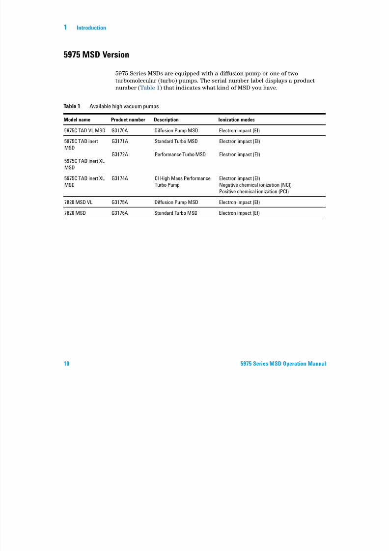
5975 MSD Version
5975 Series MSDs are equipped with a diffusion pump or one of two
turbomolecular (turbo) pumps. The serial number label displays a product
number (Table 1) that indicates what kind of MSD you have.
Table 1 Available high vacuum pumps
Model name Product number Description Ionization modes
5975C TAD VL MSD G3170A Diffusion Pump MSD Electron impact (EI)
5975C TAD inert
MSD
5975C TAD inert XL
MSD
G3171A
G3172A
Standard Turbo MSD
Performance Turbo MSD
Electron impact (EI)
Electron impact (EI)
5975C TAD inert XL
MSD
G3174A CI High Mass Performance
Turbo Pump
Electron impact (EI)
Negative chemical ionization (NCI)
Positive chemical ionization (PCI)
7820 MSD VL G3175A Diffusion Pump MSD Electron impact (EI)
7820 MSD G3176A Standard Turbo MSD Electron impact (EI)
7/14/2019 Agilent 5973 MS User Manual
http://slidepdf.com/reader/full/agilent-5973-ms-user-manual 11/162
Introduction 1
5975 Series MSD Operation Manual 11
Abbreviations Used
The abbreviations in Table 2 are used in discussing this product. They are
collected here for convenience.
Table 2 Abbreviations
Abbreviation Definition
AC Alternating current
ALS Automatic liquid sampler
BFB Bromofluorobenzene (calibrant)
CI Chemical ionization
DC Direct current
DFTPP Decafluorotriphenylphosphine (calibrant)
DIP Direct insertion probe
DP Diffusion pump
EI Electron impact ionization
EM Electron multiplier (detector)
EMV Electron multiplier voltage
EPC Electronic pneumatic control
eV Electron volt
GC Gas chromatograph
HED High-energy dynode (refers to detector and its power supply)
id Inside diameter
LAN Local Area Network
LCP Local control panel (on the MSD)
LTM Low thermal mass
m/z Mass to charge ratio
MFC Mass flow controller
7/14/2019 Agilent 5973 MS User Manual
http://slidepdf.com/reader/full/agilent-5973-ms-user-manual 12/162
12 5975 Series MSD Operation Manual
1 Introduction
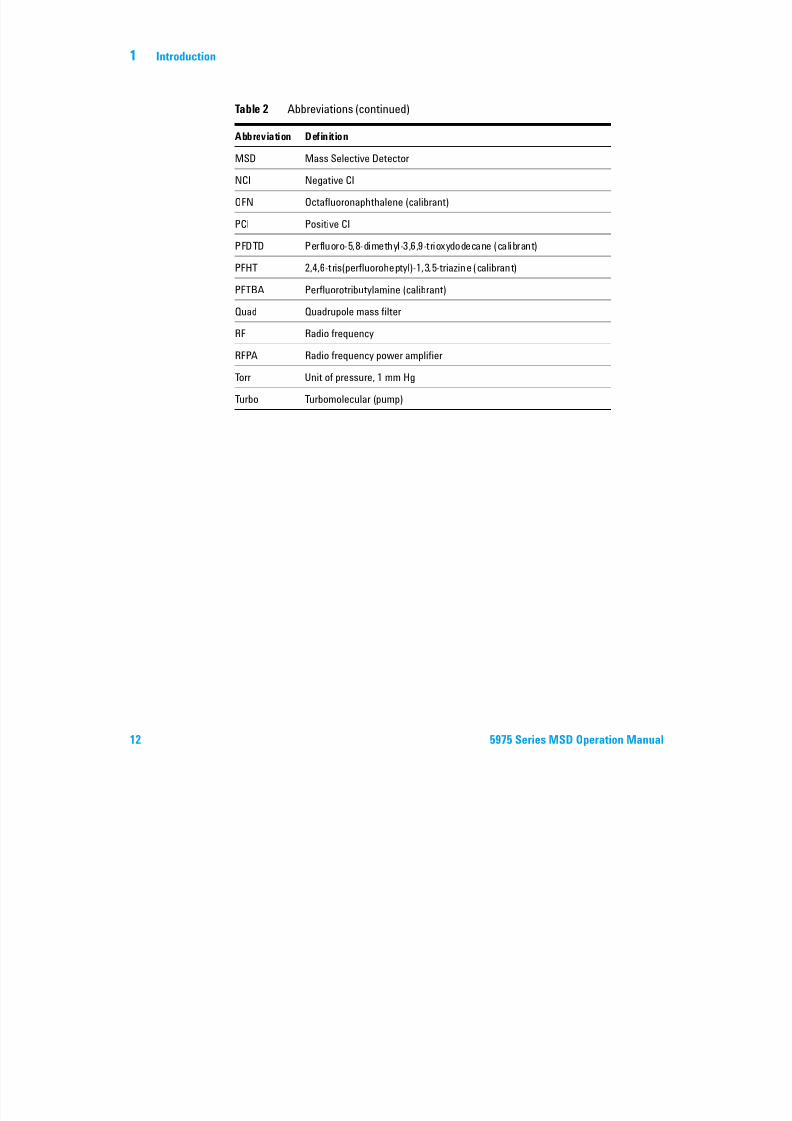
MSD Mass Selective Detector
NCI Negative CI
OFN Octafluoronaphthalene (calibrant)
PCI Positive CI
PFDTD Perfluoro-5,8-dimethyl-3,6,9-trioxydodecane (calibrant)
PFHT 2,4,6-tris(perfluoroheptyl)-1,3,5-triazine (calibrant)
PFTBA Perfluorotributylamine (calibrant)
Quad Quadrupole mass filter
RF Radio frequency
RFPA Radio frequency power amplifier
Torr Unit of pressure, 1 mm Hg
Turbo Turbomolecular (pump)
Table 2 Abbreviations (continued)
Abbreviation Definition
7/14/2019 Agilent 5973 MS User Manual
http://slidepdf.com/reader/full/agilent-5973-ms-user-manual 13/162
Introduction 1
5975 Series MSD Operation Manual 13
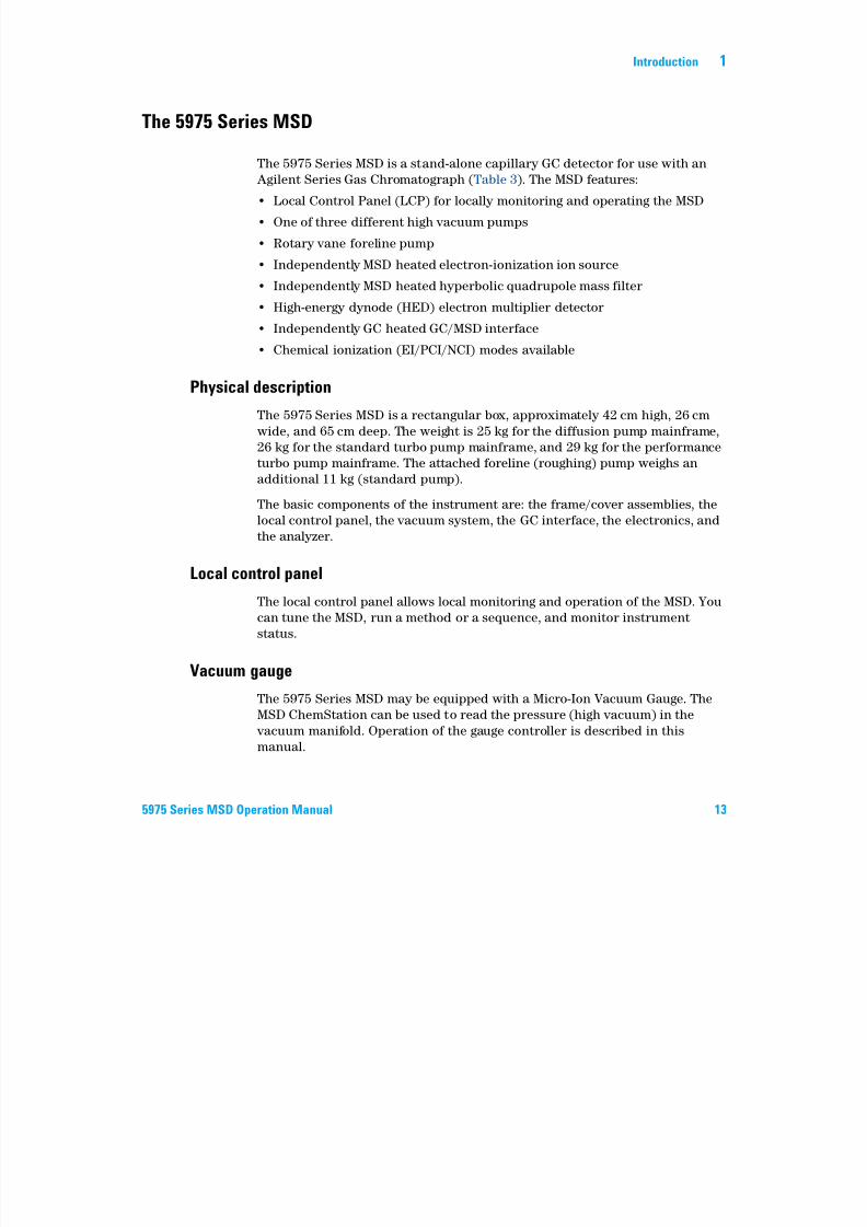
The 5975 Series MSD
The 5975 Series MSD is a stand-alone capillary GC detector for use with an
Agilent Series Gas Chromatograph (Table 3). The MSD features:
• Local Control Panel (LCP) for locally monitoring and operating the MSD
• One of three different high vacuum pumps
• Rotary vane foreline pump
• Independently MSD heated electron-ionization ion source
• Independently MSD heated hyperbolic quadrupole mass filter
• High-energy dynode (HED) electron multiplier detector
• Independently GC heated GC/MSD interface
• Chemical ionization (EI/PCI/NCI) modes available
Physical description
The 5975 Series MSD is a rectangular box, approximately 42 cm high, 26 cm
wide, and 65 cm deep. The weight is 25 kg for the diffusion pump mainframe,
26 kg for the standard turbo pump mainframe, and 29 kg for the performance
turbo pump mainframe. The attached foreline (roughing) pump weighs an
additional 11 kg (standard pump).
The basic components of the instrument are: the frame/cover assemblies, thelocal control panel, the vacuum system, the GC interface, the electronics, and
the analyzer.
Local control panel
The local control panel allows local monitoring and operation of the MSD. You
can tune the MSD, run a method or a sequence, and monitor instrument
status.
Vacuum gauge
The 5975 Series MSD may be equipped with a Micro-Ion Vacuum Gauge. The
MSD ChemStation can be used to read the pressure (high vacuum) in the
vacuum manifold. Operation of the gauge controller is described in this
manual.
7/14/2019 Agilent 5973 MS User Manual
http://slidepdf.com/reader/full/agilent-5973-ms-user-manual 14/162
14 5975 Series MSD Operation Manual
1 Introduction
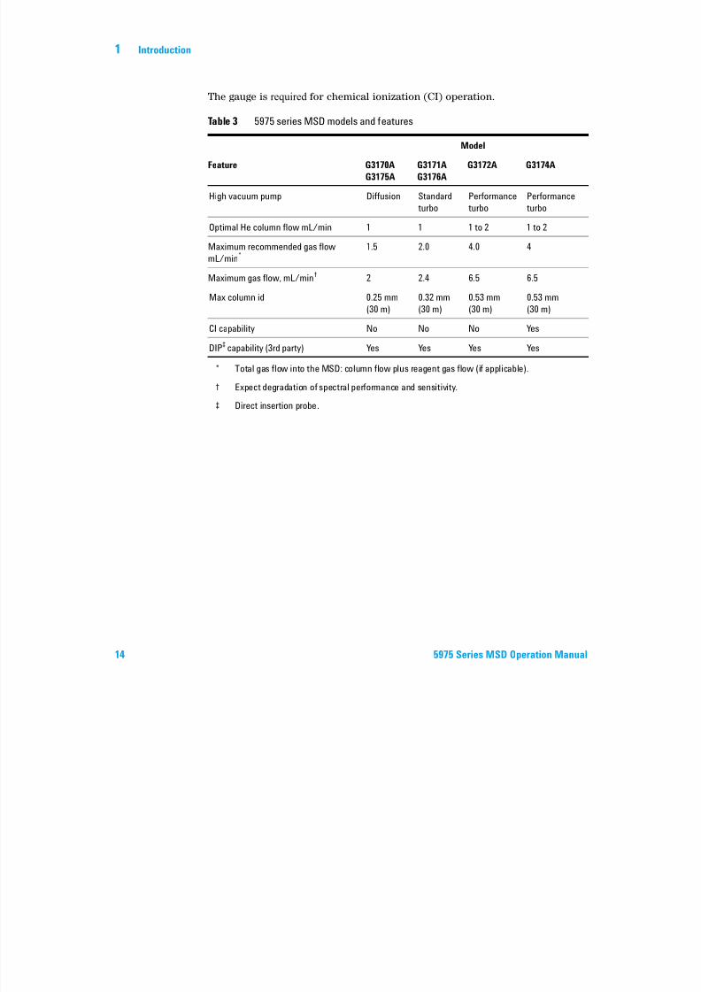
The gauge is required for chemical ionization (CI) operation.
Table 3 5975 series MSD models and features
Model
Feature G3170A
G3175A
G3171A
G3176A
G3172A G3174A
High vacuum pump Diffusion Standard
turbo
Performance
turbo
Performance
turbo
Optimal He column flow mL/min 1 1 1 to 2 1 to 2
Maximum recommended gas flow
mL/min*
* Total gas flow into the MSD: column flow plus reagent gas flow (if applicable).
1.5 2.0 4.0 4
Maximum gas flow, mL/min†
† Expect degradation of spectral performance and sensitivity.
2 2.4 6.5 6.5
Max column id 0.25 mm
(30 m)
0.32 mm
(30 m)
0.53 mm
(30 m)
0.53 mm
(30 m)
CI capability No No No Yes
DIP‡ capability (3rd party)
‡ Direct insertion probe.
Yes Yes Yes Yes
7/14/2019 Agilent 5973 MS User Manual
http://slidepdf.com/reader/full/agilent-5973-ms-user-manual 15/162
Introduction 1
5975 Series MSD Operation Manual 15
CI MSD Hardware Description
Figure 1 is an overview of a typical 5975 GC/MSD system.
The CI hardware allows the 5975 Series MSD to produce high-quality, classical
CI spectra, which include molecular adduct ions. A variety of reagent gases
can be used.
Figure 1 5975 Series GC/MSD system
ALS
7890A GC
CI gas flow module
Local control panel
5975 Series MSD
MSD power switch
GC power switch

7/14/2019 Agilent 5973 MS User Manual
http://slidepdf.com/reader/full/agilent-5973-ms-user-manual 16/162
16 5975 Series MSD Operation Manual
1 Introduction
In this manual, the term “CI MSD” refers to the G3174A MSD and upgraded
G3172A MSDs. It also applies, unless otherwise specified, to the flow modulesfor these instruments.
The 5975 Series CI system adds to the 5975 Series MSD:
• EI/CI GC/MSD interface
• CI ion source and interface tip seal
• Reagent gas flow control module
• Bipolar HED power supply for PCI and NCI operation
A methane/isobutane gas purifier is provided and is required . It removes
oxygen, water, hydrocarbons, and sulfur compounds.
A high vacuum gauge controller (G3397A) is required for CI MSD and is
recommended for EI also.
The MSD CI system has been optimized to achieve the relatively high source
pressure required for CI while still maintaining high vacuum in thequadrupole and detector. Special seals along the f low path of the reagent gas
and very small openings in the ion source keep the source gases in the
ionization volume long enough for the appropriate reactions to occur.
The CI interface has special plumbing for reagent gas. A spring-loaded
insulating seal fits onto the tip of the interface.
Switching back and forth between CI and EI sources takes less than an hour,
although a 1- to 2-hour wait is required to purge the reagent gas lines and bake
out water and other contaminants. Switching from PCI to NCI requires about
2 hours for the ion source to cool.
7/14/2019 Agilent 5973 MS User Manual
http://slidepdf.com/reader/full/agilent-5973-ms-user-manual 17/162
Introduction 1
5975 Series MSD Operation Manual 17
Important Safety WarningsThere are several important safety notices to always keep in mind when using
the MSD.
Many internal parts of the MSD carry dangerous voltages
If the MSD is connected to a power source, even if the power switch is off,
potentially dangerous voltages exist on:
• The wiring between the MSD power cord and the AC power supply, the AC
power supply itself, and the wiring from the AC power supply to the power
switch.
With the power switch on, potentially dangerous voltages also exist on:
• All electronics boards in the instrument.
• The internal wires and cables connected to these boards.• The wires for any heater (oven, detector, inlet, or valve box).
Electrostatic discharge is a threat to MSD electronics
The printed circuit boards in the MSD can be damaged by electrostaticdischarge. Do not touch any of the boards unless it is absolutely necessary. If
you must handle them, wear a grounded wrist strap and take other antistatic
precautions. Wear a grounded wrist strap any time you must remove the MSD
right side cover.
WARNINGAll these parts are shielded by covers. With the covers in place, it should be difficult
to accidentally make contact with dangerous voltages. Unless specifically
instructed to, never remove a cover unless the detector, inlet, or oven are turned off.
WARNINGIf the power cord insulation is frayed or worn, the cord must be replaced. Contact
your Agilent service representative.
7/14/2019 Agilent 5973 MS User Manual
http://slidepdf.com/reader/full/agilent-5973-ms-user-manual 18/162
18 5975 Series MSD Operation Manual
1 Introduction
Many parts are dangerously hot
Many parts of the GC/MSD operate at temperatures high enough to cause
serious burns. These parts include but are not limited to:
• The inlets
• The oven and its contents
• The detector
• The column nuts attaching the column to an inlet or detector
• The valve box
• The foreline pump
Always cool these areas of the system to room temperature before working on
them. They will cool faster if you first set the temperature of the heated zone
to room temperature. Turn the zone off after it has reached the setpoint. If you
must perform maintenance on hot parts, use a wrench and wear gloves.
Whenever possible, cool the part of the instrument that you will bemaintaining before you begin working on it.
The oil pan under the standard foreline pump can be a fire hazard
Oily rags, paper towels, and similar absorbents in the oil pan could ignite and
damage the pump and other parts of the MSD.
WARNINGBe careful when working behind the instrument. During cool-down cycles, the GC
emits hot exhaust which can cause burns.
WARNING The insulation around the inlets, detectors, valve box, and the insulation cups ismade of refractory ceramic fibers. To avoid inhaling fiber particles, we recommend
the following safety procedures: ventilate your work area; wear long sleeves,
gloves, safety glasses, and a disposable dust/mist respirator; dispose of insulation
in a sealed plastic bag; wash your hands with mild soap and cold water after
handling the insulation.
WARNINGCombustible materials (or flammable/non-flammable wicking material) placed
under, over, or around the foreline (roughing) pump constitutes a fire hazard. Keep
the pan clean, but do not leave absorbent material such as paper towels in it.
7/14/2019 Agilent 5973 MS User Manual
http://slidepdf.com/reader/full/agilent-5973-ms-user-manual 19/162
Introduction 1
5975 Series MSD Operation Manual 19
Hydrogen Safety
Hydrogen is a commonly used GC carrier gas. Hydrogen is potentially
explosive and has other dangerous characteristics.
• Hydrogen is combustible over a wide range of concentrations. At
atmospheric pressure, hydrogen is combustible at concentrations from 4%
to 74.2% by volume.
• Hydrogen has the highest burning velocity of any gas.
• Hydrogen has a very low ignition energy.
• Hydrogen that is allowed to expand rapidly from high pressure can
self-ignite.
• Hydrogen burns with a nonluminous flame which can be invisible under
bright light.
GC precautions
When using hydrogen as a carrier gas, remove the large round plastic cover for
the MSD transfer line located on the GC left side panel. In the unlikely event of
an explosion, this cover may dislodge.
WARNINGThe use of hydrogen as a GC carrier gas is potentially dangerous.
WARNING When using hydrogen (H2) as the carrier gas or fuel gas, be aware that hydrogengas can flow into the GC oven and create an explosion hazard. Therefore, be sure
that the supply is turned off until all connections are made and ensure that the inlet
and detector column fittings are either connected to a column or capped at all times
when hydrogen gas is supplied to the instrument.
Hydrogen is flammable. Leaks, when confined in an enclosed space, may create a
fire or explosion hazard. In any application using hydrogen, leak test all
connections, lines, and valves before operating the instrument. Always turn off thehydrogen supply at its source before working on the instrument.
7/14/2019 Agilent 5973 MS User Manual
http://slidepdf.com/reader/full/agilent-5973-ms-user-manual 20/162
20 5975 Series MSD Operation Manual
1 Introduction
Dangers unique to GC/MSD operation
Hydrogen presents a number of dangers. Some are general, others are unique
to GC or GC/MSD operation. Dangers include, but are not limited to:
• Combustion of leaking hydrogen.
• Combustion due to rapid expansion of hydrogen from a high-pressure
cylinder.
• Accumulation of hydrogen in the GC oven and subsequent combustion (see
your GC documentation and the label on the top edge of the GC oven door).
• Accumulation of hydrogen in the MSD and subsequent combustion.
Hydrogen accumulation in an MSD
All users should be aware of the mechanisms by which hydrogen can
accumulate (Table 4) and know what precautions to take if they know or
suspect that hydrogen has accumulated. Note that these mechanisms apply to
all mass spectrometers, including the MSD.
WARNINGThe MSD cannot detect leaks in inlet and/or detector gas streams. For this reason,
it is vital that column fittings should always be either connected to a column or havea cap or plug installed.
Table 4 Hydrogen accumulation mechanisms
Mechanism Results
Mass spectrometer turned off A mass spectrometer can be shut down
deliberately. It can also be shut down accidentally
by an internal or external failure. A massspectrometer shutdown does not shut off the flow
of carrier gas. As a result, hydrogen may slowly
accumulate in the mass spectrometer.
7/14/2019 Agilent 5973 MS User Manual
http://slidepdf.com/reader/full/agilent-5973-ms-user-manual 21/162
Introduction 1
5975 Series MSD Operation Manual 21
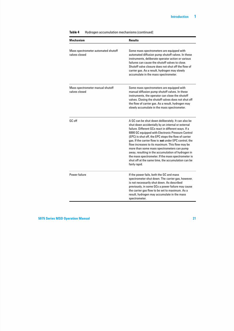
Mass spectrometer automated shutoff
valves closed
Some mass spectrometers are equipped with
automated diffusion pump shutoff valves. In these
instruments, deliberate operator action or various
failures can cause the shutoff valves to close.
Shutoff valve closure does not shut off the flow of
carrier gas. As a result, hydrogen may slowlyaccumulate in the mass spectrometer.
Mass spectrometer manual shutoff
valves closed
Some mass spectrometers are equipped with
manual diffusion pump shutoff valves. In these
instruments, the operator can close the shutoff
valves. Closing the shutoff valves does not shut off
the flow of carrier gas. As a result, hydrogen mayslowly accumulate in the mass spectrometer.
GC off A GC can be shut down deliberately. It can also be
shut down accidentally by an internal or external
failure. Different GCs react in different ways. If a
6890 GC equipped with Electronic Pressure Control
(EPC) is shut off, the EPC stops the flow of carriergas. If the carrier flow is not under EPC control, the
flow increases to its maximum. This flow may be
more than some mass spectrometers can pump
away, resulting in the accumulation of hydrogen in
the mass spectrometer. If the mass spectrometer is
shut off at the same time, the accumulation can be
fairly rapid.
Power failure If the power fails, both the GC and mass
spectrometer shut down. The carrier gas, however,
is not necessarily shut down. As described
previously, in some GCs a power failure may cause
the carrier gas flow to be set to maximum. As a
result, hydrogen may accumulate in the mass
spectrometer.
Table 4 Hydrogen accumulation mechanisms (continued)
Mechanism Results
7/14/2019 Agilent 5973 MS User Manual
http://slidepdf.com/reader/full/agilent-5973-ms-user-manual 22/162
22 5975 Series MSD Operation Manual
1 Introduction
Precautions
Take the following precautions when operating a GC/MSD system with
hydrogen carrier gas.
Equipment precaution
You MUST make sure the front side-plate thumbscrew is fastened finger-tight.
Do not overtighten the thumbscrew; it can cause air leaks.
You must remove the plastic cover over the glass window on the front of a 5975
MSD. In the unlikely event of an explosion, this cover may dislodge.
General laboratory precautions
• Avoid leaks in the carrier gas lines. Use leak-checking equipment toperiodically check for hydrogen leaks.
• Eliminate from your laboratory as many ignition sources as possible (open
flames, devices that can spark, sources of static electricity, etc.).
• Do not allow hydrogen from a high pressure cylinder to vent directly to
atmosphere (danger of self-ignition).
• Use a hydrogen generator instead of bottled hydrogen.
WARNING Once hydrogen has accumulated in a mass spectrometer, extreme caution must beused when removing it. Incorrect startup of a mass spectrometer filled with
hydrogen can cause an explosion.
WARNINGAfter a power failure, the mass spectrometer may start up and begin the pumpdown
process by itself. This does not guarantee that all hydrogen has been removed from
the system or that the explosion hazard has been removed.
WARNINGFailure to secure your MSD as described above greatly increases the chance of
personal injury in the event of an explosion.
7/14/2019 Agilent 5973 MS User Manual
http://slidepdf.com/reader/full/agilent-5973-ms-user-manual 23/162
Introduction 1
5975 Series MSD Operation Manual 23
Operating precautions
• Turn off the hydrogen at its source every time you shut down the GC or
MSD.
• Turn off the hydrogen at its source every time you vent the MSD (do not
heat the capillary column without carrier gas f low).
• Turn off the hydrogen at its source every time shutoff valves in an MSD are
closed (do not heat the capillary column without carrier gas flow).
• Turn off the hydrogen at its source if a power failure occurs.• If a power failure occurs while the GC/MSD system is unattended, even if
the system has restarted by itself:
1 Immediately turn off the hydrogen at its source.
2 Turn off the GC.
3 Turn off the MSD and allow it to cool for 1 hour.
4 Eliminate all potential sources of ignition in the room.5 Open the vacuum manifold of the MSD to atmosphere.
6 Wait at least 10 minutes to allow any hydrogen to dissipate.
7 Start up the GC and MSD as normal.
When using hydrogen gascheck the system for leaks to prevent possible fire
and explosion hazards based on local Environmental Health and Safety (EHS)
requirements. Always check for leaks after changing a tank or servicing the
gas lines. Always make sure the vent line is vented into a fume hood.
7/14/2019 Agilent 5973 MS User Manual
http://slidepdf.com/reader/full/agilent-5973-ms-user-manual 24/162
24 5975 Series MSD Operation Manual
1 Introduction
Safety and Regulatory Certifications
The 5975 Series MSD conforms to the following safety standards:
• Canadian Standards Association (CSA): CAN/CSA-C222 No. 61010-1-04
• CSA/Nationally Recognized Test Laboratory (NRTL): UL 61010–1
• International Electrotechnical Commission (IEC): 61010–1
• EuroNorm (EN): 61010–1
The 5975 MSD conforms to the following regulations on Electromagnetic
Compatibility (EMC) and Radio Frequency Interference (RFI):
• CISPR 11/EN 55011: Group 1, Class A
• IEC/EN 61326
• AUS/NZ
This ISM device complies with Canadian ICES-001. Cet appareil ISM est conforme a la norme NMB—001 du Canada.
The 5975 Series MSD is designed and manufactured under a quality system
registered to ISO 9001.
Information
The Agilent Technologies 5975 Series MSD meets the following IEC
(International Electro-technical Commission) classifications: Equipment Class
I, Laboratory Equipment, Installation Category II, Pollution Degree 2.
This unit has been designed and tested in accordance with recognized safety
standards and is designed for use indoors. If the instrument is used in a
manner not specified by the manufacturer, the protection provided by theinstrument may be impaired. Whenever the safety protection of the MSD has
been compromised, disconnect the unit from all power sources and secure the
unit against unintended operation.
Refer servicing to qualified service personnel. Substituting parts or
performing any unauthorized modification to the instrument may result in a
safety hazard.

7/14/2019 Agilent 5973 MS User Manual
http://slidepdf.com/reader/full/agilent-5973-ms-user-manual 25/162
Introduction 1
5975 Series MSD Operation Manual 25
Symbols
Warnings in the manual or on the instrument must be observed during all
phases of operation, service, and repair of this instrument. Failure to comply
with these precautions violates safety standards of design and the intended
use of the instrument. Agilent Technologies assumes no liability for the
customer’s failure to comply with these requirements.
See accompanying instructions for more information.
Indicates a hot surface.
Indicates hazardous voltages.
Indicates earth (ground) terminal.
Indicates potential explosion hazard.
Indicates radioactivity hazard.
Indicates electrostatic discharge hazard.
Indicates that you must not discard this
electrical/electronic product in domestic household
waste.
or

7/14/2019 Agilent 5973 MS User Manual
http://slidepdf.com/reader/full/agilent-5973-ms-user-manual 26/162
26 5975 Series MSD Operation Manual
1 Introduction
Electromagnetic compatibility
This device complies with the requirements of CISPR 11. Operation is subject
to the following two conditions:
• This device may not cause harmful interference.
• This device must accept any interference received, including interference
that may cause undesired operation.
If this equipment does cause harmful interference to radio or television
reception, which can be determined by turning the equipment off and on, theuser is encouraged to try one or more of the following measures:
1 Relocate the radio or antenna.
2 Move the device away from the radio or television.
3 Plug the device into a different electrical outlet, so that the device and the
radio or television are on separate electrical circuits.
4 Make sure that all peripheral devices are also certified.5 Make sure that appropriate cables are used to connect the device to
peripheral equipment.
6 Consult your equipment dealer, Agilent Technologies, or an experienced
technician for assistance.
7 Changes or modifications not expressly approved by Agilent Technologies
could void the user’s authority to operate the equipment.
Sound emission declaration
Sound pressure
Sound pressure Lp <70 dB according to EN 27779:1991.
Schalldruckpegel
Schalldruckpegel LP <70 dB am nach EN 27779:1991.
7/14/2019 Agilent 5973 MS User Manual
http://slidepdf.com/reader/full/agilent-5973-ms-user-manual 27/162
Introduction 1
5975 Series MSD Operation Manual 27
Cleaning/Recycling the Product
To clean the unit, disconnect the power and wipe down with a damp, lint-free
cloth. For recycling, contact your local Agilent sales office.
Liquid Spillage
Do not spill liquids on the MSD.
Moving or Storing the MSD
The best way to keep your MSD functioning properly is to keep it pumped
down and hot, with carrier gas flow. If you plan to move or store your MSD, a
few additional precautions are required. The MSD must remain upright at all
times; this requires special caution when moving. The MSD should not be left
vented to atmosphere for long periods.
1

7/14/2019 Agilent 5973 MS User Manual
http://slidepdf.com/reader/full/agilent-5973-ms-user-manual 28/162
28 5975 Series MSD Operation Manual
1 Introduction
A il t 5975 S i MSD
7/14/2019 Agilent 5973 MS User Manual
http://slidepdf.com/reader/full/agilent-5973-ms-user-manual 29/162
29
Agilent 5975 Series MSD
Operation Manual
Agilent Technologies
2
Installing GC Columns
Columns 30
Conditioning columns 30
Conditioning ferrules 31Tips and hints 31
To reconfigure a 6850 GC column on its basket 32
To prepare a capillary column for installation 37
To install a capillary column in a split/splitless inlet 39
To condition a capillary column 41
To install a capillary column in the GC/MSD interface 43
Before you can operate your GC/MSD system, you must select, install, and
condition a GC column. This chapter will show you how to install and
condition a column. For correct column and flow selection, you must know
what type of vacuum system your MSD has. The serial number tag on the lower
front of the left side panel shows the model number.
2 Installing GC Columns
7/14/2019 Agilent 5973 MS User Manual
http://slidepdf.com/reader/full/agilent-5973-ms-user-manual 30/162
30 5975 Series MSD Operation Manual
2 Installing GC Columns
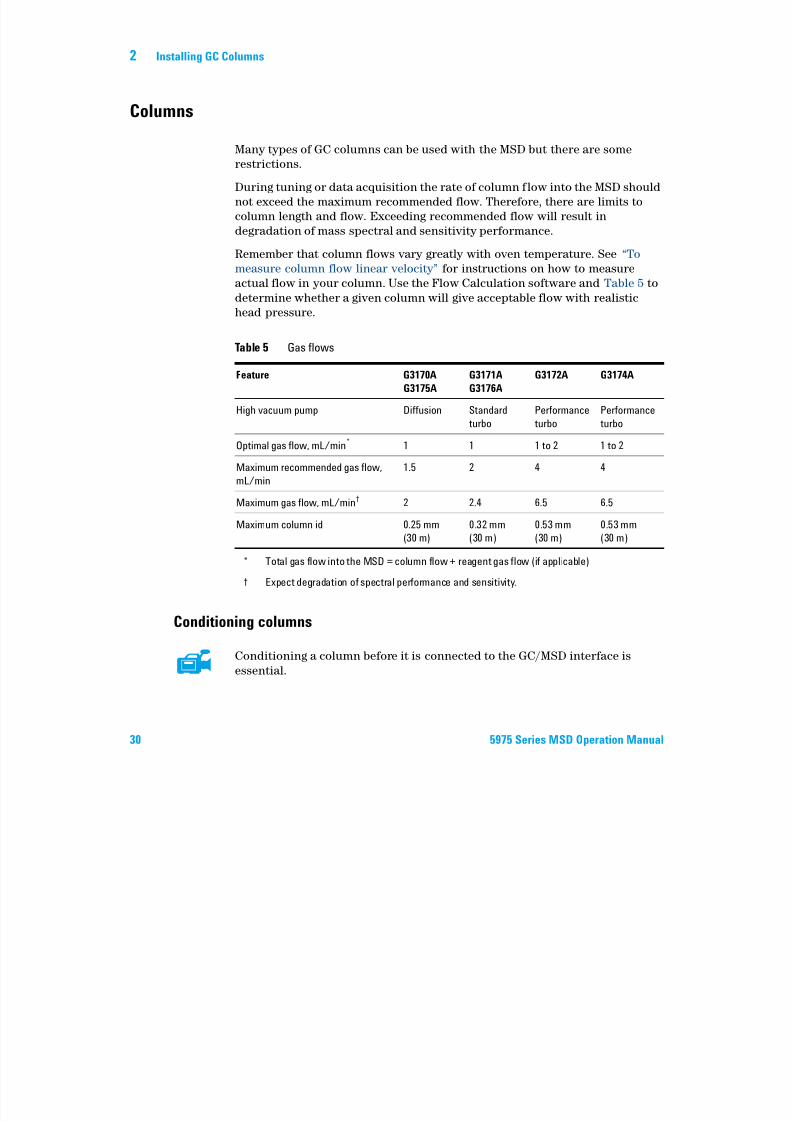
Columns
Many types of GC columns can be used with the MSD but there are some
restrictions.
During tuning or data acquisition the rate of column flow into the MSD should
not exceed the maximum recommended flow. Therefore, there are limits to
column length and flow. Exceeding recommended flow will result in
degradation of mass spectral and sensitivity performance.
Remember that column flows vary greatly with oven temperature. See “To
measure column flow linear velocity” for instructions on how to measure
actual flow in your column. Use the Flow Calculation software and Table 5 to
determine whether a given column will give acceptable flow with realistic
head pressure.
Conditioning columns
Conditioning a column before it is connected to the GC/MSD interface is
essential.
Table 5 Gas flows
Feature G3170A
G3175A
G3171A
G3176A
G3172A G3174A
High vacuum pump Diffusion Standard
turbo
Performance
turbo
Performance
turbo
Optimal gas flow, mL/min*
* Total gas flow into the MSD = column flow + reagent gas flow (if applicable)
1 1 1 to 2 1 to 2
Maximum recommended gas flow,mL/min
1.5 2 4 4
Maximum gas flow, mL/min†
† Expect degradation of spectral performance and sensitivity.
2 2.4 6.5 6.5
Maximum column id 0.25 mm
(30 m)
0.32 mm
(30 m)
0.53 mm
(30 m)
0.53 mm
(30 m)
Installing GC Columns 2
7/14/2019 Agilent 5973 MS User Manual
http://slidepdf.com/reader/full/agilent-5973-ms-user-manual 31/162
Installing GC Columns 2
5975 Series MSD Operation Manual 31
A small portion of the capillary column stationary phase is often carried away
by the carrier gas. This is called column bleed. Column bleed deposits traces of the stationary phase in the MSD ion source. This decreases MSD sensitivity
and makes cleaning the ion source necessary.
Column bleed is most common in new or poorly crosslinked columns. It is
much worse if there are traces of oxygen in the carrier gas when the column is
heated. To minimize column bleed, all capillary columns should be
conditioned before they are installed in the GC/MSD interface.
Conditioning ferrules
Heating ferrules to their maximum expected operating temperature a few
times before they are installed can reduce chemical bleed from the ferrules.
Tips and hints
• The column installation procedures for the 5975 Series MSDs is different from that for previous MSDs. Using the procedure from another instrument
may not work and may damage the column or the MSD.
• You can remove old ferrules from column nuts with an ordinary push pin.
• Always use carrier gas that is at least 99.9995% pure.
• Because of thermal expansion, new ferrules may loosen after heating and
cooling a few times. Check for tightness after two or three heating cycles.
• Always wear clean gloves when handling columns, especially the end that
will be inserted into the GC/MSD interface.
WARNINGIf you are using hydrogen as a carrier gas, do not start carrier gas flow until the
column is installed in the MSD and the MSD has been pumped down. If the vacuum
pumps are off, hydrogen will accumulate in the MSD and an explosion may occur.
See “Hydrogen Safety” .
WARNINGAlways wear safety glasses when handling capillary columns. Use care to avoid
puncturing your skin with the end of the column.
2 Installing GC Columns
7/14/2019 Agilent 5973 MS User Manual
http://slidepdf.com/reader/full/agilent-5973-ms-user-manual 32/162
32 5975 Series MSD Operation Manual
2 Installing GC Columns
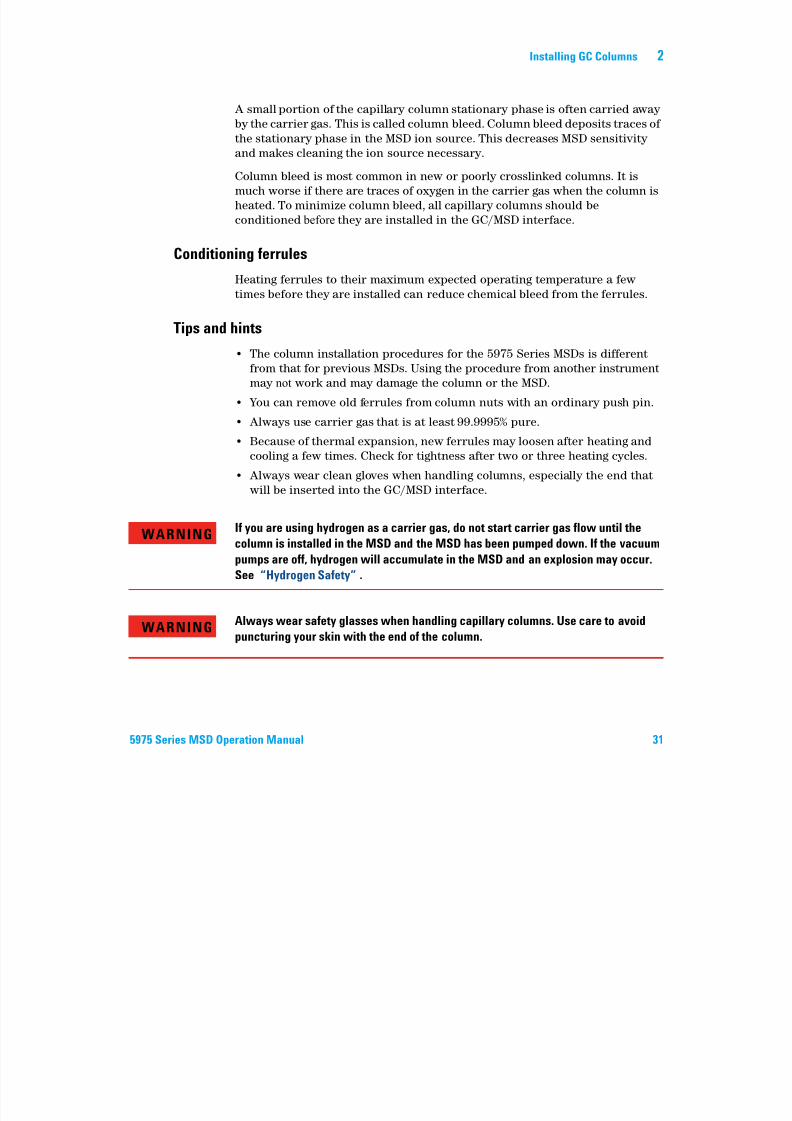
To reconfigure a 6850 GC column on its basket
Before installing a 6850, first reconfigure it to better position the column ends
for installation in the GC MSD interface.
1 Lay the column (19091S-433E found in the GC ship kit) on a clean surface
with the column label facing the user in the 12 o’clock position. Note that
the inlet and outlet ends of the column are oriented the same as when a GC
detector is used and the column outlet is positioned at the back (closer to
the fan) of the column cage holder. See Figure 2.
Figure 2 Column
Column inlet
Column outlet
6850 column nut
Installing GC Columns 2
7/14/2019 Agilent 5973 MS User Manual
http://slidepdf.com/reader/full/agilent-5973-ms-user-manual 33/162
g
5975 Series MSD Operation Manual 33
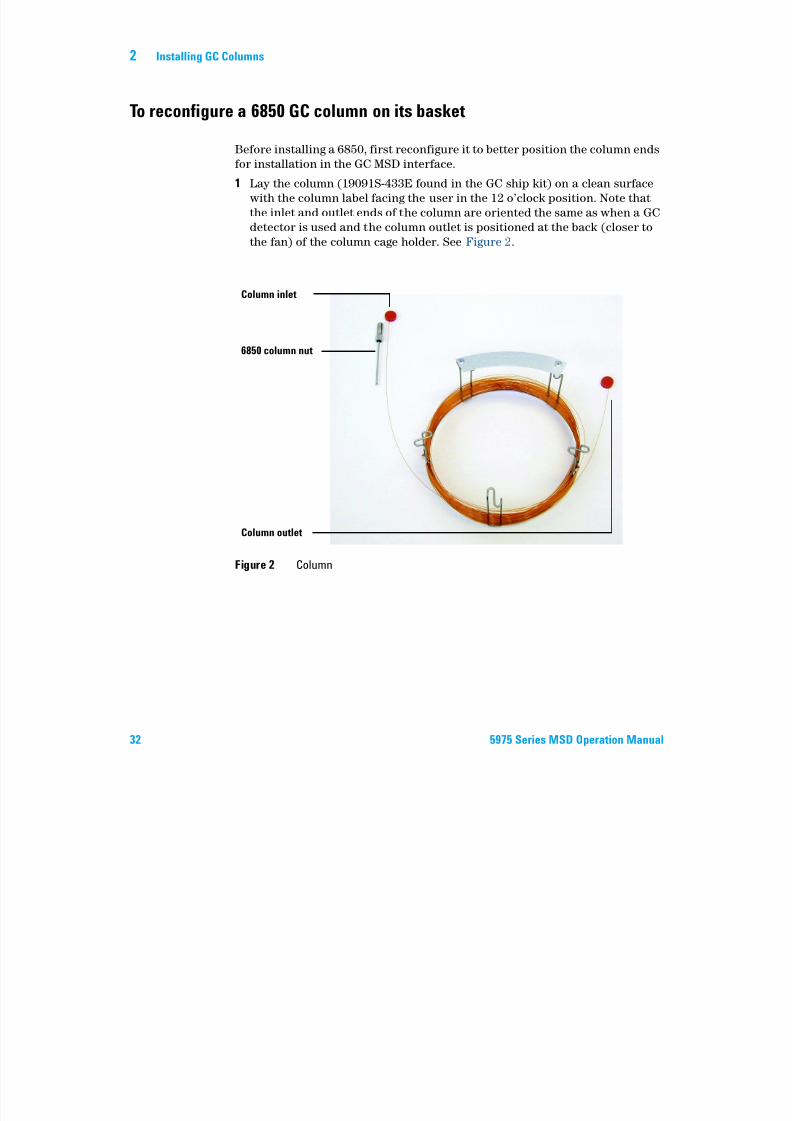
2 Remove the septum cap from the column OUTLET side and uncoil 2 column
loops. See Figure 3.
3 Attach three column clips (part number G2630-20890) to the column cage
as follows:• Attach one clip onto the back of the 1 o’clock cross-member piece of the
column cage.
• Attach two clips onto the front of the 3 o’clock cross-member piece of the
column cage.
These clips will help provide appropriate orientation of column ends for
their insertion into the GC inlet and MSD interface.
Figure 3 Column with 2 uncoiled loops
1 o’clock cross-member
3 o’clock cross-member
2 Installing GC Columns
7/14/2019 Agilent 5973 MS User Manual
http://slidepdf.com/reader/full/agilent-5973-ms-user-manual 34/162
34 5975 Series MSD Operation Manual
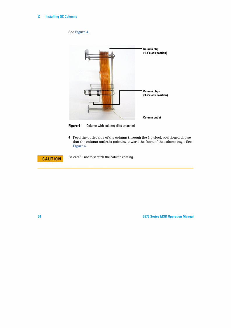
See Figure 4.
4 Feed the outlet side of the column through the 1 o’clock positioned clip sothat the column outlet is pointing toward the front of the column cage. See
Figure 5.
Figure 4 Column with column clips attached
Column clip
(1 o’clock postion)
Column clips
(3 o’clock position)
Column outlet
CAUTIONBe careful not to scratch the column coating.
Installing GC Columns 2
7/14/2019 Agilent 5973 MS User Manual
http://slidepdf.com/reader/full/agilent-5973-ms-user-manual 35/162
5975 Series MSD Operation Manual 35
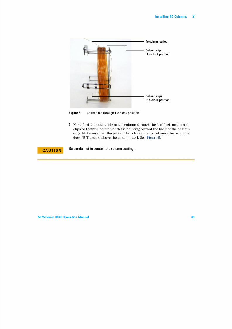
5 Next, feed the outlet side of the column through the 3 o’clock positioned
clips so that the column outlet is pointing toward the back of the column
cage. Make sure that the part of the column that is between the two clips
does NOT extend above the column label. See Figure 6.
Figure 5 Column fed through 1 o’clock position
To column outlet
Column clip
(1 o’clock position)
Column clips
(3 o’clock position)
CAUTIONBe careful not to scratch the column coating.
2 Installing GC Columns
7/14/2019 Agilent 5973 MS User Manual
http://slidepdf.com/reader/full/agilent-5973-ms-user-manual 36/162
36 5975 Series MSD Operation Manual
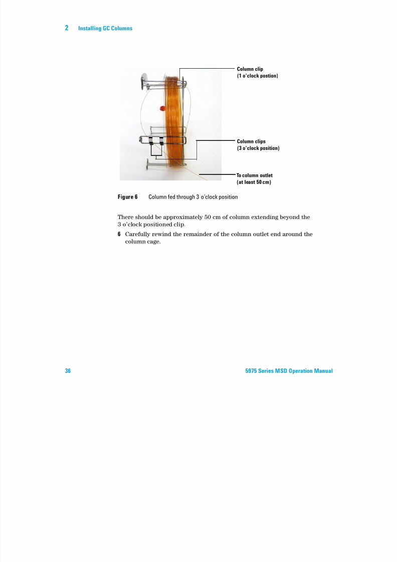
There should be approximately 50 cm of column extending beyond the
3 o’clock positioned clip.
6 Carefully rewind the remainder of the column outlet end around thecolumn cage.
Figure 6 Column fed through 3 o’clock position
Column clip
(1 o’clock postion)
Column clips
(3 o’clock position)
To column outlet
(at least 50 cm)
Installing GC Columns 2
7/14/2019 Agilent 5973 MS User Manual
http://slidepdf.com/reader/full/agilent-5973-ms-user-manual 37/162
5975 Series MSD Operation Manual 37
To prepare a capillary column for installation
Materials needed
• Capillary column
• Column cutter, ceramic (5181-8836) or diamond (5183-4620)
• Ferrules
• 0.27-mm id, for 0.10-mm id columns (5062-3518)
• 0.37-mm id, for 0.20-mm id columns (5062-3516)
• 0.40-mm id, for 0.25-mm id columns (5181-3323)
• 0.5-mm id, for 0.32-mm id columns (5062-3514)
• 0.8-mm id, for 0.53-mm id columns (5062-3512)
• Gloves, clean
• Large (8650-0030)
• Small (8650-0029)
• Inlet column nut (5181-8830 for Agilent 7890A, 7820A and 6890, or
5183-4732 for 6850)
• Magnifying loupe
• Septum (may be old, used inlet septum)
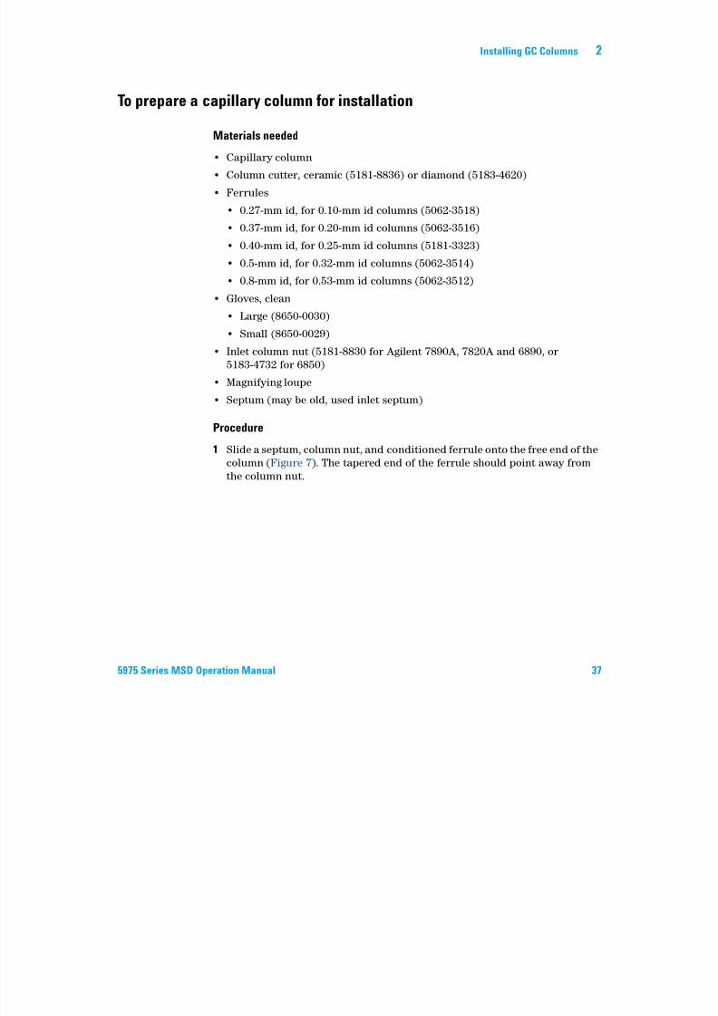
Procedure
1 Slide a septum, column nut, and conditioned ferrule onto the free end of the
column (Figure 7). The tapered end of the ferrule should point away from
the column nut.
2 Installing GC Columns
7/14/2019 Agilent 5973 MS User Manual
http://slidepdf.com/reader/full/agilent-5973-ms-user-manual 38/162
38 5975 Series MSD Operation Manual
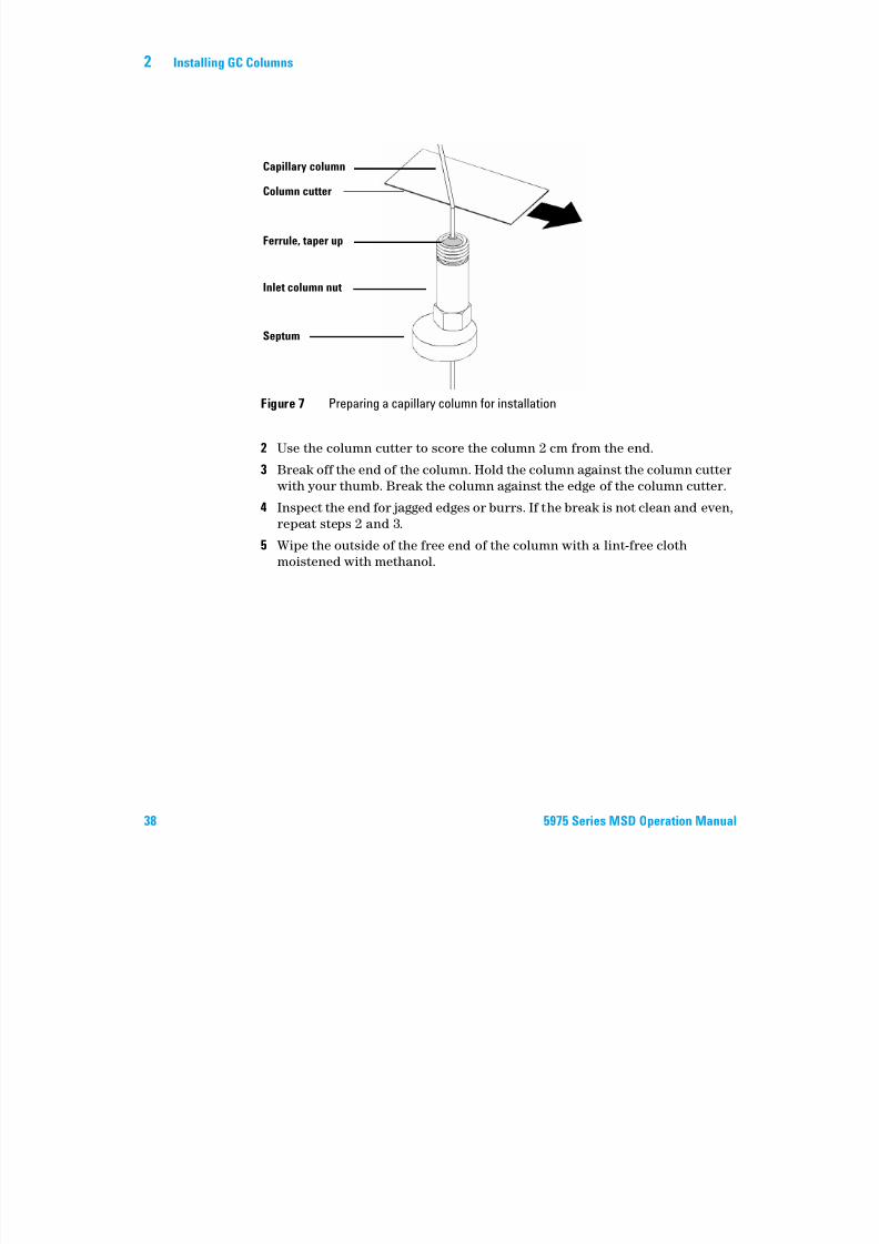
2 Use the column cutter to score the column 2 cm from the end.
3 Break off the end of the column. Hold the column against the column cutter
with your thumb. Break the column against the edge of the column cutter.
4 Inspect the end for jagged edges or burrs. If the break is not clean and even,
repeat steps 2 and 3.5 Wipe the outside of the free end of the column with a lint-free cloth
moistened with methanol.
Figure 7 Preparing a capillary column for installation
Capillary column
Column cutter
Ferrule, taper up
Inlet column nut
Septum
Installing GC Columns 2
7/14/2019 Agilent 5973 MS User Manual
http://slidepdf.com/reader/full/agilent-5973-ms-user-manual 39/162
5975 Series MSD Operation Manual 39
To install a capillary column in a split/splitless inlet
Materials needed
• Gloves, clean
• Large (8650-0030)
• Small (8650-0029)
• Metric ruler
• Wrench, open-end, 1/4-inch and 5/16-inch (8710-0510)
To install columns in other types of inlets, refer to your Gas Chromatograph
User Information.
Procedure
1 Prepare the column for installation ( “To prepare a capillary column for
installation” on page 37).
2 Position the column so it extends 4 to 6 mm past the end of the ferrule
(Figure 8).
Figure 8 Installing a capillary column for a split/splitless inlet
Insulation cup
Reducing nut
Capillary column
Ferrule (inside nut)
Inlet column nut
Septum
4 to 6 mm
2 Installing GC Columns
7/14/2019 Agilent 5973 MS User Manual
http://slidepdf.com/reader/full/agilent-5973-ms-user-manual 40/162
40 5975 Series MSD Operation Manual
3 Slide the septum to place the nut and ferrule in the correct position.
4 Insert the column in the inlet.
5 Slide the nut up the column to the inlet base and finger-tighten the nut.
6 Adjust the column position so the septum is even with the bottom of the
column nut.
7 Tighten the column nut an additional 1/4 to 1/2 turn. The column should
not slide with a gentle tug.
8 Start carrier gas flow.9 Verify flow by submerging the free end of the column in isopropanol. Look
for bubbles.
Installing GC Columns 2

7/14/2019 Agilent 5973 MS User Manual
http://slidepdf.com/reader/full/agilent-5973-ms-user-manual 41/162
5975 Series MSD Operation Manual 41
To condition a capillary column
Materials needed
• Carrier gas, (99.9995% pure or better)
• Wrench, open-end, 1/4-inch and 5/16-inch (8710-0510)
Procedure
1 Install the column in the GC inlet ( “To install a capillary column in asplit/splitless inlet” on page 39).
2 Allow the carrier gas to flow through the column for 5 minutes without
heating the GC oven.
3 Ramp the oven temperature at 5 °C/minute to 10 °C above your highest
analytical temperature.
4 Once the oven temperature exceeds 80 °C, inject 5 µL methanol into the GC.
Repeat two more times at 5-minute intervals. This helps remove any contamination from the column before it is installed into the GC/MSD
interface.
5 Hold this temperature. Allow the carrier gas to flow for several hours.
6 Return the GC oven temperature to a low standby temperature.
WARNING
Do not condition your capillary column with hydrogen. Hydrogen accumulation in
the GC oven can result in an explosion. If you plan to use hydrogen as your carrier
gas, first condition the column with ultrapure (99.999% or better) inert gas such as
helium, nitrogen, or argon.
CAUTIONNever exceed the maximum column temperature, either in the GC/MSD interface, the
GC oven, or the inlet.
2 Installing GC Columns
7/14/2019 Agilent 5973 MS User Manual
http://slidepdf.com/reader/full/agilent-5973-ms-user-manual 42/162
42 5975 Series MSD Operation Manual
See also
For more information about installing a capillary column, refer to the
application note Optimizing Splitless Injections on Your GC for High
Performance MS Analysis, publication number 5988-9944EN.
Installing GC Columns 2
7/14/2019 Agilent 5973 MS User Manual
http://slidepdf.com/reader/full/agilent-5973-ms-user-manual 43/162
5975 Series MSD Operation Manual 43
To install a capillary column in the GC/MSD interface
Agilent 7890A and 7820A, and 6890 GCs
Materials needed
• Column cutter, ceramic (5181-8836) or diamond (5183-4620)
• Ferrules
• 0.3-mm id, for 0.10-mm id columns (5062-3507)
• 0.4-mm id, for 0.20- and 0.25-mm id columns (5062-3508)
• 0.5-mm id, for 0.32-mm id columns (5062-3506)
• 0.8-mm id, for 0.53-mm id columns (5062-3512)
• Flashlight
• Hand lens (magnifying loupe)
• Gloves, clean
• Large (8650-0030)
• Small (8650-0029)
• Interface column nut (05988-20066)
• Safety glasses
• Wrench, open-end, 1/4-inch and 5/16-inch (8710-0510)
Procedure
1 Condition the column (page 41).
2 Vent the MSD (page 82) and open the analyzer chamber (page 84). Be sure
you can see the end of the GC/MSD interface.
3 If the CI interface is installed, remove the spring-loaded tip seal from the
MSD end of the interface.
4 Slide an interface nut and conditioned ferrule onto the free end of the GC
column. The tapered end of the ferrule must point towards the nut.
CAUTIONNote that the column installation procedure for the 5975 Series MSDs is different from
that for most previous MSDs. Using the procedure from another instrument may result
in poor sensitivity and possible damage to the MSD.
2 Installing GC Columns
7/14/2019 Agilent 5973 MS User Manual
http://slidepdf.com/reader/full/agilent-5973-ms-user-manual 44/162
44 5975 Series MSD Operation Manual
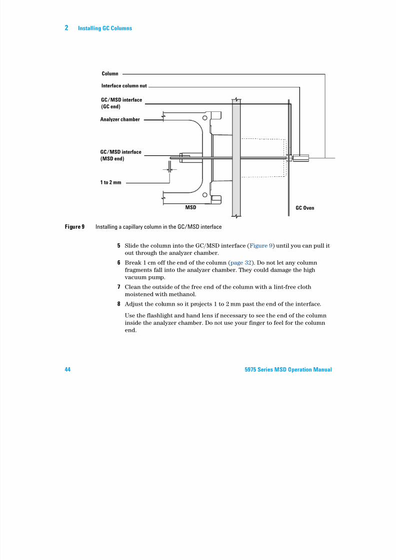
5 Slide the column into the GC/MSD interface (Figure 9) until you can pull it
out through the analyzer chamber.
6 Break 1 cm off the end of the column (page 32). Do not let any column
fragments fall into the analyzer chamber. They could damage the high
vacuum pump.
7 Clean the outside of the free end of the column with a lint-free cloth
moistened with methanol.8 Adjust the column so it projects 1 to 2 mm past the end of the interface.
Use the flashlight and hand lens if necessary to see the end of the column
inside the analyzer chamber. Do not use your finger to feel for the column
end.
Figure 9 Installing a capillary column in the GC/MSD interface
1 to 2 mm
GC/MSD interface
(MSD end)
Analyzer chamber
GC/MSD interface
(GC end)
Interface column nut
Column
MSD GC Oven
Installing GC Columns 2
7/14/2019 Agilent 5973 MS User Manual
http://slidepdf.com/reader/full/agilent-5973-ms-user-manual 45/162
5975 Series MSD Operation Manual 45
9 Hand-tighten the nut. Make sure the position of the column does not change
as you tighten the nut. Reinstall the spring-loaded tip seal if it was removedearlier.
10 Check the GC oven to be sure that the column does not touch the oven
walls.
11 Tighten the nut 1/4 to 1/2 turn. Check the tightness after one or two heat
cycles.
6850 GC1 Carefully unwind the outlet end of the GC column until the
3 o’clock clip is reached.
2 Slide an interface column nut (part number 05988-20066) and ferrule (part
number 5062-3508) onto the outlet end of the GC column.
The tapered end of the ferrule must point towards the nut.
3 Slide the column into the GC/MSD interface until the column protrudesinto the analyzer chamber at least 5 cm.
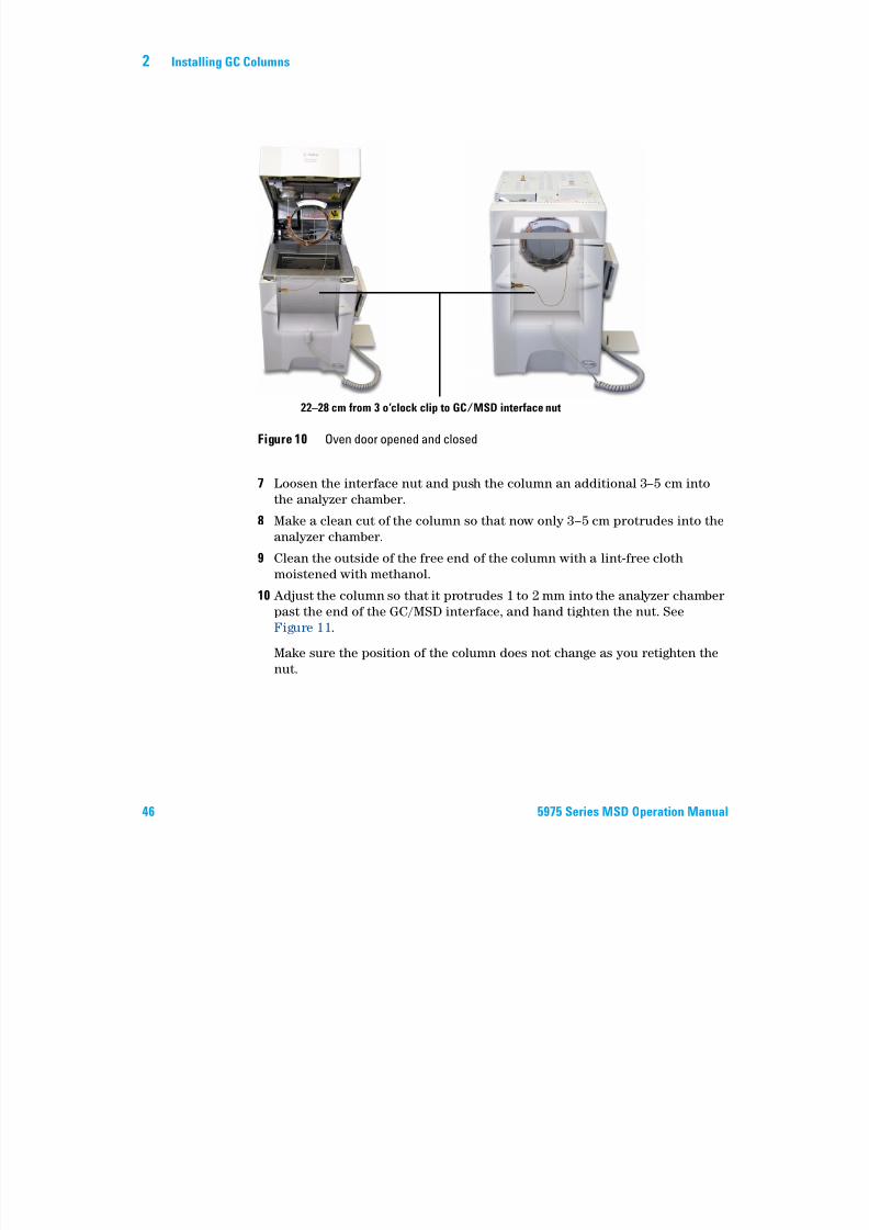
4 Adjust the length of the column from the 3 o’clock clip to the back of the
interface column nut to be 22–28 cm. See Figure 10.
5 Hand tighten the interface nut.
6 Carefully close the oven door while observing to see that the column does
not develop sharp bends or touch the oven walls/floor. Try this procedure
several times.
2 Installing GC Columns
7/14/2019 Agilent 5973 MS User Manual
http://slidepdf.com/reader/full/agilent-5973-ms-user-manual 46/162
46 5975 Series MSD Operation Manual
7 Loosen the interface nut and push the column an additional 3–5 cm into
the analyzer chamber.
8 Make a clean cut of the column so that now only 3–5 cm protrudes into theanalyzer chamber.
9 Clean the outside of the free end of the column with a lint-free cloth
moistened with methanol.
10 Adjust the column so that it protrudes 1 to 2 mm into the analyzer chamber
past the end of the GC/MSD interface, and hand tighten the nut. See
Figure 11.
Make sure the position of the column does not change as you retighten the
nut.
Figure 10 Oven door opened and closed
22–28 cm from 3 o’clock clip to GC/MSD interface nut
Installing GC Columns 2
7/14/2019 Agilent 5973 MS User Manual
http://slidepdf.com/reader/full/agilent-5973-ms-user-manual 47/162
5975 Series MSD Operation Manual 47
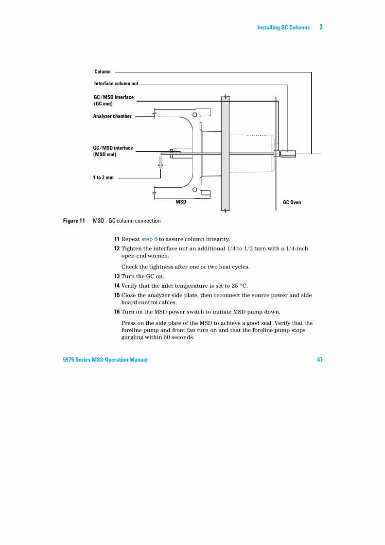
11 Repeat step 6 to assure column integrity.
12 Tighten the interface nut an additional 1/4 to 1/2 turn with a 1/4-inch
open-end wrench.
Check the tightness after one or two heat cycles.
13 Turn the GC on.
14 Verify that the inlet temperature is set to 25 °C.15 Close the analyzer side plate, then reconnect the source power and side
board control cables.
16 Turn on the MSD power switch to initiate MSD pump down.
Press on the side plate of the MSD to achieve a good seal. Verify that the
foreline pump and front fan turn on and that the foreline pump stops
gurgling within 60 seconds.
Figure 11 MSD - GC column connection
1 to 2 mm
GC/MSD interface
(MSD end)
Analyzer chamber
GC/MSD interface
(GC end)
Interface column nut
Column
MSD GC Oven
2 Installing GC Columns

7/14/2019 Agilent 5973 MS User Manual
http://slidepdf.com/reader/full/agilent-5973-ms-user-manual 48/162
48 5975 Series MSD Operation Manual
17 Reinstall the MSD analyzer cover.
Agilent 5975 Series MSD
Operation Manual
7/14/2019 Agilent 5973 MS User Manual
http://slidepdf.com/reader/full/agilent-5973-ms-user-manual 49/162
49Agilent Technologies
3Operating in Electron Impact (EI) Mode
Operating the MSD from the Data System 51
Operating the MSD from the LCP 51
LCP Status Messages 53
LCP Menus 55
The EI GC/MSD Interface 58
Before You Turn On the MSD 60
Pumping Down 61
Controlling Temperatures 61
Controlling Column Flow 62
Venting the MSD 63
To view MSD analyzer temperature and vacuum status 64
To set monitors for MSD temperature and vacuum status 66
To set the MSD analyzer temperatures 67
To set the GC/MSD interface temperature from the ChemStation 69
To monitor high vacuum pressure 71
To measure column flow linear velocity 73
To confirm column flow 74To tune the MSD 75
To verify system performance 76
High-Mass Testing (5975 Series MSDs) 77
To remove the MSD covers 80
To vent the MSD 82
To open the analyzer chamber 84
To close the analyzer chamber 87To pump down the MSD 91
To move or store the MSD 93
To set the interface temperature from the GC 95
3 Operating in Electron Impact (EI) Mode
7/14/2019 Agilent 5973 MS User Manual
http://slidepdf.com/reader/full/agilent-5973-ms-user-manual 50/162
50 5975 Series MSD Operation Manual
How to perform some basic operating procedures for the MSD.
CAUTIONThe software and firmware are revised periodically. If the steps in these procedures do
not match your MSD ChemStation software, refer to the manuals and online help
supplied with the software for more information.
Operating in Electron Impact (EI) Mode 3
7/14/2019 Agilent 5973 MS User Manual
http://slidepdf.com/reader/full/agilent-5973-ms-user-manual 51/162
5975 Series MSD Operation Manual 51
Operating the MSD from the Data System
The software performs tasks such as pumping down, monitoring pressures,
setting temperatures, tuning, and preparing to vent. These tasks are described
in this chapter. Data acquisition and data analysis are described in the
manuals and online help supplied with the MSD ChemStation software.
Operating the MSD from the LCP
The local control panel (LCP) shows the status of the MSD or initiates a task
on the MSD without using the Agilent GC/MSD ChemStation.
The GC/MSD ChemStation may be located anywhere on the site local area
network (LAN), so the GC/MSD ChemStation might not be near the
instrument itself. And because the LCP communicates with the GC/MSD
ChemStation via the LAN, you can access GC/MSD ChemStation software
functions, such as tuning and starting a run, right from the MSD.
Modes of operation
The LCP has two modes of operation: Status and Menu.
Status mode requires no interaction and simply displays the current status of
the MSD instrument or its various communication connections. If you select
[Menu], then [No/Cancel], you will be returned to the Status mode.
Menu mode allows you to query various aspects of the GC/MSD and to initiate
some actions like running a method or sequence or preparing to vent the
system.
To access a particular menu option:
NOTEOnly certain functions are available from the LCP; the GC/MSD ChemStation is the
full-featured controller for most instrument control operations.
Press [Menu] until the desired menu appears.
Press [Item] until the desired menu item appears.
3 Operating in Electron Impact (EI) Mode

7/14/2019 Agilent 5973 MS User Manual
http://slidepdf.com/reader/full/agilent-5973-ms-user-manual 52/162
52 5975 Series MSD Operation Manual
Use one or more of the following keys as appropriate to respond to prompts or
select options:
After you make your selection, or if you cycle through all available menus, the
display automatically returns to Status mode.
Pressing [Menu], then [No/Cancel], will always display the Status mode.
Pressing [No/Cancel] twice will always return to the Status mode.
Use [Up] to increase the displayed value or to scroll up (such as in a message list).
Use [Down] to decrease the displayed value or to scroll down (such as in a message
list).
Use [Yes/Select] to accept the current value.
Use [No/Cancel] to return to the Status mode.
Operating in Electron Impact (EI) Mode 3

7/14/2019 Agilent 5973 MS User Manual
http://slidepdf.com/reader/full/agilent-5973-ms-user-manual 53/162
5975 Series MSD Operation Manual 53
LCP Status Messages
The following messages may be displayed on the LCP to inform you of the
status of the MSD system. If the LCP is currently in Menu mode, cycle through
the menus to return to Status mode.
ChemStation Loading <timestamp>
The Agilent MSD Productivity ChemStation software is starting up.
Executing <type>tune
A tuning procedure is in progress (type = QuickTune or Autotune).
Instrument Available <timestamp>
The Agilent MSD Productivity ChemStation software is not running.
Loading Method <method name>
Method parameters are being sent to the MSD.
Loading MSD FirmwareThe MSD’s firmware is being initialized.
The following messages alternately appear on the LCP if the MSD does NOT
complete its bootup sequence properly:
Server not Found
Check LAN Connection
Seeking Server
Bootp Query xxx
These messages indicate that the MSD has not received its unique IP address
from the Agilent Bootp Service. If the messages persist after you have logged
onto your account on the GC/MSD ChemStation, consult the Troubleshooting
section of the Software Installation manual.
NOTENo messages will be displayed if an online instrument session is not currently running on
the GC/MSD ChemStation.
3 Operating in Electron Impact (EI) Mode
7/14/2019 Agilent 5973 MS User Manual
http://slidepdf.com/reader/full/agilent-5973-ms-user-manual 54/162
54 5975 Series MSD Operation Manual
Loading OS
The operating system of the instrument controller is being initialized.
<method> Complete <timestamp>
The run and subsequent data processing are done. The same message appears
even if the run was terminated prematurely.
Method Loaded <method name>Method parameters were sent to the MSD.
MS locked by <computer name>
MS parameters can only be changed from the GC/MSD ChemStation.
Press Sideplate
A reminder during startup to press the MSD sideplate to ensure an adequate
vacuum seal.
Run: <method> Acquiring <datafile>
A run is in progress; data is being acquired to the designated data file.
To view system status during startup
1 The following messages are displayed on the LCP display during startup:
• Press sideplate
• Loading OS
• Press sideplate
• Loading MSD Firmware
2 Continue to press the sideplate of the MSD until the MSD Ready message
appears. This helps the instrument to pump down more quickly.
Operating in Electron Impact (EI) Mode 3
LCP M
7/14/2019 Agilent 5973 MS User Manual
http://slidepdf.com/reader/full/agilent-5973-ms-user-manual 55/162
5975 Series MSD Operation Manual 55
LCP Menus
To access a particular menu option, press [Menu] until the desired menu
appears, then press [Item] until the desired menu item appears. Table 6
through Table 11 list the menus and selections.
NOTEMany menu items, especially on the ChemStation, MS Parameters, and Maintenance
menus, have no effect when the instrument is acquiring data.
Table 6 ChemStation menu
Action Description
Run Method Displays the current method name and starts an analysis.
Run Sequence Displays the current sequence and starts a sequence.
Run Current Tune Displays the current tune file and starts an autotune (EI mode
only; CI tune must be started from the GC/MSD ChemStation).
# of Messages Displays the number of messages and the text of the most recent
message. Use the arrow keys to scroll through previous messages
(up to 20).
Release ChemStation Disassociates the GC/MSD ChemStation from the MSD.
Connection Status Displays the LAN connection status for the MSD.
Remote = connected to GC/MSD ChemStation online session
Local = not connected to GC/MSD ChemStation online session
Name of Instrument Displays the name of the instrument if connected to GC/MSD
ChemStation online session. The name of the instrument is the
name assigned to the MSD by the GC/MSD ChemStation
Configuration dialogue.
3 Operating in Electron Impact (EI) Mode
T bl 7 M i
7/14/2019 Agilent 5973 MS User Manual
http://slidepdf.com/reader/full/agilent-5973-ms-user-manual 56/162
56 5975 Series MSD Operation Manual
Table 7 Maintenance menu
Action Description
Prepare to vent Reminds you to shut down the GC then prepares the instrument for
venting when [Yes/Select] is pressed.
Pumpdown Initiates a pumpdown sequence.
Table 8 MS Parameters menu
Action Description
High Vacuum Pressure Only with Micro-Ion vacuum gauge installed.
Turbo Pump Speed Displays the turbo pump speed.
Foreline Pressure Displays the foreline pressure.
MSD Fault Status Reports a summary fault status code (number) in ‘dec’ (decimal) and
‘hex’ (hexadecimal) format covering all possible fault combinations.
Ion Source Temp, oC Displays and sets the ion source temperature.
Mass Filter Temp, oC Displays and sets the mass filter temperature.
CI Reagent Displays CI reagent gas and flow rate (if installed).
NOTEMS parameters cannot be set from the LCP while an online GC/MSD ChemStation session
is connected to the MSD.
Table 9 Network menu
Action Description
MSD IP via BootP Displays the IP address for the MSD.
Gateway IP Address Displays the gateway IP address for the MSD.
Subnet Mask Displays the subnet mask for the MSD.
ChemStation IP Displays the IP address for the GC/MSD ChemStation.
GC IP Address Displays the IP address for the GC.
Ping gateway Checks communication with the gateway.
Operating in Electron Impact (EI) Mode 3
Table 9 Network menu (continued)
7/14/2019 Agilent 5973 MS User Manual
http://slidepdf.com/reader/full/agilent-5973-ms-user-manual 57/162
5975 Series MSD Operation Manual 57
Ping ChemStation Checks communication with the GC/MSD ChemStation.
Ping GC Checks communication with the GC.
MS Controller MAC Displays the MAC address of the SmartCard in the MSD.
Table 10 Version menu
Action Description
Control firmware Displays the MSD firmware version.
Operating system Displays the GC/MSD ChemStation operating system version.
Front panel Displays the version of the LCP.
Log amplifier Displays version information.
Sideboard Displays the sideboard type.
Mainboard Displays the mainboard type.
Serial number Is assigned to the MSD by GC/MSD ChemStation Configuration
dialogue.
Table 11 Controller menu
Action Description
Reboot controller Starts the LAN/MS control card.
Test LCP? Initiates a diagnostic test of the two-line display.
Test HTTP link to GC/MSD
ChemStation?
Checks the status of the HTTP server.
Table 9 Network menu (continued)
Action Description
3 Operating in Electron Impact (EI) Mode
The EI GC/MSD Interface
7/14/2019 Agilent 5973 MS User Manual
http://slidepdf.com/reader/full/agilent-5973-ms-user-manual 58/162
58 5975 Series MSD Operation Manual
The EI GC/MSD Interface
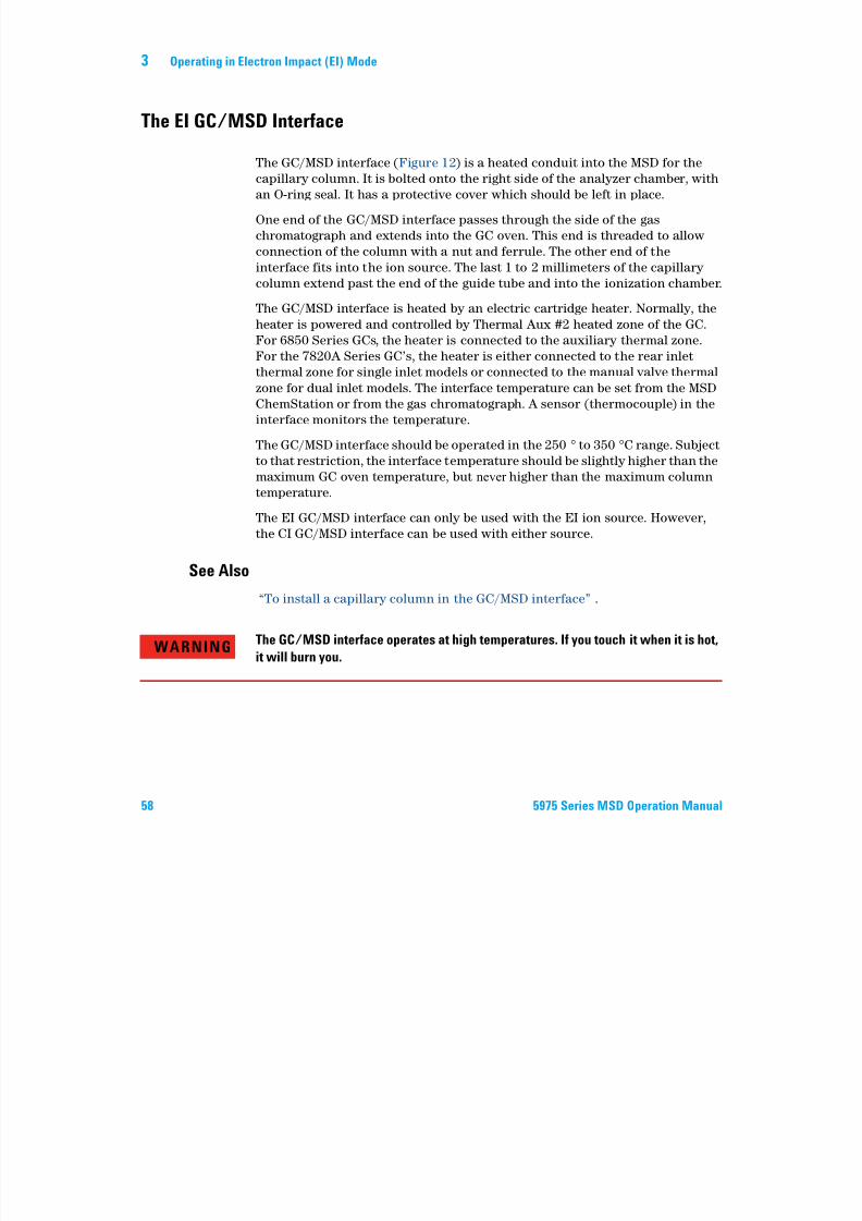
The GC/MSD interface (Figure 12) is a heated conduit into the MSD for the
capillary column. It is bolted onto the right side of the analyzer chamber, with
an O-ring seal. It has a protective cover which should be left in place.
One end of the GC/MSD interface passes through the side of the gas
chromatograph and extends into the GC oven. This end is threaded to allow
connection of the column with a nut and ferrule. The other end of the
interface fits into the ion source. The last 1 to 2 millimeters of the capillary column extend past the end of the guide tube and into the ionization chamber.
The GC/MSD interface is heated by an electric cartridge heater. Normally, the
heater is powered and controlled by Thermal Aux #2 heated zone of the GC.
For 6850 Series GCs, the heater is connected to the auxiliary thermal zone.
For the 7820A Series GC’s, the heater is either connected to the rear inlet
thermal zone for single inlet models or connected to the manual valve thermal
zone for dual inlet models. The interface temperature can be set from the MSDChemStation or from the gas chromatograph. A sensor (thermocouple) in the
interface monitors the temperature.
The GC/MSD interface should be operated in the 250 to 350 C range. Subject
to that restriction, the interface temperature should be slightly higher than the
maximum GC oven temperature, but never higher than the maximum column
temperature.
The EI GC/MSD interface can only be used with the EI ion source. However,the CI GC/MSD interface can be used with either source.
See Also
“To install a capillary column in the GC/MSD interface” .
WARNING The GC/MSD interface operates at high temperatures. If you touch it when it is hot,it will burn you.
Operating in Electron Impact (EI) Mode 3
7/14/2019 Agilent 5973 MS User Manual
http://slidepdf.com/reader/full/agilent-5973-ms-user-manual 59/162
5975 Series MSD Operation Manual 59
Figure 12 The EI GC/MSD interface
Ionization
chamber
Analyzer
chamber
Heater/Sensor
assembly
MSD GC oven
Heater sleeve
Insulation
Column
Column end protrudes 1 to 2 mm into the ionization chamber.
3 Operating in Electron Impact (EI) Mode
Before You Turn On the MSD
7/14/2019 Agilent 5973 MS User Manual
http://slidepdf.com/reader/full/agilent-5973-ms-user-manual 60/162
60 5975 Series MSD Operation Manual
Before You Turn On the MSD
Verify the following before you turn on or attempt to operate the MSD.
• The vent valve must be closed (the knob turned all the way clockwise).
• All other vacuum seals and fittings must be in place and fastened correctly.
(The the front side plate screw should not be tightened, unless hazardous
carrier or reagent gasses are being used.
• The MSD is connected to a grounded power source.
• The GC/MSD interface extends into the GC oven.
• A conditioned capillary column is installed in the GC inlet and in the
GC/MSD interface.
• The GC is on, but the heated zones for the GC/MSD interface, the GC inlet,
and the oven are off.
• Carrier gas of at least 99.9995% purity is plumbed to the GC with the
recommended traps.• If hydrogen is used as carrier gas, carrier gas f low must be off and the front
sideplate thumbscrew must be loosely fastened.
• The foreline pump exhaust is properly vented.
WARNINGThe exhaust from the foreline pump contains solvents and the chemicals you are
analyzing. If using the standard foreline pump, it also contains traces of pump oil. If
you are using toxic solvents or analyzing toxic chemicals, remove the oil trap(standard pump) and install a hose (11-mm id) to take the foreline pump exhaust
outside or to a fume (exhaust) hood. Be sure to comply with local regulations. The
oil trap supplied with the standard pump stops only pump oil. It does not trap or filter
out toxic chemicals.
WARNINGIf you are using hydrogen as a carrier gas, do not start carrier gas flow until the
MSD has been pumped down. If the vacuum pumps are off, hydrogen will
accumulate in the MSD and an explosion may occur. Read “Hydrogen Safety”
before operating the MSD with hydrogen carrier gas.
Operating in Electron Impact (EI) Mode 3
Pumping Down
7/14/2019 Agilent 5973 MS User Manual
http://slidepdf.com/reader/full/agilent-5973-ms-user-manual 61/162
5975 Series MSD Operation Manual 61
p g
The data system or local control panel helps you pump down the MSD. The
process is mostly automated. Once you close the vent valve and turn on the
main power switch (while pressing on the sideplate), the MSD pumps down by
itself. The data system software monitors and displays system status during
pumpdown. When the pressure is low enough, the program turns on the ion
source and mass filter heaters and prompts you to turn on the GC/MSD
interface heater. The MSD will shut down if it cannot pump down correctly.
Using the menus or MS monitors, the data system can display:
• Motor speed for turbo pump MSDs (percent spin speed)
• Foreline pressure for diffusion pump MSDs
• Analyzer chamber pressure (vacuum) for MSDs with the optional G3397A
Micro-Ion Gauge Controller
The LCP can also display these data.
Controlling Temperatures
MSD temperatures are controlled through the data system. The MSD has
independent heaters and temperature sensors for the ion source and
quadrupole mass filter. You can adjust the setpoints and view these
temperatures from the data system or from the local control panel.
Normally, the GC/MSD interface heater is powered and controlled by the
Thermal Aux #2 heated zone of the GC. For the 6850 Series GCs, the heater is
connected to the auxiliary thermal zone. For the 7820 Series GCs, the heater is
either connected to the rear inlet thermal zone for single inlet models or is
connected to the manual valve thermal zone for dual inlet models. The
GC/MSD interface temperature can be set and monitored from the data
system or from the GC.
3 Operating in Electron Impact (EI) Mode
Controlling Column Flow
7/14/2019 Agilent 5973 MS User Manual
http://slidepdf.com/reader/full/agilent-5973-ms-user-manual 62/162
62 5975 Series MSD Operation Manual
g
Carrier gas flow is controlled by head pressure in the GC. For a given head
pressure, column flow will decrease as the GC oven temperature increases.
With electronic pneumatic control (EPC) and the column mode set to Constant
Flow, the same column flow is maintained regardless of temperature.
The MSD can be used to measure actual column flow. You inject a small
amount of air or other unretained chemical and time how long it takes to
reach the MSD. With this time measurement, you can calculate the columnflow. See page 73.
Operating in Electron Impact (EI) Mode 3
Venting the MSD
7/14/2019 Agilent 5973 MS User Manual
http://slidepdf.com/reader/full/agilent-5973-ms-user-manual 63/162
5975 Series MSD Operation Manual 63
A program in the data system guides you through the venting process. It turns
off the GC and MSD heaters and diffusion pump heater or the turbo pump at
the correct time. It also lets you monitor temperatures in the MSD and
indicates when to vent the MSD.
The MSD will be damaged by incorrect venting. A diffusion pump will
backstream vaporized pump fluid onto the analyzer if the MDS is vented
before the diffusion pump has fully cooled. A turbo pump will be damaged if it is vented while spinning at more than 50% of its normal operating speed.
WARNINGMake sure the GC/MSD interface and the analyzer zones are cool (below 100 °C)
before you vent the MSD. A temperature of 100 °C is hot enough to burn skin; always
wear cloth gloves when handling analyzer parts.
WARNINGIf you are using hydrogen as a carrier gas, the carrier gas flow must be off before
turning off the MSD power. If the foreline pump is off, hydrogen will accumulate in
the MSD and an explosion may occur. Read “Hydrogen Safety” before operating
the MSD with hydrogen carrier gas.
CAUTION Never vent the MSD by allowing air in through either end of the foreline hose. Use thevent valve or remove the column nut and column.
Do not vent while the turbo pump is still spinning at more than 50%.
Do not exceed the maximum recommended total gas flow. See “5975 series MSD
models and features” .
3 Operating in Electron Impact (EI) Mode
To view MSD analyzer temperature and vacuum status
7/14/2019 Agilent 5973 MS User Manual
http://slidepdf.com/reader/full/agilent-5973-ms-user-manual 64/162
64 5975 Series MSD Operation Manual
You can also use the Local Control Panel to perform this task. See the
G1701EA GC/MSD ChemStation Getting Started manual for more
information.
Procedure
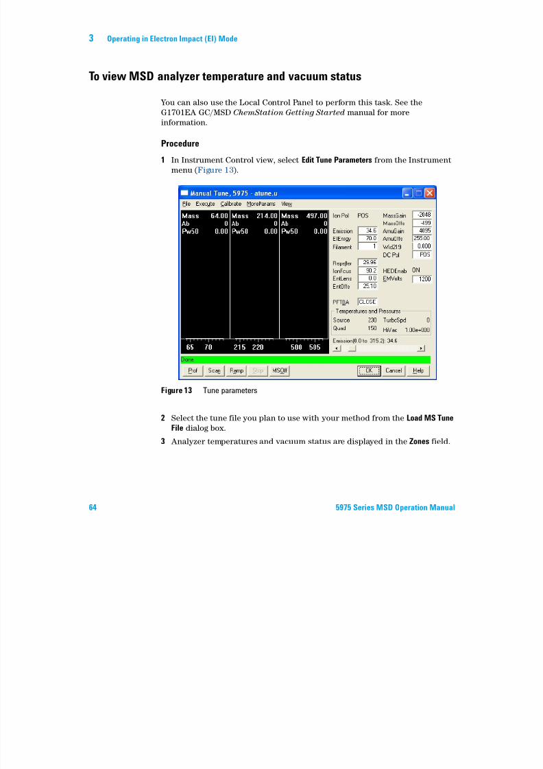
1 In Instrument Control view, select Edit Tune Parameters from the Instrument
menu (Figure 13).
2 Select the tune file you plan to use with your method from the Load MS Tune
File dialog box.
3 Analyzer temperatures and vacuum status are displayed in the Zones field.
Figure 13 Tune parameters
Operating in Electron Impact (EI) Mode 3
Unless you have just begun the pumpdown process, the foreline pressure
should be less than 300 mTorr or the turbo pump should be running at least

7/14/2019 Agilent 5973 MS User Manual
http://slidepdf.com/reader/full/agilent-5973-ms-user-manual 65/162
5975 Series MSD Operation Manual 65
should be less than 300 mTorr, or the turbo pump should be running at least
80% speed. MSD heaters remain off as long as the diffusion pump is cold or theturbo pump is operating at less than 80%. Normally, the foreline pressure will
be below 100 mTorr, or the turbo pump speed will be at 100%.
The MSD heaters turn on at the end of the pumpdown cycle and turn off at the
beginning of the vent cycle. The reported setpoints will not change during
venting or pumpdown, even though both the MSD zones are turned off.
3 Operating in Electron Impact (EI) Mode
To set monitors for MSD temperature and vacuum status
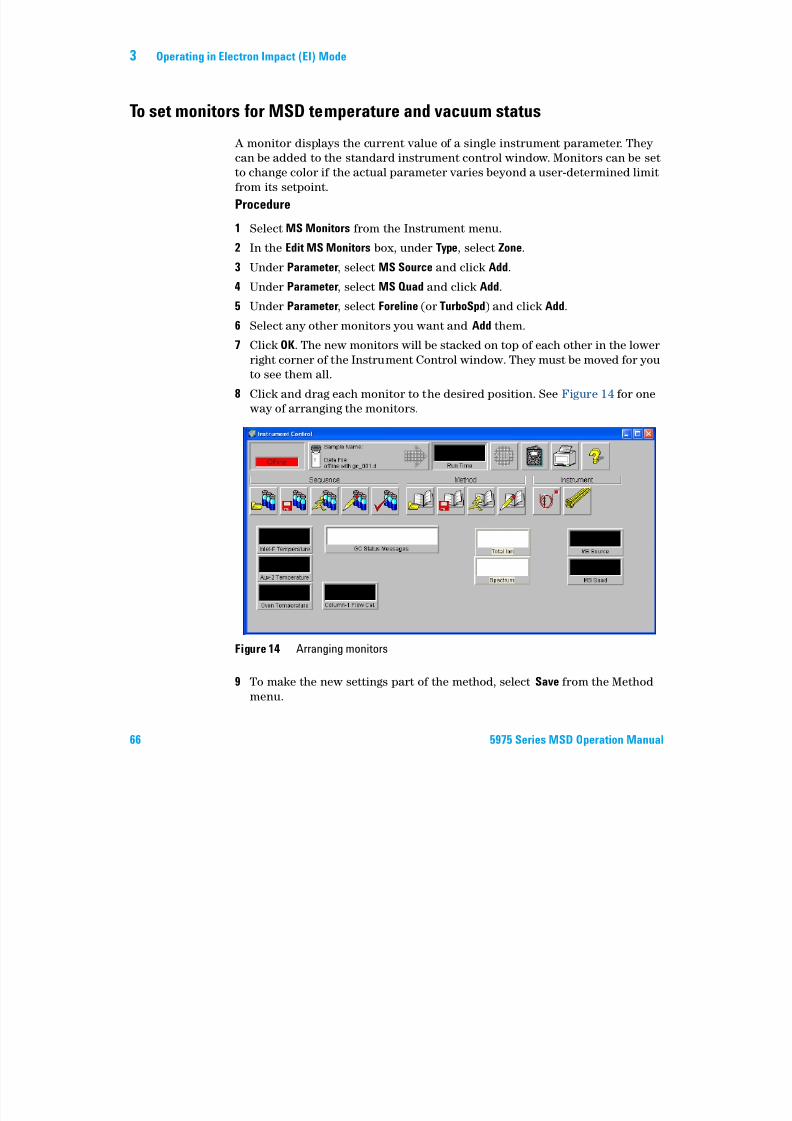
7/14/2019 Agilent 5973 MS User Manual
http://slidepdf.com/reader/full/agilent-5973-ms-user-manual 66/162
66 5975 Series MSD Operation Manual
A monitor displays the current value of a single instrument parameter. They
can be added to the standard instrument control window. Monitors can be set
to change color if the actual parameter varies beyond a user-determined limit
from its setpoint.
Procedure
1 Select MS Monitors from the Instrument menu.
2 In the Edit MS Monitors box, under Type, select Zone.3 Under Parameter, select MS Source and click Add.
4 Under Parameter, select MS Quad and click Add.
5 Under Parameter, select Foreline (or TurboSpd) and click Add.
6 Select any other monitors you want and Add them.
7 Click OK. The new monitors will be stacked on top of each other in the lower
right corner of the Instrument Control window. They must be moved for youto see them all.
8 Click and drag each monitor to the desired position. See Figure 14 for one
way of arranging the monitors.
9 To make the new settings part of the method, select Save from the Method
menu.
Figure 14 Arranging monitors
Operating in Electron Impact (EI) Mode 3
To set the MSD analyzer temperatures
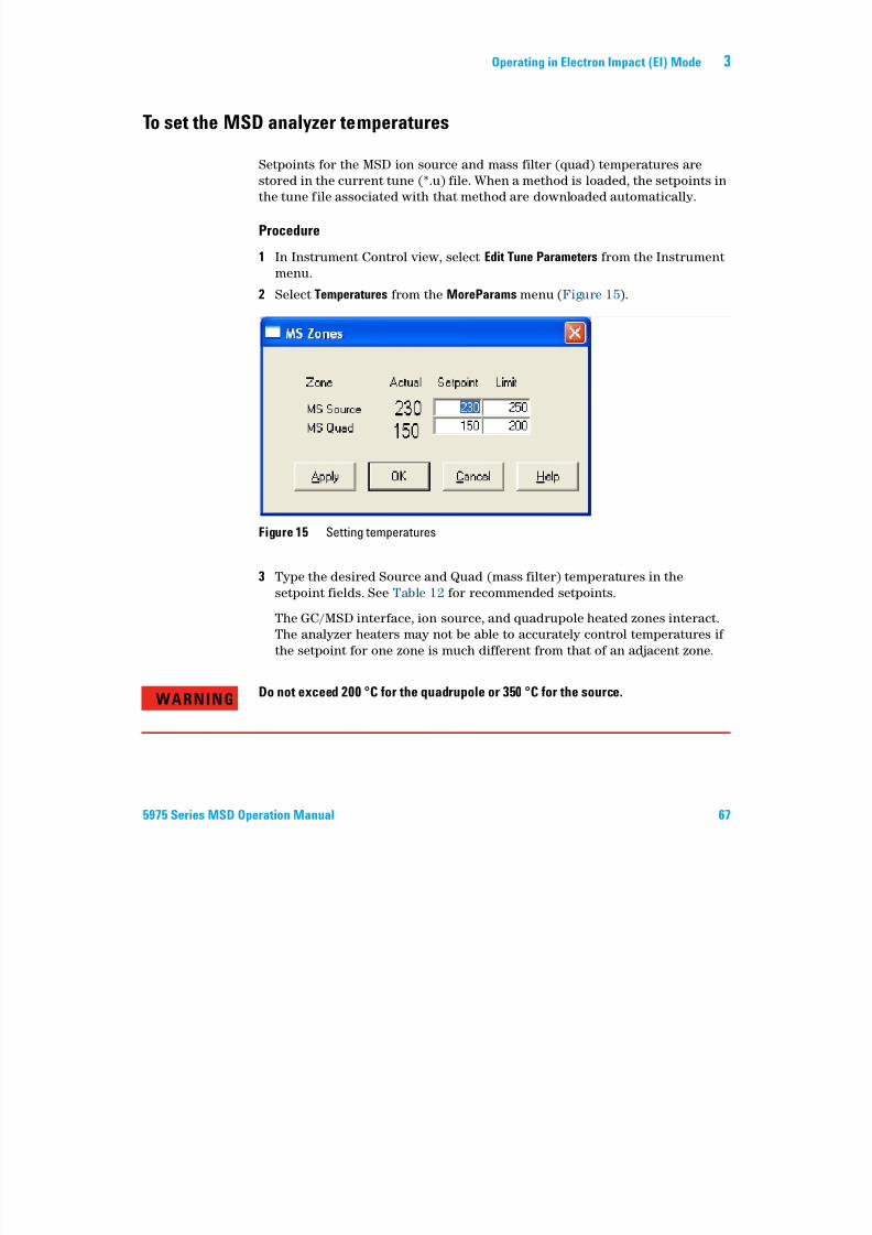
7/14/2019 Agilent 5973 MS User Manual
http://slidepdf.com/reader/full/agilent-5973-ms-user-manual 67/162
5975 Series MSD Operation Manual 67
Setpoints for the MSD ion source and mass filter (quad) temperatures are
stored in the current tune (*.u) file. When a method is loaded, the setpoints in
the tune file associated with that method are downloaded automatically.
Procedure
1 In Instrument Control view, select Edit Tune Parameters from the Instrument
menu.2 Select Temperatures from the MoreParams menu (Figure 15).
3 Type the desired Source and Quad (mass filter) temperatures in the
setpoint fields. See Table 12 for recommended setpoints.
The GC/MSD interface, ion source, and quadrupole heated zones interact.
The analyzer heaters may not be able to accurately control temperatures if
the setpoint for one zone is much different from that of an adjacent zone.
Figure 15 Setting temperatures
WARNINGDo not exceed 200 °C for the quadrupole or 350 °C for the source.
3 Operating in Electron Impact (EI) Mode
4 To close the screen, click:
7/14/2019 Agilent 5973 MS User Manual
http://slidepdf.com/reader/full/agilent-5973-ms-user-manual 68/162
68 5975 Series MSD Operation Manual
• Apply to send the new temperature setpoints to the MSD.• OK to change the currently loaded tune file but not download anything to
the MSD (use Apply).
• Cancel to exit the panel without changing the currently loaded tune file
or downloading anything to the MSD.
5 When the Save MS Tune File dialog box appears, either click OK to save your
changes to the same file or type a new file name and click OK.
Table 12 Recommended temperature settings
EI operation PCI operation NCI operation
MS Source 230 250 150
MS Quad 150 150 150
Operating in Electron Impact (EI) Mode 3
To set the GC/MSD interface temperature from the ChemStation
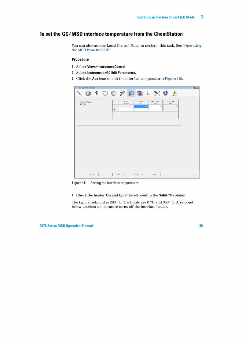
7/14/2019 Agilent 5973 MS User Manual
http://slidepdf.com/reader/full/agilent-5973-ms-user-manual 69/162
5975 Series MSD Operation Manual 69
You can also use the Local Control Panel to perform this task. See “Operating
the MSD from the LCP” .
Procedure
1 Select View>Instrument Control.
2 Select Instrument>GC Edit Parameters.
3 Click the Aux icon to edit the interface temperature (Figure 16).
4 Check the heater On and type the setpoint in the Value °C column.
The typical setpoint is 280 °C. The limits are 0 °C and 350 °C. A setpoint
below ambient temperature turns off the interface heater.
Figure 16 Setting the interface temperature
3 Operating in Electron Impact (EI) Mode
CAUTION
Never exceed the maximum temperature for your column.
7/14/2019 Agilent 5973 MS User Manual
http://slidepdf.com/reader/full/agilent-5973-ms-user-manual 70/162
70 5975 Series MSD Operation Manual
5 Click Apply to download setpoints or click OK to download setpoints and
close the window.
6 To make the new settings part of the method, select Save from the Method
menu.
CAUTION
CAUTIONMake sure that the carrier gas is turned on and the column has been purged of air
before heating the GC/MSD interface or the GC oven.
Operating in Electron Impact (EI) Mode 3
To monitor high vacuum pressure
7/14/2019 Agilent 5973 MS User Manual
http://slidepdf.com/reader/full/agilent-5973-ms-user-manual 71/162
5975 Series MSD Operation Manual 71
Pressure monitoring requires an optional G3397A Micro-Ion vacuum gauge.
Materials needed
• Micro-Ion vacuum gauge (G3397A)
Procedure
1 Start up and pump down the MSD (page 91).
2 In the Tune and Vacuum Control view select Turn Vacuum Gauge on/off from
the Vacuum menu.
3 In the Instrument Control view you can set up an MS Monitor for reading.
The vacuum can also be read on the LCP or from the Manual Tune screen.
The largest influence on operating pressure in EI mode is the carrier gas
(column) flow. Table 13 lists typical pressures for various helium carrier gas
flows. These pressures are approximate and will vary from instrument toinstrument by as much as 30%.
WARNINGIf you are using hydrogen as a carrier gas, do not turn on the Micro-Ion vacuum
gauge if there is any possibility that hydrogen has accumulated in the analyzer
chamber. Read “Hydrogen Safety” before operating the MSD with hydrogen carrier
gas.
3 Operating in Electron Impact (EI) Mode
Table 13 Micro-Ion Vacuum Gauge Reading
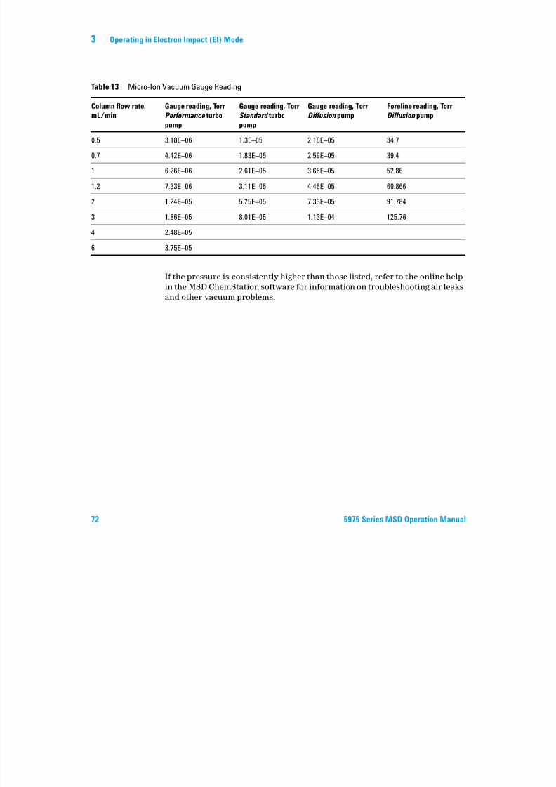
7/14/2019 Agilent 5973 MS User Manual
http://slidepdf.com/reader/full/agilent-5973-ms-user-manual 72/162
72 5975 Series MSD Operation Manual
If the pressure is consistently higher than those listed, refer to the online help
in the MSD ChemStation software for information on troubleshooting air leaks
and other vacuum problems.
Column flow rate,
mL/min
Gauge reading, Torr
Performance turbo
pump
Gauge reading, Torr
Standard turbo
pump
Gauge reading, Torr
Diffusion pump
Foreline reading, Torr
Diffusion pump
0.5 3.18E–06 1.3E–05 2.18E–05 34.7
0.7 4.42E–06 1.83E–05 2.59E–05 39.4
1 6.26E–06 2.61E–05 3.66E–05 52.86
1.2 7.33E–06 3.11E–05 4.46E–05 60.866
2 1.24E–05 5.25E–05 7.33E–05 91.784
3 1.86E–05 8.01E–05 1.13E–04 125.76
4 2.48E–05
6 3.75E–05
Operating in Electron Impact (EI) Mode 3
To measure column flow linear velocity
7/14/2019 Agilent 5973 MS User Manual
http://slidepdf.com/reader/full/agilent-5973-ms-user-manual 73/162
5975 Series MSD Operation Manual 73
With capillary columns, such as those used with the MSD, linear velocity is
often measured rather than volumetric flow rate.
Procedure
1 Set Data Acquisition for splitless manual injection and selected ion
monitoring (SIM) of m/z 28.
2 Press Prep Run on the GC keypad.
3 Inject 1 µL of air into the GC inlet and press Start Run.
4 Wait until a peak elutes at m/z 28. Note the retention time.
5 Calculate the average linear velocity.
Average linear velocity (cm/s) =
where:
L = Length of the column in meters
t = Retention time in seconds
Be sure to account for any pieces of column broken off. A 1-meter section
missing from a 25-meter column can yield a 4% error.
6 Use this velocity to verify the MSD ChemStation flow calculations (page 74).
If the numbers disagree, click Change to calibrate the column dimensions.
7 To calculate the volumetric flow rate.
Volumetric flow rate (mL/min) =
where:
D = Internal column diameter in millimeters
L = Column length in meters
t = Retention time in minutes
100 L
t --------------
0.785 D2 L
t
----------------------------
3 Operating in Electron Impact (EI) Mode
To confirm column flow
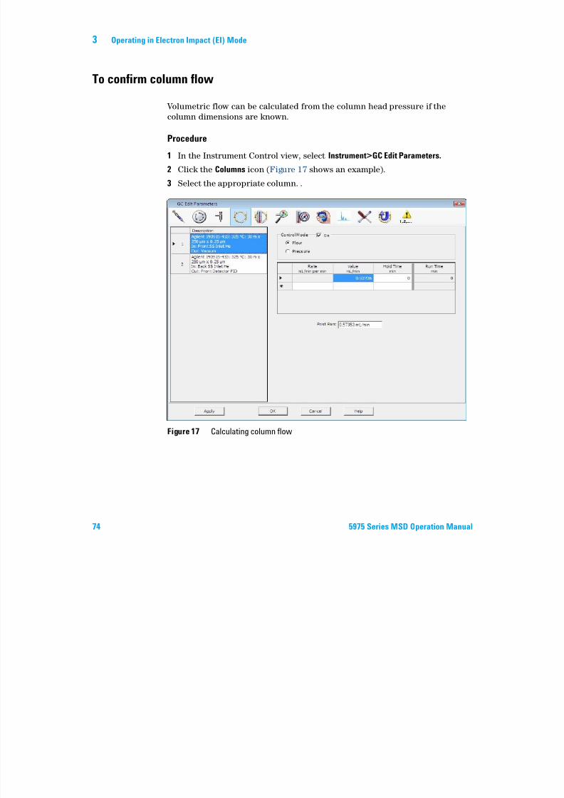
7/14/2019 Agilent 5973 MS User Manual
http://slidepdf.com/reader/full/agilent-5973-ms-user-manual 74/162
74 5975 Series MSD Operation Manual
Volumetric flow can be calculated from the column head pressure if the
column dimensions are known.
Procedure
1 In the Instrument Control view, select Instrument>GC Edit Parameters.
2 Click the Columns icon (Figure 17 shows an example).
3 Select the appropriate column. .
Figure 17 Calculating column flow
Operating in Electron Impact (EI) Mode 3
To tune the MSD
Y l h L l C l P l h h i l
7/14/2019 Agilent 5973 MS User Manual
http://slidepdf.com/reader/full/agilent-5973-ms-user-manual 75/162
5975 Series MSD Operation Manual 75
You can also use the Local Control Panel to run the autotune that is currently
loaded in the PC memory. See “Operating the MSD from the LCP” .
Procedure
1 In the Instrument Control View, verify the correct tune file is loaded. For
most applications, ATUNE.U (Autotune) gives good results. STUNE.U
(Standard Tune) is not recommended as it may reduce sensitivity.Consider Gain autotune (GAIN.U + HiSense.U). This tunes to a target gain
rather than a target abundance. It offers excellent reproducibility, both of
run-to-run abundance but also between different instruments,
2 Set the system to the same conditions (GC oven temperature and column
flow, and MSD analyzer temperatures) that will be used for data
acquisition.
3 Select Tune MSD to perform a complete tune, or select Quick Tune to adjust peak width, mass assignment, and abundance, without changing ion ratios.
If your system is configured for CI, you will be able to access the CI Tune
panel from this box. The tune will start immediately.
4 Wait for the tune to complete and to generate the report.
Save your tune reports. To view history of tune results, select
Checkout>View Previous Tunes....
To manually tune your MSD or to perform special autotunes, go to the Tune
and Vacuum Control View.
From this Tune menu, in addition to the tunes available from Instrument
Control, you can select special autotunes for specific spectral results, such as
DFTPP Tune or BFB Tune.
See the manuals or online help provided with your MSD ChemStation software
for additional information about tuning.
3 Operating in Electron Impact (EI) Mode
To verify system performance
Materials needed
7/14/2019 Agilent 5973 MS User Manual
http://slidepdf.com/reader/full/agilent-5973-ms-user-manual 76/162
76 5975 Series MSD Operation Manual
Materials needed
• 1 pg/µL (0.001 ppm) OFN sample (5188-5348)
Verify the tune performance
1 Verify that the system has been pumping down for at least 60 minutes.
2 Set the GC oven temperature to 150 °C and the column flow to 1.0 mL/min.3 In the Instrument Control view, select Checkout Tune from the Checkout
menu. The software will perform an autotune and print the report.
4 When the autotune has completed, save the method and then select
Evaluate Tune from the Checkout menu.
The software will evaluate the last autotune and print a System Verification
– Tune report.
Verify the sensitivity performance
1 Set up to inject 1 µL of OFN, either with the ALS or manually.
2 In the Instrument Control view, select Sensitivity Check from the Checkout
menu.
3 Click the appropriate icons in the Instrument Edit window to edit the
method for the type of injection.
4 Click OK to run the method.
When the method is completed, an evaluation report will be printed.
Verify that rms signal-to-noise ratio meets the published specification.
Please see the Agilent Web site at www.agilent.com/chem for specifications.
Operating in Electron Impact (EI) Mode 3
High-Mass Testing (5975 Series MSDs)
Setup conditions
7/14/2019 Agilent 5973 MS User Manual
http://slidepdf.com/reader/full/agilent-5973-ms-user-manual 77/162
5975 Series MSD Operation Manual 77
Setup conditions
1 Obtain a sample of PFHT (5188-5357).
2 Load tune file ATUNE.U then auto tune the MSD.
3 Resolve the PFHT.M method under x\5975\PFHT.M where x is instrument
number being used.
4 Update and save the method.
High-mass checkout
1 Load sample into a vial and place in position 2.
2 Select High Mass Check from the Checkout menu.
3 Follow the instructions on screen.
4 The Run is completed and results are printed within 5 minutes.
3 Operating in Electron Impact (EI) Mode
Results
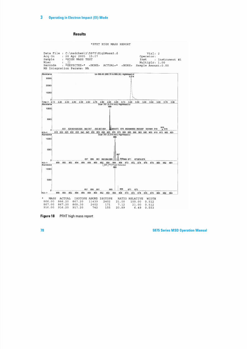
7/14/2019 Agilent 5973 MS User Manual
http://slidepdf.com/reader/full/agilent-5973-ms-user-manual 78/162
78 5975 Series MSD Operation Manual
Figure 18 PFHT high mass report
Operating in Electron Impact (EI) Mode 3
Results will indicate the recommended amount to adjust AMU offset for
high-mass. If your results are within 5 units of the targeted amount, there is no
need to make adjustments.
7/14/2019 Agilent 5973 MS User Manual
http://slidepdf.com/reader/full/agilent-5973-ms-user-manual 79/162
5975 Series MSD Operation Manual 79
Adjustments
1 Verify ATUNE.U has been loaded.
2 Select Edit Tune Parameters from the Instrument menu via Instrument
Control.
3 Click on MoreParams and select DynamicRamping Params...
a Select AMU offset from the drop down box.
b If the values on the right side are greyed out then select the Enable
Dynamic Ramping For This Lens checkbox.
c Enter in the recommend offset and click OK.
4 Click OK on the Edit Parameters box. The Save MS Tune File dialog box
appears.
You can overwrite the existing ATUNE.U to include high-mass adjustment
or save this file to a new name, for example, ATUNEHIGH.U.
5 Load the PFHT.M and the saved tune file, then save the method.
6 Rerun test mixture (repeat high-mass checkout). If the correction is within
5 units, no further adjustments are required.
NOTEAnytime an ATUNE.U is performed it will overwrite the AMU offset which was entered. This
is the reason for renaming the tune.
3 Operating in Electron Impact (EI) Mode
To remove the MSD covers
Materials needed
7/14/2019 Agilent 5973 MS User Manual
http://slidepdf.com/reader/full/agilent-5973-ms-user-manual 80/162
80 5975 Series MSD Operation Manual
• Screwdriver, Torx T-15 (8710-1622)
If you need to remove one of the MSD covers, follow these procedures
(Figure 19):
To remove the analyzer top cover
Remove the five screws and lift the cover off.
To remove the analyzer window cover
1 Press down on the rounded area on the top of the window.
2 Lift the window forward and off the MSD.
WARNINGDo not remove any other covers. Dangerous voltages are present under other covers.
Operating in Electron Impact (EI) Mode 3
Analyzer window cover
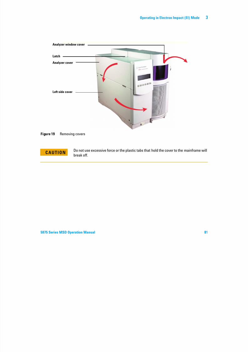
7/14/2019 Agilent 5973 MS User Manual
http://slidepdf.com/reader/full/agilent-5973-ms-user-manual 81/162
5975 Series MSD Operation Manual 81
Figure 19 Removing covers
Latch
Analyzer cover
Left side cover
CAUTION Do not use excessive force or the plastic tabs that hold the cover to the mainframe willbreak off.
3 Operating in Electron Impact (EI) Mode
To vent the MSD
Procedure
7/14/2019 Agilent 5973 MS User Manual
http://slidepdf.com/reader/full/agilent-5973-ms-user-manual 82/162
82 5975 Series MSD Operation Manual
1 Select Vent from the Vacuum menu in the software. Follow the instructions
presented.
2 Set the GC/MSD interface heater and the GC oven temperatures to ambient
(room temperature).
3 When prompted, turn off the MSD power switch.
4 Unplug the MSD power cord.
WARNINGIf you are using hydrogen as a carrier gas, the carrier gas flow must be off before
turning off the MSD power. If the foreline pump is off, hydrogen will accumulate in
the MSD and an explosion may occur. Read “Hydrogen Safety” before operating
the MSD with hydrogen carrier gas.
CAUTION Be sure the GC oven and the GC/MSD interface are cool before turning off carrier gasflow.
WARNINGWhen the MSD is vented, do not put the ChemStation into Instrument Control view.
Doing so will turn on the interface heater.
Operating in Electron Impact (EI) Mode 3
5 Remove the analyzer window cover (page 80)

7/14/2019 Agilent 5973 MS User Manual
http://slidepdf.com/reader/full/agilent-5973-ms-user-manual 83/162
5975 Series MSD Operation Manual 83
6 Turn the vent valve knob (Figure 20) counterclockwise only 3/4 turns or
until you hear the hissing sound of air flowing into the analyzer chamber.
Do not turn the knob too far or the O-ring may fall out of its groove. Be sure
to retighten the knob before pumping down.
Figure 20 Venting the MSD
Vent valve knob YES NO
WARNINGAllow the analyzer to cool to near room temperature before touching it.
CAUTION Always wear clean gloves while handling any parts that go inside the analyzerchamber.
WARNINGWhen the MSD is vented, do not put the ChemStation into Instrument Control view.
Doing so will turn on the interface heater.
3 Operating in Electron Impact (EI) Mode
To open the analyzer chamber
Materials needed
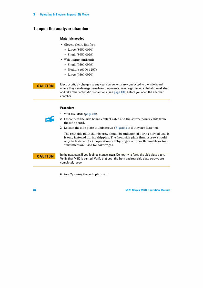
7/14/2019 Agilent 5973 MS User Manual
http://slidepdf.com/reader/full/agilent-5973-ms-user-manual 84/162
84 5975 Series MSD Operation Manual
• Gloves, clean, lint-free
• Large (8650-0030)
• Small (8650-0029)
• Wrist strap, antistatic
• Small (9300-0969)• Medium (9300-1257)
• Large (9300-0970)
Procedure
1 Vent the MSD (page 82).
2 Disconnect the side board control cable and the source power cable from
the side board.
3 Loosen the side plate thumbscrews (Figure 21) if they are fastened.
The rear side plate thumbscrew should be unfastened during normal use. It
is only fastened during shipping. The front side plate thumbscrew should
only be fastened for CI operation or if hydrogen or other flammable or toxic
substances are used for carrier gas.
4 Gently swing the side plate out.
CAUTIONElectrostatic discharges to analyzer components are conducted to the side board
where they can damage sensitive components. Wear a grounded antistatic wrist strap
and take other antistatic precautions (see page 131) before you open the analyzer
chamber.
CAUTION In the next step, if you feel resistance, stop. Do not try to force the side plate open.Verify that MSD is vented. Verify that both the front and rear side plate screws are
completely loose.
Operating in Electron Impact (EI) Mode 3
WARNINGThe analyzer, GC/MSD interface, and other components in the analyzer chamber
operate at very high temperatures. Do not touch any part until you are sure it is cool.
7/14/2019 Agilent 5973 MS User Manual
http://slidepdf.com/reader/full/agilent-5973-ms-user-manual 85/162
5975 Series MSD Operation Manual 85
CAUTIONAlways wear clean gloves to prevent contamination when working in the analyzer
chamber.
3 Operating in Electron Impact (EI) Mode
Thumbscrews
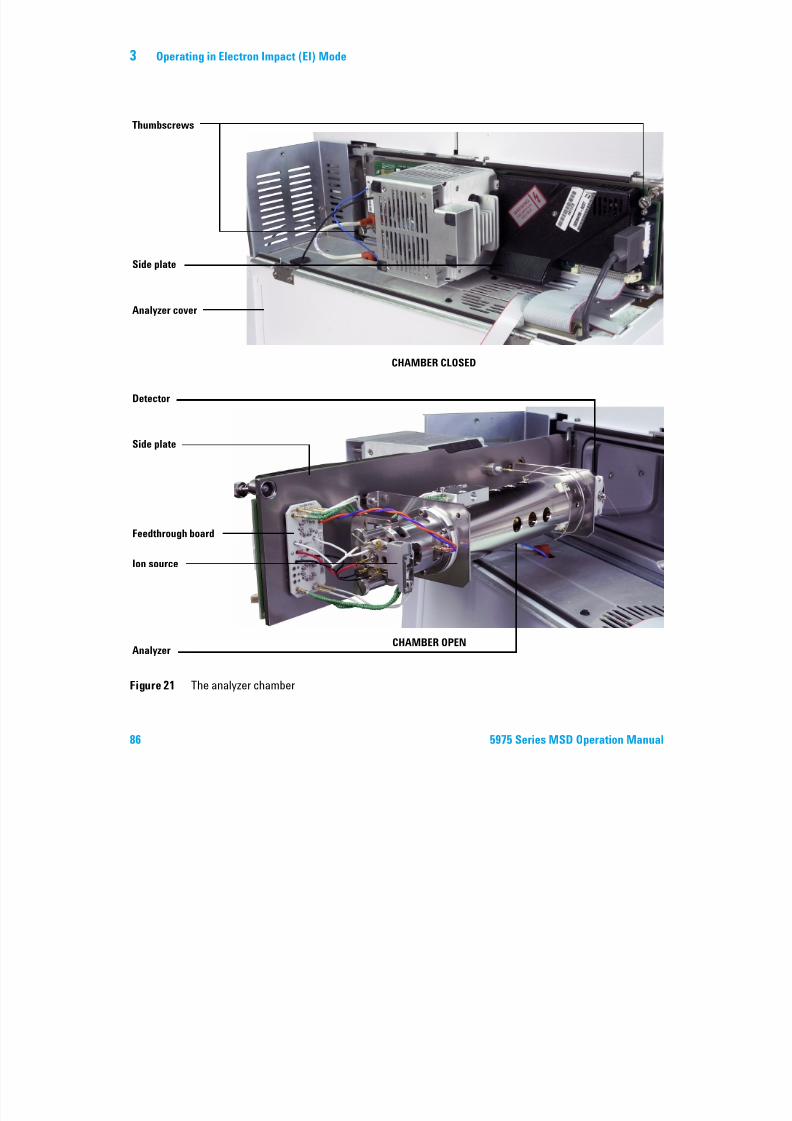
7/14/2019 Agilent 5973 MS User Manual
http://slidepdf.com/reader/full/agilent-5973-ms-user-manual 86/162
86 5975 Series MSD Operation Manual
Figure 21 The analyzer chamber
Side plate
Analyzer cover
Detector
Feedthrough board
Ion source
Analyzer
Side plate
CHAMBER CLOSED
CHAMBER OPEN
Operating in Electron Impact (EI) Mode 3
To close the analyzer chamber
Materials needed
Gl l li f
7/14/2019 Agilent 5973 MS User Manual
http://slidepdf.com/reader/full/agilent-5973-ms-user-manual 87/162
5975 Series MSD Operation Manual 87
• Gloves, clean, lint-free
• Large (8650-0030)
• Small (8650-0029)
Procedure
1 Make sure all the internal analyzer electrical leads are correctly attached.
Wiring is the same for both the EI and CI sources.
The wiring is described in Table 14 and illustrated in Figure 22 and
Figure 23. The term “Board” in the table refers to the feedthrough board
located next to the ion source.
Table 14 Analyzer wiring
Wire description Attached to Connects to
Green beaded (2) Quad heater Board, top left (HTR)
White with braided cover (2) Quad sensor Board, top (RTD)
White (2) Board, center (FILAMENT-1) Filament 1 (top)
Red (1) Board, center left (REP) Repeller
Black (2) Board, center (FILAMENT-2) Filament 2 (bottom)
Orange (1) Board, top right (ION FOC) Ion focus lens
Blue (1) Board, top right (ENT LENS) Entrance lens
Green beaded (2) Ion source heater Board, bottom left (HTR)
White (2) Ion source sensor Board, bottom (RTD)
3 Operating in Electron Impact (EI) Mode
HTR
QUADRUPOLE
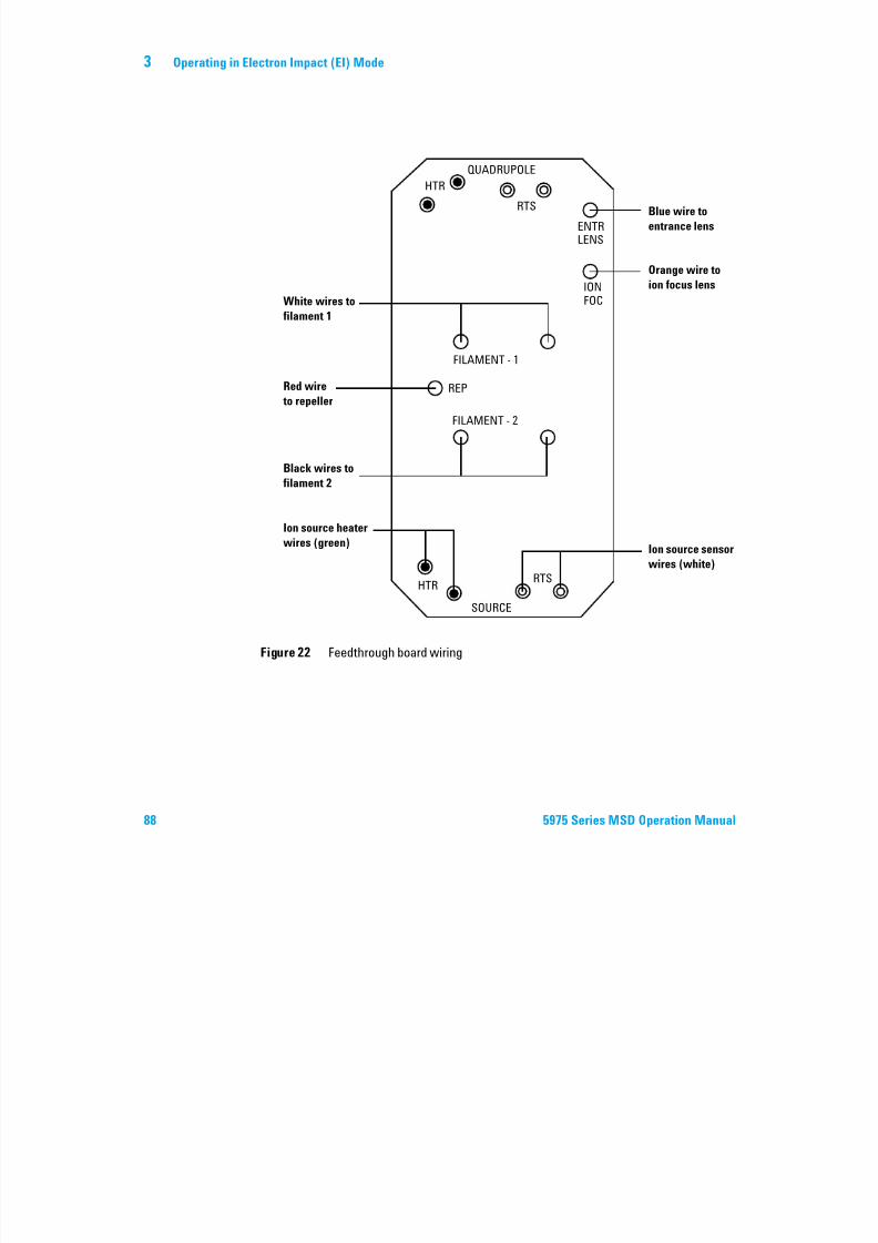
7/14/2019 Agilent 5973 MS User Manual
http://slidepdf.com/reader/full/agilent-5973-ms-user-manual 88/162
88 5975 Series MSD Operation Manual
Figure 22 Feedthrough board wiring
HTRRTS
SOURCE
FILAMENT - 2
FILAMENT - 1
REP
IONFOC
ENTRLENS
RTS
White wires to
filament 1
Red wire
to repeller
Black wires to
filament 2
Ion source heater
wires (green)
Blue wire to
entrance lens
Orange wire to
ion focus lens
Ion source sensor
wires (white)
Operating in Electron Impact (EI) Mode 3
FB = Feedthrough Board
Repeller
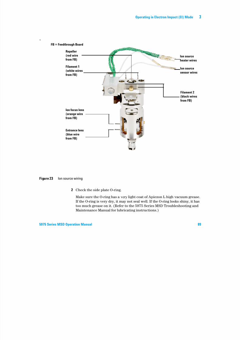
7/14/2019 Agilent 5973 MS User Manual
http://slidepdf.com/reader/full/agilent-5973-ms-user-manual 89/162
5975 Series MSD Operation Manual 89
2 Check the side plate O-ring.
Make sure the O-ring has a very light coat of Apiezon L high vacuum grease.
If the O-ring is very dry, it may not seal well. If the O-ring looks shiny, it has
too much grease on it. (Refer to the 5975 Series MSD Troubleshooting and
Maintenance Manual for lubricating instructions.)
Figure 23 Ion source wiring
Ion source
heater wires
Ion source
sensor wires
p
(red wire
from FB)
Filament 1
(white wires
from FB)
Filament 2
(black wires
from FB)
Ion focus lens
(orange wire
from FB)
Entrance lens
(blue wire
from FB)
3 Operating in Electron Impact (EI) Mode
3 Close the side plate.
4 Reconnect the side board control cable and source power cable to the side
board.
5 Make sure the vent valve is closed.
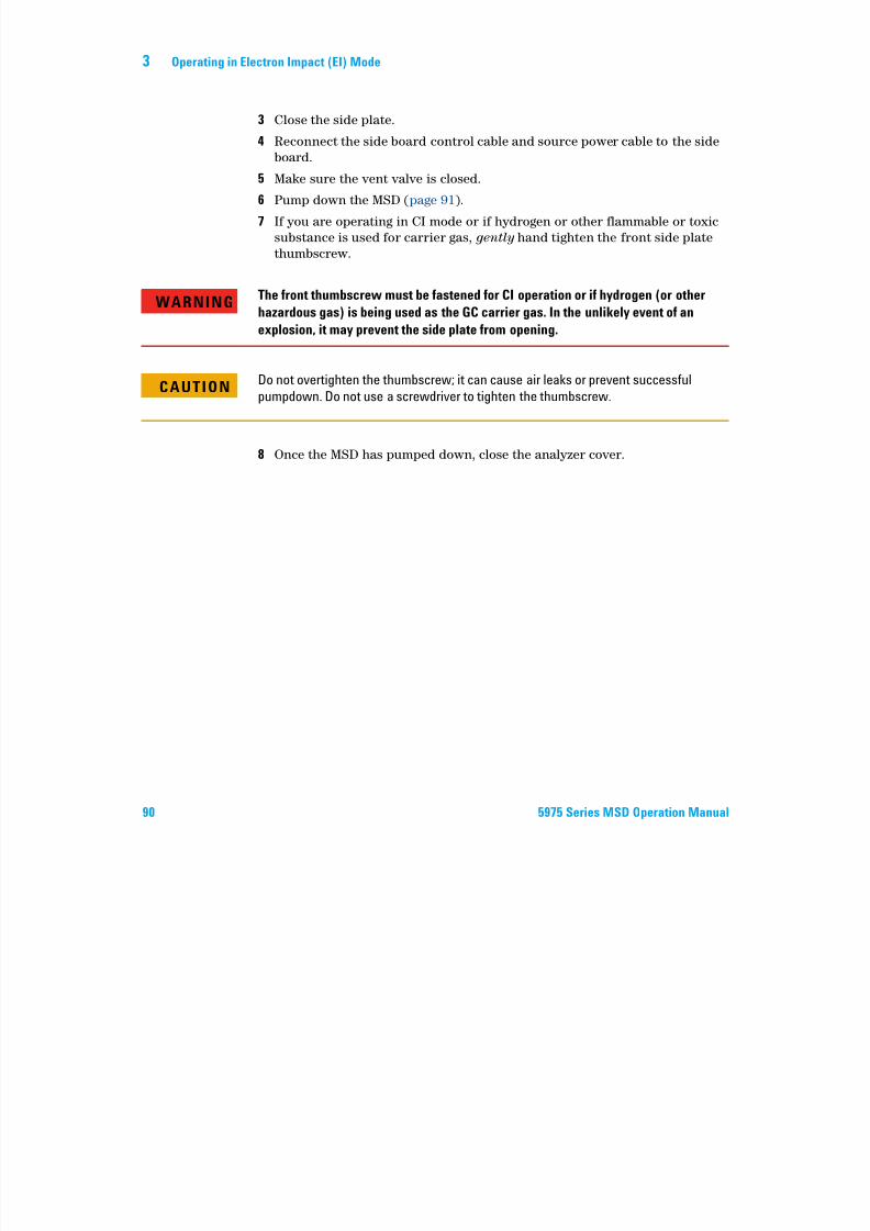
7/14/2019 Agilent 5973 MS User Manual
http://slidepdf.com/reader/full/agilent-5973-ms-user-manual 90/162
90 5975 Series MSD Operation Manual
6 Pump down the MSD (page 91).
7 If you are operating in CI mode or if hydrogen or other flammable or toxic
substance is used for carrier gas, gently hand tighten the front side plate
thumbscrew.
8 Once the MSD has pumped down, close the analyzer cover.
WARNINGThe front thumbscrew must be fastened for CI operation or if hydrogen (or other
hazardous gas) is being used as the GC carrier gas. In the unlikely event of an
explosion, it may prevent the side plate from opening.
CAUTIONDo not overtighten the thumbscrew; it can cause air leaks or prevent successful
pumpdown. Do not use a screwdriver to tighten the thumbscrew.
Operating in Electron Impact (EI) Mode 3
To pump down the MSD
You can also use the Local Control Panel to perform this task. See “Operating
the MSD from the LCP” .
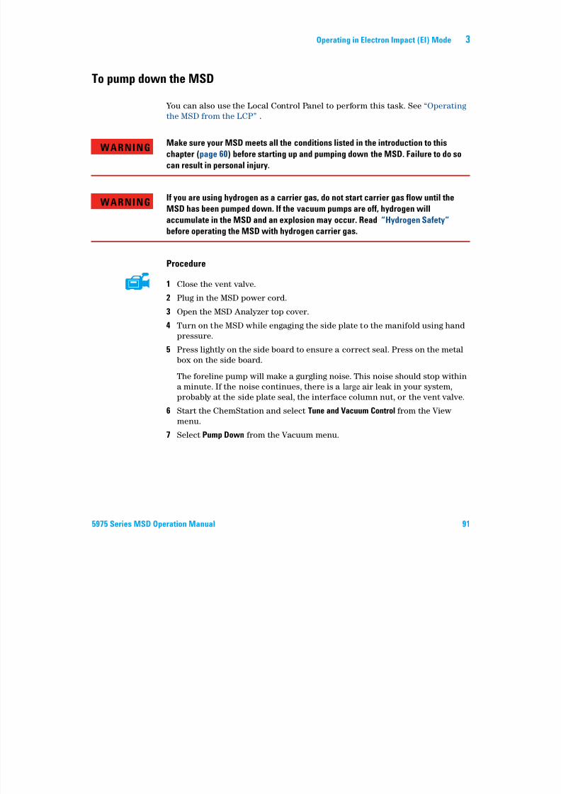
7/14/2019 Agilent 5973 MS User Manual
http://slidepdf.com/reader/full/agilent-5973-ms-user-manual 91/162
5975 Series MSD Operation Manual 91
Procedure
1 Close the vent valve.
2 Plug in the MSD power cord.
3 Open the MSD Analyzer top cover.
4 Turn on the MSD while engaging the side plate to the manifold using hand
pressure.
5 Press lightly on the side board to ensure a correct seal. Press on the metal
box on the side board.
The foreline pump will make a gurgling noise. This noise should stop within
a minute. If the noise continues, there is a large air leak in your system,
probably at the side plate seal, the interface column nut, or the vent valve.
6 Start the ChemStation and select Tune and Vacuum Control from the View
menu.
7 Select Pump Down from the Vacuum menu.
WARNINGMake sure your MSD meets all the conditions listed in the introduction to this
chapter (page 60) before starting up and pumping down the MSD. Failure to do so
can result in personal injury.
WARNINGIf you are using hydrogen as a carrier gas, do not start carrier gas flow until the
MSD has been pumped down. If the vacuum pumps are off, hydrogen will
accumulate in the MSD and an explosion may occur. Read “Hydrogen Safety”
before operating the MSD with hydrogen carrier gas.
3 Operating in Electron Impact (EI) Mode
8 Once communication with the PC has been established, click OK.
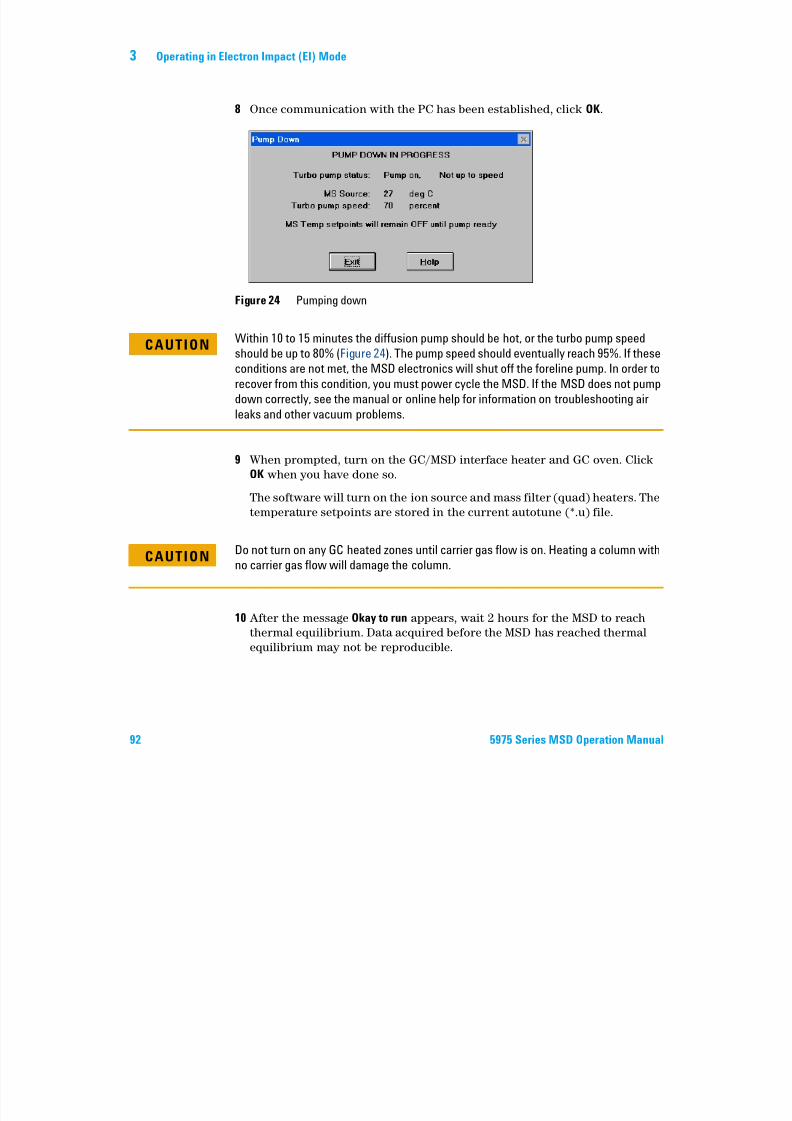
7/14/2019 Agilent 5973 MS User Manual
http://slidepdf.com/reader/full/agilent-5973-ms-user-manual 92/162
92 5975 Series MSD Operation Manual
9 When prompted, turn on the GC/MSD interface heater and GC oven. Click
OK when you have done so.
The software will turn on the ion source and mass filter (quad) heaters. The
temperature setpoints are stored in the current autotune (*.u) file.
10 After the message Okay to run appears, wait 2 hours for the MSD to reach
thermal equilibrium. Data acquired before the MSD has reached thermal
equilibrium may not be reproducible.
Figure 24 Pumping down
CAUTIONWithin 10 to 15 minutes the diffusion pump should be hot, or the turbo pump speed
should be up to 80% (Figure 24). The pump speed should eventually reach 95%. If these
conditions are not met, the MSD electronics will shut off the foreline pump. In order torecover from this condition, you must power cycle the MSD. If the MSD does not pump
down correctly, see the manual or online help for information on troubleshooting air
leaks and other vacuum problems.
CAUTIONDo not turn on any GC heated zones until carrier gas flow is on. Heating a column with
no carrier gas flow will damage the column.
Operating in Electron Impact (EI) Mode 3
To move or store the MSD
Materials needed
• Ferrule, blank (5181-3308)
7/14/2019 Agilent 5973 MS User Manual
http://slidepdf.com/reader/full/agilent-5973-ms-user-manual 93/162
5975 Series MSD Operation Manual 93
• Interface column nut (05988-20066)
• Wrench, open-end, 1/4-inch × 5/16-inch (8710-0510)
Procedure
1 Vent the MSD (page 82).
2 Remove the column and install a blank ferrule and interface nut.
3 Tighten the vent valve.
4 Move the MSD away from the GC (see the 5975 Series MSD Troubleshooting
and Maintenance Manual).
5 Unplug the GC/MSD interface heater cable from the GC.
6 Install the interface nut with the blank ferrule.
7 Open the analyzer cover (page 80).
8 Finger-tighten the side plate thumbscrews (Figure 25).
9 Plug the MSD power cord in.
10 Switch the MSD on to establish a rough vacuum. Verify that the turbo pump
speed is greater than 50% or that the foreline pressure is 1 Torr.
11 Switch the MSD off.
12Close the analyzer cover.
13 Disconnect the LAN, remote, and power cables.
CAUTIONDo not overtighten the side plate thumbscrews. Overtightening will strip the threads in
the analyzer chamber. It will also warp the side plate and cause leaks.
3 Operating in Electron Impact (EI) Mode
Front thumbscrew

7/14/2019 Agilent 5973 MS User Manual
http://slidepdf.com/reader/full/agilent-5973-ms-user-manual 94/162
94 5975 Series MSD Operation Manual
The MSD can now be stored or moved. The foreline pump cannot be
disconnected; it must be moved with the MSD. Make sure the MSD remains
upright and is never tipped on its side or inverted.
Figure 25 Side plate thumbscrews
Rear thumbscrew
CAUTION The MSD must remain upright at all times. If you need to ship your MSD to anotherlocation, contact your Agilent Technologies service representative for advice about
packing and shipping.
Operating in Electron Impact (EI) Mode 3
To set the interface temperature from the GC
If desired, the interface temperature can be set directly at the GC. For the
Agilent 7890A and 6890, set the Aux #2 temperature. For the 6850, use the
optional handheld controller to set the thermal aux temperature. Refer to the

7/14/2019 Agilent 5973 MS User Manual
http://slidepdf.com/reader/full/agilent-5973-ms-user-manual 95/162
5975 Series MSD Operation Manual 95
GC User documentation for details.
If you want the new setpoint to become part of the current method, click Save under the Method menu. Otherwise, the first time a method is loaded, all the
setpoints in the method will overwrite those set from the GC keyboard.
CAUTIONNever exceed the maximum temperature of your column.
CAUTIONMake sure that the carrier gas is turned on and the column has been purged of air
before heating the GC/MSD interface or the GC oven.
3 Operating in Electron Impact (EI) Mode

7/14/2019 Agilent 5973 MS User Manual
http://slidepdf.com/reader/full/agilent-5973-ms-user-manual 96/162
96 5975 Series MSD Operation Manual
Agilent 5975 Series MSD
Operation Manual
4Operating in Chemical Ionization (CI)
Mode
7/14/2019 Agilent 5973 MS User Manual
http://slidepdf.com/reader/full/agilent-5973-ms-user-manual 97/162
97Agilent Technologies
Mode
General Guidelines 98
The CI GC/MSD Interface 99
To Operate the CI MSD 101To switch from the EI source to the CI source 102
To pump down the CI MSD 103
To set up the software for CI operation 104
To operate the reagent gas flow control module 106
To set up methane reagent gas flow 109
To use other reagent gases 111
To switch from the CI source to the EI source 115
CI Autotune 116
To perform a PCI autotune (methane only) 118
To perform an NCI autotune (methane reagent gas) 120
To verify PCI performance 122
To verify NCI performance 123
To monitor high vacuum pressure 124
This chapter provides information and instructions for operating the
5975 Series CI MSDs in Chemical Ionization (CI) mode. Most of the
information in the preceding chapter is also relevant.
Most of the material is related to methane chemical ionization but one sectiondiscusses the use of other reagent gases.
The software contains instructions for setting the reagent gas flow and for
performing CI autotunes. Autotunes are provided for positive CI (PCI) with
methane reagent gas and for negative CI (NCI) with any reagent gas.
4 Operating in Chemical Ionization (CI) Mode
General Guidelines
• Always use the highest purity methane (and other reagent gases, if
applicable.) Methane must be at least 99.9995% pure.
• Always verify the MSD is performing well in EI mode before switching to CI.
7/14/2019 Agilent 5973 MS User Manual
http://slidepdf.com/reader/full/agilent-5973-ms-user-manual 98/162
98 5975 Series MSD Operation Manual
See “To verify system performance” .
• Make sure the CI ion source and GC/MSD interface tip seal are installed.
• Make sure the reagent gas plumbing has no air leaks. This is determined in
PCI mode, checking for m/z 32 after the methane pretune.
Operating in Chemical Ionization (CI) Mode 4
The CI GC/MSD Interface
The CI GC/MSD interface (Figure 26) is a heated conduit into the MSD for the
capillary column. It is bolted onto the right side of the analyzer chamber, with
an O-ring seal and has a protective cover which should be left in place.
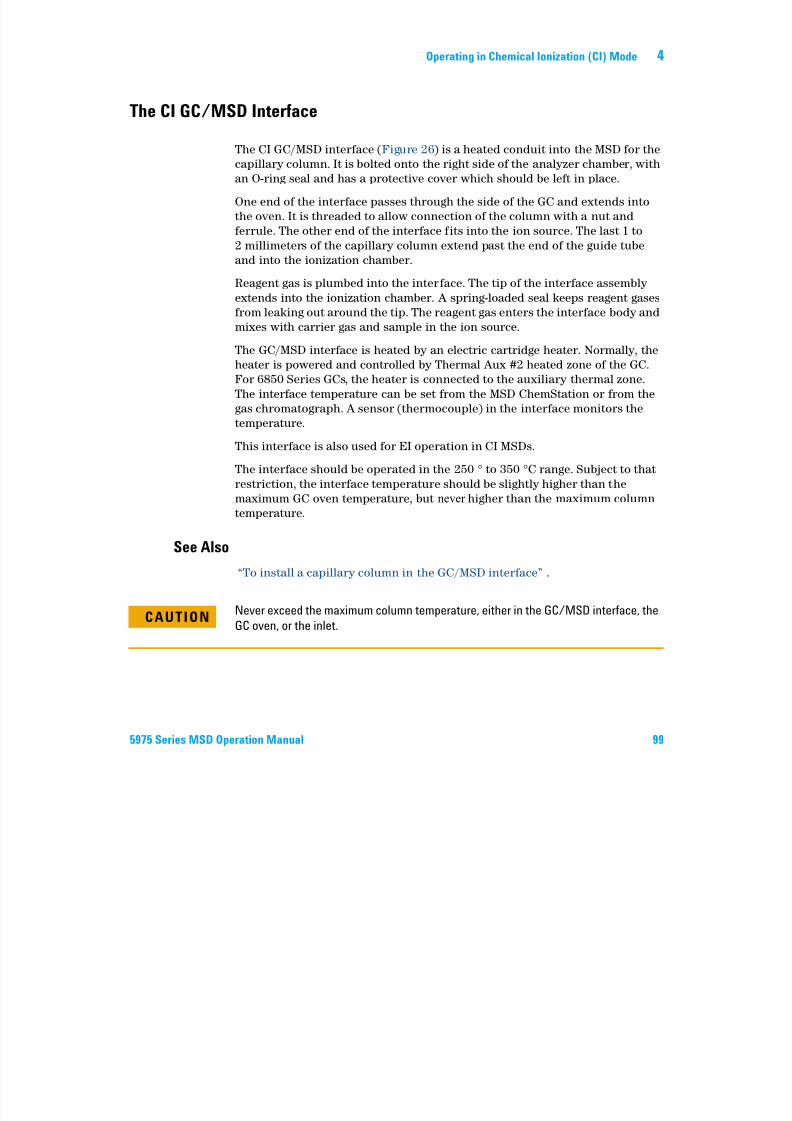
7/14/2019 Agilent 5973 MS User Manual
http://slidepdf.com/reader/full/agilent-5973-ms-user-manual 99/162
5975 Series MSD Operation Manual 99
One end of the interface passes through the side of the GC and extends into
the oven. It is threaded to allow connection of the column with a nut and
ferrule. The other end of the interface fits into the ion source. The last 1 to
2 millimeters of the capillary column extend past the end of the guide tube
and into the ionization chamber.
Reagent gas is plumbed into the interface. The tip of the interface assembly
extends into the ionization chamber. A spring-loaded seal keeps reagent gases
from leaking out around the tip. The reagent gas enters the interface body and
mixes with carrier gas and sample in the ion source.
The GC/MSD interface is heated by an electric cartridge heater. Normally, the
heater is powered and controlled by Thermal Aux #2 heated zone of the GC.
For 6850 Series GCs, the heater is connected to the auxiliary thermal zone.
The interface temperature can be set from the MSD ChemStation or from the
gas chromatograph. A sensor (thermocouple) in the interface monitors the
temperature.
This interface is also used for EI operation in CI MSDs.
The interface should be operated in the 250 to 350 C range. Subject to that
restriction, the interface temperature should be slightly higher than themaximum GC oven temperature, but never higher than the maximum column
temperature.
See Also
“To install a capillary column in the GC/MSD interface” .
CAUTIONNever exceed the maximum column temperature, either in the GC/MSD interface, the
GC oven, or the inlet.
4 Operating in Chemical Ionization (CI) Mode
WARNINGThe GC/MSD interface operates at high temperatures. If you touch it when it is hot,
it will burn you.
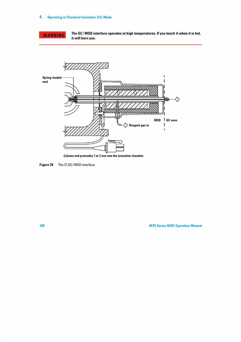
7/14/2019 Agilent 5973 MS User Manual
http://slidepdf.com/reader/full/agilent-5973-ms-user-manual 100/162
100 5975 Series MSD Operation Manual
Figure 26 The CI GC/MSD interface
Spring-loadedseal
Reagent gas in
MSD GC oven
Column end protrudes 1 to 2 mm into the ionization chamber.
Operating in Chemical Ionization (CI) Mode 4
To Operate the CI MSD
Operating your MSD in the CI mode is slightly more complicated than
operating in the EI mode. After tuning, gas flow, source temperature
(Table 15), and electron energy may need to be optimized for your specific
analyte.
7/14/2019 Agilent 5973 MS User Manual
http://slidepdf.com/reader/full/agilent-5973-ms-user-manual 101/162
5975 Series MSD Operation Manual 101
y
Start the system in PCI mode
By bringing the system up in PCI mode first, you will be able to do the
following:
• Set up the MSD with methane first, even if you are going to use another
reagent gas.
• Check the interface tip seal by looking at the m/z 28 to 27 ratio (in the
methane flow adjust panel).
• Tell if a gross air leak is present by monitoring the ions at m/z 19
(protonated water) and 32.
• Confirm that the MS is generating “real” ions and not just background
noise.
It is nearly impossible to perform any diagnostics on the system in NCI. In
NCI, there are no reagent gas ions to monitor. It is difficult to diagnose an air
leak and difficult to tell whether a good seal is being created between the
interface and the ion volume.
Table 15 Temperatures for CI operation
Ion source Quadrupole GC/MSDinterface
PCI 250 °C 150 °C 280 °C
NCI 150 °C 150 °C 280 °C
4 Operating in Chemical Ionization (CI) Mode
To switch from the EI source to the CI source
CAUTIONAlways verify MSD performance in EI before switching to CI operation.
Always set up the CI MSD in PCI first, even if you are going to run NCI.
7/14/2019 Agilent 5973 MS User Manual
http://slidepdf.com/reader/full/agilent-5973-ms-user-manual 102/162
102 5975 Series MSD Operation Manual
Procedure
1 Vent the MSD. See page 82.2 Open the analyzer.
3 Remove the EI ion source. See page 134.
4 Install the CI ion source. See page 142.
5 Install the interface tip seal. See page 143.
6 Close the analyzer.
7 Pump down the MSD. See page 103.
CAUTIONElectrostatic discharges to analyzer components are conducted to the side board
where they can damage sensitive components. Wear a grounded antistatic wrist strap.
See “Electrostatic discharge” . Take antistatic precautions before you open the
analyzer chamber.
Operating in Chemical Ionization (CI) Mode 4
To pump down the CI MSD
You can also use the Local Control Panel to perform this task. See “Operatingthe MSD from the LCP” .
Procedure
7/14/2019 Agilent 5973 MS User Manual
http://slidepdf.com/reader/full/agilent-5973-ms-user-manual 103/162
5975 Series MSD Operation Manual 103
1 Follow the instructions for the EI MSD. See “To pump down the MSD” .
After the software prompts you to turn on the interface heater and GC
oven, perform the following steps.2 Check the vacuum gauge, if present, to verify that the pressure is
decreasing.
3 Press Shutoff Valve to close the gas supply and shutoff valves.
4 Verify that PCICH4.U is loaded and accept the temperature setpoints.
Always start up and verify system performance in PCI mode before
switching to NCI.
5 Set the GC/MSD interface to 280 °C.
6 Set Gas A to 20%.
7 Let the system bake out and purge for at least 2 hours. If you will be
running NCI, best sensitivity, bake out the MSD overnight.
4 Operating in Chemical Ionization (CI) Mode
To set up the software for CI operation
Procedure
1 Switch to the Tune and Vacuum Control view.
2 Select Load Tune Values from the File menu.
7/14/2019 Agilent 5973 MS User Manual
http://slidepdf.com/reader/full/agilent-5973-ms-user-manual 104/162
104 5975 Series MSD Operation Manual
3 Select the tune file PCICH4.U.
4 If CI autotune has never been run for this tune file, the software will
prompt you through a series of dialog boxes. Accept the default values
unless you have a very good reason for changing anything.
The tune values have a dramatic effect on MSD performance. Always start
with the default values when first setting up for CI, and then make
adjustments for your specific application. See Table 16 for default values
for the Tune Control Limits box.
NOTEThese limits are used by Autotune only. They should not be confused with the parameters
set in Edit MS Parameters or with those appearing on the tune report.
Operating in Chemical Ionization (CI) Mode 4
Table 16 Default Tune Control Limits, used by CI autotune only
Reagent gas Methane Isobutane Ammonia
Ion polarity Positive Negative Positive Negative Positive Negative
Abundance target 1x10⁶ 1x10⁶ N/A 1x10⁶ N/A 1x10⁶
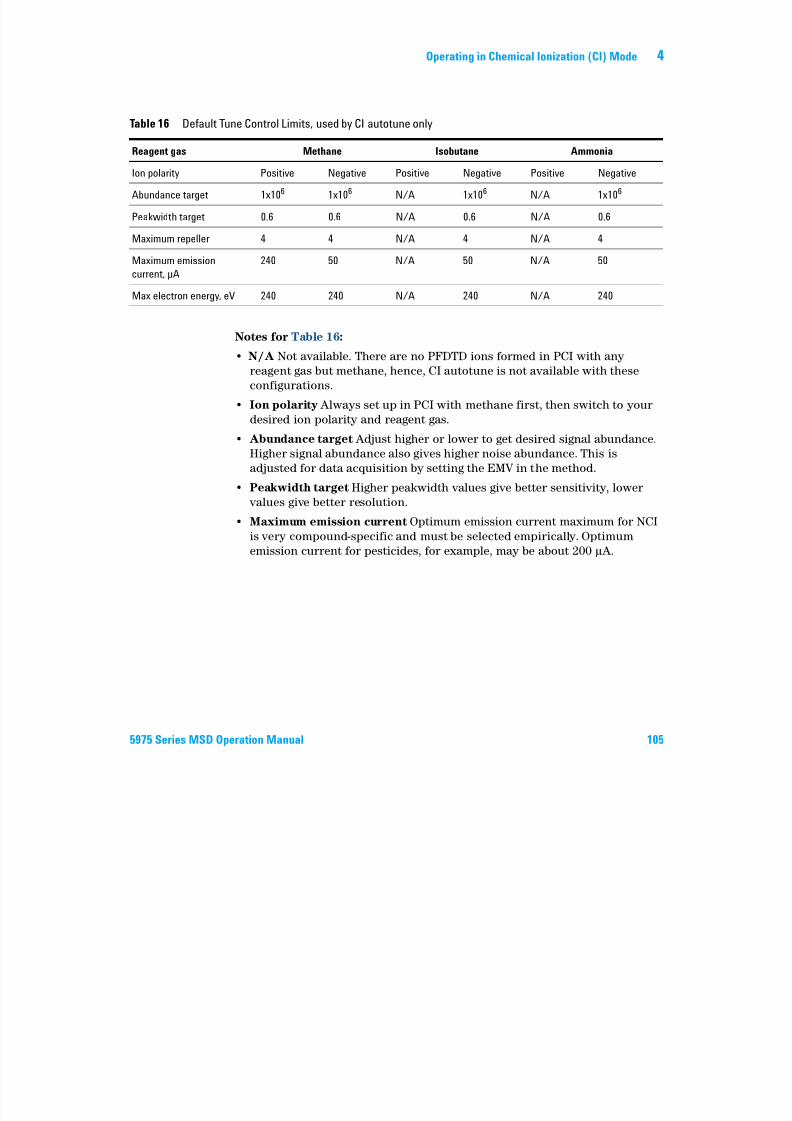
7/14/2019 Agilent 5973 MS User Manual
http://slidepdf.com/reader/full/agilent-5973-ms-user-manual 105/162
5975 Series MSD Operation Manual 105
Notes for Table 16:
• N/A Not available. There are no PFDTD ions formed in PCI with any
reagent gas but methane, hence, CI autotune is not available with theseconfigurations.
• Ion polarity Always set up in PCI with methane first, then switch to your
desired ion polarity and reagent gas.
• Abundance target Adjust higher or lower to get desired signal abundance.
Higher signal abundance also gives higher noise abundance. This is
adjusted for data acquisition by setting the EMV in the method.
• Peakwidth target Higher peakwidth values give better sensitivity, lower values give better resolution.
• Maximum emission current Optimum emission current maximum for NCI
is very compound-specific and must be selected empirically. Optimum
emission current for pesticides, for example, may be about 200 µA.
Peakwidth target 0.6 0.6 N/A 0.6 N/A 0.6
Maximum repeller 4 4 N/A 4 N/A 4
Maximum emissioncurrent, µA
240 50 N/A 50 N/A 50
Max electron energy, eV 240 240 N/A 240 N/A 240
4 Operating in Chemical Ionization (CI) Mode
To operate the reagent gas flow control module
Reagent gas flows are controlled in software (Figure 27).
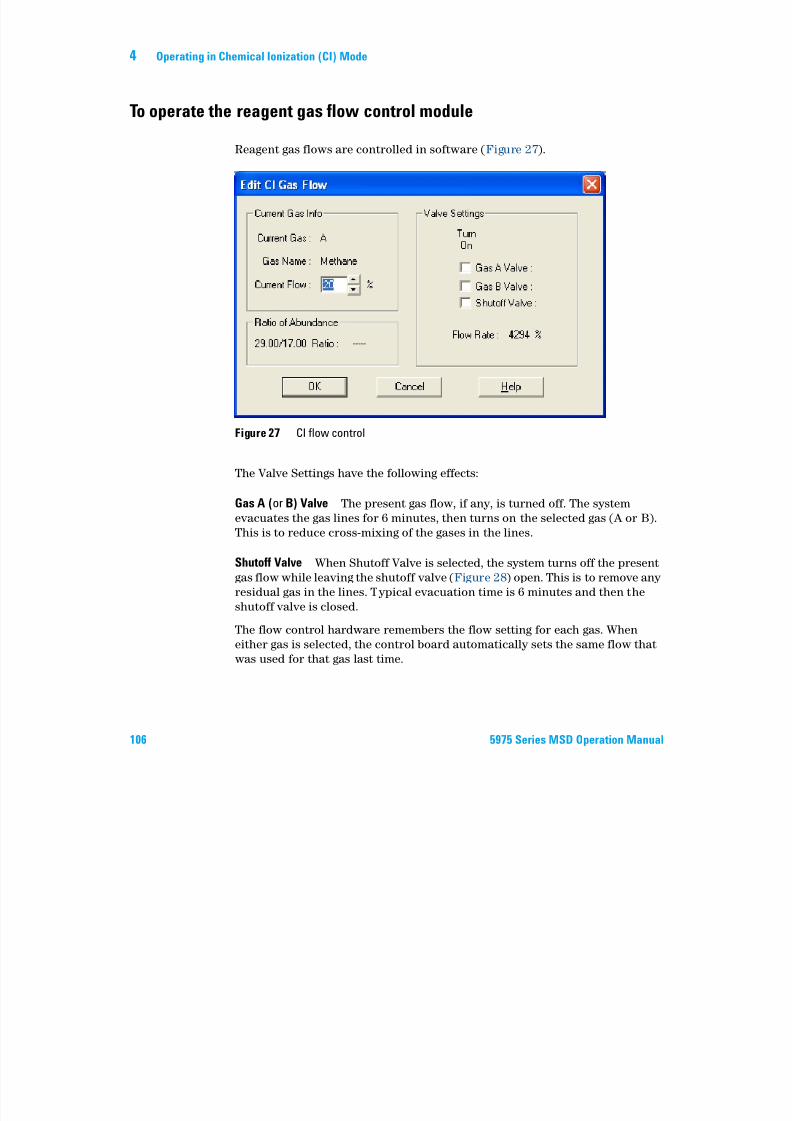
7/14/2019 Agilent 5973 MS User Manual
http://slidepdf.com/reader/full/agilent-5973-ms-user-manual 106/162
106 5975 Series MSD Operation Manual
The Valve Settings have the following effects:
Gas A (or B) Valve The present gas flow, if any, is turned off. The system
evacuates the gas lines for 6 minutes, then turns on the selected gas (A or B).
This is to reduce cross-mixing of the gases in the lines.
Shutoff Valve When Shutoff Valve is selected, the system turns off the present
gas flow while leaving the shutoff valve (Figure 28) open. This is to remove any
residual gas in the lines. Typical evacuation time is 6 minutes and then the
shutoff valve is closed.
The flow control hardware remembers the flow setting for each gas. When
either gas is selected, the control board automatically sets the same flow that
was used for that gas last time.
Figure 27 CI flow control
Operating in Chemical Ionization (CI) Mode 4
The flow control module
The CI reagent gas flow control module (Figure 28 and Table 17) regulates the
flow of reagent gas into the CI GC/MSD interface. The flow module consists of a mass flow controller (MFC), gas select valves, CI calibration valve, shutoff
valve, control electronics, and plumbing.
The back panel provides Swagelok inlet fittings for methane (CH4) and one
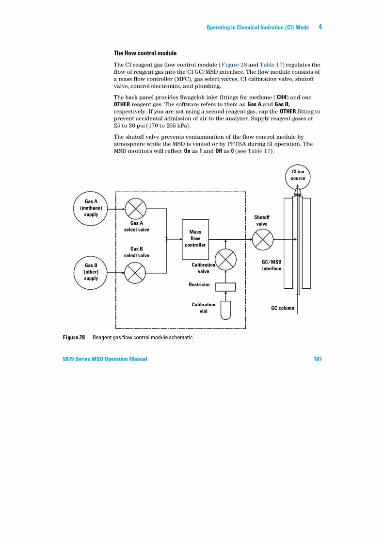
7/14/2019 Agilent 5973 MS User Manual
http://slidepdf.com/reader/full/agilent-5973-ms-user-manual 107/162
5975 Series MSD Operation Manual 107
OTHER reagent gas. The software refers to them as Gas A and Gas B,
respectively. If you are not using a second reagent gas, cap the OTHER fitting to
prevent accidental admission of air to the analyzer. Supply reagent gases at
25 to 30 psi (170 to 205 kPa).
The shutoff valve prevents contamination of the flow control module by
atmosphere while the MSD is vented or by PFTBA during EI operation. The
MSD monitors will reflect On as 1 and Off as 0 (see Table 17).
Figure 28 Reagent gas flow control module schematic
Gas A
(methane)
supply
Gas B
(other)
supply
Gas A
select valve
Gas B
select valve
Mass
flowcontroller
Calibration
valve
Restrictor
Calibration
vial
Shutoff
valve
GC/MSD
interface
GC column
CI ion
source
4 Operating in Chemical Ionization (CI) Mode
Table 17 Flow control module state diagram
Result Gas A flow Gas B flow Purge
with Gas A
Purge
with Gas B
Pump out
flow module
Standby,
vented, or EI
mode
Gas A Open Closed Open Closed Closed Closed

7/14/2019 Agilent 5973 MS User Manual
http://slidepdf.com/reader/full/agilent-5973-ms-user-manual 108/162
108 5975 Series MSD Operation Manual
The Open and Closed states are shown in the monitors as 1 and 0 respectively.
Gas B Closed Open Closed Open Closed Closed
MFC On setpoint On setpoint On 100% On 100% On 100% Off 0%
Shutoff valve Open Open Open Open Open Closed
Operating in Chemical Ionization (CI) Mode 4
To set up methane reagent gas flow
The reagent gas flow must be adjusted for maximum stability before tuning theCI system. Do the initial setup with methane in positive chemical ionization
(PCI) mode. No flow adjustment procedure is available for NCI, as no negative
reagent ions are formed.
Adj ti th th t fl i th t tti th
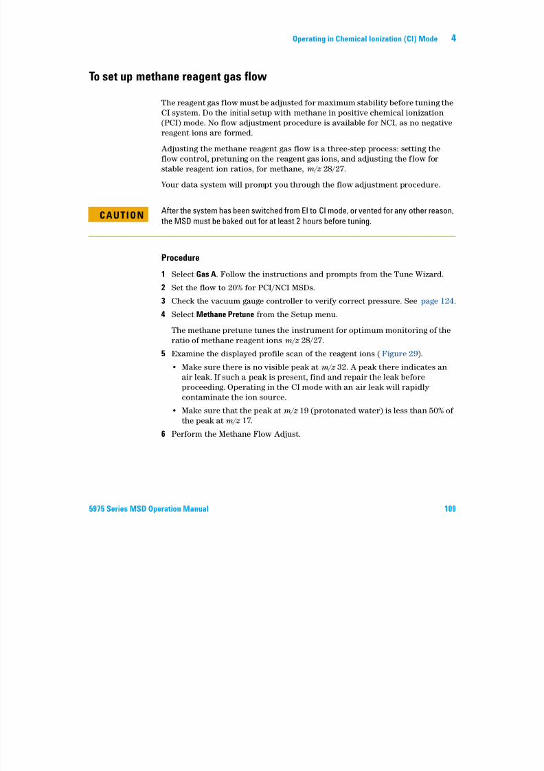
7/14/2019 Agilent 5973 MS User Manual
http://slidepdf.com/reader/full/agilent-5973-ms-user-manual 109/162
5975 Series MSD Operation Manual 109
Adjusting the methane reagent gas flow is a three-step process: setting the
flow control, pretuning on the reagent gas ions, and adjusting the flow for
stable reagent ion ratios, for methane, m/z 28/27.
Your data system will prompt you through the flow adjustment procedure.
Procedure
1 Select Gas A. Follow the instructions and prompts from the Tune Wizard.
2 Set the flow to 20% for PCI/NCI MSDs.
3 Check the vacuum gauge controller to verify correct pressure. See page 124.
4 Select Methane Pretune from the Setup menu.
The methane pretune tunes the instrument for optimum monitoring of the
ratio of methane reagent ions m/z 28/27.
5 Examine the displayed profile scan of the reagent ions (Figure 29).
• Make sure there is no visible peak at m/z 32. A peak there indicates an
air leak. If such a peak is present, find and repair the leak before
proceeding. Operating in the CI mode with an air leak will rapidly
contaminate the ion source.
• Make sure that the peak at m/z 19 (protonated water) is less than 50% of
the peak at m/z 17.
6 Perform the Methane Flow Adjust.
CAUTIONAfter the system has been switched from EI to CI mode, or vented for any other reason,
the MSD must be baked out for at least 2 hours before tuning.
4 Operating in Chemical Ionization (CI) Mode
CAUTIONContinuing with CI autotune if the MSD has an air leak or large amounts of water will
result in severe ion source contamination. If this happens, you will need to vent the
MSD and clean the ion source .
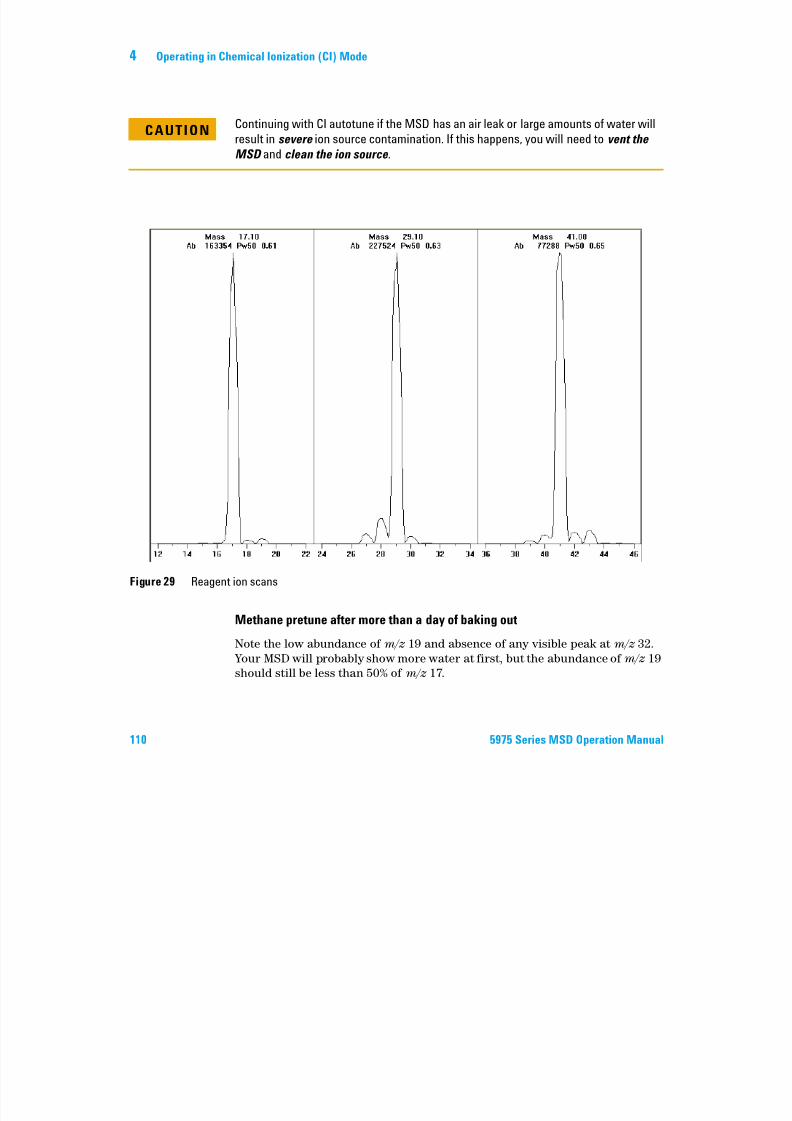
7/14/2019 Agilent 5973 MS User Manual
http://slidepdf.com/reader/full/agilent-5973-ms-user-manual 110/162
110 5975 Series MSD Operation Manual
Methane pretune after more than a day of baking out
Note the low abundance of m/z 19 and absence of any visible peak at m/z 32.
Your MSD will probably show more water at first, but the abundance of m/z 19
should still be less than 50% of m/z 17.
Figure 29 Reagent ion scans
Operating in Chemical Ionization (CI) Mode 4
To use other reagent gases
This section describes the use of isobutane or ammonia as the reagent gas. Youshould be familiar with operating the CI-equipped 5975 Series MSD with
methane reagent gas before attempting to use other reagent gases.
Do not use nitrous oxide as a reagent gas It radically shortens the life span of the
7/14/2019 Agilent 5973 MS User Manual
http://slidepdf.com/reader/full/agilent-5973-ms-user-manual 111/162
5975 Series MSD Operation Manual 111
Changing the reagent gas from methane to either isobutane or ammonia
changes the chemistry of the ionization process and yields different ions. The
principal chemical ionization reactions encountered are described in general
in Appendix A, “Chemical Ionization Theory . If you are not experienced with
chemical ionization, we suggest reviewing that material before you proceed.
CAUTIONDo not use nitrous oxide as a reagent gas. It radically shortens the life span of the
filament.
CAUTION Not all setup operations can be performed in all modes with all reagent gases. SeeTable 18 for details.
4 Operating in Chemical Ionization (CI) Mode
Table 18 Reagent gases
Reagent gas/mode Reagent ion masses PFDTDCalibrant ions
Flow adj ions: RatioEI/PCI/NCI MSD
Performance turbo
pump
Recommended flow:
20% PCI
7/14/2019 Agilent 5973 MS User Manual
http://slidepdf.com/reader/full/agilent-5973-ms-user-manual 112/162
112 5975 Series MSD Operation Manual
Isobutane CIIsobutane (C4H10) is commonly used for chemical ionization when less
fragmentation is desired in the chemical ionization spectrum. This is because
the proton affinity of isobutane is higher than that of methane; hence less
energy is transferred in the ionization reaction.
Addition and proton transfer are the ionization mechanisms most often
associated with isobutane. The sample itself influences which mechanism
dominates.
40% NCI
Methane/PCI 17, 29, 41*
* There are no PFDTD ions formed with any reagent gas but methane. Tune with methane and usethe same parameters for the other gas.
41, 267, 599 28/27: 1.5 – 5.0
Methane/NCI 17, 35, 235†
† There are no negative reagent gas ions formed. To pretune in negative mode, use backgroundions: 17 (OH-), 35 (Cl-), and 235 (ReO3-). These ions can not be used for reagent gas flow adjust-ment. Set flow to 40% for NCI and adjust as necessary to get acceptable results for your appli-cation.
185, 351, 449 N/A
Isobutane/PCI 39, 43, 57 N/A 57/43: 5.0 – 30.0
Isobutane/NCI 17, 35, 235 185, 351, 449 N/A
Ammonia/PCI 18, 35, 52 N/A 35/18: 0.1 – 1.0
Ammonia/NCI 17, 35, 235 185, 351, 517 N/A
Operating in Chemical Ionization (CI) Mode 4
Ammonia CI
Ammonia (NH3) is commonly used for chemical ionization when less
fragmentation is desired in the chemical ionization spectrum. This is becausethe proton affinity of ammonia is higher than that of methane; hence less
energy is transferred in the ionization reaction.
Because many compounds of interest have insufficient proton affinities,
ammonia chemical-ionization spectra often result from the addition of NH4+
7/14/2019 Agilent 5973 MS User Manual
http://slidepdf.com/reader/full/agilent-5973-ms-user-manual 113/162
5975 Series MSD Operation Manual 113
a o a c e ca o at o spect a o te esu t o t e add t o o N 4
and then, in some cases, from the subsequent loss of water. Ammonia reagent
ion spectra have principal ions at m/z 18, 35, and 52, corresponding to NH4+,
NH4(NH3)+, and NH4(NH3)2+.
To adjust your MSD for isobutane or ammonia chemical ionization, use the
following procedure:
Procedure
1 From the Tune and Vacuum Control view, perform a standard Positive CI
autotune with methane and PFDTD.
2 Under the Setup menu, click CI Tune Wizard and when prompted select
Isobutane or Ammonia. This will change the menus to use the selected gas and
select appropriate default tune parameters.
3 Select Gas B. Follow the instructions and prompts from the Tune Wizard
and set the gas flow to 20%.
If you use an existing tune file, be sure to save it with a new name if you
don’t want to overwrite the existing values. Accept the default temperatureand other settings.
4 Click Isobutane (or Ammonia) Flow Adjust on the Setup menu.
There is no CI autotune for isobutane or ammonia in PCI.
If you wish to run NCI with isobutane or ammonia, load NCICH4.U or an
existing NCI tune file for the specific gas.
NOTEBe sure to read the following application note: Implementation of Ammonia Reagent
Gas for Chemical Ionization on the Agilent 5975 Series MSDs (5989-5170EN).
4 Operating in Chemical Ionization (CI) Mode
CAUTIONUse of ammonia affects the maintenance requirements of the MSD. See “CI
Maintenance” for more information.
CAUTIONThe pressure of the ammonia supply must be less than 5 psig. Higher pressures can
result in ammonia condensing from a gas to a liquid.
7/14/2019 Agilent 5973 MS User Manual
http://slidepdf.com/reader/full/agilent-5973-ms-user-manual 114/162
114 5975 Series MSD Operation Manual
Ammonia tends to break down vacuum pump fluids and seals. Ammonia CI
makes more frequent vacuum system maintenance necessary. (See the 5975
Series MSD Troubleshooting and Maintenance Manual.)
Frequently, a mixture of 5% ammonia and 95% helium or 5% ammonia and 95%
methane is used as a CI reagent gas. This is enough ammonia to achieve good
chemical ionization while minimizing its negative effects.
Carbon dioxide CI
Carbon dioxide is often used as a reagent gas for CI. It has obvious advantages
of availability and safety.
Always keep the ammonia tank in an upright position, below the level of the flow
module. Coil the ammonia supply tubing into several vertical loops by wrapping the
tubing around a can or bottle. This will help keep any liquid ammonia out of the flowmodule.
CAUTIONWhen running ammonia for 5 or more hours a day, the foreline pump must be ballasted
(flushed with air) for at least 1 hour a day to minimize damage to pump seals. Always
purge the MSD with methane after flowing ammonia.
Operating in Chemical Ionization (CI) Mode 4
To switch from the CI source to the EI source
Procedure
1 From the Tune and Vacuum Control view, vent the MSD. See page 82. The
software will prompt you for the appropriate actions.
2 Open the analyzer.
3 Remo e the CI interface tip seal See page 143
7/14/2019 Agilent 5973 MS User Manual
http://slidepdf.com/reader/full/agilent-5973-ms-user-manual 115/162
5975 Series MSD Operation Manual 115
3 Remove the CI interface tip seal. See page 143.
4 Remove the CI ion source. See page 142.
5 Install the EI ion source. See page 136.
6 Place the CI ion source and interface tip seal in the ion source storage box.
7 Pump down the MSD. See page 91.
8 Load your EI tune file.
CAUTIONAlways wear clean gloves while touching the analyzer or any other parts that go inside
the analyzer chamber.
CAUTIONElectrostatic discharges to analyzer components are conducted to the side board
where they can damage sensitive components. Wear a grounded antistatic wrist strap
and take other antistatic precautions before you open the analyzer chamber.
See page 131.
4 Operating in Chemical Ionization (CI) Mode
CI Autotune
After the reagent gas flow is adjusted, the lenses and electronics of the MSDshould be tuned (Table 19). Perfluoro-5,8-dimethyl-3,6,9-trioxidodecane
(PFDTD) is used as the calibrant. Instead of flooding the entire vacuum
chamber, the PFDTD is introduced directly into the ionization chamber
through the GC/MSD interface by means of the gas flow control module.
7/14/2019 Agilent 5973 MS User Manual
http://slidepdf.com/reader/full/agilent-5973-ms-user-manual 116/162
116 5975 Series MSD Operation Manual
There is a PCI autotune for methane only, as there are no PFDTD ions
produced by other gases in positive mode. PFDTD ions are visible in NCI for
any reagent gas. Always tune for methane PCI first regardless of which mode
or reagent gas you wish to use for your analysis.
There are no tune performance criteria. If CI autotune completes, it passes.
EMVolts (electron multiplier voltage) at or above 2600 V, however, indicates a
problem. If your method requires EMVolts set at +400, you may not have
adequate sensitivity in your data acquisition.
CAUTIONAfter the source is changed from EI to CI or vented for any other reason, the MSD must
be purged and baked out for at least 2 hours before tuning. Longer bakeout isrecommended before running samples requiring optimal sensitivity.
CAUTIONAlways verify MSD performance in EI before switching to CI operation. See page 76.
Always set up the CI MSD in PCI first, even if you are going to run NCI.
Operating in Chemical Ionization (CI) Mode 4
Table 19 Reagent gas settings
Reagent gas Methane Isobutane Ammonia EI
Ion polarity Positive Negative Positive Negative Positive Negative N/A
Emission 150 A 50 A 150 A 50 A 150 A 50 A 35 A
Electron
energy
150 eV 150 eV 150 eV 150 eV 150 eV 150 eV 70 eV
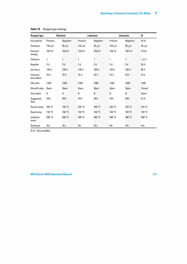
7/14/2019 Agilent 5973 MS User Manual
http://slidepdf.com/reader/full/agilent-5973-ms-user-manual 117/162
5975 Series MSD Operation Manual 117
energy
Filament 1 1 1 1 1 1 1 or 2
Repeller 3 V 3 V 3 V 3 V 3 V 3 V 30 V
Ion focus 130 V 130 V 130 V 130 V 130 V 130 V 90 V
Entrance
lens offset
20 V 20 V 20 V 20 V 20 V 20 V 25 V
EM volts 1200 1400 1200 1400 1200 1400 1300
Shutoff valve Open Open Open Open Open Open Closed
Gas select A A B B B B None
Suggested
flow
20% 40% 20% 40% 20% 40% N/A
Source temp 250 °C 150 °C 250 °C 150 °C 250 °C 150 °C 230 °C
Quad temp 150 °C 150 °C 150 °C 150 °C 150 °C 150 °C 150 °C
Interfacetemp
280 °C 280 °C 280 °C 280 °C 280 °C 280 °C 280 °C
Autotune Yes Yes No Yes No Yes Yes
N/A Not available
4 Operating in Chemical Ionization (CI) Mode
To perform a PCI autotune (methane only)
Procedure
CAUTIONAlways verify MSD performance in EI before switching to CI operation. See page 76.
Always set up the CI MSD in PCI first, even if you are going to run NCI.
7/14/2019 Agilent 5973 MS User Manual
http://slidepdf.com/reader/full/agilent-5973-ms-user-manual 118/162
118 5975 Series MSD Operation Manual
Procedure
1 Verify that the MSD performs correctly in EI mode first. See page 76.
2 Load the PCICH4.U tune file (or an existing tune file for the reagent gas you
are using).
If you use an existing tune file, be sure to save it with a new name if you
don’t want to overwrite the existing values.
3 Accept the default settings.
4 Perform methane setup. See page 109.
5 Under the Tune menu, click CI Autotune.
There are no tune performance criteria. If autotune completes, it passes(Figure 30). If the tune sets the electron multiplier voltage (EMVolts) at or
above 2600 V, however, you may not be able to acquire data successfully if your
method sets EMVolts to “+400” or higher.
The autotune report contains information about air and water in the system.
The 19/29 ratio shows the abundance of water.
The 32/29 ratio shows the abundance of oxygen.
CAUTIONAvoid tuning more often than is absolutely necessary; this will minimize PFDTD
background noise and help prevent ion source contamination.
Operating in Chemical Ionization (CI) Mode 4
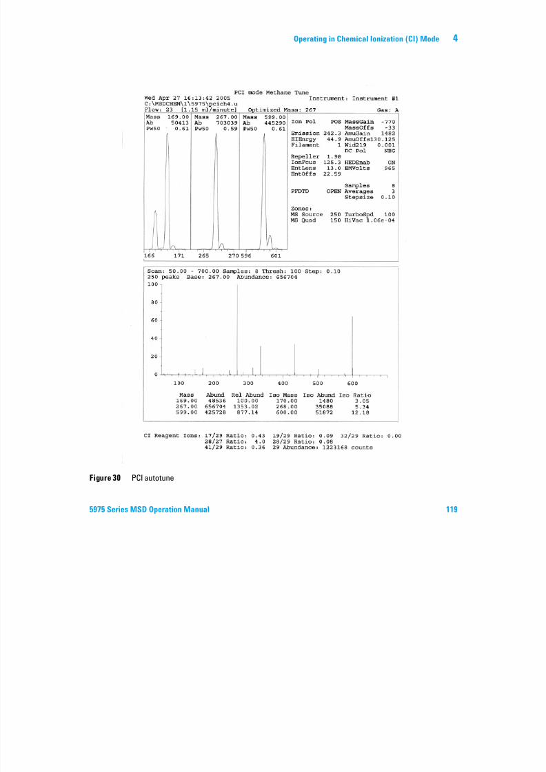
7/14/2019 Agilent 5973 MS User Manual
http://slidepdf.com/reader/full/agilent-5973-ms-user-manual 119/162
5975 Series MSD Operation Manual 119
Figure 30 PCI autotune
4 Operating in Chemical Ionization (CI) Mode
To perform an NCI autotune (methane reagent gas)
P d
CAUTIONAlways verify MSD performance in EI before switching to CI operation. See page 76.
Always set up the CI MSD in PCI with methane as the reagent gas first, even if you are
going to be using a different reagent gas or going to run NCI.
7/14/2019 Agilent 5973 MS User Manual
http://slidepdf.com/reader/full/agilent-5973-ms-user-manual 120/162
120 5975 Series MSD Operation Manual
Procedure
1 From the Tune and Vacuum Control view, load NCICH4.U (or an existing tunefile for the reagent gas you are using).
2 From the Setup menu select the CI Tune Wizard and follow the system
prompts.
Accept the default temperature and other settings.
If you use an existing tune file, be sure to save it with a new name if you
don’t want to overwrite the existing values.
3 Under the Tune menu, click CI Autotune.
There are no tune performance criteria. If autotune completes, it passes(Figure 31). If the tune sets the electron multiplier voltage (EMVolts) at or
above 2600 V, however, you may not be able to acquire data successfully if your
method sets EMVolts to “+400” or higher.
CAUTIONAvoid tuning unless absolutely necessary; this will minimize PFDTD background noise
and help prevent ion source contamination.
Operating in Chemical Ionization (CI) Mode 4
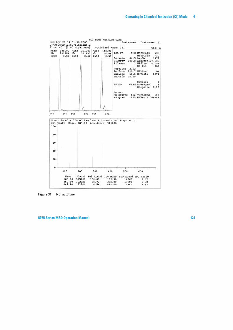
7/14/2019 Agilent 5973 MS User Manual
http://slidepdf.com/reader/full/agilent-5973-ms-user-manual 121/162
5975 Series MSD Operation Manual 121
Figure 31 NCI autotune
4 Operating in Chemical Ionization (CI) Mode
To verify PCI performance
Materials needed
• Benzophenone, 100 pg/L (8500-5440)
CAUTIONAlways verify MSD performance in EI before switching to CI operation. See page 76.
Always set up the CI MSD in PCI first, even if you are going to run NCI.
7/14/2019 Agilent 5973 MS User Manual
http://slidepdf.com/reader/full/agilent-5973-ms-user-manual 122/162
122 5975 Series MSD Operation Manual
Procedure
1 Verify that the MSD performs correctly in E1 mode.
2 Verify that the PCICH4.U tune file is loaded.
3 Select Gas A and set flow to 20%.
4 In Tune and Vacuum Control view, perform CI setup. See page 116.
5 Run CI Autotune. See page 116.
6 Run the PCI sensitivity method BENZ_PCI.M using 1 µL of 100 pg/µL
benzophenone.
7 Verify that the system conforms to the published sensitivity specification.
Please see the Agilent Web site at www.agilent.com/chem for specifications.
Operating in Chemical Ionization (CI) Mode 4
To verify NCI performance
This procedure is for EI/PCI/NCI MSDs only.
Materials needed
• Octafluoronaphthalene (OFN), 100 fg/µL (5188-5347)
Always verify MSD performance in EI before switching to CI operation See page 76
7/14/2019 Agilent 5973 MS User Manual
http://slidepdf.com/reader/full/agilent-5973-ms-user-manual 123/162
5975 Series MSD Operation Manual 123
Procedure
1 Verify that the MSD performs correctly in EI mode.
2 Load the NCICH4.U tune file, and accept the temperature setpoints.
3 Select Gas A and set flow to 40%.
4 In Tune and Vacuum Control view, run CI Autotune. See page 120.
Note that there are no criteria for a “passing” Autotune in CI. If the
Autotune completes, it passes.
5 Run the NCI sensitivity method: OFN_NCI.M using 2 µL of 100 fg/µL OFN.
6 Verify that the system conforms to the published sensitivity specification.
Please see the Agilent Web site at www.agilent.com/chem for specifications.
CAUTIONAlways verify MSD performance in EI before switching to CI operation. See page 76.
Always set up the CI MSD in PCI first, even if you are going to run NCI.
4 Operating in Chemical Ionization (CI) Mode
To monitor high vacuum pressure
Procedure
WARNINGIf you are using hydrogen as a carrier gas, do not turn on the Micro-Ion vacuum
gauge if there is any possibility that hydrogen has accumulated in the manifold.
Read “Hydrogen Safety” before operating the MSD with hydrogen carrier gas.
7/14/2019 Agilent 5973 MS User Manual
http://slidepdf.com/reader/full/agilent-5973-ms-user-manual 124/162
124 5975 Series MSD Operation Manual
Procedure
1 Start up and pump down the MSD. See page 103.2 In the Tune and Vacuum Control view select Turn Vacuum Gauge on/off from
the Vacuum menu.
3 In the Instrument Control view you can set up an MS Monitor for reading.
The vacuum can also be read on the LCP or from the Manual Tune screen.
The gauge controller will not turn on if the pressure in the MSD is above
approximately 8 × 10⁻³ Torr. The gauge controller is calibrated for nitrogen, but
all pressures listed in this manual are for helium.
The largest influence on operating pressure is the carrier gas (column) flow.
Table 20 lists typical pressures for various helium carrier gas flows. These
pressures are approximate and will vary from instrument to instrument.
Operating in Chemical Ionization (CI) Mode 4
Typical pressure readings
Use the G3397A Micro-Ion vacuum gauge. Note that the mass flow controller is
calibrated for methane and the vacuum gauge is calibrated for nitrogen, sothese measurements are not accurate, but are intended as a guide to typical
observed readings (Table 20). They were taken with the following set of
conditions. Note that these are typical PCI temperatures:
Source temperature 250 °CQuad temperature 150 °CI f 280 °C

7/14/2019 Agilent 5973 MS User Manual
http://slidepdf.com/reader/full/agilent-5973-ms-user-manual 125/162
5975 Series MSD Operation Manual 125
Familiarize yourself with the measurements on your system under operating
conditions and watch for changes that may indicate a vacuum or gas f low
problem. Measurements will vary by as much as 30% from one MSD and gauge
controller to the next.
Interface temperature 280 °CHelium carrier gas flow 1 mL/min
Table 20 Flow and pressure readings
Pressure (Torr)
Methane Ammonia
MFC(%)
EI/PCI/NCI MSD(Performance turbo pump)
EI/PCI/NCI MSD(Performance turbo pump)
10 5.5 ×10 –5 5.0 ×10 –5
15 8.0 ×10 –5 7.0 ×10 –5
20 1.0 ×10 –4 8.5 ×10 –5
25 1.2 ×10 –4 1.0 ×10 –4
30 1.5 ×1 –4 1.2 ×10 –4
35 2.0 ×10 –4 1.5 ×10 –4
40 2.5 ×10 –4 2.0 ×10 –4
4 Operating in Chemical Ionization (CI) Mode

7/14/2019 Agilent 5973 MS User Manual
http://slidepdf.com/reader/full/agilent-5973-ms-user-manual 126/162
126 5975 Series MSD Operation Manual
Agilent 5975 Series MSD
Operation Manual
5
General Maintenance
Before Starting 128
Maintaining the Vacuum System 133
7/14/2019 Agilent 5973 MS User Manual
http://slidepdf.com/reader/full/agilent-5973-ms-user-manual 127/162
127Agilent Technologies
5 General Maintenance
Before Starting
You can perform much of the maintenance required by your MSD. For yoursafety, read all of the information in this introduction before performing any
maintenance tasks.
Scheduled maintenance
Common maintenance tasks are listed in Table 21. Performing these tasks
when scheduled can reduce operating problems, prolong system life, and
d ll ti t
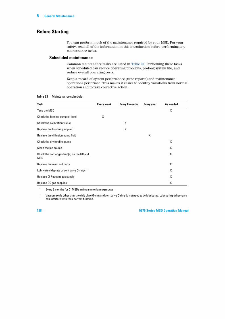
7/14/2019 Agilent 5973 MS User Manual
http://slidepdf.com/reader/full/agilent-5973-ms-user-manual 128/162
128 5975 Series MSD Operation Manual
reduce overall operating costs.
Keep a record of system performance (tune reports) and maintenance
operations performed. This makes it easier to identify variations from normal
operation and to take corrective action.
Table 21 Maintenance schedule
Task Every week Every 6 months Every year As needed
Tune the MSD X
Check the foreline pump oil level X
Check the calibration vial(s) X
Replace the foreline pump oil* X
Replace the diffusion pump fluid X
Check the dry foreline pump X
Clean the ion source X
Check the carrier gas trap(s) on the GC and
MSD
X
Replace the worn out parts X
Lubricate sideplate or vent valve O-rings† X
Replace CI Reagent gas supply X
Replace GC gas supplies X
* Every 3 months for CI MSDs using ammonia reagent gas.
† Vacuum seals other than the side plate O-ring and vent valve O-ring do not need to be lubricated. Lubricating other sealscan interfere with their correct function.
General Maintenance 5
Tools, spare parts, and supplies
Some of the required tools, spare parts, and supplies are included in the GC
shipping kit, MSD shipping kit, or MSD tool kit. You must supply others yourself. Each maintenance procedure includes a list of the materials required
for that procedure.
High voltage precautions
Whenever the MSD is plugged in, even if the power switch is off, potentially
dangerous voltage (120 VAC or 200/240 VAC) exists on:
7/14/2019 Agilent 5973 MS User Manual
http://slidepdf.com/reader/full/agilent-5973-ms-user-manual 129/162
5975 Series MSD Operation Manual 129
dangerous voltage (120 VAC or 200/240 VAC) exists on:
• The wiring and fuses between where the power cord enters the instrument
and the power switch
When the power switch is on, potentially dangerous voltages exist on:
• Electronic circuit boards
• Toroidal transformer
• Wires and cables between these boards
• Wires and cables between these boards and the connectors on the back
panel of the MSD
• Some connectors on the back panel (for example, the foreline power
receptacle)
Normally, all of these parts are shielded by safety covers. As long as the safety
covers are in place, it should be difficult to accidentally make contact with
dangerous voltages.
Some procedures in this chapter require access to the inside of the MSD while
the power switch is on. Do not remove any of the electronics safety covers inany of these procedures. To reduce the risk of electric shock, follow the
procedures carefully.
WARNINGPerform no maintenance with the MSD turned on or plugged into its power source
unless you are instructed to by one of the procedures in this chapter.
5 General Maintenance
Dangerous temperatures
Many parts in the MSD operate at, or reach, temperatures high enough to
cause serious burns. These parts include, but are not limited to:• GC/MSD interface
• Analyzer parts
• Vacuum pumps
WARNINGNever touch these parts while your MSD is on. After the MSD is turned off, give

7/14/2019 Agilent 5973 MS User Manual
http://slidepdf.com/reader/full/agilent-5973-ms-user-manual 130/162
130 5975 Series MSD Operation Manual
The GC inlets and GC oven also operate at very high temperatures. Use the
same caution around these parts. See the documentation supplied with your
GC for more information.
Chemical residue
Only a small portion of your sample is ionized by the ion source. The majority
of any sample passes through the ion source without being ionized. It is
pumped away by the vacuum system. As a result, the exhaust from the forelinepump will contain traces of the carrier gas and your samples. Exhaust from
the standard foreline pump also contains tiny droplets of foreline pump oil.
An oil trap is supplied with the standard foreline pump. This trap stops only
pump oil droplets. It does not trap any other chemicals. If you are using toxic
solvents or analyzing toxic chemicals, do not use this oil trap. For all foreline
WARNING
these parts enough time to cool before handling them.
WARNINGThe GC/MSD interface heater is powered by a thermal zone on the GC. The interface
heater can be on, and at a dangerously high temperature, even though the MSD is
off. The GC/MSD interface is well insulated. Even after it is turned off, it cools very
slowly.
WARNINGThe foreline pump can cause burns if touched when operating. It has a safety shield
to prevent the user from touching it.
General Maintenance 5
pumps, install a hose to take the exhaust from the foreline pump outdoors or
into a fume hood vented to the outdoors. For the standard foreline pump, this
requires removing the oil trap. Be sure to comply with your local air quality
regulations.
WARNINGThe oil trap supplied with the standard foreline pump stops only foreline pump oil. It
does not trap or filter out toxic chemicals. If you are using toxic solvents or
analyzing toxic chemicals, remove the oil trap. Do not use the trap if you have a CI
MSD. Install a hose to take the foreline pump exhaust outside or to a fume hood.

7/14/2019 Agilent 5973 MS User Manual
http://slidepdf.com/reader/full/agilent-5973-ms-user-manual 131/162
5975 Series MSD Operation Manual 131
The fluids in the diffusion pump and standard foreline pump also collect
traces of the samples being analyzed. All used pump fluid should be
considered hazardous and handled accordingly. Dispose of used fluid
correctly, as specified by your local regulations.
Electrostatic discharge
All of the printed circuit boards in the MSD contain components that can be
damaged by electrostatic discharge (ESD). Do not handle or touch these
boards unless absolutely necessary. In addition, wires, contacts, and cables
can conduct ESD to the electronics boards to which they are connected. This is
especially true of the mass filter (quadrupole) contact wires which can carry
ESD to sensitive components on the side board. ESD damage may not cause
immediate failure but it will gradually degrade the performance and stability
of your MSD.
When you work on or near printed circuit boards or when you work on
components with wires, contacts, or cables connected to printed circuit
boards, always use a grounded antistatic wrist strap and take other antistaticprecautions. The wrist strap should be connected to a known good earth
ground. If that is not possible, it should be connected to a conductive (metal)
part of the assembly being worked on, but not to electronic components,
exposed wires or traces, or pins on connectors.
WARNINGWhen replacing pump fluid, use appropriate chemical-resistant gloves and safety
glasses. Avoid all contact with the fluid.
5 General Maintenance
Take extra precautions, such as a grounded antistatic mat, if you must work
on components or assemblies that have been removed from the MSD. This
includes the analyzer.
CAUTIONTo be effective, an antistatic wrist strap must fit snugly (not tight). A loose strap
provides little or no protection.
Antistatic precautions are not 100% effective. Handle electronic circuit boards as little
as possible and then only by the edges. Never touch components, exposed traces, or
pins on connectors and cables.
7/14/2019 Agilent 5973 MS User Manual
http://slidepdf.com/reader/full/agilent-5973-ms-user-manual 132/162
132 5975 Series MSD Operation Manual
General Maintenance 5
Maintaining the Vacuum System
Periodic maintenance As listed earlier in Table 21, some maintenance tasks for the vacuum system
must be performed periodically. These include:
• Checking the foreline pump fluid (every week)
• Checking the calibration vial(s) (every 6 months)
• Ballasting the foreline pump (daily in MSDs using ammonia reagent gas)
7/14/2019 Agilent 5973 MS User Manual
http://slidepdf.com/reader/full/agilent-5973-ms-user-manual 133/162
5975 Series MSD Operation Manual 133
• Replacing the foreline pump oil (every 6 months; every 3 months for CIMSDs using ammonia reagent gas)
• Tightening the foreline pump oil box screws (first oil change after
installation)
• Replacing the diffusion pump fluid (once a year)
• Replacing the dry foreline pump (typically every 3 years)
Failure to perform these tasks as scheduled can result in decreasedinstrument performance. It can also result in damage to your instrument.
Other procedures
Tasks such as replacing a foreline vacuum gauge or Micro-Ion vacuum gauge
should be performed only when needed. See the 5975 Series MSD
Troubleshooting and Maintenance manual and see the online help in the MSD
ChemStation software for symptoms that indicate this type of maintenance isrequired.
More information is available
If you need more information about the locations or functions of vacuum
system components, see the 5975 Series MSD Troubleshooting and
Maintenance manual.
Most of the procedures in this chapter are illustrated with video clips on the
Agilent GC/GCMSD Hardware User Information & Instrument Utilities and
5975 Series MSD User Information disks.
5 General Maintenance
To remove the EI ion source
Materials needed
• Gloves, clean, lint-free
• Large (8650-0030)
• Small (8650-0029)
• Pliers, long-nose (8710-1094)
Procedure
7/14/2019 Agilent 5973 MS User Manual
http://slidepdf.com/reader/full/agilent-5973-ms-user-manual 134/162
134 5975 Series MSD Operation Manual
1 Vent the MSD. See page 82.
2 Open the analyzer chamber. See page 84.
Make sure you use an antistatic wrist strap and take other antistatic
precautions before touching analyzer components.
3 Disconnect the seven wires from the ion source. Do not bend the wires any
more than necessary (Figure 32 and Table 22).
Table 22 Ion source wires
Wire color Connects to Number of leads
Blue Entrance lens 1
Orange Ion focus 1
White Filament 1 (top
filament)
2
Red Repeller 1
Black Filament 2 (bottom
filament)
2
CAUTIONPull on the connectors, not on the wires.
General Maintenance 5
4 Trace the wires for the ion source heater and temperature sensor to the
feedthrough board. Disconnect them there.
5 Remove the thumbscrews that hold the ion source in place.
6 Pull the ion source out of the source radiator.
WARNINGThe analyzer operates at high temperatures. Do not touch any part until you are sure
it is cool.
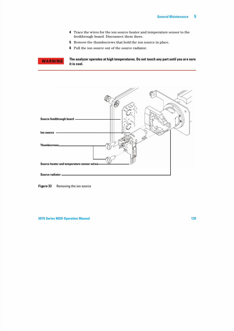
7/14/2019 Agilent 5973 MS User Manual
http://slidepdf.com/reader/full/agilent-5973-ms-user-manual 135/162
5975 Series MSD Operation Manual 135
Figure 32 Removing the ion source
Source feedthrough board
Ion source
Thumbscrews
Source heater and temperature sensor wires
Source radiator
5 General Maintenance
To reinstall the EI ion source
Materials needed
• Gloves, clean, lint-free
• Large (8650-0030)
• Small (8650-0029)
• Pliers, long-nose (8710-1094)
Procedure
7/14/2019 Agilent 5973 MS User Manual
http://slidepdf.com/reader/full/agilent-5973-ms-user-manual 136/162
136 5975 Series MSD Operation Manual
1 Slide the ion source into the source radiator (Figure 33).
2 Install and hand tighten the source thumbscrews. Do not overtighten the
thumbscrews.
3 Connect the ion source wires as shown in “To close the analyzer chamber” .
Close the analyzer chamber.
General Maintenance 5
4 Pump down the MSD. See page 91.
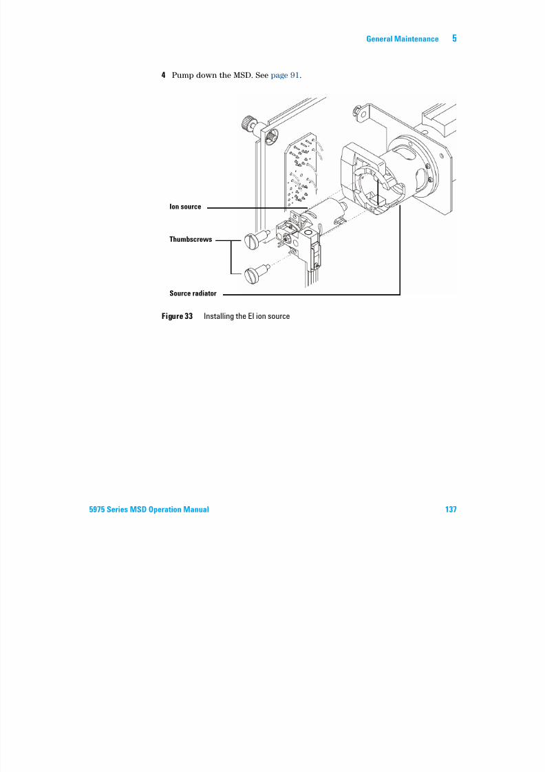
7/14/2019 Agilent 5973 MS User Manual
http://slidepdf.com/reader/full/agilent-5973-ms-user-manual 137/162
5975 Series MSD Operation Manual 137
Figure 33 Installing the EI ion source
Ion source
Thumbscrews
Source radiator
5 General Maintenance

7/14/2019 Agilent 5973 MS User Manual
http://slidepdf.com/reader/full/agilent-5973-ms-user-manual 138/162
138 5975 Series MSD Operation Manual
Agilent 5975 Series MSD
Operation Manual
6
CI Maintenance
General Information 140
Ion source cleaning 140
Ammonia 140
To Set Up Your MSD for CI Operation 141
G id li 141
7/14/2019 Agilent 5973 MS User Manual
http://slidepdf.com/reader/full/agilent-5973-ms-user-manual 139/162
139Agilent Technologies
Guidelines 141To install the CI ion source 142
To install the CI interface tip seal 143
This chapter describes maintenance procedures and requirements that are
unique to 5975 Series MSDs equipped with the Chemical Ionization hardware.
6 CI Maintenance
General Information
Ion source cleaningThe main effect of operating the MSD in CI mode is the need for more frequent
ion source cleaning. In CI operation, the ion source chamber is subject to more
rapid contamination than in EI operation because of the higher source
pressures required for CI.
WARNING
Always perform any maintenance procedures using hazardous solvents under a
fume hood Be sure to operate the MSD in a well ventilated room

7/14/2019 Agilent 5973 MS User Manual
http://slidepdf.com/reader/full/agilent-5973-ms-user-manual 140/162
140 5975 Series MSD Operation Manual
Ammonia
Ammonia, used as a reagent gas, increases the need for foreline pump
maintenance. Ammonia causes foreline pump oil to break down more quickly.
Therefore, the oil in the standard foreline vacuum pump must be checked andreplaced more frequently.
Always purge the MSD with methane after using ammonia.
Be sure to install the ammonia so the tank is in an upright position. This will
help prevent liquid ammonia from getting into the flow module.
WARNING fume hood. Be sure to operate the MSD in a well-ventilated room.
CI Maintenance 6
To Set Up Your MSD for CI Operation
Setting up your MSD for operation in CI mode requires special care to avoid
contamination and air leaks.
Guidelines
• Before venting in EI mode, verify that the GC/MSD system is performing
correctly. See “To verify system performance” .
• Make sure the reagent gas inlet line(s) are equipped with gas purifiers (not
applicable for ammonia)
7/14/2019 Agilent 5973 MS User Manual
http://slidepdf.com/reader/full/agilent-5973-ms-user-manual 141/162
5975 Series MSD Operation Manual 141
applicable for ammonia).
• Use extra-high purity reagent gases; 99.99% or better for methane and as
pure as is available for other reagent gases.
6 CI Maintenance
To install the CI ion source
Procedure
1 Vent the MSD and open the analyzer. See page 84.
2 Remove the EI ion source See page 134
CAUTION Electrostatic discharges to analyzer components are conducted to the side boardwhere they can damage sensitive components. Wear a grounded antistatic wrist strap
and take other antistatic precautions before you open the analyzer chamber.

7/14/2019 Agilent 5973 MS User Manual
http://slidepdf.com/reader/full/agilent-5973-ms-user-manual 142/162
142 5975 Series MSD Operation Manual
2 Remove the EI ion source. See page 134.3 Remove the CI ion source from its storage box and insert the ion source into
the radiator.
4 Reinstall the thumbscrews (Figure 34).
5 Connect the wiring as described in “To close the analyzer chamber” .
Figure 34 Installing the CI ion source
Ion source
Thumbscrews
Source radiator
CI Maintenance 6
To install the CI interface tip seal
Materials needed
• Interface tip seal (G1099-60412)
The interface tip seal must be in place for CI operation. It is necessary to
achieve adequate ion source pressure for CI.
CAUTIONElectrostatic discharges to analyzer components are conducted to the side board
where they can damage sensitive components. Wear a grounded antistatic wrist strap
and take other antistatic precautions before you open the analyzer chamber.
7/14/2019 Agilent 5973 MS User Manual
http://slidepdf.com/reader/full/agilent-5973-ms-user-manual 143/162
5975 Series MSD Operation Manual 143
Procedure
1 Remove the seal from the ion source storage box.
2 Verify that the CI ion source is installed.
3 Place the seal over the end of the interface. To remove the seal, reverse theabove steps.
4 Gently check the alignment of the analyzer and the interface.
When the analyzer is aligned correctly, the analyzer can be closed all the
way with no resistance except the spring tension from the interface tip seal.
5 You can align the analyzer and interface by wiggling the side plate on its
hinge. If the analyzer still will not close, contact your Agilent Technologies
service representative.
a d ta e ot e a t stat c p ecaut o s you ope t e a a y e c a be
CAUTION
Forcing the analyzer closed if these parts are misaligned will damage the seal or the
interface or the ion source, or will keep the sideplate from sealing.
6 CI Maintenance

7/14/2019 Agilent 5973 MS User Manual
http://slidepdf.com/reader/full/agilent-5973-ms-user-manual 144/162
144 5975 Series MSD Operation Manual
Agilent 5975 Series MSD
Operation Manual
A
Chemical Ionization Theory
Chemical Ionization Overview 146
Positive CI Theory 148
Negative CI Theory 155
7/14/2019 Agilent 5973 MS User Manual
http://slidepdf.com/reader/full/agilent-5973-ms-user-manual 145/162
145Agilent Technologies
A Chemical Ionization Theory
Chemical Ionization Overview
Chemical ionization (CI) is a technique for creating ions used in mass
spectrometric analyses. There are significant differences between CI and
electron ionization (EI). This section describes the most common chemical
ionization mechanisms.
In EI, relatively high-energy electrons (70 eV) collide with molecules of the
sample to be analyzed. These collisions produce (primarily) positive ions.
Upon ionization, the molecules of a given substance fragment in fairly
predictable patterns. EI is a direct process; energy is transferred by collision
from electrons to the sample molecules.

7/14/2019 Agilent 5973 MS User Manual
http://slidepdf.com/reader/full/agilent-5973-ms-user-manual 146/162
146 5975 Series MSD Operation Manual
For CI, in addition to the sample and carrier gas, large amounts of reagent gas
are introduced into the ionization chamber. Since there is so much more
reagent gas than sample, most of the emitted electrons collide with reagent gas
molecules, forming reagent ions. These reagent-gas ions react with each other
in primary and secondary reaction processes that establish an equilibrium.
They also react in various ways with sample molecules to form sample ions. CI
ion formation involves much lower energy and is much more “gentle” thanelectron ionization. Since CI results in much less fragmentation, CI spectra
usually show high abundance of the molecular ion. For this reason, CI is often
used to determine the molecular weights of sample compounds.
Methane is the most common CI reagent gas. It yields certain characteristic
ionization patterns. Other reagent gases yield different patterns and may
result in better sensitivity for some samples. Common alternative reagent
gases are isobutane and ammonia. Carbon dioxide is often used in negative CI.
Less common reagent gases are carbon dioxide, hydrogen, Freon,
trimethylsilane, nitric oxide, and methylamine. Different ionization reactions
occur with each reagent gas.
Water contamination in reagent gases will decrease CI sensitivity
dramatically. A large peak at m/z 19 (H30+) in positive CI is a diagnostic
symptom of water contamination. In high enough concentrations, especially
when combined with calibrant, water contamination will result in a heavily
WARNINGAmmonia is toxic and corrosive. Use of ammonia requires special maintenance and
safety precautions.
Chemical Ionization Theory A
contaminated ion source. Water contamination is most common immediately
after new reagent gas tubing or reagent gas cylinders are connected. This
contamination will often decrease if the reagent gas is allowed to flow for a
few hours, purging the system.
References on chemical ionization
A. G. Harrison, Chemical Ionization Mass Spectrometry, 2nd Edition, CRC
Press, INC. Boca Raton, FL (1992) ISBN 0-8493-4254-6.
W. B. Knighton, L. J. Sears, E. P. Grimsrud, “High Pressure Electron Capture
Mass Spectrometry”, Mass Spectrometry Reviews (1996), 14, 327-343.
E A Stemmler R A Hites Electron Capture Negative Ion Mass Spectra of
7/14/2019 Agilent 5973 MS User Manual
http://slidepdf.com/reader/full/agilent-5973-ms-user-manual 147/162
5975 Series MSD Operation Manual 147
E. A. Stemmler, R. A. Hites, Electron Capture Negative Ion Mass Spectra of
Environmental Contaminants and Related Compounds, VCH Publishers,
New York, NY (1988) ISBN 0-89573-708-6.
A Chemical Ionization Theory
Positive CI Theory
Positive CI (PCI) occurs with the same analyzer voltage polarities as EI. For
PCI, the reagent gas is ionized by collision with emitted electrons. The reagent
gas ions react chemically with sample molecules (as proton donors) to form
sample ions. PCI ion formation is more “gentle” than electron ionization,
producing less fragmentation. This reaction usually yields high abundance of
the molecular ion and is therefore often used for determining molecular
weights of samples.
The most common reagent gas is methane. Methane PCI produces ions with
almost any sample molecule. Other reagent gases, such as isobutane orammonia are more selective and cause even less fragmentation Because of
7/14/2019 Agilent 5973 MS User Manual
http://slidepdf.com/reader/full/agilent-5973-ms-user-manual 148/162
148 5975 Series MSD Operation Manual
ammonia, are more selective and cause even less fragmentation. Because of
the high background from the reagent gas ions, PCI is not especially sensitive
and detection limits are generally high.
There are four fundamental ionization processes that take place during
positive chemical ionization at ion source pressures in the 0.8 to 2.0 Torr
range. These are:
• Proton transfer
• Hydride abstraction
• Addition
• Charge exchange
Depending on the reagent gas used, one or more of these four processes can be
used to explain the ionization products observed in the resulting mass spectra.
EI, methane PCI, and ammonia PCI spectra of methyl stearate are shown in
Figure 35. The simple fragmentation pattern, large abundance of the [MH]+
ion, and the presence of the two adduct ions are characteristic of positive
chemical ionization using methane as a reagent gas.
The presence of air or water in the system, especially in the presence of
PFDTD calibrant, quickly contaminates the ion source.
Chemical Ionization Theory A
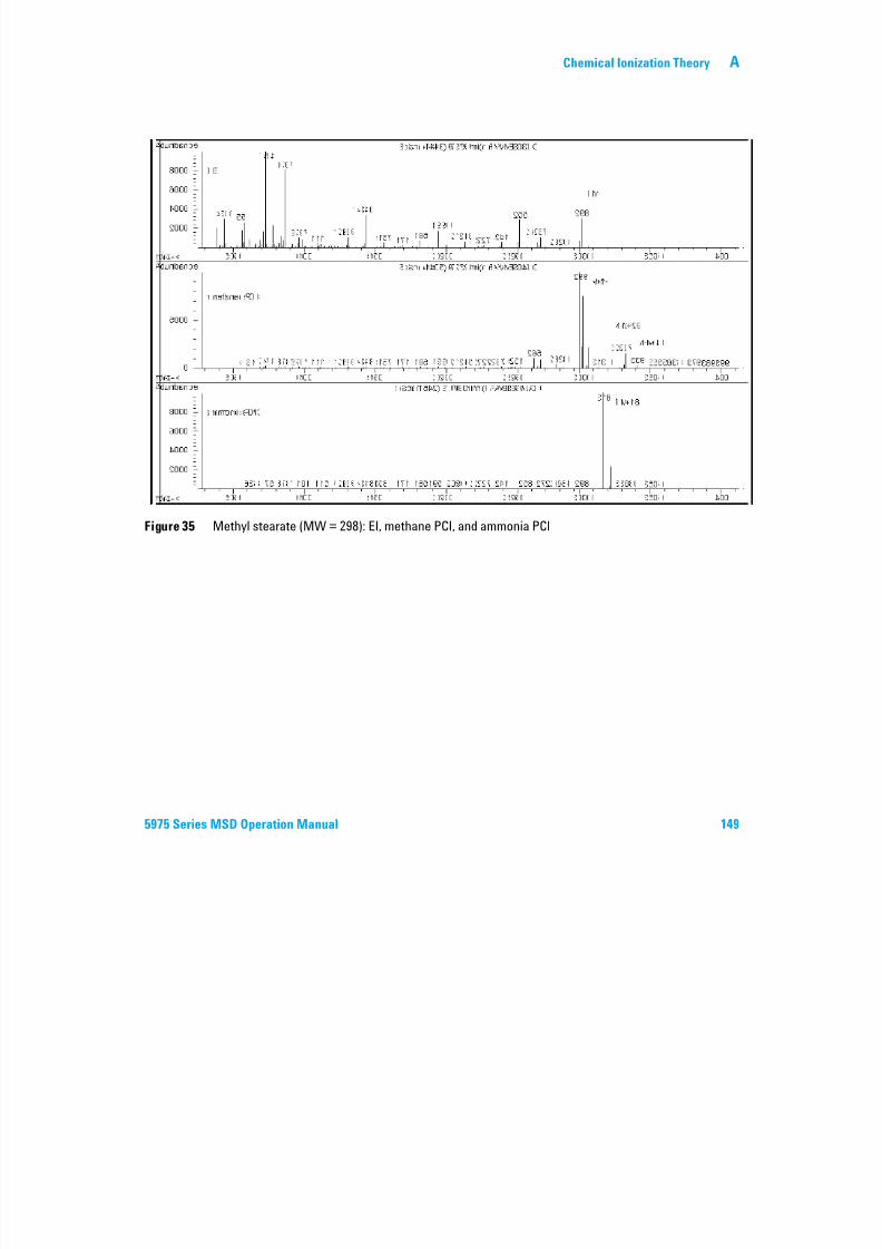
7/14/2019 Agilent 5973 MS User Manual
http://slidepdf.com/reader/full/agilent-5973-ms-user-manual 149/162
5975 Series MSD Operation Manual 149
Figure 35 Methyl stearate (MW = 298): EI, methane PCI, and ammonia PCI
A Chemical Ionization Theory
Proton transfer
Proton transfer can be expressed as
BH+ + M MH+ + B
where the reagent gas B has undergone ionization resulting in protonation. If
the proton affinity of the analyte (sample) M is greater than that of the reagent
gas, then the protonated reagent gas will transfer its proton to the analyte
forming a positively charged analyte ion.
The most frequently used example is the proton transfer from CH5+ to the
molecular analyte, which results in the protonated molecular ion MH+.
The relative proton affinities of the reagent gas and the analyte govern the

7/14/2019 Agilent 5973 MS User Manual
http://slidepdf.com/reader/full/agilent-5973-ms-user-manual 150/162
150 5975 Series MSD Operation Manual
proton transfer reaction. If the analyte has a greater proton affinity than the
reagent gas, then proton transfer can take place. Methane (CH4) is the most
common reagent gas because its proton affinity is very low.
Proton affinities can be defined according to the reaction:
B + H+ BH+
where the proton affinities are expressed in kcal/mole. Methane's proton
affinity is 127 kcal/mole. Tables 23 and 24 list the proton affinities of several
possible reagent gases and of several small organic compounds with various
functional groups.
The mass spectrum generated by a proton-transfer reaction depends on
several criteria. If the difference in proton affinities is large (as with methane),
substantial excess energy may be present in the protonated molecular ion.
This can result in subsequent fragmentation. For this reason, isobutane with a
proton affinity of 195 kcal/mole may be preferred to methane for some
analyses. Ammonia has a proton affinity of 207 kcal/mole, making it less likely
to protonate most analytes. Proton-transfer chemical ionization is usually
considered to be “soft” ionization, but the degree of the softness depends on
the proton affinities of both the analyte and the reagent gas, as well as on
other factors including ion source temperature.
Chemical Ionization Theory A
Table 23 Reagent gas proton affinities
Species Proton affinity
kcal/mole
Reactant ion
formed
H2 100 H3+ (m/z 3)
CH4 127 CH5+ (m/z 17)
C2H4 160 C2H5+ (m/z 29)
H2O 165 H3O+ (m/z 19)
H2S 170 H3S+ (m/z 35)
CH3OH 182 CH3OH2+ (m/z 33)
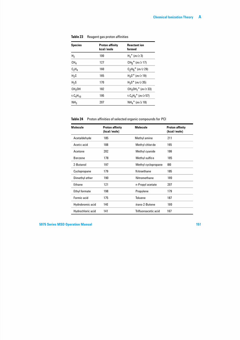
7/14/2019 Agilent 5973 MS User Manual
http://slidepdf.com/reader/full/agilent-5973-ms-user-manual 151/162
5975 Series MSD Operation Manual 151
CH3OH 182 CH3OH2 (m/z 33)
t-C4H10 195 t-C4H9+ (m/z 57)
NH3 207 NH4+ (m/z 18)
Table 24 Proton affinities of selected organic compounds for PCI
Molecule Proton affinity
(kcal/mole)
Molecule Proton affinity
(kcal/mole)
Acetaldehyde 185 Methyl amine 211
Acetic acid 188 Methyl chloride 165
Acetone 202 Methyl cyanide 186Benzene 178 Methyl sulfide 185
2-Butanol 197 Methyl cyclopropane l80
Cyclopropane 179 Nitroethane 185
Dimethyl ether 190 Nitromethane 180
Ethane 121 n-Propyl acetate 207
Ethyl formate 198 Propylene 179
Formic acid 175 Toluene 187
Hydrobromic acid 140 trans-2-Butene 180
Hydrochloric acid 141 Trifluoroacetic acid 167
A Chemical Ionization Theory
Isopropyl alcohol 190 Xylene 187
Methanol 182
Table 24 Proton affinities of selected organic compounds for PCI (continued)
Molecule Proton affinity
(kcal/mole)
Molecule Proton affinity
(kcal/mole)
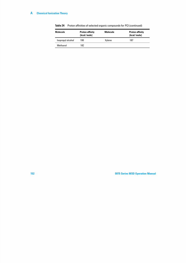
7/14/2019 Agilent 5973 MS User Manual
http://slidepdf.com/reader/full/agilent-5973-ms-user-manual 152/162
152 5975 Series MSD Operation Manual
Chemical Ionization Theory A
Hydride abstraction
In the formation of reagent ions, various reactant ions can be formed that have
high hydride-ion (H–) affinities. If the hydride-ion affinity of a reactant ion is
higher than the hydride-ion affinity of the ion formed by the analyte's loss of
H–, then the thermodynamics are favorable for this chemical ionization
process. Examples include the hydride abstraction of alkanes in methane
chemical ionization. In methane CI, both CH5+ and C2H5
+ are capable of
hydride abstraction. These species have large hydride-ion affinities, which
results in the loss of H– for long-chain alkanes, according to the general
reaction
R+ + M [M–H]+ + RH
For methane R+ is CH5+ and C2H5
+ and M is a long-chain alkane In the case
7/14/2019 Agilent 5973 MS User Manual
http://slidepdf.com/reader/full/agilent-5973-ms-user-manual 153/162
5975 Series MSD Operation Manual 153
For methane, R is CH5 and C2H5 , and M is a long chain alkane. In the case
of CH5+, the reaction proceeds to form [M–H]+ + CH 4+ H2. The spectra
resulting from hydride abstraction will show an M–1 m/z peak resulting from
the loss of H–. This reaction is exothermic so fragmentation of the [M–H]+ ion
is often observed.
Often, both hydride-abstraction and proton-transfer ionization can be evident
in the sample spectrum. One example is the methane CI spectrum of
long-chain methyl esters, where both hydride abstraction from the
hydrocarbon chain and proton transfer to the ester function occur. In the
methane PCI spectrum of methyl stearate, for example, the MH+ peak at
m/z 299 is created by proton transfer and the [M–1]+ peak at m/z 297 is
created by hydride abstraction.
AdditionFor many analytes, proton-transfer and hydride-abstraction chemical
ionization reactions are not thermodynamically favorable. In these cases,
reagent gas ions are often reactive enough to combine with the analyte
molecules by condensation or association (addition reactions). The resulting
ions are called adduct ions. Adduct ions are observed in methane chemical
ionization by the presence of [M+C2H5]+ and [M+C3H5]+ ions, which result in
M+29 and M+41 m/z mass peaks. Addition reactions are particularly important in ammonia CI. Because the
NH3 has a high proton affinity, few organic compounds will undergo proton
transfer with ammonia reagent gas. In ammonia CI, a series of ion-molecule
reactions takes place, resulting in the formation of NH4+, [NH4NH3]+, and
[NH4(NH3)2]+. In particular, the ammonium ion, NH4+, will give rise to an
A Chemical Ionization Theory
intense [M+NH4]+ ion observed at M+18 m/z , either through condensation or
association. If this resulting ion is unstable, subsequent fragmentation may be
observed. The neutral loss of H2O or NH3, observed as a subsequent loss of 18
or 17 m/z , respectively, is also common.
Charge exchange
Charge-exchange ionization can be described by the reaction:
X+· + M M+· + X
where X+ is the ionized reagent gas and M is the analyte of interest. Examples
of reagent gases used for charge exchange ionization include the noble gases(helium, neon, argon, krypton, xenon, and radon), nitrogen, carbon dioxide,
carbon monoxide hydrogen and other gases that do not react “chemically”
7/14/2019 Agilent 5973 MS User Manual
http://slidepdf.com/reader/full/agilent-5973-ms-user-manual 154/162
154 5975 Series MSD Operation Manual
carbon monoxide, hydrogen, and other gases that do not react chemically
with the analyte. Each of these reagent gases, once ionized, has a
recombination energy expressed as:
X+· + e– X
or simply the recombination of the ionized reagent with an electron to form a
neutral species. If this energy is greater than the energy required to remove anelectron from the analyte, then the first reaction above is exothermic and
thermodynamically allowed.
Charge-exchange chemical ionization is not widely used for general analytical
applications. It can, however, be used in some cases when other chemical
ionization processes are not thermodynamically favored.
Chemical Ionization Theory A
Negative CI Theory
Negative chemical ionization (NCI) is performed with analyzer voltage
polarities reversed to select negative ions. There are several chemicalmechanisms for NCI. Not all mechanisms provide the dramatic increases in
sensitivity often associated with NCI. The four most common mechanisms
(reactions) are:
• Electron capture
• Dissociative electron capture
• Ion pair formation
• Ion-molecule reactions
I ll f th t th i l l ti th t
7/14/2019 Agilent 5973 MS User Manual
http://slidepdf.com/reader/full/agilent-5973-ms-user-manual 155/162
5975 Series MSD Operation Manual 155
In all of the cases except the ion-molecule reactions, the reagent gas serves a
function different from the function it serves in PCI. In NCI, the reagent gas is
often referred to as the buffer gas. When the reagent gas is bombarded with
high energy electrons from the filament, the following reaction occurs:
Reagent gas + e– (230eV) Reagent ions + e– (thermal)
If the reagent gas is methane (Figure 36), the reaction is:
CH4 + e– (230eV) CH4+ + 2e–
(thermal)
The thermal electrons have lower energy levels than the electrons from the
filament. It is these thermal electrons that react with the sample molecules.
There are no negative reagent gas ions formed. This prevents the kind of
background that is seen in PCI mode and is the reason for the much lower
detection limits of NCI. The products of NCI can only be detected when the
MSD is operating in negative ion mode. This operating mode reverses the
polarity of all the analyzer voltages.
Carbon dioxide is often used as a buffer gas in NCI. It has obvious cost,
availability, and safety advantages over other gases.
A Chemical Ionization Theory
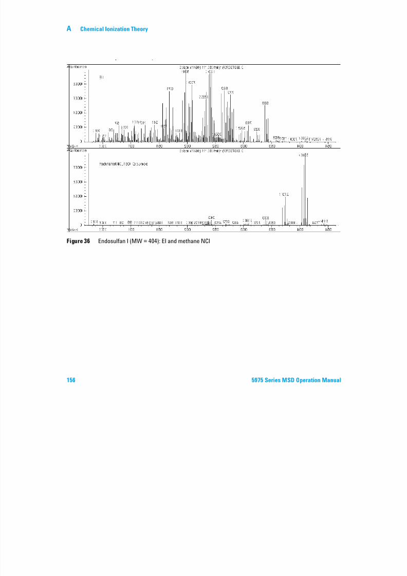
7/14/2019 Agilent 5973 MS User Manual
http://slidepdf.com/reader/full/agilent-5973-ms-user-manual 156/162
156 5975 Series MSD Operation Manual
Figure 36 Endosulfan I (MW = 404): EI and methane NCI
Chemical Ionization Theory A
Electron capture
Electron capture is the primary mechanism of interest in NCI. Electron
capture (often referred to as high-pressure electron capture mass
spectrometry or HPECMS) provides the high sensitivity for which NCI isknown. For some samples under ideal conditions, electron capture can provide
sensitivity as much as 10 to 1000 times higher than positive ionization.
Note that all the reactions associated with positive CI will also occur in NCI
mode, usually with contaminants. The positive ions formed do not leave the
ion source because of the reversed lens voltages, and their presence can
quench the electron capture reaction.
The electron capture reaction is described by:
MX + e–(th l) MX–·
7/14/2019 Agilent 5973 MS User Manual
http://slidepdf.com/reader/full/agilent-5973-ms-user-manual 157/162
5975 Series MSD Operation Manual 157
MX + e (thermal) MX
where MX is the sample molecule and the electron is a thermal (slow) electron
generated by the interaction between high energy electrons and the reagent
gas.
In some cases, the MX–
·radical anion is not stable. In those cases the reverse
reaction can occur:
MX–· MX + e–
The reverse reaction is sometimes called autodetachment. This reverse
reaction generally occurs very quickly. Thus, there is little time for the
unstable anion to be stabilized through collisions or other reactions.
Electron capture is most favorable for molecules that have hetero-atoms. For
example: nitrogen, oxygen, phosphorus, sulfur, silicon, and especially thehalogens: fluorine, chlorine, bromine, and iodine.
The presence of oxygen, water, or almost any other contaminant interferes
with the electron-attachment reaction. Contaminants cause the negative ion to
be formed by the slower ion-molecule reaction. This generally results in less
sensitivity. All potential contamination sources, especially oxygen (air) and
water sources, must be minimized.
A Chemical Ionization Theory
Dissociative electron capture
Dissociative electron capture is also known as dissociative resonance capture.
It is a process similar to electron capture. The difference is that during the
reaction, the sample molecule fragments or dissociates. The result is typically an anion and a neutral radical. Dissociative electron capture is illustrated by
the reaction equation:
MX + e–(thermal) M· + X–
This reaction does not yield the same sensitivity as electron capture, and the
mass spectra generated typically have lower abundance of the molecular ion.
As with electron capture, the products of dissociative electron capture are not always stable. The reverse reaction sometimes occurs. This reverse reaction is
sometimes called an associative detachment reaction. The equation for the
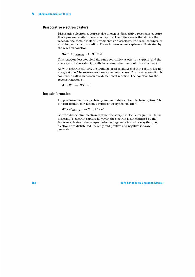
7/14/2019 Agilent 5973 MS User Manual
http://slidepdf.com/reader/full/agilent-5973-ms-user-manual 158/162
158 5975 Series MSD Operation Manual
sometimes called an associative detachment reaction. The equation for the
reverse reaction is:
M· + X– MX + e–
Ion pair formation
Ion pair formation is superficially similar to dissociative electron capture. The
ion pair formation reaction is represented by the equation:
MX + e–(thermal) M+ + X¯ + e–
As with dissociative electron capture, the sample molecule fragments. Unlike
dissociative electron capture however, the electron is not captured by the
fragments. Instead, the sample molecule fragments in such a way that the
electrons are distributed unevenly and positive and negative ions aregenerated.
Chemical Ionization Theory A
Ion-molecule reactions
Ion-molecule reactions occur when oxygen, water, and other contaminants are
present in the CI ion source. Ion-molecule reactions are two to four times
slower than electron-attachment reactions and do not provide the highsensitivity associated with electron capture reactions. Ion-molecule reactions
can be described by the general equation:
M + X– MX–
where X– is most often a halogen or hydroxyl group that was created by
ionization of contaminants by electrons from the filament. Ion-molecule
reactions compete with electron capture reactions. The more ion-molecule
reactions that occur, the fewer electron capture reactions occur.
7/14/2019 Agilent 5973 MS User Manual
http://slidepdf.com/reader/full/agilent-5973-ms-user-manual 159/162
5975 Series MSD Operation Manual 159
A Chemical Ionization Theory

7/14/2019 Agilent 5973 MS User Manual
http://slidepdf.com/reader/full/agilent-5973-ms-user-manual 160/162
160 5975 Series MSD Operation Manual

7/14/2019 Agilent 5973 MS User Manual
http://slidepdf.com/reader/full/agilent-5973-ms-user-manual 161/162
Agilent Technologies

7/14/2019 Agilent 5973 MS User Manual
http://slidepdf.com/reader/full/agilent-5973-ms-user-manual 162/162
© Agilent Technologies, Inc.
Printed in USA, June 2012