
Agilent 1290 Infinity II Ultra Low Dispersion Kit ... · The 1290 Infinity II Ultra-Low Dispersion...
8
Agilent Technologies Agilent 1290 Infinity II Ultra Low Dispersion Kit Technical Note 1290 Infinity II Ultra Low Dispersion Kit - Technical Note In this note we describe how to install the Agilent 1290 Infinity II Ultra Low Dispersion Kit (5067-5963). Contents Introduction 2 Kit Contents 3 Installation 4 Install the High Pressure Needle Seat Assembly 4 Install the Heat Exchanger Assembly 6 Connect the Column 8
Transcript of Agilent 1290 Infinity II Ultra Low Dispersion Kit ... · The 1290 Infinity II Ultra-Low Dispersion...

Agilent 1290 Infinity II Ultra Low Dispersion Kit
Technical Note
1290 Infinity II Ultra Low Dispersion Kit - Technical NoteIn this note we describe how to install the Agilent 1290 Infinity II Ultra Low Dispersion Kit (5067-5963).
Contents
Introduction 2
Kit Contents 3
Installation 4
Install the High Pressure Needle Seat Assembly 4Install the Heat Exchanger Assembly 6Connect the Column 8
Agilent Technologies

Introduction
Introduction
2
The 1290 Infinity II LC has a large power range (2 mL/min at 1300 bar and 5 mL/min at 800 bar) and low system dispersion and is therefore designed for a broad application range with 2.1 mm to 4.6 mm inner diameter columns. The 1290 Infinity II Ultra-Low Dispersion Kit (5067-5963) allows a further reduction of the extra column
volume* of the 1290 Infinity II LC by using capillaries with a low internal diameter of 0.075 mm, which are marked by black sleeves.
This kit is recommended for following applications:
• isocratic separations on 2.1 mm inner diameter, especially with early eluting peaks
• gradient separations on 2.1 mm, especially if the peaks of interest are eluting very early in the isocratic part of the gradient Applications on 1 mm inner diameter columns will also benefit from the lower extra column volume.
Since small diameter capillaries in this kit will significantly increase the
backpressure† of the system at high flow rates, it is recommended to use the kit only for the applications mentioned above.
The 1290 Infinity II Ultra-Low Dispersion Kit (5067-5963) is designed for the use with an Agilent 1290 Infinity II System.
* The volume between the effective injection point and the effective detection point, excluding the part of the
column containing the stationary phase is called extra column volume. This volume contributes to the band broadening and should be significantly smaller than the volume of the eluted peak. The use of smaller columns (short length, narrow diameter and smaller/more efficient particles) results in smaller peak volumes, which then also require a smaller extra column volume in order to avoid a loss of efficiency.† for example +165 bar with water at 1 mL/min flow rate

Kit Contents
Kit Contents
p/n Description
5500-1208 Capillary ST 0.075 mm x 250 mm ULD-Kit Inf-IIColumn outlet to Flow Cell (use A-Line Quick Turn Fitting for column connection)
5500-1207 Capillary ST 0.075 mm x 500 mm ULD-Kit Inf-IIMultisampler to Heat exchanger
G4267-87020 High Pressure Seat Assembly 0.075 mm (PEEK)
G7116-60021 Quick Connect Heat exchanger Ultra Low Dispersion
5067-6602 A-Line QC/QT Assy ST 0.075 mm x 105 mmHeat exchanger to column
In case of a required replacement of one of the capillaries from this kit please use the following part numbers for re-order:
p/n Description
5067-5966 A-Line Quick Turn fitting
5500-1205 Capillary ST 0.075 mm x 500 mmCapillary for use with Quick Turn Fitting
5500-1206 Capillary ST 0.075 mm x 250 mmCapillary for use with Quick Turn Fitting
5067-5965 A-Line Quick Connect LC fittingQuick Connect Fitting without capillary
5500-1174 A-Line Capillary ST 0.075 mm x 105 mmCapillary for use with Quick Connect Fitting
5043-0924 Front FerruleReplacement Part for Quick Turn & Quick Connect Fitting
3
Installation Install the High Pressure Needle Seat Assembly
Installation
Install the High Pressure Needle Seat Assembly
4
Tools required p/n Description
8710-0510 Wrench open 1/4 — 5/16 inch
Flat head screwdriver
Parts required p/n Description
G4267-87020 High Pressure Seat Assembly 0.075 mm (PEEK)
Preparations In order to avoid leaks, stop the pump running and remove the tubings from the solvent bottles. If available close the shutoff valves.
Risk of injury by uncovered needle
An uncovered needle is a risk of harm to the operator.
➔ Do not open the safety lock of the needle assembly
➔ Be careful working at the z-robot.
➔ Wear safety goggles, when removing the needle assembly.
WARNING
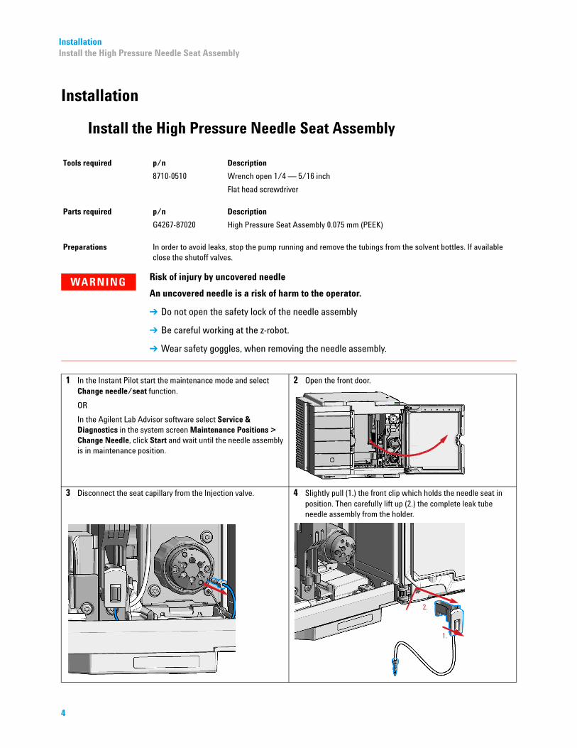
1 In the Instant Pilot start the maintenance mode and select Change needle/seat function.
OR
In the Agilent Lab Advisor software select Service & Diagnostics in the system screen Maintenance Positions > Change Needle, click Start and wait until the needle assembly is in maintenance position.
2 Open the front door.
3 Disconnect the seat capillary from the Injection valve.
4 Slightly pull (1.) the front clip which holds the needle seat in position. Then carefully lift up (2.) the complete leak tube needle assembly from the holder.

InstallationInstall the High Pressure Needle Seat Assembly
5 Insert the new Needle seat (1.). Press it firmly in position (2.).
NOTEVerify that the needle seat clip is locked in the needle park station.
6 Reconnect the seat capillary to the injection valve.
7 In the Instant Pilot close Change needle /seat.
OR
In the Agilent Lab Advisor software Change needle click End and wait until the needle assembly is in the needle park position.
8 Close the front door.
9 Perform a pressure test.
5

Installation Install the Heat Exchanger Assembly
Install the Heat Exchanger Assembly
6
Tools required p/n Description
5023-2502 Hex driver 1/4 inch, slitted
8710-0510 Wrench open 1/4 — 5/16 inch
Parts required p/n Description
G7116-60021 Quick Connect Heat exchanger Ultra Low Dispersion
5067-6602 A-Line QC/QT Assy ST 0.075 mm x 105 mm
5500-1207 Capillary ST 0.075 mm x 500 mm ULD-Kit Inf-II
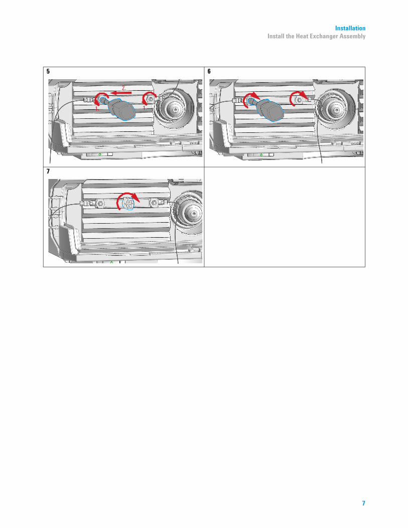
1 Choose one of the possible positions for placing the heat exchanger.
NOTEUse one of the four central positions if only one column is used.
NOTEFollow the special instructions provided for the A-Line Quick Connect and Quick Turn Fittings.
2 Connect the A-Line QC/QT Assy ST 0.075 mm x 105 mm (5067-6602) to the Quick-Connect Heat Exchanger ULD using the standard stainless steel fitting.
3 Position the Heat Exchanger as shown (1.). Fix it with a hex driver (2.).
4 Install Capillary ST 0.075 mm x 500 mm ULD-Kit Inf-II (5500-1207) between port 6 of the multisampler injection valve and the heat exchanger.
InstallationInstall the Heat Exchanger Assembly
5 6
7
7
Installation Connect the Column
Connect the Column
*01200-90*01200-9001200-90106
Tools required p/n Description
5023-0240 Hex driver, ¼", slitted
8710-0510 Wrench open 1/4 — 5/16 inch
Parts required p/n Description
5067-6602 A-Line QC/QT Assy ST 0.075 mm x 105 mm
5500-1208 Capillary ST 0.075 mm x 250 mm ULD-Kit Inf-II
Preparations A-Line QC/QT Assy ST 0.075 mm x 105 mm (5067-6602) connected to the heat exchanger, see “Install the Heat Exchanger Assembly” on page 6.
1 Connect the A-Line QC/QT Assy ST 0.075 mm x 105 mm (5067-6602) from the heat exchanger to the column.
NOTE Turn the column on to the A-Line Quick Connect Fitting.
Use a wrench to counter the column while tightening the capillary fitting.
2 Install Capillary ST 0.075 mmx 250 mm ULD-Kit Inf-II (5500-1208) between the column and the detector flow cell (Quick Turn fitting to the column).
3 Position the column into the column holder clip.
106*106*
Part Number: 01200-90106
Edition: 06/2016Printed in Germany
© Agilent Technologies, Inc 2014-2015, 2016
Agilent Technologies, IncHewlett-Packard-Strasse 8
76337 WaldbronnGermany


![Agilent 1290 Infinity LC 월등히 강력해진 성능 · 1290 Infinity LC 액체 이송 시스템의 뛰어난 기능과 차세대 ... 510 505 &' O[ Ï] 495 8.5 9.0 ... • 램프](https://static.fdocuments.net/doc/165x107/5b8a66067f8b9aa81a8e79ff/agilent-1290-infinity-lc-1290-infinity-lc-.jpg)


