
Agard-Ag-183(Principles of Avionics Computer Systems)
193
. P201447 N«ii3 A AGARD-AG-183 oo • < 6 < * • < \ o < AGARDograph No. 183 o n Principles o f Avionics Computer Systems Edited b y J.N.Bloom NOR TH ATLANTIC TRE AT Y ORGANIZATION - DISTRIBUTION A ND AVAILABILITY ON BACK COVER
Transcript of Agard-Ag-183(Principles of Avionics Computer Systems)

7/29/2019 Agard-Ag-183(Principles of Avionics Computer Systems)
http://slidepdf.com/reader/full/agard-ag-183principles-of-avionics-computer-systems 1/192
.
P 2 0 1 4 4 7 N « i i 3A
A G A R D - A G - 1 8 3
o o•
<
6< * •
< \o<
A G A R D o g r a p h No. 183
o n
Principles of AvionicsComputer Systems
Edited by
J.N.Bloom
NORTH ATLANTIC TREATY ORGANIZATION -
D I S T R I B U T I O N AND A V A I L A B I L I T YO N B A C K C O V E R

7/29/2019 Agard-Ag-183(Principles of Avionics Computer Systems)
http://slidepdf.com/reader/full/agard-ag-183principles-of-avionics-computer-systems 2/192

7/29/2019 Agard-Ag-183(Principles of Avionics Computer Systems)
http://slidepdf.com/reader/full/agard-ag-183principles-of-avionics-computer-systems 3/192
AGARD-AG-183
NORTH ATLANTIC TREATY ORGANIZATION
ADVISORY GROUP FOR AEROSPACE RESEARCH AND DEVELOPMENT
(ORGANISATION DU TRAITE DE L'ATLANTIQUE NORD)
AGAR Dograph No. 183
PRINCIPLES OF AVIONICS COMPUTER SYSTEMS
Edited by
J.N.Bloom
Communications Research CentreCommunicat ions Canada
This AGARDograph has been prepared at the request of the Avionics Panel of AGARD.
7/29/2019 Agard-Ag-183(Principles of Avionics Computer Systems)
http://slidepdf.com/reader/full/agard-ag-183principles-of-avionics-computer-systems 4/192
THE MISSION OF AGARD
The mission of AGARD is to bring together the leading personali t ies of the NATO nations in the fields of
science and technology relat ing to aerospace for the fo l lowing purposes:
Exchanging of scient i f ic and technical informat ion;
— Cont inuously s t imulat ing advances in the aerospace sciences relevant to s t rengthening the common defence
pos t u re ;
— Improving the co-operat ion among member nat ions in aerospace research and development ;
— Providing scientific and technical advice and assistance to the North Atlantic Mili tary Committee in the
f ield of aerospace research and development ;
— Render ing scient i f ic and technical assi s tance, as requested, to o ther NATO bodies and to member nat ions
in connect ion wi th research and development problems in the aerospace f ield ;
Providing assi s tance to member nat ions for the purpose of increasing thei r scient i f ic and technical potent ial ;
— Recommending effect ive ways for the member nat ions to use thei r research and development capabi l i t i es
fo r t he common benef i t o f t he NATO communi t y .
The highest autho r i ty w i th in AG ARD is the Nat ional D elegates Board consis ting of official ly appo inted senior
representat ives f rom each m emb er nat ion. The mission of AGA RD is carr ied out thro ugh the Panels which are
composed of exper t s appointed by the Nat ional Delegates , the Consul tant and Exchange Program and the Aerospace
Appl icat ions Studies Program. The resul t s of AG AR D work are repor te d to the mem ber nat ions and the NATO
Author i t ies through the AGARD ser ies of publ icat ions of which th is i s one.
Part ic ipation in AG AR D activit ies is by invitat ion on ly and is norm ally l imited to ci t izens of the NAT O na tions.
Publ i shed December 1974
Copyr i gh t © AGA RD 1974
6 8 1 . 3 2 : 6 2 9 . 7 3 . 0 5
*
Set and p r i n t ed by Techn i ca l Ed i t i ng and Reproduct i on Lt d
Har fo rd House , 7 - 9 Char l o t t e S t . London . WIP IHD

7/29/2019 Agard-Ag-183(Principles of Avionics Computer Systems)
http://slidepdf.com/reader/full/agard-ag-183principles-of-avionics-computer-systems 5/192
LIST OF CONTRIBUTORS
Chapter 1 INTRODUCTIONJ.N.BloomCommunications Research Centre
Comm unications Canada
Chapter 2 BASIC DIGITAL COMPUTER CONCEPTSProf. A.R.MeoInstituto di Elletrotecnica Generale,Politecnico di Torino, Italy
Chapter 3 DATA ACQUISITION AND COMMUNICATION FUNCTIONYngvar LundhNorwegian Defence Research Establishment
Chapter 4 OPTIMISATIONYngvar Lundh
Chapter 5 SYSTEMS AND SYSTEMS DESIGNDr C.S.E.PhillipsRoyal Radar Establishment, U.K.
Chapter 6 AVIONICS SYSTEM ARCHITEC TURER. E.WrightC.E. Digital Systems Development,Ferranti Ltd., Bracknell, U.K.
Chapter 7 DEFINING THE PROBLEM AND SPECIFYING THE REQUIREMENTSilvio Boesso and Rodolfo Gamberale,SELENIA, Industrie Elettroniche Associate SpA,Rome, Italy,
Chapter 8 MONITORING AND CONTROL OF AEROSPACE VEHICLE PROPULSIONE.S.EcclesSmiths Industries Ltd.,Aviation Division, U.K.
Chapter 9 MAN-MACHINE INTERFA CEDr E. KeonjianEngineering Consultant, U.S.A.
Chapter 10 NOVEL DEVICES AND TECHNIQUESDr E.Keonjian and Dr A.L.Freedman
Chapter 11 SPECIFYING THE REQUIREMENTSDr A.L.FreedmanThe Plessey Company Ltd., U.K.
Edited by J.N.Bloom
iii

7/29/2019 Agard-Ag-183(Principles of Avionics Computer Systems)
http://slidepdf.com/reader/full/agard-ag-183principles-of-avionics-computer-systems 6/192
C O N T E N T S
Page
1 . INTRODUCTION
1.1 Purpose of the boo k 1
1.2 Plan of the bo ok 1
2. BASIC DIGITAL COMPUTER CONCEPTS
2.1 The Fun ct ional Uni t s of a Com pute r 3
2.2 Flip-Flop s and Registers 4
2.3 Num eric Informa t ion coding in a Com puter S
2.4 Boolean Algebra 10
2.5 Building Blocks 14
2.6 The Ari thm et ic Uni t 20
2.7 The Mem ory 21
2.8 The Con t rol Uni t 23
2.9 Inpu t -Ou tput Devices 26
2.10 Sof tware 27
3. DATA ACQUISITION AND COMM UNICATION FU NCTION
3.1 Typical Devices to which an Avionics Com pute r is Conn ected 30
3 .2 Dat a Types , Fo rms and Form at s 30
3.3 Cha racteris t ics of Data 31
3.4 A/D and D/A conversion 32
3.5 Com puter In terfacing 36
3.6 Data Transmission 38
3.7 The Program mer ' s View 41
4 . OPTIMISATION
4.1 The Op t i mi sa t i on Prob l em 42
4 .2 Impor t an t Paramet er s 43
4.3 Typical Trade-Off Si tuat ions 44
4.4 Method s of Determ ining Adequ acy 46
5 . SYSTEMS AND SYSTEMS DESIGN
5.1 Int rod uct io n 47
5.2 System s 47
5.3 System Design Method ology 48
5.4 Programs as System s 49
5.5 Fun ct iona l System Approa ch 51
5.6 Purpose of Programm ing Netw ork Diagrams 52
5.7 Data Recta ngles 52
5.8 Process Circles 55
5.9 Exam ple of a Simple Hierarchic Program Netw ork 56
5.10 Hierarchy of Diagrams 56
5.11 Simulat ion and Test ing 61
5.12 Real Tim e Co mp uter Systems 61
5.13 Hierarchical View point 62
6 . AVIONICS SYSTEM ARCH ITECT URE
6.1 Int rod uct io n 64
6.2 The Pract ical App roach 66
6.3 Me thods of Assessment of Com put ing Power and Inform at ion Rates 71
6.4 General Phi losophies and Trade-Offs 73
6.5 Rel iabi li ty Conside rat ions 78
6.6 Exam ples of Avionic System Arch i tecture 82
7 . D E F I N I N G T H E P R O B LE M A N D S P E C I F Y I N G T H E R E Q U I R E M E N T
7.1 Int ro duc t ion 88
7.2 Survey of Typ ical Task s of an Avionic Syste m 88
7 .3 From Opera t i ona l Requ i r emen t s t o Sys t em Func t i ons 89
7 .4 From Sys t em Funct i on t o Com put er Requ i r em en t s 92
7.4 .1 Presen tat ion of the Req ui rem ents 92
7.4 .2 An Exam ple Set of Elem entary Opera t ions 93
7.4 .3 Fun ct ion al Analysis 99
IV

7/29/2019 Agard-Ag-183(Principles of Avionics Computer Systems)
http://slidepdf.com/reader/full/agard-ag-183principles-of-avionics-computer-systems 7/192
Page
7.4.4 Translation of the Mo del
7.4.5 Mission Statistics
7.4.6 Mem ory for Data
7 .4 .7 Input -Output
7.4.8 Exec ut ion Times and Ins t ruct ion Set
7.4.9 Ins t ruct io n Word-Length and For ma t7.4.10 Memory for Program
7.4.11 Total Mem ory Requ iremen ts
103
105108
110
111
114117
117
8. MONITORING AND CON TROL OF AEROSPACE VEHICLE PROPULSION
8.1 Int roduct ion
8.2 Sta teme nt of the Problem
8.3 The Requirem ents of Propuls ion Con trol and Moni toring
8.4 Definition of Design Failure Characte ristics
8.5 Sys tem Select ion and Archi tectu re
8.6 Sys tem Archi tectu re
8.7 Moni toring in Digita l Com puter Sys tems
8.8 Date Acquis i t ion, Com mun icat ion and Process ing
8.9 Man-Machine Interface8.10 Practical Realization
8.11 Conclus ion
119119
121
125
126
132
135
136
138139
142
9. MAN-MACHINE INTER FAC E
9.1 Int roduct ion
9.2 Human Capabi l i ties and Limita t ioas of the Crew
9.3 Al locat ion of Fun ct ions to Man and Machine
9.4 Es tablishing Requirem ents for Informat ion Display and Manual and Auto mat ic Con trols
9.5 Design of the Man-M achine Interface
9.6 Equipm ent for Man-Machine Interface
143
143
143
144
144145
10 . NOVEL DEVICES AND TECHNIQUES
10.1 In t roduc t ion10.2 Large Scale Integration (LSI) Technology
10.3 Sem icondu ctor and Other Typ es of Mem ories
10.4 Large Scale Integration (LSI) Testing
10.5 Funct ional Tes t ing
10.6 Parametric Testing, D.C. and A.C.
10.7 Opto-Elect ron ic Devices
11 . SPECIFYING THE REQUREMENTS
11.1 Practical Definition of a System
11.2 Deriving the Specification of the System as a Whole
11.3 System Design
11.4 Devices and Techniques, An Overview
150150154
158
158
160
160
163
163
168177

7/29/2019 Agard-Ag-183(Principles of Avionics Computer Systems)
http://slidepdf.com/reader/full/agard-ag-183principles-of-avionics-computer-systems 8/192

7/29/2019 Agard-Ag-183(Principles of Avionics Computer Systems)
http://slidepdf.com/reader/full/agard-ag-183principles-of-avionics-computer-systems 9/192
CHAPTER 1
INTRODUCTION
J.N.Bloom
1.1 PURPOSE OF THE BOOK
Modern computer systems comprise a set of structures that continue to grow in complexity, size and diversity.To the uninitiated, the amount of information available that describes these structures appears overwhelming.
Often, career officers or civilian administrators with little or no computer systems background or experience
find themselves in a position where they are charged with a sole or joint responsibility for the acquisition of acom puter system. The purpose of this book is to provide these officers and ad ministrators of the NATO cou ntrieswith a package of information that will give them an understanding of the procedures involved in defining arequirement, specifying that requirement and, hopefully, of the convergent process that results in the satisfying ofthat requirement for a computer based system.
This book presents to officials of the NATO countries an introductory treatment of the principles underlyingthe computer systems encountered in avionics, and provides an insight into the structural organization of thosesystems. The book explains the methodology b ehind the specification, analysis, design and implem entation ofcom puter based systems. The tre atme nt of the m aterial emphasizes avionic systems, but the principles are relevantand applicable to all computer systems.
A systematic treatment in depth of all levels of computer organization is not possible in a book such as this.
While sufficient material has been included in the tex t to achieve the principal goal of the bo ok, th at it beeducational, extensive references will enable the interested reader to pursue certain topics of his or her specialinterest.
1.2 PLAN OF THE BOOK
The organization of the material in the book is such that the fundamentals of computers and basic conceptsare introduced in the early chapters . Gradually, the reader is introduced to the language of compu ter technologyand the vocabulary of systems terminology. The basic chapter of this book is Chap ter 2. The chapter serves as anintroduction to the subject for those readers coming to it for the first time, as well as a useful review for thosewho have been exposed to it in the past.
The next chapter, Chapter 3, introduces the reader to the problems of communicating with a machine, withthe preparation and form atting of input da ta. The task faced by the programm er in assembling a list of instructionsthat will cause the computer to carry out a desired function is carefully described.
Chapter 4, on optimization, discusses the important topic of definition of the problem for which solution thesystem is being assembled or acq uired. The reader is shown th at reality dic tates a set of choices amongstalternatives; there are no ideal optimal solutions .
The very complex subject of systems and system design is treated in Chap ter 5. Fund amen tal ideas areintroduced and used to develop a basis for the next level of co ncepts. The goal is to give the reader an insight intocurrent concepts in design philosophy and methodology in systems.
Chapter 6 on Avionics System Architecture provides the reader with a logical approach to the problem of
determining the size of system required. The trade-offs and comprom ises that mu st be considered in arriving at asuitable system configuration are presented so that the reader can appreciate the problems posed by choosing fromsets of alternatives. Some examples of typical systems are given to illustrate the ideas embodied in the tex t.
Chap ter 7 is a comprehensive chapter on a higher level than th e preceding material. The fundam ental ideasare introduced anew here, and brought to the point where the analysis of a typical, complex problem is undertaken.

7/29/2019 Agard-Ag-183(Principles of Avionics Computer Systems)
http://slidepdf.com/reader/full/agard-ag-183principles-of-avionics-computer-systems 10/192
The chapter develops more rapidly than the preceding ones, and is recommended for those readers with somebackground in computing machines.
Chap ter 8 illustrates how the material of the preceding chapters may be used. The chapter analyzes theproblem of the mo nitoring and co ntrol of aerospace vehicle prop ulsion. The reader can trace the application ofthe principles introduced and discussed in the earlier chapters.
A problem area introdu ced in preceding chapters is enlarged on in Chap ter 9. The problem of the man-machine
interface is of param oun t im portanc e and receiving a lot of atten tion from workers all over the world: bu t anexhaustive treatm ent of the man-m achine interface is not possible in a book of this kind. Rath er, some basicnotions are introduced and the reader is left to follow up his interest by further reading.
Cha pter 10, too , is only of an introd ucto ry n ature . Sufficient inform ation is given to show the many aspectsof semi-conductor technology today, and to indicate the variety of devices that contend for the designers attentionwhen implementing a system.
Chapter 11 is synoptic in nature, giving an overview of the book with some insight into the relationship of theparts. The great experience and insight that the author has into the problems of specifying computer systemsrequirem ents is eviden t; the reader will at once becom e familiar with some of the do 's and don 'ts of systemacquisition.

7/29/2019 Agard-Ag-183(Principles of Avionics Computer Systems)
http://slidepdf.com/reader/full/agard-ag-183principles-of-avionics-computer-systems 11/192
CHAPTER 2
BASIC DIGITAL COMPUTER CONCEPTS
A.R.Mao
2.1 THE FUNCTIONAL UNITS OF A COMPUTER
A digital computer is usually viewed as consisting of five functional units : arithme tic unit, me mory, c ontrolunit, input devices and ou tpu t devices. The block diagram of such an organization is shown in Figure 2. 1.
I
INPUT
DEVICES
A1l
1
1
w
*
ARITHMETIC
UNIT
^
i 1
MEMORY
_3
i
r
i
CONTROL
UNIT
OUTPUT
DEVICES
4i11
__
__.
-• TRUE INFORMATION
•• COMMAND SIGNAL
Fig.2.1 The functional units of a com pute r
The arithmetic unit is the device where information is processed, that is, the arithmetical and logical operationsinvolved in a given program are performed.
The memory is the set of devices where is stored information currently no t in use. Stored informationincludes: the numerical data to be processed; the sequence of the operation s to be performed o n the numerical dataor program ; the intermed iate results; the final results to be delivered to the outp ut. What is essential for aninformation processing system to be considered a computer, or, more accurately, a stored-program computer, is
that mem ory should contain not only the problem data but also the program. Thu s, for example, a desk calculator,which is functionally equivalent to the arithmetic unit a lone, is not considered a compu ter. If the numerical dataand the program can be as easily changed in the mem ory, the system is called a general-purpose com puter, sinceit is hardly limited in the num ber of applications of any given type for which it can be used. In many airbornecomputers changing the content of the program memory implies a "rewiring of the machine", which is a relatively

7/29/2019 Agard-Ag-183(Principles of Avionics Computer Systems)
http://slidepdf.com/reader/full/agard-ag-183principles-of-avionics-computer-systems 12/192
complex op eratio n. This drawback can be accepted when th e system is designed for solving a specific class ofproblems, and in this case the system is referred to as a special-purpose computer.
The input and output devices perform the functions of receiving and delivering the incoming and outgoinginformation, respectively.
The contro l unit issues comm and and co ntrol signals to the remaining functional u nits of the system. Itreceives information pertaining to the program from the memory and assigns tasks, one at a time, to the other
units.
2.2 FLIP-FLOPS AND REGISTERS
Flip-flops
Engineering considerations based on the analysis of cost, reliability and dimension have led to the conclusionthat the best hardware atom is the bistable device, or flip-flop. The symb ol for the flip-flop is shown inFigure 2.2.
1 OUTPUT 0 OUTPUTik . i l
Fig.2.2 The flip-flop
At pres ent, a flip-flop consists of a pair of active elements (e.g., transistors) w orking reciprocally. When oneof them passes current, th e othe r is op en; and vice versa. This implies that a flip-flop has states, arbitrarilylabelled 0 and 1. The inform ation pertaining to the state of the flip-flop is delivered to the ou tpu t by means ofthe lines 0 outp ut and 1 ou tpu t. When the system is in the 0 state, the 0 output line is excited and the 1 outp ut
line is not exc ited. The con trary o ccurs when the system is in the 1 state.
Three lines ente r the block of Figure 2.2 one of the m being often missing. A signal on the line labelled R(reset) sets the device to its 0 state, regardless of its present state . A signal on the line labelled S (set) sets thesystem to its 1 state , regardless of its present state. A signal on the line labelled C (comp leme ntation ) changes thestate of the system.
A flip-flop can be set or reset in a few nano seconds or tens depend ing on the type of logic used. Itscon tent can be read as fast as a signal can scan the ou tpu t. In principal, a flip-flop is a mem ory elem ent; indeed,it is the smallest mem ory elem ent, since it holds the inform ation expressed by one binary digit, or bit. However,since its cost is relatively high, it is seldom used as an elementary unit of the true memo ry of a comp uter. Usually,flip-flops are introduced into all the functional units of a computer, especially the authmetic unit, as temporary,fast-access storage devices.
Registers
A register is an ordered set of flip-flops (or any oth er one-bit storage devices). Ther efore, th e conte nt of aregister is an ordered set of binary d igits, or bits, which can be interpreted as a binary num ber. This ordered setof bits is often called a "word".

7/29/2019 Agard-Ag-183(Principles of Avionics Computer Systems)
http://slidepdf.com/reader/full/agard-ag-183principles-of-avionics-computer-systems 13/192
Figure 2.3 shows the symbol for the parallel register, namely, the one in which all the bits are set inparallel. Notice the doub le lines indicating the several signal lines transmit inform ation into , or out of, th e register,and the single line indicating the command signal on receipt of which the new word is introduced into the register.
INPUT
INFORMATION
VL
COMMAND
VOUTPUT
INFORMATION
Fig.2.3 The symbol for the parallel register
The serial register is a register, that can receive and transmit only a single bit of information at a time. For
exam ple, the new bit is received at the left end and th e out put bit is delivered at the right end. The symbol forthe serial register is shown in Figure 2.4 w here th e single line labelled "sh ift" indicates the command signal onreceipt of which a new bit is received (and a new bit is delivered at the output).
OUTPUT H
INFORMATION
. INPUTINFORMATION
Fig.2.4 The symbol for the serial register
A particular type of serial register is the shift-register. On receipt of a command signal, a new bit is received a tone end and the information content of any component flip-flop is transmitted one step toward the other end.However, the information content of the whole register can be read in parallel.
2.3 NUMERIC INFORMATION CODING IN A COMPUTER
Because of the binary nature of the registers and the other building blocks, a computer is commonly built tohandle ordered sets of binary digits. Such ordered sets can represent numb ers or, more in general, combined alphabetic and numeric informa tion, according to certain assumed codes. In this section, we shall briefly p resent awidespread way of representing binary numbers and performing arithmetical operations.
Binary Numbers
A common way of representing a number as a sequence of binary digits consists in viewing the number as anordered set of decimal digits and representing each decimal digit with a combination of four bits according to a

7/29/2019 Agard-Ag-183(Principles of Avionics Computer Systems)
http://slidepdf.com/reader/full/agard-ag-183principles-of-avionics-computer-systems 14/192
specified code . A possible code for represen ting a decimal digit in binary form could be the one reported inTable 2.1. Thus, the number 378 would be represented as
0011 00111 1000
This coding way, commonly referred to as "binary coded decimal" (BCD) has a heavy drawback. Since thenumber of the combinations of four bits is 16 and there are only ten decimal digits, six combinations are assigned.Thus, for example, the sequence 1010 1111 is not used for representing any numb er. Therefo re, the average
number of binary digits used in this representation technique is larger than the strictly necessary one, and thisresults in a loss of efficiency.
TABLE 2.1
Representation of a Decimal Digit in Binary Code
DIGIT
01
2
3
4
5
6
7
8
9
C O D E
00000001
0010
0011
0100
0101
0110
0111
1000
100110101
1011
1100
1101
1110llllj
• not allowed
This drawback is overcome by continuing the representation law indicated in Table 2.1 as shown in Table 2.2.
This code is called "pu re binary c od e" , and is specified by th e following r elation. A sequence of binary digits
an an_i ... a, ao . a_, a_2 ...
describes the number
N = an 2 n + an_, 2"- 1 + ... + a t 2 + a0 1 + a_, 2 ' 1 + a_2 2 " 2 + ...
TABLE 2.2
Representation in Pure Binary Code
DIGIT
•
10
11
12
1314
15
16
17••
•
C O D E
1010
1011
1100
1101
1110
m i10000
10001••
•

7/29/2019 Agard-Ag-183(Principles of Avionics Computer Systems)
http://slidepdf.com/reader/full/agard-ag-183principles-of-avionics-computer-systems 15/192
Single-bit Arithmetic
Binary arithmetic is based on single-bit arithme tic. The add ition of tw o single bits, an augend bit and an addendbit, gives a sum bit and a carry bit according to the following rules:
AUGEND ADDEND CARRY SUM
BIT BIT BIT BIT
0 + 0 = 0 0
0 + 1 = 0 11 + 0 = 0 11 + 1 = 1 0
The multiplication of two single bits, a multiplicand bit and a multiplier one gives a single-bit product, accordingto the following rules:
MULTIPLICAND MULTIPLIER PRODUCT
BIT BIT BIT
0 x 0 = 00 x 1 = 01 x 0 = 01 x 1 = 1
These rules are the obvious applications of the well-known concepts of sum and multiplication to the binaryarithm etic. Similar rules can be introduced for defining binary subtra ction or division. The application of theserules to performing binary arithm etic is straightforward. For example, the sum of 101.01 and 100.11 can beperformed as follows:
1 1 1 1 c arry
1 0 1 . 0 1
1 0 0. 1 1
1 0 1 0. 0 0
Similary, the product of 110 by 101 is executed in the following way:
1 1 0
1 0 1
1 1 0
0 0 0
1 1 0
1 1 1 1 0
X
Two-complement
The two-complem ent of a given binary num ber N = a„ a,,., ... a! ao — a useful concep t for a widespreadway to represent negative numbers is defined as follows.
First the number
N * = 3n a n - i ••• * i *
is considered, which is obtained from N by comp lementing any bit. Then the num ber 00 ... 0 1, having onlyone bit equal to 1 in the least significant position of N*, is added to N*, thus obtaining a result R which is thetwo-complement of N.
For example, the two-complement of N = 0 1 0 1 1 0 0 is obtained as follows:
First step: N* = 1 0 1 0 0 1 1
1 1 carry
Second step: 1 0 1 0 0 1 1 +
1
R = 1 0 1 0 1 0 0

7/29/2019 Agard-Ag-183(Principles of Avionics Computer Systems)
http://slidepdf.com/reader/full/agard-ag-183principles-of-avionics-computer-systems 16/192
Representation of negative numbers
One of the most widespread techniques for representing the whole field of the relative numbers is the two-complement notation, which is defined as follows:
Positive numbers
A positive number is represented by a magnitude section containing the representation of the number in the
pure binary code, and a sign bit, which is a bit 0, to be imagined at the left of the most significant bit of themagnitude section. For ex ample, the number +3 is represented by
SIGN BIT MAGNITUDE SECTION
0 1 1
Negative numbers
A negative number is represented by the two-complement of the given number in the magnitude section andby 1 in the sign bit. For example, the number —1 is represented by
SIGN BIT MAGN ITUDE SECTION
1 1 1
Indeed, 11 is the two-complement of 1.
As a more complete example, Table 2.3 presents the list of the codes used for representing the field of theintegers from —4 to + 3 .
Notice that the representation sn of a number (where s denotes the sign bit and n the magnitude section) canbe interpreted to mean that the represented number is
sx(-4 ) + n .
The merits of this representation technique will be apparent after the properties of the two-complementarithmetic have been presented.
TABLE 2.3
Representation of the Integers from —4 to + 3 in Two-complement Notation
NUMBER
+3+2+ 1
0- 1- 2- 3
- 4
CODE
0 1 10 1 00 0 10 0 01 1 11 1 01 0 1
1 0 0
Addition in two-complement notation
The main advantage offered by two-complement notation is that the sum of two relative numbers can beperformed by using an adder for positive numb ers and interpre ting the sign bit as a magn itude bit. This is shownin the following examples.
Addition of a positive and negative number0 1 1
1 1 0
0 0 10 0 1
1 1 1
(+ 3)+
(- 2)
(+ 1)(+ 1)
+(" 1)
—1 0 0 0 (0 )
Notice that the left-most carry is to be discarded.

7/29/2019 Agard-Ag-183(Principles of Avionics Computer Systems)
http://slidepdf.com/reader/full/agard-ag-183principles-of-avionics-computer-systems 17/192
Addition of two positive numbers
0 1 0 ( + 2 )+
0 0 1 ( + 1 )
0 1 10 1 0
0 1 1
(+ 3)(+ 2)
+
(+ 3)1 0 1 overflow
Notice that in the second case the result is not correct, as is obvious, since the sum of +2 and +3 is outsidethe field of the represented n umbe rs. This overflow condition is shown by the fact th at the sign bit of the result isdifferent from the sign bits of the two addends.
Addition of two negative numbers
1 1 1 ( - 1 )
1 1 0 ( - 2 )
1 0 1
1 0 0
1 1 0
(
( -
(
3)
• 4)+
2)
1 0 1 0 overflow
In the second case the result is not correct, because the sum of —4 plus —2 is outside the field of the representednum bers. Also in this case the overflow condition is shown by the fact tha t the sign bit of the result is differentfrom the sign bits of the two addends.
Summing up, the addition of two relative numbers can be performed by using the sign bit as the mostsignificant of the magnitude bits, under the following two conditions:
(1) the left-most carry is to be neglected;
(2) the overflow co ndition may occur w hen the two adden ds have the same sign, and it is shown by thefact that the sign bit of the result is different from the sign bits of the two addend s.
Subtraction in two-complement notation
The simplest way to perform subtraction in two-complement notation is to add the two-complement of thesubtrahend to the minuend. On the other hand, the computation of the two-complement of a given number Ninvolves the complem entation of all the bits of N and the sum of the result and 1. It follows that b oth additionand subtraction require only an adder and a circuit for complemen ting the binary digits of a given number. Noticealso that m any registers have two compleme ntary o utp uts for any stored information bit; therefore , complem entinga bit corresponds merely to using the "complementary" output instead of the "true" output.
Other operations. Hardware and software implem entations
As in the usual decimal arithmetic, the product of two numbers is the sum of a certain set of rows, eachbeing obtained by multiplying the multiplicand by a digit of the multiplier and shifting the result a suitable numberof positions. In the binary case the m ultiplication of the m ultiplicand by a digit d is a very simple operation, sincethe result coincides with the given multiplicand if d is 1, and it is always 0 if d is 0.
Division and other arithmetical operations can be performed by using computation techniques which are thedirect application to the binary case of well-known algorithms.
All these operations can be implemented in "hard wa re" or in "softw are". We say that an operation isimplemented in "hardware" when a circuit is avilable in the computer, which can perform that operation directly.When a command, or a suitable set of commands, are given to that circuit, the content of one or more inputregisters are read, the given operation is performed and the result or the results are delivered to one or more output
registers. We say that an operation is implemented in "softw are", when the com puter circuits can only performelementary ope rations with respect to the given opera tions. This sequence constitue s a "sub-p rogram ", which iswritten in a memory device using a suitable code.
7/29/2019 Agard-Ag-183(Principles of Avionics Computer Systems)
http://slidepdf.com/reader/full/agard-ag-183principles-of-avionics-computer-systems 18/192
10
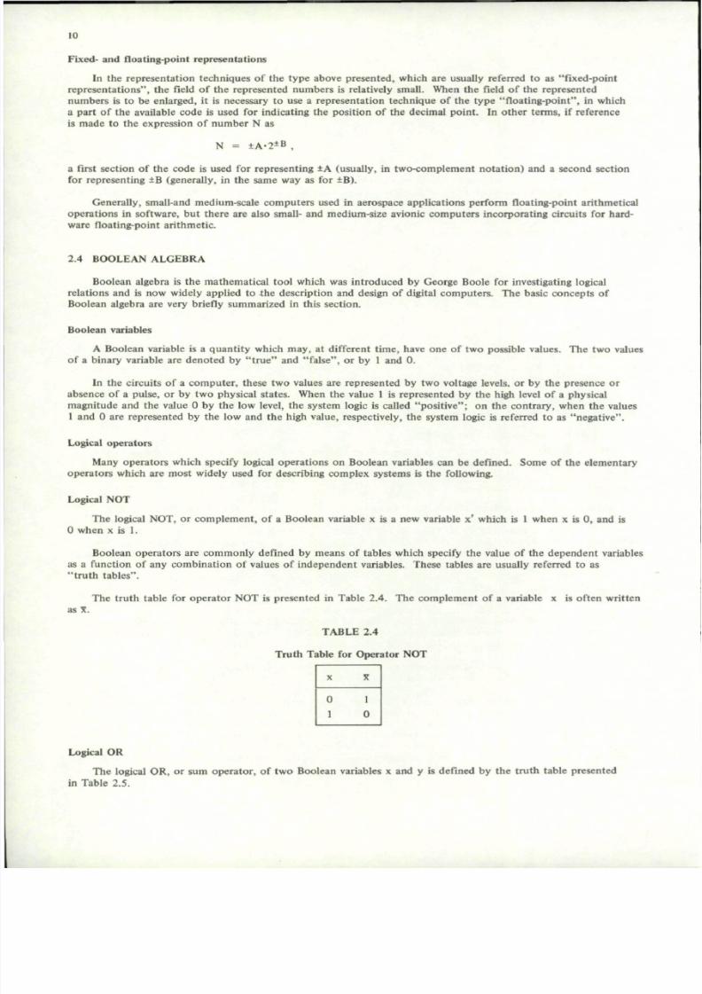
Fixed- and f loat ing-point repres entat ions
In the representat ion techniques of the type above presented, which are usual ly referred to as "f ixed-point
repre senta t ions" , the f ield of the represented num bers i s relatively smal l. When the f ield of the represe nted
numbers i s to be enlarged, i t i s necessary to use a representat ion technique of the type "f loat ing-point" , in which
a part of the available cod e is used for indicating the posit ion of the decimal poi nt . In oth er term s, if reference
is made to the expression of number N as
N = ± A - 2
± B
.
a f i rs t sect ion of the code i s used for represent ing ±A (usual ly , in two-co mp lem ent nota t ion) and a second sect ion
for representing ±B (generally, in the same way as for ±B).
Gene ral ly , smal l -and medium-scale com pute rs used in aerospace appl icat ion s perform f loating-point ar i thmet ical
operat ions in sof tware, but there are al so smal l - and medium-size avionic computers incorporat ing ci rcui t s for hard
ware f loat ing-point ar i thmet ic.
2 . 4 B O O L E A N A L G E B R A
Boolean algebra i s the mathemat ical tool which was in t roduced by George Boole for invest igat ing logical
relat ions and is now widely appl ied to the descr ip t ion and design of d igi tal com pute rs . The basic con cep ts of
Boolean algebra are very briefly summarized in this section.
Boolean var iables
A Boolean var iable i s a quant i t y w hich ma y, at d i fferent t im e, have one of two possible values. The two values
of a b inary var iable are den oted by "t ru e" and "f alse" , or by 1 and 0 .
In the ci rcui t s of a computer , these two values are represented by two vol tage levels , or by the presence or
abse nce of a pulse, or by tw o physical state s. When the value 1 is repr ese nted by the high level of a physic al
ma gni tude an d the value 0 by the low level , the system logic i s cal led "p osi t iv e"; on the con t rary , wh en the values
1 and 0 are represented by th e low and th e h igh value, respect ively , the system logic is referred to as "n ega t ive" .
Logica] operators
Many opera tors which speci fy logical oper at ions on Boolean var iables can be def ined. Some of the elem entary
ope rators w hich are most widely used for descr ib ing complex sy stems i s the fo l lowing.
Logical NOT
The logical NO T, or com ple m en t, of a Boolean variable x is a new variable x' which is 1 wh en x is 0, and is
0 when x is 1.
Boolean operators are commonly def ined by means of tables which speci fy the value of the dependent var iables
as a funct ion of any comb inat ion ot values of indepe nde nt var iables . These tables are usually referred to as
" t r u t h t a b l e s " .
The t ru th table for ope rator NOT is presen ted in Table 2 .4 . The com plem ent of a var iable x i s of ten w ri t ten
as X.
T A B L E 2 . 4
Tru t h Tab l e fo r Opera t o r NOT
Logical OR
The logical OR , or sum o pera tor , of two Boolean var iables x and y is def ined by the t ru th table presented
in Table 2 .5 .

7/29/2019 Agard-Ag-183(Principles of Avionics Computer Systems)
http://slidepdf.com/reader/full/agard-ag-183principles-of-avionics-computer-systems 19/192
II
TABLE 2.5
Truth Table for Operator OR
X
0
01
1
y
0
i0
1
x OR y
0
11
1
This definition can be generalized to the case of many indepen dent variables. The logical OR of n independent
variables x ,, x. xn is a new variable y which is 0 when all the independent variables are 0 and is 1 for anyothe r combination of values of independ ent variables. Variable y can also be written as y = x , + x2 + ... + x n .
Logical AND
The logical AND, or product operator, of two Boolean variables x and y is defined by the truth tablepresent in Table 2.6.
TABLE 2.6
Truth Table for Operator AND
x
0
0
1
1
y
0
1
0
1
x AND y
0
0
0
1
The definition can be generalized to the case of many ind epend ent variables. The logical AND of n indepen dent
variables x,, x. x n is a new variable y which is 1, when all the independent variables are 1, and it is 0 forany other comb ination of values of independent variables. Variable y can also be written as y = x , . x2 x n .
Logical coincidence
The logical "coincidence", or COIN operator, of two Boolean variables x and y is a variable z which is 1 whenx and y take the same logical value and is 0, otherwise. Therefo re, this ope rator is defined by the tru th table inTable 2.7.
TABLE 2.7
Truth Table for the Logical Coincidence
x
0
0
1
1
y
0
i
0
i
x COIN y
1
0
0
1
Logical EXOR
The logical EXOR, or exclusive-OR operator, of two variables x and y is defined by the truth table presented
in Table 2.8.

7/29/2019 Agard-Ag-183(Principles of Avionics Computer Systems)
http://slidepdf.com/reader/full/agard-ag-183principles-of-avionics-computer-systems 20/192
12
TABLE 2.8
Truth Table for Logical EXOR
x
0
0
1
1
y
0
i
0
1
x EXOR y
0
1
1
0
Notice that the truth table of logical EXOR differs from the one of logical OR only for the value associatedto the fourth row. This comparison explains why this operator is called "exclusive-OR", whereas the OR opera toris also referred to as "inclusive-O R". Notice also that the logical EXOR is the comp lemen t of the COIN o per ator
Operator NAND
The NAND operator is defined by the truth table presented in Table 2.9.
TABLE 2.9
Truth Table for NAND Operator
X
0
0
1
1
y
0
i
0
i
X N A N D y
1
1
1
0
Notice that this operator, as the name NAND (NOT-AND) suggests, is the complement of the AND operator.
The definition given in Table 9 can be generalized to the case of many independent variables.
Operator NOR
The NOR opera tor, as suggested by the nam e (NOT-OR), is the complement of the OR operator. Therefore,in the simple case of two independent variables, this operator is defined by the truth table present in Table 2.10.
TABLE 2.10
Truth Table for NOR Operator
X
00
1
1
y
0i
0
i
x NOR y
10
0
0
Implementation of a complex function by means of elementary operators
Any Boolean function, which has been described by means of a truth table, can be easily implemented in termsof OR, AND and N OT operators. By way of exam ple, let us consider the simple case of the Boolean functiondescribed by the tru th table presented in Table 1 1. It is easy to verify tha t the ou tpu t variable in the leastsignificant of the two digits generated by a circuit performing the binary addition of three binary digits (usually,the digits of a certain weight of the two addends and the carry from the sum of the digits whose weight is smallerby one unit) . Inspection of Table 11 shows that the outp ut variable can be expressed as follows:
s = X . y . z + x . y . Z ' + x . y ' . Z ' + x . y . z
where any three-variable product corresponds to one of those rows of Table 2.11 for which the output variable is 1.The circuit shown in Figure 2.5 corresponds to the above written expression.

7/29/2019 Agard-Ag-183(Principles of Avionics Computer Systems)
http://slidepdf.com/reader/full/agard-ag-183principles-of-avionics-computer-systems 21/192
13
TABLE 2.11
Truth Table of a Boolean Function
x
0
0
0
0
1
1
1
1
y
0
0
1
1
0
0
1
1
z
0
1
0
1
0
1
0
1
s
0
1
1
0
1
0
0
1
o S
X X y y z Z
Fig. 2.5 Implem entation of the function s = X.y.z + X.y.7 + x.y 1 + x.y.z

7/29/2019 Agard-Ag-183(Principles of Avionics Computer Systems)
http://slidepdf.com/reader/full/agard-ag-183principles-of-avionics-computer-systems 22/192
14
The same ou tpu t var iable can be expressed as a funct ion of indep end ent var iables in a num ber of d i f ferent
ways. The prob lem of f inding among the valid expressions the one corresponding to the ci rcuit having the minim um
num ber of elementary uni t s is one of the most impo rtant in logical design. I t s t reatm ent w ould be outside the
scope of th i s cha pter ; the reader in terested in i t can s tudy References 1 — 3 .
It is not difficult to prov e that the sam e outp ut variable s can be expressed in the following form :
s - [ ( /x) / ( /y) /z) / [ ( /x) /y/ ( /z) ] / [x/ ( /y) / ( /z) l / [x /y/z]
where / deno tes the NAND op erator . The lat ter expression is formal ly the same as the former , wi th the exc ept ion
that any oper ator in the former has been subst i tu ted b y a NA ND opera tor . There fore, the lat ter expression
contains only one type of operator and corresponds to a ci rcui t having only one type of elementary uni t in cont rast
wi th the ci rcuit of Figure 2 .5 using three d i f ferent typ es of elem entary uni t s . This explains why NAND ope rators
(as wel l as NOR operators possessing the same proper ty) are so widely employed in b inary ci rcui t s .
Combinat ional and sequent ial ci rcui t s
A binary ci rcui t l ike the one shown in Figure 2 .5 , in which the output value depends only on the values taken
by input var iables at athe considered instant , i s cal led "co mb inat iona l" . On the cont rary , a b inary ci rcui t in which
the ou tpu t value dep end s on past values of input var iables is referred to as "se que nt ial" . The c ounte rs , which wi l l
be descr ibed in the next paragrap h, are exam ples of sequent ial ci rcui ts . In o the r terms, the d i f ference betw een
combinat ional and sequent ial ci rcui t s l i es in the fact that the lat ter have a memory keeping t rack of the past
his tory of the system.
Analysis and synthesis of sequent ial ci rcui t s are more compl icated than the corresponding problems for
com binat ion al ci rcui t s . The reader in terested in them can read the work s ci ted in References 1—3.
2 .5 BUILDING BLOCKS
From ele me ntary un i t s l ike the one we have so far descr ibed - f l ip-f lops; AN D, OR , NO T ope rator s; NA ND
opera t o r s ; e t c . , — i t i s possib le to bui ld u p mo re com plex un i t s , like the ci rcui t shown in Figure 2 .6 and performing
the ar i thm et ic sum of three b inary digi t s . In thei r turn , also a set of com plex uni t s l ike the one shown in Figure 2 .6
can be arranged in order to generate even more com plex system s, and so on. The refore, there i s a h ierarchy of
com ple xity a nd i t is very difficult the classify the set of syste ms and sub-sys tem s. (Also classification on the basis
of the s ize of the ci rcui t i s of no value, s ince as large-scale in tegrat ion (L.S. I . ) proceeds, more and more complexsystems are p laced in one chip . )
The c onc ept of the bui ld ing block i s a very relative one. How ever , what i s here mea nt by bui ld ing block i s
a sub-system of me dium c om plexi ty . Many bui ld ing blocks could be in t roduc ed at th i s poin t ; the fo llowing li st
contains only those units which will be referred to in the following.
The adder
The med ium-scale ci rcui t shown in Figure 2 .6 performs the ar i thm et ic sum of three b inary digi t s . Th e ci rcui t
can be sub-divided in to tw o sect ions. The upp er sect ion, which coincides wi th the ci rcui t presen ted in Figure 2 .5 ,
perform s the com put at io n of the less s ignif icant d ig i t of the resul t s , of ten cal led "sum ". The lower sect ion
imp lem ents the funct ion c = x .y + x .z + y .z and comp utes the mo re s ignif icant d ig i t of the resul t , of ten
referred to as "c arr y" . The whole circui t i s com mo nly cal led "ful l -adder" ( F.A .) .
By a chain of fu l l -adders , conne cted as show n in Figure 2 .7 , i t is possib le to imp leme nt a com binat iona l
ci rcui t performing the addi t ion of two binary numbers
x n - l x „ _ 2 , ••• > x l x 0and
V n - 1 V n - 2 - - > Vl VO
Such a circuit is called a "parallel adder", in that al l the digits of the two addends are summed up in parallel .
Howe ver , the resul t at the ou tpu t leads s n , s n _ i , . .. , s j , SQ will not be correct unti l al l the carries from any full-
adder to the fo l lowing one have been propagated.
This impl ies that the operat ion t ime of the adder wi l l be the sum of the delays wi th which al l the carr ies are
dete rmin ed. Since the com puta t ion of a carry requi res two levels of elem entary uni t s , as show n in Figure 2 .6 , the
sum of tw o n-bi t s addend s wi ll involve a com put at ion t ime of 2 x n x T, where T i s the delay t ime of an
elem entary uni t . I f T i s equal to 10 nano secon ds and n i s 16, 2 x n x T wil l be equal to 0 .32 m icrosecon ds, which
is a typical value for the operation t ime of a parallel adder.

7/29/2019 Agard-Ag-183(Principles of Avionics Computer Systems)
http://slidepdf.com/reader/full/agard-ag-183principles-of-avionics-computer-systems 23/192
15
X O-
y o -
z o-
CIRCUITREPRESENTEDIN FIG. 5
-o s
AND
AND
Fig. 2.6 Example of implem entation of a circuit performingthe sum of three binary digits (full-adder)
Instead of using a chain of full-adders, it is possible to implement the addition by means of a single full-adderand a one-bit storage unit. The scheme of such a solution is shown in Figure 2.8. Here, the two addends arecontained in two serial registers X and Y, while the result is stored into a third serial register S.
A sequence of suitable comm ands are delivered as the SHIFT lines of X, Y and S; whenever a command isgiven at those lines a new bit is transferred toward the right end of the registers. The same sequence of comm andsis given to the one-bit storage unit, which is essentially a delay unit in the sense that at any SHIFT command the
input received at the preceding command is delivered to the o utp ut. The system of Figure 2.8 is termed a "serialadde r". Of course, serial adders are generally cheaper bu t also slower than parallel adders.
The preceding consideration developed with reference to parallel and serial adder applies also to other partsof a computer. Many functional sub-units of a com puter , like registers, transmission lines, multipliers, etc., can beimplemented in parallel or serial form. Parallel solution s are faster but more expensive. The resulting speed-costtrade-off should be carefully evaluated, since a wrong choice for any unit may compromise the efficiency of thewhole system.
The switch
A switch is a circuit that permits or prohibits the passage of a signal through a line or of a set of signalsthrough a set of lines. The well-known relay is an example of switch. It is inexpensive and bistable, but it does
not operate fast enough to serve in a high-speed computer.
For this reason, switches in a modern com puter are generally electronic. Figure 2.9 shows a simple two throwswitch. It is a com binational c ircuit implementing th e function a.c + b.C. Here a and b are the signals to betransm itted, and c is the comm and signal. It is appare nt tha t the presence of signal c( c = l) thro ws the switch inthe up direction, and the absence of c throws it in the down direction.

7/29/2019 Agard-Ag-183(Principles of Avionics Computer Systems)
http://slidepdf.com/reader/full/agard-ag-183principles-of-avionics-computer-systems 24/192
-O X O X ,
< cn-2
Fig. 2.7 Implem entation of a parallel adder

7/29/2019 Agard-Ag-183(Principles of Avionics Computer Systems)
http://slidepdf.com/reader/full/agard-ag-183principles-of-avionics-computer-systems 25/192
17
SHIFT
SHIFT
ONE-BITSTORAGE
UNIT
Fig. 2.8 Scheme of a serial adder
Similar arrays using AND and OR elementary units can implement multipole switches and multithrow switches.A multipole switch can be imagined as a set of circuits like the one shown in Figure 2.9 operating in parallel;therefore, it affects several information paths. A multithrow switch is a generalization of the circuit of Figure 2.9in the sense that it can route a signal to several distinct lines.
Switches are among the most important components of a computer because they allow one computer subsystem to control the behavior of another sub-system.
The decoder
In a computer, there is a frequent need for translation of a binary coded piece of information to a "one-out-of-many " form. An example of this is the circuit shown in Figure 2.10. It has two input variables and four ou tpu t
lines. Each of these output lines has been assigned a binary code (00 to line 0, 01 to line 1, 10 to line 2, 11 toline 3). When a code word is presented at the two inpu t lines, the corresponding o utpu t line is excited and all theothe r ones take the value 0. The symbol for the decoder is shown in Figure 2.1 1.

7/29/2019 Agard-Ag-183(Principles of Avionics Computer Systems)
http://slidepdf.com/reader/full/agard-ag-183principles-of-avionics-computer-systems 26/192
18
a.c + b .c
Fig. 2.9 Scheme of the two throw switch
AND
AND
AND
0 ( 0 0 )
1 (01 )
2 (10)
3 (11)
Fig. 2.10 A simple example of decoder

7/29/2019 Agard-Ag-183(Principles of Avionics Computer Systems)
http://slidepdf.com/reader/full/agard-ag-183principles-of-avionics-computer-systems 27/192
19
_ _ >
*,
9*
D \
%*
Fig. 2.11 The symbo l for the decod er
The encoder
The encod er provides the inverse funct ion of th e decoder . I t has a numb er of input l ines , only one of wh ichmay be excited, and produ ces a t the outpu t the binary code corresponding to the input l ine exci ted. The sym bolfor the encod er is show n in Figure 2.12 .
*-
~̂
0
9 w
EN.
>*
Fig. 2.12 The symbo l for the encoder
The counte r
A coun ter is a device which is fed w ith a pulse train in time and delivers a signal com bin atio n in space, forminga coded number which indicates how many pulses have been received at the input after the counter was last resetto zero.
The symbo l for the counte r , which is a typical sequent ia l c i rcui t , i s shown in Figure 2.13. In addi t ion to the
count l ine C, receiving the pulse train, there is a reset l ine R, which may reset the counter to 0 regardless of i ts
present s ta te . I f the coun ter can count up to N, upon receiving the N" 1 pulse it is reset to zero.
C R
Fig. 2.13 The symb ol for the counter

7/29/2019 Agard-Ag-183(Principles of Avionics Computer Systems)
http://slidepdf.com/reader/full/agard-ag-183principles-of-avionics-computer-systems 28/192
20
2.6 THE ARITHMETIC UNIT
A typical arithmetic unit contains some registers, some switches, a set of circuits performing arithmeticoperation s, a small control unit and other elements of minor imp ortance. A very simple scheme with tworegisters and two switches is presented in Figure 2.14.
FROM T H EMEMORY
r ^N
_E(_>1—i — i
3oo
REGISTER A
REGISTER B
—
r~\
___:< _ >1—i — •
3O O
CIRCUIT
TO T H E MEMORY
IARITHMETIC
UNIT
CONTROL
i
i
i
_ i
FROM A N D T OTHE CONTROL UNIT
Fig. 2.14 Scheme of the arithmetic unit
Registers hold op eran ds, interme diate resu lts and final results. The nu mb er and the tasks of registers varyfrom com puter to com puter. Very simple computers may have only one register, called "accu mu lator". Medium-scale comp uters m ay have from two to five or six registers. Typical of a pair of registers is the fun ction of holding
the divisor and th e quoti ent during division. Large-scale comp uters may have up to few ten s of registers variouslyorganized. An im por tant register which will be presented later is the index register, used for a special techn iqueof addressing.
Switches control the flow of information from one register to another, either through the circuits performingarithmetic operations.
What we mean by "c ircuits " is the system of the units performing arithmetic op erations. In the very simplecase of Figure 2.14 , the circuits may consist uniquely of a serial or parallel adder. In more complex com puter s thisbuilding block may co mpro mise very sophisticated units such as, for exam ple, a facility for performing in hardwarefloating-point multiplication.
The arithm etic unit co ntrol is a special un it which supervises the activity of the arithmetic u nit. Wheninformed of the instruction to be executed from the control unit of the computer, this small control times andmonitors the process.

7/29/2019 Agard-Ag-183(Principles of Avionics Computer Systems)
http://slidepdf.com/reader/full/agard-ag-183principles-of-avionics-computer-systems 29/192
21
Other e lements of minor impo rtance are a lso required. For examp le , a cou nter may indicate how many bi ts
have been already summ ed up in a serial adde r. Oth er indica tors summ arize the state of the system or th e
occurrence of some part icular events . For ins tance, a one-bi t indicator i s used for s tor ing the informa t ion that
overf low has occurred in the las t executed addi t ion.
2.7 THE MEMORY
The main types of memory devices
Th e most pop ular me mo ry device is the ferrite core mem ory . It is built up of ferrite cores, one per bit .
Inde ed, ferrite has a nearly rectang ular hysteresis cyc le; so two stable states are possible when t he core is not
excite d, and each of these states is assigned a binary value. Most mo der n cores have a diam eter less than 20 mils.
Cores are usual ly wired together to form square or poss ibly rectangular matr ices in which each matr ix contains
as ma ny cores as ther e are wo rds in the me mo ry ba nk . A set of parallel matr ices forms a ban k, in which each
matr ix corresponds to a bi t pos i t ion in the memory word.
The capacity of a ferrite core memory ranges from few thousands to several millions of bits , and the time
required for reading or wri t ing a word varies from few hundreds of nanoseconds to few microseconds .
The principle of us ing the tw o mag net izat ion s ta tes of a small e lement i s appl ied in a num ber of ot her magnet ics torage devices . The most co mm on of these magn et ic storage media is magnet ic tape; but a lso magnet ic disks , drum s,cards or strips are widely used. Th e capacity of these m em ory devices may be very large, bu t the average timerequired for reading or writing a word is much larger than the one of a ferrite core memory and depends on thepos i t ion of the datum on the magnet ic medium.
Storage organizat ion
In general, a computer memory is organized as a set of cells or positions, each of which is specified by an
address. The address should not be confused w ith the cont en t of a cell; the form er is a un iqu e label for the cell,
the la t ter may vary during the operat ion of the memory.
It is customary to distinguish between sequential access memories or serial access memories, and direct access
mem ories , or paral le l access mem ories or rando m access memories . Exam ples of sequent ia l access mem ories aremagn et ic tapes or disks . In them the records must be wri t ten and read in sequence, and, therefore , the access
time , namely the time it takes to find a me mo ry blo ck and write into it or read from it , varies som ew hat dep end ing
on where the required da ta are situated w ith respect to the last called data. A core mem ory is an examp le of
random access mem ory. In it any part of the memo ry can be reached in appro xima tely the same t ime, regardless
of where the record is situate d relative to the record w hich was last read or wri tten .
Som et imes , i t i s necessary to dis t inguish between prim ary mem ory and second ary mem ory. A primary mem ory
is f i t ted into the organizat ion of the computer in such a way that i t can exchange informat ion di rect ly wi th the
con trol unit and the arithm etic unit . Gen erally, each cell in prim ary storage can be specified with one instru ction .
A secondary m emory c anno t exchange data wi th any uni t othe r than primary mem ory. In general , an individual
cell in a second ary me m ory ca nno t be specified w ith one instr ucti on ; info rma tion is transferred in larger bloc ks
be tween pr imary and s econdary memory .
The sys tem with primary and second ary me mo ry is a s imple examp le of hierarchical s torage organizat ion . The
need for a hierarch y in storage organiz ation derives from th e different costs of the different m em ory devices. Th us,
for exam ple, a core mem ory is rath er fast, but i t has a cost per bit relatively high. A disk mem ory is chara cterized
by a smaller cost per bit but a larger access tim e. In a typical solutio n a core m em ory is used for primary storage
and a disk m emory for secondary s torage. Those data which are often used during a certa in com puta t ion are s tored
in the primary memory, while those data blocks (numerical data or programs) which will be used later are held in
the secondary m emo ry. They wi l l be t ransferred into the primary mem ory before they are to be used in the
execut ion of a computa t ion .
Another type of two-level organizat ion is f requent ly used in avionic computers , whose main features are to
be very small size, low pow er dissipation and light weight. In these system s the following tw o type s of storage are
used :
(1) A primary m em ory con sisting of relatively few flip-flop registers. This small, very fast m em ory , whichis well suited for data an d in struct ions th at are going to be used very often, is som etim es called a
" s c r a t c h p a d m e m o r y " .
(2) A secondary m emo ry cons is t ing of re la tively many one-bi t storage devices , into which the com put er
cannot inscribe informat ion.

7/29/2019 Agard-Ag-183(Principles of Avionics Computer Systems)
http://slidepdf.com/reader/full/agard-ag-183principles-of-avionics-computer-systems 30/192
22
The electronic technology used for this type of storage device, generally based on metal-oxide transistors,allows a small integrated circu it to contain a relatively large amo unt o f mem ory. This type of mem ory, generallycalled "permanent memory" or "read-only memory" (ROM), will be used for the permanent storage of programsor numerical constants of computation.
The elements of a random access memory
A core memory, as well as a large solid-state memory, can be represented with the block diagram of Figure 2.15.
The basic elements of such a system are: the cells, the mem ory address register, the mem ory data register, thememory control unit.
MEMORY ADDRESS
REGISTER
MEMORY DATA
REGISTER
RECALL/MEMORIZE
START
DONE
MEMORY CELLS
MEMORY
CONTROL
UNIT
Fig. 2.15 The organization of a random access memory
As mentioned above, the cells are arranged in a two-dimensional array. Each cell holds an ordered set of bitsor word, which is not destroyed by a recall operation. However, a new word may be written into a cell at the
expen se of destro ying existing inform ation. The time necessary for mem orizing or recalling a word is indepe nden tof the address of the cell and is called "cycle time".
The mem ory address register holds the address of the cell with which the mem ory is currently co ncerned. Thecontent of this cell is transmitted from some other unit of the computer.
The memory data register holds a datum . During a recall operation, the information from the cell pointed toby the mem ory address register is placed tempo rarily in the memory data register by the memory control unit. Itis available to the requesting sub-system when th e done line becomes on. During a memorizing operation, the datumto be stored is placed by the originating sub-system into the memory datum register by a suitable command signal.Then it is transmitted to the cell pointed to by the memory address register by means of a suitable commanddelivered by the memory control unit.
The memory control unit con trols the memory cycle. It is instructed by the requesting unit either to recallor mem orize. After the start signal is received, the mem ory co ntro l unit keeps the memory add ress register andthe memory data register locked out from interference by other sub-systems until the whole job is completed.The memory control unit finds the cell and times the flow of information between the memory data register andthe chosen cell. When the job is com pleted , the memo ry co ntro l unit issues a com pletion signal indicated in thefigure as done.

7/29/2019 Agard-Ag-183(Principles of Avionics Computer Systems)
http://slidepdf.com/reader/full/agard-ag-183principles-of-avionics-computer-systems 31/192
23
2.8 THE CONTROL UNIT
Function
The control unit supervises and coordinates all the operations of a computer including those of the arithmeticunit, mem ory, inpu t/ou tpu t devices, as well as its own. Depending upon the organization of the compu ter, thecontrol unit may or may not be able to relinquish its auton omy to one of the other sub-systems. Even when itdoes so, the sub-system in question returns authority to the control unit when the sub-servient sub-system has
completed its operation.
Complete directions are supplied to the control unit by the program, the sequence of instructions or commands.These instructions or commands are memorized in the memory together with numerical data and are recognized andinterpreted by the control unit as this encou nters them . Since each instruction is comprehensible to the co mpu terbut may not be directly reasonable by the human, this sequence is called the "machine language program".
Operation
The con trol unit operates in two cycles, fetch and execute.
In the fetch cycle a new instruction is brought from the memory to a location in the control unit where it isexamined and interpreted. With some excep tions, the control unit gets its next instruction from the memorylocation right after the one where it got its last command.
In the execute cycle, the control unit interprets and performs the instruction it has fetched. Usually, theexecution of an instruction requ ires at least one operand w hich is held in the mem ory. The contro l unit sets up thedestination for receipt of the new operand, and, when this is passed over to the destination sub-system, it instructsthe sub-system what to do.
When the destination sub-system has completed its task, a new fetch cycle is begun.
The structure of the control unit
The structure of the control unit is presented in Figure 2.16.
The instruction coun ter is a register which stores the address in the memory of the current instructio n. As a
rule, the sequence of the instructions is stored into a set of adjacent cells, so that the content of the instructioncoun ter may be increased by one u nit at the com pletion of any fetch cy cle. Only a limited class of instruction —the "branch" instructions — require a conte nt different from the increment by one unit to be introduced into theinstruction counter.
The one-bit storage device F indicates which cycle of operation — fetch or execute - is in progress. During thefetch cycle Switch 1 transm its the content of the instruction coun ter to the memory address register, so that thenew instruction is read from the memory and brought to the memory data register.
During the fetch cycle, after the new instruction is received, the content of the memory data register istransferred to the instruc tion register. Usually, an instruction consists of a num ber of distinct pa rts. A section ofthe instruction contains the "operation code " indicating which type of instruction is to be executed. Somedistinct sections contain the addresses of the memory cells holding the operands or other data (for example, in
the branch instructions, the address of the instruction to be executed n ext). In the simplest case, each instructionrefers only to one operand, so that there is only one section containing an address. Finally, other sections maycontain supplementary information.
The decoder works during the execute cycle. It examines the section of the instruction register holding theoperation code, and excites at the output the line corresponding to the type of instruction to be executed.
The instruction encoder interprets the signals produced by the decoder, chooses the sub-systems which areto be informed and sets up the flow of information to them.
Notice that during the execute cycle the content of the address section of the instruction register is transferred to the m emory and brought to the memory d ata register. Usually, this data will be transferred to the arithmetic unit through Switch 2.
The Repertoire of the Instructions
In a first, rough classification, whose intent is merely to give an idea of the instruction repertoire, we candistinguish between the following classes of instructions.

7/29/2019 Agard-Ag-183(Principles of Avionics Computer Systems)
http://slidepdf.com/reader/full/agard-ag-183principles-of-avionics-computer-systems 32/192
24
TO T H E •+ARITHMETIC
UNIT
M E M O R Y
MEMORY DATA
REGISTER
MEMORY ADDRESS
REGISTER
-C S W I T C H 3 cSWITCH
INSTRUCTION
* y - .
REGISTER
J
INSTRUCTION COUNTER
DECODER
INSTRUCTION
ENCODER
TFig. 2.16 Scheme of the control unit

7/29/2019 Agard-Ag-183(Principles of Avionics Computer Systems)
http://slidepdf.com/reader/full/agard-ag-183principles-of-avionics-computer-systems 33/192
25
Transfers
Th e cont ent of th e cell whose address is specified by the add ress section of the instru ction is to be transferred
to a certain register (usually, of the arithmetic unit).
Ari thm et ic (or logic) oper at ions
Th e conte nt of the cell who se address is specified by th e address section is to be subm itted to a given arith me tic
(or logic) operat ion together wi th the content of a cer ta in regis ter .
Shifts
Th e conte nt of a specified register is to be shifted t o the right or to the left. Th e num ber of shifts to be
exec uted is usually indicated in the address section with a certain c ode .
J u m p s
The con tent of the address sect ion is to be transferred to the ins t ruct ion co unter . Som et imes the indicated
jum p must be executed only i f a certa in condi t ion - for example , the equal i ty to 0 of the con tent of a specif ied
register - is satisfied (co ndi tiona l ju m p) .
Output ope ra t ions
Th e conte nt of a certain register (for exa mp le, the main register of the arithm etic un it) is to be transferred to
the interface register of a specified output device, which is indicated in the address section of the instruction.
Input ope ra t ions
They are s imilar to the preceding output operat ions .
Indexing and indirect address ing
Let us assume that, as is often the case, the length of a memory cell (and of an instruction) is equal to 16.
If 6 bits are dev oted to th e ope ratio n co de, which will distinguish 2 6 = 64 di fferent ins t ruct ion s , only 10
bits will remain available for the address section. It follows tha t, even in the case of one-address co mp ute rs, only2 1 0 = 1024 different m em ory cells can be referred to in an instru ction . Since the mem ory size may be much
larger than 1024 cells , i t is necessary to devise som e met ho d for referring to the whole mem ory . Tw o of the m ost
common techniques for extending the address ing capabi l i t ies of ins t ruct ions are the two fol lowing ones .
Indirect address ing
In this mode of address ing, an ins t ruct ion-contained s torage address does not specify the locat ion of an operand;
ins tead, it specifies a locat ion th at contains the address of the operan d. Therefo re , the whole length of a mem ory
cell is devo ted to indica ting an address. This m ean s tha t, in the case of a me mo ry leng th equal to 16, 2 1* dis t inct
addresses can be distinguished. Notic e that if bo th direct and ind irect addressing mod es are desired, one bit in
the ins t ruct ion must be devoted to indicat ing whether the - address specified in the operand field is to be interpreted
as the address of the operand or the one of the cel l containing the address of the operand.
Indexing
An index register is a hardware register, usually of the same length as the memory cell , whose content can be
added to or subtracted from the address wri t ten in the operand-f ie ld of an ins t ruct ion for obta ining the t rue
address where the operand wi ll be found. Of course , the ins t ruct ion code must con tain a bi t indicating whethe r or
not indexing must take place .
Bes ides extending the address ing capabi l i ty of a computer , indexing can great ly s impl i fy programming by
faci li ta ting the handl ing of loops , arrays , and othe r repet i t ive processes . Som e com pute rs have a num ber of index
registers and facili t ies for modifying and using each of them separtely.
Microprogram ming
Many mod ern machines are often des igned applying the concept of "micro progra m c ont rol" . In such machines
each instruction, instead of being used to initiate control signals directly, starts the execution of a sequence of
"m icroin s t ruct ions" a t a more e lem entary level. The micro ins t ruct ions are usually s tored in a specia l read-only
s torage uni t . Thu s , the ins t ruct ion repertoi re of a micropro gramm ed com pute r can be a l tered to sui t part icular
requirements by s imply changing the s tored microins t ruct ions .

7/29/2019 Agard-Ag-183(Principles of Avionics Computer Systems)
http://slidepdf.com/reader/full/agard-ag-183principles-of-avionics-computer-systems 34/192
26
2.9 INPUT-OUTPUT DEVICES
Operation
An input operation begins when an input instruction is read by the control unit and a command is sent toan input device to read a set of words or "r ecor d". Reading takes place by having an input medium (e.g., apunched card) move through the input device. Information is read and converted to the code used by the com putersystem. The coded information is transm itted to the internal storage and stored in to locations assigned to hold
the input reco rd. The data are then available for use by the processing instructio ns.
An out pu t oper ation is essentially the reverse of the preceding one. The data to be written are arranged byprogram instruc tions in storage location s assigned for this purp ose. An instruction to perform ou tpu t causes thedata from the output storage locations to be copied and transmitted to the output device.
An input or ou tpu t device is directed b y a device control unit. This relatively small control unit decodes th ecomm and from th e comp uter con trol unit and effects opera tion of the device or devices. In some cases othe roperations, such as, for example, checking of transmitted data, are performed.
The connection between the central processor and the device control unit is, in most large-scale computers, viaa "chan nel". This is essentially a control unit for the system of some input-o utput device control units. The taskof the channel is essentially to control the input-output paths by which data are brought into and out of the
primary storage.
The Principal Input Devices
The following is the list of the main input devices.
Teletype
Inform ation is read from the keyboard or from the well-known paper tap e. A typical reading speed is 10characters (of 8-bits each) per second.
Paper tape reader
Reading speed ranges from 350 to 1000 characters/second.
Punched card reader
The medium where information is written is the well-known card having 80 columns into each of which acharacter is written. The typical rate of speed varies from 300 to 1200 cards/m inute.
Analog-to-digital converters
If an analog quantity is to be processed by digital equipment, an analog-to-digital converter must be connectedbetwe en sensor and com pute r. One kind of converter is based on comparing th e sample of the inpu t signal (at agiven instant of time) with a reference voltage which varies with tim e. An electronic cou nter , connected to a clockgenerator, counts the number of clock pulses elapsed before the reference voltage reaches the level of the analogvoltage. Accuracy and speed of analog-to-digital converters are rather variable. Typical values are perhaps an
accuracy equ ivalent to 1 part in 210
parts and a speed of 50,000 samples per second.
The main output devices
Teletype
Ou tput information is either punched on the paper tape or printed. A typical writing speed is 10 characters/second.
Paper tape punch
Punching speed ranges from 20 to 150 characters/second.
Card punch
Punching speed ranges from 100 to 500 ca rds/minute.

7/29/2019 Agard-Ag-183(Principles of Avionics Computer Systems)
http://slidepdf.com/reader/full/agard-ag-183principles-of-avionics-computer-systems 35/192
27
Line pr in t e r
Writing speed varies from 200 to 1500 lines (of 120 characters each) per minute.
Video displays
They are used as output devices as well as input devices by means of a suitable light pen.
Digital-to-analog converters
In process-control app lication s like many of th e air-space application s, heavy reliance is placed on digital-to-
analog converters which ma ke it possible to conv ert a seque nce of digital data into a co ntin uo us signal. In general,
realization of digital-to-analog converters does not offer heavy difficulties.
Interrupts and cycle-s teal ing
Con sider the simple case of a fast paper tape reade r. If a reading speed of 100 0 characters/se con d is assum ed,
the t ime required for t ransmit t ing a character from the device to the memory of the computer i s 1000 micro
secon ds. Almost all this am ou nt of t ime is spen t in mec hanical and electrical op erati ons leading to writing the
inform ation which has been read from the pape r tape into the interface register of the device. Instea d, only few
tens of nanoseconds are sufficient for transmitting information from the interface register to some register of the
ari thmet ic uni t (or even, in some cases , to the memory data regis ter) , and a t ime of the order of some hundreds
of nanoseconds is required for s tor ing informat ion into the mem ory from the mem ory data regis ter .
A way to prevent all the computer from remaining idle during the operation of the input device is describedbelow in its successive stages.
(1) When in a program the orde r of reading a record from th e paper tape is to be given, an instruc tion is
wri t ten which s tar ts the operat ion of the reader . I t is the contro l uni t that interpre ts this ins t ruct ion
and del ivers to the device the command s tar t ing the mot ion of the tape and the other mechanical and
electrical operations of the device.
(2) As soon as the s tar t ing signal has been t ran smit te d, the con trol uni t , w i thou t wai t ing for a character to
be read from the tape, picks up anoth er ins t ruct io n, interprets i t and s tar ts it s execu t ion. Th us , whi le
the reading operat ion s are performed , the program execu t ion is cont inu ed in paralle l .
(3) No soone r a char acter has been read from the tap e and transferred to the interface register of the device,than the la t ter sends a reading reques t to the contro l uni t through a sui table interrup t l ine . Upon
receiving an interrupt reques t , the control uni t s tops the background program and begins the execut ion
of a routine which transfers the datum from the interface register to some register or memory cell and
poss ibly performs other operat ions .
This inte rru ptio n ro utin e has been wr itten in some mem ory area. Th e first cell of this area is to be
know n by the con trol un it . This is achieved by writing in a fixed mem ory cell the ad dress of the first
ins t ruct ion of the interrupt ion rout ine .
(4) At the end of the interrupt ion ro ut ine , a jum p ins t ruct ion to the background program is execu ted,
exact ly where the background job was interrupted.
In order to reduce the t ime spent in the input /out operat ions , somet imes a l l the operat ions l i s ted in 3 and 4
are performed in hardwa re wi thout the intervent ion of an interrup t ion rou t ine (di rect mem ory access : DMA ). Inthis case the transfer is performed through special channels which steal t ime slices from the control unit whenever
necessary. During each stolen time slice one transfer is perfo rm ed.
The co mpu ter logic performing the di rect m emo ry access is bas ically ind epend ent of the logic involved in th e
prog ram me d transfer. Th e main point is tha t the DMA does not perfo rm the transfer via a register of the
ari thm et ic uni t . Rathe r the transfer is performed via the mem ory data regis ter di rect ly wi th the com pute r m emo ry.
Since the program ex ecut io n is not involved in the DMA transfer , the com pute r working regis ters are not dis turbed.
This kind of t ransfer i s a lso known by other names , such as data channel , data break, and cycle s teal ing
transfer.
2 .10 SOFTWARE
Software is the col lect ion of program and sub-prog rams associa ted w i th a compu ter w hich faci l ita te th e
programm ing and operat io n of the comp uter . These service program s do not solve the user 's problem d irect ly, bu t
are employed as com pon ents of his program . They are generally des igned no t by the user , but by the sys tem
prog ram me r. The basic elem ents of software are listed overleaf.

7/29/2019 Agard-Ag-183(Principles of Avionics Computer Systems)
http://slidepdf.com/reader/full/agard-ag-183principles-of-avionics-computer-systems 36/192
28
Assemblers
Most program ming tod ay is not don e in mach ine language, which is cumb ersome and lengthy . Assemblysystems represent th e first step for overcoming the disadvantages of machine language. Programs are written inan "assembly language" which is very similar in structure to the machine language but differs from the latteressentially for two reasons:
(a) the programmer can specify the instruction code by a mnemo nic symbol rather than a numerical code;
(b) the mem ory cells can be specified by symbolic names rather than th eir addresses.
An assembly language is an example of "s ou rce " language. It requires one or more stages of translation toproduce the machine language program. The basic tool for performing this translation is the "assemb ler" whichis a suitable program (in machine language) "assembling" programs written in an assembly language to producemachine language programs.
Compilers
Assembly languages have the characteristic that each source language command is represented by exactly onemachine language instructio n. This is the reason why an assembler is a softwear tool relatively simple to be prod uced .But programming in an assembly language, although it is less cumbersome than programming in the machinelanguage, still remains a lengthy task. Fo r that reason, oth er type s of source language have been intro duc ed, w hich
are characterized by commands (such as the computation of functions or complex operations in floating-point) eachinvolving many machine language instruc tions. These languages convey inform ation w ith a syntax and wordstructure similar to that used by the programmer in expressing himself when he describes his algebraic or businessproblem. Examples of such languages include FORTRA N, ALGOL, PL 1, COBOL.
A program wirtten in a high-level language, such as FORTRAN, is translated into a machine language programby means of a suitable program called "co mp iler" . The com pilation process usually involves examining and makinguse of the overall structure of the program.
Relocation, linkage and loading
At assembling or compilation time, it is sometimes not known where in memory the program will be placedfor execution . Th us, some of the addresses in the instruc tions canno t be definitively assigned. There fore, in such
cases the assembler or the compiler produces only relative addresses, or, more specifically, addresses relative to zero,i.e., addresses which will be used if the first word of the program is placed in the first cell of the memory.
When the program is to be loaded into m emory, starting in cell x, it has to be "re locate d". This simply meansthat x is added to all addresses which have been tagged as being relative.
This holds in particular when th e program is composed of a main section and a number of sub-programs. Itis convenient for each sub-program to be compiled separately, so that it can be used in other programs withoutbeing re-compiled. But at com pilation time it is know n neither w here the first instruction of the sub-programwill be placed nor which memory cells in the main section of the program or in other sub-programs will be devotedto variables which are to be used in the presen t sub-program . Ther efore, a set of sub-programs which have beencompiled separately are to be "linked" together.
Linkage is generally performed by the same program that transfers programs written in machine lanaguage onsome medium, (paper tape or card, magnetic tape or disc) to the main memory prior to the execution of theprogram . This program is usually called "load er" . But in many medium - or large-scale com pute rs the twooperations of linking and loading are executed separately by two programs, called "linkage edito r" and "load er",respectively.
REFERENCES
1. McCluskey, E.J. Introd uction to the Theory of Switching circuits. McGraw Hill, 1965 .
2. Marcus, M.P. Switching circuits for Engineers. Prentice Hall, 196 5.
3. Miller, R.E. Switching Theory . John Wiley, 196 5.
4. Flores, Ivan, Com puter Organization. Prentice Hall, 1969.
5. Gear, William, C. Com puter Organization and Programm ing. M cGraw Hill, 1969 .

7/29/2019 Agard-Ag-183(Principles of Avionics Computer Systems)
http://slidepdf.com/reader/full/agard-ag-183principles-of-avionics-computer-systems 37/192
29
6. Foster, Caxton , C.
7. Chu, Yarham
8. Beizer, Boris
9. Stone , Harold S.
10. Weitzman, Cay
Com puter Architecture. Van Nostrand, 1970.
Introd uction to Computer Organization. Prentice Hall, 1970.
The Arch itecture and Engineering of Digital Com puter Complexes. Plenum Press, 197 1.
Introd uctio n to Comp uter Organization and Data Structures. McGraw Hill, 1972.
Aerospace Com puter Technology Catches up with groun d gear. Electronics,pp. 112-119, September 1972.

7/29/2019 Agard-Ag-183(Principles of Avionics Computer Systems)
http://slidepdf.com/reader/full/agard-ag-183principles-of-avionics-computer-systems 38/192
30
CHAPTER 3
DATA ACQUISITION AND COMMUNICATION FUNCTION
Yngvar Lundh
3.1 TYPICAL DEVICES TO WHICH AN AVIONICS COMPUTER IS CONNECTED
An avionics comp uter is, by definition , part of a real time system , either in the air or on the groun d. Ittherefore has to communicate with the rest of the system. To com municate is to exchange data in one form orano ther. In this chap ter we shall discuss various aspects of such data exchange. Firs t, let us briefly reviewsome typical devices which may be part of an avionics system, and how these would communicate with thecomputer in some example cases.
Operator com munication is perhaps the most obvious. Human operators will need com munication for supervision and /or interac tion w ith the system. (The man -machine interaction function is discussed in more detail inanother chapter.) For this there may be a series of switches, pushbu ttons, lamps and displays or specialized indicators,poin ter or dials. Hand les, joy stick s, "track er-b alls", as well as light pens or other graphical means may be used forinpu t. For drawing the op erator 's.attention to special situations, alarm conditions, etc., flashing lights, audible tones,bells or even synthesized or prereco rded voice messages are available. All these devices can be used as comp uter in-out devices, suitably arranged to f it a given set of needs. To relieve the men tal load on the op erator , it is oftenpractical to arrange for the computer to request information when needed, rather than wait for the operator toremember, and to state the choices to be made or to suggest actions already computer-optimized, but needingoperator sanction.
Com mun ication to proces s variables may typ ically be arranged as in the following examples. E.g., navigation
and guidance accelerometers. The quan tities measured by these devices must be encoded into a form suitable forentry into the comp uter. These quantities will for example be angular positions of gimbal rings, electric currentsin servo compensating devices, etc. The thro ttle co ntrol of an aircraft might be a handle with an angle measuringdevice giving the throttle po sition as a number to the comp uter. Connection to these or more complex sub-systemsmay all be put into a general class of "sensors".
Exchange of information between aircraft and ground installations may be required for guidance and controlor other purposes. Com puters may thus talk to each other over radio links, or a com puter may have remotecontrol of actuating devices, or receive data from remote sensors via radio or other transmission media.
3.2 DATA TYPES, FORMS AND FORMATS
Physical qua ntities may be represented in an avionics system in two ways: analog or digital. Digital means"nu me ric" i.e., representing a qua ntity by a numb er (of units). Analog is what m ost of the real world is, namelycontinuou s variable quantities. The name "an alog " may be understood as one physical quan tity representinganother by behaving in an analog mann er. The speedom eter needle in a car gives an analog representation of thevelocity while the mileage counter gives a digital representation of the travelled distance.
Data in digital form are discrete in nature . A num ber consists of a definite nu mb er of digits. Each digit mayattain a definite num ber of values: ten for a decimal digit, two for a binary digit. A binary d igit is called a bit.Most digital systems use the binary number system, where the series of positive integers are
0 0 00 0 10 1 00 1 1
1 0 0
zeroonetw othree
fouretc.
Decimal numbers may often be used indirectly by representing each decimal digit by a binary code, forexample (straight binary coded decimal or BCD representation):

7/29/2019 Agard-Ag-183(Principles of Avionics Computer Systems)
http://slidepdf.com/reader/full/agard-ag-183principles-of-avionics-computer-systems 39/192
31
I M A L
0
1 •
2
3
4
56
7
8
9
BC D
O O O O
0001
00 1 0
001 1
01 00
0 1 0 10 1 1 0
0 111
1 0 0 0
1 00 1
Many other coding schemes are in use for various purposes.
A collection of bits representing a number is often referred to as a "w ord", and the n umber of bits in each wordas the "word le ngth" . A word may be subdivided in to groups each representing a decimal digit or a binary codedalphanumeric ch aracter. A string usually of 7, 8 or 9 bits is often referred to as a by te, and may typically be used torepresen t a coded alphanumeric character. See section on "Data Trans mission".
On transmission paths, within parts of a system or in sequential logical nets, operations may be serial, i.e., bit bybit, or parallel, i.e., one word a t a time, or some co mbin ation of .these.
Since most physical quantities of the real world are experienced as analog, a digital computer needs to have dataconverted. Various conversion m ethods are available. Analog to digital- and digital to analog conversion is discussed insome detail in the section on 'AD and DA Conversion".
One operation which is necessary when converting an analog quan tity to digital form is sampling. That is to tak emeasuremen ts (samples) at regular intervals (sampling interval). Each sample is converted to a numb er. An analogfunction of time which has thus been conv erted t o a string of num bers is referred to as a time series.
3.3 CHARA CTERISTICS OF DATA
Taking an analog qua ntity which plays a role in a system which we want to deal w ith, various characteristics areimportant. The main parameters are:
— Bandw idth: How fast does the quantity vary with time? This can be specified as the (energy versusfrequency) spectrum . "Bandw idth is the frequency range where the signal has significant energy co nte nt" .
— Range: What are the minimum and maximum values which the variable will attain?
— Accuracy: With what precision are we interested in knowing the absolute value of the quantity ? Thiscan be stated in units (m illimeters, degrees, etc.) or as a fraction of the range (per cen t, parts per million,etc.).
— Reso lution: With wh at detail are we interested in observing small variations? This is similar to accuracy, bu trefers to differences between two values of the quantity taken within a limited time span, or a limited areaof the range, rather than their absolute value.
— Linearity: To what ex tent is there proportionality between two quan tities where one represents the other?Linearity may be a highly desirable factor in many cases. In othe r cases, nonlinear representation may bedesirable. Examples are logarithmic scales, saturation characteristics, etc.
Data in digital form are discrete in natu re. A number consists of a definite numb er of digits and each digitmay have a definite number of values; ten for decimal digits, two for binary digits.
Certain basic relationships exist between the main parameters, which we shall review in the remainder of thissection.
According to the sampling theorem - the full information c onte nt of a contin uous function of time with
bandw idth f, is present in a string of samples taken with frequency (sampling rate) fs ^ 2f . In other words:the original function may be reproduced exactly from a string of samples if the sampling theorem is obey ed. No te,however, the following two practical considerations which are very important:
(a) When sampling a function at a sampling rate fs the highest frequency occurring in the signal must bef = 1/2 f, . It is not sufficient that th e highest frequency of interest is below that limit. If there is noise

7/29/2019 Agard-Ag-183(Principles of Avionics Computer Systems)
http://slidepdf.com/reader/full/agard-ag-183principles-of-avionics-computer-systems 40/192
32
of a higher frequency, it will be "folded" down into the interesting frequency band,must usually be lowpass filtered before sampling.
Therefore, a signal
(b) To say that a spectrum does not contain energy beyond a certain limit is, of course, an appro ximation.In real life spectra will be shaped by filters having a finite "roll-off. In practice, one must thereforesample at a higher rate than the theoretical minimum . How much higher, depends on what residual noiselevel which can be tolerated, and is typically a compromise between filter complexity and further processingcomplexity of the time series.
Accuracy a nd resolution is degraded in the conversion process between analog and digital data. However, dataare always only required w ith a certain specific accuracy and resolution for any specific pu rpos e. Noise in one formor anothe r, including qua ntizatio n noise will be tolerated below tha t limit. In conversion to digital form, the rangeof a variable is divided in to a num ber of discrete values, i.e., qua ntized . Linear quantization would mean tha t thestep or quantum from one value to the next would be con stant over the whole range of the variable. If the totalnum ber of steps is N ; the resolution is (100/N)%. For quantization into N steps to be accurate is (100/N)% ,the error in the quantization must be less than one half step; "error" then meaning departure from the ideal ornominal quantization "staircase function", see Figure 3.1.
H U M E R I - '
CAL VALUE
7
6 •
5 •
1 . •
3 -
2 •
1
0 -
1
1 1 m *
A B
I N P U T V A R I A B L E
R A N G E A - B
1
11100
0
0
1 1
1 00 10 01 11 0
0 1
0 0
T H R E E - B I T
B I N A R Y
CODE
yy
y / j
W E I G H T E D
B I T
P A T T E R N
Fig.3.1 Basic digital repres entation of a variable
A binary number of n bits can have 2 n different values, and this represents values with a resolution ofN = 2 n levels. Fo r example to repr esent a variable with a resolution of 0.1% in digital form, means quantizing intoat least 1000 levels. This can be encoded by a digital num ber of 10 bits, since 2 1 0 = 1024 .
If we wanted to represent a function of time having a bandw idth of f = 4 000 Hz to an accuracy of 0.1%,we would need to sample at a minimum of fs = 2f = 800 0 Hz and each sample must be represented by 10 bits.The resulting data stream would be 8000 10-bit words per second, or 80,00 0 bits per second. Straight binary coding,as we have assumed h ere, is in general an efficient metho d of coding, i.e., it requires few bit s. In practical situation sothe r codes may be chosen, which will increase the data rate in bits/se con d. For exam ple if data are to be directlyreadable by human operators, a lot is to be said for binary-decimal coding, which is still a reasonably efficientcoding scheme, but where 0.1 % accuracy w ould mean 3 decimal digits, coded in to 12 bits. Many other codingschemes which are in use have an even much higher degree of redundancy.
Redundancy may be used systematically for various special purposes such as making the system more resistantto failure, by auto ma tic error detec tion and corr ection . These and oth er practical matters will increase the bit ratesfrom the theoretical minimum.
3.4 AD AND DA CONVERSION
In this section we shall discuss conversion between analog and digital representation in further d etail. Figure 3.1shows how a range of a variable can be subdivided into n (here = 8) equal steps, and how these can be nu mb ered.

7/29/2019 Agard-Ag-183(Principles of Avionics Computer Systems)
http://slidepdf.com/reader/full/agard-ag-183principles-of-avionics-computer-systems 41/192
33
We see that the individual bits of this straight binary code carry a certain weight. The first and most significant bit
tells whether the value is in the upper or lower half, i.e., the weight of that bit is one half the total range. The nextweighs one fourth, etc.
A digital to analog (D/A) converter makes use of this. The input to a DA-converter is a digital number or
"word", the output is typically an analog voltage, i.e., a voltage proportional to the number. Figure 3.2 shows the
principal parts of a DA-converter. The bits control switches connecting or disconnecting "binary weighted" resistorsto a summing amplifier, such that the output voltage is proportional to
l /2bj + l / 4 b 2 + . . . 1/2".bn
where bj is the i* bit of the n bit num ber. (Different circuit configurations may be used to obtain the weightingthan the example shown in Figure 3.2.) To understand this, note the following main facts: the high-gain summingamplifier will produce an output voltage which makes the summing point zero volts. This will be the case when the
current in the Rf just balances the sum of the currents in all the summing resistors.
R E F E R E N C E
VOLTAGE
b2 o-
K_ "
-N̂ ZIh
S U M M I NG
TORSR E S I S T t
2R
tS W I T C H E S
CONTROLLED
BY INPUT
B I T S
2 " M R
F E E D - B A C K
R E S I S T O R S
S U M M I N G P O I N T
A N A L O G
) OUTPUT
VOLTAGE
Fig.3.2 Digital to analog converter
An analog to digital (A/D) converter may make use of a DA-converter in a feed back loop as shown in
Figure 3.3. The "control" has the task to find a binary number ("digital output") which when converted to analog
is less than one half step different from the input voltage. It can do so by using the information "too big", "toosmall" or "tolerable" which comes from the com parato r. Various strategies or methods are used for implementingthese, and are readily implemented by electronic circuits.
Le t us now as an example consider an AD-converter working on the principle of "successive approxim ations".The conversion will then take place on n steps for an n-bit number:
Step 1: The controller tries the number 100
whether this number is too large or not.
0, i.e., one half the range. The comparator decides
- Step 2, 3 . . , n — 1: If previous number was too large, reset the "one" entered in previous steps to 0. In
any case, set next bit to "on e" . Then decide whether this number is too large or not.
- Step n : If previous number was too large, reset the bit enetered last.
In this conversion principles, the AD-conversion times will be
n . [(DA-settling time) + (comparison time)]
Typically, the conversion time is a few microseconds per bit.

7/29/2019 Agard-Ag-183(Principles of Avionics Computer Systems)
http://slidepdf.com/reader/full/agard-ag-183principles-of-avionics-computer-systems 42/192
34
A N A L O G
I N P U T C O M
PARATOR
D A -
C O N V E R T E R
C O N T R O L
' f I i II 1 '
1
D I G I T A L
O U T P U T
Fig.3.3 Analog to digital conv erter
For th e general case, this is the most efficient scheme. There are, however, special cases where oth er m ethod s aremore desirable or more efficient. Assume for example that it is know n tha t the variable has only changed a small am oun tsince last conversion. It may then be more efficient to replace the successive approximation type controller by a
bidirectional counter, counting up or down as decided by the comparator.
This latter principle actually opens up for review the fundamental characteristics of bandwidth and accuracydiscussed in the previous section; there are practical cases where increm ental coding schemes have merit (i.e.,coding the difference from on e sample to the n ex t). This becomes especially attractive at sampling rates significantlyhigher than twice the band wid th. The theo ry of such co ding schemes has been analyzed in great detail in connectionwith "d elta m od ulat ion ". A general limitation of increm ental coding is that a single error - or the lack of a definedstarting point — makes the abso lute value unce rtain. This is tolerable in many cases, e.g., when th e frequencyresponse does not have to inlude "D C". For normal conversion (i.e., non-incremen tal), the main performancecharacteristics are accuracy (or resolu tion) and conversion time . For the DA- conv erter in Figure 3.2, the conversiontime is the time from the digital number is made available at the bit inputs until the analog output value has"settled to " one half step or less from its nominal value. This is referred to as "settling t im e" . DA-conversion ismuch faster than AD-conversion in the typical case.
Let us return for a moment to the principle of digital representation of analog variables as depicted in Figure 3.1.Nothing was said abo ut po larity of the input variable. The normal procedure to apply in the case that the inp ut canbe both positive or negative is to call the most significant bit the sign-bit. Note th at the various represen tations ofpositive and negative numbers can be obtained by subtracting half the range (binary 100) from each variable:
POSITIVE
1 1 11 1 01 0 11 0 00 1 1
0 1 00 0 10 0 0
MAX
POSITIVE ANDNEGATIVE
0 1 10 1 00 0 10 0 01 1 1
1 1 01 0 11 0 0IN
In the case of l's com plement notatio n, "plu s and minus zer o" have equal value. This contraction of the scaleis obtained by making the weight of the most significant digit one quantizing step less than half the range.
The reference enters into all conversion schemes in an essential role, namely that of the "yardstick", or thedefinition of the measuring unit. If it is required t o have "z er o" correspo nd t o zero voltage (i.e., the summingpoint in Figure 3.2), the most significant summing resistor may be referred to a secondary reference voltage ofopposite polarity.
In the discussion so far, we have assumed that the variable to be converted is intermediately represented byanalog voltage. Although probab ly the most com mon, this is by no means always the case. One type of variablewhich is frequently occurring is angle. Shaft position is, of course, impo rtant in many autom atic systems. Inservo systems, for example, shaft positions are often represented by relative amplitudes between two or three ACvoltage having specific phase relationships, as generated by "sy nc hr os " and "res olve rs". Circuits are available fordirect conversion between sy nchro and resolver signals and binary coded rep resentatio n - thu s exploiting the high

7/29/2019 Agard-Ag-183(Principles of Avionics Computer Systems)
http://slidepdf.com/reader/full/agard-ag-183principles-of-avionics-computer-systems 43/192
35
accuracy available in these, relatively rugged and compact electromechanical devices, and making shaft positionreadily available to the digital comp uter. This metho d is of special interest in mixed systems, i.e., systemswhere analog servo loops and digital circuits are used together.
The disc encod er is a device which generates position-codes directly. The principle is indicated in Figure3.4. Light and dark areas, representing zeros and ones laid out in a metallized or opaque p attern for reading byelectric pick-off brushes or by op tical sensors. One brush or photocell for each circular band gives one bit of thecode. Figure 3.4(a) indicates how a straight binary weighted code may be obtained.
An important p ractical consideration for this type of encoding may be seen as follows. Assume the discrotating very slowly past a transition, say from " 0 " to "1 5 " . Exactly at the transition all bit sensors must changefrom 0 to 1. This would requ ire perfect alignment of the sensors, unless some small area of uncertainty shouldbe allowed where some, but not all bits have changed. However, in such an uncertain area, any code might beexpe cted, in other words a reading error of ± 50% might occ ur.
12 11
( 7 ) S T R A I G H T B I N A R Y CO DE ( ? ) G R A Y C OD E
Fig.3.4 Shaft position coding
This highly impractical ambiguity is avoided by using a code such as the Gray code. Figure 3.4(b). TheGray code is one of a class of codes whose main virtue is that one step's variation in the variable to beencoded will cause change in one bit only. Alignment requirem ent of sensors is thereby only one half step ,a meaningful value consistent with the actual coding accuracy.
The Gray code runs as follows:
012
3
4
5
6
7
8
9
0 0 0 00 0 0 1
0 0 1 0
0 0 11
0 1 0 0
0 10 1
0 1 1 0
0 1 1 1
10 0 0
1 0 0 1
0 0 0 00 0 0 1
0 0 11
0 0 1 0
0 1 1 0
0 1 1 1
0 10 1
0 1 0 0
1 1 0 0
1 1 0 1
The number of bits required to obtain a given coding accuracy has not been changed from that of the straightbinary code. We have, however, had to pay something to obtain the so-called "u nit distan ce" property: the bits
are no longer weighted, i.e., "least and m ost significant bits have lost their ide ntity , and all bits are equallysignificant. The most im portant consequence of this is that norm al binary arithmetic rules can not be used.Computing devices therefore will have to convert to straight binary before further processing, or else apply morecomplicated arithmetic algorithms - whichever is the m ore attractive from a system's point of view.
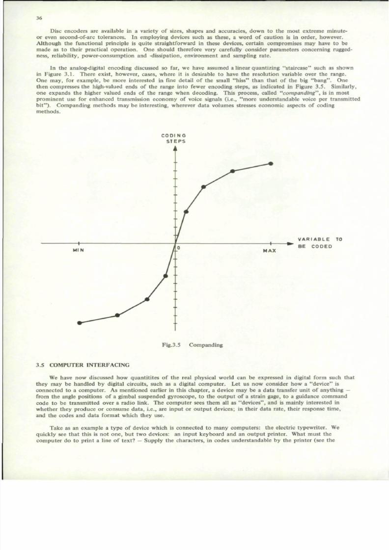
7/29/2019 Agard-Ag-183(Principles of Avionics Computer Systems)
http://slidepdf.com/reader/full/agard-ag-183principles-of-avionics-computer-systems 44/192
36
Disc encoders are available in a variety of sizes, shapes and accuracies, down to the most extreme minute-or even second-of-arc tolerances. In employing devices such as these , a word of caution is in order, however.Although the functional principle is quite straightforward in these devices, certain compromises may have to bemade as to their practical op eratio n. One should therefore very carefully con sider parameters concerning ruggedness, reliability, power-consumption and -dissipation, environment and sampling rate.
In th e analog-digital encoding discussed so far, we have assumed a linear quan tizing "stair case " such as shownin Figure 3.1 . There ex ist, however, cases, where it is desirable to have the resolu tion variable over the range.One may, for example, be more interested in fine detail of the small "hiss " than that of the big "bang ". Onethen compresses the high-valued ends of the range into fewer encoding step s, as indicated in Figure 3.5 . Similarly,one expands the higher valued ends of the range when decoding. This process, called "com pand ing", is in mostprominent use for enhanced transmission economy of voice signals (i.e., "more understandable voice per transmittedbit") . Companding metho ds may be interesting, wherever data volumes stresses economic aspects of codingmethods.
C O D I N G
S T E P S
V A R I A B L E TO
B E C O D E D
Fig.3.5 Companding
3.5 COMPUTER INTERFACING
We have now discussed how quantitites of the real physical world can be expressed in digital form such thatthey may be handled by digital circuits, such as a digital com puter. Let us now consider how a "dev ice" isconnected to a comp uter. As mentioned earlier in this chapter, a device may be a data transfer unit of anything —from the angle positions of a gimbal suspended gyroscope, to the output of a strain gage, to a guidance commandcode to be transm itted over a radio link. The com puter sees them all as "de vices ", and is mainly interested inwhether they produce or consume data, i.e., are input or output devices; in their data rate, their response time,
and the codes and data format which they use.
Take as an example a type of device which is connected to many com puters: the electric typewriter. Wequickly see that this is not on e, bu t two devices: an input k eyboard and an outpu t printer. What must thecomp uter do to print a line of text? - Supply the characters, in codes understandable by the printer (see the

7/29/2019 Agard-Ag-183(Principles of Avionics Computer Systems)
http://slidepdf.com/reader/full/agard-ag-183principles-of-avionics-computer-systems 45/192
37
following section), one by one: letters, punctuations, carriage returns, line feeds — all in the right order. The speedin which the codes arrive, is, however, limited by the movement of mechanical parts, and the printer can only acceptthe next character when the former has been duly recorded . Synchro nization information is therefore needed by
the computer. Even more accentuated is this need by the keyboard. Many factors determine the rate at which the
keys are pressed — from contact bounce in switches to operator's skill and "thinking time".
Let us first establish certain features common to all devices. To the computer, the outside world is a numberof "peripheral devices", Figure 3.6. In some form, the communication to a device may be split up into data, device
code or actuating signal, and status or "sync" signal. How general in nature each of these will be depended on thecomplexity of the entire system, as well as the individual device.
C O M P U T E R
i D A T A
DEVICEACODE__.
^STATUS
\ j
P E RI P HE RA L
D E V I C E
POSSIBLE
FURTHER
COMMUNICATION
Fig.3.6 Com puter communication with outside world
The device code from the computer, activates the device, for example to print the character, whose code is
simultaneously presented on the data lines. A "ready" signal is raised by the device whenever it can accept a new
data-set (e.g., character) and lowered when it is "bu sy" . Note that this concept is quite general, and applies equallywell to input and output devices. The parameters important to the computer are:
- Input or output.
- Data format and code (word-length, binary, BCD, "ASCII"*, Gray, etc.).
— Transfer time (how long must data and device code be available for transfer between computer and device).
— Transfer (how often, max, min, and average, will transfer be required).
Let us return for a moment to the printer. The computer puts a character code on the data lines and the
"printer" — code on the device lines. The printer will accept the character, and lower its "ready" signal. The
computer thereby knows it has to wait for the "ready" before it can present the next character. This, however,will take several tens of milliseconds, even for a fast printer, in which time the computer might have donethousands of useful computer operations. It cannot a priori know exactly how many, though. To utilize computer
time efficiently, while communicating with peripheral devices at the speed they require is a fundamental problem,to which there exist a number of solutions. We shall discuss the main principles in this section. Note that the
speed requirement is normally set by the peripheral device, either for economic reasons ("to keep the printermoving") or for other reasons associated with the system. I.e., a sampling process must be carried out by a clock'sprecision or an operator command must be obeyed with a minimum response time, etc.
The simple solution to let the computer wait is rarely acceptable. The main synchronization methods can be
listed as follows in order of rising complexity and data rare capacity.
(a) Let the computer wait.
(b) Compute for some "safe" maximum time, then wait.
(c) Keep com puting, but sample the status of the device at intervals, and attend to it whenever it is ready.
(d) Keep computing, but let the peripheral device "interrupt" for attention.
(e) Let the device communicate directly with the computer memory without direct program control.
"American Standard Code for Information Exchange", dominating in use for coding alphanumerical test (letters, digits, punctuation,etc.).

7/29/2019 Agard-Ag-183(Principles of Avionics Computer Systems)
http://slidepdf.com/reader/full/agard-ag-183principles-of-avionics-computer-systems 46/192
38
Methods a—d, with variations, are known as 10-controlled ("In-Out"-) communication with peripheral devices.Method e, is known as "direct memo ry access" (DMA). 10-control requires the computer to issue a specific "1 0-instru ction" such as typically "transfer con tents of the accumulator to output device numb er d". Somehow , theremust be a synchronizing mechanism, and that may be done in various ways, e.g., method s a—d. Methods a or bwould halt the com puter temp orarily, until the device became ready. Method c would require a variation of the10-instruction permitting a conditional jump in the computer program depending on the status of the device.Method d requ ires specific status change signals from p eripheral devices to be able to "generate in terr up ts". Aninterrupt means that the program, necessarily retaining information which permits the computer to resume where it
left off after the interrupt has been attended to. Many variations of interrup ts and interrupt handling capabilitiesare available, and have been a field of much fruitful ingenuity over the years. No te, however, that all of these 10-metho ds, interrupt o r not, still defend their place for some application. No method is "pe rfect" for all applications.Our further discussion will be limited to a few points of special interest.
Note that none of the 10-control methods mentioned can ensure perfect efficiency for both computer and 10-device in a general case. One or both norm ally has to waste some of its time . Even a soph isticated in terru ptsystem will be wasteful to some exten t. Assume that a com puie r has only one 10-device. Data can then be transferred w ith maxim um efficiency. Such a case is, however, rare. Probab ly there w ould be at least two devices, sayone for input and one for ou tpu t. We then have the wicked possibility of coinciding interrup ts. This problem iseasy to deal with. However, the com puter m ust somehow both determine which one of several possible interruptsit has received, and if it receives coinciding inter rup ts it must be determined which to attend to first. Althoughcoincidence may occur infrequently, the system must always be prepared to hand le that situation. In practical
systems this uses up part of the computer's capacity, and makes it impossible to guarantee immediate response toall interrupts. In more extrem e cases, the com puter spends most of its time shifting between interrupt priority levels,thus impairing the efficiency w ith which it can deal with other task s. An even more serious problem is the logicimplications of multiple interrupts from the program mer's point of view. This problem is dealt with in further d epthin another chapter.
Direct memory access (DMA) is a good solution in cases, where the data transfer rate is so high that too muchcom puter capacity would be taken away for administration by 10-control. A computer basically consists of (oneor more) central computing unit(s) and m emory (m emories). Instructions and data are stored in memory andfetched from memory via a memory access channel, where a computer word of some given word length, say 16 bits,is transferred, one at a time. A DMA-channel is anothe r subscriber on the mem ory, which may "ste al" m emorycycles while the comp uter is kept w aiting. The com puter need not " wo rry ", i.e., no logical provision need be m adein the program, but its operation will be delayed by the "stolen" memory cycles.
The device communicating over a DMA-channel needs to provide a memory address together with its "memorycycle requ est", and it must provide or accept the data-word, as the case may be input or ou tpu t. The program willcommunicate with peripheral devices by finding or placing, respectively the data in "10-tables".
This method of communication is of first interest where large amounts of data, i.e., many computer words,are to be transferred . This will then take place as a block transfer, in which the DMA-device has the capability tobe started at some table beginning location and to increment addresses for each transferred word up to an endinglocation of the block or table. The com plete block transfer will typically be started (and perhaps be stopped o r"signed o f f ) by "conv ention al" 10-instructions, where the "da ta" typically specify beginning location and blocklength, rather than actual data. The DM A-control will then appear as an 10-device. "R ead y" and "b us y" signalwill apply to the com plete block transfer. In addition, other status information such as address coun t, errors,abnormal conditions, etc., will be needed by the administrative programs, and can be sampled while the transfer isin progress.
Real time is a parameter, im portant in many control systems. A clock is then arranged as a peripheral device.E.g., time of day may be read in coded form. The clock may be arranged to gene rate interru pt at specified times,for example every millisecond.
3.6 DATA TRANSMISSION
Data can be transmitted from one place to another over lines or radio channels similarly to voice communications. Direct transmission of analog data has very limited application for a num ber of reasons. In the more generalcase, data are transm itted in digital form, which again is mo dulated upon som e carrier. The mo st interesting factis, perhaps that it is technically within the state-of-the-art to transmit data at any conceivably demanded rate (sayup to a few Gegabits per second), and to m ake sure of its correctness to any specified degree. The m ore extreme
demands may, of course, rule themselves out for economic reasons if nothing else.
In a limited te xt, such as this, we shall again limit our discussion to the mo st central and im por tant facts. Adata transmission channel has the task to accept binary words of a certain word length and rate at one end, andpresent them a t the other with only a specified am oun t of loss, error and delay. The necessary fun ctions, some of

7/29/2019 Agard-Ag-183(Principles of Avionics Computer Systems)
http://slidepdf.com/reader/full/agard-ag-183principles-of-avionics-computer-systems 47/192
39
which are optiona l, are depicted in Figure 3.7: a stream of words are buffered, may be converted to anoth er code ,and transformed to a stream of binary digits occurring at a certain bit rate. These are modulated on to some carriersystem which is used on the actual transmission medium, which may typically be lines, radio links or laser beams.For example, the output of the modulator may be a signal confined to the spectral and other requirementsstandardized for a telephone channe l. At the o ther end th e signal is dem odulate d, etc ., by a similar, inverse chainof functional units.
Let us look at the functions in some more detail: buffer circuits are necessary to accomm odate the power
levels and timing requirements of the sending and receiving devices to those of the transmission channel for aparallel word. Various interfaces as well as many param eters are being standardized b y several standardizing bo dies,such as for exam ple: CCITT , CEPT, ISO, and are used extensively for many stand ard data transmission tasks.
"Recorder" and "decoder", is here a generalized name for the following functions:
— Adding special bit patterns for "frame sync", necessary to recover the original word pattern in a continuousbit stream.
— Adapting the bit rate and possible synchronization deficiencies of the transmission channel to the actual rateof incoming and outgoing words.
— Adding redundancy to the incoming information bits, for detection and correction of errors introduced bynoise, etc., in the transmission channel.
— Encryption.
These functions m ay take on a variety of forms. They may also be included in the sending and receivingdevices, rather than th e transmission channel. The ir purpose is to achieve perfect transmission of data over a non-perfect transmission medium , or more accurately : to obtain a specified m aximum error rate in spite of noise anddistortion. (Encryption is used for protection of data so that they cannot be understood by unauthorized p arties).
Speed adaption is required if the transmission channel is built for a specified fixed bit rate higher than thatrequired. Seen from the receiving end, there must be a safe way of identifying each bit as distinct from the previousand the nex t bit. Fur the r, there m ust be a safe way of determining which bit is which, so that one can re-edit thebit stream into words. Fu rthe r, one needs to identify each word, etc. Without going into detail, let us note , thatthese requirem ents will take their share of the capacity of the transmission chann el. To meet these requirem entswith satisfactory efficiency, performanc e and simplicity is and has been the field of much igenious design. Let us
note that specified bit rate of transmission has different meaning depending on where in the transmission channelwe refer to.
A more subtle speed adaption may be required in some transmission systems which apply intermediate storageand /or time division mu ltiplexing: if various parts of the transmission system em ploys non-synchronized clocks,"slippa ge" may occur. Circuits can be included w hich automatically supervise the information stream and eliminatesloss of transmitted inform ation by "stuffing ". Tha t is: some redun dant w ords are included at regular intervals atthe transmitting end. These are removed, or more are inserted along stations of the transm itting path, to ensurethat slippage does not cause loss of "paying" information.
Some circuits treat data as "messages" of limited, fixed or variable length. In complex nets of many sta tions,messages are "sw itche d" i.e., routed t o their destinations. Sometimes "store and forwa rd" technique s are applied.
Error detection and co rrection may be achieved by special coding. This simplest technique is "pa rity checkin g".In each word, an extra bit is included. It is made one or zero depending on the oth er bits of the word such thatthe tota l numb er of ones in a word is odd ("odd pa rity ";. All received w ords are checked to see if they have oddparity . If they do not, an error must have occurred in transmission. If the received parity is correct one has someassurance that there were no transmission error. A double error, may, however, go und etecte d. There is thereforea finite probability of und etected errors. To reduce this proba bility, one might include more "chec k-bits ". Bythus choosing the degree of redundancy and the pattern in which it is employed, any specified probability ofunde tected errors can be met in a given noise environm ent. "Cyclic block cod ing" is a generalized m ethod ofhigh redundancy coding. It is easy to implement, can be applied to any degree of protec tion, and has well predictable performance if the noise characteristics are known.
It is also possible to employ redundant coding to achieve error correction, i.e., transmission errors can beautomatically co rrected at the receiving end. The simplest con cept is perhaps to send each part of the message
three times, and determine the correct part of the message three times, and determine the correct part by "majorityvoting" . More sophisticated and efficient me thods are also available. Comm on to all is that the y do not give 100%prote ction , but again: by choosing the degree of redunda ncy and th e pattern in which it is emp loyed, any specifiedprotection may be achieved, in terms of probabilities.

7/29/2019 Agard-Ag-183(Principles of Avionics Computer Systems)
http://slidepdf.com/reader/full/agard-ag-183principles-of-avionics-computer-systems 48/192
40
DATAIN
BUFFERRECODER
SERIA-
LIZER
B I T
STREAM
M O D U LATOR
TRANMITTING
SITE
TRANSMISSION
MEDIUM
D E
M O D U
LATOR
BIT
STREAM
SERIAL
TO
PARALLEL
D E
CODERERRORDETECTOR
BUFFERDATA
OUT
RECEIVINGSITE
Fig.3.7 Data transmission channel

7/29/2019 Agard-Ag-183(Principles of Avionics Computer Systems)
http://slidepdf.com/reader/full/agard-ag-183principles-of-avionics-computer-systems 49/192
41
In general, error correction is much more costly redundancy-wise than error detec tion. An interesting andpractical compromise if two way communication is available is error detection, and retransmission of erroneousmessages upon demand.
It should not be forgotten that many a pplications will tolerate a certain amo unt of errors. In any case, theactual need for error free transmission should be properly analyzed before going to an error detection or errorcorrection system. Well established theory is available for proper qu antitative design of error protecting systemsin data transmission.
Similarly the data may be encry pted, th at is: special coding and decoding devices may be included to make theinformation unintelligible to a third party listening in the transmission channel.
Standards are especially im portan t in data transmission system s. Many standardizing bodies such as ISO,CCITT, CCIR, CEPT and others have issued standards and recommendations for numerous variables from bit rates,to alphanumeric codes, from time division multiplexing, to modem interfacing.
3.7 THE PROGRA MM ERS VIEW
Although it is simple in principle to connect a peripheral device to a computer, there are numerous detailswhich must be logically correct and efficiently managed for every information transfer. These details, which fall
into the main categories coding, timing, editing and management belong to the more tedious and critical logicproblem s in com puter system design. Some of the problems are common to all devices, but every device has itsown special requirements.
As a Programmer, one may have written a routine to compute a function and store the results in a table inmem ory. These num bers can probably best be stored in the format used by the arithme tic unit of the com puter.If I want a graphical display of the function and a printed table, the internal table must be converted into two newand diffferent formats: one to suit the digital to analog conversion parts of the graphical display device and oneto suit the alphanumeric code used by the printing device. Furth er, some scaling, editing and possibly some interpolation and some rearrangement of data will be required to make efficient use of the capabilities of the devices andto give the results a neat and easily understan dable a ppearanc e. Fur ther, it will be useful to also produce someadditional information such as axes, "tick m arks ", and headings. Since the two devices are separate and ind epend entthey might be running concurrently, while the central computer at the same time performs these conversion, editingand other functions. To do this, however, some management is necessary.
To avoid having to go into every little detail every time, certain of these functions are usually programmedonce and for all in such a way that they may be used for various applications. These various programs, termed"device drivers", interrupt handlers", translating and conversion routines, etc., are often combined with other systemprograms into a common program called the "operating system".
Ideally, the system programs of a computer will permit the programmer only to worry about the detailswhich are specific to the task at hand, to let him specify his desires easily, and to allow maximum utilization ofthe devices which are employed by the system. These problems are discussed in depth in anoth er ch apter.
Selected Reading for Further Detail
General logic, number representations:
1. Richards, R.K. Digital Design, Wiley 197 1.
AD- and DA-conversion:
2. Hoeschele, D.F ., Jr Analog-to-Digital Digital-to-Analog Conversion Techn iques, Wiley 1968.
Delta modulation, companding:
3. Belts, J.A. Signal Processing, Modu lation and Noise, English Universities' Press, Londo n 1970.
Data transmission, error protection:
4. Martin, J. Teleprocessing Netw ork organiz ation, Prentice-Hall, 1970.

7/29/2019 Agard-Ag-183(Principles of Avionics Computer Systems)
http://slidepdf.com/reader/full/agard-ag-183principles-of-avionics-computer-systems 50/192
4 :
CHAPTER 4
OPTIMIZATION
Yngvar Lun dh
4.1 THE OPTIMIZATION PROBLEM
An avionics com pute r system , as well as all othe r engineering job s, needs optimiza tion. In our case we maysomewhat more specifically define the process as:
For a given task to seek a device which on one hand solves the problem with adequate performance and
reliability, and on the other hand requires minimum space, weight, power and cost in some combination.
First let us realize, that this optimization process may be different d epending on who does it: the systemdesigner or the com puter designer. The entire system's point of view, again may or may no t permit complete freedom in sharing the different parts of the jobs between computers, special units, hardware, software and so on.
For our discussion let us assume that the solution is not constrained by limited choice of standard sizes, shapesand forms or by choices made by someone else, past history or bad for tune . Although such ideal situations rarelyoccur, let us still try to seek out the ideal trade-offs in order to come closer to them.
One little guide may be deduced already from this little introd ucto ry con sidera tion: it is a virtue in itself inthis world full of imperfections and compromise, that a complicated system consists of individual, small sub-unitswhich have readily defined functions and connections to their environments, such that they may be replaced,improved and perhaps even removed with minimum effect on the rest of the system.
For a computer based system to have adequate performance, will as a minimum mean that all the logic andcomputational functions required can be done — in the time demanded by the system requirements. The designereasily gets into a vicious circle here, because he does not necessarily know all the logic and arithmetic functionsrequired until he has the bulk of the design work already do ne. But long before then he must have assumed ormade a num ber of choices. These may later prove to be far from o ptimal. For exam ple, if the choice were betweencomputers A and B, he may have to actually program many functions before he knows if the computing capacityis adeq uate or grossly over-estimated. To have a too large comp uter sitting idle during much of its time rarelyimproves the system in any way, bu t may be a burden . Clearly, therefore metho ds for making the right choice earlyare in demand.
It will always be necessary to break a com plicated system do wn into smaller parts for various purposes. Eachpar t, then can be defined and specified, and be optimized individually during the design process. As more details
become clear during this process, conflicts may arise because of unforeseen details, and there will be choices to bemade which involve more than on e part. Often these choices are such that simplification of one part means complication of anothe r. During development on e has a dynamic situation , some decisions are easy to change later, someare difficult. Since often various parts are to be made by different groups of people, companies or establishments,contractual and various, perhaps irrational viewpoints often tend to remove further optimization from the strictlytechnical level. This can easily lead to a sub-optimal solu tion, and it may be regarded as part of good systemplanning to be aware of this feature of the practical world and to seek the solutions which are the least prone tonon-tech nical optim ization . Witho ut trying to offer further general guidelines, let us be allowed to offer somepieces of experience which have proved useful.
Partitioning of the system is extremely im portan t. It is more im portant that the interfaces between parts aresimple, functionally logical, well definable and well defined than that the total sum of all parts are an absoluteminimum . We are here referring to th e partitioning done o n an early planning stage of a system being developed.
Design jobs to be done by people are highly dependent not only on their competence but also on their motivation. It is, therefore definitely contributing to a good solution if partitioning bo th of system fun ctions and ofdevelopment jobs to be done can be made with this in mind. The best criterion for this is often the partitioningwhich minimizes the need for communication between people (not the commu nication, but the need for it). Amongother things, this implies that the size of each task be such that it can be managed by one man who is master of allthe problems on this level, and who may safely refer problems on other levels to other people.

7/29/2019 Agard-Ag-183(Principles of Avionics Computer Systems)
http://slidepdf.com/reader/full/agard-ag-183principles-of-avionics-computer-systems 51/192
43
Let us not go further into management considerations, but only note that various decisions on the technicallevel can not be seen isolated from how the detailed development of technical solutions are to be undertaken, if areally optimal solution is to be expected in the end.
4.2 IMPORTANT PARAMETERS
Let us turn now to some specific important parameters which are useful to identify and consider in optimiza
tion of a computer based system.
Logic speed is a "technological fac tor", which characterizes logic circuits. It is measured in m aximum ("clo ck" )rate at which one can accept pulses, for example to be counted. One for example talks of "30 M Hz-logic". Anotheruseful measure is logic stage delay, i.e., the time from the input signals are presented to a single gate circuit untilthe gate produces its final outp ut. Typical value is several nanoseconds.
Comp uting speed is a very important factor, which unfortun ately is difficult to measure exactly. It will havedifferent meaning depending on the com puter. One measure is the num ber of machine instructions w hich can beexecuted per second, or the instruction rat e. However, execution time is normally different for different instructio ns.An average may be used, but this approximation is application dependent.
Machine instructions are also, of course, different from one machine to an other - some do more useful work
per instruction than others.
It is therefore almost impossible, and inconsistent with the continuous movement in the state of the art, todefine a universal measure of computing speed. After considering these factors instruction rate and instructionpower (of which word length is one, very coarse, indication), the next thing to do, is to actually program sometypical, preferably frequently occurring functions, and find out what the comp utation time is. One functionfrequently used for comparison is the com putation time for calculating the square root of a num ber. Oth er functionsmay, of course, be more relevant for specific applications.
Memory capacity is another important factor, which is easier to characterize and measure.
The principal parameters are
— Size; N words of B bits each.
— Access time; time from the address is specified until the desired word content is produced for read operations.
— Cycle time; minimum time taken per successive operation.
Note that
(access time) < (cycle time)
These times may be different for read and write operatio ns.
"Random access" means "access time is independent of the address and the order in which addresses arecalled". Certain mem ory type s are serial in some way , which mean that the access time is much shorter when thewords are accessed one by one in a given order. If an arbitrary word is sough t, one has to wait for an arbitrary
part of a "multicylce" or "revo lution". This is referred to as non-random access type of organization. The accesstime for such memories is a function of several variables and of the way in which the memory is used, rather thana single figure.
Since speed is desirable, but hard to come by, larger memory systems normally consist of a combination offast and slow me mory. Some mass memories are often arranged to be able to transfer large blocks of many wo rdsrather than single words.
Volatility is anoth er quality of importance for many applica tions: the danger of losing memory con tent inthe case of power failure o r abnormal con ditions. A continuum of properties are available in different types ofmemory such as: "completely volatile", "power pro tected ", "read mos tly", "programmable read only ", "readonly", etc.
Communication capacity is the efficiency with which the computer can exchange data with peripheral devices,that is data transfer rate, flexibility of synchronization (direct memory access, interrupt, etc.) and adaptability tovarious situations and equipment co nfigurations. This concerns bot h hardware and software facilities.
Survivability and reliability und er normal and adverse cond itions are imp ortan t param eters. Many avionicssystems are required to op erate , perhaps at reduced performance, with defective pa rts. This, of course, then is arequirement of fundamental importance to the system design, specification and evaluation.

7/29/2019 Agard-Ag-183(Principles of Avionics Computer Systems)
http://slidepdf.com/reader/full/agard-ag-183principles-of-avionics-computer-systems 52/192
44
Modularity, i.e., partitioning into replaceable parts, is normally a desirable quality.
Physical parameters of primary importance are: volume, weight, power dissipation. In addition num erousparameters associated with environmental resistivity are important, such as operating temperature range, vibrationand shock, electrical noise, radiation, etc.
Programming complexity is a feature of the utmo st impo rtance for comp uter systems in general. For anavionics system, the computer programs, even all "application programs" must be considered to be part of the
system. When a system is com plete and working, one might therefore con sider it immaterial how much tro ublewent into com pleting the programs. However, programs as well as hardware normally need maintenance. Changein data characteristics during use may reveal shortcomings or errors. Accomm odating additional facilities into thesystem, expansions and improv ements, all require the programs to be re-examined and changed. The com pleteprogram m ust therefore n ot be a mysterious, unreadable tape or jungle of symbols. It should be specified,described, explained and broken down into functional parts at least as thoroughly as the hardware parts of thesystem . Fu rthe r, there should be available facilities for making changes. This means that new or changed program scan be written and tested using the same methods (language, editing, testing) as those used orginally.
These are the main parameters which characterize a com puter based system. Unfo rtunately, m ost of them aredifficult to measure. This fact may often place too much weight on the few qua ntities which can be measured ,overlooking other importan t factors, and thereby missing better solutions. Were it not for this unfortu nate situation,optimization would be more straightforward, certain — and less of an art.
A comprehensive study of a number of important and representative computers have been made by C.G.Belland A.Newell in a voluminous book : "Co mp uter Structures: Readings and Exam ples" (McGraw-Hill 1971). Theyhave introduced unified methods for describing the computer organization and instruction coding, and they haveidentified sets of "para me ters" or "dimen sions" : which are all imp ortant for characterizing com puters. All thesedimensions can then he said to form a large "comp uter sp ace". They define the main dimensions of this space to be:
— Logic technology (tubes, transistors, IC's, . . .),
— Word size (number of bits),
— Addresses per instruction,
— Structure (organization and interconnection of main functional units),
— Memory access (random, cyclic, linear, . . . ),
— Memory concurrency (multiprogramming, interrupt handling, . . .),— Processor concurrency (parallel, serial, multiple instruction streams, . . .).
The complexity and large amount of information collected in that book throws much needed light on manysides of comp uter techno logy and how to appreciate co mp uters. It also, however, serves to illustrate the fact thatthere is no really simple and universal way to describe and compare all aspects of computers.
4.3 TYPICAL TRADE-OFF SITUATIONS
In this section we shall identify some important trade-offs which are useful to know when seeking a way outof the multitude of possible configurations which a computer based system may be given.
Speed com plexity are related in a clear cut and often surprisingly general way. Let us look at two exam ples:
(1) To perform 200 000 a dditions per second we can use one adder which can do its job in 5 microseconds.If such an adder were not available, or had an unattractive price, we might consider a slower one, say a10 microsecond unit. Almost certainly we could replace the fast one by two slow ones plus some extracircuitry to distribute the load between them.
(2) If a binary full adder needs 10 nanoseconds to add tw o bits and 5 ns to propagate the carry, a 16 bitparallel adder would consist of 16 such circuits and might require 10 + 5.16 = 90 nano second s foradding two 16 bit numbers, plus perhaps another 20 nanoseconds to set the result into a flip-flop register.If we, however, did not require this high speed, we could do the job bit by bit, i.e., in series instead ofparallel. Using the same full adder circuit, we would on ly require one instead of sixteen . Instead of110 ns, the total add time might be (10 + 5 + 20) ns per bit, i.e., 35.16 = 560 ns for 16 bits.
Thes e, slightly simplified, examples are typical of the general rule that speed m ay be traded for simp licity: Afaster unit can be simpler or a more complex unit can be slower to achieve a specified processing capacity.
Instruction repertoire - speed is just a specific example of the same rule. Let us look at another exam ple.Com puter A (big) has a multiply-instruction in its repertoire, compu ter B (small) has not. B has a standard

7/29/2019 Agard-Ag-183(Principles of Avionics Computer Systems)
http://slidepdf.com/reader/full/agard-ag-183principles-of-avionics-computer-systems 53/192
45
subro utine, however, which employs B's simple instructions such as add and shift to do the same job . The interestingthing now is "how long does multiplication take", not "which one has hardware multiply" or "what is the instructionrate"
Instructions - speed - memory size are really three factors which determine computing capacity separatelyand can be traded against each othe r. To com pute a sine function one can for example
(a) have an instruction to produce it directly, by a complicated arithmetic unit; or
(b) do a subrou tine using simpler instructions, more time (assuming the same logic speed in the arithm eticunit) and more memory; or
(c) do a table look-up , using extremely sim ple, if any arithm etic, very little time and a large amou nt ofmemory.
Accuracy - word length is, of course, unlimited in a digital comp uter. However, if one needs more than 16 bitaccuracy in a 16-bit machine , one needs to program m ultiple word length operations . This takes much more thantwice the time for double precision than for single, etc . Tha t is probably still the most economical if the needarises infrequently. If, on the oth er hand, higher precision is in frequent dem and, a longer word length may be acheaper alternative than a higher instruction rate.
All these factors are interrelated and depen dent in ways which are difficult to describe in a general, application
indepe nden t way. The most impo rtant fact is, however, that they are interd epen den t. It is for example meaningless(or at best a very coarse approximation) to say that slow processes need slow computers, meaning low instructionrate. It is the total processing capacity which must be matched to the task.
Another matter is that there usually are constraints which limit the free choice along the entire scale of tachparam eter. In real time systems, this may be illustrated by the two factors throug hput and response time. "Rea ltime data processing" in general means that: Any backlog of data accumulated in the processor never increasesbeyond a given maximum value for a specified data th roug hpu t which may be m aintained inde finitely. Responsetime is: the time taken for a data value entering the data process to influence the ou tput. The required responsetime may require a fast com puter rath er than a slow but c omplicated one. For exam ple, our previous suggestionwith the two 10-microsecond adders would be unacceptable if the result were needed in 50 microseconds (i.e., thedelay of 10 us could not be tolerated). So although the two adders might cope with the throughpu t, the choicethen would be constrained by the response time requirement.
Hardware-software is another trade-off, which really is a different name for the instruction-speed-mem ory size,which was already me ntione d. This name, however, can also refer to the trade-off betw een built in functions andfunctions which must be reconsidered when programming a new situatio n. A Fourier transform , may be done by aspecial function unit (hardw are) or a special subro utine (softw are). Similarly a compu ter may have an interru pthandling subroutine (sofware), or much of the logic such as priority, save-unsave, etc., may be implemented byspecial devices (hardw are). Such functions may be solved equally well by hardware or software. In a com pute roffered as a compon ent there are, however, great variations in which and how many such standard functions havebeen included at all, or must be done by the system designer and application programmer. This trade-off may n otbe important for the performance, but to flexibility and design changes, as well as complexity of the system designjob.
Reliability-complexity is a less well defined relationsh ip. With a given technology , i.e., type of circuit components and tolerances, the simplest, i.e., smallest number of components will be the most reliable if the organization
is non-redundant.
If the reliability of the computer thus obtained is too small (mean time between failures too short), it couldbe improved by duplicating the computer, i.e., to have another doing the same job, and some equipment or programsto decide if one compu ter fails and then disconnect it. Even more reliability b oth per dollar and per liter, etc. , andtotally , may be achieved using other, more sophisticated redundan cy m ethod s. Theory and methods for design offault tolerant com puters are in cons tant developme nt. Con ceptually, however, they tend to be difficult. They aretherefore expen sive, and normally n ot justified on a limited econom ic basis. The econo mic aspects of reliabilityare normally covered by conservative use of tolerances and well proven technological methods.
There are, however, many cases especially in avionics systems, where this is used to its fullest extent, and stillis insufficient. Extreme statistical reliability is for example required during missions of long duration witho utpossibility of repair. Special techniques and quan titative m ethods for assuring necessary reliability m ust then be
emplo yed. In other cases hazards may occur against which it would be impossible to make the system resistant.This is true with many military systems, and equipment which is to operate in less well known environments."Graceful deg radatio n" is then desirable. The system may be designed to operate for example in emergency modesperhaps at reduced performance when parts have been disabled. The trade-off here is between survivability andcomplexity.

7/29/2019 Agard-Ag-183(Principles of Avionics Computer Systems)
http://slidepdf.com/reader/full/agard-ag-183principles-of-avionics-computer-systems 54/192
46
Another type of trade-off in a highly dynamic field such as ours concerns credibility of new and exotic devices.Our aim is at new systems to be developed rath er than at old proven o nes. However, we normally want new ideasimplemented early to beat "t he co mp etition" in some form or another. It is therefore of interest to consider whichsolution can be implem ented first. In an existing system it is frequently easy to poin t out not only sho rtcoming s,but how things ought to have been . In the new system to be developed , howev er, we are typically "going to emp loysome extremely attractive new techniqu es" which com pletely eliminate the old shortcomings. To foresee theinevitable new shortcomings of the new system is desirable, but not au toma tic. Good system p artitioning hasalready been men tiond , and may more specifically m ore easily perm it correction of m istakes along the way. It is
also no coincidence that small computers are normally earlier to utilize new technological progress than big ones:they take shorter time to develop. Therefore, they are often competitive in com putations per dollar or per literalthough the small compu ter would tend to loose against the big one using the same technology. Concepts whichcan be implemented rapidly, therefore have a virtue by themselves. For tasks other than theoretical:
An old-fashioned and primitive, but working device is infinitely more efficient and useful than a modemsophisticated one which only exists in theory.
4.4 METHODS OF DETERMINING ADEQUACY
The only method which can be recommeded, other than actually trying out a complete system is simulation.
A compu ter based system consists of co m pu ter s) and peripheral devices. The latter must be specified bytheir performance data and the job they are to do . The comp uter is to be designed, chosen and /or programmed.After this has been done, most of the work is finished. It is of great interest to be able to make estimates longbefore th en. No general way to achieve this can be offered. Let us, how ever, describe one attractive way ofdesigning dedicated computer based systems, and leave it to the reader how he might make use of it in this case.
We are to have a com pute r doing a specified job as part of an avionics system . We will then first assume acomp uter X. We will then know its instruction rep ertoire, possible standard su broutines, 10-functions, etc., andhow long each takes to execute.
First we write a simulator for the new com puter as a programme on another comp uter S (preferably in a highlevel language, which may even be com pute r indep end ent). We then w rite the application p rograms for the assumedcomp uter X. Furth er, we write a mo nitor program to be run on comp uter S, simulating whatever is required of th eenvironm ent, and monitoring the (simulated) performance of X. It runs the X-computer simulator program and
keeps accoun t of how long each "ope ratio n" takens and how often it is performed. "O pera tion" may refer tomachine instruction, subroutine calls, times through specific program loops, etc.
We may thus simulate our whole problem, or critical parts of it using computer S only, not even needing toacquire com puter X. This procedure allows us to do the following imp ortant investigations.
We may make sure that processing capacity is adeq uate . Fo r a real time system that typically means that th etime available, e.g., within a sampling interval is sufficient for running throug h all necessary program loops by wayof all possible path s. Similarly we will find out if the processing capacity is grossly oversized. We can in oth erwords, determine how the computer meets the demand for processing capacity.
We may investigate alternate programming methods, algorithms concerning their consumption of computercapacity as well as their performance.
We may identify the m ost critical parts of the comp uter limiting its capacity for our application . This isdone by examining the accounts of the monitor for which instructions or operations are most frequently used andhow time is spen t. This is especially useful both in seeking and evaluating alternate algo rithms as well as studyingthe value of optiona l features. The m ethod is equally useful for considering a com pute r to be bou ght or an entirelynew one to be developed.
These procedures may further be applied not only in determining the adequacy of computer X, but incomp aring com pu ter X, Y, Z while seeking the optim um s olutio n. The facilities offered by a simulation such asthis are in many respects greater from the point of view of optimization than it would be to actually havecomputers X, Y and Z available, since computer S is simultaneously used for obtaining all these useful statistics.It is also generally a fast method because it eliminates many non-essential experimental difficulties.
The application programs which where thus used during simulation are immediately ready to be used in the
actual computer later on.
To simulate the entire system may be useful. Without going to that e xtrem e, however, it may still relieve thesystems designer of many uncertainties if he can only identify and simulate the more critical points at an early stage.This both enables him to make better estimates, and forces him at an early stage to actively pursue the criticalpoints, which in general is good design practice.

7/29/2019 Agard-Ag-183(Principles of Avionics Computer Systems)
http://slidepdf.com/reader/full/agard-ag-183principles-of-avionics-computer-systems 55/192
47
CHAPTER 5
SYSTEMS AND SYSTEM DESIGN(Software Design in Computer Based Systems)
C.S.E. Phillips
5.1 INTRODUCTION
This chapter is not concerned with the writing of programs by individuals for their own purposes, nor withcom putation per se. It is concerned w ith the produ ction of software by professional teams for com puter co ntrolledsystems dedicated to some special purpose. Such systems are essentially software based, usually real time and , as is
now realized, much more complex than they may appear to the outsider. Recent experience has shown that thesesystems have taken much longer to produce and have been less successful in operation than had been expected at thetime of their conc eption. In particular, the amou nt of software needed and the difficulty of its produ ction has beenseverely underestimated. This was mainly due to the assumption tha t the individualistic, problem solving approachappropriate to programmers as computer users is adequate for system building; in other words, the lack of systemsthinking and a systems approach.
5.2 SYSTEMS
A system is best defined as a whole consisting of a set of interacting constituents, where the whole is differentfrom or transcends the sum of the con stituen ts. This definition is so all-embracing that it is not surprising thesubject should carry a high flown subjective air and be regarded at times as of little practical use. In mod em timesthe systems viewpoint has permeated organization theory (the interacting parts being men), but if we think of the
organizational problems faced by the builders of the Pyramids the study of systems could be said to predate science.Nevertheless, the real impact of systems thinking has come quite recently, in sociology, politics, economics, managemen t, etc., as well as in most b ranches of science and engineering. There are natural system s (physical and biological),man-made systems (political, economic, engineering), designed systems (avionic, computer, social Utopian), slowlyevolving systems (political, economic), systems which are self regulatory, controllable, goal-seeking, adaptive, learning,growing, decaying, e tc , and those w hich are no t There is a small but growing interest in the study of systemsconce pts in general both for its intrinsic interest and for its practical importance as the basis for system design. Incomputer based systems particularly, system problems are beginning to overshadow the problems of engineeringtechnique.
In the past most systems have been regarded as "closed" i.e., having no inputs from or outputs to an environme nt. Such systems, for example the planetary system , systems of mathematics and physics, ninete enth centuryeconomic models, etc., can be recognized by their lack of purpose (any purpose other than their own existence)
and are conventionally subjects of scientific or engineering work. The interaction s between th e constitu ents andthe internal behavior of a closed system can be expressed often mathematically in great detail as casual relationships.Physical scientists and engineers are trained in and are mo stly interested in closed systems. Thus scientists analyzenatural systems whose purpose is not their concern, whilst engineers tend to pay only lip service to purpose sincethey are primarily concerned with making things. White and Tauber1 in their book Systems Analysis are mainlyconcerned with closed systems and trace their extensive and highly successful development from the Renaissanceonwards.
An open system has an environment and it was biologists who first pointed out that their systems affected andwere affected by the environment3. Open systems which are characterized by "pu rpo se" and "hierarchy " arenever an end in themselves and require Ideological (goal directed) rathe r than causal explan ations. For exam ple,in answer to the question why does the apple fall to the grou nd? we may see this episode as belonging to a closedgravitational system and reply because the weight exceeded the strength of the stalk. If the gravitational system is
regarded as a sub-system of an ecological system we answer so as to produc e more trees . We have only to think of"man in his environment", the topical interest in world social and ecological matters, the falling interest in "science"(i.e., regarded as closed system thinking), modern attitudes to organizational and planning techniques and finally thevery recent attitude towards computers (that they are rarely an end in themselves) to realize how widespread opensystem thinking has become. In fact the term system is now synonym ous with open system.

7/29/2019 Agard-Ag-183(Principles of Avionics Computer Systems)
http://slidepdf.com/reader/full/agard-ag-183principles-of-avionics-computer-systems 56/192
48
Systems whose interactin g parts are themselves systems are by definition hierarchical - thus we speak of subsystems and sub-sub-systems and the purpose of a sub-system is to perform some function for the system (whichitself may be part of a super-system). For a very crude example, in the following connec ted, "b otto m -up " sequenceof system levels — solid state physics, microcircuits, computer architecture, software, navigation system, aircraft, airdefence, economics, foreign policy, national politics, world objectives, each can be regarded as an open system whichmakes use of and depends on the (previous) sub-system and whose purpose is to serve and thus affect the behaviorof the (successive) super-system.
Turning to the class of man-made systems (more precisely, sub-systems) which can be designed or re-designedover a short time period, that is those which primarily concern engineers and computer scientists, one might reasonably conclud e from this that th e design of a new system w ould take other levels into accou nt. Here we reveal a majorsystem design prob lem. Difficult as it som etimes is for a designer to coopera te with designers of other sub-systemsat the same level, coo peratio n b etween designers at different levels is often poo r or even negative. The reasons forthis are partly psychological (individualistic attitudes, etc.) and partly mutual incomprehension (different disciplines).It is difficult for designers to give and take respo nsibility for the design of even the im mediate system level aboveand below without creating difficult problems of cooperation.
More imp orta nt, perh aps, there is a further inheren t difficulty with the design of an open system w hich arisesfrom the fact that it is defined Ideolo gically.
It seems to be a general characteristic of open systems that, though they clearly have a purpose of some kind,
on careful exam ination that p urpo se is revealed as uncertain or ambiguou s and th at the difficulty of developing anew system is more connected with this ambiguity and uncertainty of purpose than from its inherent complexity.This may account for the fact that it seems to be easier to put two men on the moon than to develop an air trafficcontrol system or reorganize a local authority. The ambiguity is often unrecognized in that the "p urp ose " may bemultiple (i.e., a "balanced" set of objectives), understood differently with different people, or changing with time.Fu rtherm ore the purp ose of a system can only be described in terms of a system at a higher hierarchic level. AsLangefors7 has said, all systems are pote ntially sub-systems. But what is the pu rpose of this higher level system?Here we touch on a paradox, that a system to be developed can be fully understood only in terms of (theoretically)all higher levels of system imaginable; yet work can start only if the purpose of the system is taken for granted,(e.g., two men on th e mo on). Unfortunately it is all too easy to conceptually d ose a system, that is, to assume itspurpose is self evident; the problem in practice is to open it up again. The solution of this problem of iterationbetween hierarchic levels belongs to the realm of system design methodology.
5.3 SYSTEM DESIGN METHODOLOGY
Recent experience9 in the design of complex computer-based systems has shown that such systems have takenmuch longer to produce and have been less successful in operation than had been expected at the time of theirconcep tion. In particular the amoun t of software needed has been severely underestimated.
A more general understanding of Systems and Systems thinking would have avoided such errors and disappointments. On the othe r hand it must be admitted th at at present the study of systems concepts offers wisdom andund erstandin g rather than panaceas for the design of complex sys tems. Nevertheless there is a growing interest inthe application of these concepts and theories to system design m ethodology . Here we must point out the importantdifference bo th between system s and engineering and between individual and team work . In term s of man-years,the most efficient way of developing for example a hardware or software system is for the engineer or programmerto "close" it (i.e., to define its operational purpose himself), to develop it where possible from standard available
sub-systems, and to design and construct it himself. He would evolve his own instinctive ad hoc methodology,using such principles as seemed app rop riate, based on his experience and ab ility. Where an organization (system ofinteracting m en) is conc erned , such an app roach is no t possible as its "intelligen ce" is of relatively low o rder. It isgenerally agreed that the rate of development is not proportionately increased when larger teams are used.
We must recognize that computer-based real time systems are particularly complex because of the softwareinvolved. It is no t that the elemen tal sub-programs are any more comp lex than the oth er parts of the system suchas the sensors and other peripheral units; nor is it connected with the computing hardware, which can often beregarded as a given "off -the -sh elf sub-system of the software. The problem arises partly b ecause of the lack ofstandardized sub-program s and any standard w ay of defining and intercon necting th em . It is for this reason thatindividual programming work is so much more productive than team work. Ano ther problem is the comm unicationbetween p rogram mers and higher level system designers as already men tione d. It is unlikely tha t prog rammerswould be capable of, or even be permitted to, dominate and determine the design of, for example, an avionic
com pute r system. Fo r the future, on e must assume that avionics system designers will have a much b etter trainingin computer science.
What methods should we use to develop computer-based real time systems? Boguslaw4, in an amusing analogybetween the design of social Utopias and computer-based systems, has proposed four main system design ideologies.Firstly, formal methods in which the proposed system is planned and defined in exhaustive detail, secondly,

7/29/2019 Agard-Ag-183(Principles of Avionics Computer Systems)
http://slidepdf.com/reader/full/agard-ag-183principles-of-avionics-computer-systems 57/192
49
heuristic methods using "good" (but vague) principles, thirdly the use of available (standard) sub-systems andfourthly, the "ad h oc " or unplanned approach. Clearly, the last method has been well tried, will always be popularand, let us admit it, more interesting for the individual designer.
One formal method under investigation at the moment attempts to borrow the Syntax directed techniques ofcompiler writers by defining systems in syntactic terms 11 -12 . Unfo rtunately , formal methods tend to be over-rigidand obscure in practice. As far as general principles are conce rned, those currently in favor are the " top do wn "(in which the details are considered first) and the principle of iteration.
A particular methodology of software development combines these principles with the idea of organizedevaluation - the "three prototype m ethod "10 . Here a system would "evo lve" by being developed three times(rather than once), the first time to clarify its "purpose", the second to find out how to make it and the third time,how to make an engineered pr odu ct. The philosophy behind this idea is that iteration between hierarchic levels isimpracticable during the development of a software system, so that definite time slots are arranged for this purposebetween the development of three essentially closed systems. A research modelling or prefeasibility stage might alsobe required before work on the first prototype was begun.
The "available sub un its " approach is much used in traditional engineering. In compu ting systems the m ethodis exemplified by the idea of comp uter packages in which standard programs of sets of programs are used. Suchpackages are beginning to be used in A.D.P. systems where standard operations occur, but not yet for real-timesystems. Many project managers seem unaware that a new program is not made like hardw are, but must be invented
before it can be produced. The software should therefore be their first concern - not something to be left till later.
It is difficult to draw any definite conclusions abou t the trend in system design methodo logy. The subject isvery complex, embracing on the one hand project management (another system in itself) and organization theoryand on the other, systems of docu me ntation (ano ther difficult and neglected subje ct). With a very small, highcalibre team, ad hoc methods may still be best, but it is more usual now to evolve more formal, if arbitrary, methods.In general, the principle of iteration is thought to be particularly important, i.e., cycling through "top-down" to"b ott om -up ", but it is difficult to achieve this in practice where the teams are large. Un doub tedly, bette r meth odsof controlling iterative system development using computer aided documentation of the time varying managerial,design and programming data will be introduced in the future, but human problems will be more resistant tochange. System designers largely concern themselves with their own problems and often tend to regard "sub system desigems" on the one hand as short-sighted and incompetent and "super-system designers" on the other asignorant and vacillatory. This problem is not necessarily alleviated when there is a one to one correspon dencebetween system levels and an organizational hierarchy.
We are mainly concerned in computer based systems with iterations between levels confined to closely alliedsden tific and technical disciplines. As far as broade r ma tters such as defence systems as a whole are concerned theproblem is even more difficult. Present administrative and managerial meth ods have been developed for the procurement of "equipment" i.e., well-defined, "closed" systems, so that inter-disciplinary iterations over many levelsinvolving "ultim ate " users would require a revolutionary change in attitudes . This problem is bette r understood inthe social sdences than in computing or engineering.
5.4 PROGRAMS AS SYSTEMS
Let us imagine that we are given the task of writing a real time program given suitable hardware andprogramming facilities including a good, high level language. Taking a sy stems viewpoint we know that we ou ght
to interact at least one level up and dow n. The level down involves taking part in the design or choice of theprogramming language and the comp uter configuration. Let us ignore this aspect by assuming that previousexperience has confirmed our agreement with the cho ice. The level up concerns operational des criptions which wetake part in, similarly we idealistically expect that operation (e.g., avionic system) designers help to write the program.As a result of this cooperation, iterations of analysis and synthesis can take place which will result in an expandedand modified operational description and a first attempt at a written program.
We note immediately that the typical designer of an operational avionics system has little experience of realtime programming. The typical computer programm er probably knows little about avionics. How are they tocomm unicate with each other? This is an example of the interdisciplinary problem already mentiond. Moreover,it is a fact that the higher the hierarchic system level the less precise and "scientific" the subject matter becomes.It is fair to say that there is as yet no organized and agreed body of knowledge about the specification and thewriting of such programs. It would be helpful therefore if we could interpose additional conc eptual system levels
between the application designer and the program w riter. There appears to be two possible levels where moreformal techniques can be introduced, the functional specification and its translation into networks of process anddata areas.
The first of these levels concerns problems of system specification and "m an-machine in terac tion ". There isa need here for a technique which clearly, rigorously and unambiguously describes the user requirements of the

7/29/2019 Agard-Ag-183(Principles of Avionics Computer Systems)
http://slidepdf.com/reader/full/agard-ag-183principles-of-avionics-computer-systems 58/192
50
system as far as possible in hierarchic term s. Working from these descriptions a program designer would be thenable to draw up a high level program design in which all the main data areas, programs and their interactions arespecified. The aim should be to provide a time ordered description of all the operation s undertak en by bo th manand machine for each of the functions un dertak en by the system. The description w ould make clear all branchesin a chain of operatio ns and also those places where parallel ope ration s occur. The object would be to enforce astructured description of the system which is more precise than plain English and which is, in principle at least,hardware independent.
There are two main techniq ues which offer po ssibilities. One is to "pr og ram " each function in plain English,with an accompanying flow ch art. Each "prog ram " would contain operations to be performed manually as well bythe com puter. In one scheme of this type 10 , modifications to conventional flow charts have been made to indicateparallel operations and to distinguish conditional branches occurring within the computer from those occurringmanu ally. It would be possible to simulate such a "p rog ram " so as to investigate the proposed system from afunctional point of view.
A more "mathematical" technique is to describe the system syntactically 10 '11 '12 . This meth od is essentiallyhierarchical in that each definition is expanded into sub-definitions and is inspired by the methods of defining andconstructing com puter languages. It goes beyond a textual description of the operational-requirement in that it"hold s the hope of being a more rigorous way of developing real-time program s". However there is some dou btwhether such a rigid technique will be suitable for the rather diffuse, parallel running functions which must beexpressed at this sytem level or whether operational system designers will be able to master such a sophisticated
technique.
When those parts of the functional description which must be performed by the computer are separately defined,the conversion of these into run ning com pu ter program s has still to be accom plished. At this lower level it ispreferable to think in broader terms than either detailed programming (coding) or computing hardware. The programnetwork 10 is one possible techniq ue. It is based on the con cept th at the fun ctions are performed by a set ofparallel-running, coope rating processes whose interac tions consist of data transfer. A process is defined as a more orless con tinuo us conversion of data from o ne form to anoth er. At this stage we are not concerned with the meansby which such a conversion is to be achieved so that a process is best thought of as a "virtual computer" or aprogram to be written.
The particular system concept of dividing real time programs into processes and data areas and the diagrammatictechnique described below which arises from it is not universally used, but is gaining acceptance, primarilybecause it is an easy method of specifying and comprehending computer programs.
Diagrammatic techniques which illustrate the continuous running of sub-programs in parallel are analagous tothe block diagrams of electronic engineering or analog compu ting. The im portance of such diagrams, which shouldnot be confused with flow diagrams, has been recognized only slowly partly because, as mentioned previously,programs have been regarded as algorithms rather than systems and partly because there is no agreed basicphilosophy of real time computing.
Having described how the functions of the system can be achieved by means of interacting conceptualprocesses, we now need to consider in turn how these processes should be cons truc ted. Let us assume we havedrawn up a network of processes which is connected with a manual and physical environment by means of dataand signal transfer. Our remaining problem is therefore twofo ld: to write a program w hich will run on a machinefor each process and to provide a means of activating processes. One of the major conc eptual and practicaldifficulties in computing arises from the fact that these process programs must share common computing hardware,
which allows only one process, or part of a process, to run at a time. Of course, multi-computer systems existwhich share the work crudely b ut it would be impractical and inefficient to use a com pu ter for each process.Similarly one could envisage multi-processor systems where particular processes are allocated to "processors", butthe present trend toward "reconfigurable" multi-processors for higher reliability implies no such allocative distinction.
We therefore arrive at a situation where the processes are to be implemented using a common set of hardware,the com puter; they share access to a data base containing current information about the environmen t, and in somesituation s share code to perform their actions. Th us, detailed know ledge of the interfaces, both in terms of messagespassing between processes and also via shared data base areas together with information about shared code is vitalto specifying the program design. Such information can be conveyed by means of a matrix of interconn ections ormore conveniently by the netwo rk diagram. Such a network of processes does not include those manual and non-manual processes external to the computer, but in early development it is good practice to add these in order todescribe and simulate the total system.
An individual process is "co nstr uc ted" by w riting a program. A process algorithm is therefore described inplain English or at a more detailed level by its program te xt o r alternatively by a mixtu re of the tw o. A singleactivation of a process is called a "task ". We are now concerned with two qu estions, how to control these tasksand how to write the programs. Owing to hardware limitations, tasks must run sequentially and must share

7/29/2019 Agard-Ag-183(Principles of Avionics Computer Systems)
http://slidepdf.com/reader/full/agard-ag-183principles-of-avionics-computer-systems 59/192
51
hardware resources with all other tasks. This problem is overcome by developing a separate programming systemcalled the "real time operating system", which conceptually creates from the (usually single) processor of thecomputer many virtual processors to run processes.
The real time software system can therefore be divided into two main sub-systems, one concerned with theapplication tasks to be carried out and the other with the means by which tasks are scheduled, and allocated tocompu ting resources such as stores, computing time and peripheral equip men t. Leaving the application programsaside for the moment, we have seen that the real time operating system, which is often rather confusingly described
as "system software" or even "software", transforms the com puting machine into a "virtual mach ine". (In thefuture one can expect computer designers to respond to this reflection on their equipment by designing hardwaremore closely matched to programmers requirements, once these are better understood.)
A real time operating system does not normally interact with ordinary "user" programmers, as in a conventionalcomp uting installation. It is therefore simpler in this sense than the large multi-purpose conventional operatingsystems. (The adjectives "multi-p urpo se" and "general purp ose " when applied to the word "sy ste m" should causealarm and it is interesting to observe that the complexity of conventional operating systems is widely believed tobe out of proportion to the benefits they bring.) A real time operating system has more limited objectives, buteven here there is a need for a be tter conc eptual understan ding and an underlying philosophy. The idea of attaininga more modular and extensible system (i.e., by dividing into sub-systems) is gaining ground, but the "ad hoc"approach still dom inates. The main difficulty is one of definition. For example a recent trend is to regard a realtime operating system as consisting of primitive routines called a "kernel" or "nucleus" handling operating system
tasks and application tasks indistinguishably. This latter view point presuppo ses a more clearly defined concep t of atask and a particular philosophy of real time programming. It should be emphasized th at it is often difficult todifferentiate between the actual tasks to be performed and such matters as the interactions between tasks, avoiding,detecting and controlling fault situations, arranging for easy alterations off and, perhaps, on line, avoiding "deadlyembraces" (where two tasks prevent each other from using resources) and, in a message based system, "back up"where local overload spreads to all message channels.
Whether or not the time-shared processes include operating system programs which look like applicationprograms, that is irrespective of the theory behind the division into the two sub-systems, each sub-system requiresthe cons truction of processes, i.e., the writing of programs. It is possible at this stage to regard this work as anindepende nt activity, i.e., merely a case of developing an algorithm to a specification. However these processes areoften complicated or ill defined and the corresponding programs when written reveal inadequacies in the upper leveldesign. It is a valuable con ception therefore to sub-divide each process into sub-processes and data areas in exactlythe same way and for exactly the same reason as the system was divided into processes. The difference here is that
sub-process and data area interconnections involve the data structures and sub-routine calls of the programminglanguage used. In the case of an Algol type of language such as Coral 66, Reference 13, sub-processes can bedescribed by procedures, and data area connection s are defined and restricted by the syntax . A process can thereforebe envisaged as continuing private data indistinguishable at that level of description from pure program, which at alevel below is revealed as the linkage between sub-processes. It is an obvious extension upwards for a language toinclude within its synta x, built-in ways of handling parallel process inter-commu nication as well. The exact req uirements for such an invasion of operating system functions is not well understood as yet so that such language mustbe regarded as experimental.
Having sub-divided processes hierarchically in this manner we arrive at elemental processes which are programmedpreferably as procedures in high level language (or sub-routines in assembly co de). These lowest level procedures willprobably be relatively simple, communicating with data either directly or via the parameter mechanism provided bythe language. The extent to which procedures can be nested depends on the language used. Some procedures will
be common so that a diagram will show a hierarchical network of procedures rath er than a simple tree. Conn ectionswith data will be complex so that it may well prove useful to store network information on a central computingfacility as part of the docum entatio n system - togethe r with program t ex t.
The efficiency of the running programs depends on the language design in relation to the computer architectureand the quality of the compiler. A small numb er of particularly fundamen tal pieces of program may be written as"m ac ros " which expand i nto sho rt pieces of machine cod e. Viewing real time programs as systems, these macros aretechnically the lowest level elements. However in a modem (high level language) com puter based system the "pr oc ed ure "should be regarded as the fundamental element which drives the system. The com puter based system is then moreaccurately described as a software based system, since translation of software into hardware actions is purely automatic.
5.5 FUNCTIONAL SYSTEM APPROACH
We have referred to the need for a technique which bridges the gap between the functional description of thesoftware sub-system and the complex detailing of programs which are ultimately the means by which these functionsare achieved. What is really required for the software is a number of parallel continually running data p rocessingoperations, but we are forced by the inherent nature of digital computers to construct each data processing operation

7/29/2019 Agard-Ag-183(Principles of Avionics Computer Systems)
http://slidepdf.com/reader/full/agard-ag-183principles-of-avionics-computer-systems 60/192
52
in terms of an ordered seq uence of steps - as the word "p rog ram " implies. We are also forced to simulate theparallel running of these operations by time sharing computer hardware.
We are not therefore concerned in what follows with programs as such — as algorithms expressed in programming language or flow diagrams — since these are the details of con structio n of a process. We are attacking themain problem in software produ ction - deciding what programs are to be written. The actual writing of a programis usually a relatively straightforward job.
The principle behind the particular method to be outlined is that the software is regarded as a system whoseconstituents are
(1) data ; and
(2) processes
and where the interactions between constituents are
(1) reading and writing of data by processes; and
(2) interactions between processes.
The interactions between processes at an upper system level are
(1) interrupts,
(2) system calls (intera ction s with some form of real time operating system ),aand
(3) sequential activations.
The system is hierarchical in the sense that processes contain (or in programming terminology "call") sub-processes,leading to
(4) hierarchical interac tions between processes.
Although these entities and relationships can be set down in matrix form, a diagram is a more useful tool forthis purpose, and such diagrams are referred to as "program networks" or "Phillips diagrams".
5.6 PURPOSE OF PROGRAMMING NETWORK DIAGRAMS
The programming network 2 4 '2 7 is a two-dimensional, diagrammatic, information processing, language primarilyintended to simplify the description of large programs particularly those to be written by a number of programmers(although it can be used to describe any program). The most imp ortant time to draw up programming netw orksis at the systems analysis stage, i.e., after the system requirements have been clearly established, (by means offunctional specifications for exam ple). Program netwo rks are useful for:
(1) Program design,
(2) Program interfacing and integration,
(3) Assisting management in understanding,
(4) Monitoring progress,
(5) Easing program and modification and maintenance,
(6) Instructing new recruits,(7) Documentation
(8) Program size and time estimation.
Data and Processes
The programming network consists essentially of two entities, data (represented by rectangles and processes(represented by circles) together with lines which show intercomm unication between these two entities. Thereading of data by processes and the writing of data into data areas by processes is represented by simple unbrokenlines. The distinction between data input by a process or data output from a process is indicated by arrowheads.The nam es of data areas and of processes are written into th e rectangles and circles. Simple examples are given inFigure 5.1.
5.7 DATA RECTANGLES
Data rectangles can be used to represen t either files, lists, buffers, array s, tables, identifiers, etc. or the words,characters, bits, etc. of peripheral sources (keyboards, input typewriters, registers, etc.) and sinks (displays, output

7/29/2019 Agard-Ag-183(Principles of Avionics Computer Systems)
http://slidepdf.com/reader/full/agard-ag-183principles-of-avionics-computer-systems 61/192
53
INPUT -^PROCESS OUTPUT
Fig.S. 1(a) A procedure named "process" reads data named "input" operates upon itand writes the result into data area named "output"
Note: In Coral 66 terms "in pu t" is a value and "o utp ut" is a location
UPDATE K - DATA
Fig.5.1(b) A procedure named "u pd ate " reads, transforms and writes backdata named "data"
Fig.S. 1(c) A procedure named "mix" reads "data" and "data 2", operates
on the data and writes the result into "data 3"

7/29/2019 Agard-Ag-183(Principles of Avionics Computer Systems)
http://slidepdf.com/reader/full/agard-ag-183principles-of-avionics-computer-systems 62/192
54
( NAM E )
NAME
*>s
V~>
v>
/
A
^ = >
-^wvwv-^
Process (program, procedure, sub-routine, macro, block, statement)
Data (source or sink)
Data flow
Program initiator implying temporary transfer of control (link, procedure
call)
Program initiator implying permanent transfer of control (jump, goto)
Program initiator implying the connection between two separately designedsystems (system call)
External (hardware) interrupt
Fig.S.2(a) Basic symbols
PUNCH
\//A
Peripheral device
(data source or
sink)
Hardware
nterrupt
generator "DARD,
Hardware data
source/sink and
interrupt generator
Stf Circular list or
buffer with input
and output pointers
r / ^ r r chain linked
~ y y ~ listOw
Program which for
some purposes may
be classed as data
-VParameterless procedure call
l/P
Procedure call with input
parameter(s)
O/P
A rProcedure call with out
parameters
ro/pi A rQ3D
Procedure call with input
and output parameters
^ %Parameterless system call
• ^
ITpl
System call with input
parameters)
Jk44thystem call with output
parameter(s)
V %m v
System call with input and
output parameters
datrocedure call when data areas
omitted (optional)
Fig.5.2(b) Variants of basic symbols

7/29/2019 Agard-Ag-183(Principles of Avionics Computer Systems)
http://slidepdf.com/reader/full/agard-ag-183principles-of-avionics-computer-systems 63/192
55
typew riters, registers, etc .). Each rectangle must contain an unambiguous and meaningful name (unabbreviated ifpossible) which is consistent throug hout th e doc um enta tion. If there are equivalent names or if a data area is brokendown elsewhere into elem ents, a comp lete index of names must also be provided. Cross-hatching of hardwa re datarectangles is recomm ended to distinguish them from software sources and sinks. Figures 5.2(a) and 5.2(b) showthe types of basic symbo ls used. Only simple arrowed lines may be connected to data areas.
Fig.S.3 Simple hierarchic program netwo rk
5.8 PROCESS CIRCLES
A process circle represen ts a function whose behavior is indepen dent of its activation. In programming term sthere must be only one entry poin t. Process circles can be used to represent proce dures, sub-routines, macros, coral66 blocks — even simple statem ents. Processes are usually activated by oth er processes, but they can also be activateddirectly by hardware (external inte rrup t). Processes should preferably be written as procedures (or macros) and aretherefore activated hierarchically by other proced ures. The external interrupt con nection between hardw are and
process is quite different from the data transfer betwe en hardw are and process and data areas are conceptuallypossible, but direct connections between one data area and other (i.e., without an intervening process) are neverallowed.
Types of process activation are illustrated in Figure 5.2(a). The distinction betwee n these forms is primarilya question of control, i.e., the place where control exists before activation and the place where control is passedafter the process terminates. As far as the process itself is conce rned, there is only one entry poin t. The behaviorof a called process is therefore independent of the calling process except insofar as it is modified by actual data.The four methods of activation of processes are:
(1) External activation (by hardware interru pt). Here contro l is temporarily transferred t o the process at atime determined by external hardware. Thus in practice control is transferred from an indeterminatepoint in an indeterminate process and on completion of the process or processes, control returns to the
interrupted process at the point of interruption.
(2) Sequential activation. In this case one process perman ently transfers contro l to ano ther. The last obeyedaction of the calling process must be a GOTO label (or jump) where the label is the name of the calledprocess. To avoid unnecessary distributio n of con trol, this form of activation should be avoided wherepossible.

7/29/2019 Agard-Ag-183(Principles of Avionics Computer Systems)
http://slidepdf.com/reader/full/agard-ag-183principles-of-avionics-computer-systems 64/192
56
(3) Nested (or hierarchical) activation. This is the procedure (or sub-rou tine) call, where one process, at apredetermined point, temporarily transfers control to another, control returning to the calling process atthe point of inter rup tion . Nested activation can also be used to represent the effect o f a Coral 66 (Algol)block . This form of activation is preferable to sequ ential since it expresses the hierarchical relationshipbetween processes.9 Input parameters may be passed to a sub-process which may subsequently returnanswers to the calling process (see Figure 5.2(b)).
(4) System activation . This form, which can often be om itted in diagrams, is used to represent the transfer
of control, at a predetermined point, from a process in one sub-system to a process in another subsystem , being coope rating, parallel acting, or separately designed. This form of activation wo uld be usedto describe the interaction between a program and a time-sharing operating system which handles morethan one program . However from the application p rogramm er's point of view, system activation m ightresemble any other procedure call.
5.9 EXAMPLE OF A SIMPLE HIERARCHIC PROGRAM NETWORK
Figure 5.3 shows a simple network which illustrates some of the above features. The diagram is not based onan actual program . The sequential activation symbol indicates that the program starts by activating process x . Theabsence of "S TO P" indicates that process x never end s. P rocess x can call processes y and z and process ycan call process z. The process circles can be arranged vertically in hierarchical order so that x is first level, y issecond level and z is third level (i.e., all calls are dow nw ard). It is no t intended that the diagram shou ld reflectany time sequences of events, i.e., the sequential activation symbol has not been used (apart from S TAR T). Thesupplementary documentation will carry the following information:
(1) An overall explan ation of the program in terms of x, y, z, fred, John and harry.
(2) The detailed da ta description s of fred, John and harry including an index of their sub-names which seemin the corresponding program texts, i.e.,
fred or parts of fred are referred to in x and y ,
john or parts of John are referred to in x, y and z ,
harry or parts of harry are referred to in y and z.
(3) A descriptio n of x, y and z in the following forms:
(a) In plain English,
(b) In outline language (e.g., pseud o cora l),
(c) In Coral 66 (or alternative language).
Note that program z will not refer to x or y ,
program y will refer to z only ,
program x will refer to y and z .
Although the network of Figure 5.3 is purely imaginary and the supplementary information is not available, it is nevertheless possible to describe the program in some detail. Process x has an internal loop or loops which ensure contin uityand this process updates fred using joh n data. It call two sub-processes y and z which use fixed constan ts called harry.Process y also uses fred. The purpose of y and z is to produce john data for x . The overall purpose of the networkis to provide fred d ata for outp ut or onward transm ission. This data is provided by x from john data , which is itselfprodu ced with the assistance of y or z or bo th. There is also some feed-back since sub-process y uses fred d ata.
Note that the number of times x calls y and z and y calls z (or even whether they are called at all) is notrevealed by the diagram since this depends on the algorithm concerned and the actual data.
5.10 HIERARCHY OF DIAGRAMS
A fully detailed n etwo rk diagram of a very large program will contain many rectangles and circles. To avoidcomplexity and to aid comprehension, large networks should be prescribed in hierarchical fashion such that eachdiagram is an expansion of part of a higher level, simplified diagram . Each diagram sho uld con tain less than abou t
twen ty or thirty rectang les and circles. No software system, even the largest, should therefo re requ ire more thanfive or six levels of docu me ntat ion , althoug h the nu mb er of lowest level diagrams would be qu ite large in this case.

7/29/2019 Agard-Ag-183(Principles of Avionics Computer Systems)
http://slidepdf.com/reader/full/agard-ag-183principles-of-avionics-computer-systems 65/192
57
LEVEL 1
LEVEL 2
LEVEL 3
LEVEL 4
LEVEL 5
LEVEL 6
Fig.S.4 Procedure call diagram
An hierarchical program network should be simplified by the following rule:
A sub-process activated by only one process can be regarded as a part of that process and so can be "eliminated'by merging it with the activating process, adding its activating arrows and data connections to the joint process.
Figure 5.5(a) shows the effect of following this rule on the netwo rk of Figure 5.3. Note th at process x (nowincluding y ) writes data in to the data area called joh n, but the three data areas canno t be omitted since they donot belong solely to any one process.
Figure 5.5(b) shows the result of a second simplification. It is now permitted to eliminate process z since itis now called by x only. Figure 5.5(c) shows a third simplification, permissible because all three data areas nowhave simple connections, "sam" being the name of all three data area.
Similarly, the ne twork of Figure 5.4 may be progressively simplified as shown in Figure 5.6. Firstly, we caneliminate b, e and g.
Note tha t process a must activate process f since it now includes process b .
The second simplification reduces the network to process a and process f and a third simplificationeliminates process f.
In general, any programming network can be progressively simplified in this manner except in "pathological"cases where every process is activated by more tha n on e othe r process. This only occurs when there are loopswhich means, in the case of nested activation, recursion.
Figure 5.7 shows a highest level network simplified to the point that it could be said to describe any real-timecomputer-based system. There are only two processes, one being software which operates on inputs from autom aticand keyboard sources and provides outpu t data both for auto ma tic control and human recognition. The human is
regarded as a "process" too complex to replace by software.

7/29/2019 Agard-Ag-183(Principles of Avionics Computer Systems)
http://slidepdf.com/reader/full/agard-ag-183principles-of-avionics-computer-systems 66/192
5H
START
Fig.5.5(a) First simplification
START
Fig.S.5(b) Second simplification
START
SAM • FRED & HARRY & JOHN
Fig.S.5(c) Third simplification

7/29/2019 Agard-Ag-183(Principles of Avionics Computer Systems)
http://slidepdf.com/reader/full/agard-ag-183principles-of-avionics-computer-systems 67/192
59
START
START
Fig.S.6(b) Second simplification
Fig.S.6(a) First simplification
ENVIRONMENT
DATA SOURCE
DISPLAYS
DATA SINKS
KEYBOARDS
Fig.5.7 Real-time computer-based systems

7/29/2019 Agard-Ag-183(Principles of Avionics Computer Systems)
http://slidepdf.com/reader/full/agard-ag-183principles-of-avionics-computer-systems 68/192
60
Fig.S .8(a) Simplified real-time system
TIME
SIMULATOR P2'ENVIRON
MENT
^SIMULATOR
INTERVAL
TIMER
am 1P1
H
jDATA
STfKtf p? u INPUT
DATA
Fig.S.8(b ) Simulation of system shown in Figure 5.8(a)
7/29/2019 Agard-Ag-183(Principles of Avionics Computer Systems)
http://slidepdf.com/reader/full/agard-ag-183principles-of-avionics-computer-systems 69/192
61
5.11 SIMULATION AND TESTING
Program design could be described as the expansion of a higher level program network into lower level detailedprogram networks. The prod uction stage could be described as the integration of lower level networks in to a higherlevel network. In the latte r stage, each progressively larger group of m odules (rectangles and circles) is surroundedby test modules culminating in the simulation of pheripheral hardw are. These test data and simulation programsshould also be described by program n etwork s. (See Figure 5.8.)
5.12 REAL TIME COMPUTER SYSTEMS
The majority of com puting is concerned with com putatio n for business or scientific purpos es. In theseapplications, a program is written which takes in some data, transforms the data into some other form and outputsit to a printer, plotte r or graphical display. Now adays, a computing service is set up to do this for a number ofindepen dent users who share the computing facilities. A user's individual results do not depend on the time takento perform their com puta tions , i.e. they are not "re al tim e" programs in the normal meaning. (In practice usersare very concerned about "turn around" time so that the term "real time" is often ambiguous.)
Continuously running within such a computer is a complex (and often very large) program which organisesthe separate computations (by "batching" or "multi-programming") and controls the various peripheral equipmentsemp loyed. Such a program , or rather, system of programs, is a general purpose "op erating syste m" . Although n ot
often thought of in such terms, an operating system is an example of a complex real-time software system dedicatedin this case to the special functions of a multi user computing service, namely the preparation and running of awide range of unknow n, individual, user programs. Since each "us er" is intentionally shielded from knowledge ofits inner workings, the operating system can well be regarded as an extension to the computer hardware and indeedmodem machines are being designed with this in mind, particularly for real-time applications.
The kind of real-time system with which we are concerned in this book differs markedly in certain respects.In the first place there are no user programs as such and so a wide range of back-up software is not normallyrequired. Secondly, there are additional peripheral equipm ents to control which are foreign to a conventionalcomp uting configuration. These control programs are usually regarded as part of the "applica tion pro gram s". Areal-time operating system therefore has fewer functions to perform than a general purpose operating system. In avery simple real-time system the operating system itself could virtually vanish as a separate entity, all its functionsbeing performed by the application programs themselves. Depending on the range of peripherals and the range of
functions to be performed by the system, the dedicated real-time system can be much simpler or more complexthan a conventional general purpose operating system. However, the complexity of most m odem real-time systemsnecessitates sub-division of the software in to smaller interacting sub-processes. It follows th at, unlike co nventionalprograms, real-time programs are more than merely algorithms and should be regarded as software systems.
Simpler types of real time on line systems would be fully automatic, but more complex systems permit manualintervention and supervision. Such systems also refer to and maintain a data base. The stored co nten ts of a realtime computer therefore consists of messages (communicating with the peripheral hardware), variables (the database) and "p ur e" program . During the early stage of building such a real time system the elem ental sub-programscan be regarded as independent computations so that a simplified form of computing service with support facilitiesfor compiling, editing, loading and testing is required. In general, such facilities have been poor in the past sincethe kind of computers used for dedicated systems tend to employ computer hardware not normally intended for ageneral computing service. There are two ways to overcome this difficulty. One is to provide a program development facility specially for the development of the system, the other is to develop the system on an existingdifferent facility. The latter m ethod is adequ ate for the early stages, but requires the programs to be easily transferable. When the final stages of integration of the sub-programs with the particular sensors take place, the generalcomp uting facility is inadequ ate and some means of testing and developme nt on the object m achine is essential. Asa result of past difficulties, much more attention is now being given to program development systems for real timecomputing projects.
A real time program consists or can be viewed as consisting of a number of interacting continuously runningsub-programs specially designed and dedicated to respond to and control input/output peripheral hardware for someoverall purpose. The concept of contin uous "p ara llel" running of programs is very imp ortant in real time systems.Of course, from a lower (machine code) level viewpoint, most computers in fact permit very little parallel operation;perhaps one central processing uni t, with a separate inp ut/o utp ut channel to the main store. At the lower microunit system level, all opera tions are sequential, unless there are separate stores. Some "mu lti proce ssor" com putershave separate stores and processing units, bu t these are still comparatively rare. The software p roblem arising from
the continuous running of programs "in parallel" are the main "techniques" difference between real-time systemsand ordinary user computations.
Fundamental to the parallel running of a set of cooperating processes is the means of interaction and thetechniques of activation of processes. Two m ain methods of activation are used, one (asynchronous) analogous toa postal service or in/out tray where signals are polled, the other (synchronous) analogous to a telephone in that

7/29/2019 Agard-Ag-183(Principles of Avionics Computer Systems)
http://slidepdf.com/reader/full/agard-ag-183principles-of-avionics-computer-systems 70/192
62
processes are interrupted . Interrup ts are used by ex ternal hardware to activate processes and these in turn interruptoth er processes. (It is interesting to n ote th at an inte rrup t, viewed at a lower sytem level as digital hardw are logic,is achieved by polling techniques nevertheless.)
In dedicated real-time computer systems the real-time response of the system (including the collection of subprograms) is vitally dependent on the particular requirements of the system and on the peripheral hardware employed.The system p rograms must take into account an environment determined response time. We can therefore distinguishtwo extremes in real time computing systems, those in which a slow response to manual intervention is merely
inconvenient and systems which would fail if a particular process (running of a sub-program) did not respond in timeto a peripheral hardware interrupt.
Important intermediate cases — also described as real time — are transaction processing, dedicated systemswhose function is to handle as much traffic as possible such as air traffic control (where overall response time isparticularly im po rtan t) or (less real time) air-line book ing. There is no doub t th at some of these distinction s aremore apparent than real and that the general trend in computing is towards more "real time" and to some extenttowards more dedicated systems. Possibly the true differences b etween com puter systems are connected more withobjectives such as response time, throughput, integrity, security, reliability, flexibility, adaptability etc., than withthe extent of real time operation.
5.13 HIERARCHICAL VIEWPOINT
Com plex systems are difficult to design and even to describe. As in other fields, a comm on descriptive technique is to start w ith the broad features and proceed in a series of steps of increasing detail tow ards elementalcom ponen ts. From such a "top -do wn " hierarchic systems viewpoint, our subject encompasses a number of distinctlevels.
At the highest level we have the user's view. Here the system is described functionally, i.e. in terms of wh atit can do . This description sho uld hopefully m atch the original ope rationa l requirem ents. The next level describeshow this is achieved in terms of manual operators and peripheral equipments viewed as sources and sinks of dataand con trol signals. The ap plications software occupies a specially im por tant role at this level as it is both the gluewhich holds everything together and th e central means by which the functions are carried out. For this reasonour systems are more accurately described as "software b ased" rather than "com pute r based". This software issub-divided ( perha ps thro ugh several sub-levels) into a large num ber of simple algorithms. Each algorithm is describedin a com pu ter language which is translated (by a special comp iler program ) into binary code. Here we arrive at a
description of the com puter. The binary code is interpreted by digital hardware into microprograms (sequentialsets of standard gating pulses) which control registers and store locations consisting of sets of semi-conductorpackages etc.
Of course, it would be unlikely that a new avionics project would involve simultaneous design at all theselevels. Nevertheless, indepen dent d evelopments cannot be ignored. As is common in systems work , designers atany one of these levels would prefer the lower level technology to be static and standardised since this simplifieshis pro blem , but on the othe r hand , technolog ical advances in lower levels offer him new possibilities. Someexamp les of these interactive problem s are: the effect of rapid technological advance in the sem i-cond uctorindustry on computer design, the matching of computer architecture and machine code to the growing need forbetter operating systems and high level language programming, the design of high level languages which arereasonably powerful, stable and standard, cover a range of users and yet make proper use of improved computerhardware and, perhaps most pressing for the avionics system designer, the relationship between programming and
system functions.
Until quite recently, it was generally believed to be essential to program real time systems in machine code.This created a very wide gulf between the user's view of the system as a set of operational functions and the assemblycode pro gram mer 's viewpoin t. This gulf is being bridged by growing realisation that a real time program must besub-divided in some way and that "efficient" assembly language programs can be bought at too great a price incomplexity.
The idea of using com pute rs to control eq uipm ent is comp aratively rece nt. At first, real-time programs werewritten in the individualistic style of conventional programming by programmers who often knew nothing ofengineering. Such programs were com prehens ible to the programm er only and led to obvious difficulties in developmen t and main tenan ce. When teams of program mers were involved this could lead to chaos. Now adays, the accenthas shifted from ingenuity and run-time efficiency towards comprehensibility and structure . The greater use of
diagrammatic documentation techniques and high level languages is part of this emphasis. Much remains to be donehere. A major impediment to the exploitation of the computer in engineering systems is the relative difficulty of"exp laining" the w orkings of a program com pared with the workings of complex hardware. It is as if electronicequipment could be studied, analysed and comprehended only in terms of detailed wiring diagrams.

7/29/2019 Agard-Ag-183(Principles of Avionics Computer Systems)
http://slidepdf.com/reader/full/agard-ag-183principles-of-avionics-computer-systems 71/192
63
As computer systems become less of a novelty, standardisation at lower levels, though restricting possibilities,offers the avionics system engineer fewer problems, assuming he is prepared to make use of existing technologies.For example, if he is con tent to use "off the sh e lf hardware and a standard language for real time programm ing,his basic elements are statem ents in com puter language. On the o ther han d, if he wishes to use a new com puterarchitec ture with novel instructions he may be forced to extend a standard language or even redesig n it. Similarlynew digital circuits may lend themselves to new computer hardware concepts.
1. White,Tauber,
REFERENCES
Systems Analysis, Saunders, 1969.
2.
3.
4.
5.
6.
7.
8.
9.
10.
11.
12.
13.
14.
15.
16.
17.
Emery, F.E., (Ed.)
Boguslaw, R.
Klir, G.T.
Mesarovic, M.D.e t a l .
Langefors, B.
De Greene, B.Kenyon (Ed.)
Naur (Ed.)Randell (Ed.)
-
Smith, M.H.A.
Hdy, M.H.M.
Woodward,et al.
Phillips, C.S.E.
Jackson, K.Prior, J.R.
Jackson, K.
Jackson, K.D.E.Buchan (Mrs)
Political Economy of Efficiency, Public Administration Review (USA) December 1966,also C.A.S. reprint No.2 HMSO.
Systems Thinking, Penguin, 1969.
The New Utopians — A Study of System Design and Social Change, Prentice Hall,1965.
An Approach to General Systems Theory, Van Nostrand, 1969.
Theory of Hierarchical, Multilevel, Systems, Academic Press, 1970.
Theoretical Analysis of Information Systems, Student Litteratur, 1966.
Systems Psychology, McGraw Hill Series in Management, 1970.
Software Engineering, p.47, 186, 204, NATO Publication 1969.
A Guide to the Development of Computer Based Systems, I.E.C.C.A. (P) 4/72,Royal Radar Establishment, MOD(PE).
Syntactic Description as a Means of Writing Computer Programs, A.S.W.E. Tech.Report TR-70-4, July 1970.
Syntax Analysis as an Aid to Sytem Design, RAF, Radio Introduction Unit,RIU/126/1/AIR June 1972.
Official Definition of Coral 66, HMSO 1970.
Networks for Real Time Programming, Computer Journal, Vol.10, No.l, May 1967.
(An early description of program networks as used for an automatic radar program.)
Debugging and Assessment of Control Programs for an Automatic Radar, ComputerJourn al, Vol.12, No .4, November 1969. (This article refers to program netwo rks forprogram testing and the simulation of peripheral hardware.)
An Experimental Operating System Written in a High Level Language, SoftwareSymposium on experiences with software in Computer Control Applications, Instituteof Measurement and Control, July 1969.
An Exercise in Program Design, Inter Establishment Committee on ComputerApp lications, IECCA(P) 6/71 M inistry of Defence (PE), UK. (A detailed des criptionof iterative top-down program design using networks extensively.)

7/29/2019 Agard-Ag-183(Principles of Avionics Computer Systems)
http://slidepdf.com/reader/full/agard-ag-183principles-of-avionics-computer-systems 72/192
64
CHAPTER 6
AVIONICS SYSTEM AR CHITECT URE
R.E.Wright
6 .1 INTRODUCTION
The sys tem arch i tect ' s task is to define and com bine a se t of hardware c om pon ents t o form a system whose
aggregate beha vior will me et the ope ration al requ irem ent for the syste m. Most avionic system s start with an
ope ration al requir em ent specified by a user or air-frame man ufac ture r. During the short history of aviation
there has been a growth of such operat iona l needs which have presented pro blems requir ing technical solut ions .
The re has also been an evolu tion of technolog ies to me et such needs. The tw o processes have to some ex ten tproceeded independent ly, becoming locked together whenever a major project requires implementat ion of hardware,
when i t i s the task of archi tectural des ign to meet operat ional requirements wi th components which meet the
sys tem cons tra ints and are wi thin the "State of the Art" .
This design process may well necessitate compromises in the operational requirement should a fully
com pliant solut ion be impract ical on technical or econo mic ground s . The avionic sys tem derives much from the
general develop men ts in sys tem engineering, but i s subject to part icular operat ion al requirem ents , phys ical
environ men ts and phys ical cons t ra ints which together jus t i fy a some what specia l ized approa ch.
The ope ration al requ irem ents imply some targ et for the reliabili ty of a system w hich is dictat ed by require
me nts for mission success and aircraft safety. The reliabili ty of a system can be expressed as the p roba bility
tha t it will perfo rm a specified m ission. Th e advent of digital com put ers in the 1950 's offered a potentia l
solution for an increasing operational need for precision in calculation and data transfers associated with navigation
and weap on delivery. How ever, the early digital com pu ters , based as they were on ther mio nic valve circuits ,could not survive or operate reliably in the relatively hostile thermal and mechanical environment of aircraft , nor
meet compet i t ively the phys ical cons t ra ints of s ize, weight and power cons um ption . The digita l com pute r was
thus initially confined to a groun d env iron me nt, and ground -based sy stems for the tracking and con trol of aircraft
were developed for both comm ercia l and mil i tary appl icat ions . This work included the development of data l inks
for the transmission of information in digital form over wire and radio links, both between ground sites and
ground-to-ai r .
A dramat ic change was brought about by the development of the t rans is tor , the magnet ic core-s tore , and
subsequent ly the integrated c i rcui t . These c ircui t techniques made i t feas ible to develop com pute r equipmen t for
airborn e use. The re are now available and in dev elop me nt a variety of digital com pu ters suitable for airborne
use. This chapter wi l l be concerned wi th the des ign of sys tems involving digi ta l computers as "components"
and the des ign methodology at that component level .
The early aerospace appl icat ions of digi ta l computers were subs tant ia l ly real - t ime, the computat ions being
performed us ing data s imul taneously acquired by the computer sys tem and the output from the sys tem being
used to give direc tions to op erat ors or control system s. Such systems existed very much in an analog world .
Input parameters (such as pressure, air-speed, aircraft heading) were continuous and usually presented to the
digital system in electrical analog form (i .e., dc voltages, syn chr o waveform s, etc.). The re has since been a
widening application of computers to cover management functions and signal-processing, some aspects of which
are not required to be performed s t r ic tly in " real - t im e" . At the same t ime t ransducers and other sys tems have
tende d to use digital techniq ues and provid e digital interfaces. How ever, the changes have been largely-
uncoordinated and often present the sys tem des igner wi th unnecessari ly complicated s i tuat ions .
A major cons idera tion in any ma nned aircraft is norm ally the safety of the crew and passengers. Analog
equipments , including radio equipment , have developed largely in an uncoordinated way, each new flying a id or
facili ty generating its own stand ards and equ ipm ent . Once established as a generally recognized facility individual
equipments have been developed by a process of evolution, but in general have been resistant to radical change.
Reasons for this include the undesirabili ty of changing displays, facili t ies and controls with which air crew have
beco me familiar and the cost of replacing existing in-service hard war e. New equip me nts have been accep ted b ut
have no t in general replaced the established facili t ies. This situatio n has prod uced an emba rrassing accu mu lation
of hard wa re, bu t the very duplicatio n and redu nda ncy of facili t ies has the attractio n to the op era tor of lessening

7/29/2019 Agard-Ag-183(Principles of Avionics Computer Systems)
http://slidepdf.com/reader/full/agard-ag-183principles-of-avionics-computer-systems 73/192
65
his dependence on any one system and the separation of systems minimizes the chance of propagating faultsfrom o ne system to anoth er. Digital techniques offer the possibility of combining some of these systems, butin doing so the system architect must endeavor to maintain the level of system integrity to which the user hasbecome accustomed.
The need for safety has led to the establishment of national agencies charged with the specification andcontrol of design standards for avionic system s, bo th military and civil. These bodies have produc ed a maze ofspecifications and procedures of which the system designer must have cognizance.
However, aviation is an international business and aircraft have to interact with ground-based facilities. Thishas led to the necessity for defining international standards for some system parameters (i.e., radio frequencyallocations) and equipm ents. Internation al military standards are usually agreed on an inter-government basis.Standards used in commercial aviation are also determined on an inter-government basis, but the operating airlines and the supplying avionics industries have formed associations and agencies (such as the Aerospace IndustriesAssociation, the Airlines Electronic Engineering Cou ncil. ARING and EURO CAE) with the aim of consolidatingopinion among the participants so that recommendations can be made to governmental bodies, airframe manufacturers and equipm ent supp liers. It can be extreme ly im portan t to the viability of a comm ercial system development that it is, or can be made to, fit within the framework of an internationally agreed specification.
Most aerospace digital compu ters use the binary numb er system. Each digit of a binary num ber can be oneof two states, '0' or ' 1 ' . Thus binary digits (or "bits") can be represented by a variety of physical devices that
have two distinct states, such as a switch that is either "on" or "off", or an amplifier output which is either"hard on " (low voltage) or "hard o f f (high voltage). A binary num ber or code of several digits forms a word.Words can be represented and transmitted electrically either as a time sequence of two levels of signal on asingle wire (serial operation) or as a set of simultaneous signals on a set of wires where each wire correspondsto a particular digit (parallel operation) or a combination of the two (serial-parallel).
The two-state nature of the signal enables thresholds to be defined such that appreciable degradation froman ideal signal can occur before a '0 ' or T state is incorrectly identified. Also drc uit s can be comp ounde d togive words of any length, so that once quantities have been converted into digital form it is possible to transmitand record them witho ut loss of accuracy, and to perform calculations with them to any desired precision. Thetrade-off is primarily betw een accuracy and hardw are. Typical word lengths for data in aero-space systems liebetween 12 and 24 bits. Com puter architectu re can include a range of the word lengths for both data andinstructions within the same computer.
The potential advantages of digital techniques at a system level include
— maintenance of accuracy of encoded data during manipulation,
— adequate computational precision and range of computing power (including use of special purposeprocessors, for example for spectral analysis)
— range of techniques for filtering and mixing of information (often without the time lags inherent inother approaches),
— automation of operating mode selection (reducing operator work-load),
— multi-plexing wire-sharing techniques (with consequent weight saving),
— data manipulation for communication with operators, crews and with other systems (making the use of
electronic displays feasible),
— possibility of storing library information, including flight manual and maps, in digital form in backing-storage (with a consequent weight saving and ease of up-dating and access),
— possibility of automatic fault detection and mechanizing failure survival,
— relative ease of system development and optimization (including the use of standard hardware andsoftware modules).
These advantages alone can make digital techniques essential to meet certain operational requirements, butthis is re-inforced by the con tinuing rapid developm ent of digital hardware techno logy. Developme nts in MOSand Bi-polar semi-conductor technology, thick-film, thin-film and printed circuit interconnection techniques,circuit encapsulation techniques, and electro-optical techniques have considerably widened the range of physical
environm ents and constra ints for which digital systems are practical. The predo min ant deve lopment is the so-called Large-Scale Integration technique(L.S.L), whereby some hundreds, even thousands, of digital circuits(e.g., gates) can be accomm odated on a single semi-conductor chip. This will make available an increasingrange of L.S.I, computers, memories, input-output multiplexers, etc., at significantly reduced quantity productionprices, so that the system architect will be able to make more liberal use of processors and memories, and beable to trade logical multiplexing of signals for wiring.

7/29/2019 Agard-Ag-183(Principles of Avionics Computer Systems)
http://slidepdf.com/reader/full/agard-ag-183principles-of-avionics-computer-systems 74/192
66
6.2 THE PRACTICAL APPROACH
As computer systems have continued to grow in complexity and sophistication it has become increasinglyrecognized that to design, analyze and document a system a number of levels of system description are necessary.These are not alternative descriptions, each level of description arises from the abstraction of the levels below it.
A hierarchy of levels can be identified, each level has associated with it distinct "language" for representing itscomponents, modes of combination and laws of behavior, albeit that the language may be expressed in both algebraicand graphical form. Bell and Newell1 identify four main levels: the circuit level; the logic level, the program minglevel, and th e Processor-Memo ry-Switch level (abbreviated to "PM S level"). It is with this PMS level that we aremainly concerned h ere. The system is conceived as an inter-con nected p rocessing system. The medium flowingthrough the connections is information, which can be measured in bits (or digits, characters, words, etc.). Thecomponents of the system are modules with information handling characteristics, including capacities and flowrates. The m ethodology of combining such com pone nts is system arch itecture. A definition of avionics systemsarchitecture is then : the combination of programmed processors, memories, switches, controls, comm unicationlinks, peripheral control/interface units, peripherals/transducers to perform a defined combination of operationaland control tasks, subject to partitioning and packaging dictated by the physical environment and requirements formaintenance. However the system architect m ust also be concerned with other levels of system description, thelower levels of programming and logic, and a rather ill-defined higher level concerned with the interaction of thecom puter system with other major systems, including possibly other c omp uter systems. This higher level of systemdescription (Major System Level) is necessary to determine the functional requirement of the computer system,
and will be considered further in another section.
The primary com ponen ts of PMS systems are defined by the set of operations they perform . In general theprimary comp onents consist of PMS structures of other compon ents. Primary comp onen ts interconnect with eachoth er at com mu nication s interfaces called "p or ts" . Here we will con tent o urselves with allocating single-letternames to primary com ponen ts and defining the roles the com ponen ts play in the system stru cture. A more detailednotation is given in Reference 1.
I-unit:
L-Iink:
M-memory:
S-switch:
T-transducer:
K-controI:
D-data operation:
P-processor:
A hierarchically organized information structure, in which each level consists of a numberof sub-units, all identically organ ized. The basic unit of inform ation is usually the bit.Inform ation rate, as measured at a port for instan ce, is the flow of I-units per unit time .
A component for transmitting I-units from the port of one component to the port ofano ther. A link perm itting transmission in one direction o nly is normally called a simplex
link, a link permitting transmission in both d irections is called " full" or " h a lf duplex ,depending on whether the transmission can take place simultaneously in both directionsor no t. The I-unit can be transmitted as a message block, of width determined by th enumber of basic units transmitted in parallel and of length the number of widths transmitted serially in one o pera tion. The ph ysical realization of links as wiring is oftentermed a "highway" or "bus".
A memory is a device for storing information, and indeed the term " sto re " is usedsyn ony mo usly. It consists of an array of locations in which I-units (i.e., wo rds) can bestore d. The two main oper ations are reading, in which an I-unit presented at an inputport to the memory is transferred to a location, and writing, in which the I-unit in thelocation is presented at an output port.The information defining the address of the location used may be supplied by the
com pon ent accessing the store information of some different com pon ent. The informationrate is the information in the stored I-unit times the operation-rate.
A potential m eans of linking sets of input and o utpu t com pone nts. It is actuated by anaddress which determines the sub-set of links to be connected.
A pair of connected links that have different I -units, or underlying carriers. Althou gh themeaning of the information transmitted is preserved the amount of information may notbe . At a higher level of PMS structure a transducer may represent an analog-to-digitalinterface.
A logical circuit that evokes operations in other components.
This component creates information,presents the result at an ouput.
It takes information as an input, operates on it, and
A component which operates with memories to perform a sequence of operations, includingdata-operations, on I-units from mem ory. Each operation sequence is determined by aninstruction (or "order"), and the component can be characterized by its instruction set.A distinguishing feature of the processor is that it determines its own next instruction.This is achieved by adopting instruction formats which enable sequenced instructions(i.e., a program) to be held in memory, the address of next instruction from the memoryto be used being determined by the processor itself.

7/29/2019 Agard-Ag-183(Principles of Avionics Computer Systems)
http://slidepdf.com/reader/full/agard-ag-183principles-of-avionics-computer-systems 75/192
67
C-com puter: This i s a com binat ion of processors , mem ories , t ransducers , swi tches and contro ls that can
perform inform at ion process ing und er the contro l of a com mo n program. Such a comp uterwith mo re than o ne processor i s called a mul t i -processor com pute r , and a dis tinct ion shouldbe made between this and a sys tem com plex involving more than one processor o beyingseparate program s; the la t ter i s a "mu l t i -com puter sy s tem ". I t should a lso be noted thatthat part of a computer dedicated to servic ing a part icular port i s somet imes termed a
" c h a n n e l " .
N-netw ork: A col lect ion of two or more com pute rs not interconn ected via a pr imary mem ory (e .g. , amem ory holding di rect ly executable programs).
An examp le of the use of this notat ion is given in Figures 6.2 and 6.3 wh ich show the same typical com pu ter
sys tem in block diagram form and PMS notat io n respect ively. The no tat ion is not necessari ly comprehens ive, the
level of analysis of the structure of each component in terms of i ts own PMS structure being at the discretion of the
user . For example in the diagram the In pu t /O utp ut Con trol ler is represented as a swi tch, a l though i t wi ll probab ly
have control ler (K) and mem ory (M) comp one nts . I t is a lso poss ible to describe and c lass ify th e com pon ents in
more detail , by both the use of subscripts as shown in the figure, and by the addition of abbreviated text using a
formalized language defined in the reference, which allows all the normally important attributes, parameter values
and opt io ns for data process ing com pon ents to be defined. For examp le the notat ion for Mp could be
Mp(co re; ( tc : 1 ws/w; 4 Q96 - 32768W ; (24 + l )b ) / ( t c : 650 nS /W;
16384 - 32768W ; (24 + l )b )
indicat ing a core memo ry w i th two op t ions , a 1 JUS cycle-time (i .e., t ime to read a word from memory and replace
i t ) mem ory expand able from 40 96 to 32,76 8 words and a 650 ns cycle- t ime mem ory expan dable from 16,384 t o
32,768 words , both memories giving a 24 bi t data word output wi th an addi t ional bi t (e .g. , for pari ty) .
The full PMS nota t ion appears to be a useful too l for analyzing and c lass ifying co mp uters and com pute r sys tem s.However as yet i t has no general acceptance and is not the form in which actual hardware is specified by manufac
turer s, and it has yet to be established as a practical n ota tion for system d esign. How ever, the system designer mu stuse some form of nota t ion , and the PMS nota t ion has been int roduced here to i llus t ra te the com pon ents th at m ustbe allowed for.
Aviat ion e lect ronic hardwa re is normal ly packaged in the form of equ ipme nt mod ules ( the so-called "b lack
bo xes ") which are interconn ected via plugs and sockets and a wir ing harness . The m odulari ty has part ly been
dictated by ease of maintenance, each box being a Line Replaceable Unit (L.R.U.) which, when it fails , can bereplaced by an identical unit as a mean s of first-line servicing. It also has attra ctio ns to the equ ipm ent ma nuf actu rer,
as each black box can perform a specified system function which can be tested, by providing test-signals at i ts plug
and soc ket interfaces, before being installed. This general app roach has enabled the air forces and air l ines to specify
funct ion, mechanical dimensions , and plug and socket interfaces of equipment to manufacturers , whi le a l lowing
manu facturers reasonable freedom in choosing the technolog y and design of the equip me nt wi thin the box . In
part icular a range of modules to the ARIN C 40 4 Specif ication have been develop ed covering a wide range of
equ ipm ent . I t is now com mo n pract ice to fi t a part icular equipm ent into a varie ty of a i rcraf t types . Fo r a i r forces
and a i r l ines operat ing a number of a i rcraf t types such use of common equipment has s ignif icant ly reduced the
amount of t ra ining and logis t ic support required.
At first most black box es used analog techniq ues and com mu nica ted using analog signals. The use of digital
techniques within the equipment has evolved slowly and where digit transmission links have been used between
uni ts , the transmission st and ards have often been specified on a per system basis. This has already led to a proliferat ion of data l ink s tandards , a l though AR INC have sugges ted a comm on m ethod of c lass if ication. F igure 6.1 shows
a typical sys tem diagram involving such s tandards . There ap pears to be room for ra t ional izat ion in order to a l low
more flexibili ty in system con figu ration .
A general practical apprach to the design of future digital hardware modules will be to define the system at
the PMS level , determining informat ion f lows, informat ion ra tes , and process ing loads , including an analys is of the
interfaces wi th the analog world via sensors and t ransdu cers . The co mp one nts can then be part i t ioned into sui table
L.R .U.'s with defined electrical interfaces. Ideally the numb er of typ es of interface should be rationalize d, so that
a l ternat ive configurat ions of the same modules are poss ible to meet other operat ional requirements .
The process ing loads determine the type of processor required and the number of words of memory required
by the program. The com pu ter program is made up from ins t ruct ions concern ed wi th execut ion of the tasks
(" tasks" , "appl icat ion" or "object" programs) and ins t ruct ions required to regulate the f low of work ("execut ive" ,"superv isor" or "org aniz er" programs), In s imple sys tems the organizer program may be merely concerned wi th
ensuring that a sequenc e of tasks are obeyed or not , according to the sys tem s ta te . However, in more sophis t icated
real - t ime sys tems i t i s usual for the computer to be run in a mul t i -programmed mode, a number of programs being
active at the same time in the same com pu ter. Usually in real-time situatio ns this will involve the facili ties of a
part icular processor being t ime-shared between di fferent programs under the control of the organizer program

7/29/2019 Agard-Ag-183(Principles of Avionics Computer Systems)
http://slidepdf.com/reader/full/agard-ag-183principles-of-avionics-computer-systems 76/192
bS
—O B B . A B B / B A B B / D B B A / B B B
• t lo oo oo om com m
r i f1
DADSDISPLAYS
L>-ABB.ABB/BABB/DBBA/BBBB;
/ ' I
1582
co u
1
58 2FDSU
2
?
58 2CD U
58 2FDSU
U .\
> >> >> • >
> ?>- >•> >•> > n> > o
a > > HCD >• > a
157 1ISS
257 1ISS
'
I
1 '
11
367 1ISS
>- o> < - >s oV CO
> £> CD
> Si>- ov y> - u
>• m> CO> CO
DMEDISPLAYS
, w l2
DADSDISPLAYS
l io u(J uco mm m
Fig.6.1 Typical avionics system intercon nect diagram using classification system ofARINC specification 419

7/29/2019 Agard-Ag-183(Principles of Avionics Computer Systems)
http://slidepdf.com/reader/full/agard-ag-183principles-of-avionics-computer-systems 77/192
69
COMPUTER
A
PERIPHERALCONTROL
UNITS
A
PERIPHERALS
A
PRIMARY
MEMORY
CORE
MEMORY(BASIC FIT)
COREMEMORY
(EXTENSION)
CENTRAL
PROCESSORINPUT/OUTPUTCONTROLLER
COMPUTERCONTROLPANEL
CENTRAL
PROCESSORUNIT
INPUT/OUTPUT
CONTROLLER
PROCESSOR TOMEMORY
HIGHWAY
PCUTO I/OCONTROLLER
HIGHWAY('CLOSE IN 'OR
'BLEEDING S T UM P S 'INTERFACE)
PAPERTAPECONTROLLER
SLOWSIGNALMULTIPLEXER
MAGNETICTAPEINTERFACE
MAGNETICTAPECONTROLLER
DATA LINK
CONTROLUNIT
PAPERTAPEREADER
PAPERTAPEREADER
KEYBOARDS
MISCELLANEOUSANALOGUE SIGNALS
TAPE TRANSPORTS
O^O
O 'O
•DISPLAYBUFFERUNIT
oo
C.R.T.
DISPLAYCONSOLES
M U L T I P L E X E R /
D E M U L T .MODEM
RADIO
LINK
INPUT/OUTPUTHIGHWAY
K \ s fPCUTO
PERIPHERALHIGHWAYS
/
Fig.6.2 Block diagram of a typical computer system, showing principal 'highways' or 'busses'

7/29/2019 Agard-Ag-183(Principles of Avionics Computer Systems)
http://slidepdf.com/reader/full/agard-ag-183principles-of-avionics-computer-systems 78/192
70
T. console
M p • r L •P c • S tm
M p
M
T (Paper Tape Reader)
T (Keyboard )
' Stm f T (Analogue)
— T
Sf x
- S t m
K T
•M s
Ms
T (CRT ; d isp lay)
T (CRT ; d isp lay)
L ( radio l ink)
M p ; = pr imary m emo ry, ho lds data and d irect ly executable programs
Ms : = secondary memo ry, holds data and/o r executable programs whic h are no t d irect ly executed.
S tm : • sw i t ch , t ime mu l t ip lexed .
Sfx: • swit ch, f ixe d unt i l changed ( i .e . la tched) .
Fig.6.3 Co mp uter system, as Figure 6.2, expressed in PMS nota tion (see tex t)

7/29/2019 Agard-Ag-183(Principles of Avionics Computer Systems)
http://slidepdf.com/reader/full/agard-ag-183principles-of-avionics-computer-systems 79/192
71
(see Reference 8). Com puters typically have a variety of operating modes, task priority allocations, procedures andfacilities for protecting data and program from corruption, methods of response optimization, etc., and may requirea powerful co ntrol system com prising both hardware and software facilities. For the purpose of this chapter we willuse the term "operating system" for this control system, and call the associated programs the "supervisor" programs,reserving the term "executive" for highest level of program control within a supervisor and any associated hardware.However, it should be appreciated that these software terms are often used synonymo usly in the literature. Thespecification of the response times of a real-time operating system can be complex, as they will depend on thesystem state and its previous history. As with the hardware a modu lar approach to the definition of programs, both
task programs and supervisor programs, so that software can be reconfigured to meet oth er ope rational req uirem ents,is potentially advantageous.
In this design process other practicalities must be recognized. As avionic systems have become more so phisticatedand complex there has been a corresponding requirem ent for advances in test philosophy and test equ ipme nt. Amajor development has been the increasing use of built-in test equipment (BITE) to monitor equipments duringflight. This facility may involve mon itoring by flight crew in large aircraft, b ut in small aircraft must be essentiallyautom atic. Com puter contro l of system testing offers poten tial advantages and this function m ay be performed ona time-shared basis by some computer in the system or by a computer dedicated to the task.
A further con sideration is the provision, characteristics and partitioning of power supplies. Although centralizedpower supplies for logic circuitry are potentially more economic both to make and to operate, the considerations ofsystem flexibility and integrity usually lead to power supplies forming an integral mechanical part of the equipment
they supply.
Although the design of primary power supplies is often not under the influence of the computer systemdesigner, there is usually some strategy in any particular aircraft whereby power buses are allocated to variousservices and there are usually special supplies for primary flight instrum ents and essential services. The com putersystem architect should try to utilize these services as appropriate for BITE and standby conditions associated withsystem failure and recovery. It is possible, in some app lications, to arrange for failure of primary supplies to bedetected while the equipment voltage rails are still within tolerance and for the system to be shut down in an orderlyway under the control of the computer executive ready for re-start when the primary power is re-established.
6.3 METHODS OF ASSESSMENT OF COMPUTING POWER AND INFORMAT ION R ATES
It is typical of many real-time systems that the computational load and information rates can vary with time,and it is normally a design requirem ent for the system eithe r to have a data-handling capacity sufficient to copewith peak-load conditions or to have built in procedures (e.g., priority structures of changes in operating mode) forhandling peak cond itions in a safe way. However the auto ma tic detection of an impending over-load can be difficultto arrange and the detection facilities themselves may well contribute to the overload.
Another parameter which must be estimated during the preliminary design phase is the memory size requiredfor both program and data words.
Ideally some method of analysis is required to determine the system work-load, and some measure of component performance is required so that the system performance can be matched to the operational load. Althoughthis is a fundamental task for the System Architect there is as yet no completely satisfactory approach to theproblem . The task involves system analysis, com pute r architecture and programming. The final stage of any suchanalysis is when the problem is defined, coded for a particular hardware configuration, and then mn (either on
the actual hardware in real-time or by simulation) using representative system inp uts. In practice it is usuallynecessary to make assessments of the necessary hardware and programming requirements at some earlier stage ofanalysis. Usually there are some constraints to the analysis, for example, it may be that only certain ty pes ofprocessors and memories of known characteristics can be considered.
It is usually necessary to analyze the computational requirements at various levels, namely the major systemlevel, the PMS level, and the programming level. A promising formal app roach is developing from a disciplineoriginally aimed at preparing maintenance handbooks, but which has been extended as a method of disclosing thedesign of a system, at various levels of detail, as it develops.
At each level of design at least four documents are required:
- A functional block diagram defining the com pone nt functional units of the system or equipm ent, by
showing the information flow betwe en th e units and in particular the main signal flow. It also allows theboundaries of hardware units to be defined.
- A functional blocked tex t, laid out in blocks identical with those of the block diagram, with te xt(including mathematical relationships) describing the functions of each functional entity within that block.

7/29/2019 Agard-Ag-183(Principles of Avionics Computer Systems)
http://slidepdf.com/reader/full/agard-ag-183principles-of-avionics-computer-systems 80/192
72
A depen dency chart , re la ting functional o utp ut to the events on which they are depend ent .
— A signal specification listing all signals and their origin, destination and type.
Having identified the functions to be performed a possible computer system can be defined at the PMS level
and the functions divided into separately identified tasks or "jobs" which are then allocated to computers or
processors. It is nex t necessary to establish whe ther each processor can meet the load placed on it . One tech niqu e
for doing this is "job-m ix m ode lling " (see Reference 3). Typic ally in an avionics system m any job s are repetit ive.
For a single iteration of each job the following parameters are estimated.
— amount of data and program obtained from each level of memory,
— execut ion t ime,
— amou nt o f da t a re turned to m emory ,
— i nput -ou tpu t requi rement s ,
minimum periodic execut ion ra te .
Such an estimate involves the use of assumed processor characteristics and an estimation of the number ofprogram instru ctions involved. Program estim ation is a techn ique in itself (see a previous ch apt er) . How ever, initialestimation is usually possible by some program analysis (i .e., macro flow-charting) allied with estimates based onprevious experience.
Programming for avionic applications has usually involved writing programs in some form of symbolic machinelanguage or assembler language very dose to the instmction format of the machine, typically so that there is nearly
a one-to-one correspo nden ce between each program ins t ruct ion and machine ins t ruc t ion.
With larger programs now being required for certain airborne applications there are advantages in adopting a
more l inguis t ic method of wri t ing programs, to ease communicat ion problems between programmers and to reduce
the problem s of gener ating, checking and maintain ing software. The use of such an app roac h requires the specifica
t ion of "high level languages" sui table for real - t ime sys tems and the development of "compilers" to t rans la te from
the program written in terms of high level language statements to the instruction code format of the machine (see
Referen ce 19). If prog ram min g estimate s are made assuming a high level language, then translating high level
operations to machine code is necessary in order to arrive at estimates of memory size.
For some simple system s, whe re job s can be exe cute d in a fixed sequenc e and have no significant inter actio n,
the sum of the execution periods of individual jobs indicates the iteration rate for the total computation cycle,which sho uld be at least as high as the min imu m period ic execu tion rate for each of the job s. If i t is not i t may be
possible to process crit ical job s mo re than onc e in each main cycle. Where the com pu ter form s part of a con trol-
loop the techniques of sampled-data control theory can be ut i l ized to determine the calcula t ions necessary and thei r
min imum ra t e .
In many appl icat ions the job interact wi th each othe r , and wi th external sys tems. Fo r example some jobs
may be required to be ini t ia ted as the resul t of a s t imulus ( interrup t) f rom some o ther sys tem act ing au tono mo usly.
The processor will be controlled by some form of operating system, whose response times will depend on the state
of the sys tem and which wi ll a l locate com pute r t ime between job s . Typical ly the fol lowing ad di t ional parameters
may be involved in job- mix ing m odelling .
— interact ions wi th other jobs ,
— schedul ing of other jobs via the supervisor ,
— initiation of activities leading to future system loading.
At some stage of the design of a new project one hopefully has some indication of the hardware configuration
(including the number of processors) , and indicat ion of a l l or a representat ive part of the computat ional load of
each processor, and the size of memories required for each processor.
The characteristics offered by suppliers to match these system requirements would typically be in the form of
an instructio n set with execu tion tim es and data-rates and response times for inp ut- ou tpu t. How can a valid
assessment of different proce ssors required to perform a com ple x, bu t perh aps as yet i l l-defined task, be made?
Ideally from the assessor's point of view a single figure of merit would b e desirable. On e possibili ty is to de term ine
the average num be r of instru ction s per second for each proce ssor. How ever, this doe s no t allow for size of data
word b eing processed o r the efficiency of the program word s tru ctu re. A nu mb er of bases of figures of merit have
been proposed, that of Knight2 including process ing t ime, input-output t ime, memory s ize and word length.
A figure of merit for instruction processing can be calculated by weighting and summing the times for various
classes of instruc tions . With no weigh ting one would add th e times for each instructio n and divide by the n um ber
of instructi ons to give an average instru ction time . Simple initial assessments are som etime s made on one or two
para me ters (e.g., add , sub trac t, and mu ltiply tim es). Fo r simple single-address mac hines (e.g., only one address

7/29/2019 Agard-Ag-183(Principles of Avionics Computer Systems)
http://slidepdf.com/reader/full/agard-ag-183principles-of-avionics-computer-systems 81/192
73
specified in the instruction form at) store cycle-time can give a rough m easure of comparative performance. Byanalyzing the instruction mixes of actual programs for specific types of applications a number of sets of weightingsor mixes have been established, of which the G ibson mix is probably the most well known. However, such factorsas memory addressing struc ture and data-length must also be taken into acco unt. The latte r has been allowed forin some avionic assessments by indicating a distribution of required accuracies, so that shorter word length machineshave to allow for more double or multi-length working in their mixes.
There is a more sophisticated approach involving mixes that require specifications of a set of programs represen
tative of the application, the execution times for which serve as a basis of comparison, or "bench marks" betweencomp eting computing systems . A significant advantage of this technique is that th e total problem can be represented ,including input-ou tput and, if the program is to be written in some higher level language, compiler efficiencies. Ifthe bench-mark represents a known fraction of the total computational load, the loading of the computer system bythe bench-mark can be used as a pro-rata basis to establish whether the total system load can be handled.
A comprehensive bench-mark will involve the use of simulated input conditions, and a sophisticated simulationmay be necessary to determ ine worst-case cond itions. Simulation can either be made in real-time on the actualmachine, or in "simulated" real-time using a program model of the processor running on some other machine.
In all assessments care must be taken to avoid unjustified bias towards one p articular processor or processorcharacteristic.
6.4 GENERAL PHILOSOPHIES AND TRAD E-OFFS
In the previous chapter the allocation of functional tasks to processors was suggested as a trial design process.In fact there are a number of ways of re-allocating functions and re-defining hardware boundaries which can beemployed by the system designer, but it must be appreciated that these do not alter the problem to be solved;they only lead to alternative means of solving it.
We have so far implied that the processor is a conventional G.P. (general purpo se) processor as defined in theprevious section. In practice a num ber of othe r type s of processor are at the disposal of the system designer. Theseinclude variations of the G.P. processor dedicated to specific computer systems tasks (e.g., input/output processorsdedicated to the management of the transfer of information across the computer interfaces. Display Processorsdedicated to the formation of data for C.R.T. display) or extended to give special facilities (e.g.. Array Processorswhich are structured to process data in the form of arrays of one or two dimen sions). Ano ther type of co mp uteris the Special Purpose Processor, being usually a set of combin ation logic designed to perform a particular task. Forexample, the F.F.T. (Fast Fourier Transform processor) is designed to perform spectral analysis of a signal usingthe Cooley-Tukey algorithm (see Reference 7). Although in general the same tasks can be programmed on a G.P.computer the S.P. computer (using the same hardware technology) usually has substantially higher performance.
It may also be advantageous to consider analog techniques (e.g., electromechanical and electronic analogcom puters) or analogous digital techniques. For exam ple the D.D.A. (Digital Differential Analyzer) is effectivelya set of digital integrators which are programmed by interconnection to perform in a way analogous to D.C.electronic integrators. They can be used to perform co ntinuo us calculations, such as resolution through heading orcalculation of position from acceleration. As they can be elegantly realized using time-shared hardware severalearly air-bome computers were of this form.
In the design of a major system it is usually necessary to determine the strategy for allocating functions to
processors. This is the classic choice of distributed as opposed to centralized com putatio ns, the extremeconfigurations being:
- a comp lete centralized and integrated system capable of performing all the required com putatio ns in a singlecomputer (which could be a multi-processor com puter). The tasks, which may be unrelated, are performedin a multi-programmed mode system,
- a set of distributed processo rs dedicated to separate functions, loosely federated via a comm unication snetwork to give the required total system performance.
The centralized approach usually minimizes the computer system hardware content (because the same datamanipulations and storage can serve several functions) and simplifies comm unication path s. However, the to talsystem is vulnerable to a computer fault, the supervisory and control software can be complicated, and the testingand integration of the separate functional subsystems can be difficult.
Distributed processors offer the possibility of reduced total software development (provided that the softwareof each subsystem is transpo rtable from one system environm ent to anoth er due to "fun ction al" interfaces - forexample an inertial-guidance platform and its computer can be used as a module in different systems), reducedsystem development time (because subsystem development can proceed largely independently and in parallel until

7/29/2019 Agard-Ag-183(Principles of Avionics Computer Systems)
http://slidepdf.com/reader/full/agard-ag-183principles-of-avionics-computer-systems 82/192
74
final integration), simpler system installation and trials (as each subsystem is largely autonomous), greater systemfault tolerance (a single fault should affect only one subsystem).
In practice most major avionic systems will be a compromise between the two extremes, e.g., some centralizedactivities and some dedicated processors.
Communication of information in digital form between peripheral subsystems and computers takes place overgroups of wires, often called highways. If one looks at simple com pute r system s, such as that shown in Figure 6.3,
a number of highways and associated interfaces or ports can be identified.
— Peripheral device to peripheral co ntrol u nit (P.C.U.) interface. This is largely dictated by the pecu liarities ofthe peripheral and may not be under the System Designer's con trol. The interface may include analogsignals, which require conversion in the P.C.U. to digital form using the techniques of a previous chapter.
— P.C.U. to computer input/output controller highway.
Con troller to processo r highway. This is usually closely dictated by the detailed design and timing of theprocessor, and is therefore not controlled by the System Designer.
— Processor to memory highway.
It should be noted that some of these terms (such as P.C.U.) are not universally accepted and other syndromes
may be enc oun tered . However, in principle all specific realizations of these com pon ents can be represented in termsof a PMS structure.
In general data is required to be transferred between the peripheral and the processor memory, where it canbe manipulated by the processor. This process is analyzed in more detail in Chapter 3 , bu t here we will justrecognize the three modes of data transmission that are possible,
via the processor under program control, the processor being devoted to the task at that time.
via the processor under the control of the input-output equipment the processor "hesitating" in its normalrou tine. Interv ention by program is normally required at the end of a data transmission sequence (e.g., a"Program Inte rru pt" ). This type of input can be arranged to be either processor initiated or peripheralinitiated. This form of input has been termed "D ata In terru pt".
— direct into the processor mem ory, by-passing the processor. This technique requires a memory highwayeither from the I/O contro ller to the memory or from the peripheral P.C.U. to the mem ory. Again someintervention by program is normally requ ired at the end of the sequen ce. This technique is a form of directmemo ry access (D.M .A.). The con cept of mem ory mo dules allowing bo th processor and peripheral access iscalled "Ported Storage".
Of the four highways classified above, two, the PCU to I/O Controller highway and the Processor to Memoryhighway, can be influenced by th e System Designer. There is a good argum ent for the standard ization of theseinterfaces, with resultant advantages of system flexibility. However, the interfaces must be designed to hand le themost demanding peripheral, and there are numbers of ways of implementing the basic features needed by the highway system. The I/O Controller and PCU for example m ust:
— be able to access the processor memory without corrupting other processor activities,
—be made to interpret words from the computer as either data, control or addressing and pass these to beperipheral; and to send data, addresses, and information about the status of a peripheral to the computer,
— provide any buffering memory necessary to prevent the peripheral holding up the computer,
provide some method of allocating priority of service to peripherals, so that simultaneous requests fromservice can be deat with.
Individual manufacturers have been able to standardize on I/O interfaces and memory "ports" and theassociated engineering and programm ing cod es of use, but little success has yet been achieved at defining internation alstandards covering a range of peripherals and m emories. Some m anufacturers have adopted common I/O andmem ory interfaces, which offers interesting system configuration possibilities. How ever, there are disadvantages tothis, as the memory interface may be of higher performance (in information rate) than is justified for in pu t/ou tpu t.
Consider the design of a highway system (e.g., links, switches and ports) to interconnect a single I/O controllerfitted w ith a numb er of po rts with a num ber of p eripherals. Assuming duplex links and switches it would be possibleto interco nne ct I/O po rts with peripherals using a cross-bar switch (as shown in Figure 6.4). Such an arrangemen twould allow simultaneo us I/O dialogues and alternative sw itching path s in the event of switch failure. However, inmany applications the potential parallel working of a cross-bar switch cannot be utilized and it is more economicin hardware to share links by time multiplexing them.
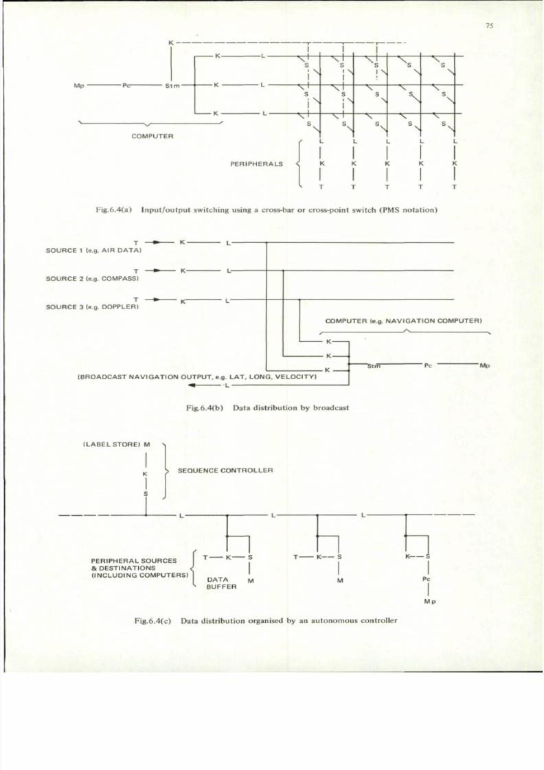
7/29/2019 Agard-Ag-183(Principles of Avionics Computer Systems)
http://slidepdf.com/reader/full/agard-ag-183principles-of-avionics-computer-systems 83/192
75
M p • P c - S t m -
C O M P U T E R
X
• X
A :
N JN IN N N
\r L
^ t
^ tN | N N
• ^ r H
• v -
^r
• v
^ T
^rs^ r
N N \ N
• v
^
s
-v
P E R I P H E R A L S < K K
*> T
Fig.6.4(a) Inp ut/o utp ut sw itching using a cross-bar or cross-point switch (PMS notatio n)
S O U R C E 1 (e.g. AIR D A T A )
S O U R C E 2 (e.g. CO MP AS S)
S O U R C E 3 (e.g. DO PP LE RI
C O M P U T E R (e.g. N A V I G A T IO N C O M P U T E R )
A
K-
• K-
K -( B R O A D C A S T N A V I G A T I O N O U T P U T , e.g . L A T , L O N G , V E L O C I T Y )
^ L
Pc-M p
Fig.6.4(b) Data distributio n by broadcast
( L A B E L S T O RE ) M S
K S S E Q U EN C E C O N T R O L L E R
P E R I P H E R A L S O U R C E S
& D E S T I N A T I O N S
( I N C L U D I N G C O M P U T E R S )
T K S
DA T Ak
B U F FD A T A M
ER
T K S
M
K S
PcIM p
Fig.6.4(c) Data distributio n organised by an auton om ous controller

7/29/2019 Agard-Ag-183(Principles of Avionics Computer Systems)
http://slidepdf.com/reader/full/agard-ag-183principles-of-avionics-computer-systems 84/192
76
A very simple method of distributing data, which has already found wide application in avionic systems, is fora particular source of data to have a dedicated highway on which it broadcasts periodically, and in a fixed format,its data output at a refresh rate high enough to provide, for all practical purposes, continuous data (see anotherchapter ). A com puter requiring particular data "listens-in" to the appropriate highway. Such an arrangement isshown in Figure 6.4(b).
A more sophisticated method is to arrange for some form of P.C.U. or autonomous controller to determine thesequence in which data from a particular source is listened to by a particular destination using a time-shared bus.
Basically the controller has a local memory in which it stores the labels for the data types required in the sequencein which they are to be called. The ne xt label is taken from me mo ry, placed on the highw ay, where it is recognizedby the appro priate source peripheral and any destination peripherals requiring it. In the next step the sourceperipheral generates the required data and the destination peripherals interested accep t it. The next step is torepeat the sequence by first taking the next label from the contro ller's local memo ry. In this arrangem ent aprocessor can be joined to the highway (see Figure 6.4(c)). A develop ment of this system is to allow peripherals toindicate when they have data ready for outpu t by raising a commo n " atte nti on " line. The controller then scansthe peripherals in turn ("polls") until the demanding peripheral is detected and then serviced.
Broadcast schemes may be used wh ere relatively low data rates and response times can be tolerated . Wherehigher performance is required it is usual for the computer to control the input/output sequence and allocatepriorities, although peripherals may be allowed to bid for service. Data messages are now not usually repe ated, sothat it is imp ortan t to check th at a message has been received corr ectly. In a system with a centralized co mp utera num ber of strategies for highway organization are possible. In Figure 6.5(a) each P.C.U. is conn ected t o the I/Ocontro ller by its own dedicated highway for the transmission of con trol signals, addresses and data. This arrangement is termed a "starred" or "radial" highway system and is a relatively simple approach as all addressing andpriority co nflicts can be resolved by hardware in the I/O con troller or software in the processor. An other com monapproach is to "bus" a single highway so that it calls in turn at each P.C.U. (is "daisy-chained") or each P.C.U. isconnected to a common highway by spurs from that highway (see Figure 6.5(b)).
This "bussing" minimizes system wiring, but presents difficulties when peripherals call for service simultaneously.A reasonable compromise is to star some control signals to resolve priority conflicts (Fig.6.5(c)).
In determining the signal format and rates for highways it is often found that most avionic peripherals can beserviced by quite moderate capacity interfaces (typically less than 500 kilobits a second in commercial systems, and1 megabit a second in military system s) but a min ority re quire significantly higher information rates. One possiblesolution is to give the P.C.U.'s controlling such devices direct access to memory via their own ports on the memory
interface. This techniqu e is called "po rted stor age " and requires special logic in the interface to resolve prioritiesbetween p orts. Ported storage is also used as a means of commu nication between processors (that is in "m ultiprocessor" systems). For example in Figure 6.5(d) the m emory highway of each processor interfaces to a commonblock of memory.
A further technique is to treat all external peripherals as part of the memory, all peripheral highways beingmultiplexed onto a memory highway (Fig.6.5(e)).
A further fundamental decision is the control timing philosophy . Two basic methods are available: strobeand hand shak e. In the first the data toge ther with a validating strob e or clock signal is transm itted from the sourceand sufficient time allowed for it to be propag ated dow n the highway and recognized at the termin ation . Strictcontro l of timing and signal overlap is requ ired. For the han dshak e case, two signals (J and K) are required . Theacceptor requests data with the J signal, the source indicates with the K signal that it has placed data on the high
way, the acceptor removes it when it has accepted the data, and finally the source removes K when it has clearedthe highway again.
This handshake is not subject to timing rules and changes can be made in the length of the highway withoutsystem timing having to be modified. How ever, more signal transitions of the highway occ ur in transferring oneword.
Very often a system justifying a sophisticated I/O system to deal with some of its peripherals will have anum ber of slowly changing digital or analog signals which justify a simpler appro ach. A suitable approach is tomultiplex such signals together and present them in the form of a sequential scan which is input on a single I/Ochannel.
Where communication with peripherals remote from the main body of the computer system is required, somespecial form of link may be justified. Norm ally such a link will be serial in form and prob ably simplex, the dataand clock signals being combined as a single signal, the clock signal being implied in the data signal messagestru ctur e. For long distance transmission the digital signal is used to mo dulate a carrier suitable for transm issionover land-lines and radio-link s. This is know n as a data-link.

7/29/2019 Agard-Ag-183(Principles of Avionics Computer Systems)
http://slidepdf.com/reader/full/agard-ag-183principles-of-avionics-computer-systems 85/192
77
M p
C O M P U T E R
A
Pc
S T A R R E D H I G H W A Y S P E R I P H E R A L S
- . y A . . A ,
I K -
- S t m -
I — K •
• K
K
• T
T
Fig.6.5(a) Starred inpu t/ou tput highway
M p
1K
' D A I S Y C H A I N E D '
r~K
L
" > i_-
f KL
^ K
T
" T
T
' S P U R R E D '
1 —L
L1 ,
fL
L1 L
K
K
K
j
T
T
Fig.6.5(b) Bussed inp ut/o utp ut highway
M p -P c L
L
L
L _
L
— • > K
L
Da t a / Co n t r o l H i g h wa y
Co n t r o l H i g h wa y
M p
M
M
M p "
Fig.6.5(c) Starred control highway/bussed data highway
P c- s
IK
K
> - K
= K
: } L O W D A T A R A T E P E R I P H E R A L S
1 H I G H
? A CCE
D A T A R A T E P E R I P H E R A L W I T H
ES S T O M E M O R Y P O R T
}Pc
S T O RE W I T H P O RT S T O B O T H P RO CE S S O RS
T
T
KIs • V
- * - K
Fig.6.5(d) Uses of 'ported storage'
M p -
L m
L m -
K
Is •
m u l t i p l e x o rL m K
m u l t i p l e x o r
• P c
- L i o
L i o -
K
K
K
K
T
T
T
T
Lm = h igh speed mem o ry h i ghway
L i o • bussed i npu t / o u tp u t h i ghway
Fig.6.5(e) Inpu t-outp ut treated as extension to mem ory

7/29/2019 Agard-Ag-183(Principles of Avionics Computer Systems)
http://slidepdf.com/reader/full/agard-ag-183principles-of-avionics-computer-systems 86/192
78
All highway and link systems involve the definition of the electrical standards and codes of practice (e.g., l ine
terminat ions) to be used to ensure adequate performance in the e lect r ical environment l ikely to be encountered.
6 .5 RE LIABILITY CONSIDE RATION S
The wider applica tion of digital comp uter s in aerospace system s is crit ically dep en den t on the achieveme nt of
high reliabili ty and the development of techniques to ensure that, when faults do occur, the effect on the system
should not be catas t rophic . Faul ts can occur external ly to the com pute r sys tem, as for example due to the fa ilureof primary p ow er supplies or the input of invalid data , or within the system , eithe r due to the incorrect function ing
of hardware components or errors in software programs.
Initially the main effort has been directed to improving hardware reliabili ty by good component and equipment
des ign, supported by the development of qual i ty assurance and re l iabi l i ty engineering techniques a imed at detect ing
and reme dying weaknesses in equip men t des ign during the deve lopm ent , m anufacturing and in-service phases of the
equ ipm ent ' s l i fe. With the impro vemen t in com pon ent technology i t i s becom ing increas ingly possible to use
funct ional redundancy of components and equipments so that , in the event of the fa i lure of a part icular e lement ,
i ts role will be carried out by other elements in a manner such as to maintain system performance (see Reference 9).
This philoso phy is already widely app lied in oth er aerospace disciplines, such as airframe design and hyd raulic
con trol system design. Such digital system s are said to be "fa ult- tole ran t", the degree of fault tolerance required
being derived from the target for the reliabili ty of the sys tem .
Typically it will be necessary to define the type of fault that will be tolerated (permanent, intermittent,
t rans ient) , the tota l numb er of faul ts , the minimu m t ime between faul ts, and what degradat ion of sys tem performance
(both short - term and long-term) is acceptable .
Software faults can arise from circumstances which have not been correctly anticipated (e.g., peak loading) or
from actual errors in program min g or from the inpu t of invalid data from extern al sources. This latter fault gives
rise to the concept of data integrity - the assurance that data, particularly that transmitted from one data area of
mem ory to anoth er or one sys tem to ano ther , i s val id. The p roblem of comprehen s ively tes t ing sys tem software is
discussed in another chapter .
Faul t - tolerance and data integri ty can be provided by a com binat ion of hardware and software techniqu es
(see References 4 , 5 and 6 ). As may be exp ecte d there is a trade-off betw een wha t is possible and what is practica l.
A modem real - t ime computer usual ly has a number of operat ing modes or levels associa ted wi th i t s operat ing
system . Th e executive level has privileged mo des of op eratio n (e.g., access to all me mo ry, interna l statu s registers,
e tc . ) and task prog rams, so as to rest r ic t the interact ion betwee n such prog rams, and hence the propag at ion of faul ts .
The operat ing sys tem is des igned to respond in a coordin ated man ner to changes in sys tem re quirem ents and s ta tus
( including sys tem mulfunct ion) which may be indicated by s ta tus words , program interrupts and data interrupts .
An out l ine s t ructu re of a typical real - time operat ing sys tem is shown in Figure 6.7, where the autho ri ty of control
increases from bot tom to top.
Ka tzan 8 identifies seven main properties of an operating system, and these all warrant the attention of the
sys tem archi tect :
Access — how the user op erat es with a system . An avionic system is usually sensor driven,
a l though i t may involve man-machine interfaces .
Ut i l izat ion — the man ner in which the sys tem is used. Avionic sys tems are normal ly pre-programmed
al though operators may cal l up a l ternat ive programs from a backing s tore i f a l ternat ive
or revis ionary m odes of working the sys tem are required. Most avionic appl icat ions do
not involve a large data-base and associa ted data m anagem ent techn iques .
Perfo rma nce — deals with qua lity of service. As the avionic system is real-time and sensor driven, the
sys tem must provide adequate response t ime and through-put .
Schedul ing — determ ines how process ing t ime is a l located to jobs . Typical ly an opera t ing sys tem will
operate on a pr iori ty bas is wi th a number of pr ior i ty queues (e .g. , corresponding to data
interrupts , object programs, and sys tem tes t programs) wi th faci l i t ies to dynamical ly
real locate priori t ies according to sys tem s ta tus .
Storage — con cern ed with the alloca tion of storage to tasks. Typ ically storage can be allocated toManagemen t tasks in blocks , the l imi t ing addresses of which are determ ined by the con ten ts of base
and limit registers. Any att em pt by a task program to com mu nic ate ou tside its allocated
area wi ll be prevented by hardware and the execut ive not i f ied by inte rrup t . By adding
addi t ional bi ts to the memory word length individual words can be protected (for example
a bit can be added which, if set, prevents the particular word from being over-written)

7/29/2019 Agard-Ag-183(Principles of Avionics Computer Systems)
http://slidepdf.com/reader/full/agard-ag-183principles-of-avionics-computer-systems 87/192
79
or checked for corruption (e.g., by the use of an odd parity bit, which is set if thenum ber of ones in the corresponding binary word is odd ). Any attempte d violation ofthe protection, or a failure of parity checks, is detected by hardware and again notifiedto the supervisor by interrupt.
Sharing — the functional capability of the system to share program data and hardware devices. Theextent to which different task programs have subroutines, common data and input/outputfacilities, must be decided and the appropriate facilities and software interfaces established.
Configuration - this is concerned with the real physical system and how it appears to the task programs.Management It is required to define how the system is organized and how the organization can be
varied by the executive. For examp le, a com puter may use the technique of virtualstorage, where each task program is written as though it has available a continuous rangeof memory addresses; although the real memory of the machine is shared between allthe computer programs, and the actual addresses allocated for a particular program neednot be consecutive. Thu s a translation is required between the virtual memory addresses,which are continu ous, and the real addresses, which are not . This dynamic addresstranslation requires special hardware facilities in the mac hine. It may be a requirementfor it to be possible to remove dynamically a failing module from a system. One exampleof this is the reallocation of memory in the event of a limited memory failure by use ofthe base and limit registers. An extension of this idea treats all inpu t/ou tpu t as memoryand defines also, by loading additional registers, the type of access that is permitted.
Memory and input/output facilities can then be reallocated under executive control",although an alternative approach is to allow the registers to be controlled by a specialvery reliable configuration control module12 .
Although the above operating system prop erties are not exhaustive enough to autom atically classify specificsystems, they do form a useful basis for comparison.
The techniques of function redundancy can be classified in to two type s:
- fault masking redun dancy ,
— standby redundancy.
The fault masking redundancy is achieved by implementing the function so that it is inherently error correcting.One such approach is Triple Module Redundancy (see Figure 6.6) where a function is performed by each of threeidentical modules working in parallel and a vote taken of the outputs, the majority signal being accepted as thetrue ou tpu t. The level of modularity used can be from, say, logic-gate level upwards. Ano ther approach is the useof redundant codes which allow errors, resulting for example from transmission, storage and arithmetic and logicaloperations, to be automatically detected and corrected.
In standby redundancy the hardware system is divided into suitable modules and when a particular module isbelieved t o be faulty it is replaced by a spare standby m odule. This technique therefore involves:
- detection of a fault,
— location of a fault down to at least the replacement module level (with detection this constitutes diagnosis),
- prevention of the propagation of the fault, the corruption of essential data and the ou tput of invalid dataor control signals likely to cause catastrophic effects,
— reconfiguration to give a working system restart from a valid state (recovery ).
The control of the above action may be by software or hardware or a combination of the two and the systemmay be self-repairing or repaired under external control.
All of these functional redundancy techniques involve the use of additional hardw are. In fault-masking logicthis is the redun dant m odules, the voting logic, or the coding and decoding logic. Standby redundan cy involvesnot only the replacement modules but also the extra equipment required to diagnose the faulty modules (e.g.,BITE) and effect the necessary switching to replace it. Extra equipm ent involves an increased p robability ofcom ponen t failure and increased equipm ent cost. Thus the design of a reliable system involves trade-offs which areextensions of the system con siderations already discussed. Again a modular level of analysis is applicable, but nowinvolves the reliability of possible modules and the corresponding additional hardware involved in the functionalredunda ncy. The reliability of the individual modules and additional hardware can be computed from the failurerates of the basic com pone nts if these are known. Often measured failure rates for the com pone nts used underthe appropriate conditions of use are not available and some acceptable set of representative figures are used as abasis of comparison. However, it must be remembered tha t, under these circumstances, the absolute failure ratespredicted for the system may not be valid.

7/29/2019 Agard-Ag-183(Principles of Avionics Computer Systems)
http://slidepdf.com/reader/full/agard-ag-183principles-of-avionics-computer-systems 88/192
80
SINGLE TM R STAGE
F U N C T I O N A L
M O D U L E SV O T I N G
L O G I C
C H A N N E L 1 A F A U L T
T Y P E A
C H A N N E L 1
V
T Y P E A
\ \ /
y ^ C H A N N E L 2 A F A U L T
C H A N N E L 2
- f r\ / \ /
7x\T Y P E A
C H A N N E L S
C H A N N E L 3 A F A U L T
N \
F U N C T I O N A L
M O D U L E SV O T I N GL O G I C
C H A N N E L 1 B F A U L T
V = two o u t o f th ree vo te r
Fig.6.6 Triple module redundancy (TMR)

7/29/2019 Agard-Ag-183(Principles of Avionics Computer Systems)
http://slidepdf.com/reader/full/agard-ag-183principles-of-avionics-computer-systems 89/192
81
M A C H I N E B O U N D A R Y
A L A R M
I NT E RRUP T S
D A T A
I NT E RRUP T S
P R O G R A M
I NT E RRUP T S
RE A L - T I M ECLOCK
H A R D W A R EI N T E R F A C E
P R I O R I T YASSESSMENT
O V E R R I D E
E X E CUT I V E
F A U L T I N D I C A T I O N
S T A T US
fM E M O R Y
C O N T R O L
C O N F I G U R A T I O NC O N T R O L
SUPERVISOR
F A UL T P RO CE DURE S
I N P U T / O U TP U T C O N T R O L
P RO G RA M S E L E CT I O N( M U L T I - A C T I V A T I O N )(PRIORITY ASSESSMENT)
CY CL I C F L A G G I NG
I NT E RL A CE D T E S TP RO G RA M S
M E M O R Y
BASE & L IM ITREGISTERS,ACCESSREGISTERS.
TIME OUTF A I L URE S .F U N C T I O N A LF A I L URE S .
TASK OR OBJECTP RO G RA M S
FLAGS FOR SERVICE
M E M O RY
BASE LOA D P ROGRAMS
( Z E RO P R I O RI T Y )(TEST PROGRAMS)
Fig.6.7 Typical general structure of an operating system

7/29/2019 Agard-Ag-183(Principles of Avionics Computer Systems)
http://slidepdf.com/reader/full/agard-ag-183principles-of-avionics-computer-systems 90/192
82
Among the advantages of the masking technique is the immediacy of the corrective action, its capability ofdealing with permanent and transient faults, and the relative ease of conversion of a non-redundant design to aredu ndan t one . The disadvantages include the need to keep all the redun dant u nits powered, the difficulty ofsynchro nizing the clocks of parallel units, and the difficulty of pre mission check ou t of perman ently w ired un its.
Systems based on standby redundancy have the advantage that all the spares can be utilized (i.e., the systemswill continue to operate at the simplex level), the number of spares at each stage can be optimized in terms of thereliability of the modules, only the on-line units need be powered, and the replacement switch provides fault
isolation betw een m odu les. Usually with each additional failure the capability of the system is reduced , althoug h itcon tinues to operate in a degraded way : the so-called process of "graceful deg rad ation ". As intercon necting highways and switches may themselves fail, usually some redundant form of interconnecting highway is required,increasing the complexity of the system design considerations discussed in a previous section.
Most published designs of fault-tolerant systems are based on standby redu ndan cy, but use error detectin g codesas an aid to fault location, and masking logic in the basic control equipment necessary for system reconfiguration.Significant improvement in mission reliability is only possible if the switching devices and monitors used for reconfiguration are much more reliable than the functional modules being switched.
A further con sideration for the system designer is the choice of memory tech nolog y. The conve ntional corememo ry is a destructively-read random access memory (R.A.M.) system. Tha t is data in mem ory is destroyed duringthe reading ope ration and must be restored from ex ternal buffer store if it is to be retained. This implies that thereis a possibility of information in store being corrupted by electrical interference during operation, although corememories are normally designed to minimize such occurrences and can, for example, be designed to shut-down in asafe sequence in the event of primary p ower supply failure. There are techniqu es for reading magnetic core andthin-film memories non-destructively, or alternatively hard-wiring the information into the store, to give read-onlymemory (R.O.M.) which can be used for essential data and program, including programs required for recovery.Similar techniques are possible with memories based on semi-conductor techniques.
It is also possible to use some form of "backing store" as the source of program and initial data in a recoveryprocess, for example to replenish a R.A.M. store which has experienced a transient fau lt. The "back ing sto re " holdsthe data in some reasonable permanent form (for example on punched plastic tape or as digitally encoded magnetictape). Typically such stores have relatively slow reading speed, which must be allowed for in designing the recoverysequence.
The above assumes that it is econ om ic to use immediate access mem ory for bo th program and data. In some
applications (e.g., of a management type) the amount of storage required may justify the use of some form of bulkstorage such as drum s, discs and m agnetic tap e, albeit tha t such devices are difficult to design for use in a hostileenvironmen t. The system architect is then involved in planning a memory hierarchy and data management system.
6.6 EXAMPLES OF AVIONIC SYSTEM ARCH ITECTURE
Other AGARD publications have given examples of the application of computers in aerospace systems(References 12, 13 and 14) and Langley19 gives a useful review of avionic data processing requirements.
A simple matrix for system classification is given in Figure 6 .8, and a num ber of typical avionic systems havebeen related to it. The matrix identifies systems as being pote ntially capable of producing catastro phic and non-catastrop hic failure mod es. How ever, usually the effect of failures of a system are complex and lead to a spectrum
of effects which can be analyzed by the Fault-Tree Analysis techniques described in another chapter.
It is difficult to think of any applicatio ns of dedicated or integrated single compu ter systems which can causecatastrophic failure, as usually the user has required some form of manual override or reversionary mode to bepossible.
Interesting examples of system architecture for space applications have been described in the literature (seeReferences 14 and 17), bu t und erstandab ly little information has been published relating to modern m ilitary aircraftand satellites.
However it is apparent that the implementation of the avionic systems of a number of new military aircrafthas been made possible by developing the system within a defined system architecture (e.g.. References 20 and 22).It is anticipated that this approach will considerably simplify the additon of new equipments or operating modesduring the life of the aircraft concerned.
A particularly interesting area of international activity is the development of long Range Patrol Aircraft havingboth a surveillance and attack role. Such aircraft typically carry a num ber of sensors, such as active and passiveradars, infra-red scanners, and optical devices (search lights and Low-Light T.V.) for detecting air and surface targets;passive and active sonobuoys and Magnetic Anomaly Detectors (M.A.D.) for detecting sub-surface targets plus an

7/29/2019 Agard-Ag-183(Principles of Avionics Computer Systems)
http://slidepdf.com/reader/full/agard-ag-183principles-of-avionics-computer-systems 91/192
A P P L I C A T I O N
Aircraft
Spacecraft/
Missile
S A F E T Y ,
MISSION
S U C C E S S ,
ESSENTIAL
No
Yes
No
Yes
DEDICATED
(SPECIAL PURPO SE
C O M P U T E R)
Inertial
Navigation
System.
Air data unit.
Engine health
Monitor.(Chapter 11)
Head-up
Display Contro l
Inertial
Reference
INTEGRATED (CENTRAL COMPUTER)
(SINGLE PROCE SSOR) (MULTI-PROCESSOR)
Navigation/Attack.
Stores management.
Automated ground/
air data exchange.
Terra in following/
avoidance.
Satellite data
handling
(Ref. 15).
Missile auto-pilot.
Missile guidance.
Spacecraft
guidance (with
manual reversion).(Ref. 13).
Sensor processing
Stability
augmentation
system.
Deep-space probe
(Ref. 17).
Launcher guidanceand control
(Ref. 13).
FEDERATED
(MULTI-COMPUTER)
Long range patrol air
craft system (includes
sensor processing)
(Ref. 21).
Airborne early warningsystem.
Area navigation.
Full authority engine
control.
Auto landing/
Auto pilot.
Space laboratory
information system,
(Ref. 14)
Fig.6.8 Classification of typical computer-based avionic systems

7/29/2019 Agard-Ag-183(Principles of Avionics Computer Systems)
http://slidepdf.com/reader/full/agard-ag-183principles-of-avionics-computer-systems 92/192
84
array of missiles, guided and conven tional bom bs and torped oes for air-to-surface attac ks. Given also that suchpatrol aircraft often operate in cooperation with other aircraft and ships and that this involves the exchange oftactical data, often automatically via data-link, it is apparent that this is an application where most aspects ofcomputer architecture are involved.
A speculative block diagram of a possible system for such a patrol aircraft is shown in Figure 6.9. An illustrationof the com plexity of a typical aircraft installation is provided by Figures 6.10 and 6 .1 1. The various sub-systems aredivided into Senso r, Tactical, Flight Contro l and Weapon areas. Several of the sensors mentioned can generate large
qua ntities of analog and digital data (e.g., radar video) at high rates. The design of the processing of such signalsinvolves trade-offs between processing methods (e.g., the use of analog, special-purpose and general-purposeprocessors) and a choice of ways of spreading the processing loads (e.g., using a central high-power processor or anum ber of lower-pow ered proce ssors). The strategy is to attem pt to con fine the high-rate signals to the sensor-processing areas and to spread the com puting load by using buffer-storage and ported-storag e techn iques. Theobjective of the sensor processing during the surveillance role is to present essential target and other data to thetactical system so that information can be correlated and compiled into a tactical picture which a human operatorcan use to make tactical decisions and initiate or control any subsequ ent attack phase. The signals transm itted toand from the tactical sub-system are relative low rate signals (e.g., target classification and position) which can behandled by bussed serial highways and serial data-link s. The assessment of the tactical situation involves threatevaluation, engageability assessment and the allocation of weapons to targets, and such decisions can be computeraided. The final attack phase involves the ch eck-o ut, initialization, firing and guidance of weapons, perhap s via a"stores management" sub-system, and possibly the control of the aircraft flight path either directly via the autopilot or indirectly by displaying "d ire cto r" signals to the air crew. In the diagram a numb er of signals between theflying contro ls and the co ntro l surface actu ator s are shown as being digital. This assumes a "fly-by -wire" philosoph ywhich has yet to gain general acceptance.
Chapter 8 surveys the total systems and computer architecture considerations involved in a specific application:the co ntro l of jet eng ines. This is an interesting ap plication inasmuch as it is proving difficult to get digitaltechniques accepted for full-authority control even though experimental digital systems have been successfullydem on strated . It is a typical case of replacing an established and proved tech niqu e (namely hyd ro-mechan ical andelectrical contro l) when aircraft safety is directly involved.
REFERENCES
1. Bell, C.et al.
Comp uter Structu res: Readings and Exam ples, McGraw-Hill Book Co., New York,1971.
2. Knight, Kenneth,E. Changes in Com puter Performance, Datam ation, V ol.12, No.9, pp. 40-54, September1956.
3. Malach, E.G. Job-Mix Modelling and System Analysis of an Aerospace Multiprocessor, IEEE Trans,on Computers, Vol. C-21, No.5, pp. 446-454, May 1972.
4. Avizienis, Algirdas Fault Tolerant Computing, an Overview, Computer, Vol.4 No.l, pp.5-8, January/February 1971.
5. Carter, W.C.Bouricius, W.G.
A Survey of Fault-Tolerant Architecture and its Evaluation, Computer, Vol.4, No.l,pp. 9-16, January/February 1971.
6. Elspas, Bernardet al.
Software Reliability, Computer, Vo l.4, N o.l , pp . 21-27, January/February 1971.
7. Cochran, W.T.et al.
What is the Fast Fourier Transform? IEE Trans, on A udio and Electroacoustics,Vol. AU-15, No .2, pp. 45-55, June 1967.
8. Karzan, Harry Operating Systems Architecture, AFIPS Conference Proceedings, Vol.36, pp. 109-117,May 1970.
9. Von Alven, William H.et al.
Reliability Engineering, Prentice-Hall Inc., New Jersey, 1964.
10. Williams, R.K.. System 25 0 - Basic Concep ts, Conference on C omp uters, Systems and Technology,IERE Conference Proceedings No.25, pp. 157-168, October 1972.
11. Crapnell, L.A. An Econom ic A rchitecture for Fault Tolerant Real Time Com puter Systems,Conference on Computers, Systems and Technology, IERE Conference Proceedings,No.25, pp. 119-130, October 1972.

7/29/2019 Agard-Ag-183(Principles of Avionics Computer Systems)
http://slidepdf.com/reader/full/agard-ag-183principles-of-avionics-computer-systems 93/192
BS
12 . Leondes , C.T.
et al.
Com puters in the Guidance and C ontrol of Aerospace Vehicles , AGA RDog raph No .15 8,
Februa ry 1972 .
13 . Miller, J.E.
et al.
Space Navigat ion Guidance and Con trol , AGAR Dograp h N o. 105, 1966.
14 . Keonjian, E.
et al.
Au tom at ion in Man ned Aerospace Sys tems, AG ARD Conference Pre-Print No .l 14,
Oc tobe r 1972 .
15 . Remmington , J .E .
et al.
An Out l ine of the Ferrant i Data Handl ing Sys tem Proposed by the Sud-Aviat ion Group
for Project L.A.S. , Conference on Aerospace Co mp uters in Rocke ts and Spacecraft ,
C.N.E.S. Paris , December 1968.
16. R a m a m o o r t h y , C . V .
et al.
Specia l Issue on Fau l t Tolerant Co mp ut ing, IEEE Tran s , on Co mp uters , Vol . C-20,
No.22 , November 1971 .
17 . Hopkins , Albert L. A Faul t Tolerant Informat ion Process ing Sys tem for Space Vehicles , IEEE Trans , on
C o m p u t e r s , V o l . C - 2 0 , N o . l l , p p . 1 3 9 4 - 1 4 0 3 , N o v e m b e r 1 9 7 1 .
18. Rols ton , Anth ony Int ro duc t ion to Program ming and Co mp uter Science, McGraw-Hil l Book Co. , New
Y o r k , 1 9 7 1 .
19 . Langley, Frank J . A Universal Fun ct ion Un i t for Avionic and Missi le Sys tem s, Proceedings of the Nat ional
Aerospace Elect ronics Conferen ce, pp. 178-185. publ ished by the IEE E, New Y ork,
1971.
20. Elson, Benjamin E. BI - A vionics are Geared to Operat ional , Growth Need s , Aviat ion Week and Space
Techn ology , pp. 52-54 , Apri l 23rd 19 73.
21 . P l a t t n e r C . M .
22 . Elson, Benjamin E.
Advanced ASW Gear, Space Economy Mark Design of S-3A, Aviat ion Week and Space
Technology , pp . 95-10 7 , Sep tember 15 th 196 9 .
AWACS Uses Flexible Computer , Aviat ion Week and Space Technology, pp. 106-109,
September 11 , 1972 .

7/29/2019 Agard-Ag-183(Principles of Avionics Computer Systems)
http://slidepdf.com/reader/full/agard-ag-183principles-of-avionics-computer-systems 94/192
E X T E RNA L E NV I RO NM E NT SENSOR SUBSYSTEMS T A CT I CA L S UB S Y S T E M S
X
O P E RA T O F T S \D I S P L A Y S * I T A C T I C A LCONTROLS I CONTR OLLER
AI R
S URF A CE
S UB -S URF A CE
F L O A T I N GA CO US T I C
SENSORS
I S O NO B UO Y S I(Passive - e g DIF AR)(Act ive - eg CASSI
OPERATOR'SDI S P L A Y S * \ WE A P O NCONTROLS I CONTRO LLER
RA DI O A I DS
(eg Beacons. OMEGA. LOR AN
DECCA. e tc . lCO O P E RA T I NG F O RCE S
K E V -
a_fe______ Ana lo gue signal path
y High data-rate digital signals
— ^ Low data-ratt digital signals
it Possible digital com puter
app l ica t ionFL IGHT CONTROL SUB SYSTEMS WEAPONS SUB SYSTEMS
Fig.6.9 Block diagram of a typical avionics system for a military long range patrol aircraft

7/29/2019 Agard-Ag-183(Principles of Avionics Computer Systems)
http://slidepdf.com/reader/full/agard-ag-183principles-of-avionics-computer-systems 95/192
87
Fig.6.10 An example of mod em avionics system installation in a patrol aircraft
Fig.6.11 View of modules of avionic equipm ent installed in bays of patrol aircraft

7/29/2019 Agard-Ag-183(Principles of Avionics Computer Systems)
http://slidepdf.com/reader/full/agard-ag-183principles-of-avionics-computer-systems 96/192
88
CHAPTER 7
DEFINING THE PROBLEM AND SPECIFYING THE REQUIREMENT
S.Boesso and R.Gamberale
7.1 INTRODUCTION
The definition of the computer characteristics is largely an iterative cut-and-try process, where sets of oftenconflicting parameters have to be chosen in order to satisfy the requirements at the minimum possible overall cost.
The primary requirements to be satisfied are functional, i.e., concern the capability of the computer to
perform the tasks assigned to it within the available time.
Other essential requirements are physical, as the computer must be able to operate properly in a certainenvironment with acceptable reliability and maintainability and its weight, volume and power consumption cannotexceed certain limits.
The present Chapter will deal only with the functional requirements and will aim at the definition of amethodology for deriving them from the knowledge of the tasks to be performed.
The considerations presented may be applied both to determine the suitability of a certain computer architectureand to compare different comp uters against a given application.
In any case, it should be kept in mind that no computer can be judged as adequate or inadequate for itself,
but only with reference to a well-defined job that it would have to handle.
Therefore it is necessary that the job, or mission, be clearly described not only quantitatively, but also in termswhich are desired of the computer and which allow the adequacy of a chosen architecture to be verified.
The treatment will start with a brief survey of typical tasks of an avionic system, from which a sample willbe picked up to be further analyzed as an exam ple. System functions will then be introd uced , to arrive atdefining what the computer is expected to do.
Finally, the computer tasks will be analyzed, also with the aid of examples, in order to show how the computerrequirements can be arrived at.
7.2 SURVEY OF TYPICAL TASKS OF AN AVIONIC SYSTEM
Avionics systems of today's aircraft are intended to perform, or to aid the crew in performing, a multitude oftasks. Some of them (e.g., stores manag emen t) are peculiar to comb at aircraft, other ones (like navigation) arecommon to the military and to the civil sides of aviation.
Typ ical tasks have been identified and will be concisely recalled h ere. The defin itions given in the foregoingtext, although not pretending to be standard, are considered to be general enough to cover variations which maybe encountered in individual real cases.
Navigation and Guidance
This is defined as the determination of:
present position of the aircraft with respect to the earth, by processing sensor data,
— course and distance from present position to selected destination points (steering information).
These parameters will normally have to be displayed to the crew, which in turn will have a means of introducingposition corrections in the comp utation, w hen the aircraft is flying over a known reference po int. This latter action

7/29/2019 Agard-Ag-183(Principles of Avionics Computer Systems)
http://slidepdf.com/reader/full/agard-ag-183principles-of-avionics-computer-systems 97/192
89
is called "pos i t ion f ixing" and cons is ts of the ident i f icat ion of reference po ints (on a map display and on th e terra in) ,
determinat ion of displacement between computed and actual pos i t ion and re la t ive correct ion of the navigat ionalc o m p u t a t i o n .
Fuel Management
This task consists of the calculation and display of:
— Fuel remaining,— Maximum range
— Enduranceat present f l ight condi t ions
- Opt im um range or opt imu m end urance wi th re la ted required f light condi t ions .
Engine Cont ro l
The avionic sys tem has to moni tor and precisely control engine performance under the actual f l ight condi t ions
encountered, i .e . ,
— Receive s ignals , f rom ai rframe and engine, that indicate present operat ing parameters ,
— Store these data and compare actual performance wi th s tored data indicat ing des i red performance under
given flight conditions,
— Drive e lect romechanical devices to modify fuel f low or engine geometry to a t ta in des i red performance.
Stores Management
The "stores" are the missiles, rockets, and bombs carried by attack aircraft either under their fuselage or wings
or in the weapons bay. For this task, the compu ter-based avionic sys tem has to carry out calcula t ion and display
for the following actions:
— Select ion of weapon s ta t ions (miss i les and/or bombs),
— Weapon fusing,
— Weapon re lease ( in proper sequence) ,
— Safety inter locks for weapons ,
— Provide informat ion and number and dis t r ibut ion of remaining s tores ,
— Indicate failure of a bomb or a missile to release.
Weapon Management (Air- to-Air Combat)
The wea pon s are in this case the aircraft guns and the air-to-air missiles carried on boa rd. Th e avionic system ,
which is a key aid for the pilot to hit the target, has to:
— Calculate range rate and rate of turn of aircraft ,
— Calculate lead angles to displace target marker,
— Indicate to the pilot that the target is at a suitable range,
— Generate release instructions for air-to-air missiles or for the guns.
Air- to-Ground Attack
This task precedes , in t ime, the s tores management , and cons is ts mainly of:
— Target Acquisition (like steering for navigation),
— Target Tracking (inclusive of aircraft steering),
— Ball is t ic calcula t ion for each type of weapon chosen and generat ion of weapon re lease informat ion.
7 .3 F R O M O P E R A T I O N A L R E Q U I R E M E N T S T O SY S TE M F U N C T I O N S
An examinat ion, wi th engineer ' s eye, of the tasks described in the preceding sect ion shows that the avionic
system has to perform a few fundamental, clearly identifiable, functions which apply, more or less, to all tasks.

7/29/2019 Agard-Ag-183(Principles of Avionics Computer Systems)
http://slidepdf.com/reader/full/agard-ag-183principles-of-avionics-computer-systems 98/192
90
First of all, the system will have to acquire information from the ou ter world o r from the crew: for exam ple, flightconditions, op erator requests, engine parameters, radar range, etc. Such data are normally supplied by suitablesensors (of pressure, speed, acceleration, temperature, etc.), converted into digital form, distributed and processedas needed . The results of the processing are utilized to pro duc e comman ds (for modifying the flight con ditions ,for firing weapons, etc.) or are displayed to the crew to help them take decisions on the mission.
A number of data, either raw or processed, are stored, to be utilized at a later time, either in flight or on thegrou nd. Finally, the key param eters of the on-board systems (air-frame, engines, avionics, weapon s) have to be
continuously monitored, in order to reveal incoming malfunctions and allow corrective actions to be taken, eitherautomatically or by the crew.
The following fundamental functions may thus be identified,
(a) Data Acq uisition
— Collection, conversion, formatting of sensor-generated data in order to allow their subsequent processing,
— Collection of commands generated by the crew.
(b) Processing
— Application of mathematical and logical algorithms on collected data, in order to extract informationand commands required for the mission.
Interpretation of new commands and execution of related actions.
(c) Data and Comm and Distribution
— Distribution of data and commands, resulting from processing, to on-board users (i.e., actuators of theguidance system, of the weapons, etc.).
(d) Data Storage
— Storage of mission parameters, introduced either on the ground before flight or in flight via atelecommunication link.
— Recording of information collected in flight.
(e) Data Display
— Display to the ope rator in different forms of data ob tained as results of processing (tabula r, alphanumeric, moving map, head up, synthetic-on-radar PPI, etc.).
(0 Communication
— Transmission and reception of information from ground or other aircraft or satellites.
(g) Housekeeping and Check-out
— Monitoring of subsystems status during operation to detect possible faults.
— Fault localization and redundancy switchover.
— Evaluation of the ability of sub-systems to perform their functions under all operational conditions,by simulation of the latter by means of proper stimuli.
The diagram of Figure 7.1 shows the relationships among the functions just described.
The preceding definitions are merely a properly grouped list of "actions" that the system is required to performto fulfill its role. As such they d o not m ention w hat "black bo xe s" will be needed on-board to implement thesystem functions prop erly. Some idea of the hardware is, however, already p resent.
To begin with , let us take data acquis ition: part of this functio n, which includes Analog-to-Digital conversionof sensor data (as described in detail in Chapter 6) is normally performed by dedicated hardware, which ouputsinformation in a form suitable for being assimilated by a digital computer.
Display and interface with operato rs is also performed mainly by dedicated h ardw are: normally a mix ofelectronic and optical devices which translate digital information into letters, symbols, etc.
The main point is thus the definition of what are the system functions that the computer has to perform,interfacing with peripherals which supply it with properly coded digital data, or which translate its output intof o r m s n s p a h l p PICPU/V***!-^

7/29/2019 Agard-Ag-183(Principles of Avionics Computer Systems)
http://slidepdf.com/reader/full/agard-ag-183principles-of-avionics-computer-systems 99/192
1—u.<ca.oonl-H '
<
I/)ccooozLU
si
sO
ooc m fo1-<cZ3 •1—
o
A
IA
^
— t
— *
DATA
ACQUISITION
STORAGE
j X J i _l
• — p
-fl
DATA &COMMAND
DISTRIBUTION
1
PROCESSING
_
'
x
DISPLAY A N DMANUAL
INTERVENTION
COMMUNICATION
occen
1- ool__ UJ
<C 1—cc Mo _ iQ i _ ll—• U J
<_ I "
<_CC 00UJ_H Q
I— __ro <c
rC R E W
Fig.7.1 Fun ction al diagram of a typical computer-ba sed avionic system

7/29/2019 Agard-Ag-183(Principles of Avionics Computer Systems)
http://slidepdf.com/reader/full/agard-ag-183principles-of-avionics-computer-systems 100/192
92
From the computer's point of view, all these system functions may be reduced to two main categories:
— Exchange of data with the "external world", i.e.. Input or Output,
— Processing, which takes place within the machine and accounts also for storage and internal data transfer.
Let us now make an example, which will be gradually developed throughout this and the following sections toshow the application of the concepts presented.
Our example task is a simplified form of navigation, where the avionic system has to inform the crew of thepresent position coordinates and computer course and distance to a destination, starting from the present position.Let us assume that the aircraft has a Doppler Radar and a magnetic compass. The op erational requirements maythus be synthesized as follows:
— Compute and Display to the crew the coordinates of the present position, by suitably processing groundvelocity vector, as supplied by the Doppler Radar and heading, as supplied by the magnetic compass.
— Compute and Display, upon request by the crew, course and distance to a preselected destination point.
The preceding requirements have to be translated into a list of system functions, part to be committed todedicated hardware and part to be handled by the on-board c omp uter(s). The avionic system will:
(1) Collect and digitize speed data from Dop pler Radar.
(2) Collect and digitize heading data from magnetic com pass.
(3) Collect operator requests, from o perato r's panel.
(4) Process collected data to obtain desired inform ation: present latitude and longitude, course and distanceto destination.
(5) Display position, course and distance information to the on-board crew.
As already said, fortunately for the computer designer, not all the preceding functions pertain to the computer.This latter will;
(1) Inpu t digitized speed and heading at predetermined time intervals.
(2) Input destination coordinates from operator panel, upon request by the crew.
(3) Process speed and heading to obtain latitude and longitude of present position.
(4) Process destination coord inates to obtain (or update) course and distance.
(5) Ou tput latitude and longitude, in digital form, to display.
(6) Ou tput cou rse and distance, in digital form, to display.
The preceding procedure is to be repeated for the other tasks, to arrive at an overall definition of thecomputer system functions.
These functions will, in turn, have to be translated into computer requirements, as described in the followingsection.
7.4 FROM SYSTEM FUNCTION TO COMPUTER REQUIREMENTS
7.4.1 Presentation of the Requiremen ts
As stated in the Introduction, the present Chapter aims at describing a methodology for specifying the mainfunctional requirements for the on-board computer, i.e.,
(a) for the Central Processing Unit (CPU)
(1) Instruction set and execution times,
(2) Instruction and data word length and form at,
(3) Addressing techniques,
(4) Sub-program linkages,
(5) Interrupt techniques,
(6) Local storage.

7/29/2019 Agard-Ag-183(Principles of Avionics Computer Systems)
http://slidepdf.com/reader/full/agard-ag-183principles-of-avionics-computer-systems 101/192
93
(b) for the Mem ory
(1) Word length,
(2) Capaci ty,
(3) Cycle t ime.
( c ) I n p u t / O u t p u t
(1) Num ber and type of channels ,
(2) Transfer time (re la ted to the types of channel) .
Other cons iderat ions concerning sel f-check and repair capabi l i ty and memory protect ion are outs ide the scope
of this Chapter .
I t has to be pointed out that the m ethod d oes not yie ld a di rect and univocal solut ion of the problem "Given
a set of tasks f ind out the r ight computer" , but i t ra ther a l lows the computer requirements to be arr ived a t af ter
a somewhat recurs ive and indirect procedure .
Once the tasks have been defined and quant ized, l imi t values are derived for a number of computer parameters .
Prel iminary computer character is t ics are then assumed and (provided no mutual incompat ibi l i t ies exis t ) , these are
check ed against the tasks. Usually more than one archite ctur e may be found w hich satisfies the functional requ ire
ments; the best in terms of cost-effectiveness will have to be chosen.
A flow-chart of this process is shown in Figure 7.2. The single steps of i t will be explained with som e detailwith the aid of examples.
7.4.2 An Examp le Set of Elem entary Operat ion s
The set of elementary operations which is an application of the reverse Polish notation (so called after the
Pol ish mathem at ic ian Lu kas iewicz) is intended to serve as an example . Othe r se ts might be chosen; the m ethod ology
wou ld only be affected in deta il , bu t i ts general l ines wo uld n ot ch ange .
The set i s not a formal ly complete language, as some operat ions comprise c lasses of ins t ruct ions , which, though
different , would require the same comput in g capaci ty. For exam ple , a ll N-place shi ft in s tmc t ions are covered by a
single operatio n (N $), irrespective of their typ e: left , right, logical, algebraic, rota te, etc.
The foregoing appl icat ion of the language in our example is assumed to be performed by han d; many s teps ,
however, may conceivably be mechanized by le t t ing a com pute r perform them .
The e lements of the language
Symbol s
Th e smallest language eleme nt is called a sym bo l. In our case, the sym bols are all the capital letter s of the
English alphabet, the decimal figures from 0 to 9, the decimal point, plus the following special ones;
+ - * : , & • ! ? % = < > " / (
O p e r a n d s
One or more cont iguous a lphanumeric symbols , wri t ten from lef t to r ight , form an operand, that i s the name
of a datum which is to be operated upon.
For examp le: ABC 4. If, however, an operand cons is ts of only num eric f igures and decimal point , i t s name
is to be interpreted as i ts value in decimal n ota tio n; negative numb ers begin with the letter N , positive n um bers
are not preceded by any sign.
The re is no limit to the nu mb er of symb ols in an opera nd , but i t is con venie nt to l imit i t to a few to save
wri t ing effort and ease mechanizat ion.
A particular operand is the "flag", which can assume only two values, 0 and 1, and is commonly used as a
prog ram switch. Flags will be indicated as FLA GJ for easy identificatio n; J is the flag reference num ber.
Opera tors
An opera tor i s indicated by one of the specia l symbols presented and explained in Table 7.1 . Opera tors are
appl ied to one, two, or three operands , as fol lows:

7/29/2019 Agard-Ag-183(Principles of Avionics Computer Systems)
http://slidepdf.com/reader/full/agard-ag-183principles-of-avionics-computer-systems 102/192
94
MEMORY
FOR DATA
3
INSTRUCTION
WORD LENGTH
AND FORMAT
i'
MEMORY
FOR PROGRAM
i
TOTAL
MEMORY
l 1
C START )
• r
FUNCTIONAL ANALYSIS(MATCHEMATIC & LOGICMODEL & DATA DESIGN)
•>
TRANSLATION O F MODEL(INTO SEQUE NCES O FELEMENTARY OPERATIONS)
jMISSION STATISTICS(RECURRENCE O F EACHOPERATION IN T H E MISSION
x •
EXECUTION TIMES A N DINSTRUCTION S E T
W
^ A C C E
4
i
\ NOPTABLES
fe
LANGUAGE (SET O FELEMENTARY
OPERATIONS)
INPUT/OUT A N DPROGRAM INTER
RUPTS
YES
COMPUTER REQUIREMENTS
Fig.7.2 Metho dology flow diagram

7/29/2019 Agard-Ag-183(Principles of Avionics Computer Systems)
http://slidepdf.com/reader/full/agard-ag-183principles-of-avionics-computer-systems 103/192
95
One-operand ope rators : , ! " $
Two-operand opera to rs : + — * : & ' =
Three-operand operators: > < ?
One operator applies always to the operands that precedes it (one, two or three, depending on the operatorclass).
Macro-operators
A macro-operator corresponds to a more or less complex function, which cannot be expressed by means ofone of the operator symbols already presented.
TABLE 7.1
Elementary Operations
Operation
y
n
+
-
*
&
M,
M"
M+
M -
M:
M&
M"
X=
N$
M%
M!M>
M<
Description
Duplicate (repeat) last operand in the sequence
Complement preceding operand, bit by bit
Add
Subtract
Multiply
Divide
And
The last six operations are performed between the lasttwo operands in the sequence (either retrieved from thememory or obtained as a result of an operation).The result is left in the sequence as an operand thatreplaces the two operated upon.
Read operand M from Memory and put it in the sequ ence.
Read operand M from Memory and complem ent it, bitby bit
Add M, read from Memory
Subtract M, read from Memory
Divide by M, read from Memory
Logical AND, bit by bit, with M, read from Memory
Logical OR, bit by bit, with M, read from MemoryThe last six operation s apply to M and to the lastoperand in the sequence; the result replaces both
operands in the sequence.For M— if there is no preceding operand, the two'scomplement of M is put into the sequence.
Store preceding operand into Memory, at location labelledX.
Shift the last operand in the sequence N places, left orright, i.e., multiply or divide by 2 N .
Call Subro utine M. This operation includes saving theProgram Counter at the beginning of the subroutine andrestoring it at the end. A particular case of a subr outinecall is a macro-operator.
Unconditionally jump to location M.A > B
Jump to location M if A < B
Examples
(4 )
(2 )
(3)
(4 )
•
(1)
(1)
(6)
(5)
(7)
(Table 7.1 continued)

7/29/2019 Agard-Ag-183(Principles of Avionics Computer Systems)
http://slidepdf.com/reader/full/agard-ag-183principles-of-avionics-computer-systems 104/192
96
TABLE 7.1 (continued)
Operat ion
M?
Input N,
O u t p u t N =
Description
A = B
where A and B are the operands preceding M in the
sequence .
If there is only one operand (viz. A) they meanrespectively
Jum p to M ifA > 0
A < 0A = 0
Input datum from channel No. N ( integer) , put i t in the
sequence and t reat i t as an o peran d.
Output to channel No. N ( integer) preceding operand inthe sequence.
Examples
(8)
A macro-operator is represented as a sequence of alphanumeric symbols, always followed by the specialsymbol %.
A macro-operator can be implemented either by software as a subroutine (which would begin at memorylocation labelled with the macro-operator's name) or by hardware as a special instruction.
In the former case, the symbol % implies therefore a "subroutine call", with related instructions which releasethe control to the routine being called and return the control to the calling process at the end of the routine itself.
In the latter case, the symbol % is a reminder that the preceding alphanumeric sym bols are not an operan d, but anoperator, and implies the instruction fetch from memory.
Choice of either solution for each macro-operator will be made considering its recurrence frequency in themission, as will be said later. Different choices will yield different mac ro-op erator ex ecution time .
A macro-operator must be always preceded by the operand(s) to which it applies.
Indices
These are operand (address) modifiers which are appended to particular operands (e.g., n t h element of a datatable) separated by an open p arenthesis. Operands followed by one or more indices are treated by o perators likesimple operands.
Indices pertaining to the same operand are separated by a slash, e.g., A(J/K. Table x.x.x summarizes someof the most frequent cases.
Elementary operations
An elementary operation is the application of an operato r to one or m ore operands. It is indicated either byan operand followed by an operator symbol (e.g., M+) or simply by an operator, which in this case refers to the
preceding operands; these latter are in turn results of other operations. Table x.x.x shows the elementary operations and gives reference to a number of examples.
Statements
A sequence of elementary operations and macro-operators which describe a sequence of actions encounteredin the system task, constitutes a statement. A statement must always begin with a new line and w ith the firstsymbol of an operand. It may extend over more lines, each line ending with an operator sy mbol, and it must endwith one of the following opera tors: = < > ? ! .
Some statements may be numbered or labelled, for the analyst's convenience. Their label or num ber will bewritten at the extrem e left of the first statem ent line, separated from it by a few blank s. For exam ple:
FORM A,B + C : Z =which means that the statement labelled FORM is
(A+B) : C = Z .

7/29/2019 Agard-Ag-183(Principles of Avionics Computer Systems)
http://slidepdf.com/reader/full/agard-ag-183principles-of-avionics-computer-systems 105/192
i> 7
TABLE 7.2
Indices
Mnemonic
A
A(I
A(I/J
A(I/J/K
Description
no index
one-entry array
two-entry array
three-entry array
Diagram of Operation
Memory
Address
AIA+ I •
AIA+I
Y
ir
Y+J •
AiA+I •
YiY+J •
Z
ir
Z+ K
Memory
Contents
-Operand
•Operand
• Y
-Operand
- Z
•Operand
It can be noted that, in the Reverse Polish notation, operands and operators generally appear in a statement in thesame sequence in which the operands would be called in a computer and the operations performed upon them.
Short examples are referenced in Table 7.1 to help the rea der in understand ing. More complex exam plesfollow separately.
Examples
(1) X = A 'o p' B where 'op ' is one of the operators
+ — * : 'and' 'or '
is translated into:
A,B 'op ' X =
which indicates the following sequence of operations:
A, Read operand A from Memory and put it in the sequence ,
B 'o p' Perform the operation 'o p' betwee n operand B, retrieved from Memory and operand A,
X= Store the result into the Memory location labelled X.
(2) X = (A+B)'op'(C—D) wh ere'op 'can be one of the operators
+ - * :
is translated into:
A,B+C,D+ 'op' X=
which indicates the following sequence of operations:
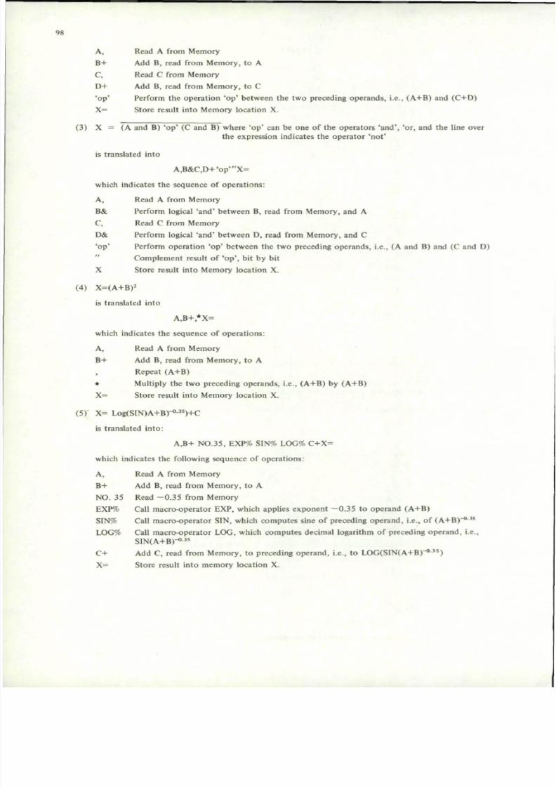
7/29/2019 Agard-Ag-183(Principles of Avionics Computer Systems)
http://slidepdf.com/reader/full/agard-ag-183principles-of-avionics-computer-systems 106/192
98
A, Read A from Memory
B+ Add B, read from Mem ory, to A
C, Read C from Memory
D+ Add B, read from Memory, to C
'op ' Perform the operation 'op' between the two preceding operands, i.e., (A+B) and (C+D)
X= Store result into Memory location X.
(3) X = (A and B) 'op' (C and B) where 'op ' can be one of the operators 'and", 'or, and the line overthe expression indicates the operator 'not'
is translated into
A,B&C,D+'op'"X=
which indicates the sequence of operations:
A, Read A from Memory
B& Perform logical 'an d' betwe en B, read from Mem ory, and A
C, Read C from Memory
D& Perform logical 'an d' between D, read from Mem ory, and C' op ' Perform operation 'op' between the two preceding operands, i.e., (A and B) and (C and D)
Complement result of 'op', bit by bit
X Store result into Memory location X.
(4) X=(A+B)2
is translated into
A,B+,*X=
which indicates the sequence of operations:
A, Read A from Memo ry
B+ Add B, read from Memory, to A
Repeat (A+B)
* Multiply the two preceding operands, i.e., (A+B ) by (A+B )
X= Store result into Memory location X.
(5) X= Log(SIN)A+B)-°-3S)+C
is translated into:
A,B+ NO.35, EXP% SIN% LOG% C+X=
which indicates the following sequence of operations:
A, Read A from MemoryB+ Add B, read from Memory, to A
NO . 35 Read - 0 .3 5 from Memory
EXP% Call macro-operator EXP, which applies expon ent —0.35 to operand (A+B )
SIN% Call macro-operator SIN, which comp utes sine of preceding operand , i.e., of (A +B ) -0 -35
LOG% Call macro-operator LOG , which comp utes decimal logarithm of preceding operand , i.e.,
SIN(A+B)-°-3S
C+ Add C, read from Mem ory, to preceding operan d, i.e., to LOG (SIN(A+B )-<)-3s)
X= Store result into memory location X.

7/29/2019 Agard-Ag-183(Principles of Avionics Computer Systems)
http://slidepdf.com/reader/full/agard-ag-183principles-of-avionics-computer-systems 107/192
99
(6) Extraction of a field (FIEL D) from a word (WRD) using a mask
(MASK)
WRD
MASK
FIELD
i N bitsand
0 0 1 - — 1 0 0
right shift, N bits
FIELDesult X=
The operation is described by the following sentence:
WRD.MASK & N$ X=
where N$ indicates the shift operation.
It is not important to specify the direction of the shift for the purpose of the analysis.
The evolution of the recurrence of the shift operation will give an indication on the required speed and,indirectly, on the shift implementation (one bit, two-bits, or multiple bits at a time).
(7) Logical IF (see FORT RAN )
IF (A.EQ.B) GO TO 3 translates into
IF (A.NE.B) TO TO 3 translates into
IF (A.GT.B) TO TO 3 translates into
IF (A.LT.B) GO TO 3 translates into
IF (A.GE.B) GO TO 3 translate into
IF (A.LE.B) GO TO 3 tranlates into
IF (A.GT.B.OR.C.LT.D) GO TO 3 translates
A,B,3 ?
A,B,CONT?3!
(where CONT indicates the following statement)
A,B,3>
A,B,3A
A,B,3>3?
A,B,3A3?
into A,B,3>C,D,3<
IF (A.GT.B.AND.C.LT.D) GO TO 3translates into A,B,X>CONT!
X C,D,3<CONTwhere X is the label of the statement corresponding tothe second condition and CONT is the label of the statement to be executed if neither condition is satisfied.
(8) Arithmetic IF (see FORTRAN )
IF (arithmetic expression) ml,m2,m3
e.g.: IF (A -B ) 1,2,3
is translated as:
A . B - K 2 ? 3 >
7.4.3 Functional Analysis
All the functions defined under the heading "Processing" in "From Operational Requirements to SystemFunctions" which are to be implemented by the computer (hardware + software), are analyzed in order to arriveat an acceptable mathematical and logical model.
This analysis will produce:
- algebraic and logical procedures on data ,
- design design: definition of variable and constant data to be operated upo n, with specifications of their
resolution and range,
- program organiza tion: sequencing and timing of programs, logical procedures for control.

7/29/2019 Agard-Ag-183(Principles of Avionics Computer Systems)
http://slidepdf.com/reader/full/agard-ag-183principles-of-avionics-computer-systems 108/192
10 0
A flow diagram describing the overall functional organization and algorithms is drawn (Fig.7.3).
Data are listed in tables like Table 7.3 and Table 7.4 including : mnem onic label, numb er of bits , and a briefbut clear description.
Let us recall the navigation example task introduced in the preceding section, and, as it implies two differentcom puting sequenc es, let us split it into two ex ample tasks which will be called Task 1 (Dead Reckon ing) andTask 2 (computation of great-circle course and distance).
Example Task 1 - Dead R eckoning (from Doppler Radar).
The flow-chart is shown in Figure 7.3 . Let us also assume that th e task is repeated o nce every 0.05 second s.
The exact formulas for the computation would be:
LAP = LAI + K f VG . COSHG dT
ISIN HG d T
COS LAP
HG = HC + VA + HDR
where
LAP, present latitude
LOP, present longitudeHG, ground trackVA, magnetic variationHDR, drift angle (from Dop pler Radar )VG, ground speed (from Doppler Radar)T, timeLAI, initial latitud eLOI, initial longitud eK, earth's curvature parameter
HC , magnetic heading (from magnetic compass)
A digital comp uter, however, cannot integrate continuou s quantities. For this reason, the integrals of theexact formulas are replaced by sums, to yield trapezoidal approximate integrations, as follows:
L A P = LA O + KT* (VGP* C O S H G P + VG O * COSHGO) & D T
L O P = LO O + KT* (VGP* SINHGP : COSLAP + VG O* SINGO : COSLAO)* D T
H G P = HC P + VA P + HD R P .
Suffixes P and O indicating present data and old data respectively, KT = K/2. The meaning of eachvariable is explained in Table 7.4.3.1; the number of bits is symbolically indicated, as actual values depend on theparticular application.
Example Task 2 — Com putation of Great Circle Course and Distance from present point P to point Dj (oneout of a few possible destin ation s). Repeated o nce per second . The flow-chart is shown in Figure 7.4.
The applicable mathematical formulas are the following:
(a) Great Circle Course formula
HCGj = ARCTA N(COSLA D i*SIN(LOD i-LOP):(COSLAP*SINLAD i-SINLAP*COSLADi*
*COS(LODj-LOP)).
(b) Great Circle Distance formula
DGCj = ARCSIN(COSHGC i*(COSLAP*SINLAD i-SINLAP*COSLAD i*COS(LOD i-LOP)) +(SINHGC i*COSLAD i*SIN(LOD i - LOP))
where:
HCGj, Great Circle Course to point Dj LOD it Longitude of DjDGCj, Great Circle Distance to poin t D-, LAP and LOP have been com puted in theLADj, Latitud e of Dj preceding Task 1.

7/29/2019 Agard-Ag-183(Principles of Avionics Computer Systems)
http://slidepdf.com/reader/full/agard-ag-183principles-of-avionics-computer-systems 109/192
101
c DEAD RECKONING 3INPUT PRESENT GR OUND
SPEED & DRIFT ANGLE
INPUT PRESENT MAGNE TICHEADING
YES
INPUT MAGNETIC VAR IATION
FROM OPERATOR PANEL
COMPUTE GROUND TRACK H G
COMPUTE A N D STORE S I N H GAND C O S H G
COMPUTE PRESENT LATITUDE
AND REPLACE O L D VALUE
COMPUTE PRESENT LONGITUDE
AND REPLACE O L D VALUE
EQUAL PREVIOUS LATITUDE
TO PREVIOUS LATITUDE
EQUAL PREVIOUS V G , H G ,SINHG, COSHG, COSLA , T O
PRESENT VALUES
YES
/RETURN A-
OUTPUT PRESENT
LATITUDE AND LONGI
TUDE
Fig.7 .3 Task I flow diagram

7/29/2019 Agard-Ag-183(Principles of Avionics Computer Systems)
http://slidepdf.com/reader/full/agard-ag-183principles-of-avionics-computer-systems 110/192
102
INPUT DESTINATION NUMBERFROM OPERATOR PANEL
YES
NO
REQUEST DATA FROM OPERATOR
INPUT LATITUDE (LADi) A N DLO NG IT UD E (LOD-j) FROM
OPERATOR PANEL
tCOMPUTE GREAT CIRCLE COURSE HCGi
FROM DESTINATION COORD. (LADi,
LOD-j) A N D FROM PRESENT POINT
COORDINATES (LAP,LOP)
COMPUTE GREAT CIRCLE DISTANCE
DGCi FROM GREAT CIRCLE COURSE,
DESTINATION COORDINATES A N DPRESENT POINT COORDINATES
OUTPUT A N D STORE H G C , AND D G C .
YES
Fig.7.4 Task 2 flow diagram

7/29/2019 Agard-Ag-183(Principles of Avionics Computer Systems)
http://slidepdf.com/reader/full/agard-ag-183principles-of-avionics-computer-systems 111/192
103
The same data are presented in Table 7.4, using the rules for indices.
7.4.4 Translation of the Model
Once the overall mission has been described as in the preceding section, it has to be "translated" into a list ofstatements making use of the elementary operations, in order to arrive at the mission statistics (i.e., type andfrequency of each elementary operation).
The translation process will be explained w ith the aid of the two example tasks already pres ented. The readerwill also have to make reference to Tables 7.1 and 7.2.
Each task is assumed to be activated by a program interrupt, which is treated like a macro-operator.
Example Task 1: Dead Reckoning
INTDEAD%
INTNAV INPUT 1, VGP =
INPUT 2, HDRP=
INPUT 3, HCP=
FLAG 1,0.OPER ?
END
where
INPUT 1INPUT 2
INPUT 3
INPUT 4
OUTPUT
OUTPUT
Call of DEAD task
Is old value of VAP
STILL VALID?INPUT 4, VAP=
OPER HCP, VAP+H DRP+H GP=
HGP,SIN%SHGP=
HGP,COS% CH GP=
VGP,CHGP* VGO, CHGO*+KT+DT+LAO+LAP=
LAP,COS% CL AP=
VGP,SHGP*CLAP : VGO,SHG)*CLAO: +KT* DT*
LOO+LOP=
LAP,LAO=
LOP,LOO=
HGP,HGO=
SHGP,SHGO=
CHGP,CHGO=
CLAP,CLAO=
FLAG2,0,END ?
LAP.OUTPUT 1 =
LOP.OUTPUT 2=
return to the calling program (included in % operator).
is the channel providing VGPis the channel providing HDRP
is the channel providing HCP
is the channel providing VAP
1 is the ou tpu t channel for LAP.
2 is the outp ut channel for LAP.

7/29/2019 Agard-Ag-183(Principles of Avionics Computer Systems)
http://slidepdf.com/reader/full/agard-ag-183principles-of-avionics-computer-systems 112/192
104
TABLE 7 .3
Task 1 Data Definition
M n e m o n i c
LAP
LAO
KT
VG P
HGP
VG O
HG O
DT
LOP
LOO
HC P
VAP
H D R P
N o. of Bi ts
n l
n l
n2
n3
n4
n3
n4
n5
nl
n l
n4
n4
n 4
Descript ion
Present la t i tude
Old la t i tude
= k /2 , where K is the earth 's curvature para meter
Present ground speed
Present ground track
Old ground speed
Old ground t rack
Time increment
Present longi tude
Old longi tude
Present magnet ic heading
Present magnetic variation
Present drift angle
TABLE 7.4
Task 2 Data Definition
Mn emo nic No. of Bi ts Descript ion
HCG (I n6 Grea t Circle Cou rse to poin t Dj
HGC(I n7 Grea t Circle distan ce to poin t Dj
LAD(I nl Lat i tude of point Dj
LOD(I nl Longi tude of point Dj
LAP nl Present la t i tude
LOP nl Present longi tudefrom Task 1
It can a lso be noted that , in wri t ing the s ta tements , we have int roduced for convenience a number of inter
med iate variables, which w ill have to be stored in to mem ory places. These variables will be listed, for each task, in
tables l ike those described in the preceding section, and taken into account when estimating the size and organization
of the data me mory (as described la ter) . For this example the intermed iate variables are shown in Table 7.5.
TABLE 7 .5
Task 1, Interm ediate Variables
M n e m o n i c
F L A G 1
SHGP
C H G P
C H G O
CLAP
C L A O
F L A G 2
No of Bits
1
m l
m l
m l
m l
m l
1
Descript ion
Flag indicating the availabili ty of a new VAP
sinHGP
cosHGP
cosHGO
cos LAP
cos LAO
Flag indicat ing that an output i s reques ted.

7/29/2019 Agard-Ag-183(Principles of Avionics Computer Systems)
http://slidepdf.com/reader/full/agard-ag-183principles-of-avionics-computer-systems 113/192
105
Example Task 2: Great Circle Course and Distance
Call of GREAT task
where
Are coordinates in memory?
Output coordinate request
INTGREAT%
GREAT INPUT 4,1=
FLAG3,1,CALL?
REQ,OUTPUT3=
INPUTS,LAD(I=
INPUT6,LOD(I=
CALL LAD(I,COS%CLAD(I=
LAD(I,SIN%SLAD(I=
LAP,SIN%SLAP=
LOD(I,LOP-COS%CLDP(I=
LOD(I,LOP-SIN%SLDP(I=
CLAD(I,SLDP(I*CLAP,SLAD(I*SLAP,CLAD(I*CLADP(I*-:ARCTAN %HG C(I=
HGC(I,COS%CLAP,SLAD(I*SLAP,CLAD(I*CLDP(I*-*
HGC(I,SIN%CLAD(I*SLDP(PV+ARCSIN%DGC(I=
DGC(I,OUTPUT4=
HDG(I,OUTPUT5=
INFLAG7.1,GREAT ? Are there other operator requests?
INPUT4 is the channel providing the destina tion number I
INPUTS is the channel providing the latitude of destina tion I, unless already in mem ory
INPUT6 is the channel providing the longitude of destination I, unless already in mem ory
OUTPUT4 is the outp ut channel for DGC(I
OUTPUTS is the ou tpu t channel for HGC(I
The intermediate variables are shown in Table 7.6.
TABLE 7.6
Task 2, Intermediate Variables
Mnemonic
FLAG3
REQ
CLDP(I
SLDP(I
CLAD(I
SLAD(I
SLAP
INFLAG7
No. of Bits
1
m3
m4
m4
m5
m5
m6
1
Description
Flag indicating that the coordinates of destinationI are in memory
Request message
cos LDP(I
sin LDP(I
cos LAD(I
sin LAD(I
when I = 1 , . . . . N(N words)
sin LAP
Flag indicating an operator request
7.4.5 Mission Statistics
Once the translation of the tasks into elementary operations has been accomplished, the recurrence frequencyof each elementary op eration can be calculated for each task and for the whole m ission. This process will be called"Mission statistics" and is conveniently performed in two steps.
In the first step the elementary operation (Table 7.7) and the macro-operations (Table 7.8) for eachtask are counted . This first count will be needed for defining program size and related m emory req uireme nts. Inthe second step, the operation distribution of each task is multiplied by its recurrence frequency in the task (Table7.9) and the same procedure is applied to the m acro-operations (Table 7.10 ). This second step defines the"mission spe ctrum ", which will be used to arrive at defining the instruc tion s et. The m achine registers have to bealso counted, i.e., those temporary storage devices for intermediate results or operands which will be needed more

7/29/2019 Agard-Ag-183(Principles of Avionics Computer Systems)
http://slidepdf.com/reader/full/agard-ag-183principles-of-avionics-computer-systems 114/192
106
TABLE 7.7
Operations Distribution
Tasks ^ y
^ ^ O pe ra tio ns
I. Dead Reckoning
2. Great Circle
3. Other Tasks
TOTAL
*
150
150
+
2
1
22 0
22 3
-
:
10
12
*
1
130
131
1
50
51
&
10
10
-
10
10
II
10
10
M,
20
17
55 0
58 7
M +
4
50 0
50 4
M-
2
80
82
M*
8
9
28 0
29 7
M:
2
150
152
M&
20
20
M -
10
10
X=
18
10
40 0
42 8
Tasks ^ y
^ y O p e r a t i o n s
1. Dead Recko ning
2. Great Circle
3. Other Tasks
TOTAL
NS
30 0
30 0
M%
1
10
50
64
Ml
1
1
100
102
M <
100
100
M >
100
100
M?
2
1
90
93
M "
10
10
1NPUTN,
4
3
50
57
OUTPUTN=
2
2
50
54
(1
27
20 0
22 7
(l /J
100
100
NOTE: Totals do not include contribution of macro-operators
Total operations = 3609
TABLE 7.9
Mission Spectrum
Tasks ^ y
^ ^ O p e r a t i o n s
I. Dead Reckoning
2. Great Circle
3. Other Tasks
TOTAL/SEC
1000
1000
+
40
1
1000
1041
2
100
102
*
1
1000
1001
1
500
50 1
&
100
10 0
.
10 0
10 0
II
100
100
M,
40 0
17
6000
6417
M+
80
6000
6080
M -
2
900
90 2
M*
160
9
3000
3169
M:
4 0
1500
1540
M&
20 0
20 0
M
100
100
x=
36 0
10
4000
4370
Tasks ^ ^
^ y Op era tio ns
1. Dead Recko ning
2. Great Circle
3. Other Tasks
TOTAL/SEC
N$
3500
3500
M%
80
10
50 0
59 0
M!
20
I
1000
1021
M<
1000
tooo
M >
1000
1000
M?
40
1
90 0
94 1
M "
100
100
1NPUTN,
80
3
50 0
58 3
OUTPUTN=
40
2
50 0
54 2
(I
27
2000
2027
(I/J REGISTERS
2
3
1000 2
1000 3
NOTE: Totals do not include contribution of macro-operators

7/29/2019 Agard-Ag-183(Principles of Avionics Computer Systems)
http://slidepdf.com/reader/full/agard-ag-183principles-of-avionics-computer-systems 115/192
107
TABLE 7 .8
Macro-Operat ions Distribut ion(not to be used in determining program size)
Tasks ^ ^ ^
m*^^ Opera t ions
1. Dead Reckoning
2 . Great Circle
3. Other Tasks
T O T A L
SIN
1
4
8
13
CO S
2
3
8
13
TA N
3
3
ARCSIN
1
5
6
ARCCOS
1
1
ARCTAN
1
5
6
O T H E R S
(20)
20
20
TABLE 7 .10
Macro-Operat ions Spectrum
Tasks ^ ^
^ ^ ^ O perations
1. Dead Reckoning
2 . Great Circle
3 . Other Tasks
TO TA L
SIN
20
4
50
74
COS
40
3
30
73
TAN
10
10
ARCSIN
1
20
21
ARCCOS
4
4
ATCTAN
1
16
17
O T H E R S
(20)
300
300
times during a s tatem ent . Every operat ion of the type ' , ' , 'M ' , ' INPU TN ,' 'M' " , encoun tered during one s tateme nt ,
read from left to right, add s one register to the num ber of those require d. All the othe r opera tions or macro -
operat ions encountered modify the number of regis ters according to the fol lowing rules:
( a) + — * : & ' d e cr em e nt t he c ou nt b y o ne ,
(b) M+ M - M* M: M" " N$ M! leave the count unal tered,
(c) X = OUTPU TN = M< M < M? reset the count to zero i f encoun tered at the end of the s tate me nt;
otherwise they leave the count unal tered,
(d) M% affect the cou nt depe nding on the num ber of their oper and s and of their results. Fo r exam ple,
t r igonometric funct ions operate with one operand which they replace with one resul t , leaving the count
unal tered.
It has to be remarked that the number of regis ters that appear to be required depends on how the s tatements
have been writte n. One can find out the state me nts which yield the maxim um cou nt and take this latter as the
num ber of registers need ed. Such num ber, in any case, can not be unreason ably hig h; if this were the case, the
contributing statement would have to be split into more parts, each part entailing a storage of an intermediate result
in to memory .
In this way, machine registers would be saved, at the expense of additional memory cycles.
Macr o-operations are listed, as said befor e, in separate T ables 7.8 and 7.10, w ith related qua ntitie s and
recurr ence frequencies, for each of them. Each mac ro is the n to be analyzed in term s of elem entar y op erati ons,
exactly as if they were tasks of their own.
The results of this analysis are shown in another section, (7.4.8).
The reason for this proc edu re will be more clear later, when the instructio n set is intr odu ced : having the
macros separated is very important to ded de w hether they have to be implemented by hardw are or by software.
The proc edure describe d before does not give a com plete spe ctrum of the mission, whe n a significant am oun t
of data is stored in me mo ry in the form of fields of wo rds. This situa tion produ ces an add itiona l wor k load in terms

7/29/2019 Agard-Ag-183(Principles of Avionics Computer Systems)
http://slidepdf.com/reader/full/agard-ag-183principles-of-avionics-computer-systems 116/192
108
of masking and shifting, which can be estimated to be proportional to the totals of the fetch and of the storageoperations performed on fields. With reference to the example 7, the following rules apply (the underlined partrepresenting the overload
(a) fetch of a field (FIE LD ) from a word (WRD)
FIELD: entails: WRD,MASK&N$
(b) fetch, with operation, of a field from a word
FIELD'op'ENTAILS: WRD,MASK&N$'op'
(c) storage of a field
RESULT,FIELD = entails: RESULT,N$WR D,MASK &WR D=
where RESULT, as its name implies, is the result of a series of preceding operations.
To render such estimate easier, it is advisable to call field operands with names which recall their nature (e.g.,appending an F to their mnem onic).
Other ad ditional workload is required for scaling shifts. The extent of this depends on the task, but in mostcases it can be estimated th at abo ut 2 0% of the arithm etic opera tions require scaling. Within such limits, fixed-p oint
arithm etic is suitable. Should th e scaling load becom e excessive, floating-point a rithm etic may be advisable.
7.4.6 Memory for Data
Data and instructions are to be stored in a certain number of memory words.
The problem is to choose the word length in order to obtain the best compromise between memory size (cost)and workload to store and retrieve data and instructions.
The following considerations are to be made.
If each data occupied a single word only a memory cycle would be required to fetch it.
Since data usually have very different lengths, this solution w ould proba bly w aste mem ory.
On the other hand, short word length would help to increase memory utilization but would require multipleaccesses to fetch long operands.
A comprom ise between these two extremes must be found: the proper word length should match the length ofmost data without excessive memory wasting. The few long data would fit in doub le words. Short data could beeither put in single words, if very few, or group ed, two o r more toge ther , as fields of word s. In the latter case, theirfetch would require overwork for masking and shifting.
The choice of the word length can be made easier by plotting a histogram of data lengths as shown in Figure7.5 for a hypothetic example, which could apply to the complex tasks already described, assuming certainvalues for word lengths.
From the figure it can be seen that if a word length, say 12 bits, were selected 600 + 800 + 5 50 = 1950 datawould occupy a single word each, while 1600 + 3200 + 1100 = 59 00 data would occupy a doub le word each. Atotal of 1950 + 590 0 x 2 = 13,750 memory words would be required.
Memory capacity in bits would be: 13,750 x 12 = 165,000 bits.
Memory occupancy would be 99,400 /165,000 = 0.6.
If a 16-bit word length were chosen, the following results would be obtained:
600 + 800 + 550 + 1600 + 3200 + (1100 x 2) = 8950 16-bits words: 8950 x 16 = 143,200 bits.
Memory occupancy: 99,400/14 3,200 = 0.69.
If the three shorter groups of data were grouped in two-field words, they would be contained in 1000 words,so the total words would be 8000. Then 800 0 x 16 = 128,000 bits.
Memory occupancy: 99 ,400 /128 ,000 = 0.78.

7/29/2019 Agard-Ag-183(Principles of Avionics Computer Systems)
http://slidepdf.com/reader/full/agard-ag-183principles-of-avionics-computer-systems 117/192
10 9
In the latter case, the time for fetching would increase. The ex tent of the increase can be evaluated as said ina previous section.
It is to be remarked that grouping should be limited to data belonging to the same table message, i.e., dataused by the same programs, in order to simplify addressing.
The procedure for organizing memory for data can be summarized as follows:
(a) The data defined during the functional analysis are subdivided in tables according to their usage by subprograms (see, for example, Tables 7.3 to 7.4).
(b) Very-short-length data belonging to the same table are joined tog ether to form comp osite data (two- orthree-field words).
(c) A histogram of data lengths is drawn (Fig.7 .5) where composite data are considered with the ir resultinglengths.
(d) The total of mem ory bits for data is evaluated by adding all the lines of the histograms, each weighted byits corresponding number of bits.
(e) A memory word length is tentatively selected and is plotted on the histogram. The length should bepreferably chosen as a multiple of four or eight to simplify hardware.
( 0 The total of memory w ords required for data is evaluated by adding all the lines of histograms includedbetween a single and a double word-length and so on.
(g) The numbe r of bits of the resulting mem ory is evaluated m ultiplying the to tal num ber of words by theselected word length.
(h) The degree of memory occupancy is evaluated as the ratio of the infonn ation bits derived in (d) and thememory bits derived in (g).
(i) The steps from (e) to (h) are repeated for a different word length in order to maximize the memoryoccupanc y. Few tentatives are required to obtain a good result.
The memory capacity obtained in step (0 is to be increased by a certain amount (say 20 + 30%) to compensate forpossible underestima tes. The value thus obtained will have to be added t o the words required for program storage,as later described.
2-
oZm
O
o
sCM
Ool O
ooCO
oo
600 x 2
800 x 5
550 x 10
1600 x 13
3200 x 14
1100 x 21
TOTAL
=
=
=
=
•
=
1200
4000
5500
20800
44800
23100
99400 BITS
g
-J I I I I I I I I I I I I I I I I 1 I L I I I I I I I I I I I L
8 16 24 32
WORD LENGTH (B IT S )
Fig.7.5 Data length statistics

7/29/2019 Agard-Ag-183(Principles of Avionics Computer Systems)
http://slidepdf.com/reader/full/agard-ag-183principles-of-avionics-computer-systems 118/192
110
In our example, if 8000 words have been estimated (in step (0) and an allowance of 20% is applied, the totalwill be 9600 words.
7.4.7 Input/Output
The term I np ut/O utpu t indicates the data exchange between the comp uter and the rest of the system. Fromthe mission statistics the following parameters have been made available:
— Number of Input Channels,— Number of Output Channels,
— Throughput for each Channel.
The organization of data acquisition and distribution is described in another chapter; the problem dealt withhere is the data exchange between the computer Input/Output (I/O) section considered as a whole and the computermemory.
Let us recall how I/O exchanges are written in terms of elementary op erations. For Inp ut from chan nel Nto memory location LOC we would write:
INPUT N, LOC=
while for Output we would write:LOC.OUTPUT N=
If either operation is performed under program control, two instructions will be required corresponding tofour memo ry cycles (t ^ , as explained in the following section).
If, otherwise, Direct Memory Access (DMA) is used, one memory cycle per word will be required.
The latter solution is to be preferred for those channels with higher throughputs, which would otherwiseconsume excessive time.
External program interrupts represent also a communication from the system to the computer, to ask for themodification of the program sequence in order to have some particular actions executed. Interrup ts do appear in
terms of elementary operations where they are treated like macro-operators; use of proper names (e.g., INT K%)may permit easy identification of interrup ts. Number of interrupt channels and related recurrence frequency isthus available from mission statistics. Generally speaking, a program interru pt system can be single level or multilevel.
In a single level interrupt system, as soon as an interrupt is accepted, further requests from peripheral devicesare automatically locked out until a reset signal is received.
The priority in executing the routines associated to different requests is stated by software under control ofan Executive program.
In a multilevel interrupt system, instead, the execution of an interrupt routine is stopped if a higher priorityrequest occu rs. This implies an auto m atic storage of the CPU configuration related to the curren t, lower priority
routine and a reloading of the proper machine registers when the routine associated with the higher priority interrupthas been com pleted . The single level system is simpler from a hardw are stand poin t, but increases the burden of theprogrammer as well as the execution times.
Multilevel interrupt organization is more powerful but makes use of more hardware and therefore it requiresmore power to operate.
This latter organization is preferable when multi-programming is employed.
The interrupt execution time, i.e., the time required to call the related interrupt routine to save the ProgramCounter and other machine registers, and to resume the preceding program at the end of the routine, restoring thecon tents of the above registers, depe nds on the solution cho sen. Many possibilities exist: a few will be presentedas examples with the estimated execution time, assuming that two machine registers (Program Counter andAccumulator) are saved.

7/29/2019 Agard-Ag-183(Principles of Avionics Computer Systems)
http://slidepdf.com/reader/full/agard-ag-183principles-of-avionics-computer-systems 119/192
I l l
(a) The interrupt channel supplies the memory address to jum p to, for starting the interrupt rou tine:
registers' saving
fetch of resume instruction
registers' restoring
2 tM
1 t M
2 t M
TOTAL TIME 5 tM
(b) The interrup t channel defines a memory loc ation whose conten ts are the address to jum p to, for startingthe interrupt routine:
registers' saving
fetch of jum p ad dress
fetch of resume instruction
registers ' restoring
TOTAL TIME
2
1
1
2
6
tM
(M
*M
lM
tM
(c) The interrupt ch annel defines a mem ory location containing the first instruction to be executed.
The instruction calls the subroutine:fetch of call instruction
registers ' saving :
fetch of resume instruction
registers ' restorin g :
T O T A L T I M E
1
2
1
2
6
»M
lM
lM
t M
t M
Method (b) and (c) are to be preferred to method (a) because they realize full program control on jumpaddress.
As far as the estimate of mission execution time is concerned , we can assume 6 t̂ j for every program inter rupt.
7.4.8 Execution Times and Instruction Set
From the description of the tasks and from the mission statistics, a tentative definition of the instruction setmay begin.
It is to be pointed out that this problem does not have a unique solution, as more instruction repertoires canbe conceived which comply with the mission requirem ents. The param eters involved are so many th at, to ourknowledge, no quantitative and object method has yet been devised.
A solution is thus found after a cut-and-try proces which relies considerably on the skill and experience of thedesigner.
The first qua ntity which is to be estimated is the mission execution tim e. To do this, a parametric duration isassigned to each elementary o peration , as a linear comb ination of memory cycle t^ and of CPU cycle tcp n • T heoperation M+ , for exam ple, is assumed to last 2t ^ (one for fetching the instruction and one for executing it); th eoperatio n N$ is assumed to last t^ + N t^pij . These assignments are based on preliminary ideas of the m achinetiming that the designer has already in his mind. A simplifying h ypothesis w hich is generally reasonable is to assumetfgpu is less than tM (for core memories and parallel CPUs this is certainly true); thus during one memory cycle,more CPU cycles can be performed.
An example of the process just presented is shown in Table 7. 11 , which applies to the exam ple missionstatistics of a previous section. It is advisable to treat macro-operators s eparately ; in our case, each macro has beendeveloped into elementary operations and a tentative execution time (in parametric form) assigned to it by addingthose of its elementary op eration s. The steps of this process are not shown; approxim ate results appear inTable 7.12.
Now, the mission execution time per second, or mission "duty", can be estimated in parametric form, byadding the frequencies F M of tM and Fppjj of tCpy which appear in the two rightmost columns of thetwo Tables 7.11 and 7.12.

7/29/2019 Agard-Ag-183(Principles of Avionics Computer Systems)
http://slidepdf.com/reader/full/agard-ag-183principles-of-avionics-computer-systems 120/192
112
The result will be an expression of the type:
D E = FM x 4M + FC P U
x lCPU < ! •
Th e value of the expression is to be significantly less than 1 (e.g., 0.5) to tak e into acco unt the appr ox ima tion of
the method and to allow for contingencies and future expansions of the tasks.
The expression contains two independent variables, but neither one is allowed to vary freely according to the
design er's fancy. Hardw are cons train ts exist , which establish up per l imits tha t it wou ld be impossible or simply to o
cos t ly to exceed.
If, using acce ptab le values of t^ and t^ pu , the abov e expressio n canno t be satisfied, the times assigned to
some elementary operat ion s or macros have to be shortened and the co mp utat ion repeated for the new values unt i l
a satisfactory Dg is fou nd.
For example , i f a macro operat ion orginal ly assumed to be implemented by software , i s implemented by
hardware ( i .e . , as a s ingle ins t ruct io n) , each mem ory cycle t^ required to fe tch a cons tant or an ins t ruct ion from
the mem ory , except the f irst one, would be replaced by one or more CPU cycles t^p y ( a s the cons tants would
be s tored in machine regis ters and the interm ediate ins t ruct ion would b e replaced b y sequences of machine s ta tes) .
The execut ion t ime would be thus cons iderably shorter , but a t the expense of a more complicated hardware.
Before we show an examp le com puta t ion, le t us int rodu ce ano ther imp ortan t parameter: the " respon se t im e"
I R , i .e., the time elapsing between the input of a set of variables and the output of the related processing results .The value of IR is very impo rtant whenever the comp uter i s part of a contro l loop. The procedure for es t imat ingI R , i .e., the time elapsing betw een the inp ut of a set of variables and the ou tp ut of the related processing re sults .
The value of IR is very impo rtant whenever the com pute r is part of a control loop. The procedu re for es t imat ing
tR for each task is l ike the one just described for the exe cutio n duty Dg , bu t applied to the operatio n distrib ution
(not spectrum ) of each task. I f n^M is the num ber of mem ory cycles and njc pj j the num ber of CPU cycles
pertaining to a task, the following expression is to be satisfied.:
lR = n T M x *M + nTCPU
x lCPU < T R
where T R is the value of the required response t ime, taking appr oxim at ion and cont ingencies into accou nt . I f the
expression is not satisfied, once again the operation execution times have to be adjusted.
Let us now int roduce an example .
Let us assume a tfgpy = 0.2 50 //sec and t^ = 1.0 /asec . Fro m the totals of Table s 7.4.8.1 and 7.5 .8.2 ,we have:
F M = 62, 090 + 66,3 68 = 128,458 sec"1
FC PU " 1 4 1 , 8 9 0 + 1 7 3 , 8 8 0 = 3 1 5 ,7 7 0 s e c - 1
w h e n c e :
which is acceptable .
D E = 128,4 58 x 1(T 6 + 315,770 x 0.25 x 10~ 6 = 0.20 7 sec/sec
Onc e the exe cut ion tim e and respon se time s have been found to be satisfactory, the further step is the definition
of an instruction set. A few choices have already been ma de, wh en assigning exe cutio n time s to each e leme ntary
ope rat ion : for exam ple , that macros can be implem ented by software , that mul t ipl icat ion and divis ion and perhap ssome macros are to be impleme nted by hardw are. Let us now return once more to the e lementary o perat ion s and
to the miss ion s ta t is t ics , and describe a number of qual i ta t ive rules to determine the ins t ruct ion set .
Some opera t ions can be di rect ly implemen ted by means of one ins t ruct ion ; for example M+ becom es: ADD
contents of a memory place (specified by instruction address) to contents of a certain machine register ( a similar
reasoning a pplies to M—, M, M* M:, etc.). If more m achin e registers are require d, i t will be desirable to specify
on which regis ter an ins t ruct ion is to oper ate : hence m ore ADD or SUB (sub tract ) or MPY (mu l t iply) , e tc . , wi ll be
specified.
Oth er opera t ions , mo re exact ly M! M > M > M? t rans la te di rect ly into unco ndi t ional (for M!) and condi t ional
j u m p s .
Oth er operat ion s , those indicated by a s imple oper ator sym bol , would corresp ond to " in terregis ter" ins t ruct ions .For exam ple: * specif ies that the two opera nds to be mul t ipl ied tog ether are contained in machine regis ters . Such
ins t ruct ions may operate on two regis ters of a random-access scra tch-pad, or on the two upper locat ions of a s tack,
or on two machine accumula tors .

7/29/2019 Agard-Ag-183(Principles of Avionics Computer Systems)
http://slidepdf.com/reader/full/agard-ag-183principles-of-avionics-computer-systems 121/192
113
Frequent encounters with indicators like (I, (I/K, etc., reveal that one or more index registers will be required.As an index register is of no use unless instructions are provided for loading, storing and testing its contents, suchinstructions will have to be provided. Use of index registers will be normally associated with actions of this ty pe :"Test contents of index register; if equal to N go to statement X , otherwise go to statement Y (i.e., continuea loop)", which would be written as
I,N,X?Y!
Such pattern of elementary operations could be implemented by means of one instruction only, of the type"Test co ntents of X , if equal to contents of mem ory location N , go to nex t instruction, otherwise skip it".
This same reasoning can be applied to other patterns of consecutive elementary operations which are recognizedto repeat themselves frequently th rough out the mission description: it would be desirable to implement such pattern sby means of dedicated in structio ns, as this would reduce mission execution d uty . For example, whenever a memorylocation M is used as a coun ter of events, we will find an expression like this:
M, 1 + M=
which can be implemented by an instruction of the type:
"increment a specified memory place by 1".
Tests on status of flags are other typical cases.
To end with, no instruction set would be complete without provisions for testing and for resetting Carry andOverflow and other machine status indicators.
Once a tentative instruction set has been defined, provided that the number of the required instructions is notin contrast with the req uirem ents, often conflicting, of the ins truction format (see the following sectio n), a finaladjustment has to be mad e. Once more , no standard m ethod exists; trial programm ing of some tasks or of the wholemission, aided, if the case, by simulation (see the following chapter) is perhaps the way most commonly followedto verify that the proposed set fulfills the mission requirements.
TABLE 7.11
Execution Times of Operations
Operations
)
+
—
*
&-
a
M ,
M +
M -
M *
M:
M &
M"
X=N$
M %
M !
Spectrum
1000
1041
102
1001
501
100
100
100
6417
6080
902
3169
1540
200
100
4370
3500
590
1021
Single Time(1 )
TM
TC P U
1 1
1 1
1 1
1 20(2)
1 36(2)
1 1
1 1
1 1
2
2
2
2 20(2)
2 36(2)
2
2
2
1 8(3)
4(4)
1 1
Frequencies
F M
1000
1041
102
1001
501
100
100
100
12834
12160
1804
6338
3080
400
200
8740
3500
2360
1021
FC P U
1000
1041
102
20020
18036
100
100
100
-
-
-
6338
55440
-
-
-28000
-
1021
(Continued)

7/29/2019 Agard-Ag-183(Principles of Avionics Computer Systems)
http://slidepdf.com/reader/full/agard-ag-183principles-of-avionics-computer-systems 122/192
114
TABLE 7.11 (continued)
Opera t ions
M
M
M?
M "
INPUTN,
O U T P U T N =
d
d / J
Spec t rum
1000
1000
9 4 1
10 0
5 8 3
5 42
2 0 2 7
1000
Single Time
( I )
TM TCPU
1 2
1 2
1 2
1 1
1 1
2
1
1 2
T O T A L S
Frequenc ies
FM FCPU
1000 2000
1000 2000
941 1882
100 100
583 583
1084
2 0 2 7
1000 2000
6 2 0 9 0 1 4 1 8 9 0
NOT ES: to Table 7.11.
(1) Includes the fetch of the instruction
(2) In case of 16-bit wo rds
(3) Average value in case of 16-bit words
(4) Includes the saving and resuming of program co un ter
TABLE 7.12
Execution Times of Macros
Macro
SIN
CO S
TA N
ARCSIN
A R C C O S
A R C T A N
O T H E R S ( 2 )
F r e q u e n c y
7 4
7 3
20
21
4
17
3 0 0
Single Time
T M TCPU
32 120
32 120
32 120
32 120
32 120
32 120
300 500
T O T A L
Partial Time
FM
2 3 6 8
2 3 3 6
3 2 0
67 2
128
5 44
6 0 0 0 0
6 6 3 6 8
FCP U
8 8 8 0
8 7 6 0
1200
2 5 2 0
4 8 0
2 0 4 0
150000
173880
NOTES:
(1) Trigon om etric functions are evaluated as 6-term series expa nsion ,x with 16 bits.
(2) The execu tion time is considered as an average value.
7.4.9 Instruction Word Length and Form at
Instructions can be classified into two main classes:
(a) memory reference instructions, concernting operations on operand(s) contained in Memory besides in the
machine registers;
(b) non-memory reference instructions, concerning operations on data in the machine registers.
The instruc tion format for class (a) will consist of two basic par ts: one defining the ope ration and the o therthe opera nd( s). The latter part could be subdivided into more sub-fields defining the proced ure to find each operand

7/29/2019 Agard-Ag-183(Principles of Avionics Computer Systems)
http://slidepdf.com/reader/full/agard-ag-183principles-of-avionics-computer-systems 123/192
115
involved in the instruction and the location w here to store the resu lt. In the simplest case (see Figure 7.6) oneoperand is always stored in a machine register called accu mula tor, while the other is in me mory. In this case, nospecial code to specify the accumu lator is required: it is understood from the operation code . The operand part(AF) of the instruction is then completely devoted to indicate the second operand in memory.
INSTRUCTION WORD
OPERATION PART OPERAND PART
OP I X AF
OP
I
XAF
OPERATION CODE
INDICATES INDIRECT ADDRESSING WHEN IT IS 1
INDICATES INDEXED ADDRESSING WHEN I T I S 1OPERAND ADDRESS FIELD
Fig.7.6 Example of single-address memory-reference instruction
In more complex formats, the operand part of the instruction defines two or three memory locations wherethe operands are to be retrieved and the result is to be stored. In this case, the full addresses of the operand s andof the result cannot be explicitly contained in the instru ction : a too long word for the instruction w ould berequired.
Usual solutions to solve this problem are "indire ct add ressing" and "ind exin g". In the former solution, the
instruction gives a reference to a location, either in the CPU or in a reserved part of the memory, where the fulladdress of the operand is stored; in the latter solution, the instruction contains a partial address which is to bemodified by the contents of an index register to obtain the full operand address.
These two types of addressing are used also for operational purposes, to access for instance a location in aone-entry array or in a two-entry array, as will be said later.
The problem of limiting the instruction word length is also presented in the simplest case of a single-addressinstruction, mentioned before.
A solution often adopted consists of an organization of mem ory into pages. A page is a block of 2 n contiguousmemory lo cations, small enough, with respect to the overall memory capa city, to be directly addressed by the nbits of the address field (AF) contained in the operand part of the instruction. An "addressing m ode " code, also
contained in the operand part of the instruction, indicates the way to derive the location of the page inside thefull memory addressing range.
Many different addressing modes have been devised. The most frequent ones are summarized in Figure 7.7,where the procedure to evaluate the operand effective address (EA , through EA5 , for the cases considered) isshown.
The classification has been made on the basis of the page location, which can be either relative (to the programcounter (PC) or to a point (POINTER)) or fixed (e.g., page "zero"), and of the page boundaries, which can beeither variable or fixed.
Variable boundaries are obtained when AF is added to the reference address, given either by the programcounter (case 1) or by the p ointer register (case 2). In case 1 the page is called " mo bile " since it "mo ves " following
the program counter during program execution.
Fixed boundaries are obtained when the least significant bits of the address are directly derived from AF whilethe most significant bits (MSB) are derived either from PC (case 3) or the POINTER (case 4) or are set to a fixednumber K (case 5).
To choose the page size the following considerations are to be made.

7/29/2019 Agard-Ag-183(Principles of Avionics Computer Systems)
http://slidepdf.com/reader/full/agard-ag-183principles-of-avionics-computer-systems 124/192
116
ooUJ1—1
c c<Cc__z__3oC O
Variable
Fixed
PAGE LOCATION
RELATIVE TO PC
(CURRENT PAG E)
(1)
EAl = PC + AF
(mobile pa ge)
(3)
EAS = MSB.PCfAF
RELATIVE TO A POINTER
(ANY PAG E)
(2)
EA2 = POINTER + AF
(4)
EA4 == MSB.POIN TERfAF
FIXED
(e.g., PAGE "ZERO")
not applicable
(5)
EAS = K + AF
(K=0 for page "zero ")
LEGEND:
EA operand effective address
PC program counter
AF add ress field
MSB. most significant bits of
• junction
POIN TER pointing register
K fixed number (K=0 for page "zero")
Fig.7.7 Addressing modes
Data are usually organized in tables. A table is a set of data which have either the same source (inpu t ch annel)
or the same destination (o utpu t chann el) or the same utilization, i.e., they are used by the same sub-program. Tospeed up the operand fetch any data inside a table should be addressed easily, once the table has been defined.
For this reason, the page size should be enough to contain the longest table. If this is not prac tical becausemost of the tables can be accommodated in a reasonable page size while a few are longer, these latter could besubdivided into subtables of suitable sizes.
The memory page should be chosen taking also into account the requ irements for program sequencing: loops,for instance, should not be longer than a page to allow jump with direct addressing.
The req uirem ents for a certain page size are often in conflict with those of the opera tion co de. From theprogrammer's point of view, having large pages means little use of indirect addressing, and therefore simplerprograms which are also shorter to execute (instructions with indirect addressing require one more memory cycle
than their counterparts with direct addressing).
Large pages require long address fields, thus leaving few bits for the operation code and reducing the numberof available operation codes for memory-reference instructions.
Thus the designer is faced once more with the problem of finding an acceptable compromise between page sizeand operation codes, in order to optimize execution and response times.
Non-memory-reference instructions, on the other hand, should not present coding problems as they wouldtypically be specified by a dedicated OP code, leaving the other many bits of the instruction word free for theinstruction code.
Input/Output instructions are often in a form similar to that of memory-reference instructions, but with AF
specifying the number of the input or output channel.
In any case, it is desirable that the information required to define instructions be packed into a word havingthe same length as the data w ord, or in some cases a mu ltiple of it. A mutual adjustmen t can be sometimesnecessary to achieve a suitable compromise.

7/29/2019 Agard-Ag-183(Principles of Avionics Computer Systems)
http://slidepdf.com/reader/full/agard-ag-183principles-of-avionics-computer-systems 125/192
117
Indirect address ing and indexing are used a lso to reference subscripted locat ion s . Tw o examp les are con s idered:
one-entry and two-entry array s . More sophis t icated cases can be encou ntered in actual prog ramm ing.
One-entry array
Let N locat ions be organized into a table beginning at locat ion TA B. Let a lso J be a num ber, ranging
between 0 to N — 1 , used to reference the said loc ation s inside the table . Th e effective ad dress of a generic
location is given by : EA = TAB + J , where TA B is derived from A F in one of the way s said before (acco rding
to the typ e of page cho sen) (see Figure 7.4.9.1 ) and J is supplied by an index register.
In case of loops J can be used to contro l the num ber of i teration and , at the same tim e, to reference da ta
inside the table on which the program applies.
Two-entry array
Let us consider a table of N x M mem ory loca tions organized as an array with N rows of M locatio ns
each. Let also J , ranging betwe en 0 to N — 1 , be a nu mb er defining a generic row of the table, and K be
ano ther num ber, ranging betw een 0 to M — 1 , defining a generic locat ion in the J1*1 row.
The overall table can be cons idered as comp osed of N subtables , wi th M elements each, beginning a t locat ions
TAB J (J = 0, . . . , N — 1 ) . Th e addresses TAB J can be contained in a reference ta ble, beginn ing at locatio n
TAB and having N elem ents , addressed by J wi th reference to TAB .
Th e effective add ress of a generic location is given by : EA = TAB J + K , wh ere TAB J is given by :
TABJ = (TAB + J) ; TAB is derived from AF as said before for the type of page used (Fig .7.6) . Th e
parentheses indicate the conte nts of mem ory locat ion specif ied. J , K are given by two index regis ters .
Using the nota tion de scribed in a previou s sectio n, an ope rand in a one -ent ry array is defined as TA B( J; an
ope rand in a two -entry array is defined as TA B(J/K (see exam ple in Table 7.2 ).
7.4.10 Memory for Program
The number of memory locat ions required to s tore the program ins t ruct ions can be evaluated according to the
following steps:
(a) From Table 7.7 the tota l numb er of e leme ntary o perat ion s in the mission is evaluated by adding al lt he numbers in the bo t tom row.
In our example this tota l number is 3609 words .
(b) The macros are expan ded in terms of e lemen tary ope rat ions .
(c) For each mac ro, the num ber of e lementary o perat io ns involved is evaluated. In our example a numb er
of 20 e lementary operat ions has been assumed to be required for each of the macros SIN, COS, TAR,
ARCSIN, ARCOS, ARCTAN, and an average value of 100 operat ions for each of the OTHER 20 macros .
The operat ions required by the macros are :
6 x 20 + 20 x 100 = 21 20 op.s
(d) Considering, as a f irst appro xim at ion, a me mo ry locat ion for each operat io n (as if a s ingle word ins t ruct ion
corresponded to each e lementary o pera t ion) , the numb er of mem ory locat ion s for program is obta ined by
adding the num ber of operat ions obtained in (a) to those in (c) . In our exa mp le:
3609 + 2120 = 5729 loca t ions .
(e) An allowance is to be left for the following reaso ns:
— double-length ins t ruct ions ( including indirect address ing) ,
— cons tan t s ,
— cont ingencies .
A tota l of 50% can be es t imated and added, yie lding:
5729 x 1.5 = 86 00 locat ions .
7 .4 .11 Tota l Memory Requ i rement s
The tota l requirements for the memory are derived by adding memory words for data and memory words for

7/29/2019 Agard-Ag-183(Principles of Avionics Computer Systems)
http://slidepdf.com/reader/full/agard-ag-183principles-of-avionics-computer-systems 126/192
118
programs. The numb er thus obtained w ill represent the memory w ords required for the mission. In our example:
Memory for data : 9600 words
Memory for programs: 8600 words
TOTAL MEMORY : 18200 words
The figure obtained must be rounded up to take into account the following considerations.
Memories generally consist of a number of identical modules, i.e. blocks of words to which contiguousaddresses are assigned. Each mod ule is a well-defined physical entity having a numbe r of dedicated electron ic circuitsand sharing oth er circuits with the othe r mod ules. Hardw are constrain ts define practical modu le sizes, which arenormally m ultiples of 1024 (!K) wo rds. Typical sizes are 4K and 8K .
As the total memory will have to consist of a number of modules, the memory required by the mission shallbe approximated by the nearest multiple of module size which exceeds the theoretical figure. In our example,assuming 4K modules, total memory size will be 20K words.
This last figure is the estimated memory requirement for the actual mission.
As already said, future exp ansions should b e foreseen. Addition and utilization of other memory modules ispossible only if the full memory address has a range wide enough (the full memory address is normally not longer
than a memory word).
If the full mem ory address is b bits, the full addressing range is 2 b memory words. In our example, where20K words are assumed to be presently required, an expansion possibility up to 32K, i.e., 60% of present memory,seems appro priate. Hence the full memory address should be 15 bits long, as 32K = 2 " .
Should this be considered not enough, a maximum memory of 65K would have to be chosen, correspondingto a full address of 16 bits.

7/29/2019 Agard-Ag-183(Principles of Avionics Computer Systems)
http://slidepdf.com/reader/full/agard-ag-183principles-of-avionics-computer-systems 127/192
119
CHAPTER 8
MONITORING AND CONTROL OF AEROSPACE VEHICLE PROPULSION
E.S.Ecdes
8.1 GENERAL INTRODUCTION
This chapter discusses the application of digital computer systems to a specific problem and cross-refers topreceeding chapters. It illustrates the practical significance of individual sections and brings particular aspects intosharper focus. The discussion is concerned with a single problem — the design of systems for monitoring andcontrol of the propulsion of aerospace vehicles.
The general contex t is related to comm ercial operation of vehicles using airbreathing engines. This limitationpermits concentration of attention on the systems problem and removes the need for any extensive discussion ofpowe rplant characteristics. Detailed treatm ents of powerplants and their operating or contro l characteristics areavailable in the literature (e.g., Reference 1).
The restriction is not serious in terms of broad po werplant characteristics. The basic features of contro lrequireme nts are common to all plants using chemical energy sources and com bustion for energy conversion. Thereare strong conceptual similarities, for instance, between throttleable rocket motors and augmented (reheated) gasturbine p owerplants. Time con stants and thrust levels differ bu t the basic problems of mixture contro l via independen t fuel and oxidant flow c ontrol and their pumping (in the general sense) remain the same. The plant c ontroldetails will be less relevant to systems using hypergolic fuels and nuclear or electric propulsion.
In the same way, the operation al criteria will be similar for vehicles which , in themselves, are as different asthe space shuttle and STOL feeder liner systems. Comm ercial and m ilitary ope rational criteria also have manyanalogous, if not entirely h omolog ous, features. Similar design trade-offs are involved for both types of organizational structure and mission objectives.
It is hoped that, within these limitations, the discussion will identify the basic principles involved and enableread-across to other types of operation and to other avionics systems disciplines.
8.2 STATEMENT OF THE PROBLEM
The problem was given the introduction as the "design of systems for monitoring and control of thepropulsion of aerospace vehicles".
The solution of the problem takes place in stages (of time), through various levels of "system" hierarchy and isbounded by many interfaces between organizations. There are two major phases in the life of a system. One leadsup to entry into service and includes the R and D steps, design validation and certification. The second stageembraces the service life and operation of the system. The objectives of these two stages differ and can produc econflicting requirements on the overall system which need careful resolution.
The levels of the system hierarchy and their relationship with the general field of technological developmentare illustrated in Figure 8.1 . At the highest level, technology and the sodal-econ omic system in teract to providean operating environment. The environment is defined primarily by legislation and controlled by regulatory b odies.This "environment" is expressed in terms of permitted noise levels, minimum safety criteria, communicationspectra, traffic scheduling limitations and so on.
At the next level, operators recognize new market opportunities or competitive threats from which they
generate strategies leading to identification of market requirements and possibly the need for legislative modificationof the operating environmen t. The m arket requireme nts in turn lead to definition of the primary mission to beaccomplished, the facilities required to complete the mission and the support arrangements required to sustain thetotal activity.

7/29/2019 Agard-Ag-183(Principles of Avionics Computer Systems)
http://slidepdf.com/reader/full/agard-ag-183principles-of-avionics-computer-systems 128/192
120
T e c h n o l o g y « -S oc i a 1 - E c o n o m i c
S y s te m
T
Operating En vironment
(Legislation, Stat utory Bodies)
ISupport
Definition
I
cI
Airframe 3
Flight
Dynamics
Market
Requirement
Mission
Definition
1Ve hicle Specification
i( Propulsion )
Powerplant
*
Controls
iFacilities
Definition
•
c1
Systems D
CommunicationsNavigationDisplays
Fig.S. 1 Overall system hierarchy
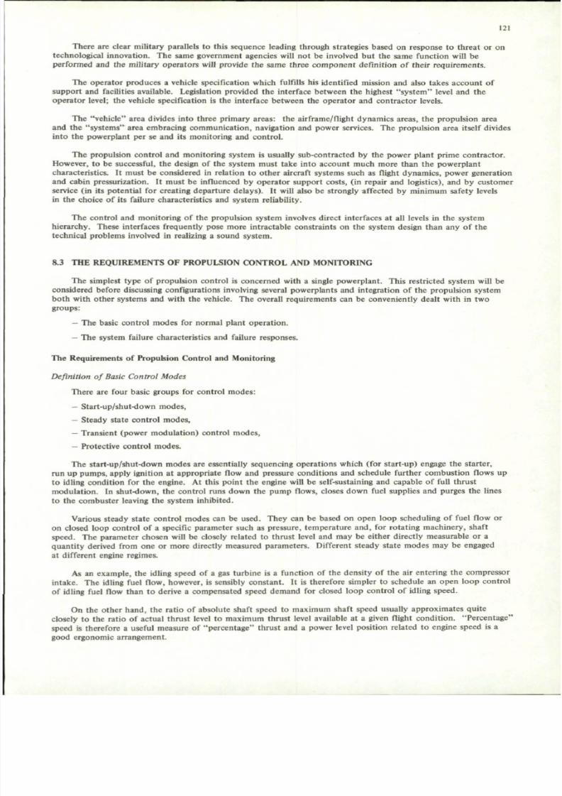
7/29/2019 Agard-Ag-183(Principles of Avionics Computer Systems)
http://slidepdf.com/reader/full/agard-ag-183principles-of-avionics-computer-systems 129/192
121
There are clear military parallels to this sequence leading through strategies based on response to threat or ontechnological innovation . The same government agencies will not be involved bu t the same function will beperformed and the military operators will provide the same three component definition of their requirements.
The operator produces a vehicle specification which fulfills his identified mission and also takes account ofsupport and facilities available. Legislation provided th e interface be tween the highest "sys tem " level and theoperator level; the vehicle specification is the interface between the operator and contractor levels.
The "vehic le" area divides into three primary areas: the airframe/flight dynam ics areas, the propulsion areaand the "sy ste ms " area embracing comm unication, navigation and power services. The propulsion area itself dividesinto the powerplant per se and its monitoring and control.
The propulsion control and monitoring system is usually sub-contracted by the power plant prime contractor.However, to be successful, the design of the system must take into account much more than the powerplantcharacteristics. It must be considered in relation to other aircraft systems such as flight dynam ics, power generationand cabin pressurization. It must be influenced b y operato r supp ort costs, (in repair and logistics), and by custom erservice (in its potential for creating departure d elays). It will also be strongly affected by m inimum safety levelsin the choice of its failure characteristics and system reliability.
The control and monitoring of the propulsion system involves direct interfaces at all levels in the systemhierarchy. These interfaces frequently pose more intractable con straints on the system design than any of the
technical problems involved in realizing a sound system.
8.3 THE REQUIREMENTS OF PROPULSION CONTR OL AND MONITORING
The simplest type of propulsion control is concerned w ith a single pow erplant. This restricted system w ill beconsidered before discussing configurations involving several powerplants and integration of the propulsion systemboth w ith other systems and with the vehicle. The overall requiremen ts can be conveniently dealt with in twogroups:
- The basic control mo des for normal plant ope ration .
- The system failure charac teristics and failure responses.
The Requirements of Propulsion Control and Monitoring
Definition of Basic Control Modes
There are four basic groups for control modes:
- Start-up/shut-down modes,
— Steady state control modes,
— Transient (power modulation) control modes,
— Protective control modes.
The start-up/shut-down modes are essentially sequencing operations which (for start-up) engage the starter,mn up pumps, apply ignition at appropriate flow and pressure conditions and schedule further combustion flows upto idling condition for th e engine. At this point th e engine will be self-sustaining and capable of full th rustmod ulation. In shut-down , the contro l runs down the pum p flows, closes down fuel supplies and purges the linesto the combuster leaving the system inhibited.
Various steady state contro l modes can be used. They can be based on open loop scheduling of fuel flow oron closed loop control of a specific parameter such as pressure, temperature and, for rotating machinery, shaftspeed. The param eter chosen will be closely related to thrus t level and may be either directly measurable or aqua ntity derived from one or more directly measured param eters. Different steady state modes may be engagedat different engine regimes.
As an example, the idling speed of a gas turbine is a function of the density of the air entering the compressorintake . The idling fuel flow, however, is sensibly co nsta nt. It is therefore simpler to schedule an open loo p contro lof idling fuel flow than to derive a compensated speed demand for closed loop control of idling speed.
On the other hand, the ratio of absolute shaft speed to maximum shaft speed usually approximates quiteclosely to the ratio of actual thrust level to maximum thrust level available at a given flight c onditio n. "Pe rcen tage "speed is therefore a useful measure of "perc enta ge" thrust and a power level position related to engine speed is agood ergonomic arrangement.

7/29/2019 Agard-Ag-183(Principles of Avionics Computer Systems)
http://slidepdf.com/reader/full/agard-ag-183principles-of-avionics-computer-systems 130/192
122
An arrangement which has been used is to combine the two modes using logical switching as in Figure 8.2.The logic is organized to select the control mode resulting in the higher engine speed and the speed control loopdemand is shaped to ensure that the fuel flow schedule will always be chosen at idle.
100% -
SPEED
SCHEDULE
DECREASING
AIR DENSITY,
FLOW
SCHEDULE
POWER LEVER SETTING
Fig.8.2 Steady-state control modes
The logic operates on the algebraic value of the co ntrol error in the two modes. Mode switching occurssmoothly because it takes place when the tw o errors are equal in mag nitude. The logic is not restricted to tw oinputs alone but can be used for several modes which need to be confined to the same group.
The transien t modes of contro l ope rate when rapid, large-scale thrust changes are called for. They p reventcombu stion m ixture limits being exceeded during transient flow changes and the resulting flame extinction . They
also prevent instability occurring either in the com bustion or in the pum ping systems. In this context, compressorinstability in a gas-turbine is the same as pum p instability in a rocket mo tor. The trans ient limits of control canbe represented on a diagram such as Figure 8.3 in which compressor (pump) pressure ratio is plotted againstcompressor mass flow. The compressor instability and com bustor extinction bound aries are shown together w ith asteady state operating line and constant (non-dimensional) speed lines.
Increase of thrust results in a pressure ratio higher than for steady running while reduction of thrust movesthe operating point towards weak extinction. The function of the transient control m odes is to ensure that thelocus of the instantaneous operating point lies within the two boundaries during thrust changes.
The protective modes of control prevent damage to the engine which could be caused by exceeding structuraldesign limits for temp era ture , pressure or rotation al speed. These design limits are absolu te values. A uniqu emaximum speed boundary cannot be drawn on a "non-dimensional" diagram such as Figure 8.3 since non-dimensional
speed is a function of inlet temp erature. The same applies to limiting temperatures in comb ustor or turbine bladematerials. These limits will norm ally be invoked during a full scale acceleration with a locus such as is shown inFigure 8.4.
It is norm al for five different mod es to be selected d uring a large scale acceleration w ithin th e space of a fewsecond s. Mode selection m ust therefore be autom atic and ther e will always be several mo des available for eachcontrolled output variable.

7/29/2019 Agard-Ag-183(Principles of Avionics Computer Systems)
http://slidepdf.com/reader/full/agard-ag-183principles-of-avionics-computer-systems 131/192
123
PRESSRATIO
THRUST
INCREASING
INSTABILITY
BO
EXTINCTION
BOUNDARY
y
MASS FLOW
Fig.S.3 Transient control limits
Selection of Basic Type of Control
The time between mode changes can be comparable with the engine time constant itself. It follows, therefore,that real-time digital computer control has a short, environment-determined response time and must use dedicated,continuously running programs for each mode of con trol. The typ e of logical mode selection described also requiresthat the mode switching be effected by "polling" rather than by interrupt-type procedures.
The basic program sequence for control is then:Read demand
Read present parameter states
Compute compensated control error values for each mode for each control output
Poll error values for each group of modes associated with each control output
Select one error from each group for each control output
Scale and output the selected errors.
(The inter-parameter cross-feeds and manipulation involved in multi-variable controllers has been omitted forsimplicity.)
So far, we have ignored any response-time criteria. Most of the time co nstan ts in the propulsion contro l systemare similar or can be handled by simple forms of m ulti-rate sampling. All the p rotective loops considered have beenconcerned with pro tection against potential failure. There are some protective loops which require very rapidresponse to external disturbances, or to actual failures in order to prevent catastrophic secondary damage.

7/29/2019 Agard-Ag-183(Principles of Avionics Computer Systems)
http://slidepdf.com/reader/full/agard-ag-183principles-of-avionics-computer-systems 132/192
124
PRESSRATIO
FLOW
SCHEDULE
OVER-TEMP
OVER-SPEED
LIMITER
LIMITER
'TRANSIENT*
CONTROL
MASS FLOW
Fig.S.4 Mode sequence during acceleration
There is now a choice in the stru cture of the system wh ich requires a careful trade-off to be m ade. Is it moresatisfactory to complicate the digital processing by introducing a priority interrupt stmcture and recovery proceduresto respond to these conditions, or is it better to provide for them by independent-sub-systems which over-ride theprimary control demands on the output actuators?
There is no blanket solution to this question . There can be a real requirement for fitting indepen dent actuators,if not com plete sub-systems. The question w as generated by considering abnormal op eration or response to failure,
particularly wh ere rapid action was required . We are therefore introdu cing into the systems-choices othe r criteriathan control of the plant under normal operating conditions.
Even the m ost basic con trol requ irem ents, such as a loop sampling rate, can be affected by c onside rationswhich have nothing to do w ith control theory but a great deal to do w ith the system as a whole. The design ofthe system must encompass all the possible operating conditions of the plant and controller including all theirpossible failure modes.
Various failure responses can be required of the system . The simplest is to force a hard-over failure to a fixedlimit. The result may be an uncontrolled thrust excursion in either direction but the magnitude of the excursionmust not prejudice the integrity of the vehicle as a whole.
This type of arrangement can sometimes be obtained by putting fixed limit stops on actuator movements,
is a meth od which m ust be used with care , howev er. It is app rop riate to limit fuel-reducing ex cursions by an"idle-flow " stop . The me thod cann ot be so easily used to restrict fuel-increasing excu rsions.
I t
An engine can only be accelerated by supplying it with more energy than is necessary for steady-state running.Acceleration the refore dep end s upo n over-fuelling. Good accelerations usually require a maximum fuel flow well inexcess of that needed for steady state operation at the structural limits for the engine.

7/29/2019 Agard-Ag-183(Principles of Avionics Computer Systems)
http://slidepdf.com/reader/full/agard-ag-183principles-of-avionics-computer-systems 133/192
125
A simple stop cannot therefore be used to limit an "upw ard s" hard-over excursion. Any stop would have tobe modulated if a failure was known to have occurred. This defeats the whole object of a protec ted hard-overfailure arrangement which is to make failure detection unnecessary.
Where failure detection is provided, then it is as easy to arrange for soft failures to occur as to arrange for limitstop mo dulation. A soft failure forces the system to a defined cond ition. In a flight con trol system this conditionis with the con trol surfaces in a neutral pos ition. In a pow erplant, the same basic "no dis turba nce " response isachieved by failing with the engine condition unchang ed. For many failures this requirem ent cannot be m et and
a small thrust excursion will take place before the system reacts and checks further changes. The m odulatedthro ttle sto p can be looked upon as an extreme version of a soft failure.
However, the magnitude of the transient excursion is a fundamental system parameter with a major influenceon system design. Large excursions can rarely be tolerated .
The definition of a tolerable disturbance involves not only the propulsion area but the vehicle characteristics,human factors and also operating con ditions. It is a "sy stem s" parameter. It has to take into account the worstsafety threat which can arise under all combinations of circumstance.
Once defined, this excursion can be related back through failure detection, confirmation and reaction time tolimiting actuato r rate. Alternatively, where the actua tor rate is fixed by other criteria, the sampling rate for thesystem has to be adjusted so that the failure response-time and resulting actuator excursion are compatible with
the safety requirements.
If it is found that the reconciliation of these requirem ents is difficult using a single actu ator if it involvesserious penalties, it becomes necessary to return to the trade-off of interrupt stmcture against separate sub-systems.
The failure cha racteristics are now also involved. We see too, how actu ator response and failure excursioninteract with sampling rate and that some of the basic "control" parameter choices can be determined by overallsystem considerations rather than by a simple approach to control of the plant itself.
8.4 DEFINITION OF DESIRED FAILURE CHA RACTERISTICS
The definition of a set of failure characte ristics is a full-scale system s opera tion . It involves all levels of thesystems hierarchy.
Aircraft accidents are inevitable. Comm ercial operators fly into m any countries and few accidents are purelyinternal ma tters. The risk of an accident does not depend exclusively on the vehicle. It depends upon groundfacilities as well, upon features which are determined partly by economic factors and partly by technologicalcapability. The operating environment is therefore involved.
The certificating and op erating regulations vary from one cou ntry to anothe r. Failure characteristics for avehicle which is to be sold in several countries must take account of the most severe regulations it will have to meet.
Unrestrained com mercial determina tion of safety levels is inadmissible. Minimum standards of safety are setby certificating bodies in consultation with the op erators and with the m anufacturers. While commercial factors aredeeply involved in setting the level, they are not the only factors con sidered. The levels cann ot be manipulated toreduce operating costs once they are agreed.
From this point on, there are three levels of working, one appropriate to each of the certificating authority,the vehicle contractor and the systems co nt ra ct or s) . They have different responsibilities and different workingmethods.
Conditions can occur during operation of an aircraft which involve a potential lowering of the level of safety.These occurrences may have their origin in equipment failures, in human errors or in uncontrolled events outsidethe vehicle. They may be enco untered singly or in comb ination.
Each occurrence will give rise to an effect which may be classified as minor, major, hazardous or catastrophic.The function of the certificating body is to define levels of probability for each of these effects, the combinationof failures, errors and outside events which must be considered and the procedures to be used in demonstrating thatthe requirements have been met.
The aircraft manufacturer's task is to define all the situations and occurrences which could cause the effects.Some occurrences, such as weath er or turbulence w ill be unco ntrolled . Some human factors will be only partlycontrolled. The remaining factors must be manipulated so that the perm itted frequency of each effect is notexceeded. These factors will include loss or degradation of various functions in the vehicle and the m anner of theirloss. The permitted failure rates and failure trajectories are then incorporated in the manufacturer's equipmentspecification.

7/29/2019 Agard-Ag-183(Principles of Avionics Computer Systems)
http://slidepdf.com/reader/full/agard-ag-183principles-of-avionics-computer-systems 134/192
126
The man ufacturer may use several analytical procedu res in arriving at the equipm ent specification. One of themost satisfactory methods of formalized working is the Fault-Tree Analysis (FTA) originally developed by the BellTelephone Company while devising systems which would prevent the accidental launching of a Minuteman missile.The results of the analysis are presented on a flow chart, usually using Boolean operator symbols.
An illustrative partial FTA for a hyp othe tical VTO L aircraft is shown in Figure 8.5. It starts from an "eff ect"specification given by the certificating au tho rity and p roceeds to analyse the possible routes to this effect. The "lossof aircraft" effect can arise with the aircraft airborne through collision or sabotage (which are essentially human factors)
or through stm ctur al failure (e.g., throu gh fatigue or by atmosph eric effects such as clear-air turbu lence) . Similarreasoning can be applied when the aircraft is on the ground.
Surface impact can arise in several way s. Figure 8.6 expand s the analysis for surface impact in the VTOL m odeof flight due to causes associated w ith loss of contro l or temporar y deg radation of contro l. It indicates how the analysiscan be extend ed in to the equipme nt m anu facture r's area. The extension is illustrated for the particular case of suddenthrust changes caused by failures in a control loop operating in a protective mode and limiting a critical temperaturein an engine.
The failure can be in the temp eratu re datu m. False datum selection caused by relay failure and datum offsetcaused by parametric drift in transistor circu its are indicated. Inco rrect datum may also be selected by the crew,bringing in ergo nom ic factors at th e crew in terface. An alternative source of failure is a false, high indication of theactual engine tem per atur e. Illustrative hardw are failures are show n.
The total probability of the "loss of aircraft" is arrived at by summing all the con tributions through the tree,thereby exposing the relationships between uncontrolled events and detailed equ ipment failures. The procedure willoften disclose implicit coupling of responses - for instance, the way in which pilot reaction can convert a sudden thrus tincrease into an actual thrust decrease.
There are, in fact, two forms of "fa ul t" w hich must be considered . One is a thorough -going failure such as those atthe foot of Figure 8.6. The other is a degrad ation of performan ce — an insidious failure which is difficult to de tectin normal modes, defining their effects and frequencies, but also bounds the tolerances on performances in normaloperation.
This last feature should remove most of the "co ncep tual defic iency " failures shown in Figure 8.6 - as indeed is itsprimary p urpo se. The confidence in the analysis and the pro bability of its including a significant error must be matchedto the permitted probability of the ultimate effect.
This stage of the system definition is particularly complex because of the extreme rigor which is demanded and theinter-action and interchang e between the aircraft and eq uipm ent m anufac turers. It ends with a general specification ofperformance tolerances as well as the characteristics and frequency of abnormal deviations in performance.
The "reliab ility" specification for an equip men t is fully defined at the aircraft contra ctor/ equ ipm ent supplierinterface on the FTA . It appears in terms of failure m odes and their maximum permitted probabilities. A rapid,preliminary estimate at this stage will usually indicate the type of failure protection required for each failure mode.Single failures with no protection against their consequences may be acceptable for modes involving very reliableequip men t or minor effects. Othe rs may need fail-safe pro tection (either hard or soft) while others again may involvea combination of less reliable equipment and catastrophic effects which demands failure surviving, fail-operationalredu nda ncy . In extreme cases it may be necessary to provide survival for multiple failures.
The problem solving has now been shifted to a lower level of the hierarchy and is concerned with the stmctureof a particular system function.
8.5 SYSTEM SELECTION AND ARCHITECTURE
Two steps have to be taken once the equipment supplier/aircraft contractor interface has been fully defined in the
FTA.
These steps, in ord er, are:
(a) To define those fu nctions w hich will fall within the compass of a single system or sub-system.
(b) To define the arch itecture of the system or sub-system so tha t it meets the perform ance and failure
characteristics required of it in as near optimal a manner as possible.

7/29/2019 Agard-Ag-183(Principles of Avionics Computer Systems)
http://slidepdf.com/reader/full/agard-ag-183principles-of-avionics-computer-systems 135/192
EFFECT
MAXIMUM PERMITTED
PROBABILITY 'A " PER FLIGHT
CERTIFICATING AUTHORITY
AIRCRAFT CONTRACTOR
BOOLEAN "AND" FUNCTION -
ONLY A OCCURING WITH B RESULTS IN C
BOOLEAN "OR " FUNCTION -
EITHER DOR E RESULTS IN F
Fig.8.5 Illustrative fault tree analysis

7/29/2019 Agard-Ag-183(Principles of Avionics Computer Systems)
http://slidepdf.com/reader/full/agard-ag-183principles-of-avionics-computer-systems 136/192
128
Fig.S.6 Co ntinu ation of illustrative fault tree analysis
Selection of Functional Groups for Systems and Sub-Systems
Digital computing and the general introduction of digital techniques into avionics is changing the ways in whichfunctions are grouped. They provide ways of divorcing hardware stmctur e from the problem solution w hich isembo died in a comp uter pro gram . They p rovide ways of time-sharing, so that several program s can reside and runin- a single com puting e lem ent. They provide ways by w hich data signals are readily mu ltiplexed ov er a simplecircuit and, furtherm ore, make the isolation of the various signal sources simpler. They are therefore m aking iteasier and potentially more profitable to combine functions within a single sub-system.
The combined automatic functions can be approached in two ways, bodily, as an integrated whole, oralternatively as a cohesive assembly of inter-communicating b ut relatively autono mo us functional group s. Theseapproaches underlie the "integrated" and the "federated" systems approach to avionics.
The two approache s can produ ce radically different sets of functional grouping . Integrated systems generatenew product specializations - for instance multiplexed d ata transmission o r displays and controls. The arrangement
where each sub-system included its own controls and displays is not appropriate to an integrated approach, theybecome a part of a separate sub-system which exists in its own right.
Gen erally, systems managem ent organizations will try to simplify the procu rem ent interfaces. Thse interfacesare partly determined by historical influences and industry stmcture which change neither so readily nor so rapidlyas the available technology.

7/29/2019 Agard-Ag-183(Principles of Avionics Computer Systems)
http://slidepdf.com/reader/full/agard-ag-183principles-of-avionics-computer-systems 137/192
129
A part icular funct ional grouping may be precluded because, a l though the grouping is natural and conceptual ly
sat is fying, it deflects an exis t ing manag ement interface and is a potent ia l cause of defic ient hum an com mu nicat ion .
Th e part icular grouping of funct ions can a lso depend upo n miss ion character is t ics . The t radi t iona l divis ion of
con trol in an aircraft pow erp lant is show n in Figure 8.7. Sepa rate contro ls are provided for air inlet, the flange to
f lange dry engine and the ta i l -pipe/augm entor sect ion. Responsibi l i ty for the plant com pon ents themselves is a lso
split in the same way, the air intake being the responsibili ty of the airframe manufacturer while the engine and tail
pipe sect ions may be und ertak en by di fferent engine manufacturers - poss ibly in di fferent co untr ies .
bINDEPENDENT VARIABLES
« _ » —
L J JINLET
CONTROL
A
SENSOR/
ACTUATOR
SET
FLIGHT
CONDITIONS
L iINLET
CONTROL
B
S E N S O R /
ACTUATOR
S E T
JL
INLET
IENGINE
CONTROL.
A_
S E N S O R /
ACTUATOR
S E T
T
COMMAND AUGMENTOR
INPUT SELECT
Q
IENGINE
CONTROLB
S E N S O R /ACTUATOR
S E T
ENGINE
uUGMENTOR
CONTROL
SENSORACTUATOR
SET
T
T A I L - P I P E
AERODYNAMIC
COUPLING
AERO-THERMODYNAMIC
COUPLING
Fig.S .7 Powerp lant contro l sys tem
Now the mission profile may be such that th e aug me nto r is only called into ope ratio n at take-off and du ring
the early climb phase. Som ew hat lowe r levels of reliabili ty could be tolerated for i ts con trol system th an for th e
bare engin e. Similar criteria can also apply to th e inlet contr ol if the perio ds of supersonic flight are shor t or a
requirement for a sub-sonic revers ionary f l ight mode is not economical ly or tact ical ly onerous .
Th e three functio ns can therefo re require thr ee different levels of red un dan cy in ord er to mee t their reliabili ty
criteria. It can be argued th at the powe rplan t is an ent ity and that its total con trol forms a natu ral functio nal
group . An integrated powerplant co ntrol forms a natural funct ional grou p. An integrated powerplant co ntrol is
show n in Figure 8.8. I t shows a need for i sola t ion where the data bus sys tem conn ects to com mo n equ ipm ent .It shows a need for consolidation when two possible drive signals are present.
The consol idat ion funct ion could be avoided by only sending one s ignal to the aug men tor actuato rs . This
could be arranged by having the control program med in only one of the two contro l comp uters show n. The arrange
ment would lead to logis t ic problems i f the programs were hard-wired and two different computers were used.

7/29/2019 Agard-Ag-183(Principles of Avionics Computer Systems)
http://slidepdf.com/reader/full/agard-ag-183principles-of-avionics-computer-systems 138/192
130
It would be difficult to offset the cost penalty by savings in hardware unless the augmentor control were extremelycomplex, and then the reliability of the engine control itself could be compromised.
A program flag arrangement can be used to inhibit the unwanted augmentor control in one of the computers.It has to be implemented so that it is impossible to flag the program in both computers simultaneously and thatthere is an immediate, external and visible indication that a program has been inhibited.
y
INDEPENDENT
VARIABLES
mK
^ i i
POWERPLANT CONTROL LANES
LANE A LANE B
COMMAND
INPUTS
IISOLATION
£ DATABUSA & B1 T Ti l i t ± £
I
SENSOR/ACTUATOR
S E T A
SENSOR/ACTUATORSET B
e n
1ISOLATION
I
SENSORSET C
SENSOR/ACTUATOR
SET A
INLET
ISOLATION
ICONSOLIDATION
S E N S O R /ACTUATOR
SET B
I
ISENSOR/ACTUATOR
SE T
ENGINE
IT A I L - P I P E
Fig.S.8 Integrated powerplant control
Assuming that this is done, there remains the problem of allocation of responsibility if an augmentor mulfunctionoccu rs. Did it originate in the hardware on th e augm entor side of the data-bu s, in a data-bus failure, in a compu terhardware failure or in the augmentor control program? Integration of functions must be accompanied by precisefault isolation where the realization of a given operation cuts through several areas of responsibility.
All of these implications must be included in selecting the functional groups which define a system.
We have so far only considered functional g rouping at the powerplant level. In normal ope ratio n, the power-plant settings are manipulated collectively, controlling the overall propu lsion comp lex for the vehicle. Differential
control of individual powerplants is generally only used during ground manoeuvres or to make small adjustmentsfor powerplant-to-powerplant performance scatter.
Automatic control of total thrust is already in use in all-weather landing systems and in some autopilot modes.Much more could be done than modulate the thmst set-point.

7/29/2019 Agard-Ag-183(Principles of Avionics Computer Systems)
http://slidepdf.com/reader/full/agard-ag-183principles-of-avionics-computer-systems 139/192
131
Figure 8.9 shows a system arrangeme nt w ith a high level propulsion c ontrol sub-system. Full use of thecapabilities of a digital computer could optimize the individual plant control inputs to obtain optimum aircraftperformance at any flight co nditio n. It could trim engine time-response to large command s and avoid yawingcouples set up by different engines changing thrust level at different rates. It could mo nitor individual engineperformance and generate displays.
y ~X
mZ
> .
CONTROL
AND
D I S P L A Y
~1 I
H I G H - L E V E L
P R O P U L S I O N
CONTROL
S U B - S Y S T E M
i 1
r iOTHER
| S U B - S Y S T E M S
L „»i
, t 1 I
MANUAL
CONTROL
I N P U T S ^
a
POWERPLANT
CONTROL
1 1 i
C O N S O L I D A T I O N
AND
AUTO/MANUAL
CHANGE-OVER
-J*
POWERPLANT
CONTROL
POWERPLANT
INDEPENDENT
D I S P L A Y S
1
POWERPLANT
*
POWERPLANT
CONTROL
1POWERPIANT
DATA
—y OUo
i DATA
—r BUS
1
2
Fig.S.9 Integrated propulsion control
However, none of these functions are essential to keeping the vehicle in the air. They have econom ic significancebut no safety of flight value. It is importan t that func tional groupings allow for this type of division. Under manycircumstances it will be of greater value to make a sub-optimal flight without the high-level sub-system than to makeno flight at all. The two groups of functions could be so inextricably b ound up into a single operating configurationthat any failure, including one in the non-essential sub-system, would ground the aircraft.
The consolidation point where the propulsion and powerplant sub-systems interface with each other musttherefore also be a point at which the two sub-systems can be easily deco upled . The tw o systems must be segregatedto prevent fault propagation between them and a reversionary interface must be provided at the same point so thatmanual or an alternative form of autom atic co ntrol may be substituted for the propulsion con trol inputs. In present-
day systems, all of these features are provided in a single element which drives the power levers collectively throughindividual clutches and a common, electrically isolated shaft.
Selection of the functional groups therefore depends upon a complex set of systems influences involving theplant structure, the technology to be used, systems management conside rations and operational factors. However,once it has been achieved, the selected sub-set of FTA specifications define the system failure response characteristicsand allow the architecture of the system to be defined.

7/29/2019 Agard-Ag-183(Principles of Avionics Computer Systems)
http://slidepdf.com/reader/full/agard-ag-183principles-of-avionics-computer-systems 140/192
132
8.6 SYSTEM ARCHITECTURE
The stmcture of the particular system selection will almost invariably require the use of redundant elements inone form or another.
Even the simple hard-over limit stop can be considered as an extreme form of red und ancy . The n ext level ofsophistication does not attempt to survive a failure but forces the system to respond in a pre-defined way such as thesoft failure response mentioned in the preceding section. This operation implies a "mo nito r" function, to detect
failure, and an "executive" function to force the correct response.
These two functions may be achieved satisfactorily by crew members — man ually. More often, the system willrespond to failure in a violent way and the op erating trajectory will be carried beyon d the permitted limits. Th eexcursion of the trajectory which must be considered passes through all the operating points between two stablestates. These states are first with the vehicle operating norm ally prior to failure and secondly when the vehicle hasattained a new steady state following failure recovery. The trajectory analysis must include not only the segmentleading up to failure reaction and the resulting output excursion but also upon the trajectory followed duringrecovery. It does not follow th at a safe terminal state at the instan t of failure will also be a state from w hich asafe recovery can subsequently be effected.
The variability, or the slowness of human response are frequently the deciding factors in determining the useof automatic reversion although examples of inability to realize acceptable intermediary states are not unknown.
The same considerations ap pear in digital systems where the mon itor is time-shared. The period between checksmust be short enough to enable output excursions to be contained.
Ideally, all the failure m odes of the mo nito r and exec utive should be fail-safe and trigger the same effect as afailure in the monitored system itself. This cannot always be ensured but the probability of residual failures isgenerally low. The worst typ e of mon itor failure is one which evokes no response and is un dete cted . There will bea definable probability of such a latent failure occurring which depends upon the time at risk. Even highlyimprobable latent failures will occur within a sufficiently long time-span.
This type of latent failure is protected by periodic checks on the monitor/executive functions so that the time-span is reduced and the p roba bility o f latent failure is made acceptab ly small. Similar periodic checks are alsorequired on the normal performance parameters in order to verify that the assumptions on performance tolerancesused in the FTA are no t violated. Significantly, and for the same basic reason, the aircrew performa nce is alsochecked at regular intervals.
Provision for easy checking and the determination of safe check periods are important features of systemdesign.
Failure surviving systems need the monitor and executive functions of a fail-soft system plus a capability ofrecon figuration . The new configuration may be a degraded version of the original system or may be of identicalperformance.
Reversion to degraded operation can be achieved by a crew member switching to a simpler stand-by control.The reconfigura tion is manu al and the redund ancy dissimilar. It is sometim es possible to reconfigure by switchingout a part of the functional r epertoire of con trol and retaining the rest of the system in full op eratio n. Theprocedure is almost invariably automatic and the executive function has to be enlarged to permit control ofreconfiguration. It is also impo rtant to consider the control of trajectory during the whole of either reversionary
sequence to ensure that the degradation occurs "gracefully".
Undegraded failure survival is also know n as a fail-operational respon se. Its use implies that the to tal systemincludes at least two identical channels or con trol lanes. The lanes may be connected to the plant in either of twoways, som etimes called active redun danc y and passive redu nda ncy . In an active redu nda nt configuration the identicallanes are connected simultaneously to the plant; in passive redundancy they are connected singly, unused lane(s)running as standbys.
The tw o forms of redun dancy share many similarities bu t also possess significant differences.
Both co nfigurations involve switching ope ration s during reversion. In active redundancy a failed lane isswitched o ut ; in passive redund ancy a "g oo d" lane must also be switched in. The one can usually be achievedmore reliably than the oth er. Switching-in for instance can involve tw o or three operations which must be perform ed,
not only co rrectly, bu t in correct sequence. Switching out might be effected by the correct performance of anyone of them, regardless of sequence.
Both configurations require monitors. Active redundancy can be monitored very reliably by comparing laneoutp uts. However, if bo th lanes exhibit the same abnormal deviation at the same time, the failure will not bedete cted. Such a comm on-m ode failure is unlikely to arise from simultane ous and identical random failures in

7/29/2019 Agard-Ag-183(Principles of Avionics Computer Systems)
http://slidepdf.com/reader/full/agard-ag-183principles-of-avionics-computer-systems 141/192
133
each lane. Its source usually lies in some disturbance w hich effects each in the same way, interference for examp le,or to some common design deficiency shared by b oth lanes. Software failures in digital systems can be a poten tsource of common-mode failures if the same program paths are in use in each lane.
Similar comm on-mode phenomen a exist in passive redund ant systems - but with different effects. Theproblem here is not the non-de tection of a genuine failure but the false detection of a non-existent failure. If thisoccurs through a software fault common to both lanes, and if the conditions provoking the failure are presentthroughout reversion, then the standby lane will disengage in the same way and for the same reason as the first.
Whereas active redundant systems are usually monitored by cross-comparing nominally identical lanes, passivemon itoring must be done by reference to an absolute standard or to a process model. It is therefore necessary toknow th e absolute limits within which a correctly operating system will lie. If the limits are set too wide, thensome failures will not be detected; if the limits are set too close, false failure detection will lead to nuisance disconn ects. Under the right conditions the nuisance disconnect will recur in the reversionary lane(s) and the wholesystem will shut down.
A similar threshold limit occurs in cross-comparison of active lanes. The lanes are never identical, particularlyin their dynamic response. The threshold has to be made narrow enough to prevent the permitted outp ut excursionbeing exceeded when a failure occurs. It may then be narrower than the worst case dynam ic tracking error betweenthe compared lanes. Nuisance disconnects will now occur but withou t causing the whole system to shut do wn.Their frequency is amenable to a degree of control through design standards and manufacturing controls. Nuisance
disconnect rate for passive systems can only be controlled through improved definition of the absolute behaviorof system and plant, taking account of operating point and external point and external environment statistics.
The discussion so far has not been concerned with the number of failures which a system may be required towithstan d. Any of the procedu res may be used for a first failure. The system will then be reconfigured. Its newconfiguration determines its response to a second failure when it may be closed down or subjected to furtherreconfiguration and so on.
Rather than start from the initial configuration, the system structure must be built up from the terminalcondition perm itted by the FTA. This may define a redund ant system in itself. It may further be found that it isnecessary to survive more than one failure. Fail-operational lanes must then be added until the specified probabilityof encoun tering the terminal condition is met. At each configurational escalation it is necessary to reconsider theterminal probabilities. The proba bility of terminal failure will have been changed and mon itor requirem ents may be
modified. It is often found that the significant failure sites cluster in one area of the system and tha t, elsewhere,the monitoring can be relaxed.
The system will possess a range of different failure effects as well as different failure sites producing the sameeffect. Different metho ds of prote ction m ay be applicable to some, but n ot others . It may be sufficient to allowdegradation in some modes while others must retain full operational capability following a first failure.
There are many possible combinatorial configurations ofthe individual structures as indicated in Figure 8.10.The selection of the set which best meet a given requirem ent is com plex. It must take into acc oun t:
— Human performance
- Plant performance
— Vehicle characteristics
— Equipment installation and accessibility— Monitor check frequencies (including digital sampling)
— Control performance tolerances
— Reconfiguration procedures
— Software stmcture
— Sensor/actuator performance
— Environmental effects
— Detection thresholds
— Manufacturing and design standards.
The range of choice is often restricted by som e overriding requireme nt. It will not remove the need to consider
the impact of each of these factors on the final design of a system.

7/29/2019 Agard-Ag-183(Principles of Avionics Computer Systems)
http://slidepdf.com/reader/full/agard-ag-183principles-of-avionics-computer-systems 142/192
134
4 Act ive
lanes
3 Activelanes1 mode l
1 Activelane + model2 StaAdbys
AUTOMATIC RECONFIGURATION
3 Activelanes
2 Activelanes
+ m o d e l
1 A c t :i v el a n e + m o d e l
1 S t a n d b y
AUTOMATIC RECONFIGURATION
2 A c t i v el a n e s
1 A c t i v el a n e + m o d e l
AUTOMATICDETECTION
MANUALDETECTION
AUTOMATIC
REVERSION
G r a c e f u lD e g r a d a t i o n
MANUALREVERSION
1 A c t i v e l a n e( M a n u a l R e c o v e r y )
NOREVERSION
DissimilarPrimitive
System
limitstop
Uncontained
_ L J
SOFTFAILURE
HARDFAILURE
I
SYSTEM DISENGAGED
Fig.S. 10 Reconfigurations through successive failures for redundant system architectures

7/29/2019 Agard-Ag-183(Principles of Avionics Computer Systems)
http://slidepdf.com/reader/full/agard-ag-183principles-of-avionics-computer-systems 143/192
135
8.7 MONITORING IN DIGITAL COMPUTER SYSTEMS
The need for a monitor and executive function in almost all systems structures was explained in the previoussection. It has also been shown that program repetition rate may be critical where monitoring functions are time-shared with other compu ter tasks. There are some other general aspects of monitoring digital computer systemswhich we will consider in this section.
A correctly functioning computer can be used to monitor a system. Such a monitor can be both comprehensive
and complex but its validity is restricted to the situation where the computer functions correctly. An incorrectlyfunctioning computer cannot be used to monitor any system component, least of all itself. The key issue in a digitalsystem is therefore detecting com puter malfunction. Fault tolerance is not sufficient in itself. Latent failures mustbe exposed for rectification.
There are two possible types of malfunction to consider, software failures and hardware failures. There are
also two fundamental monitoring methods, direct comparison and indirect checks. Each has its advantages and
drawbacks.
The indirect method allows a single computer to operate in isolation. It implies that every possible fault mustbe considered, its effects analyzed and some means devised to detec t these effects. Alternatively, and more realistically,the possible effects can be identified regardless of cause. This approach divorces the problems of detecting the
presence of a fault and identifying its site.
In attempting to group effects, they can first be divided into those which produce an effect at the systemoutputs and those which do not, i.e., are latent.
Two forms of latent fault occur. In the first form, the fault lies in an unused mode or program segment but
its presence will be manifested at the output when the particular mode or segment is called into use. Missionanalyses will determine the potential periods of latency in different modes and periodic checks have to be introducedif the resulting failure probabilities are greater than the permitted levels. The effects are not usually troublesomebecause they appear as a variability in the probability of loss of the computer on any one flight. Doub le, independent failures are highly improbable. They can only be significant if they occur in areas having the same period of
latency and called into use simultaneously.
The second form of latent failure occurs in either the monitor or executive function in such a way as to
prevent correct response in the presence of a second fault. All of these failures must be exposed by periodicchecks. The ability to carry out such checks is an important feature of the detailed design of the monitoring and
executive functions.
The outputs of an on-line digital system are up-dated at regular intervals. They can therefore be describedcompletely by the time at which the up-date occurs and by the magnitude of the up-date. A large class of failureswill dislocate the program timing causing the time at which the output occurs to be shifted. The remaining failureswill occur at the right time but be of incorrect magnitude.
Failures causing timing errors (dislocation failures) are usually detected by an external timer. This timer willcheck that the computer executes a known program in the correct time and that it responds correctly to the nextreal-time interrupt which synchronizes the control sampling rate. The arrangement fails safe. A failure is declaredif either the timer or the computer malfunctions.
Errors in magnitude can arise in one of several general ways:
- Errors in control (wrong mode selected)
- Errors in arithmetic
- Errors in memory (corruption of data).
The first two sources of error are usually sought by using a self-check program which runs the computer througha short sequence of instructions exercising both control and arithmetic to arrive at a predefined arithmetic output.The output is validated by independent external hardware.
The self-check has two deficiencies. It is time-shared and cannot detect failures which arise outside the timewhen it is running. It uses a very restricted section of program memory although it can be arranged to exercise the
data store.
The program memory contains important control constants which must be checked explicitly. It is thereforenecessary to add an external check-sum arrangement which validates key store areas continuously.
The arrangement described conducts a failure test on each and every program iteration. Two further refinementsare necessary. Single, isolated ou tpu t errors are unlikely to produce significant effects after filtering by the plant

7/29/2019 Agard-Ag-183(Principles of Avionics Computer Systems)
http://slidepdf.com/reader/full/agard-ag-183principles-of-avionics-computer-systems 144/192
136
transfer function. Error carry-over through multiple-order holds in the control transfer function also decaysrapidly in most systems. It is therefo re n ecessary to distinguish between this type of fault and one which persists.A simple "fault-d uration " discriminant is not sufficient to d etect interm ittent faults. The executive response isnormally inhibited unless the number of failures declared in any given time period exceeds a threshold value.
These procedures do not provide a 100% check of the compu ter. They will not detect context-dep endentfaults nor will they detect control or arithmetic faults which occur regularly at times outside the run period of theself-check pro gram . Some pow er supply faults could give rise to this type of failure if sampling rate and supply
frequency are harmonically or almost harmonically related.
The frequency of these residual failures has to be estimated and accepted or the use of this type of monitoringrelegated to a level of the reversionary hierarchy where it does not introduce an unacceptable risk.
Direct comparison m ethods can be used in active redundant systems. The ou tputs from tw o nominally identicalcontro l lanes are compared and d iscrepancies outside a threshold used to declare the existence of a failure. Themethod detects either timing or magnitude differences in the lane outputs and usually the threshold is wide enoughto prev ent a failure declaration for a single isolated fault. Where the outp ut is not a simple zero order hold, intermittent fault discrimination can usually be arranged as well.
The prim ary failure detectio n is non-specific since it does not identify the failure site direc tly. This is thefunction of the execu tive. It also suffers from the weakness, me ntioned earlier, that software failures may be
und etectable unless suitable precautions are taken. This involves comparing results obtained using different programstructures and different store allocations - a feature which also reduces the incidence of comm on-mode contex tdepen dent failures. Difference of program stm cture introd uces potential problems of the type covered earlier whendiscussing integration of augmentor and engine control.
An important feature of system monitoring is that it should not confuse equipment failures and plant failures.If the plant fails it is usually imp ortant that the controller con tinues to function rationally. It is worth noting inthis context that active redundancy sees plant abberations as a common mode disturbance leaving an outputcomparison m onitor un affected. The same type of behavior is much m ore difficult to achieve when an indirectmonitor is used.
The primary function of the executive is to define the site of the failure, at least to its location within oneor othe r of the active contro l lanes. The pro blem of fault isolation w ithin the confines of one lane are similar inboth monitoring configurations but potentially more positive in active redundancy because (for single failures) theindications of a greater part of the overall system can be available and relied upon.
Identification of a failed lane can be positive where there are three or more active lanes and multiple faultsare excluded. Various algorithms may be used of which the most common a re:
(a) Majority vote - disengage the lane with the greatest divergence from the system average. Revert totwo active lanes.
(b) Median select - retain the lane with the ou tpu t closest to the system average. Revert to a single activelane.
Even when only two active lanes are connected, it is possible to devise algorithms which determine the mostprob able lane to have failed. A reversion to that lane can then be made provided th at an incorr ect reversionary
selection permits manual recovery within the permitted output trajectory under failure conditions.
Complex logical algorithms may be required to determine the selected lane. In some system modes simple"select highest" or "select lowest" algorithm can be used.
The executives used with both types of monitor must effect the necessary lane disengagement/engagementprocedures and generate any status or warning displays. In both types of system the executive hardware will beindependent of the computer and may be redundant.
8.8 DATA ACQUISITION. COMMUNICATION AND PROCESSING
Up to this point we have only been concerned with features of power systems involved in control or in failure
prote ction. The vehicle is a compo nent of a much larger operating system which places other dem ands on thepropulsion system equipment than on-line control.
It is necessary to monitor plant operation for other reasons than protection against sudden catastrophicfailure. It will always be necessary to overhaul the pow erplan ts from time to time and the proce dure is expensive.

7/29/2019 Agard-Ag-183(Principles of Avionics Computer Systems)
http://slidepdf.com/reader/full/agard-ag-183principles-of-avionics-computer-systems 145/192
137
For many years, pow erplants were remove d for overhaul at regular intervals. The period betwe en overhaul wasset to keep the p robability of critical failure at a sufficiently low level. It was short when a new powerplant enteredservice and gradually increased as background experience was accum ulated. Early failures occurred and their causeswere removed by developme nt. Some of the failures occurring between overhauls were not associated w ith anypredictable cause or with causes which were subject to wide variability. The relative frequency of these incidentsincreased as the overhaul life increased.
Overhaul lives for mature engines are not extremely long and there is a need to monitor the engine behavior
in order to predict prem ature failures before they occur. The interest is not only greater safety, the m aintenancecosts of a large fleet can be appreciably reduced if an aircraft can be scheduled through a maintenance base and anengine change before a failure actually occurs. By defin ition, the type of failure involved is one which gives earlywarning well outside the duration of one flight.
Two other failure time-scales are recognized in the stmctu re of the total m onitoring operatio n. Some failureswill occur relatively slowly but the time between detecting the threat and experiencing the event is less than atypical flight time. Othe rs occur so rapidly that an immediate corrective response is dem anded. The response mustbe autom atic if it lies within the combined atten tion-spa n/reaction -time limits of the crew. The control mustrespond correctly to this type of failure as mentioned in an earlier section.
The slower type of failure can be handled manually and there are good reasons for leaving the crew to makethe decision to shut-down a pow erplant. Monitoring for this class of failure therefore requires a display of critical
data to enable the progression of the failure to be observed. The requirem ent is not that the condition should berecognized via the display althou gh this is effectively the proc edure when individual instm me nts are used.
Much more sophisticated systems are possible using digital analysis and processing of measured data to detectincipient failure, and with flexible CRT displays to alert the crew and provide selective displays of powerplantstatus. The displays can be reconfigurable, either on deman d, or under program con trol. They are both discriminatory in selecting the data and, through processing the memory, able to present more meaningful displays thaninstmments reading engine quantities directly.
All of the monitoring/display operations must be conducted in real time but the sampling rates and solutionrates can be much slower than those for contro l. The com putation can be either inter-leaved or run in a backgroundmode.
Many of the control system inputs may be shared and be common to the mon itoring system. However, theremay be a requirement for duplication of the sensors and of the display. The need arises when the plant spendslong periods at a fixed power setting. If the con troller fails in a fail-soft mode early in the segment it is oftendesirable to keep the plant operating u ntil a change of condition is required . The fixed setting can be retained evenlonger if sufficient thm st change can be obtained by over-modulating remaining pow erplants. Abando ning a supersonic cruise segment is obviously undes irable. It can be avoided with a fail soft system prov ided th at sufficientindependent displays are present to allow the crew to monitor a control-less powerplant adequately.
The mo nitor functions for the very short term failure and for the failure appearing within one flight time mustbe real-time on-board systems entirely. The long-term failures require both an on-board feature and a link with amuch larger fleetwide data processing opera tion. The on-board feature provides a quick-look between flights. It isparticularly useful with damage accumulation failure mechanisms where the rate of accumulation can vary widelyfrom flight to flight.
A purely on-board system of this type has one grave disadvantage. The data on which the p resentation isbased is destroyed and only the result preserved. A further problem arises when an engine is changed at overhaul.
Damage accum ulation failure modes usually relate to a given compo nent in an engine. At overhaul, an engineis stripped and reb uilt. The rebuilt engine can have a different mix of comp onen ts each with a different accumulateddamage figure. It is therefore necessary to track component histories through a fleet rather than the history of agiven aircraft. As an added com plication, different versions of the same basic comp onent may have differentdamage and accumulation rates, as a result of design modification or material changes.
The on-board system is an aircraft item. It would therefore have to be subjected to frequent up-dating to takeaccou nt of all of these variations at each engine change. Any interference with store co ntents is a potential causeof degraded integrity. The data store would have to be non-volatile and electrically readable but non-alterable bythe propulsion system alone. Add itionally, the reliability of the propulsion system would not have to be degraded
very significantly by whatever arrangement was used.
For all of these reasons, the on-board elements must be kept simple. The major data processing functions areconducted off-line and preferably at a fixed location. The essential features are therefore an on-board arrange mentfor recording data which can be quickly recovered after a flight, a data transmission network between operatingstations and the main data-processing centre and a large D.P. installation.

7/29/2019 Agard-Ag-183(Principles of Avionics Computer Systems)
http://slidepdf.com/reader/full/agard-ag-183principles-of-avionics-computer-systems 146/192
138
The precise form of the on-board configuration depends upon the data processing on the ground and particularlyupo n the com mu nications n etw ork. The system configuration for a large-wide airline operation is not necessarily thesame as that for a more localized op erato r. The first might require data compression p rior to transmission in orderto keep operating costs and queueing delays within reasonable limits.
There are therefore several identifiable levels of monitoring operation:
— Data logging for batch input to a major data processor on the ground,
— Quick-look status checks for use during vehicle turn-around,
— Flexible generation and presentation of selected powerplant status during plant operation,
— Detection of slow approaches to failure and generation of crew alert,
— Detection of imminent failure and generation of immediate automatic response,
— Provision of monitoring continuity after a control failure which leaves the plant operating normally.
All of these, except the last, form an integral part of an automatic propulsion control and monitoring system.They will require the use of input scanners with program co ntrolled frame form at, foreground/background computational operation, generation of data for a display sub-system and the preliminary processing and formatting of datafor compatibility with D.P. recording and line communication standards.
8.9 MAN-MACHINE INTERFAC E
The man-m achine interface in a propu lsion system m ust, of necessity, be as simple as possible. Inno vations m ustbe introdu ced slowly and with cautio n. The deceptively primitive interface of the traditional "p ow er lever andinstmment" interface embraces subtleties of which we are only partially or vaguely aware.
The power lever (and the more recently introduced thrust vector lever) is the primary control channelbetw een the crew and the propu lsion ma chinery . The lever position can not be calibrated in a universally meaningfulway. Furth erm ore, it is designed to be easily pushed - and "ready to hand " ergonomics conflict with any "easyto read" location.
Conventionally, some measure of power setting is displayed on an instmment and the reading adjusted bymoving the lever until the required setting is obtained. The pow er setting required is often set up on a "bu g" onthe same instm me nt so that actu al reading of the instrum ent is not r equire d. It is sufficient to align the bug andthe indicator.
Different m easures of power may be used in different flight regimes and in different aircraft. The measuremay be a direct engine parameter such as compressor speed, a gas temp erature or an engine pressure ratio. Underother circumstances the measure may be indirect and displayed on another instmment (such as airspeed or rate ofdescent) but the same principle is used.
The basic requirements are therefore for the generation of an appropriate setting, a measure of the actualsetting and a manual input channel through which the actual power level may be modulated.
At different poin ts in the mission the pow ers may be required to be vectored in some way (e.g., thrus t
reverse during a landing roll). At others, the augmentor must be engaged and controlled. Freq uently, the propulsionsystem will be controlled autom atically. Interchange between autom atic and manual operation m ust be providedsimply and smoothly.
All of these req uirem ents are met th roug h a single lever. Th ms t reverse is engaged by pulling a toggle whichis only operable at "id le" settings. The lever then co ntrols the level of reverse thrus t. Augm entor control isope rated b y advancing the lever throu gh a gate. The lever is included in the auto ma tic con trol loop which drivesthe lever mech anically. Its physical position always correspo nds to the reigning engine con dition . For mu ltiplepowerplants the levers are grouped and can be operated collectively by the palm of the hand or staggered to giveassymetric thmst.
This simple arrangem ent is unlikely to be changed. The generation of the setting and the indication maychange. The present collection of engine instmm ents is cumb ersome, heavy and wasteful of panel space. It could be
replaced in a smaller space by a CRT display on which the data is selected according to need and is probably moredirectly related to the power requirement.
The introduction of such a display introduces two changes. The first is one of display form at. Conventionaldisplays are needle and scale, plus digital readout for some param eters. The display, although used primarily for

7/29/2019 Agard-Ag-183(Principles of Avionics Computer Systems)
http://slidepdf.com/reader/full/agard-ag-183principles-of-avionics-computer-systems 147/192
139
power con trol, is used in a secondary role as a mon itor. Angular divergence between needles appears to be m orereadily assimilated than bar or thermo mete r displays. This and oth er ways in which perceptual correlations areinvolved require careful exploration in establishing any change of format.
The individuality of existing displays has advantages. There are many fewer types of indicator than th ere areindicators on the panel. Each one is relatively ch eap. Spares can be distributed w ithou t too great a logistic investment problem because an adequate spares kit usually costs much less than th e full instrum ent com pleme nt. This ischanged drastically w hen all the displays appear on a single instrum ent. Logistic costs will increase unless the single
instmment price is as low as the original spares set.
Again, with the independent indicator arrangement, there is a fair degree of redundancy in the displayed data.An aircraft can be despatched w ith certain ins trumen ts non-o perational. It is unlikely th at a CRT display would beregarded as an allowable deficiency even though the displays would certainly be duplica ted. Every display failuretherefore becom es a delay and spares must be rapidly available at all stops . The man-machine interface is subject tothe same system constraints as all the other aircraft equipment, the same trade-offs of performance versus economics.
Digital methods could be used with advantage to generate the power demands or power limits and variousproposals for push-button o r "dial -up " arrangements have been made . None of these has yet been used.
8.10 PRACTICAL REALIZATION
Up to this point we have been concerned with the d efinition of requireme nts of one sort or ano ther. We haveconsidered the type of control and monitoring functions which may be required for propulsion. We have consideredthe definition of functional groupings which will be involved. We have considered the process by which safety offlight affects performance, system architecture and some of the fundamental control parameters and we have lookedat some of the ways in which the system might be structured.
A preliminary set of requirem ents for a particular system will include a specification of:
— Functions to be provided (with defined performance characteristics),
- Plant data,
- Failure characteristics (effects and frequency of effects),
— Interface definitions (mechanical, electrical, environmental, data, procedural).
It is unusual for the plaat and its control to be designed and made by the same organization, yet they operateas a who le. There are two approa ches which can be used in the con trol specification. In the first, the contro l performance is specified indepen dently of the plant. In the second, the performance of the controlled plant is defined,together with th e nominal plant ch aracteristics. The co ntrol designer is left free to select his control strategieswithin this framework. The m ost significant difference b etween the two is probably that the first involves amuch narrower dissemination of plant performance data.
The preliminary specification will be refined by explorato ry trade-offs. A given function can usually berealized using different com binations of measured p arame ters. The cos t, size, weight, accuracy, response andtechnological risks of the alternative approaches must be assessed and a particular solution ch osen. This processbuilds up a detailed definition of sensor interfaces and the parametric relationships involved in the control laws.
Similar trade-offs are required in the system stmcture to define the best arrangement to meet the safetyrequirements. These must also take account of interactions with performance requirements through the actuatorsand plant characteristics. The trade-offs will involve the definition of computing and data cha racteristics for thealternative architecture, the study of failure monitor and executive hardware, the selection of candidate computersand inp ut/o utpu t s tructure s, the assessment of mn tim e, store size and system reliabilities. Selected versions willthen be compared on estima ted size, weight, cost, timescale and risk. The weighting of each factor will depend onthe particular goal of the overall vehicle or powerplant design.
At this stage the system outline is approaching final definition and the residual trade-offs become more detailedwithin it.
The preliminary trade-offs will have used simulation proc edures. Certainly, the plant and controller will havebeen simulated to verify contr ol law assum ptions. Indee d, a simulation is often t he only way of arriving at plantcharacteristics at this stage of the work.
A controller is required very early in the powerplant developmen t program, if not for the first runs of a newengine. Engine developmen t starts by rig testing of individual compon ents - compresso rs, burne rs, turbines, etc.

7/29/2019 Agard-Ag-183(Principles of Avionics Computer Systems)
http://slidepdf.com/reader/full/agard-ag-183principles-of-avionics-computer-systems 148/192
140
Although initial simulation may be purely theoretical, improved data allows it to be improved as component testdata becom es available. However, rig data is not always representative of the co mpo nent performance in an engineand the simu lations used may be in error until full scale engine mns have taken place. This applies to bo th d ynam icand steady-state characteristics.
Simulation of the controller itself may be general, in the sense that no attempt is made initially to represent thecharacteristics of any particular control com puter. Later trade-offs may require the use of an emulator to identifyrealistic mn-time and store size values for particular machines.
Two types of simulation are used. The first type does not run in real-time. The plant characteristics aresimulated accu rately bu t time consta nts are scaled arbitrarily . This permits investigation of sample rates and theuse of emulations with no restrictions on the computer in which the work is actually conducted.
System hardware may be included in a simulation, for instance to permit proper representation of nonlinearities,in mechanical comp onen ts. The simulation must then mn in real time and a simpler, less accurate simulation is used.Very often th e investigations are concerned with restricted ranges of engine operation and simple transfer functionsimulations can be used.
These simulation procedures are used extensively and thro ugho ut the system developm ent. Where the specification is written in terms of the combined controller/plant performance a reference simulation may be used inquality assurance testing of the system performance prior ro release for delivery.
Proper use of emulation techniques allows the development of the hardware to proceed independently ofprogram dev elopm ent. Many of the essential software cha racteristics can be defined and program debugged insome detail before a real-time evaluation is possible.
Long development times are characteristic of aircraft pow erplants. The lead-time from first run to entry intoservice is norm ally much longer than the time between firs t flight for the aircraft and entry into service. Thisreflects the greater u nce rtainty in the perform ance of the pow erplant at the time it makes its first m n. It arises, partlybecause of the component characteristic uncertainties mentioned earlier and partly because the complexity of theaero-thermodynamics is much greater than for an aircraft.
An engine is usually subjected to considerable develop men t m odification prior to entry in to service. It is oftenchanged after entry into service to realize performance stretch as well as to cure in-service problems.
These changes must be ac cepted and th e system designed to take accoun t of them . Major changes in hardw areare very unlikely to occur, or can be buffered, but the program will be subjected to frequent changes in service.These features have considerable influence on software and on the choice of memory stmcture.
Software Considerations
The primary demands on software are:
(a) It should be efficient. The requirement for development change implies a reprogrammable store. Cost,size, reliability and environmental tolerance can all demand a read-only, minimum-size store for service use.Program translation between the development and production phase is an added cost since a thoroughvalidation process is required on the translated version.
(b) It should be reliable. The reliability of the program m ust obviously be of comp arable level to that of thehardware itself in order to achieve proper levels of safety.
(c) It should be flexible in perm itting different problem solutio ns to be freely set up .
(d) It should be po rtable so that fixed, proven solutions from on e system may be carried over into another atminimum cost and risk.
(e) It should be easy to modify and maintain programs.
( 0 It should be easy for engineering specialists to use. A systems team involves many disciplines.Programming skill must not be a barrier in access to the computer.
This set of features has conflicting requ irem ents. The need for efficiency drives towards machine codeprogram ming wh ich will certainly n ot be easy for con trol specialists to use. The need for reliability co nflicts withfrequency modification. Any software approach must therefore be a comprom ise.

7/29/2019 Agard-Ag-183(Principles of Avionics Computer Systems)
http://slidepdf.com/reader/full/agard-ag-183principles-of-avionics-computer-systems 149/192
141
The best compromise for a system using a nominally fixed program appears to be an assembler and definedset of mac ro/sub-rou tine functions operating as shown in Figure 8.1 1. A general set of functions com prised of listsof individual coded macros has several advantages. It is efficient and generates predictable machine code. It reducesthe amou nt of store actually involved in program changes. It is simpler to understand and docum ent. The mac hinecode sections are relatively small, easier to debug thoro ughly and less likely to have hidden restrictions - thushelping reliability. In addit ion, the macro set is exten dable , new macros can be added if needed , or when available,and machine code sections can be readily inserted into a program if desired.
source program
for Tar get Co mputer
macro code equivalents _̂__
coding structure
binary record andlisting struct ure
control statement
Assembler
(any con venient
language)
•
G.P.
COMPUTER
Object Code
for T arget Computer
Listing for Ta rget Computer~ ^ m*
Fig.8.11 Assembler operation
The same macro is used when a manufac turer uses his same compu ter in different systems applications. Often,some of the applications program segments may also be transferred. There is therefore a good measure of portabilitybetween ap plications. In additio n, programs becom e portable between c om puters at the price of defining anassembler language input coding scheme and recording the m acro set or desired sub-set. High portab ility is a veryvaluable feature of any software system because established problem solutions usually outlive particular generationsof hardware.
With proper choice of macro/sub-routine sets, the program writing can be made simple and readily learnt.Programs in some assembler languages are claimed to be readily generated from a conventional control schematicand almost as easily transposed in the opposite direction.
It is not recomm ended that th is method is suitable for all application s. For the particular problem of dedicatedoperatio n it has certain advantages. There is, however, a general feature w hich it is desirable to inco rporate , wherepossible, into any development system.
We assume that there will be a change of store technology between reprogrammable development hardware andservice equipm ent. The developm ent phase is relied upon t o expose potential prob lems in service. An establishedsub-routine package, parts of the operating system and service routines or possibly diagnostic programs can bestored in a read-only section from the outse t. This arrangement gives an economical way of gaining hardwareexperience. At the same time, it reduces the size of reprogrammable store required.
Four types of store will probably be required in a service system. These are :
- Data store (volatile)
- Program store (ROM)
- BITE store (non-volatile RAM)
- "Modifiable Co nsta nts" store (alterable ROM)
The BITE store holds data to be used in post-failure fault diagnosis.

7/29/2019 Agard-Ag-183(Principles of Avionics Computer Systems)
http://slidepdf.com/reader/full/agard-ag-183principles-of-avionics-computer-systems 150/192
142
The "modifiable c ons tants" store serves two purposes. Some of the control characteristic constants may needto be changed as engines are up-rated o r even to match individual pow erplan ts. The same store, possibly combinedwith designated areas of the ROM store, can be used for minor in-service changes in the program itself.
The particular technology used to provide these store capabilities will change with time and will be the subjectof trade-off at the hardw are design phase. The essential requirem ents will be comm on to mo st dedicated on-linesystems.
8.11 CONCLUSION
This chapter has reviewed some of the system procedures, requirements and design features of the control andmonitoring of the propulsion system in aerospace vehicles.
It has been biased, in the examples given, towards aircraft powerplants and towards commercial operations.The principles and proce dures will not differ significantly in other typ es of applicatio n. Even the co ntrol lawscould show a strong family resemblance.
The material presented has followed the sequence of the proceeding chapters and attempted to illustrate inpractical terms, some of the points raised in those chapters. To this purpose it has looked b eyond the presentstate of the art and described possible future extensio ns. Much has been , and is continu ing to be done in this
general field. Systems of this type are now flying.
However, future e xtension s will be helped by simplifications in two specific areas. These are standardizatio nof digital interfaces and standa rdiza tion, or at least restriction , of program ming languages. The task of standard ization will not be easy. However, the benefits to the user are clear and there is ample historical evidence of thevalue of standardization to industry as a whole.
Acknowledgements
The author wishes to thank his colleages for help and constructive criticism and also the Institution ofElectrical Engineers for permission to use Figures 8.5 and 8.6 from this paper given at an I.E.E. Colloquiumon "Living with Unreliability in Computer Based Control Systems", Colloquium Digest 1972/74 I.E.E. London.
References and Further Reading
Control of Aircraft and Missile Power Plants, Wiley, 1963.. Sobey, Albert J.Suggs, A.M.
2. Young, P.H.
3. Shutler, A.G.Eccles, E.S.
4. Grose, V.L.
5. Salt, T.L.
6. Kockanski, K.B.
7. Taylor, H.N.
8. Eccles, E.S.
9. Dennison, C.
10. Johnson, W.A.Weir, D.H.
Propulsion Controls in the Concorde, i. R. Ae. S.September, 1966.
Digital Com puter Con trol of Gas Turbine Engines. ASME Paper 70 -G T^ 0, May 1970.
Status of Failure (Hazard) Mode and Effect Analysis, Fault Tree Analysis andPrediction, App ortion men t and Assessment. Annals of Reliability and Maintainability
1971 Vol.10, pp.415-422, ASME New York NY, 1971.
Evaluation o f Mission Severity in Cumulative Damage. Annals of Reliability andMaintainability 1971, Vol.1, pp.104-113, ASME New York NY, 1971.
Condition Monitoring. ASME Paper 69-GT-66 March, 1969.
Mon itoring Data from J et Engines. 10th AGARD Avionics Panel Sympo sium, Paris1965.
New Philosophies in Au toma tic Power Unit Control. BALPA Symposium, L ondon ,November, 1968.
A Non-Linear Digital Simulation Method A pplied to Gas Turbine Dynamics. 4thIFAC Congress, Warsaw, 1969.
Pilots Response to Stability Augmentation System Failures and Implications for Design.AIAA Paper 68-819 AIAA Guidance, Control and Flight Dynamics Conference,Pasadena, California, 1968.

7/29/2019 Agard-Ag-183(Principles of Avionics Computer Systems)
http://slidepdf.com/reader/full/agard-ag-183principles-of-avionics-computer-systems 151/192
143
CHAPTER 9
MAN-MACHINE INTERFACE
E.Keonjian
9.1 INTRODUCTION
As the complexity of aerospace systems grows, the requirement for augmenting, expanding and simplifyingcrew co ntrol capabilities becomes more demand ing. Thus the man-machine interface, which essentially is a problemof exchanging data between the system and the human has become more crucial for the operation of modemaerospace systems.
To cope with this problem a new class of information - processing systems (aerospace com puters, multiprocessors, multiplexers), control systems and displays have been developed, and the trend toward greater integrationis realized. As a consequence, the degree of pilot/operator involvement with the machine has increased in scope andcom plexity. This chap ter reviews briefly some basic elements of the man-machine interface optimiza tion processand its relations to the total avionics system design.
9.2 HUMAN CAPAB ILITIES AND LIMITATIONS OF THE CREW
The emphasis on automatic controls in modern aerospace systems has considerably altered the role of thehuman opera tor in such systems. His task lies more in monitoring and decision making areas than in con trol.Hence a systematic methodology is needed to test the adequacy of the human operator to perform the tasks,
procedures and required decisions, optimized with respect to the functional requirements imposed upon the man.This requires a quan titative und erstanding of human capabilities in complex decision and control tasks. Considerabledata are available on the information gathering and processing aspects of human behavior1 which illuminates thenecessity to dwell on this subject in this brief chapter. From these results mathem atical models of human decisionprocesses and adaptive behavior have been proposed for specific control situations.
9.3 A L L O C A T I O N O F F U N C T I O N S T O M A N A N D M A C H I N E
The process of determining those functions to be assigned to the human operator in avionic systems is termedcrew analysis2. The allocation of functions to the system o r to the human o pera tor is a process which is mostimp ortant to ultimate system effectiveness. The allocation m ust be established early in systems design, prior tohardware constrain ts, and according to established principles of allocation. Subseque nt mod ifications are inevitable,but the process is designed to accommodate changes.
In multi-crew avionics systems, allocation of functions among crew positions is of extreme importance, particularly due to avionics integration and the inherent flexibility of computer-serviced displays.
The following are the main points that should be considered:
(a) crew workload ,
(b) crew skill,
(c) comm unications among crew positions,
(d) hand-off of functions from one position to anothe r,
(e) possible crew contrib ution t o reliability through primary and secondary crew function allocations.
In a single-piloted advanced aerospace vehicle, the proliferation of con trols and displays will demand a considerable level of occupation by the pilot. In the case of a high performance fig hter, addition al com plications includelow-altitude flight and supersonic speeds requiring a highly discriminating and rapid target acquisition capability inthe diverse environments of geography and weather, both day and night.

7/29/2019 Agard-Ag-183(Principles of Avionics Computer Systems)
http://slidepdf.com/reader/full/agard-ag-183principles-of-avionics-computer-systems 152/192
144
i
A system designed to serve the complex needs of an advanced tactical fighter may be expected to be vulnerableto equip men t failure and battle dam age, jeopard izing flight safety an d/o r mission success. The analytical approachused to develop a cockpit concept for the next generation of tactical fighters has been described in the literature 3.
The man/machine interface for vehicles and other process control, utilizing computers, multiprocessors, multiplexers, dedicated sub-system processors, sensors and effectors has also been described in literature4 including thespecific case of the space shuttle orbiter 5.
9.4 ESTABLISHING REQUIREM ENTS FOR INFORMA TION, DISPLAY AND MANUALAND AUTOMATIC CONTROLS
An integral part of the process of opimizing the man/computer interface is the detailed determination of theinform ation required by the man and categorization of his response. This inform ation is utilized for the specification of control and display requirements for the compu ter interface. The lack of due consideration of the informationrequired (and its format level) for the operator to make the transition from a monitoring stage to more active involvemen t as a system effector is a very comm on p itfall in man-m achine interface. Chap ter 8 treats this subject atlength.
9.5 DESIGN OF THE MAN-MACHINE INTERF ACE
Data regarding the exact content and format of the information required for transition from one mode toanother must be available to design engineers early in the process to influence preliminary design and design tradeoffs. The design should also reflect the human factors consideratio ns to ensure that the design is not comp romisedin that respect.
It also is necessary to separate design for normal operation from design for degraded and contingency modes ofope rations . Norm al oper ation design divides into design of proced ures, message language and format and followingthat design of hardware by means of which messages will be interchanged (survey of hardware means available anddesired). Design for cases of mu lfunction has to cater both for continua tion of operation when the system is unable tocarry out all of its tasks so that the human has to take over some of them or parts of them, and also if possible theprovision of means whereby humans can diagnose and repair malfunction while continuing with limited operation.Here it is much mo re difficult to foresee and w ork ou t pro cedu res for all eventualities and it must be assumed thatan attempt to do so will not be fully successful, hence the importance of providing means for interchange of
elementary message building blocks and extensive information on malfunction so as to enable the human to buildup what he may require from th e basic elem ents. The preliminary design of the man-m achine interface is imp actedthrough the trade-off study process. The design will undergo change as a function o f
(a) any change in the allocation of function to the comp uter, system, or to the crew,
(b) any change in appo rtionm ent of function to a specific crew position, or
(c) any change required to permit the human to perform a function that has been demonstrated to bedeficient in meeting one or more functional requirem ents. The interactive nature of the method permitsmodifications to occur, provided the outputs are phased properly in time 2.
Of course, it may appear hard to ask someone w ho had just finished spending a great deal of time and efforton designing something to wrench himself away from what he has just do ne and to consider alternative approaches.
It must, however, be pointed out that in producing a design the designer has learned a great deal about the problemand the means of solving it, and is very much wiser than he was at the outset, so that he has reached a stage whenhe can have an overall view of the wh ole problem and is in a position of seeing and evaluating alternatives. If thereappears to be a more attractive alternative, this has to be worked out in comparable detail and this may have to bedone more than o nce. Once it is decided which alternative to ado pt, an internal optimization within this alternativehas to be carried out considering the various possible trade-offs from the point of view of the various criteriaapplicable to th at particular sy stem. These will normally include reliability, availability, integ rity, cost, cost effectiveness, weight, and space. The requirement for flexibility and growth potential must be considered in man /com puterdesign. This means the anticipation of future req uirements and the m odification of existing functional requ irements.When choosing a display and control interface for the digital computer through trade-off and control interface forthe digital compu ter through trade-off study - the growth capability of the software and display hardware must beconsidered. The capability of the human to use additional information or to assume additional functions must beevaluated as well. Finally, simulation and ope rationa l tests should be performed to ch eck:
(1) wh ether the design achieves the objectives, i.e., wh ether th e system will perform the tasks which it isdesigned to do by the combination of tasks of the system and human;
(2) whe ther the system is capable of presenting all the information which may be required w ith a satisfactoryresponse time;

7/29/2019 Agard-Ag-183(Principles of Avionics Computer Systems)
http://slidepdf.com/reader/full/agard-ag-183principles-of-avionics-computer-systems 153/192
145
(3) whether the inform ation is presented in a form which will enable the huma n to digest and use it fordecision making, and then communicate that decision to the system within available time limits.
If the design is viable, the next step is to see how well it meets other criteria, e.g., cost, reliability etc.
9.6 EQUIPMENT FOR MAN-MACHINE INTER FAC E
The first and simplest devices for enabling the operator to communicate with the system were switches andpush bu tton s. Signals from the system t o the o perato r were given (and still are) by lighting up lamps or sounding anaudible alarm. An extension of the push butto n is the keyboard. Keyboards used with real time systems do notnormally have a typew riter layo ut; the keys are usually arranged in alphabetic or numeric order. An example of analphanumeric keyboard is shown in Figure 9.1.
A further stage of development came with the introduction of functional keys, in which case a single keytransm its a complete message. This in turn led to the so called programmed function k eybo ard. With this devicethe message which any one key transm its to the system is changed by the system itself as required ; since at any onestage in the ope ration of th e system certain m essages may be relevant while others will not be required . With thistype of device some means for indicating the particular function which is assigned to a given key at any one time isrequired . An example of a programmed function keyboa rd used in an air traffic c ontrol system is shown inFigure 9.2. A far more flexible programmed function keyboard can be achieved with CRTs. One type of CRTbased programmed fun ction keyboard is known as a touch-wire. It consists of a CRT display with some 16 to 64wire ends fixed on the implosion screen. The function appro priate t o the particular wire end at a given point intime is displayed above that particu lar wire end. In order to comm unicate one of the available functions to thesystem, the operator simply touches the appropriate wire; hence the name touch-wire.
An alternative imp leme ntation is the digitatro n. This has 8 light-beam sources along, say, the right hand edgeof the CRT with 8 photoc ells opposite them along the left hand edge of the CRT . Similarly the re are 8 light-beamsources along, say, the upper edge of the CRT with 8 photocells opposite them . The user's finger at any one ofthe 64 beam interaction points will intermpt 2 of the 16 light beams and inform the system that the user haschosen one of 64 possible functions displayed to h im. An example of the possible sequences of sets of functionsdisplayed on a touch wire in the case of an air traffic control system is given in Figures 9.3. to 9.7.
In this particular system only twelve wires were used superimposed on the bottom end of a graphic display asillustrated in Figure 9.3. CRT displays are nowaday s widely used not only for the display of messages made up of
characte rs, but also for the presentation of graphic inform ation. One method used to reduce the load on the systemwhen dynamic graphic information is to be superimposed on static information (or on information which variescomparatively infrequ ently) is the rear port projec tion tub e. These are CRTs which have on the rear of the tub e, nextto the neck, a built-in slide projector. With such a tube th e static information is projected o nto the face of thetube op tically. A typical use of such a tube in an ATC system would be to project o ptically the relevant map ofthe airways and navigational aids while the symbols representing the position of the aircraft would be generatedelectrically by the system.
Color is now also being introduced into CRT displays for real time sys tems. One way of doing this is to usea television typ e triple-gun tube . There is, also ano ther ty pe for use in real time systems known as the pen etron .This is a single-gun tube with a double layer of phosphor, the outher layer being green while the inner one is red.The greater the speed of the electrons hitting the screen the further they penetrate towards the green layer. Thus byvarying the acclerating potential a range of colors between green and red can be obtained.
When graphic displays are used, means are also usually required to enable the operator to specify to the systemany desired po int on the display. The three main m ethods used for doing this are the light-pen, the joy-stick andthe rolling-ball. The first of these is the most widely used in general, but it is not normally used in avionics andassociated real-time systems. It operates by picking up the light-spot generated on the p articular point of its CRT .The joy-stick works on a different princple in that it is used to move a special, easily recognizable symbol on theCR T. When this special symb ol is in the position to be designated to th e system , the opera tor pushes a so-calledentry b utto n thu s informing the system that this is the identified spot. There is a version of the joy-stick whichdoes not require moving the stick and where the spot is moved across the CRT just by pushing the stick in thedirection in which it is desired to m ove the spot. The rolling-ball operates on a similar principle but in this case theope rator's instrument is a billiard ball, largely embe dded in the ope rator's w orking surface. The special spot on th eCRT is moved as the operator rolls the exposed part of the ball with his fingers.
No practial method is as yet available which enables the system to recognize spoken messages. Audio com munication to the human has however been employed, by means of messages assembled by the system out of prerecorded w ords. This method is currently in experimen tal use in an air traffic contro l system generating messagesfrom the system to the pilots of controlled aircraft.

7/29/2019 Agard-Ag-183(Principles of Avionics Computer Systems)
http://slidepdf.com/reader/full/agard-ag-183principles-of-avionics-computer-systems 154/192
146
ERROR
C L E A R
' • M W . ' V . W l
B CI
« « W «
D E2
vivii'r"u ' i \W\v^3
F 63
ENT ER
m . i i i m « M i W |
BACKSPACE!
H J5
K
"•«« « 'w \ immnv:
L M6
p U . m M - . M V A
_ a _ H _ i _ a
L E F T
A L P H A
K o t a mN 0
7
P M H l
P Q8
R S9
iwmwmm
- A
0
. VMKV. MV.«
V V w
X Y^ a
ANK
RIGHT
ALPHA
Fig.9.1 RBDE-5 alpha-numeric keyb oard
r
T r a c k C a t e g o r y
H o l d C a t e g o r y
D i s p l a y C a t e g o r y
D F G / C C C C a t e g o r y
m
m
8 _ 5 _ 8
v _
S E L C T
CATEG
SSIM
BESSZSESaT
TRACK
MM O D I F
QH O L D L
K
H N D O FBEE2._r_£S_l
DDPLAY
cC R D E V
FD F / C C
r^
p ^ \ i
, ;^-- ? x
D EC^VIP_ED
VSiSma\}f^ilA in
S i m u l a t i o n C a t e g o r y
M o d i f y C a t e g o r y
H a n d o f f C a t e g o r y
C R D C a t e g o r y
D F G W I RE D C a t e g o r y
Fig.9.2 Select catego ry display

7/29/2019 Agard-Ag-183(Principles of Avionics Computer Systems)
http://slidepdf.com/reader/full/agard-ag-183principles-of-avionics-computer-systems 155/192
147
Touchwires
Fig.9.3 Function control by means of touchwires
HVT « HANDOVER TRANSMITHVR = HAN DOV ER RECEIVE
CFL - CLEARED FLIGHT LEVELRESET . = STEP BACK T O START OFPREVIOUS PAGE
HVT ACT LBL C O N
CFL
HVR
*et -
SEL
- t f t t
Q L
RESET
M O V E
HVT, CFL & HVR ADDED
Fig.9.4 Action page including handover and CFL optio ns

7/29/2019 Agard-Ag-183(Principles of Avionics Computer Systems)
http://slidepdf.com/reader/full/agard-ag-183principles-of-avionics-computer-systems 156/192
14 8
N,S,E,W = QUADRANTS FOR LABEL POSITIONS
RELATIVE TO SYMBOL
WHERE N - ABOVE
S = BELOW
E - TO RIGHT OF
W = TO LEFT OF
LEA - LEADER
RESET = STEP BACK TO START OF PREVIOUS PAGE
N
W LEA E RESET
SEQUENCE TERMINATES ON T O U C H I N G N, S, E OR W
Fig.9.5 Position page
0 - 7 = NUMERALS FOR USE WITH S.S.R. CODES
A » USED IN LIEU OF 3rd and 4th FIGURES
OF S.S.R. CODE FOR SELECTION OF
N O N DISCRETE GROUP
RESET * STEP BACK TO START OF PREVIOUS PAGE
RESET
FOUR STEP PAGE
Fig.9.6 Cod e page

7/29/2019 Agard-Ag-183(Principles of Avionics Computer Systems)
http://slidepdf.com/reader/full/agard-ag-183principles-of-avionics-computer-systems 157/192
149
A = S. S. R. mode A
B • S.S .R. mode B
D • S.S .R. mode D
SUP - CAL L UP SUPERVISOR START P AGE
RANGE - INPUT M A XI M U M DISPLAY RANGE REQUIRED
TRL = TRAIL DOTS
RESET = STEP BACK TO START OF PREVIOUS P AGE
SUP
TRL RESET
RANGE
SINGLE STEP PAGE
Fig.9.7 Con trol ler s tar t page

7/29/2019 Agard-Ag-183(Principles of Avionics Computer Systems)
http://slidepdf.com/reader/full/agard-ag-183principles-of-avionics-computer-systems 158/192
150
CHAPTER 10
NOVEL DEVICES AND TECHNIQUES
E. Keonjian
10.1 INTRODUCTION
During the last decade, considerable advances have been made over the whole range of avionic devices andtechn ique s. These novel devices and tech niqu es, have been finding their way into avionics systems, making themmore effective in terms of reliability and operational capability; coupled with simplicity and lower cost for maintenance and owne rship. This process has been accelerated particularly by th e rapid progress in microelectro nics, withits far reaching consequences especially for future avionic computer systems.
In this chapter we will review some advanced devices and technologies still in development, which, when matured,could further improve the effectiveness of avionic computer systems.
10.2 LSI TECHNOLOGY
The concept of Large Scale Integration (LSI), offers new and exciting possibilities for avionic computers.Coupled with automated intercommunication techniques, this concept permits not only unique circuit combinations,but also lower hardware cost, increased reliability, and improved overall system performance.
Below are some LSI definitions which have been established in this field since the beginning of 1970.
The term LSI commonly refers to a technology which permits the integration of a large (conventionally, over100 equivalent gates) number of electronic devices, such as diodes and transistors into one single functionalpackage such as a shift register, multiplexer, decoder, counter, etc., built normally on and within a single semiconductor chip or wafer1. Figure 10.1 illustrates such a circuit, Intel Model 1402 Four 256 -bit MCS Dyn amic ShiftRegisters.
In addition to characterizing LSI microdrcuits by their complexity, they can also be characterized by thetechnology or device structure (Bipolar versus MCS), and by the interconnection technique (discretionary wiringversus fixed wiring approaches).
In bipolar devices the conduction takes place by the flow of both holes and electrons as in the ordinary p - njun ction transisto r. As opposed to this, in MOS devices the con ductio n is due to a single type of carrier, either holesor electron s. These devices are also called the field effect d evices, or FE T, because the m odu lation of carrier flow is
due to an electric field. When the field is across an oxide layer at the semiconductor surface, the device is calledthe metal-oxide-semiconductor, or M OS. Figure 10.2 illustrates the cross section of bipolar and MOS structures.There h as been a considerabl discussion on the relative merits of these two basic types of LSI devices. Rather thanto add to this "controversy", the reader is directed to the available corresponding literature, especially to AGARD'sLecture Series No.40 (Ref. 2). In general, bipolar devices offer relatively high speed and greater "drive" capability.The MOS devices on the other hand are less expensive in manufacturing, can be made in smaller stmctures and hencea more dense package can be easily derived. In additio n, it is possible to use MOS transistors as resistance elemen tsand a number of functions can be physically implemented in MOS forms using fewer circuit elements.
Comp limentary MOS (CMOS) - MOS LSI circuits can be made to incorporate bo th P- and N-channel deviceson a chip. These circuits dissipate power only during a change of state . The instan t of change is the only time thatsignificant cu rrent flows and this curren t can be kep t extremely low , on the ord er of a few m icroamp eres. Alongwith low power co nsu mp tion, CMOS also offers greater speed than conv entional MOS circuitry . CMOS also has
good noise immu nity ch aracteristics and a stron g insensitivity to supply voltage variations. Tw o extra m asking stepshowever are required in CMOS fabrication: one step to add the N-channel transistors and anoth er to electricallyisolate them from the P-channel devices. Co ntam inatio n p recau tions must also be more elaborate with CMOS devicesbecause of the high sensitivity of N-channel transistors to contamination.

7/29/2019 Agard-Ag-183(Principles of Avionics Computer Systems)
http://slidepdf.com/reader/full/agard-ag-183principles-of-avionics-computer-systems 159/192
151
Fig. 10.1 Intel model 1402 four 256-bit MOS dynamic shift registers

7/29/2019 Agard-Ag-183(Principles of Avionics Computer Systems)
http://slidepdf.com/reader/full/agard-ag-183principles-of-avionics-computer-systems 160/192
152
P BASE
INSULATIONSECOND LAYER METAL
THERMAL
OXIDE
ISOLATION
REGION
BURIED
LAYER
ISOLATION
REGIONS
FIRST LAYER METAL
RESISTOR
N EPITAXIAL
LAYER
N SUBSTRATE
METALINTERCONNECT
DRAIN GATE
OXIDE
SOURCE
N SUBSTRATE
Fig. 10.2 Cross section of bipolar and MOS structures

7/29/2019 Agard-Ag-183(Principles of Avionics Computer Systems)
http://slidepdf.com/reader/full/agard-ag-183principles-of-avionics-computer-systems 161/192
153
Below are the definitions of two basic wiring techniques.
Discretionary Wiring — A technique which permits the selective interconnection of only good cells on the chip,bypassing the defective u nits. The layout for such intercon nection paths is generally com puter programmed andgenerated. Each cell is a com plete basic circuit (a "building bloc k") with pads for preliminary probing. This meansthat there is no efficient usage of potentially good silicon material. On the oth er hand since the intercon nectionpattern s required connec t the large probe pads only, it is not necessary to have high resolution masks. To simplifyrouting of the interco nnec tions, tw o additional levels of metallization are required. The discretionary wiring
approach is capable of producing a wide variety of functions within a short time at low design but relatively highermanufacturing costs.
Fixed Wiring - (Or the "Chip A ppro ach" ) - A techn ique whereby ide ntical chips are used across the wafer,each chip with complete identical intercon nection patte rns regardless of fault loc ation. Since there are no probingpads provided for each cell, a higher circuit density (and hence a more efficient utilization of silicon wafer) can beachieved. Test pads are provided only for inpu t-outp ut access to the circuits: therefore the circuits cannot be readilytested u ntil fabrication has been com pleted. The fixed wiring approach requ ires greater design time and cost andmuch higher resolution masks, but is capable of producing quantities of components relatively inexpensively.
Between discretionary and fixed wiring approaches, there are various compromises which tend to optimize themanufacturing cost of circuits for a particular applic ation. Typical examples are:
Micromatrix - (Per Fairchild Semiconductor Corporation)Using standard cellular arrays, complete, except for metallization of interconnections — each array consists of
a predetermined matrix of component pattern cells which may be interconnected to form the required customcircuits. In addition, each cell may be individually customized by cell interconne ctions to become one of a varietyof building blocks, such as AND-OR gates, flip-flops, etc.
Polycel — (Per Motorola Semiconductor Company)
Very similar to microm atrix, and geared more tow ard comp uter aided design - this is also called "M aster Slice"or "DRA" (Discretionary Routed Arrays, per Texas Instruments, Inc.).
Below are a few new promising techniques in LSI technology:
Nitride Passivation - The use of silicon nitride instead of silicon oxide as the gate/chann el insulating layerresulting in low threshold voltages. The protective p roperties of nitride passivation may make the herm etic chip areality.
Silicon Gate - MOS technology using highly doped silicon instead of aluminum for the gate electrode. Infabrication, the number of masking steps are the same as in conventional MOS but in etching the oxide over thesource and drain, the polycrystalline silicon acts as a mask, preventing the gate oxide from being etched. This resultsin a pred sdy -form ed, self-aligned gate. Silicon gate technology allows low thresholds compa tible with bipolardevices, higher component density, higher speed, and the fabrication of MOS and bipoloar devices on one chip.
Field Shield - Self aligning passivated MOS process allowing bipolar speed compatible with N-channel devices.It also results in very low threshold and extremely high field inversion voltages.
Ion Implantation - A method of doping semiconductors using a high energy (9 0- 30 0 Kv) accelerator to drivethe dop ants into the bulk silicon - using a focussing mechanism the accelerator selects by mass the dopa nt to beused emanating from an Ion source such as boron trichloride or boron trifluoride. Ion implan tation is a fasterprocess than diffusion and can be done at room tem pera ture. It lowers device capacitances allowing higher operatingspeeds. In addition, Ion implan tation lowers device thresholds while delivering a high ratio of field oxide to devicethreshold.
The above mentioned and other new techniques have already introduced many innovations in the processingof bipolar device. However there has been improv ement also in MOS technolo gy, such that the overall size reductionremains in favor of MOS, while speed/power figure of merit remains in favor of bipolar.
What about the application of LSI devices in advanced avionic computers which we will call "the 4 t h
gen eration " of digital equipm ent? In such equip men t, where LSI is used primarily for memory and logic function,LSI offers not only a reduction of size and power consumption of the equipment, but it also offers a choicebetween a single large central processing unit and a number of smaller special purpose units scattered about the airor space craft. We have barely touched upon th e great versatility of LSI devices. Their use for com puter m emories,displays and other avionic applications will be discussed briefly, further in this chapter. However the maximumbenefit in avionic system design with LSI, will depend on the trade-offs of hardware versus software, rememberingthat system software is a generally more complex entity than processor logic, and is usually not debugged until

7/29/2019 Agard-Ag-183(Principles of Avionics Computer Systems)
http://slidepdf.com/reader/full/agard-ag-183principles-of-avionics-computer-systems 162/192
154
long after th e hardware is com plete. Con sideration s such as reliability and m aintainability w ill also enter in to thepicture t o make th e final decision in favor of LSI more com plex. Nevertheless, the era of LSI is here. It has beenused as a building block for many advanced avionic systems and its pace of acceptance will be accelerated for yearsto come.
10.3 SEMICONDUCTOR AND OTHER TYPES OF MEMORIES
Semiconductor technology has an inherent advantage over many other types of technologies for computermemory, that it lends itself rather easily to batch fabrication on single large chips.
Sem icond uctor storage elements have already superseded magn etic films in fast scratchp ads. Figure 10.3shows a photograph of a high density, fixed wiring, 256-bit, random access memory using MOS technology . Thecentral portion of the chip contains the memory array while the buffer, decoder and drivers are located around theoutside, which permits the utilization of a single 16-pin package.
A bit-organ ized, 16-bit silicon chip com patible w ith TTL logic is already com mercially available. The chiefdimensions: 225 x 225 mils., power dissipation: 250 mW, access time (with a 30 pF load): 20 nsec. The chip hasa self contained driving, sensing and storage circuitry, which permits optimization of overall circuit design andprovides the system designer with a considerab le flexibility. Figure 10 .4 illustrates the Intel 1024-bit dipolar ReadOnly Memory.
Low-power dissipation (0.1 mW per cell, steady-state) MOS memory circuits for the aerospace application, hasbeen described in the literature 3.
Using high performance drivers and RC networks to simulate an 8K bit array, the memory is estimated tooperate at 12 ns access, 35 ns read cycle, and 60 ns write cycle, with a system dissipation of 43.5 watts.
Beam lead transisto rs are especially suitable for extrem ely small size mem ories. A 30 x 38 mils stm ctu re wasachieved containing 16 cells, which corresponds to 95 bits per square inch density. The m emory system constructedof these chips, is a 64-word, 16-bit system which operates with a 100 ns read-write cycle time.
In general, large arrays of semiconductor cells, using present day semiconductor technology, require linecurrents com parable to those in core. Anticipated advances in the lowering of MOS threshold voltages plus the useof two layer metal indicate the possibility of power levels less than in core. As to the volatility of semico ndu ctormem ory, use of a back-up storage invalidates this prob lem, to a degree.
Semiconductor technology has an inherent functional advantage over magnetics in Content AddressableMemories (CAM), namely that the former can be searched in a bit-parallel as well as a word-parallel mode, i.e., allbits in each word can be interrogated simu ltaneou sly. Magnetic CAMs have an inheren tly p oor signal-to-noise ratiodue to the considerable variability in analog sense signal from element to element and, as a consequence, tend tobe limited to b it serial ope rations. In addition, large semiconductor retrieval-type CAMs (in the several thousandword and larger category) are more economical than similar magnetic CAMs.
In read-only memories, one of the significant approaches today lies in the use of permanent MOS techniques.Fixed a-rays of typically 1024 bits are now available, with abo ut tw o microsecond s access time. The econo micaladvantage stems from th e fact that only one mask operation m ust be specified b y the user. The likelihood of futureimprovements in MOS speed is good, and for this reason, its wide use in micro-programming can be anticipated.
What are the more advanced conce pts in sem icond uctor mem ories? The following is a partial listing of someof the new developments.
(1) Two-terminal Transistor M emory Cell using breakd own . This is a transient charge storage memory cellutilizing a two-terminal transistor structure and junction breakdo wn. (Bell Telephone Laboratories.)
(2) A High Performan ce N-Channel MOS-LSI using Dep letion-Type Load Elem ents. A 2048 -bit read-onlymemory with 300 ns access time and 50 microwatt per bit power dissipation has been achieved byHitachi Company of Japan.
(3) A Switched Collector Impedance Memory - This is a 288-bit LSI in which integrated bipolar memorycells exhibit 4 ns access time at 50 -2 0 0 m icrowatt-per-bit cell standby d issipation. (Hitachi, Japan.)
(4) A trim m emory employing both NPN and high-gain Unijunction Transistors. A three photo-mask flip-flop m emory cell showing a cycle time of 500 ns has been achieved. Each cell contain s four devices inan active area of 35 sq. mil and uses 40 micro watt-per-b it holding po wer. (Bell Teleph one Lab oratories.)

7/29/2019 Agard-Ag-183(Principles of Avionics Computer Systems)
http://slidepdf.com/reader/full/agard-ag-183principles-of-avionics-computer-systems 163/192
155
Fig. 10.3 Inte l 1024-bi t dyn amic MOS RAM

7/29/2019 Agard-Ag-183(Principles of Avionics Computer Systems)
http://slidepdf.com/reader/full/agard-ag-183principles-of-avionics-computer-systems 164/192
156
Fig. 10.4 Intel 1024-bit bipo lar ROM

7/29/2019 Agard-Ag-183(Principles of Avionics Computer Systems)
http://slidepdf.com/reader/full/agard-ag-183principles-of-avionics-computer-systems 165/192
157
(5) Small-Size, Low Power Bipolar Memory Cell has been developed by IBM, which allows a very high storagedensity in random access read/write monolithic memories at an extremely low power dissipation.
(6) A large, static MOS/bipolar ROM with com binato rial addressing for keybo ard en coding has been developedby Honeywell and Texas Instruments, Inc . It is a simple mo nolithic LSI device with 5520-bits, bipolarTTL compatible outputs.
(7) An integrated, fixed-address MOSFET Memory Cell with normally-off-type Schottky-barrier FETs, has beendeveloped by IBM. A 1 micron-chan nel length and contact separation p rovide high package density(2.5 mil2/cell) and high speed. Supply voltage can be below 1 V.
(8) In the area of mo nolithic main memo ry, IBM has reported developm ent of a 128-bit bipolar memory chipwith under 5 0 ns access delay at 0.5 nW per bit and with wide fabrication toleran ces. Also the design,process and characterization of a bipolar main memory, with a basic 512-bit module containing four chipswith decode and sense circuits, has been reported.
(9) A fully decoded 20 48-b it electrically program mab le MOS-ROM has been developed by INTEL Corp. Thememory element is a silicon gate chip that provides access times of 500 ns (dynamic mode) or 800 ns(static mode).
(10) Some other interesting developments have been reported recently. Among these are:(a) A latent image memory (by IBM) which is a random access read/write m emory w ith a suppressed
read-only image. The ROM image is non-vo latile, reappearing with each powering-up and virtuallyno effect on the orginal RAM capabilities.
(b) Charge-transfer electronics - tandem m atrix semicond uctor mem ory selection, using one Schottkyand two PN diodes per selected m atrix rail. (Bell Telephone Laboratories.)
(c) A self-contained Magnetic Bubble-dom ain mem ory chip - consisting of NDRO shift register loop s,generators, input and output decoders — all implemented with double domain devices - and magnetoresistive detectors, has been reported by IBM.
(d) A memory system based on surface-charge transport stru cture, in which adjacent rows propagate inthe opposite direction, has been combined with compact refresh-turn-around circuits to produce a
shift register memory system of high density and speed, has been reported by General Electric Co.
(e) A new planar distributed device based on a dom ain principle, able to perform many processingfunctions such as analog multiplication, signal correction, coordinate transformation, and analog-to-digital conversion was reported by Tektronix, Inc.
(0 Magnetic film memories, making use of a truly planar single film element with an open-flux structu re.The elements usually possessed a relatively low ratio of disturb-to-full switch threshold, and alsorequire a rather low element density to avoid interactions between adjacent bits.
(g) An important extension of the above concept is MATED-FILM Solid Stack elem ent, in which theword line plane is orthogonal to the bit line plane.
(h) A plated wire m atrix is formed by m eans of an orthogonal arrangement of plated wires or bit lines
and an overlay of copper strap word lines. The bit is at the intersection of wire and strap. Thisconcept proved to be attractive for low power and mass memory applications, as well as mainmemory.
(i) Advances have been reported in optical beam addressed schemes and a numbe r of read/write schemesusing various mag neto-op tic media have been prop osed (see References 4 and 5) . The progress inlaser technology makes this scheme rather prom ising. The sonic deflector seems to be the morepractical deflection method at present. It has been estimated that using such a deflector, a 10 8 bi tsemi-perm anent m emo ry is technica lly feasible. (See References 6 and 7.)
(j) Magn etic Bubb le Memories. The basic storage med ium is a cylindrical region of mag netic energycalled a domain or bubb le. It is a whole new class of mass storage, which promises up to a 100-fold improvement in access time over disks as well as asynchronous, multi-speed operation for greaterflexibility.
The principle development efforts have been aimed at devising the best methods for manipulatingthese doma ins and in formulating magnetic materials that provide optimum performance. Severalsuitable circuit techniques for manipulating domains have emerged, but device development has beendelayed by the search for suitable materials, which still remains the most difficult area.
The poten tial applications for bubble memories are many. They range from fast-access mem ories(FAMs) to a repertory dialer for telephones.

7/29/2019 Agard-Ag-183(Principles of Avionics Computer Systems)
http://slidepdf.com/reader/full/agard-ag-183principles-of-avionics-computer-systems 166/192
158
The immediate and most frequently feasible applications for bubbles will probably be in the replacement of small disc memo ries. Bubble memo ries on the ord er of 1 to 10 million bits are very attractivebecause they are econom ical. The table below, compiled by Dr P.Bailey of Mon santo, shows thecomparison of various types of memories8.
TABLE 1
Cost/bit i
Average accesstime-sec.
Bits/in2
Power consumption:Joules/bit
Volatile
Logic*
Radiation resistance
Tape
1(T4
10
10 4
10 "4
No
No
Fair
DiscDrum
l (T l
io-2
105
10" 4
No
No
Fair
Core
1
10 "6
10 3
10" '
No
No
Fair
Sirc
i
io-7
10 s
10 "9
Yes
No
Poor
Bubble
104
10 "s
I0 6
lO"13
No
Yes
Fair**
* Capab ility of comb ining logic and mem ory ope ration s in the same device.
** Based on preliminary data . More tests are required.
10.4 LSI TEST ING
Due to inherent complexity of modern LSI devices, exhaustive testing of all functional and individual parameters may require several months to complete, even if the duration of each test is reduced to as little as 10 microseconds or less. The refore, a full family of a new generation of LSI testers , a very complex m achine, was born and
the algorithms have been developed t o simplify the testing procedures of LSI circuits. Figure 10.5 shows the systemconfiguration of the Microdata MD-200 MOS tester.
Func tional and p aram etric testing comprise the two general areas of LSI testing. LSI electrical testing isa particularly problem ridden area due to high chip complexities, limited internal chip access, a proliferation ofcustom logic, mixtures of sequential and combination logic, the continual evolution of new technologies (e.g.,CMOS, Field Shield, ion implantation, silicon gate, etc.) and a lack of uniformity throughout the industry in testingof LSI devices.
10.5 FUNCTIONAL TESTINGr
Functional testing of LSI microdrcuits comprises the generation of specific test patterns which, when applied
to the inpu t terminals , will yield information indicating the presence or absence of faults in the device. These testroutine s are generally classified as either fault diagnosis or fault detectio n rou tines . Fault diagnosis includes thelocation and determination of the fault, while fault detection is, in general, the verification of the Boolean responseof the device. Assu mptions usually made in functional testing include the following:
— Faults can only occur one at a time,
— Faults are static, not intermittent (i.e., stuck at 1, or stuck at 0),
— Logic is non-redundant.
Fun ction al testing is also categorized acco rding to the typ e of logic to be tested . The logic typ e is either com binational or sequential. Com binational logic networks respond to each input pattern indepen dently of the previousinput. Sequential logic networks respond according to their present state and the incoming input p attern . As a result,sequential logic testing is more complicated th an conb lnatio n testing. Sequen tial test routines , howeve r, often
include a capability for testing combinational logic
4
.
It is well known tha t th e application of all possible com bination s of inp ut patte rns to a device for functionaltesting is not at all practical, particularly with com plex devices. Additionally, in as much as most LSI m icrodrc uitsare usually pin-limited, it is often impractical if not often impossible to provide sufficient external test points formon itoring the performance of internal circuit eleme nts. The singular prohibitive factor in this exhaustive testingconcept is time. As a result, algorithms have been developed outlining more efficient test approaches that will

7/29/2019 Agard-Ag-183(Principles of Avionics Computer Systems)
http://slidepdf.com/reader/full/agard-ag-183principles-of-avionics-computer-systems 167/192
ASR 33
H.S.
PAPER TAPE
HEADER/PUNCH
CARD
READER
DISC.
MAGNETIC
TAPE
PATTERN
AN AL YZ ER
M AI N
MEMORY
1MULTIPLEX
CHANNEL
1^ 1
DIRECT
MEMORY
ACCESS CHANNEL
.
1DIRECT
MEMORY
ACESS CHANNEL
PATTERN
SYNTHESIZER
(1)
•—
•
PATTERN
SYNTHESIZER
(4)
CONSOLE
INTERROGATOR UNIT
PARAMETER TESTING
(1)
•
•
CONSOLE
INTERROGATOR UNIT
PARAMETER TESTING
(4)
CONSOLE
INTERROGATOR UNIT
PARAMETER TESTING
(13)
•
CONSOLE
INTERROGATOR UNIT
PARAMETER TESTING
116)
Fig. 10.5 System configuration MD-200 (Microdata)

7/29/2019 Agard-Ag-183(Principles of Avionics Computer Systems)
http://slidepdf.com/reader/full/agard-ag-183principles-of-avionics-computer-systems 168/192
160
sufficiently exercise a device. In the area of LSI testing, this lends itself to m ore than one discipline of thou gh t.One testing philosophy dictates that all gates shall be exercised at least once, while another approach is to exercisemost of th e gates several times. In the latter tech niqu e, a grading system is used to grade each test sequenceaccording to how m any gates were exercised. Testing sequences can be com binations of all 1 's followed by all 0'sor alternate l's and 0's (checker board array) or some other variation of binary elements.
In functional testing, it is desirable to have a test system that permits a variable allocation of input and outputpins and w hich also possesses the capability of changing all inputs at on ce. This allows testing flexibility from device
to device and permits testing of various I/O pin configurations with maximum binary exercising.
The length and con figuration of data pattern s depends on the typ e of device to be tested. In general, the variousLSI devices fall under the classifications of Random Access Memory (RAM), Read Only Memory (ROM), ShiftRegisters, and Logic Arrays.
ROMs require a pattern dep th of 2 ^ , as a minimum , where N is the number of address lines. RAMsrequire relatively long, yet simple data patterns (e.g., write l's, write 0's, write checkerboard) and it may be desirableto use self-generating patter n tech niqu es to produ ce the large wo rds required. The testing of Shift Registers requiresprop agating a logic 1 throu gh all existing logic 0 stages and vice versa. Random logic arrays require the generation ofspecial complex patterns.
10.6 PARAMETRIC TESTING - DC AND AC
Electrical parame ter testing of LSI devices fall into two general categories: DC or static parameters m easureme nts, and AC or switching chara cteristic measu reme nts. Param etric tests relate directly to process verification andas a result are a mand atory part of LSI device testing. Test time for individual parameters is much longer thanfunctional test time . This is due to th e setup time required for each parameter along with prop er sequencing ofcurrent and voltage measurements.
Some useful parametric information may be derived through exhaustive worst-case functional testing wherefunctional test patterns are applied to the device under test (DUT) for various worst-case input or supply conditions.Verification of electrical parameters is inferrred by the realization of a correct output sequence for all worst-casesituations. The " fun ction al" parametric testing is faster of course, since measurement time is eliminated.
The ex tent of AC testing should be related to the intended utilization of the device. Switching characteristics
of devices should b e verified at as close to the designed op erating speed as practica ble. Chara cterization of circuitparameters is, at best, a compromise of p roper testing procedures. For very high-reliability applications, neitherbipolar nor MOS-LSI processing technology is controlled sufficiently to allow ambient temperature characterizationof DC parameters to preclude actual testing of the device under temperature or speed extremes.
10.7 OPTOEL ECTRON IC DEVICES
Much literature ex ists in the fast growing field of op to-de ctron ics. The pu rpose of this chapter is to give abrief "account" of a few significant and promising developments which are finding their way into advanced avioniccomputer systems.
Opto-electronic devices as practical operating co mpo nents are less than a decade old. Yet their application to
computer systems ranges from optical computer-tape and card readers to optical computer keyboards, and fromsimple panel indicator lamps to complex alphanum eric displays for radars, computers and aircraft instm me ntation,including devices with a built-in storage capability. Solid-stage opto-e lectron ic devices represent a special interest tocomputer designers in view of their relative simplicity, high reliability, and compactness.
Sem icon duc tor - light (and IR ) em itting diodes are playing a significant part in the rapidly growing field ofop to-d ectro nics. They are designed into equ ipment such as card readers, encoders, and night vision systems. AGaAs IR-emitting d iode in a p—n junctio n diod e, which can emit ph otons with energy slightly less than that of thesem icond uctor band-gap . With forward b ias, light is generated at the junctio n and is emitted in all direc tions .The devices can be operated in either continuou s or pulsed mo de. A typical application: card readou t.
GaAs Laser Diode
Th e GaAs injection laser is basically a planar p - n jun ction in a single crystal of GaAs. At low values of forwarddiode curren t, it functions as a conventional GaAs IR emitter. However, if the laser is pulsed beyo nd a thresholdcurren t, lasing occurs and a marked increase in radiant pow er is produ ced. There has been an extremely largeliterature published on the fundamentals of lasers and GaAs IR emitting diodes, which eliminates the necessity offurther discussion of this subject in this chapter.

7/29/2019 Agard-Ag-183(Principles of Avionics Computer Systems)
http://slidepdf.com/reader/full/agard-ag-183principles-of-avionics-computer-systems 169/192
161
Photosensors
There has been a whole family of photose nsors developed throu gho ut the indus try in recent years. The useof photoconduc tion in junction silicon devices dominates the present technology. The devices include photodiod es,photo transisto rs and multijun ction ph otosensitive uni ts, such as light activated SCRs. (Photosw itches.) SiliconFET are the most sensitive devices because of their relatively high input impedances, which permit generation ofhigh control voltage from small photocurrents.
Optical Couplers
A host of new components called optically coupled isolators have appeared in advanced computer drcuitry,consisting of a comb ination of an IR light emitting diode and a photosens itive transistor. The great advantage ofsuch an optical coupling is an almost perfect isolation between the input and output terminals (typically 10" ohms).
An interesting application of opto-dectronic devices can be found in solid state DPDT relays utilizing an electro-optical isolation. The circuit has two pairs of NPN transistors; one pair normally conductive so as to provideopenings in current path s to terminals connected to its collectors. Switching action is obtained by means of aphoton-coupling pair (photo transistor and light-emitting diode) connected through other-transistors to the bases ofthe PNP transistors5.
Real Time Displays for Airborne Image Forming Sensors; Laser Beam recording and display, and many moretopics related to opto-electronics can be found in the AGARD Conference Proceedings No. 50 , devoted entirely tothe subject of Opto-Electronic Processing Techniques.
What is the state-of-the-art of light-emitting diodes (LID)? Because of the wide variety of struc tures used forLEDs, the external efficiency for identical material can vary greatly from d iode to diod e, depending often on theingenuity of the investigator in fabricating th e device. Below is a summary table which compares the reportedeffidency and brightness of various LEDs 6.
TABLE 2
State-of-the-art Performance of p—n Junction LEDs
Materia l
G a P : Z n , 0
A l .3 G a. 7A s
G a A s . 6 P . 4
ln . 4 2 G a .S 8 P
G a A s .5 P . s
G a A s .2 5 P . 7 5 :N
SiC
ln . 4 G a . 6 P
G a P : N
Commercia l ly
Avai lable?
Y es
no
yes
no
yes
no
yes
n o
yes
Color
re d
red
re d
a m b e r
a m b e r
a m b e r
yellow
yellow-green
green
Peak
WavelengthA
6 9 0 0
6 7 5 0
6 6 0 0
6 1 7 0
6 1 0 0
6 1 0 0
5 9 0 0
5 7 0 0
5 5 0 0
Lum. Eff.
L u m e n s / W a t t
2 0 a
16
42
2 8 4
3 4 2
34 2
51 5
6 4 8
6 7 7
^ext*Percen t
3 - 7 b
1.3
0.5
0. 1
0 . 0 1 3
0 .04
0 . 0 0 3
0 .02
0 . 5 - 0 . 6 b
B / J , t
f L / A - c n r 2
3 5 0 c
140
14 5
31Crd
35
4 0 - 1 0 0 6
10
11 5
4 7 0 f
Reference
29
38
32
3 6
3 3
4 4
34
6
a
b
c
d
e
Except where noted, efficiencies for diodes with plastic encapsulants.
Except where note d, B/J calculated from Equ ation (2) using efficiency for unencap sulated diode with(A:/A s) = 1 . Diode efficiencies assumed to be 2.5 times less witho ut encaps ulation.
Mean value for nonmonochromatic emission spectrum.
Range between commercially practical and best laboratory results.
Assumed 3% unencapsu lated diode efficiency; (Aj/Aj) assumed to be one third to compensate for significant
edge emission.
B/J calculated from measured efficiency value of 5.9 x 1 0 r 4 for unencapsulated diode.
Typical values of B/J reported as 40 to 60 fL/A .cm-2
in Reference 33 . Value of 100 fL/A.cm "2
calculatedfrom Equation (1) using efficiency value found in Reference 33.Calculated for representative dc efficiency of 0.1 per cent for unenca psulated diod e. (Aj/Aj) assumed to beone third.
Fro m: IEEE Spectrum. May 1972, pp .2 8- 38 , "The Futu re of LE Ds " by C.J.Nuese. H.Lressel, l.Ladany.

7/29/2019 Agard-Ag-183(Principles of Avionics Computer Systems)
http://slidepdf.com/reader/full/agard-ag-183principles-of-avionics-computer-systems 170/192
162
1.
2.
3.
4.
5 .
6.
7.
-
-
Keonjian, E.
Chang, J .T.
Mee, C.D.
Fan, G.J .
Gordon , E .L .
Smith, F .M.
Gallaher, L.E
REFERENCES
AGARD Lecture Series No.40, Large Scale Integration in Micro-Electronics, July 1970.
AGARD Lecture Series on Air and Spaceborne Computers, 1968, AGARDographNo. 127, pp.113-126.
Microelectronics in Perspective, Keynote Address, 1967 WESCON Symposium, San
Francisco, California.
Magneto-Optic Variable Mem ory, J. Appl. Phys., p.11 10, 1965.
A Proposed Beam Addressable Memory, IEEE Trans. Mag., p.72, 1967.
A Review of Acousto-Optical Deflection and Modulation Devices, Appl. Opt. 5, p. 1629,1966.
Design Considerations for a Semi Permanent Optical Memory, BSTJ.46, p.1267, 1967.
8. -
9. -
It's a Year for B ubble Memories; Pro totyp e w ill Appear S hortly , Electronic Design 3,1 Febmary 1973.
Amorphous Metallic Films Promise Easy-to-Make Bubble Memories, ElectronicDesign 5, 1 March 1973.

7/29/2019 Agard-Ag-183(Principles of Avionics Computer Systems)
http://slidepdf.com/reader/full/agard-ag-183principles-of-avionics-computer-systems 171/192
163
CHAPTER 11
SPECIFYING THE REQUIREMENTS
A.L.F reedman
11.1 PRACTICA L DEF INITIO N OF SYSTEM
Many books have been written on the subject of System Engineering but no satisfactory definition of the
word system has app aren tly materialised so far. Th e fifth cha pter of this bo ok is in fact devo ted to the elu cidatio n
of the nature of real t ime systems and begins by pointing out the distinction between closed and open systems.
The po int is mad e that the latter are really characterised by the purp ose which they serve. It is in fact from the
consideration that an open system is there for a given purpose that one may derive a definition of the word system.It will be noted tha t the word is used in a great man y con tex ts, not necessarily techn ical ones. Th us, for instanc e,
we speak of a sys tem of taxat ion or of an educat ional sys tem . Considering this la t ter example one k nows that the
educat ional sys tem could be sub-divided into a sys tem of pr imary educat ion, secondary educat ion and so on yet
we stil l talk abo ut these co m po ne nts as system s even thoug h they are only a part of a larger system . No te, how ever,
tha t this is only tm e as long as the part of the larger system is a com plete m eans for achieving its pur pos e. Th us
for instance we would not refer to the set of all prim ary teachers as an educatio nal syste m. Takin g a very simple
technical example , note that one would no t ta lk abo ut a ham mer as a sys tem ; one wou ld, however, regard a hamm er
and nails as a system for fixing together certain item s. Hen ce one conclu des that an open system is a com plet e too l
for the perform ance of a given activity.
Th e first section of Ch apt er 5 also brings ou t ano the r basic principle of system engin eering nam ely tha t op en
system s are hierarch ical. On the one hand a system m ay itself be mad e up of a num ber of sub-systems while on th e
oth er hand the system as a who le is a sub-system of ano the r, higher level system . Since an ope n system is there for the
purpose which it serves, i ts essential definition can only be expressed in the terms of this purpose and this purpose
is part of the next higher level in the hierarch y. Th us for instance a definition which em braces all the possible
varieties of tables is only p ossible in terms of the purp ose for which tables are used, that is the fu nctions which it
will perform for its users.
Sections two to five of Chapter 5 are concerned specifically with the derivation of the specification for the
software component of the sys tem and wi th the general problems of the des ign and the implementat ion of this
com pon ent . As pointed out in Sect ion four of Cha pter five a specification of the software co mp one nt m ust be
derived from the functional specification of the system as a whole and it is therefore necessary to investigate first
how the specification o f the system as a who le can be arrived at. As will be seen shor tly this process is of cm cial
importance for the overal l success of the whole undertaking.
11 .2 DERIVING THE SPECIFICATION OF THE SYSTEM AS A WHOLE
11.2.1 A Proc edure for the Derivation of the Specification
The history of real t ime system s is very muc h a tale of toil , sweat and disa ppo intm ent s. At best these real
t ime sys tems usually come into ope rat ion, af ter varying delays . At wors t , they have to be dismant led and removed.
Somet imes , indeed, they are not even put together .
The usual excuse is to present these t roubles as the inevi table penal ty of poineering. Ad mit ted ly, ten y ears
ago we did not employ c om pute rs to control a i rcraft , nor to contro l a ll the sys tems within an a i rcraf t . Howev er,
a stud y of the history of these trou bled sy stems shows that this is merely a conv enien t excuse. In fact, the tm e
cause lies not in techn olog y bu t in man agem ent th inkin g, or, to be more precise, the lack of such thinkin g. On
investigation it is found tha t most of the probl em s had already been b uilt into the project well before any
engineering even started . In this section we shall theref ore describ e a four step proc edu re for deriving the specificationof the system as a wh ole. Such a specification mak es it possible to decide firstly w heth er to go ahead w ith th e
system, and secondly if the decision is taken to go ahead, to eliminate the main sources of the troubles which
bedevilled these projects in the past.

7/29/2019 Agard-Ag-183(Principles of Avionics Computer Systems)
http://slidepdf.com/reader/full/agard-ag-183principles-of-avionics-computer-systems 172/192
164
The procedure stems directly from the definition of a real time system as a tool to assist in performing agiven activity. The activity may be the contro l of inter cep tor aircraft or the con trol of the systems on board anaircraft. Whatever the activity, howev er, one clearly canno t design a tool to assist in its performan ce unless oneis quite clear about what o ne is trying to do and how one intends to achieve one's purpose. Therefore, the firststep in the sequence is: —
11.2.1.1 Analysis of the Activity
The fact that a real time system is a tool for performing an activity means that it is essential to be quite clearabo ut th e nature of th e activity to be performed . To achieve this it is necessary to carry ou t a formal analysis ofthis activity. The framework for such an analysis is in three pa rts: —
The purpose of the activity:
The available means:
The constraints.
It may be tho ug ht that w hen an activity has been going for a long time all this will be know n. This is no t necessarilyso. To start with, there is the tendency for the activity to become an end in itself. This has been neatly illustrated,with reference to that famous saying about the advantage of producing a better mousetrap, by pointing out thatactually the real purpose is not to m ake a better mo usetrap but to kill mice. As regards means and co nstraints, itis doubtful whether an attempt was ever made to encompass them all, on top of which they change with time.
Where the application is a new one, say the control system for a new air to ground weapon, a precisedefinition of th e essential purpose must be formulated. Outstanding design breakthrou ghs have sometimes been dueto a clear realisation of the essential purpose . Where applicable, quantification of the purpose is of the utm ostimp ortan ce. Thu s for instanc e, in the above case of an air to ground weap on, the degree of precision of the guidancesystem which is required may have a decisive impact on the means available for implementation.
Having determined precisely the purpose, it then becomes necessary to consider the means available to achieveit. Thu s, for instanc e, in considering a system for the co ntro l of an air-to-ground w eapon , it has to be borne inmind that the purpose may be achieved either by utilising the pilot in the aircraft or it may be possible to utiliseground based resources operating from a knowledge of the position and parameters of the flight of the aircraftrelative to the position of the target.
Whichever way one performs an activity there are always constraints on what may or may n ot be done. In thecase of the air-borne weapon with a control system operated by the pilot of the aircraft, there are a number ofconstraints due to the fact that the system is air-bome in an aircraft and a further set of constraints due to thefact that the human operator also has a number of other tasks to perform.
The analysis of the activity must be fully recorded as a formal rep ort. This will help to ensure tha t it hasbeen thoroug hly d one since thoughts scribbled on backs of envelopes are usually only half-baked. This formalreport then serves as the input to the next step of our procedure.
11.2.1.2 Operational Requ irement
On the basis of the analysis of the activity it becomes possible to define a tool or tools which will assist inits performance. There may be a number of possible tools depending on which of various possible metho ds may
be employ ed as well as tools suitable for various phases or aspects of the activity. Each tool dem ands a separatedefinition, which m ust again be a formal d ocum ent. This documen t lists the capabilities required for the tool tobe useful as a tool. It is therefore usually known as the operational requirement.
In preparing the operational requirement it is not enough to list the functions which the tool has to becapable of performing. Where the tool is intended to be used by a human opera tor, as is mostly the case, both theoperato r and his tool will have functions to perform. The ope rator has two groups of functions to perform, one isthe group of functions which are complementary to those of the tool and which have to be performed by thehuman operator at the same time in order to achieve the required results. The other group are the functions whichthe operator has to perform in accepting information from the system and in order to control the operation of thesystem. These are additional tasks for the operator, due to the intro duction of the new system and unless theseare more than compensated for by the easing of his previous tasks, the use of a real time system may not beworthwhile, and indeed if the total tasks demanded from the operators exceeds their capabilities, the use of thenew system will not be possible. The re is in fact a case on record of a real time system for the c ontr ol of aircraftwhich could not be put into use because the total tasks imposed on the operators exceeded their capabilities.
The problem of allocation of functions between m an and machine is treated in Chapter 9. It lists themain points that should be considered as: —

7/29/2019 Agard-Ag-183(Principles of Avionics Computer Systems)
http://slidepdf.com/reader/full/agard-ag-183principles-of-avionics-computer-systems 173/192
165
(a) crew work load
(b) new skill
(c) comm unication among new positions
(d) hand-off of functions from one position to another
(e) possible crew con tribution to availability through primary and secondary crew functions allocations.
Methods for determining the optimum man-machine allocation of tasks are described in the references givenin that chapter, as are examples of how the problem was solved in some systems, such as the space shuttle orbiter.The last section of Chapter nine surveys briefly some of the equipment for the implementation of the man-machineinterface.
Having determined the work load it now becomes possible to quantify the maximum load which may be imposedon the operator by the need to control the system, or in other words, the limit of the load which may be imposed onthe ope rator by the m an-machine interface. This limit will be a crucial part of the specification of the system.Following this all the othe r functions of the tool have to be fully quantified. This being a real time system the firstand m ajor consideration is tha t of response time . The limits on response time may have to be quoted on a statisticalbasis, that is as maximum acceptable response times for various percentages of cases. With some systems there willbe an absolute overall limit which must not be exceeded under any circumstance and this raises problems of systemintegrity which will be discussed in 11.2.1 .3. Response times are not the only things which have to be quantified. Alimit has also to be com puted for the maximum percen tage of erroneous results which will be accepted. Again theseresults may depend on the type of erroneous results. There may be instances where a certain percentage of corm ptmessages may be acceptable b ut with a different limit on instances of complete loss of a message. This latter limitmay possibly be nil.
Even the most effective to ol will avail but naught unless it is used effectively. The op erational requireme nt m usttherefore include six exhaustive forecasts about the future use of the tool, namely:—
(a) How it will be used - this really boils down to the cons ideration as to how the system will be integratedwith the higher level system of which it forms a sub-system. Problems which have to be considered andprovided for are such points as the impact on the organisation, changes which may have to be introducedin the organisation, physical arrangements for the system such as the provision of suitable space, theprovision of suitable operators and so on and so on.
(b) Preparations to be made for the use of the new tool — following directly from (a) this requires the planningof such activities as the education of people in the organisation to accept the new system, training operatorsfor it, arranging for the provision of all the physical requirements, etc., etc.
(c) How it will be introduced into service — again following from (a) above; plans have to be laid for th eintroduc tion of the system into service. It may be that the system is a tool for an on-going activitywhich must not be interrup ted w hile the system is being introduce d into service. A way must, therefore,be prepared of achieving this. Alternatively, it may be a tool for a new activity, in which case prepara tionsmust be made for its integration with w hatever it will have an impact on. Thu s, for example, if an airtraffic control system is introduced into an area where no such activity was previously being performed,arrangements have to be made for this new activity to be accepted by the pilots of the aircraft.
(d) How it will be tested for acceptance — when the system is delivered it becomes necessary to determine
within a comparatively short period, whether the system does, in fact, perform to the specification towhich it has been supplied. Since it is by no m eans easy in the case of more com plex systems to testall the functions of the system under all the conceivable circumstances which may arise, plans must becarefully worked out well in advance to achieve the most comprehensive testing which is possible withinan acceptable period of time and which will still prove adequate to determine whether the new systemshould be accepted as meeting the specification.
(e) How its performance will be mon itored — many a system has caused utterly unexp ected side effects. Itis, therefore, essential to monitor the actual performance of the system in use in order to determine howit compares with the envisaged performance both as regards benefits and the expected costs. This againis something which may not be easy to do unless the facilities for doing this have been provided inadvance both in the design of the system and in the plans for using it.
( 0 How it will be maintained — on this point it is necessary to find out in advance what facilities it may bepracticable to provide for the maintenance of the system since the level of such facilities has a direct impacton the way the system will have to be designed. The extrem e case in this respect is that of sp ace-bom esystems whether the maintenance facilities are simply nil.

7/29/2019 Agard-Ag-183(Principles of Avionics Computer Systems)
http://slidepdf.com/reader/full/agard-ag-183principles-of-avionics-computer-systems 174/192
16 6
The success of the whole approach clearly depends on the thoroughness with which the work is done.Indeed, unless the operational requirement is very carefully worked out, trouble will arise very quickly, for therewill be repeated mo difications to th e operational requirem ent. If these go on for long enough the project willtend to go on forever. Such a project may sometimes get into the press and thus give some computer expertsan opportunity to publish articles on the technical reason for the long delay — each expert with his own petreason and all of them equally irrelevant to the real problems.
11.2.1.3 Procurement Specification
From the definition of the to ol, the procurem ent specification can be prepared. It is vital that the procuremen t specification sh ould be bo th com plete and purely fu nctiona l: that is, it mu st specify com pletely all thefunctions which the system should provide, but not lay down how the system will be designed internally toachieve this. In a nutshell, a procurem ent specification must be all abou t what and nothing about how. Inprac tice, pro cure me nt specifications tend to go in the opp osite direction. It happ ens like this:— an organisationwhich is about to embark on a real time system feels that it would be safer to have some computer engineersof its ow n. These engineers are then given the task of preparing the specification. To this end they willextract a certain amount of information from managers and operators after which they proceed to do preciselywhat engineers are supposed to do, that is they go off to work away on how the system may be engineered.With any luck the result will be a procurement specification which starts out with a couple of paragraphs onwhat the system is supposed to do and then goes on to consider at length how such a system may be engineered— a most enjoyable exercise for the authors, the more so, as they know that it is not they who will have to
implement it.
The correct form at for a Procurement Specification is in fou r p arts.
(1) Functional Requirements.
Fo r each function which the system is to perform , a precise definition of the function has to be given. Alsofor each function, the response time has to be specified in the manner described in 11.2.1.2. Careful considerationshould be given to the question of whether there is an absolute limit on the response time under allcircumstances and if so whether this limit is of the order of a few tens of seconds or whether it exceedstwo m inutes. The reason for this is that while it is possible at the present state of the art to guar antee aresponse time as low as fifteen seconds for one or more functions under any circumstances, this is possibleonly through the use of special equipment and special design techniques. Such equipment and techniquesare rather expensive so that there is likely to be a very significant jump in the cost if the absolute limit
of the response time, even if this applies to only one function , is less than a ppro xima tely tw o minu tes. Inadd ition to the respon se time it is also necessary to specify the freshness of the data. Con sider, for example,an air defence system wh ich has a response time of thirty seco nds. This will then prese nt requested datawithin that period. There will, however, be an additional requirement that data so presented must representthe situation as it existed in the outside world no more than say sixty seconds prior to the presentation.This is usually referred to as the freshness of the data . Fo r each function one also has to specify theresolution and accuracy require d, on a statistical basis. Where a function h as to be performed in conju nctionwith existing interfaces, whether human or otherwise and where equipment to be interfaced with is eitherexisting equipment which is not part of the specification or else where the interface has to comply withgiven restrictions as in the case of standard interfaces, the interface characteristics have to be adequatelyspecified. One of these characteristics of the interface is the load which may be imposed on it. As hasbeen seen, this is applicable whether the interface is human or otherwise.
(2) Available Inp uts
As the system will have to produce the output information from the data which will be available to it, itis clearly necessary to provide the would be designers with full inform ation on such data. The format forthis information is similar to that of the required ou tputs. For each data source it is necessary to definethe information provided by it, the format, average rate and peak rate, number of interface calls per second,accuracy and resolution, availability and integrity and the full characteristics of the interface across whichit is provid ed. It may also be necessary to give the freshness of the data , that is the time interval betweenthe moment at which the data is offered at the interface and the moment at which it was a valid descriptionof the outside world.
(3) Overall System Constraint Requirem ents
The six forecasts (a) to (0 in 11.2.1.2 have to be carefully analysed to see what implications they have on thesystem. Such imp lications may well include physical con straints such as maxim um w eight or size. Fromthe forecast of how the system will be used can be deduced the time at which the system will be required,and also such requirements as facilities for training operators to be provided by the potential supplier inadvance of system delivery, and similarly, facilities for training main tenanc e operatives. From the threeforecasts it may also be possible to specify the provisions which the supplier will have to make for conducting

7/29/2019 Agard-Ag-183(Principles of Avionics Computer Systems)
http://slidepdf.com/reader/full/agard-ag-183principles-of-avionics-computer-systems 175/192
167
the acceptance tests and for mon itoring the subsequ ent performance of the system. From forecast ( 0 it ispossible to specify the limitations on the mainte nance facilities. An extrem e case occurs in the case of spaceborne systems where maintenance facilities are nil.
There is yet another consideration which is well worth adding to the specification, namely margins on thecapacity of the system . All the quantitative aspects of the forecast use of the system are of necessity estimateswith margins of unce rtainty in them . It is therefore a necessary prec aution to specify the spare capacity, bothin load and storage, which the proposed system should have. 50% space capacity is usually regarded as the
minimum at the specification stage and in many cases it may be desirable to go beyond this minimum.Alternatively, it may be possible to specify a somewhat lower figure, say 30% to 40%, provided the capacitycan be increased at a later stage, when required. In this case a quo tation should be requested for such anextension and if this is necessary, proof that this may be done without interference with the operation of thesystem.
(4) Performance Guaran tees
From the cost benefit analysis described below in section 11.2.1.4 it is possible to estimate the damage which thepotential user will suffer if the system does not perform as specified and on this basis, specify the guaranteesdemanded from the potential supplier that he will meet the specification both with regard to time scale andperformance. It may prove very difficult in practice t o find a supplier who will be in a position t o provideadequate gua rantees. The cost benefit analysis may also show that th e damage can be reduced if advance
notice of pending delays or envisaged difficulties in meeting the performance specification became available.This may make it possible to specify reduced penalties if advance warning of non-performance is given.
It will be seen that nowhere in the specification is there any m ention of reliability. The reason for this isthat reliability is not a functional ch aracteristic of the system and th erefore, need n ot be specified. Reliabilityeffects such functional features as response time and integrity and also maintenance re quirem ents. As these arereally the aspects which are of interest to the future user, it is these that are fully specified and how they are to beachieved is left to the supplier.
11.2.1.4 Cost-Benefit Analysis
On the basis of the work d one in steps 1 and 2 the po tential user must now quantify the benefits exp ectedfrom the proposed system. This is by no means always an easy task. It must nevertheless be done, as with out
it a rational decision is clearly impossible.
In due course, tenders will arrive in response to the procure men t specification. These typically contain a greatdeal of glossy material about how marvellous is the computer used in the system, how it has sixteen bits or whatnotsto each word and much else which is not of real interest to the po tential c ustom er. Somew here in the proposal itmay even state how the system measures up against the requirements and what guarantees the supplier is preparedto offer that the system will be delivered on time and perform as specified. From those proposals which providethis information, the poten tial user then obtains the cost of acquiring the system. The tend ers will also, if theyprovide the information which they should, make it possible to prepare firm estimates of the cost of the sixactivities (a) to (0 forecast in the operational requ ireme nts. It is the cost of these six activities togethe r with thepurchase cost which is the total cost of using the new tool, and the cheapest tender, incidentally, is the one givingthe lowest total cost.
Knowing now the cost benefits and the total cost of the system it becomes possible to determine its profitability.The result of this may well be an iteration or iterations of steps 1 to 4 of the sequence in order to consideralternative approaches and means of auto ma tion. These iterations may even lead to a conclusion tha t a real timesystem would not be wo rthwhile. Only if a particular real time system does definitely emerge as worthwhileshould a decision to go ahead be taken.
Some organisations prefer to do their own system design and some projects have indeed been successfully donein this way. A procedure like the one outlined above is nevertheless still essential.
It is clearly not an easy task to carry out thoroughly the investigations required in the four steps of ourproce dure, the more so as this work is almost pure think ing which is hard labour indeed. Not suprisingly, there isa marked reluctance to adapt this procedure . The excuse most often advanced is that the time scale of the projectdoes not allow for this work to be done. Yet, the people who advance this excuse often know full well that any
aspect which is skipped and does not come right by sheer good luck will take very much longer to rectify at alater stage and will cost many more times to do so.

7/29/2019 Agard-Ag-183(Principles of Avionics Computer Systems)
http://slidepdf.com/reader/full/agard-ag-183principles-of-avionics-computer-systems 176/192
168
11.3 SYSTEM DESIGN
11.3.1 Overall System Design
We move on now to the problem of des igning the opt im um sys tem to meet the specif icat ion. Chap ters 5 to 9
are directly con cern ed with this task. Th e first phase is that of establishing the broad outlin e of the design. The
app roac h to this is basically the same as tha t adop ted for the proble m of deriving the specification, na mely to
cons ider the means available for achieving the purpo se while observing the con strain ts. The purp ose is to meet th e
specification , which is now clearly defined. On e par t of the design does in fact, follow directly from this specification. The se are the ou tp ut interfac es. It is kn ow n from the specification, or it is possible to dedu ce direc tly
from i t , what informat ion wi ll have to be provided. The con s t ra ints on the interfaces over which this inform at ion
will have to com e are also given. A survey mu st, therefo re, be carried out of all relevant available out pu t tech niqu es
and equipments to determine the bes t interfaces to use .
The nex t s tep is to determin e f i rs t ly w hethe r the required inform at ion can in fact be obtained from the
available inpu t infor ma tion. Assum ing that this is so the nex t step is to choose the interfaces which may be capable
of capturing th e input d ata wi thin the co ns t ra ints given in the specif icat ion. This is don e in the man ner s imilar to
that used on the ou tpu t interfaces . Having mad e a f irst choice of the inpu t and outpu t interfaces i t now becom es
necessary to produce a first estimate of the total processing task and of the storage which may be required to carry
it ou t. Fo r this first i teration of estimating the total task it suffices to divide it into two main com po ne nts , inp ut/
ou tp ut load and pro cessing load. With regard to the first of these a table has to be com piled wh ich gives the
fol lowing three parameters for each input and outp ut : average ra te , peak load and response t ime. Tha t of Chap ter5 is more deta i led than is required a t this s tage, of the des ign work. The benc hma rk m ethod men t ioned in
Cha pter 6 is qui te ad equa te and th e easiest thing to do is to assume any com pute r of which experience exis ts
within th e design orga nisation so as to prod uce this first estimate quic kly. Fro m th e loading figures and from a
considerat ion of the integri ty requirements given in the specif icat ion i t may be poss ible to determine whether the
system can be a straight forward single proce ssor design or wh eth er a mo re sophistica ted system is requ ired. If the
integri ty require men ts are such that the m axim um break accep table , even for only one of the funct ions , is of the
ord er of a few tens of second s the n a very special system design will have to be adop ted . Th e several appr oac hes
which are available to achieve this are surveyed briefly in Chap ter 6. All of these are based on the use of r edu nd ant
equipment , automat ic faul t detect ion and automat ic procedures to overcome the effects of the detected faul t , except
that the majori ty vot ing me thod prov ides faul t detect io n and recovery from the faul t com bined. The ap proach es
which involve the use of redu nd an t mo dule s are those for which m ost experie nce is available so far. In these auto
matic recovery systems the supervisor level software has to be specially developed for both the specific hardware
used and the part icular appl icat ion.
Where the integri ty requirements are of the order of a couple of minutes or so, dual processor sys tems with
man ual inte rven tion in the case of failure will suffice. It is then po ssible to man age wit ho ut th e use of specially
designed ha rdw are. Also there is by no w a fair amo un t of experien ce available for such system s in a variety of
appl icat ions .
Where the integri ty requirements permit a break of the order of the t ime required to repair a computer i .e .
about a couple of hours , a s ingle processor configurat ion may be adequate to provide the required level of integri ty.
In applications where this level of integrity is adequate and where a single computer can provide the required
capa city a straight forwa rd single co m pu ter system can therefo re be used. In these cases the design can then be
com pleted us ing the design procedu re described in Chapter 4. S i tuat ions some t imes ar ise when a s ingle comp uter
capab le of perfo rmin g the requ ired tasks on its own is available, bu t there may be objection s to its use. For
ins tance, i t may not meet the cons t ra ints regarding s ize or the environmental specif icat ion or i t may be very much
more expens ive than somewh at s lower com pute rs . In such a case , or where a powerful enou gh co mp uter i s notavailable, altern ative appr oach es must be con sidere d. The se are of three types:— firstly, there are designs which
employ various methods of reducing the computer load so as to enable the sys tem to get by wi th a s ingle computer;
secon dly mul ti-co mp ute r designs; thirdly mu lti-proce ssor designs. These will be discussed in the following th ree
sect ions .
11.3.2 Interfacing to the Computer
A fundam ental conc ept in data acquis i t ion by a real time com pute r sys tem is that of survival t ime. Peripherals
like those cited in Chapter 3 deliver data at a certain rate s In most cases such as those of drums or disks, this rate
is regular. In oth er cases such as tha t of the key boa rd cited in that Chap ter, the rate is irregular. In bo th cases,
how ever, the situa tion is tha t an item of inp ut data is ma de available to the system for a certain period and then
supersed ed by a new item from the same source. Th e previou s item may be lost in the process. Th e time for
which a particular i tem of data is available for acquisition by the system is known as the survival t ime of that i temof data . There is an analogous s i tuat ion in data out pu t . Onc e, for ins tance, a drum or a magnet ic tape t ran sport
signals a demand for a word a l imited period of t ime is available within which this word is to be delivered if i t
is to be recorde d in its pro per po sition . It is thu s seen that a req uire me nt for a given response tim e applies not
only to reques ts made by hum an o perato rs but a lso to deman ds made by ou tpu t equip me nt . I t i s essentia l for

7/29/2019 Agard-Ag-183(Principles of Avionics Computer Systems)
http://slidepdf.com/reader/full/agard-ag-183principles-of-avionics-computer-systems 177/192
16 9
the successful o peration of a real time system that input data offered to the system is not lost and th at d atademanded is delivered within the appropriate response time. It is the task of the control of the in put /ou tpu toperation to ensure that this is achieved.
Section 3.5 lists five methods, designated (a) to (e), of communication between the computer complex andinp ut/o utp ut devices. Methods (a) and (b) were quite comm on in the early days of com puters but are no longerused because of the com pute r time wastage which they caused. Method (c) is comm only know n as polling, whilemetho d (d) is often referred to as program in terrup t. Both of these method s involve a time penalty, often referred
to as an overhead in that in both methods the computer has to switch from whatever problem it is doing at thetime to a special, so called, interrupt program which either accepts the input data or delivers the relevant outputdata. This overhead is then repeated when the comp uter returns to the interrupt program having comp leted theinput or out put p rocess. This overhead in real time comp uters is typically between 10 and 50 microseconds ineach direction. The difference between the polling and the program interru pt m ethod is that in the case of thelatter the jump to the interrupt program occurs only when a device signals that it has data for or requires datafrom the computer, whereas with the polling method, the switch to the interrupt program occurs at a signal givenby a real time clock and the computer then enquires from the input/output device whether it either needs datafrom or has data for the com puter. Clearly such enquiries have to be made at intervals smaller than the survivaltime. The polling method could, therefore, be wasteful in that on a great number of enquiries it may be foundthat there is no data available or no data is required. However, this waste may be more than compe nsated for inthe case where there is a large number of possibly similar input and output devices which can be interrogated oncethe com puter has switched to the interrup t program . Clearly, if at the expense of a single overhead on jumping
to the interrupt program the computer succeeds in servicing a number of input/output devices, this will be moreefficient than having to suffer an overhead in each individual device as in the case of the program interru ptmethod. The choice between the polling method and the program interrupt m ethod, therefore, depends simply onwhich would be more efficient in a particular case based on the number of devices, and degree of similaritybetween them and on the relative frequencies at which they require atten tion . In some systems both m ethod s arein fact used: the polling meth od for a group of similar devices, in particular data com mun ication d evices; while theprogram interrupt method is used for other devices.
The most efficient method of communicating between input/output devices and the computer complex is thedirect m emory access (DMA) because in this case there is no overhead. At m ost, the da ta processing will be heldup because the computer is prevented from gaining access to its own store, while the input/output is taking place.The computer will not be held up if it so happens that at that particular moment in time it does not require accessto the store which, for instance, may well be the case during the latter part of, say, a multiplication instmction.
There are also certain ways of designing a system in a manner which will enable direct memory access to go on inparallel with processing as will be seen below.
The DMA method does, however, incur a hardware penalty in that it requires an additional unit sometimesknown as a DMA interface unit. This unit is also called various othe r names such as a selector channe l. Thismethod of input/output was developed primarily for such peripheral devices as dmms, disks, and tapes and hence,as pointed out in Section 3.5, for a transfer of blocks containing a large number of words. The rate at whichthese words arrive or have to be delivered is determined by the device, and if an incoming word, say, is not requiredwhen it is presented and before the next w ord from the same source arrives, it may be lost. It is in order to ensu rethe capture of data within the survival time that a DMA interface has not only the capability of access to thestore but also a modicum of arithmetical ca pability and a couple of store registers. The transfer of a block of datais initiated by software which loads one of the registers in the DMA interface with the starting address in the storeof the block to be transferred within the store, or the first address of the store zone which is allocated to a blockwhich is expected to come in. The oth er register is loaded w ith last address in the store or in othe r designs withthe num ber of words in the bloc k. The first word of the block on , say, inpu t, is stored in the starting address andthe DMA interface increases this address by one for every word so that incoming words go into successive locations.It also compares the number of words with the word count, or else compares each successive address with the lastone so as to determine when the transfer of the block has been com pleted. When the end of a block is detected aprogram interrupt is generated. There are thus two overheads for each block: the setting up of the block transferand the interrupt generated on its completion.
In some modern real time systems, this method of input/output is also used for devices which transfer wordsat a high but not necessarily fixed rate and not necessarily in blocks. In this case the DMA interface u nit suppliedby the manufacturer may not be suitable and the system designer has to design a unit of his own.
One further concept of importance in interfacing input/output equipment to computers is that of buffering.On the input side, these are devices which will accumulate data so as to minimise the interrupt loading on thecom puter. As an exam ple, consider a fast data transmission link which delivers a bit at a time. The buffer wi ll.inthis case, accumulate 16 bits in the case of a 16 bit word machine and then interrup t directly to mem ory to insertthe word it has accum ulated. For o utp ut, such a buffer will opera te to break up a block of data into a stream ofsingle bits.

7/29/2019 Agard-Ag-183(Principles of Avionics Computer Systems)
http://slidepdf.com/reader/full/agard-ag-183principles-of-avionics-computer-systems 178/192
170
With the extension of real time systems, much of the input data has to be captured at remote locations andsimilarly ou tpu t da ta may have to be supplied to rem ote locatio ns, so that d ata transmission is playing an increasingrole in comp uter real-time systems. Many metho ds of data transmission have been developed with speed rangingfrom 75 bits per second up to 2 million bits per second. By its very nature, data transmission requires internationalstandards, and there is now qu ite a large num ber of such standards in the various method s used. These are surveyedin Section 3.6. All data transmission devices are prone to errors. The detection of these errors, leading to requestsfor retransmission or the correction of errors by the use of error correcting codes may be accomplished by softwareinside the com puter or by hardware outside it. Because of the specialised nature of the operations which have to
be performed for error detection and correction, the latter method is probably more efficient, and this is also surveyedbriefly in Section 3.6.
11.3.3 Design of the Data Processing Task
11.3.3.1 General
Having chosen the input/output equipment one now has to proceed to the design of the computer complex andof the tasks which have to be performed by it. The three basic tasks which the comp uter complex has to performare:—
(a) input/output
(b) data processing
(c) maintenance of a data base.
A presentation similar to th at of the Phillips diagrams in Chapter 5 of these tasks is shown in Figure 11.1 . Ano therpresentation of these tasks is that of Figure 7.1 of Chapter 7.
For the design of the computer complex and its tasks, it is necessary as a first step to determine the magnitudeof the task. Section 4 of Chapter 3 describes a method of estimating the processing load and this method issumm arised visually in Figure 7.2. However, it is necessary to estima te also the inpu t and ou tpu t tasks whichwill have to be performed by the compu ter complex. The relationship between the inp ut/o utpu t task and the dataprocessing task is illustrated in Figure 11.2 which is also a presentation of the 4 levels of operations of a modemcom pute r. Th e level of operation with the highest priority is that of the direct memory access described in thepreceding Section. The reason for this is that the comp uter is so designed tha t this takes precedence over anythingelse the com pute r may be doing. The nex t level of priority is that of program inter rup t, again described in the
preceding section. The inp ut and o utp ut by the polling method is also done at this level since the polling isnormally achieved by entering an interrupt program as a result of an interruption from a real time clock. Actualdata processing is done at the third level, while a further, lowest priority level is used for self-diagnostic problemswhen there is nothing of a higher level to be done.
In a real time computer of straightforward architecture like that of most mini computers, the bulk of theoperation at the direct memory access level and all of the work at the program interrupt level comes out of thetota l time available and it is, theref ore, n ecessary to estimate the to tal load represented by all thre e tasks. It isalso necessary to estimate the amount of memory which will be required to contain both the data bank and theprogram required for the tasks.
11.3.3.2 Design of Simple Systems.
A very thorou gh method of preparing these estimates is described in Section 4 of Chapter 7 and is summarisedin Figure 7.1 . The first step is to break down th e three tasks into successively more detailed levels. ThePhillips diagrams for presenting processes described in Chapter 5 are very suitable for this purpose, their big advantagebeing that the same metho d of p resen tation applies to all the successive levels. Having achieved a detailed enoughlevel it then becomes possible to actually estimate the numbers and types of instructions which will be required toexecute the various detailed processes. To do so in a machine indepen dent manner, Chap ter 7 introduces a newhigh level language based on the so called Reverse Polish Nota tion . It is poin ted o ut th at oth er higher languagescould also be used for this purpose. In practice estimates are often prepared w ithout actually going through theprocess of translating the model into sequences of elementary operations . If programmers are available withprevious experience of programming similar tasks, they are very often in a position to give a first estimate of boththe num ber and the type of elementary o perations which will be required to carry out these tasks. Such estimateswill inevitably be based on experience gained with a particular computer and are thus not machine independent.This problem can be overcome by means of the bench mark method described in Chapter 5, as will be explainedlater.
Let us continu e, however, with the review of the metho d p resented in Section 3.4 of Chapter 7. Once thetasks to be performed have been detailed to the level of elementary operations which effectively means that the taskshave been programmed in detail (or to use the expression of Chapter 7 the model has been translated into sectionsof elementary operations,) it becomes possible to determine the following load parameters.

7/29/2019 Agard-Ag-183(Principles of Avionics Computer Systems)
http://slidepdf.com/reader/full/agard-ag-183principles-of-avionics-computer-systems 179/192
171
Fig. 11.1 Computer complex tasks
CMRECT MEMORY
ACCESS LEVEL
PROGRAM
INTERRUPT
LEVEL
ACTUAL
PROCESSINGLEVEL
SELF-DIAGNOSTIC
LEVEL
Fig.l 1.2 The four levels of operat ion

7/29/2019 Agard-Ag-183(Principles of Avionics Computer Systems)
http://slidepdf.com/reader/full/agard-ag-183principles-of-avionics-computer-systems 180/192
172
(1)
(2 )
(3 )
Distribution of Operations
This gives the relative frequencies of the various types of elementary operations and makes it possible to choosethe computer with the most suitable order code.
The times to perform the various tasks are given in parametric form, the parameters being the store cycletime and the central processor's operation time for elementary operations. The total time for the tasks includethe overheads due to program interrupt and the store cycle times required for DMA operations.
The amount of storage required for data
This is given as a histogram by the length of the item of data as shown in Figure 7.4.6.1 and makes it possibleto choose a computer with the optimum word length for the data involved in the task.
(4) Am ount of mem ory storage required for programming
This is a number of instructions plus a 50% allowance for the fact that some instmctions may occupy more thanone word length. This 50% allowance is approp riate for machines with a short word length, e.g. 16 bits. Inthe case of machines with a word length of 32 bits, this allowance is not really necessary since virtually allinstructions do fit into the single word.
These 4 load param eters are clearly required to m ake the right choice of the most suitable com puter. Since,however, we are dealing with a real time system there is a further requirement, namelv, that the response time shouldmeet the specification and this means that one has got to go through the individual chains of operations required toproduce each response and see that the time required to generate the response is within the specification as illustratedin Section 3.4.8 of Chapter 7.
It should, however, be realised that the method described in Section 3.4. contains a number of major simplifications. For instance, the overheads given in Section 3.4.7 assume th at only two registers have to be saved andrestore d. In fact, the num ber of working registers varies from 2 to 16 and if registers are automatically saved andrestored, all of them, rather tha n just two , are operated on . In machines with a large number of working registers,automatic saving and restoring of registers has to be done by software and takes much longer than one store cycleper register in each direction. Also when com puting the response time allowance has to be made for the timewhich will be taken out by interrupts both at the DMA and the interrupt level for input and output operationsfor other tasks. There may also be interaction w ith other tasks on the actual processing level. It may also be notedthat while the histogram of the length of the various items of data should make it possible to choose a machinewith the optimum word length, the choice of word length in computers which are actually available is rather limitedas most of them have word lengths of either 16 or 32 bits, with only a few computers with word lengths of 8, 12or 24 bits.
There is also the problem of priority levels for interru pts and in terrupt programs. The priority levels forinterrupts are decided on the basis of the survival time of the data. Since the purpose of inpu t/ou tpu t operationsis to ensure that all data presented to the system is captured and all data delivered within the survival time, prioritylevels have to be so arranged that all the actions required to, say, capture a given item of data have to be performedwithin the survival time of data at lower levels. Otherw ise, inp ut data may be lost. This has led to the concep tof differing priority levels for the interru pt programs which capture data. Some com puters do , in fact, provide nowa facility for m aintaining a record of the pr iority level of a given interru pt p rogram . With this facility, an inte rrup tprogram will not in turn be inte rmp ted by an other interm pt of the same or of a lower level. There is a case on
record of a system which has been programmed on two computers, one with this facility and another one withoutit. In this particular case the load on the com puter w ithout this facility turned out to be 20% higher than on thecom puter with the facility. This was probably an extreme case (there were 1100 program interrupts per second.)But it, nevertheless, shows that it is well work checking the various facilities for dealing with program interruptsprovided on the various computers considered.
11.3 .3.3 Design of More Complex Systems
Chapter 7 provided a useful example of a simple system and an explanation of how such systems are designed.Chapter 5 deals with the design problems of more complex systems. It starts off by pointing out that th e designprocess may n ecessitate compromises in the operational requirem ents. As has been seen in Section 2 of this summary,wh at is possible may indeed lead to mo difications in the specification. How ever, it is essential tha t all suchmod ifications are made before design begins. We, therefore, assume now th at the specification has been settled
and consider the problems of arriving at the optimum configuration of hardware and software components whichwill meet the specification.
There are a number of considerations which are of special impo rtance in the design of avionics systems. Oneof these is system integrity, since avionics systems often replace a number of separate devices for doing differenttasks and the safety of mission and crew often depends on the continued availability and integrity of the system.

7/29/2019 Agard-Ag-183(Principles of Avionics Computer Systems)
http://slidepdf.com/reader/full/agard-ag-183principles-of-avionics-computer-systems 181/192
173
Standardisation is another major consideration in avionics systems, partly for the same reason as it is required indata com munications. The business of flying is an internation al one and in these days of alliances like NATO thisis true not only of civil aviation.
In discussing the various possible system configurations Chapter 6 employs the PMS Notation proposed byBell and Newell. Poten tially, such a notatio n can be very useful because in the com puter field there is the p roblemnot just of technical jargon b ut of a babel of jargons , the various expe rts each having their own. Whether thepotential of the PMS No tation will be realised in practice depends on the exten t of its acceptan ce. However, the
very fact of the mu ltiplicity of jargons does not augur well for the chances of its acceptan ce. It is not only thelanguage which could do with standardisation but also the interfaces between the various units which make up anavionics system. A certain am ount of stand ardisation has resulted from the work of such bodies as ARINC butthis has not so far been extensive. Such standardisation would be of great help because of the method of maintenance of avionics systems. There is in this field a great deal of first line maintenan ce by which is meant th ereplacement of a faulty unit by a nothe r one. These replaceable units are known as line replaceable units.
The starting point for the design process is an exhaustive presentation of all the tasks which the system hasto perform. Section 3 of Chapter 6 suggests three complementary, implem entation indep endent, representationsof the system task together with a complete list of all inputs and outputs as an appropriate form of such a presentation.The nex t step is to estimate the load which will be generated by all the tasks which the system is to perform. Themethod for doing this is essentially the same as that described in Chapter 4 and the data on the load and memoryrequirem ents that has to be determined is also the same. Some quick metho ds for first assessment of the load
and mem ory requirem ents are mentioned in Cha pter 6. However, to get a more accu rate estimate it is necessaryto resort to the use of bench mark s. The way this is done is as follows:— the tasks to be performed are detailedto a level which enables programmers with experience of programming this type of task to estimate the number ofinstm ction s that will have to be performed and the am ount of mem ory required. These estimates will be relatedto the particular comp uter on which these programmers will have gained their experience . These programme rs thenproceed to identify short programs which are (a) typical of the programs which will have to be written and (b) arethose parts which will be the most repetitive ones so that the computer or computers will spend a large part oftheir time doing these short programs or programs like them. In order to evaluate how well various compu tersunder consideration are suited to the particular system, these bench marks will be sent on to the manufacturersof the computers under consideration for the manufacturers' programmers to code these programs on theirrespective machines. It is imp ortan t tha t the coding of these so called bench mark s is done by the man ufacturersof the compu ters since they are the people best qualified to do so. By comparing the bench marks as coded bythe manufacturers it is possible to establish performance ratios between these and the computer which was used
for estimating the total system load.
The next step is to consider which type of system would be approp riate. There are four main types ofcom puter comp lexes. The first is the straightfoward single com puter typ e of com puter described in Chap ter 4.Ano ther one is the multi com pute r complex. An example of this is shown in Figure 11.3. This relates to asimple air traffic control system in which the main computer prepares from the data provided to it as completea file as possible on all the aircraft in the air space. Each of the display processo rs analyses the messages given to itby the air traffic controller, determines what information each particular controller requires, extracts this informationfrom the main compu ter, transforms it into the presentation requested by the controller and displays it. Thisis a rather simple example of a multi-compu ter system. Othe r systems of this type can be very much more com plex,containing a great many c om puters. A third ty pe of com puter com plex is that w hich has a single general purposeprocessor with one or more special purpose processors. These latter are usually input/o utp ut processo rs. Theycan, however, also be processors which are very fast in one particular task that the system has to perform, e.g.special hardware for performing the fast Fourier transform . The last type of comp uter complex is the genuinemulti-processor in which there are a numb er of general performance central processors. The last two types ofcomputer complex are only possible when the hardware has been specifically designed for this type of systemarchite cture, since they require so called mu ltiport storage mo dules and some other hardwa re facilities. The variousmethods for interconnecting the components of such systems are discussed in Chapter 6.
The choice of type of computer complex is determined not only by the need to achieve the specified responsetime but also by the availability and integrity requirem ents. A great deal of developme nt work on high availabilitysystems has been done in the last 15 years or so and there is now considerable field experience with such systems.The current state of the art is that where maximum down times of the order of a few tens of seconds are specifiedit is necessary to resort to one of the methods classified in Chapter 6 as fault masking methods or stand byredundan cy me thod with autom atic reconfiguration. While the fault masking me thod s hold out great promise mostof the actual field experience is with systems using stand by redundanc y m ethod s. Where down times of severalminutes are acceptable m ulti-compu ter systems with manual reconfiguration suffice. A straightforward singlecomputer system like that described in Chapter 7 can only be used if a down time determined by the repair timeis acceptable. The repair time in turn depend s on such factors as the availability of on site repair facilities or thelevel of spares holdings.

7/29/2019 Agard-Ag-183(Principles of Avionics Computer Systems)
http://slidepdf.com/reader/full/agard-ag-183principles-of-avionics-computer-systems 182/192
174
Secondary
Radar
Inputs
/
Display
Computer
f
Keyboard
\
/ \
/
Rolling
Ball
Display
Keyboard
Display
Computer
Display
Fig. 11.3 Multi-computer system

7/29/2019 Agard-Ag-183(Principles of Avionics Computer Systems)
http://slidepdf.com/reader/full/agard-ag-183principles-of-avionics-computer-systems 183/192
175
Compiex real time systems require software to control the execution of the various tasks within the system.Such software is often known as the operating system. This term and the type of software denoted by it belongto the domain of large real time systems such as on line systems for scientific computation, e.g. the well knownproject MAC a the Massachussetts Institute of Technology. The purpose of an operating system is to create a
user environment suited to the needs of the user which is almost independant of the hardware. Standard scientificor EDP operating can become very inefficient in real time applications and a case has been described where only5% of the time was available for actual productive work, the remainder being consumed by the operating systemitself. Dedicated real time systems almost invariably have control programs which are specially designed for the
particular system.
The simplest dedicated real time systems have no control software at all. Individual interrupts are sequencedby whatever hardware priority facilities there are, data is processed as it becomes available and whatever processedinformation there is, is output on demand. As complexity increases, software has to be added to control the operationof the system. The first step will usually be to introduce a scheduler. This may be required to prevent one taskfrom monopolising the computer to the detriment of the other tasks. With a scheduler, a program on completionno longer calls in anoth er program. Instead each program, as it completes its task, passes control to the scheduler.To prevent one task from monopolising the computer a method known as time slotting is often resorted to. Usinga real time clock the scheduler will allocate predetermined time periods to various tasks. In a comparatively simplesystem the scheduler may control the tasks partly on the basis of interrupt and partly by time slotting. In still morecomplex systems the scheduler will evolve into a control program which will also pass messages between programsand perform the management of data shared by several programs. The tasks of the control program (or executive
as it is sometimes known) will go on increasing with the complexity of the system. Thus, for instance, in a multiprocessor high availability system the control program will control all input and output, schedule all tasks, manageall the system resources, such as the allocation of working space in the core store to various programs at any one
time, and furthermore, because of the special nature of such a system it will also control the system configuration.In this capacity it will exclude from the system any module which is found to be faulty and replace it by a
stand-by module. The control program will also, if necessary, recover operation of the system, that is, if for
instance, the faulty module was a core store module it will load the replacement module, from the backing store,with the program or data contained in the module which has been replaced.
11.3.3.4 Optimization
The right time at which to st ir t on the optimisation of the design is when the first complete design of the
system is finished, as pointed out in Chapter 4. There is an emotional problem about doing this at that time,
sincethe
natural reactionof a
designerwho has
just completeda
designis to
breathea
sighof
reliefand
possiblyalso pat himself on the back for having done a good job. It may help to overcome this emotional problem if it
is considered that the first design is of necessity bound to be more a record of the designer's gropings towardsa solution rather than an optimum design.
Chapter 4 of this book which is devoted to the problems of design optimisation rightly points out that the
first step towards optimisation is to become clear on what would be an optimum in the particular case. Clearlysuch factors as size or cost will have different weightings attach ed to them in different applications. Furthermore,in the process of determining wh;-.t the optimum would be it is necessary to consider not only the finished product,but also the way in which it will be implemented. On a system of any size, the implementation work will be
divided between a number of groups of people. Experience has shown that design and implementation errors are
more likely to occur at the seams where the work of the various groups come together. In deciding on the optimumit is, therefore, also necessary to bear in mind the way in which implementation will be partioned so as to minimisethe seams and furthermore, to suit the parts of the work to the ability and experience of the groups of people who
will be available to do the work. In brief, what may be an optimum design given one set of implementationresources may well not be an optimum design given another set of implementation resources. Also as follows clearlyfrom what has been said earlier on in this summary about the various forecasts of how the system will be used,it is clearly necessary to bear in mind not only the production of the system but also the manner in which it willbe used. The advantages of modularity in design and its impact on maintenance and ease of modifiction are wellknown. What is usually less frequently remembered is that this also applies to the software. Like the hardware the
software has to be robust, modular and easy to maintain and modify.
There are a number of well known trade-offs in the course of optimisation. One of them is speed versuscomplexity. Thus for instance a central computer complex which has to carry a very high load may be implementedeither by using one very fast computer or a number of slower ones, either in a multi-computer or multi-processortype of configuration. Normally the mle is that the faster computer will give a simpler and therefore betterdesign. A further reason for this is that the price of computers does not go up in proportion with the speed, that is,
the through-put per dollar increases the faster the computer. There is, however, with currently available computersa point of discontinuity in this respect. The so called mini computers nowadays offer excellent value for moneyhardware wise. Where there are no special environmental or availability requirements, these mini computerswhich are available from a great many suppliers offer outstanding value for money, not only in processing powerbut also in their input and ou tpu t facilities. However, their range of speed currently goes up to about a millioninstmctions per second. Where a higher speed is required, the use of computers designed for large data processing

7/29/2019 Agard-Ag-183(Principles of Avionics Computer Systems)
http://slidepdf.com/reader/full/agard-ag-183principles-of-avionics-computer-systems 184/192
176
systems will typically increase the cost of the acqu isition of the purchasing power by a factor of 10. Therefore,where the processing power required exceeds something like a million instmctions per second, it may beeconomically advantageous to use more than one mini computer in spite of the extra complexity of a multi-computeror multi-processor complex.
Ano ther one of the well known trade-offs is that between h ardware and software. Many functions in real timesystems, like the error correcting function in data transmission mentioned in Chapter 7 or the fast Fourier transform function mentioned in Chap ter 5 are better performed by special hardware than by software. An other
application where the trade-off is between software and (usually analogue) hardware is the expansion and off-centeringof graphic presentations on CRTs. The worst aspect of the optimisation of the h ardware/software trade-off is thedicotomy between hardware and software people in the computer field. The fact that these two groups of designersare in fact different groups with inadequate communication between them, makes it difficult to establish where theoptimu m trade-off is. Yet anoth er one of these well known trade-offs is that between the choice of proven butless advanced equipment, as against more advanced and perhaps more suitable equipment which is still in thedrawing board stage. Ap art from pointin g out the dangers of relying on equip men t which is still on the drawingboard it is difficult to give guidance on this trade-off. It is, however, well worth bearing in mind that there areways of quantifying, to some extent at least, the degree of risk danger in relying on as yet unproven equipment.The three main points to consider in such a case are as follows: —
(a) The amoun t of experience of the team designing the new equipmen t. Here it is impo rtant to ascertainthe experience of the actual team engaged in the design work rather than that of the organisation in
question as a whole.
(b) The exten t of advance of the new equipmen t being designed over previous equipmen t designed by thatteam. Clearly the greater the jum p from the previous model the greater the likdy hoo d of unforeseenproblems.
(c) The exten t to which the new equipm ent being designed comes up against the limits of the technology w hichit employs. Any new equipment which is very close to the limits of the technology it employs willusually require a long development period before it operates satisfactorily.
Finally the most imp orta nt and decisive trade-off of all; simplicity versus any thing else. There is no sub stitutefor simplicity and the slogan KISS which is the acronym of "Keep It Simple, Stupid" applies just as much andperhaps even more so to real time systems as to anything else.
In searching for the optimum design it would, of course, be nice if some method were available to evaluatethe effectiveness of the design before im plem entation starts . The meth od available for this purpo se is simu lation,as described in Chapter 11. There are, however, a great many reservations about this method . The basic problemis tha t any sim ulation is only as good as the assu mp tions on w hich it is based. There is a case on record of a systemwhich has been simulated at great cost and effort prior to implementation, the simulation having proved amongother things that the proposed system had ample processing power, including provision for further expansion formany years ahead. Yet it was discovered that the processing power was totally inadequate even before implemen tationwas comp leted. One of the reasons it was found w as that the load on the system w as badly underestim ated.Simulation has been found to give misleading results in so many cases and at such great cost that it has been called bysome people "a sink for time and m on ey" . Simulation m ay, nevertheless, be useful provided it is born e in mindthat it can be extremely dangerous if it is employed as a substitute for thinking or if the cost or effort required tocarry it out are underestimated.
11.3.4 A Case History
A highly enlightening case history which illustrates the various aspects of system design discussed throughoutthis book is described in Chapter 8. The example chosen is that of a com puter system for the control of aircraftpower p lant. Section 2 of Ch apter 8 highlights the fact that the whole system is conditioned by the environm entin which it will operate. The top part of Figure 1 illustrates that the environment is made up of social, economic,technolo gical and regulatory fac tors. It is in this environm ent th at the mark et requirem ents will arise for aneconomically justifiable to ol to perform a given function. The lower part of Figure 1 neatly illustrates thehierarchical nature of the real time systems discussed in this book. The mark et requirem ent is for a given modeof trans po rtatio n w hich is met by a certain vehicle. The vehicle is in itself made up of three sub-systems:— theair frame, the means of propulsion and the flight systems, such as comm unications and navigation equipm ent. Thesystem for controlling the power plant is in itself a sub-system of the propulsion sub-system.
The point is forcibly made in Section 2 that the real purpose of the design and implementation is not just toobtain th e cus tomer's signature on the acceptance chitty. It is the service life of the system which is the realjustification for it. Hen ce, the imp ortan ce of the various forecasts of use described in Section 11.2.1.2 of thissummary for the derivation of the specification.
Section 3 of Chap ter 8 is concerned w ith the derivation of the operational requirem ent. It brings out thefact that the operational requirements must embrace not only the normal operation of the system but also of the

7/29/2019 Agard-Ag-183(Principles of Avionics Computer Systems)
http://slidepdf.com/reader/full/agard-ag-183principles-of-avionics-computer-systems 185/192
177
failure modes, not only in the system itself but also in the associated systems, including the human factors inits environm ent. These considerations are continue d in Section 4 where the point is broug ht out th at no t onlymust the system continue to operate in a pre-determined manner under all these conditions but that its operationmust also be monitored , tha t is, it is also essential to know at all times how the system d oes in fact behave. Section5 then deals with the considerations arising from the data acquisition, communications and data processing aspects,while Section 6 is concerned with the considerations of the man/ma chine interface. Section 7 then goes on toconsider the realisation or implem entation of the system. The possibility of giving to the designers not only thespecification arrived at, but also the operational requirem ents is considered. This has the advantage of improving
the designer's understanding of the specification and should also improve communications across the interfacebetwee n the designers and the users. In the case of the control system for an aircraft power pla nt, there is thefurther difficulty that the po wer plan t to be controlled is being designed at the same time as the system forcontrolling it. Simulation and em ulation m ethod s to help overcome this difficulty are discussed, so is the flexibilitythat has to be built into the control system to take care of the modifications which will be made in the powerplant during its development.
The requirements for the software of the system are then considered, and to those listed earlier in the Chapteron optimisation, is added portability, so that proven modules of software can be carried over into similar systemsat minimum cost and risk.
11.4 NOVEL DEVICES AND TECHNIQUES
11.4.1 General
The last Chapter of this book surveys current developments in advanced technology applicable to data processingand this last Section of the summary briefly reviews the potential impact of these developments on the design ofdata processing equipment in an attempt to forecast the type of processing, storage and input/output equipmentwhich will be available to the designer of avionic systems in the near and medium term future.
11.4.2 Central Processors
The development which is having and will have the greatest impact in central processor design is that of veryhigh speed read-only m emories. The availability of such m emories makes it possible to replace the bulk of the assemblage of wired gates and bi-stable devices which control the operation of central processors with suitably programmed
ROMs. As an example, in work done for the US Air Force the Burroughs Co rporation have developed a very basicframework which can be converted into various central processors or into special purpose processors simply byproviding the framework with the approp riate ROM . This ease of providing the control function has already led tothe appearance of processors with optional ins tmc tions . Such processors provide a more or less extensive standardinstruction re pertoire to which the user may add a num ber of instm ction s tailored to his application. Such optionalinstm ctions can greatly increase the processing powe r in specialised app lications. A few com puters have also beenannounced in which the machine language as we now know it no longer exists and is replaced by a suitable higherlevel language. In fact, in at least one case a choice of high level languages is offered. There is also at least onecomputer where the common and most used nuclei of the operating system have been built into hardware. Thereis no doubt that all three of these trends will continue and indeed gather momentum.
11.4.3 Semi-Conductor Memories
As pointed out in Section 3 of Chapter 10, semi-conductor memories have already superseded magneticfilms and are now the only c om petitors to core stores. The latter have so far kept up in the race for faster storageat lower cost per bit. However, semi-conductor s tores are at the beginning of their developme nt, whereas this isnot tm e of core stores; the latter are, therefore, likely to fall back in the race. The drawback of sem i-conductorstores is their volatility in that the ir conte nts are lost with the loss of power. This is overcome by the provisionof stand by power arrangements using an accumulator battery . There may, however, by applications where theenvironmental conditions would exclude such back up giving core stores an advantage. As pointed out in thelast Cha pter it is not only speed and cost which confer an advantage on semi-conduc tor mem ories. They can alsoprovide orthogonal access. This means that they can be so designed that they can be written in to and read out ofnot only by words but also in the orthogonal mode, that is the corresponding bits of all the words may also bewritten in or read out. This makes possible the design of associative processors as described in the next section.
11.4.4. Associative Processors
The name "associative processor" has a historic origin in that computer users have for long been hankeringfor the ability to address data by the content of such data rather than by means of an index of where therequired data was located . This is analogous to being able to stand up at a conference, say, and requestMr Brown to contact Reception instead of having to look up an index, if one exists, to find out where Mr Brownis sitting. To appreciate th e full pow er of this type of processing, however, it should be realised that not o nly

7/29/2019 Agard-Ag-183(Principles of Avionics Computer Systems)
http://slidepdf.com/reader/full/agard-ag-183principles-of-avionics-computer-systems 186/192
178
access, but also arithmetic and logic operations can be performed on many items of data simultaneously. Thecombined effect of the low cost and orthogonal property of semi-conductors together with the LSI cost-effectivenessin arithmetic and logic is to make it feasible to produce an array of up to several hundred arithmetic and logicunits each with up to thous ands of bits of storage, all controlled by a common control unit. It is thus possible toexecute an instruction on a great many items of data simultaneously. This is now know n as the SIMD (for SingleInstructio n, Multi Data) mode of op eration. So far the cost of such SIMD processors is very much higher than thecost of the mass produced mini compu ters. With the ingenious metho ds which have been developed over the yearsto overcome the lack of multiple data operation, there have not so far been many applications which would justifythe use of SIMD mode com puters. However, design and cost effectiveness studies on th e use of such com puters inair traffic contro l are now going on in the United States. It is probably safe to say that the comb ined fact of theParkinsonian Law that applications expand to fill the available means and of the reduction in the cost of SIMDcomputers will result in their progressive introduction into use.
11.4.5 Mass Memory
All mass memories available so far are electro-mechanical ones w ith all the attend ant problem s. This presentsa particular problem in avionic systems since there is not even now available a fully mgged disc. Magnetic bubblememories may well, therefore, find their first application in avionic systems where their low power consumptionwould be an additional advantage.
11.4.6 Displays
As mentioned in Section 6 of Chapter 9, CRT displays are used in real time systems for the presentation ofboth graphic information and of messages made up of characters. Displays using light emitting diodes afford areplacement only for the latter application. Graphic presentation will become possible with plasma panels. Thisis another current development in display technology and consists of a panel containing a large number Of smallcells filled with ionised gas. Each of the cells can be switched on or off by a suitable addressing mechanism and willemit light when switched on. The main econom ic impetus for the development of these panels is the possibility oftheir replacing the tubes in television sets. However, both light emitting diodes and plasma panels are candidatesfor early use in real time systems because CRTs are bulky, have to be carefully, and hence expensively, mountedfor a mgged environment and in addition, have a low average life time.

7/29/2019 Agard-Ag-183(Principles of Avionics Computer Systems)
http://slidepdf.com/reader/full/agard-ag-183principles-of-avionics-computer-systems 187/192
R E P O R T D O C U M E N T A T I O N P A G E
1. Rec ipient's Reference 2.Orig inator's Reference
A G A R D - A G - 1 8 3
3. Further Reference 4. Security Classificationof Document
U N C L A S S I F I E D
5. Originator Adv i so ry Group fo r Aerospace Resea r ch and Deve lopmen t
Nor th At l an t i c Trea ty Orga n iza t ion
7 rue Ancel le , 92200 Neui l ly sur Seine, France
6. TitleP r inc ip l es o f Av ion ics Co m pu te r Sys t em s
7. Presented at
8. Author! s)
Var ious Ed i to r J .N .Bloo m
9. Date
D e c e m b e r 1 9 7 4
10. Auth or's Address 11.Pages
Var ious 186
12. Distribution Statement T h i s d o c u m e n t is d i s t r i b u t e d i n a c c o r d a n c e w i t h A G A R D
pol ic ies and regulat ions, which are out l ined on the
Out s ide Back Cover s o f a l l AGARD pub l i ca t ions .
13. Key words/D escriptors
A i r b o r n e c o m p u t e r s
Dig i t a l compute r s
Avion ics
Da ta acqu i s i t i on
Design
14.UDC
6 8 1 . 3 2 : 6 2 9 . 7 3 . 0 5
15. Abstract
An in t roduc t ion to f undamen ta l s o f d ig i t a l compute r s , da t a acqu i s i t i on and
com mu nica t ion , l og i ca l pa r t i t i on ing and op t im iza t ion o f sub - sys t ems i s g iven .
A metho do lo gy o f des ign i s deve loped by ph i losoph ica l d i scuss ion , de t a i l ed desc r ip t ion o f
processes, and by pract ical examples of the appl icat ion of basic pr inciples to the problems
of sys t em and componen t des ign .
Th e tech niq ue of speci fying a req ui re me nt is d iscussed in deta i l as are the var ious s teps
required to satisfy i t .
The book p rov ides a he lp fu l backgro und to t he non-exp er t f o r t he acqu i s i t i on o f comp lex
av ion ic compute r -based sys t ems .
Where pract icable , an extensive b ibl iography for fur ther reading i s provided.
Th i s AG AR Do graph has been p r ep ared a t t he r eques t o f t he Av ion ics Pane l o f AG AR D.

7/29/2019 Agard-Ag-183(Principles of Avionics Computer Systems)
http://slidepdf.com/reader/full/agard-ag-183principles-of-avionics-computer-systems 188/192

7/29/2019 Agard-Ag-183(Principles of Avionics Computer Systems)
http://slidepdf.com/reader/full/agard-ag-183principles-of-avionics-computer-systems 189/192
AGARDograph No . 183Advisory Group for Aerospace Research andDevelopment, NATOPRINCIPLES OF AVIONICS COMPUTER SYSTEMSEdited by J.N.BloomPublished December 1974186 pages
An introduction to fundamentals of digital computers,data acquisition and communication, logical partitioningand optimization of sub-systems is given.
A methodology of design is developed by philosophicaldiscussion, detailed description of processes, and bypractical examples of the application of basic principlesto the problems of system and component design.
P.T.O.
AGARD-AG-183681.32:629.73.05
Airborne computersDigital computersAvionicsData acquisitionDesign
AGARDograph No . 183Advisory Group for Aerospace Research andDevelopment, NATOPRINCIPLES OF AVIONICS COMPUTER SYSTEMSEdited by J.N.BloomPublished December 1974186 pages
An introduction to fundamentals of digital computers,data acquisition and communication, logical partitioningand optim ization of sub-systems is given.
A methodology of design is developed by philosophicaldiscussion, detailed description of processes, and bypractical examples of the application of basic principlesto the problems of system and component design.
P.T.O.
AGARD-AG-183681.32:629.73.05
Airborne computersDigital computersAvionicsData acquisitionDesign
AGARDograph No . 183Advisory Group for Aerospace Research andDevelopment, NATOPRINCIPLES OF AVIONICS COMPUTER SYSTEMSEdited by J.N.BloomPublished December 1974186 pages
An introduction to fundamentals of digital computers,data acquisition and communication, logical partitioningand optimization of sub-systems is given.
A methodology of design is developed by philosophicaldiscussion, detailed description of processes, and bypractical examples of the application of basic principlesto the problems of system and component design.
P.T.O.
AGARD-AG-183681.32:629.73.05
Airborne computersDigital computersAvionicsData acquisitionDesign
AGARDograph No . 183Advisory Group for Aerospace Research andDevelopment, NATOPRINCIPLES OF AVIONICS COMPUTER SYSTEMSEdited by J.N.BloomPublished December 1974186 pages
An introduction of fundamentals of digital computers,data acquisition and communication, logical partitioningand optimization of sub-systems is given.
A methodology of design is developed by philosophicaldiscussion, detailed description of processes, and bypractical examples of the application of basic principlesto the problems of system and component design.
P.T.O.
AGARD-AG-183681.32.629.73.05
Airborne computersDigital computersAvionicsData acquisitionDesign

7/29/2019 Agard-Ag-183(Principles of Avionics Computer Systems)
http://slidepdf.com/reader/full/agard-ag-183principles-of-avionics-computer-systems 190/192
The technique of specifying a requirement is discussed in detail as are the various stepsrequired to satisfy it.
The book provides a helpful background to the non-expert for the acquisition ofcomplex avionic computer-based systems.
Where practicable, an extensive bibliography for further reading is provided.
This AG ARDograph has been prepared at the request of the Avionics Panel of AGARD.
The technique of specifying a requirement is discussed in detail as are the various stepsrequired to satisfy it.
The book provides a helpful background to the non-expert for the acquisition ofcomplex avionic computer-based systems.
Where practicable, an extensive bibliography for further reading is provided.
This AGARDograph has been prepared at the request of the Avionics Panel of AGARD.
The tech nique of specifying a requirement is discussed in detail as are the various stepsrequired to satisfy it.
The book provides a helpful background to the non-expert for the acquisition ofcomplex avionic computer-based systems.
Where practicable, an extensive bibliography for further reading is provided.
This AGARDograph has been prepared at the request of the Avionics Panel of AGARD.
The tech nique of spedfying a requirement is discussed in detail as are the various stepsrequired to satisfy it.
The book provides a helpful background to the non-expert for the acquisition ofcomplex avionic computer-based systems.
Where practicable, an extensive bibliography for further reading is provided.
This AGARDograph has been prepared at the request of the Avionics Panel of AGARD,

7/29/2019 Agard-Ag-183(Principles of Avionics Computer Systems)
http://slidepdf.com/reader/full/agard-ag-183principles-of-avionics-computer-systems 191/192

7/29/2019 Agard-Ag-183(Principles of Avionics Computer Systems)
http://slidepdf.com/reader/full/agard-ag-183principles-of-avionics-computer-systems 192/192
DISTRIBUTION OF UNCLASSIFIED AGARD PUBLICATIONS
NOTE: Initial distributions of AGARD unclassified pu blications are made to NATO Member Nations through the following NationalDistribution C entres. Further copies are sometimes available from these Centres, but if not may be purchased in M icrofiche
or photo copy form from the Purchase Agencies listed below. THE UNITED STATES NATIONAL DISTRIBUTIONCENTRE (NASA) DOES NOT HOLD STOCKS OF AGARD PUBLICATIONS, AND APPLICATIONS FOR
FURTHER COPIES SHOULD BE MADE DIRECT TO THE APPROPRIATE PURCHASE AGENCY (NTIS).
NATIONAL DISTRIBUTION CENTRES
BELGIUM ITALYCoord onnateur AGARD - VSL Aeronautica MilitareEtat-Majorde la Force Aerienne Ufficio del Delegate Nazionale all'AGARDCaserne Prince Baudouin 3, Piazzale AdenauerPlace Dailly, 1030 Bruxelles Roma/EU R
C A N A D A LUXEMBOURG
Defence Scientific Information Service S e e B e l8
l u m
Department of National Defence NETHERLANDSOttaw a, Onta rio K1A OZ3 Netherlands Delegation to AGARD
National Aerospace Laboratory, NLRDENMARK P.O. Box 126
Danish Defence Research Board rj^iftOsterbrogades KasemeCopenhagen 0 N 0 R W A Y
Norwegian Defence Research Establishment
FRANCE Main LibraryO.N.E.R.A. (Direction) P.O. Box 2529 , Avenue de la Division Leclerc N-2007 Kjeller92,C hatillo n sous Bagneux PORTUGAL
GERMANY Direccao do Service de Materiald a F o r c a A e r e a


![AGARD: Signal Processing [Wullenweber] Arrays](https://static.fdocuments.net/doc/165x107/553d15174a79593e2c8b4c2e/agard-signal-processing-wullenweber-arrays.jpg)