AGA5802 Multi-object spectroscopyjorge/aga5802/2017_17_mos.pdfAGA5802 Multi-object spectroscopy...
73
AGA5802 Multi-object spectroscopy • Multi-object spectrographs • Some applications Bibliography: To Measure the Sky, Kitchin, Lena and others ... Prof. Jorge Meléndez 1
Transcript of AGA5802 Multi-object spectroscopyjorge/aga5802/2017_17_mos.pdfAGA5802 Multi-object spectroscopy...
AGA5802 Multi-object spectroscopy
• Multi-object spectrographs
• Some applications
Bibliography: To Measure the Sky, Kitchin, Lena and others ...
Prof. Jorge Meléndez
1

Multi-object spectroscopy • Why ?
• How ?
2
M80, HST
R136 region in the 30 Doradus Nebula.
© Nasa

Multi-object spectroscopy Put more than 1 object on the slit !
3

Position angle : from N to E, S, O
4
Binary stellar system
W E
N
S
to NCP
O
S
E
PA = 135°
Veriffy always the definition (N E.S.O.) used by the instrument

Position angle
5
Radio Galaxy (Virgo A) with jet
W E
N
S

Observing bulge stars in the infrared with Phoenix : Echelle but single order …
6
Brighter: I – 156 Fainter: I - 158

High resolution IR spectroscopy with Phoenix at Gemini South
7
145 citations – 9th most cited

Data reduction in the infrared : one star
8
A B
A - B Spatial direction
slit slit

9

Long slit spectroscopy
10
Cut in the spatial direction for PA = 43°

Slit on the focal plane
11
Sky lines
Spec
tral
dis
per
sio
n
Spatial direction

Multi-slit spectroscopy
12
Problem : small spectral coverage
© Roy & Clarke
Foca
l Pla
ne
grat
ing
Co
llim
ato
r

Multi-slit spectroscopy
13
Spe
ctra
l dis
pe
rsio
n
Spatial direction Slits at the focal plane
Spectra on the CCD
Sky lines

GMOS Gemini
Multi-Object Spectrograph
14

15
Instrument support
structure

GMOS
• 2 Gemini Multi-Object Spectrographs : GN & GS
• 5.5 arcminute field of view
• Imaging
• 0.36-0.94 µm long-slit spectroscopy
• 0.36-0.94 µm multi-slit spectroscopy
• Integral Field Unit (IFU), to obtain spectra from a 35 arcsec2 area with a sampling of 0.2 arcsec
16

GMOS imaging
Instrument Pixel Size
(arcsec)
Imaging Field of View (arcsec2)
Throughput
GMOS-N (original EEV and upgraded e2v DD*)
0.0728 330 x 330 data / plot
GMOS-N (Hamamatsu*) 0.0809
GMOS-S (original EEV) 0.0730 330 x 330 data / plot
17
Camera Properties
Home » Sciops » Instruments » GMOS » Imaging •*Commissioning of the e2v DD devices expected late in semester 2011B •*Pixel Scale to be confirmed when CCDs are commissioned, expected for late 2012 / early 2013
NGC 628 = M 74
GMOS imaging field = 5,5 x 5,5 arcmin

GMOS long-slit
18
2009 MNRAS, 395, 28

19
Dwarf stars (V)
Giant stars (III)
Rel
ativ
e fl
ux

Ab
solu
te f
lux
20
Synthetic spectra
Salaris & Cassisi 2005

21

Cluster NGC 1851
22
IMF
Stellar mass (Msun) 0.1 1 10 100
Pro
bab
ility
100
1
0.01
1e-5 Integrated spectrum

23
simple stellar populations (SSP) models para várias metalicidades e idades
MacArthur et al. 2009
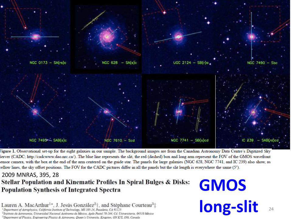
GMOS long-slit 24
2009 MNRAS, 395, 28

GMOS long-slit
25
2009 MNRAS, 395, 28

26
2009 MNRAS, 395, 28
GMOS long-slit
Spiral barred galaxy NGC 7741

GMOS multislit
• With a 5.5 arcmin field of view, 30-60 slits can typically be located in a single mask
• maximum of several hundred slits when using narrow-band filters
• Slit widths 0.5 arcsec or larger
• Masks designed from GMOS direct imaging
• Masks designed from object catalogs
• R (max) = 4000 ?
27

Object slits (white & yellow) with the alignment stars (cyan) , CCD gaps (blue) and the mask area (red) plotted over the GMOS pre-imaging. This plot is used to check the masks
28
GMOS multi-slit

DEIMOS (Keck II) DEep Imaging Multi-Object Spectrograph
29

30

DEIMOS (Keck II) • generous slit length spanning 16.6 arcmin on sky
(vs. 5,5 arcmin for Gemini GMOS)
• large 8k×8k detector mosaic featuring eight CCDs
• advanced, closed-loop flexure compensation system achieving image stability of ±0.25 px over 360° of instrument rotation
• wide spectral coverage (up to 5000 Å per exposure)
• high spectral resolution (up to R≈6000)
• multi-slit spectroscopy of 100+ resolved targets per mask or 1000+ targets with narrow-band filters
• convenient IDL-based data reduction pipeline 31

32
https://www2.keck.hawaii.edu/inst/deimos/gratings.html

33
https://www2.keck.hawaii.edu/inst/deimos/filter_list.html

Preparation
Up to four weeks before the run:
- Use the IRAF-based package DSIMULATOR to select targets from an astrometric catalog.
- Will be used to make the DEIMOS maks
34 https://www2.keck.hawaii.edu/inst/deimos/primer.html

35
https://www2.keck.hawaii.edu/inst/deimos/dsim.html
Parallactic angle h: position from the object to the Zenith slit aligned vertically to avoid losses in the blue-UV

Integral Field Spectroscopy (IFU)
36
Microlenses + fibers
slit Spectra on detector

GMOS IFU • Lenslet array (containing 1500 elements) in the
pre-slit slice the focal plane into many components.
• Each lenslet is coupled to a fiber.
• The fibers end at the slit of the spectrograph.
• The science field of view is 35 square arcsec (5"x7") and is sampled by 1000 elements. The sky is sampled by the remaining 500 elements which are located ~1 arcmin away from the science field
37

38

Multi-object spectroscopy with fibers
39
Slit
Spectra on CCD
M80 globular cluster
Good for not-so-close objects, allows to cover a wide field

Fibers are positioned using magnetic buttons
40
light

41
The 2dF robotic fibre positioner which feeds the AAOmega spectrograph is mounted at the prime focus on top of the AAT 3,9m telescope.
Spectrograph is at the coude room (38 m de fibras opticas)

42
The 2dF robotic fibre positioner The metal field plate is seen populated with fibre buttons which are used to relay the light from astronomical targets down to the AAOmega spectrograph. The robot gripper is seen hovering over a button which it is about to move to a new target position.

Old 2dF (one arm) Almost 400 spectra (200 in each CCD)
43

Latest 2dF AAOmega spectrograph (2005)
• 2 degree field of view (compare to 5 arcmin GMOS)
• About 400 fibers
• Two arms covering full optical range 370-850nm, or 470-950 nm at R ~ 1300
• Resolving power up to
R ~ 10 000 is possible but with
smaller spectral coverage
• Simultaneous robotic
configuration for next field
44

Almost 400 spectra for red arm (and 400 more spectra on blue side)
45

Sky subtraction with 2dF/AAOmega
46
espectro do céu
espectro do quasar após subtração do céu

Automatic reduction at 2dF AAOmega 400 blue spectra + 400 red spectra !
47
http://www.aao.gov.au/2df/aaomega/aaomega_2dfdr.html

48
http://adsabs.harvard.edu/abs/2012arXiv1205.1306L
AAOmega no telescópio AAT de 4m é mais produtivo que o FORS no VLT de 8m (campo de apenas 7’ x 7’)

49
Teff log g [Fe/H] Candidate Sun (2df): 5783, 4.41, 0.08 Subaru spectra: 5822, 4.31, 0.09

50

Confirmed members of cluster IC 4499
51

52

FLAMES (VLT/ESO) - Fibre Large Array Multi Element Spectrograph
• Field of view: 25 arcmin in diameter
• UVES mode is for high resolution
(R ~ 47 000) but only 8 objects
• GIRAFFE mode :
- MEDUSA submode up to 130 targets at R ~ 5600 - 25000
- IFU submode in small field 2x3arcsec
- ARGUS submode : larger IFU (12x7”)
• Simultaneous UVES + GIRAFFE ok
• Pipeline (automatic data reduction) 53

Fiber positioning at FLAMES (< 15 min while observations are being performed on the other plate)
54

55
FLAMES/Giraffe spectrograph with Ozpoz

56
View of the back of one Ozpoz plate where all the fibres are attached with magnetic buttons
http://www.eso.org/sci/facilities/paranal/instruments/flames/inst/Giraffe.html
Flat-field image in medusa mode with the same HR9 setup. Wavelenghts are increasing from right to left. The vertical axis gives the position along the slit.
Th-Ar calibration in medusa mode using the HR9 setup. Lambda increases from right to left. The Y- axis gives the position along the slit

57 2012A&A...538A.100L

58

59

60

Deciphering the star-formation scenario of the Sh2-296 nebula. Profa. Jane + Beatriz Fernandes
61
The Gemini GMOS fields (squares): Blue squares are used to indicate the new proposed observations, while green squares correspond to the fields for which the masks are ready. The red squares represent the fields where spectra have been previously acquired. BLACK CIRCLES: XXM fields (X-ray). CIRCLES: VLT/FLAMES field

Multi-object spectroscopy : which one? IFU ? Longslit ? Multislit? Multifiber?
62
Aglomerados Omega Cen (left) e 47 Tuc (right) são aprox. do tamanho angular da Lua cheia
GMOS IFU Field of view 5"x7"

63
Novas tecnologias: Digital Micromirror Devices (DMD)

64
A comparison between a MOS that uses a slit mask for target selection and a DMD-based MOS. (a) The essential layout of a MOS that has a conventional slit mask at the telescope focal plane. Two slits are shown, and their beams pass through a collimator, a grating, and a re-imager before the dispersed light is focused on a detector such as a CCD. The placement of optical elements and light rays, and the use of transmissive optics, was chosen for illustrative purposes only; for example, the beams would be much wider in a typical spectrograph, and the grating would usually be reflective. (b) The same as (a), but for a DMD-based MOS such as RITMOS. Here a micromirror array has replaced the slit mask, and two mirrors are shown deflecting their light towards the collimator, while the other mirrors are tilted at the opposite angle.

65

66
Top view of the optical bench of RITMOS. This CAD drawing of the main interior contains all mechanical elements visible from this direction except for a horizontal reinforcement brace and electrical and fiber-optic cables. The black rectangles are mounts for thin baffles which stand perpendicular to the page. The dashed lines indicate the
optical paths

67
http://www.gemini.edu/sciops/instruments/gifs/GMOX_Final_Report_Public.pdf

68
Final report, October 2015
Figure 1: Left: A 102 ˆ 102 portion of the Hubble Ultra Deep Field, with a prominent dual-nucleus galaxy. The image is rendered with the original 50 mas pixel sampling of ACS/WFC (courtesy Z. Levay, STScI). The vertical bars are intended to represent the spectra that can be obtained by GMOX, with smallest apertures comparable to the pixels of the HST cameras. This 10”ˆ10” field is approximately 150 times smaller than the actual field of view of GMOX, at Gemini f/16. Right: a sketch of the data obtained by GMOX at each pointing. Five detectors capture the full wavelength range from U to K, each one dispersed over about 25,000 pixels, for hundreds of targets spread over the GMOX field of view.

69
Digital Micromirror Devices (DMDs) used as slit selectors

70

71

72

73