AG083115 How to configure TIA Portal V13 SP1 to read ... · How to configure TIA Portal V13 SP1 to...
12
Siemens Level and Weighing 1954 Technology Drive, P.O. Box 4225 Peterborough, Ontario K9J 7B1 / Canada Tel.: (705) 745-2431 Fax: (705) 741-0466 www.siemens.com/sensorsystems AG083115 How to configure TIA Portal V13 SP1 to read acyclic data from MultiRanger/HydroRanger 200 HMI over SmartLinx PROFIBUS DPV1 Objective: Use acyclic communications through a SmartLinx PROFIBUS DPV1 communications module master to read/write data to MultiRanger/HydroRanger 200 HMI. Equipment Description MLFB Part Number SIMATIC S7300 TIA Portal Step7 V13 SP1 SmartLinx PROFIBUS DPV1 module MultiRanger/HydroRanger 200 HMI Code example for the S7300 S7-315 PLC 6ES7 315-2AG10-0AB0 PROFIBUS DPV1 module A5E35778741 While every effort was made to verify the following information, no warranty of accuracy or usability is expressed or implied. Notes A complete code example is available for the Siemens SIMATIC S7300 PLC. This guide is an addition to the application guide TIA Portal V13 MR_HR_ HMI. Please use the TIA Portal V13 MR_HR_ HMI application guide to set up the cyclic data before using this guide. This guide assumes the user is familiar with TIA Portal V13 SP1. Overview This application guide is an addition to the operating instructions for MultiRanger/HydroRanger 200 HMI. It focuses on the setup and configuration of the S7300, using specific functions in the PLC, SFC58 (WR_REC), and SFC59 (RD_REC), to access the MultiRanger/HydroRanger 200 HMI parameters. Acyclic communication through PROFIBUS DPV1 is designed to allow read/write access to the PROFIBUS slave device. During normal operation of a PROFIBUS network, data is exchanged cyclically between the master and slave devices. If an acyclic request occurs, the Class I master will pass the request to the slave device. After the cyclic data has been read from the slaves, the acyclic request is sent to the slave. The slave device will then process the request and respond in the current scan or the next scan. Acyclic requests are executed periodically because parameter data is not required as frequently as the cyclic data. The example below will show you how to read/write the quick start parameters in MultiRanger/HydroRanger 200 HMI. The PLC code example uses a timer interrupt, OB35 (TIMER_INTERUPT), to indirectly call SFC58 and SFC59. In this example, OB35 is executed every 100 ms. APPLICATION GUIDE
-
Upload
nguyenminh -
Category
Documents
-
view
307 -
download
3
Transcript of AG083115 How to configure TIA Portal V13 SP1 to read ... · How to configure TIA Portal V13 SP1 to...

Siemens Level and Weighing 1954 Technology Drive, P.O. Box 4225 Peterborough, Ontario K9J 7B1 / Canada
Tel.: (705) 745-2431 Fax: (705) 741-0466 www.siemens.com/sensorsystems
AG083115
How to configure TIA Portal V13 SP1 to read acyclic data from
MultiRanger/HydroRanger 200 HMI over SmartLinx
PROFIBUS DPV1
Objective:
Use acyclic communications through a SmartLinx PROFIBUS DPV1 communications module master
to read/write data to MultiRanger/HydroRanger 200 HMI.
Equipment Description MLFB Part Number
SIMATIC S7300
TIA Portal Step7 V13 SP1
SmartLinx PROFIBUS DPV1 module
MultiRanger/HydroRanger 200 HMI
Code example for the S7300
S7-315 PLC 6ES7 315-2AG10-0AB0
PROFIBUS DPV1 module A5E35778741
While every effort was made to verify the following information, no warranty of accuracy or usability is expressed or implied.
Notes
A complete code example is available for the Siemens SIMATIC S7300 PLC.
This guide is an addition to the application guide TIA Portal V13 MR_HR_ HMI. Please use the TIA Portal V13 MR_HR_ HMI
application guide to set up the cyclic data before using this guide.
This guide assumes the user is familiar with TIA Portal V13 SP1.
Overview
This application guide is an addition to the operating instructions for MultiRanger/HydroRanger 200 HMI. It focuses on the setup
and configuration of the S7300, using specific functions in the PLC, SFC58 (WR_REC), and SFC59 (RD_REC), to access the
MultiRanger/HydroRanger 200 HMI parameters.
Acyclic communication through PROFIBUS DPV1 is designed to allow read/write access to the PROFIBUS slave device. During
normal operation of a PROFIBUS network, data is exchanged cyclically between the master and slave devices. If an acyclic
request occurs, the Class I master will pass the request to the slave device. After the cyclic data has been read from the slaves,
the acyclic request is sent to the slave. The slave device will then process the request and respond in the current scan or the next
scan. Acyclic requests are executed periodically because parameter data is not required as frequently as the cyclic data.
The example below will show you how to read/write the quick start parameters in MultiRanger/HydroRanger 200 HMI. The PLC
code example uses a timer interrupt, OB35 (TIMER_INTERUPT), to indirectly call SFC58 and SFC59. In this example, OB35 is
executed every 100 ms.
APPLICATION GUIDE

How to configure TIA Portal V13 SP1 to read acyclic data from
MultiRanger/HydroRanger 200 HMI over SmartLinx PROFIBUS DPV1 APPLICATION GUIDE
AG083115 Page 2 of 12
Modifying GSD to perform Acyclic communication
To allow acyclic communications through a Class I master, you must change the C1 and C2 response timeout.
1) Open the GSD file, HMSB1813.gsd, in Notepad and change the C1 and C2 timeout as shown below.
2) Save the file.
Use this GSD file to configure hardware in Step7.
Slot index table
The parameters, or diagnostic information, in the PROFIBUS slave device are arranged in a standard way and are accessed
through the slot index table. The table defines where information is stored in the device and references the slot and index for a
parameter or diagnostic.

How to configure TIA Portal V13 SP1 to read acyclic data from
MultiRanger/HydroRanger 200 HMI over SmartLinx PROFIBUS DPV1 APPLICATION GUIDE
AG083115 Page 3 of 12
Adding MultiRanger/HydroRanger 200 HMI to the hardware configuration
To add the MultiRanger/HydroRanger 200 HMI to the hardware configuration, you will need to add the device to the network and
define the number of modules required. A module holds a group of parameters or diagnostic information for the device. The total
number of modules must match the number of modules in the slot index table. The number of bytes in each module must add up
to the total number of bytes used for cyclic data exchange. For the MultiRanger/HydroRanger 200 HMI, this is 19 words of input.
To confirm/define the number of modules required for hardware configuration:
1) In the Device view, highlight the Anybus module (module inside the MultiRanger/HydroRanger 200 HMI).
2) Ensure that the slot configuration has 6 modules, configured with a total of 19 words of input.
Slot / Module Description
1 Parameters for channel 1
2 Parameters for channel 2
3 Global parameters
4 Relays
5 Device
6 Echo profile (internal use)
NOTE: The number of modules used in the cyclic data configuration is related to the number of slots used for acyclic
communications. Therefore, in order to access all 6 acyclic slots, 6 modules must be used in the hardware configuration.

How to configure TIA Portal V13 SP1 to read acyclic data from
MultiRanger/HydroRanger 200 HMI over SmartLinx PROFIBUS DPV1 APPLICATION GUIDE
AG083115 Page 4 of 12
TIA Portal Step7 V13 example program
This example will show you how to read/write the quick start parameters for the MultiRanger/HydroRanger 200 HMI
by referencing the index from the slot index table. In the slot index table, the quick start parameters for point 1 start at
slot 1, index 50.
1) In step7 V13, add OB35.
2) Inside OB35, insert a network for SFC58 and SFC59.
OB35 will execute every 100 ms and call SFC58 and SFC59.
3) Read the quick start parameters from the MultiRanger/HydroRanger 200 HMI and move the data to DB1.
If M100.1 is closed, SFC59 is called and will write the parameters from DB1 quick start 2 to the
MultiRanger/HydroRanger 200 HMI.
The complete code for OB35 is shown below:
How to configure TIA Portal V13 SP1 to read acyclic data from
MultiRanger/HydroRanger 200 HMI over SmartLinx PROFIBUS DPV1 APPLICATION GUIDE
AG083115 Page 5 of 12
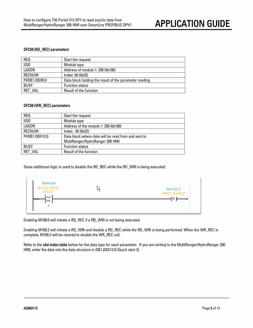
SFC59 (RD_REC) parameters
REQ Start the request
IOID Module type
LADDR Address of module 1: 256 (0x100)
RECNUM Index: 50 (0x32)
P#DB1.DBX0.0 Data block holding the result of the parameter reading
BUSY Function status
RET_VAL Result of the function
SFC58 (WR_REC) parameters
REQ Start the request
IOID Module type
LADDR Address of the module 1: 256 (0x100)
RECNUM Index: 50 (0x32)
P#DB1.DBX12.0 Data block where data will be read from and sent to
MultiRanger/HydroRanger 200 HMI
BUSY Function status
RET_VAL Result of the function
Some additional logic is used to disable the RD_REC while the RD_WRI is being executed.
Enabling M100.0 will initiate a RD_REC if a RD_WRI is not being executed.
Enabling M100.2 will initiate a RD_WRI and disable a RD_REC while the RD_WRI is being performed. When the WR_REC is
complete, M100.2 will be cleared to disable the WR_REC call.
Refer to the slot index table below for the data type for each parameter. If you are writing to the MultiRanger/HydroRanger 200
HMI, enter the data into the data structure in DB1.DBX12.0 (Quick start 2).

How to configure TIA Portal V13 SP1 to read acyclic data from
MultiRanger/HydroRanger 200 HMI over SmartLinx PROFIBUS DPV1 APPLICATION GUIDE
AG083115 Page 6 of 12
The data block (DB1) has the following structure:
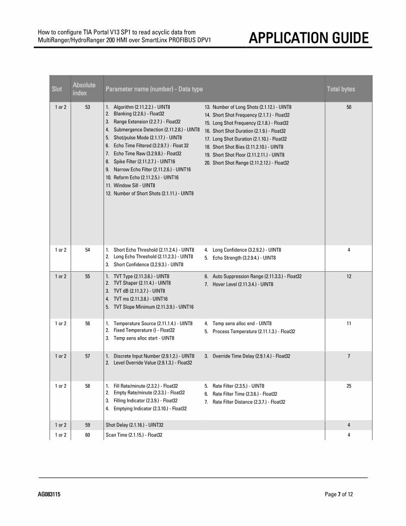
Slot index table
Slot Absolute
index Parameter name (number) - Data type Total bytes
1 or 2 50 1. Sensor Mode (2.1.3.) - UINT8
2. Material (2.1.6.) - UINT8
3. Rate Filter (2.3.5.) - UINT8
4. Transducer (2.1.5.) - UINT8
5. Empty (2.2.4.) - Float32
6. Span (2.2.2.) - Float32
12
1 or 2 51 1. Vessel Shape (2.7.2.) - UINT8
2. Maximum Volume (2.7.3.) - Float32
3. Dimension A (2.7.4.) - Float 32
4. Dimension L (2.7.5.) - Float 32
13
1 or 2 52 1. Fuzz Filter (2.11.5.6.) - UINT8
2. Echo Lock (2.11.5.4.) - UINT8
3. Echo lock up - UINT8
4. Echo lock down - UINT8
5. Echo Lock Window (2.11.5.5.) - UINT16
6
How to configure TIA Portal V13 SP1 to read acyclic data from
MultiRanger/HydroRanger 200 HMI over SmartLinx PROFIBUS DPV1 APPLICATION GUIDE
AG083115 Page 7 of 12
Slot Absolute
index Parameter name (number) - Data type Total bytes
1 or 2 53 1. Algorithm (2.11.2.2.) - UINT8
2. Blanking (2.2.6.) - Float32
3. Range Extension (2.2.7.) - Float32
4. Submergence Detection (2.11.2.8.) - UINT8
5. Shot/pulse Mode (2.1.17.) - UINT8
6. Echo Time Filtered (3.2.9.7.) - Float 32
7. Echo Time Raw (3.2.9.8.) - Float32
8. Spike Filter (2.11.2.7.) - UINT16
9. Narrow Echo Filter (2.11.2.6.) - UINT16
10. Reform Echo (2.11.2.5.) - UINT16
11. Window Sill - UINT8
12. Number of Short Shots (2.1.11.) - UINT8
13. Number of Long Shots (2.1.12.) - UINT8
14. Short Shot Frequency (2.1.7.) - Float32
15. Long Shot Frequency (2.1.8.) - Float32
16. Short Shot Duration (2.1.9.) - Float32
17. Long Shot Duration (2.1.10.) - Float32
18. Short Shot Bias (2.11.2.10.) - UINT8
19. Short Shot Floor (2.11.2.11.) - UINT8
20. Short Shot Range (2.11.2.12.) - Float32
50
1 or 2 54 1. Short Echo Threshold (2.11.2.4.) - UINT8
2. Long Echo Threshold (2.11.2.3.) - UINT8
3. Short Confidence (3.2.9.3.) - UINT8
4. Long Confidence (3.2.9.2.) - UINT8
5. Echo Strength (3.2.9.4.) - UINT8
4
1 or 2 55 1. TVT Type (2.11.3.6.) - UINT8
2. TVT Shaper (2.11.4.) - UINT8
3. TVT dB (2.11.3.7.) - UINT8
4. TVT ms (2.11.3.8.) - UINT16
5. TVT Slope Minimum (2.11.3.9.) - UINT16
6. Auto Suppression Range (2.11.3.3.) - Float32
7. Hover Level (2.11.3.4.) - UINT8
12
1 or 2 56 1. Temperature Source (2.11.1.4.) - UINT8
2. Fixed Temperature () - Float32
3. Temp sens alloc start - UINT8
4. Temp sens alloc end - UINT8
5. Process Temperature (2.11.1.3.) - Float32
11
1 or 2 57 1. Discrete Input Number (2.9.1.2.) - UINT8
2. Level Override Value (2.9.1.3.) - Float32
3. Override Time Delay (2.9.1.4.) - Float32 7
1 or 2 58 1. Fill Rate/minute (2.3.2.) - Float32
2. Empty Rate/minute (2.3.3.) - Float32
3. Filling Indicator (2.3.9.) - Float32
4. Emptying Indicator (2.3.10.) - Float32
5. Rate Filter (2.3.5.) - UINT8
6. Rate Filter Time (2.3.6.) - Float32
7. Rate Filter Distance (2.3.7.) - Float32
25
1 or 2 59 Shot Delay (2.1.16.) - UINT32 4
1 or 2 60 Scan Time (2.1.15.) - Float32 4

How to configure TIA Portal V13 SP1 to read acyclic data from
MultiRanger/HydroRanger 200 HMI over SmartLinx PROFIBUS DPV1 APPLICATION GUIDE
AG083115 Page 8 of 12
Slot Absolute
index Parameter name (number) - Data type Total bytes
1 or 2 61 1. Primary Measuring Device (2.13.2.) - UINT8
2. Flow Exponent (2.13.4.1.) - Float32
3. Maximum Head (2.13.4.2.) - Float32
4. Maximum Flow (2.13.4.3.) - Float32
5. Zero Head (2.13.4.5.) - Float32
6. Flow Time Units (2.13.4.4.) - UINT8
7. Flowrate Decimal (2.13.4.6.) - UINT8
8. Flowrate Units (2.13.4.7.) - UINT8
9. Low Flow Cutoff (2.13.4.8.) - Float32
24
1 or 2 62 1. mA Output Range (2.5.2.) - UINT8
2. Current Output Function (2.5.3.) - UINT8
3. mA alloc start - UINT8
4. mA alloc end - UINT8
5. 0/4 mA Level Value (2.6.2.) - Float32
6. 20 mA Level Value (2.6.3.) - Float32
7. Minimum mA Limit (2.5.7.) - Float32
8. Maximum mA Limit (2.5.8.) - Float32
20
1 or 2 63 1. Pump by Rate (2.8.1.8.) - UINT8
2. Level Setpoint Variation (2.8.2.6.2.) -Float32
5
1 or 2 64 1. Flow Maximum (3.2.6.15.) - Float32
2. Flow Minimum (3.2.6.16.) - Float32
8
1 or 2 65 1. Inflow/discharge Adjust (2.7.7.) - UINT8
2. Totalizer Multiplier (2.14.5.) - INT8
3. Totalizer Decimal Position (2.14.4.) - UINT8
4. Multiplier (2.10.1.2.) - INT8
5. Mantissa (2.10.2.2.) - Float32
6. Exponent (2.10.2.3.) - INT8
9
1 or 2 66 1. Space (3.2.6.11.) - Float32
2. Distance (3.2.6.12.) - Float32
3. Volume (3.2.6.5.) - Float32
4. Flow (3.2.6.14.) - Float32
5. Head (3.2.6.13.) - Float32
20
1 or 2 67 1. Level (3.2.6.3.) - Float32
2. mA value xducer - Float32
8
1 or 2 68 1. Transducer Temperature (3.2.6.17.) -
Float32
2. Transducer Temperature Maximum
(3.2.8.2.) - Float32
3. Transducer Temperature Minimum (3.2.8.3.) - Float32
12
1 or 2 69 1. Reading Maximum (3.2.6.8.) - Float32
2. Reading Minimum (3.2.6.9.) - Float32
8
1 or 2 70 Sensor Offset (2.2.5.) - Float32 4
1 or 2 71 Auto Sound Velocity (2.11.1.8.) - Float32 4
1 or 2 72 Auto Zero Head (2.13.3.) - Float32 4
1 or 2 73 1. Noise Average (3.2.9.5.) - UINT8
2. Noise Peak (3.2.9.6.) - UINT8
3. Noise minimum - UINT8
3

How to configure TIA Portal V13 SP1 to read acyclic data from
MultiRanger/HydroRanger 200 HMI over SmartLinx PROFIBUS DPV1 APPLICATION GUIDE
AG083115 Page 9 of 12
Slot Absolute
index Parameter name (number) - Data type Total bytes
1 or 2 74 1. Rate (3.2.6.6.) - Float32
2. Pump Records (3.2.7.) - Float32
8
1 or 2 75 Auto False Echo Suppression (2.11.3.2.) -
UINT8
1
1 or 2 77 1. LOE Timer (2.4.2.) - Float32
2. Fail-safe Mode (2.4.4.) - UINT8
3. Material Level (2.4.5.) - Float32 9
1 or 2 78 1. mA Fail-safe Mode (2.4.8.) - UINT8
2. mA Fail-safe Value (2.4.9.) - Float32
5
1 or 2 80-111 1. Breakpoint Level - Float32
2. Breakpoint Volume - Float32
8
1 or 2 112-151 TVT Shaper (2.11.4.) - INT8 1
1 or 2 152-157 PMD Dimensions (2.13.5.) - Float32 4
1 or 2 158-189 1. Head 1 (2.13.6.1.1.) - Float32
2. Flow 1 (2.13.6.1.2.) - Float32
8
3 50 Scan Time (2.1.15.) - Float32 4
3 51 1. Level (3.2.6.3.) - Float32
2. mA Value Transducer - Float32
8
3 52 1. Reading Maximum (3.2.6.8.) -Float32
2. Reading Minimum (3.2.6.9.) - Float32
8
3 53 1. Scaled mA Input Value (2.6.5.) - Float32
2. Raw mA Input Value (2.6.6.) - Float32
3. mA Input (3.2.6.19.) - Float32
12
3 54 1. mA Input Range (2.6.1.) - UINT8
2. 0/4 mA Level Value (2.6.2.) - Float32
3. 20 mA Level Value (2.6.3.) - Float32
4. mA Damp Filter (2.6.4.) - Float32
13
3 55-56 Discrete Input 1 Scaled State (2.9.2.3.) - Float32 4
3 57-58 Discrete Input 1 (2.9.2.1.) - UINT8 1
3 59 1. TS-3 Temperature (3.2.6.18.) - Float32
2. TS-3 Temperature Maximum (3.2.8.4.) -
Float32
3. TS-3 Temperature Minimum (3.2.8.5.) - Float32
3 63 1. LOE Timer (2.4.2.) - Float32
2. Fail-safe Mode (2.4.4.) - UINT8
3. Material Level (2.4.5.) - Float32 9
3 64 Milliamp Output (2.5.9.) - Float32 4
3 65-96 1. Breakpoint Level - Float32
2. Breakpoint Volume - Float32
8
3 97 1. Vessel Shape (2.7.2.) - UINT8
2. Maximum Volume (2.7.3.) - Float32
3. Dimension A (2.7.4.) - Float32
4. Dimension L (2.7.5.) - Float32
13

How to configure TIA Portal V13 SP1 to read acyclic data from
MultiRanger/HydroRanger 200 HMI over SmartLinx PROFIBUS DPV1 APPLICATION GUIDE
AG083115 Page 10 of 12
Slot Absolute
index Parameter name (number) - Data type Total bytes
3 98 1. Sensor Mode (2.1.3.) - UINT8
2. Material (2.1.6.) - UINT8
3. Rate Filter (2.3.5.) - UINT8
4. Transducer (2.1.5.) - UINT8
5. Empty (2.2.4.) - Float32
6. Span (2.2.2.) - Float32
12
4 50 Relay Duration (2.10.1.3.) - INT32 4
4 51 Preset Applications (2.8.1.3.) - UINT8 1
4 52 1. Run-ON Interval (2.8.2.7.1.) - INT32
2. Delay Between Starts (2.8.2.8.1.) - INT32
3. Power Resumption Delay (2.8.2.8.2.) - INT32 12
4 53-58 1. Service Ratio (2.8.1.12.) - Float32
2. Run-ON Duration (2.8.2.7.3.) - INT32
3. Pump Group (2.8.2.2.) - UINT8
4. Flush Pump (2.10.3.2.) - UINT8
5. Flush Cycles (2.10.3.3.) - UINT16
6. Flush Interval (2.10.3.4.) - UINT16
7. Flush Duration (2.10.3.5.) - UINT32
18
4 59-64 1. Level Source (2.8.1.2.) - UINT8
2. Relay Function (2.8.1.4.) - UINT8
3. ON Setpoint (2.8.1.5.) - Float32
4. OFF Setpoint (2.8.1.6.) - Float32
5. Relay Interval Setpoint (2.8.2.4.) - INT32
6. Relay Dead Band (2.8.2.5.) - Float32
7. Relay Logic (2.8.1.11.) - UINT8
8. Relay Fail-safe (2.8.2.3.) - INT8
20
4 65-70 Relay Logic Test (3.2.5.) - UINT8 1
4 71-76 1. Pump Run Time (3.2.7.3.) - Float32
2. Pump Hours (3.2.7.2.) - Float32
3. Pump Starts (3.2.7.4.) - UINT16
4. Pump Run-ONs (3.2.7.5.) - UINT16
12
5 50 1. Manufacturer string - n/a
2. DD_revision - n/a
41
5 51 Product - UINT8 1
5 52 1. Tag (3.1.1.) - UINT8
2. Message (3.1.3.) - UINT8
3. Descriptor (3.1.2.) - UINT8
4. Date Last Configured (3.1.10.) - UINT8
4
5 53 1. Manufacture Date (3.1.9.) - INT32
2. Serial Number Date - n/a
3. Serial Number Batch - n/a
4. Static Feature Status - INT32
5. Firmware Revision (3.1.7.) - UINT8
9
5 56 Write Protection (5.1.) - INT16 2
5 57 User PIN (5.2.) - INT16 2
5 58 1. Powered Days - INT32
2. Power ON Resets - UINT16
6

How to configure TIA Portal V13 SP1 to read acyclic data from
MultiRanger/HydroRanger 200 HMI over SmartLinx PROFIBUS DPV1 APPLICATION GUIDE
AG083115 Page 11 of 12
Slot Absolute
index Parameter name (number) - Data type Total bytes
5 59 1. Comm Bitrate - INT32
2. Comm Addr1 - INT32
3. Comm Addr2 - INT32
4. Comm Size1 - INT32
5. Comm Terminate - INT32
6. Comm Bist - UINT8
7. Comm Error - UINT16
8. Comm Error Count - INT32
9. Comm Fieldbus Interface - INT16
10. Comm Fieldbus Type - INT16
31
5 60 Diagnostic information (for testing) 240
5 61 1. Shot Synchro (2.1.13.) - UINT8
2. Scan Delay (2.1.14.) - UINT32
5
5 62 Units (2.1.1.) - UINT8 1
5 63 1. Default Auxiliary Reading (2.12.7.) - INT16
2. Auxiliary Value - n/a
2
5 64 Milliamp Output (2.5.9.) - Float32 4
5 65-68 mA Control Parameter - n/a 0
5 69-75 Comm Memory Map - UINT8 1
5 76-77 1. Communications Timeout (4.3.) - UINT16
2. Protocol (4.4.) - INT8
3. Device Address (4.2.) - INT32
4. Serial Baud Rate (4.5.) - Float32
5. Parity (4.6.) - UINT8
6. Data Bits (4.7.) - UINT8
7. Stop Bits (4.8.) - UINT8
8. Modem Available (4.9.) - UINT8
9. Modem Inactivity Timeout (4.10.) - UINT16
17
5 78 Parameter Index Location (4.11.) - UINT16 2
5 79-80 Communications Control (5.4.) - INT16 2
5 81 1. Soft Key - UINT16
2. Display Delay (2.12.8.) - Float32
3. Param Scroll Access - UINT8
4. Local Display Backlight (2.12.1.) - UINT8
5. Main Display - UINT8
9
5 82-84 1. Decimal Position (2.12.4.) - UINT8
2. Convert Reading (2.12.5.) - Float32
3. Offset Reading (2.12.6.) - Float32
9
5 88 1. Tag (3.1.1.) - UINT8
2. Message (3.1.3.) - UINT8
3. Descriptor (3.1.2.) - UINT8
4. Date Last Configured (3.1.10.) - UINT8
4

How to configure TIA Portal V13 SP1 to read acyclic data from
MultiRanger/HydroRanger 200 HMI over SmartLinx PROFIBUS DPV1 APPLICATION GUIDE
AG083115 Page 12 of 12
How to test using the watch table
1) Create a Watch table to test the read/write function.
2) Use Write Enable (M100.2) to enable the WR_REC and send the quick start parameters to the MultiRanger/HydroRanger
200 HMI.