
Afrox Product Reference Manual 12 |...
71
1 Afrox Product Reference Manual Welding Consumables Welding Consumables | Hardfacing | 12 Section 12 - Welding Consumables 1 Hardfacing 1 Hard Surfacing Definition 2 Choosing the Hardfacing Process 4 Processes Used in Hardfacing 5 General Hardfacing Data 7 Applying Hardfacing Materials 13 Wear Factors 17 Useful Hardfacing Data 23 Hardfacing Electrodes 27 Hardfacing Gas Assisted Wires 41 Hardfacing Open Arc Cored Wires 52 Hardfacing Submerged Arc Wires 64 Fluxes for Submerged Arc Welding 69 Hardfacing Gas Rods 70 | Hardfacing 12
-
Upload
duongkhanh -
Category
Documents
-
view
244 -
download
1
Transcript of Afrox Product Reference Manual 12 |...

1 Afrox Product Reference Manual
Wel
ding
Con
sum
able
s
Welding Consumables | Hardfacing |
12
Section 12 - Welding Consumables 1
Hardfacing 1
Hard Surfacing Definition 2
Choosing the Hardfacing Process 4
Processes Used in Hardfacing 5
General Hardfacing Data 7
Applying Hardfacing Materials 13
Wear Factors 17
Useful Hardfacing Data 23
Hardfacing Electrodes 27
Hardfacing Gas Assisted Wires 41
Hardfacing Open Arc Cored Wires 52
Hardfacing Submerged Arc Wires 64
Fluxes for Submerged Arc Welding 69
Hardfacing Gas Rods 70
| Hardfacing12

2Afrox Product Reference Manual
Wel
ding
Con
sum
able
s
| Welding Consumables | Hardfacing
12
Reasons for Hardsurfacing
Companies use hard surfacing products to:
1. Reduce costs - Hard surfacing a worn metal part to like new condition is usually 25 - 75% of the cost of a replacement part.
2. Prolong equipment life - Surfacing extends life 30 - 300 times, depending upon application, as compared to that of a non-surfaced part.
3. Reduce downtime - Because parts last longer, fewer shutdowns are required to replace them.
4. Reduce inventory of spare parts - There is no need to keep numerous spare parts when worn parts can be rebuilt.
Worn track rollers rebuilt by submerged arc hardfacing
Work railway tampers can be rebuilt by using manual or open arc processes
Now, on the side of reclaiming the part!
Reclaiming by hardfacing can often be done at a fraction of the cost of a new part.
It gives independence from shortages of spare parts thus reducing inventory and administration costs as well as eliminating waiting time for replacement components - greater efficiency.
Parts reclaimed by hardfacing are often better than new ones, just as a hardfaced component lasts from between two to twenty times longer than one that is not.
An added bonus of reclaiming by hardfacing is that in many cases the part can be rebuilt on site without the need for completely or even partly dismantling the machine.
Hardfacing worn components can save thousands of rands in maintenance costs.
Uses for Hardsurfacing
There are basically two main areas where hard surfacing is used:
1. To reclaim worn parts:
There is no known total solution to metal wear. Hence the stage must be reached when all components subject to wear will reach the limit of their useful life.
There are two avenues open to the plant engineer. Does he replace the part or does he reclaim it? To replace the part he must have it in stock or try to obtain a new one. The part may be expensive and if it requires frequent replacement a number must be kept on hand. This adds to the inventory costs and administration expenses of the business, aside from the actual cost of the replacement part.
In many cases, the part may be imported or not held in stock by the appropriate agents. Long delays can be involved - this means downtime of equipment and lost production.
Hard surfacing build-up can be used to return parts to their original dimensions
Hard surfacing overlay can be used by itself to give parts additional resistance to wear
Hard surfacing build-up and overlay can be used together to rebuild parts to size and give them additional resistance to wear
HARD SURFACING BUILD-UP HARD SURFACING OVERLAYHARD SURFACING OVERLAYHARD SURFACING BUILD-UP
BASE METAL BASE METAL BASE METAL
Hard surfacing is the deposition of a special alloy material on a metallic part, by various welding processes, to obtain more desirable wear properties and/or dimensions. The properties usually sought are greater resistance to wear from abrasion, impact, adhesion (metal-to-metal), heat, corrosion or any combination of these factors.
A wide range of surfacing alloys is available to fit the need of practically any metal part. Some alloys are very hard, others are softer with hard abrasion resistant particles dispersed throughout. Certain alloys are designed to build a part up to a required dimension, while others are designed to be a final overlay that protects the work surface.
Hard Surfacing Definition
Back to contents

3 Afrox Product Reference Manual
Wel
ding
Con
sum
able
s
Welding Consumables | Hardfacing |
12
Build-up. Steel mill roll rebuilt to original dimensions - it is being machined prior to service
Build-up. Worn rail end rebuilt past original dimensions - it will be ground prior to service
Overlay. Bucket lip hard surfaced as preventive maintenance
Overlay. Replacement dragline bucket tooth hard surfaced as new equipment
Then what of the quality of the replacement part? Will it last as well as is desired? Will it fit directly into the machine or will it require machining? Will adaptors have to be made or purchased so that it can be fitted to existing equipment?
2. The protection of new metal parts against the loss of metal.
Hard surfacing overlay is used on both new and/or original equipment where the part is most susceptible to wear. The higher alloy overlay offers much better wear resistance than that of the original base material. This usually increases the work life of the component up to two or more times that of a part which is not surfaced. Although the added hard surfacing material may add to the price of the equipment, usually a less expensive base material may be used.

4Afrox Product Reference Manual
Wel
ding
Con
sum
able
s
| Welding Consumables | Hardfacing
12
Nature of Work to be HardfacedHardfacing can be applied by a number of welding processes. In most cases, the equipment is identical or similar to that used for structural welding.
Selection of the most suitable welding process for a given job will depend on a number of factors including:
Base metal composition:Different processes may have different heat inputs which render them unsuitable for certain base metal types, e.g. manganese steels require low heat input and so gas hardfacing would not be suitable.
Size and shape:Surfacing large areas with gas or manual arc may often prove uneconomical. Parts of irregular shape may not be suitable for automatic applications.
Accessibility: It may not always be possible to manipulate heavy automatic equipment into areas where work must be done. Also, out-of-position welding will limit the choice of processes.
State of repair: Large badly worn components requiring heavy rebuilding would be best suited to processes with high deposition rates.
Number: If a large number of the same or similar items are to be hardfaced, an automatic process would be most suited.
Function of the component:i.e. What type of hardfacing alloy is required; some processes are limited to certain alloy types.
Choosing the Hardfacing Process
Back to contents

5 Afrox Product Reference Manual
Wel
ding
Con
sum
able
s
Welding Consumables | Hardfacing |
12
Shielded Metal Arc Welding (Covered Electrode)
Advantages
Alloy availability - most hard surfacing alloys are available as covered electrodes
Material thickness - within certain practical and economic limitations, most parts can be welded with the SMAW process
Welding position - hard surfacing covered electrodes are available for out-of-position work
Versatility - covered electrodes are capable of being used outdoors and in remote locations.
Disadvantages
Dilution - two or three layers are needed to obtain maximum wear properties
Low efficiency/deposition - stub loss and deposition of 0,5 - 3 kg/hr.
Shielded Metal Arc Welding (SMAW)
Flux Cored Arc Welding
Advantages
Alloy availability - almost as many alloys available as SMAW, with the ability to customise alloys easily if the demand requires
High deposition - rates ranging from 1,8 - 11,3 kg/hr
Deposit integrity - good recovery of elements across the arc
Easy to operate - minimal time is required to train an operator
Versatility - not as versatile as covered electrodes, but capable of being used outdoors and in remote locations due to open arc operation.
Disadvantages
Dilution - two or three layers are needed to obtain maximum wear properties
Welding position - although some wires have out-of- position capabilities, most are designed for flat and horizontal applications.
Open Arc Flux Cored Arc Welding (FCAW)
Submerged Arc Welding
Advantages
Easily automated - process lends itself to automatic application
High deposition - more economical to rebuild large worn parts
Operator skill - little skill is needed and training is minimal
Weld deposit - produces smooth, clean and sound weld deposits
Shop environment - no flashes since flux surrounds the arc.
Disadvantages
Alloy availability - limited to certain alloys that are commonly used for submerged arc rebuilding
Welding position - limited to flat position because of the flux shielding - usually limited to cylindrical parts
Material thickness - sub arc hard surfacing limited to larger parts that lend themselves to automatic application
Extremely high dilution - multiple layers are needed for maximum wear properties
High heat input - can distort parts
Versatility - limited to shop applications due to automatic equipment required
Flux required - additional expense and special welding equipment required.
Submerged Arc Welding (SAW)
Electrode covering
Core wire
Shielding atmosphere
Weld pool
Solidified slagMetal and slag droplets
Penetration depth
Base metal
Direction of welding
Arc shield composedof vapourised andslag forming compounds
Weld metal
Weld Pool
Solidified slag
Arc & metal transfer
Powdered metal, vapourforming materials,deoxidisers and scavengers
Weld pool
Tubular electrode
Direction of welding
Wire guideand contact tube
Moltenslag
To automatic wire feed
To flux hopper
Flux feed tube
Flux
Work connection
Base metal
Welding wire
To welder power
Contact
flux shelfSolid slagBead orfinishedweld metal
Welding vee
Weld backing plateTab
Weld travel
Processes Used in Hardfacing
Back to contents

6Afrox Product Reference Manual
Wel
ding
Con
sum
able
s
| Welding Consumables | Hardfacing
12
Welding Process Dilution Factors
Oxy-Acetylene 0 - 5 % Dilution
TIG Welding 5 - 15 % Dilution
Covered Electrode 20 - 45 % Dilution
Flux Cored Wire 20 - 45 % Dilution
Submerged Arc 25 - 50 % Dilution
For further information regarding dilution and its effect on wear resistance of hard surfacing deposits, see page 10.
Gas Hardfacing
Rod Deposition
This process uses alloyed hardfacing rods which may be cast, wrought or powder filled tubes. Standard gas welding equipment is used.
Advantages
Low dilution of deposit
Good control of deposit shape
Low thermal shock due to slow heating and cooling.
Disadvantages
Low deposition rates
High heat input
Not suited to large components.
Powder Spraying
Flame Spraying
This process involves spraying alloys in powder form onto the base component. The sprayed powder may then be fused to produce a strong bond and a dense, porous-free deposit.
Equipment used can be either hand held spraying torches or sophisticated metallising guns for more specialised applications.
Advantages
Precise control over deposit thickness and shape
Negligible dilution of deposit
Easy to use
Suitable for automation
Wide choice of coating materials available.
Disadvantages
High heat input with fused coatings.
High Velocity Oxy-Fuel Process (HVOF)
This process is similar to flame spraying except that the pressures used for the gas stream are much higher thus increasing the velocity of the gas leaving the nozzle. This allows for higher deposition rates than flame spraying.
Advantages
Precise control over deposit thickness and shape
Negligible dilution of deposit
Suitable for automation
Wide choice of coating materials available.
Disadvantages
Relatively high cost of equipment
Limited mobility.
Electric Arc Spraying
In arc spraying, a DC electric current is struck between two continuously fed consumable wires that make up the coating material.
A compressed gas is then injected through a nozzle atomising the molten wire and projecting it onto the work pieces.
Advantages
High deposition rates
Negligible dilution of deposit
Suitable for automation
Precise control over deposit thickness and shape.
Disadvantages
Limited mobility
Relatively high cost of equipment
Limited to consumables which will conduct current
Exposed electric arc.
Plasma Transferred Arc (PTA)
In plasma spraying, a DC electric current is used to generate a stream of ionised gas at high temperature. This ionised gas or plasma is the heat source, which then conducts the coating material, which is introduced into the plasma stream in the form of a powder onto the workpiece.
Advantages
Negligible dilution of deposit
Suitable for automation
Precise control over deposit thickness and shape
High melting point materials can be used.
Disadvantages
Limited mobility
Relatively high cost of equipment
Oxidation of the spray material may occur.

7 Afrox Product Reference Manual
Wel
ding
Con
sum
able
s
Welding Consumables | Hardfacing |
12
Weldability of Steels and IronsHardfacing can be applied successfully to a wide variety of base metal types. As with structural or repair welding, different types of base metals may require some adjustments to be made to standard welding practice. The following section discusses the various requirements of the different types of base metals. If in doubt about what type of metal a particular item is made from, refer to page 23. ‘Identification of Metals’ will prove helpful.
Mild Steel and Low Alloy Steels
This group of materials include plain carbon steels containing up to 0,3 carbon as well as the low alloy types which may include small amounts of elements such as manganese and chromium. Most of these alloys can be found in either wrought (rolled, forged, etc.) or cast form. In general, these steels can be welded without any special precautions, but for large sections or thicknesses over about 20 mm, a preheat of about 100°C will help to reduce any risk of stress cracking.
Hardenable Carbon and Alloy Steels
This group includes carbon steels with over 0,3 carbon as well as the alloy steels used for items such as cutting knives, dozer blades, certain bucket teeth, etc. It is always advisable to give steels in this group a preheat of 150 - 200°C before welding and then to allow the part to cool slowly under some form of insulation such as lime when the hardfacing is completed. Whenever possible, the preheat temperature should be maintained during the hardfacing operation. Under such circumstances, it is advantageous to perform all the welding required on an individual component in a short space of time without undue interruptions. Buffer layers may also be required on these steels for certain service conditions.
Tool Steels
Tool and die steels are often very susceptible to hot zone cracking due to the formation of untempered martensite during the hardfacing operation. To offset this, it is necessary to use a high preheat temperature, in the order of 500°C, and to maintain this temperature throughout the welding operation. Immediately after hardfacing, the part should be cooled very slowly by covering well with a good insulator such as dry powdered lime or vermiculite, or alternatively the part can be slowly cooled in a furnace.
Austenitic Stainless Steels
These materials can be hardfaced without any preheat but it is desirable to limit hardfacing to the weldable grades of stainless steels especially if the component is for use in corrosive environments. These grades either contain stabilisers such as titanium or are made with very low carbon contents. Austenitic stainless steels are more likely to suffer from distortion than are other types of steel and as such, it is desirable to keep heat input as low as practical during hardfacing.
Plain Chromium Stainless Steels
These can be either the hardenable martensitic types or the soft ferritic grades. Both can be hardfaced successfully. For the hard types, a preheat of about 400°C should be used followed by
slow cooling under insulation after hardfacing. The soft ferritic types require no preheat and heat input should be kept to a minimum during hardfacing to avoid excessive grain growth and consequent strength reductions.
Austenitic Manganese Steels
These steels, which contain 11 to 14% manganese, are very tough and strong with excellent resistance to impact. In fact, they have the ability to work harder under load which makes them very suitable for use in crushing equipment. They are almost inevitably encountered in the form of castings which will be non-magnetic or very feebly magnetic even after prolonged use.
Austenitic manganese steels should not be preheated except in very cold climates, when a warming to about 50°C may be used.
To avoid the possibility of forming brittle phases in the weld zone, heat input must be kept to an absolute minimum. Components made from 11-14% manganese steel should be kept cool during hardfacing either by immersing all but the working area in water or by welding intermittently. Frequent hosing with water is advisable where there is a danger of the weld zone exceeding a temperature of 300°C for any appreciable amount of time. Also, low amperages should always be used. The embrittlement of manganese steels is a time/temperature reaction (see overleaf). Higher carbon and lower manganese accelerates this reaction.
Manganese steels should never be hardfaced by gas flame processes due to the high heat input.
Grey Cast Iron
There are two techniques used for hardfacing cast iron. The first involves preheating to about 500°C under which circumstances large areas can be rebuilt or hardfaced with little risk of cracking. Cooling after welding should be slow and some form of insulation cover is generally used. Rebuilding or crack repair is best performed using a pure or high nickel electrode such as Ferroloid 4 and Ferroloid 3 or a low hydrogen mild steel electrode such as Afrox 7018-1. Similarly, gas processes may be used such as powder spraying.
The second technique is often used on large items which are not practical to preheat. It involves using the high alloy hardfacing electrodes which produce a high incidence of relief checks. High travel speeds and low currents are normally used to promote
1,2% - 13% Mn & 0,5% Si482
426
371
315
260
2040,1 1,0 10 100 1000
Time at temp. (Hours)
Embrittled
DuctileTem
p o C
General Hardfacing Data
Back to contents

8Afrox Product Reference Manual
Wel
ding
Con
sum
able
s
| Welding Consumables | Hardfacing
12
as much relief checking as is practical. The relief checks so produced reduce stresses in the weld area and ensure a sound overall job.
Note that for repair welding without preheat, Ferroloid 4 is recommended as the most appropriate electrode.
Ni-Hard Cast Irons
These are among the most difficult of materials to hardface, but a good degree of success has been achieved using the following procedure.
Firstly, the entire casting must be preheated to a dull red and this temperature must be maintained throughout the entire welding operation.
The area to be hardfaced must then be completely overlayed with pure nickel electrodes or nickel wire for gas shielded or sub arc welding.
Hardfacing is then applied over the top of the nickel using any hardfacing electrode suitable for the service conditions of the component.
After welding, the casting must be cooled very slowly from red heat under a cover of insulating material or in a furnace.
White Cast Iron
Hardfacing of white cast iron is not recommended.
Preparation for HardfacingSurface Condition
The first requirement is that the workpiece be clean and free of rust or heat scale. Wire brushing, grinding and/or solvent washing may be required to remove dirt, grease, rust, etc. The degree of cleanliness required is greater when gas hardfacing is to be used and for this process the job should always be dressed back to clean, shiny base metal.
A sound base is required and this may necessitate removing fatigued or rolled-over metal, high ridges, or other major surface irregularities. This may be done by grinding, machining or arc gouging.
Cracks in the base metal should be arc gouged or ground out and repaired using compatible electrodes.
When building up edges of cutting tools, dies, etc., a recess is required to provide adequate support for the hardfacing material.
Job Positioning
Wherever possible, the job should be positioned so that hardfacing can be performed in the downhand position (workpiece horizontal). An uphill inclination of about 10° can sometimes be of assistance in laying down heavier weld passes.
If work must be done out of position, detailed attention will have to be given to selecting suitable consumables and welding processes.
Preheating
The effect of preheating reduces the tendency to:
1. Develop cracks. Moisture may be brought into the molten weld metal by electrode coatings or fluxes. The hydrogen that is created from the moisture increases the chance of weld or heat affected zone cracking. Preheating slows
down the cooling rate which allows the hydrogen to escape.
2. Develop shrinkage stresses. Molten weld metal contracts while it cools, which causes stress to build up between the contracting weld metal and the cooler base metal. This can cause cracking during or after welding. By preheating the base metal, the temperature differential between the base metal and the weld metal is reduced. This will diminish the susceptibility to cracking.
3. Develop porosity. Again, hydrogen is the culprit. Moisture can be present on a non-preheated surface. During welding, hydrogen can be trapped in the weld metal and can cause porosity as it solidifies. Preheating will eliminate moisture on a base material.
4. Develop hard zone adjacent to welds. Some alloy steels have a tendency to become hard and crack in the heat affected zone due to the fast cooling rates during welding. Preheating slows the cooling rate and provides a more ductile microstructure.
5. Develop distortion. As weld metal cools, it contracts and develops stresses between the weld metal and the cooler base metal. The base metal then can become permanently distorted. Preheating can help minimise distortion by reducing the temperature differential between the base metal and the weld metal.
How are preheat temperatures determined?
Base material chemistry must be known before an accurate preheat temperature can be selected. The carbon content and alloy content of the base metal are two major factors that affect preheat temperatures.
Normally, the higher the carbon content and/or the higher the alloy content, the higher the preheating temperature. During welding, the interpass temperature should be the same as the preheat temperature.
Another major factor in determining preheat temperatures is the base metal thickness. As the base metal increases in thickness, a higher preheat temperature is needed.
When preheating, a soaking preheat is required to bring the entire component to the given preheat temperature. Usually all components that are preheated should be slow cooled.
The Use of Buffer Layers
The term buffer is used to describe the presence of an intermediate deposit laid between the base metal and the actual hardfacing weld material.
There are a number of cases where this practice is necessary.
1. Hardfacing on soft material for high load service.
When the ‘harder’ hardfacing materials are used on a soft base material, e.g. mild steel, there will be a tendency for the hardfacing layer to sink in under high load condition. This may result in spalling off of the hardfacing material under extreme conditions.
To overcome this, a layer of strong, tough material is deposited on the workpiece prior to hardfacing. Suitable buffering materials for such work would be Afrox 300 or Afrox 312, Tube Alloy AP-O, Corewear 34-O, Tube Alloy Build-Up-O and Corewear 31-S.

9 Afrox Product Reference Manual
Wel
ding
Con
sum
able
s
Welding Consumables | Hardfacing |
12
2. Hardfacing on components subject to heavy impact or flexing.
Many hardfacing deposits contain ‘relief checks’.
When a component is subject to heavy impact or flexing, there is the risk that even deposits which do not relief check during welding will develop fine transverse cracks. These are not detrimental to the hardfacing but there is a danger that under such service conditions, the cracks will act as stress concentrators and progress through into the base metal. This tendency is most pronounced where the base metal is a high strength steel.
The use of a suitable buffer layer between the base and hardfacing deposit will prevent this crack propagation from occurring. Suitable materials for this work are Afrox 312, or for use on alloy steel base metals, a low hydrogen electrode such as Afrox 7018-1 will prove reliable.
3. Hardfacing over partly worn hardfacing.
It frequently happens that components which have previously been hardfaced have worn through in certain areas and some of the original hardfacing material is still remaining.
In many cases, it is possible to re-apply hardfacing deposits directly over this existing material, especially types suitable for multi-layering and if it has not been fractured by heavy impact. If this is not so, it is necessary to take some action to prevent subsequently applied hardfacing material from ‘spalling off’.
The best technique is to gouge out the remaining doubtful hardfacing material. If however, it is impractical to do this, a buffer layer of Afrox 312 or Afrox 7018-1 between the two deposits will secure the existing hardfacing and produce a very tough base metal for the final hardfacing layers.
Controlling Distortion
Distortion is present to some degree in all welding and in many cases it is not severe enough to be of any consequence. There are, however, a number of instances where it can cause problems in hardfacing, especially on thin base metal sections.
Distortion is caused by two prime factors:
1. Contraction of the weld metal during cooling from the molten state to ambient temperature.
Molten metal contracts or shrinks approximately 11% in volume on cooling to room temperature. In hardfacing, the molten weld metal bonds to the parent metal and during its shrinkage tends to pull it in an arc along the direction of the weld run.
2. Different rates of expansion and contraction between the metal adjacent to and at a distance from the weld.
This problem is most accentuated in very thin base metal thicknesses. The metal close to the weld zone becomes very hot and starts to expand. Being restrained by the cold hard metal further out from the weld zone, it could only move by pushing out or buckling the plastic area around the weld. Once sufficient movement has taken place, it cannot be fully reversed during the cooling cycle and the job may remain permanently distorted.
There are a number of ways distortion can be controlled or at least kept to a minimum during hardfacing.
1. Using hardfacing alloys that relief check.
Many of the high alloy hardfacing materials relief check on cooling. This means that small cracks are formed across the weld bead so as to break up and reduce the amount of stress or pull that the cooling weld metal exerts on the base material.
These relief checks are in the vast majority of cases not detrimental to the performance of the hardfacing deposit and do not cause spalling and flaking. Relief checking tendency is increased by low welding currents and high travel speeds.
2. By restraining of parts.
In many cases distortion, especially of the first type discussed, can be overcome by restraining the part so that it is not free to move. This can be done by clamping or tack welding the part to a firm support. For flat items such as crusher jaws, etc. two parts can be clamped or tack welded back to back and hardfacing applied to each alternately.
3. By presetting.
By presetting or prebending the part in the opposite direction to that which it would distort, the welding will tend to pull it back to its original form. The amount and actual nature of the presetting required for a given job will be best established by experience.
10Afrox Product Reference Manual
Wel
ding
Con
sum
able
s
| Welding Consumables | Hardfacing
12
4. By preheating.
By slowing down the cooling rate and thus the rate at which hot metal contracts, preheating can sometimes be used to reduce distortion. This is because it allows more time for stresses to become equalised in areas immediately adjacent to the weld rather than distorting the overall job.
5. By correct welding sequence.
The use of intermittent welding techniques such as back stepping can help greatly in reducing distortion on flat items such as bulldozer and grader blades.
Also as mentioned earlier, if two items are fixed back to back and the hardfacing performed alternately on each, the distortion is minimised. This technique is often used on crusher jaws and other large flat items.
NOTE: When hardfacing long thin components such as guillotine blades, there is a strong likelihood that there will be some shrinkage of the base metal which will result in the blade becoming shorter. This can be largely overcome by restraining the blade but even so, it is advisable to make some allowance for shrinkage when cutting material for new blades.
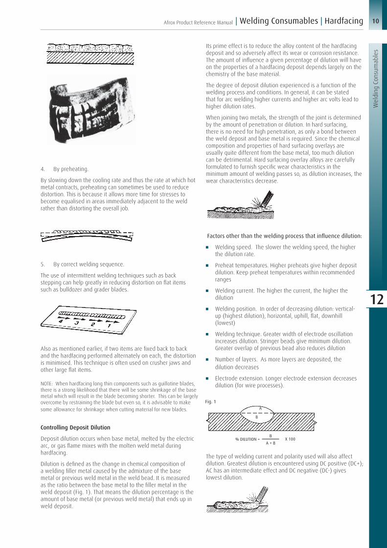
Controlling Deposit Dilution
Deposit dilution occurs when base metal, melted by the electric arc, or gas flame mixes with the molten weld metal during hardfacing.
Dilution is defined as the change in chemical composition of a welding filler metal caused by the admixture of the base metal or previous weld metal in the weld bead. It is measured as the ratio between the base metal to the filler metal in the weld deposit (Fig. 1). That means the dilution percentage is the amount of base metal (or previous weld metal) that ends up in weld deposit.
Its prime effect is to reduce the alloy content of the hardfacing deposit and so adversely affect its wear or corrosion resistance. The amount of influence a given percentage of dilution will have on the properties of a hardfacing deposit depends largely on the chemistry of the base material.
The degree of deposit dilution experienced is a function of the welding process and conditions. In general, it can be stated that for arc welding higher currents and higher arc volts lead to higher dilution rates.
When joining two metals, the strength of the joint is determined by the amount of penetration or dilution. In hard surfacing, there is no need for high penetration, as only a bond between the weld deposit and base metal is required. Since the chemical composition and properties of hard surfacing overlays are usually quite different from the base metal, too much dilution can be detrimental. Hard surfacing overlay alloys are carefully formulated to furnish specific wear characteristics in the minimum amount of welding passes so, as dilution increases, the wear characteristics decrease.
Factors other than the welding process that influence dilution:
Welding speed. The slower the welding speed, the higher the dilution rate.
Preheat temperatures. Higher preheats give higher deposit dilution. Keep preheat temperatures within recommended ranges
Welding current. The higher the current, the higher the dilution
Welding position. In order of decreasing dilution: vertical- up (highest dilution), horizontal, uphill, flat, downhill (lowest)
Welding technique. Greater width of electrode oscillation increases dilution. Stringer beads give minimum dilution. Greater overlap of previous bead also reduces dilution
Number of layers. As more layers are deposited, the dilution decreases
Electrode extension. Longer electrode extension decreases dilution (for wire processes).
The type of welding current and polarity used will also affect dilution. Greatest dilution is encountered using DC positive (DC+); AC has an intermediate effect and DC negative (DC-) gives lowest dilution.
A
Fig. 1
B
% DILUTION = X 100B
A + B

11 Afrox Product Reference Manual
Wel
ding
Con
sum
able
s
Welding Consumables | Hardfacing |
12
Gas rod hardfacing and powder spray processes have by far the lowest dilution rates due to only very limited melting of the base metal during deposition.
Fig. 2
DC+
AC
DC-
Schematic representation of dilution effects resulting from different welding polarities
Hardfacing Deposit Patterns
Hardfacing deposits will generally be applied in one of three patterns. These are continuous cover, stringer beads or individual dots. The selection of which type of deposit is best suited will depend on a number of factors including function of the component, service conditions and state of repair.
Continuous Coverage
This will generally be used for rebuilding and hardfacing parts that have critical size or shape, such as rolls, shafts, tracks, crusher jaws and cones.
Continuous cover is often required on parts subject to high degrees of fine abrasion or erosion. Typical examples would be pump and fan impellers, sand chutes, valve seats, dredge bucket lips and pug mill augers.
Care should be taken that sufficient overlapping of weld runs is allowed to ensure adequate coverage of the surface being treated. For protection against fine abrasion or erosion, it is desirable to have the weld runs at right angles to the direction of travel of the abrasive material.
Stringer Beads
Stringer beads are often used when it is not necessary to completely cover the base material. Typical examples would be dragline buckets and teeth, ripper teeth, rock chutes, etc. When depositing stringer beads, a weave technique is often used depending on requirements and base metal type.
There are a number of ways that stringer bead hardfacing can be applied depending on the working conditions of the component. This is best illustrated by considering the three following patterns as applied to ripper teeth.
For teeth working in coarse rocky conditions, it is desirable to deposit the stringer beads so that they run parallel to the path of the material being handled. This causes the large lumps of rock, etc. to ride along the top of the hardfacing beads without coming in contact with the base metal.
For teeth working in fine sandy conditions, the stringer beads will be placed at right angles to the direction of travel. This permits the fine material to compact in the intermediate spaces and provide protection to the base material.
Most earth-moving equipment is required to operate under conditions where there will be a mixture of coarse and fine abrasive material contacting the surface. For this type of service, a combination pattern known as a ‘checker’ or ‘waffle’ pattern is generally used.

12Afrox Product Reference Manual
Wel
ding
Con
sum
able
s
| Welding Consumables | Hardfacing
12
Dot Pattern
For less critical wear areas such as along the rear of buckets and shovels, etc. a dot pattern is often used. This is done by depositing the hardfacing alloy in small dots (15 - 20 mm dia. x 10 mm high) at about 50 mm centres over the surface. Also useful on large manganese castings to keep down heat input. Whilst not as effective as a ‘waffle’ pattern, it does allow fine material to compact between the dots whilst the high spots offer protection against large lumps or rocks.
Surface Finish
Will the deposit be machined? Ground? Flame cut? Must the component be heat treated? Are relief checks acceptable?
These questions should be answered before an alloy is selected:
Hard surfacing usually produces the finished surface of a component. If a smooth surface is required for the intended service, the possibility and economics of grinding or machining must be taken into account. Some alloys can be heat treated to soften them enough for machining and then heat treated back to a hardness suitable for maximum service life. Some applications, like rock crushing, may intentionally lack smoothness to aid in gripping incoming material.
In the carbide family of hard surfacing alloys, some alloys are by design crack sensitive and will develop stress relieving checks or cracks in the weld deposit as it cools (see photo below). These cracks are necessary to prevent spalling and do not weaken or affect the wear characteristics of the alloy. Usually, the lower the percentage of carbides in an alloy, the less likely relief cracks will occur. But the lower the carbide percentage in the alloy, the lower the abrasion resistance.
Stress relief cracks in a high chrome carbide overlay
Since hard surfacing alloys range from easily machinable to difficult to grind, the required finish must be determined prior to choosing an alloy. Often some sacrifice in wear resistance must be made to be able to achieve the required surface finish. Check specific product specifications to make sure the required finish is achievable.

13 Afrox Product Reference Manual
Wel
ding
Con
sum
able
s
Welding Consumables | Hardfacing |
12
Electric Arc HardfacingAs discussed earlier, there are a number of electric arc welding processes applicable to hardfacing. These are manual arc, semi-automatic and fully automatic open arc and submerged arc.
One important fact to remember when arc hardfacing by any of the above processes is the positioning of the work return lead. Arc welding requires a complete electrical circuit whereby the welding current can flow from the power source, across the arc and back to the power source again.
When hardfacing is to be performed on any machinery, the work return lead must be contacted as directly as possible onto the actual area being welded. If this is not done, there is a grave risk of arcing or electrical interference in other parts of the machinery which can cause extensive damage.
Take for example a bulldozer blade which is being hardfaced while still on the tractor. If the work return lead were clamped to the track instead of directly on the blade, the welding current may travel through bearings, rolls, transmission and other parts of the machine including generators and control equipment. By secondary arcing in these areas, a great deal of damage can be done to the machinery.
Manual Arc Hardfacing
The lowest welding current that will give good arc stability should be used for depositing hardfacing electrodes. Excessively high amperages result in deep penetration and undue dilution of the deposit. For higher deposition rates or heavier deposit thickness, it is always advisable to go to a larger size electrode rather than just increase welding current.
Recommended amperage usages for each electrode are printed on the electrode packets.
It is acceptable practice to apply hardfacing electrodes using a weave of three to four times the diameter of the electrode for downhand welding. For vertical welding, this may be increased to even double these limits but it should be noted that only a limited number of hardfacing electrodes are suitable for out of position welding.
Reducing the rate of forward travel between weaves increases the deposit thickness. The width of the weave should be reduced to one or two times the diameter of the electrode and travel speed increased when heat input is to be kept to a minimum or when a high degree of relief checking is required. Typical examples would be hardfacing the 11-14% manganese steels or hardfacing grey cast iron without the use of preheating.
Some electrodes are not recommended for multi-layer applications due to a tendency of such deposits to spall or flake.
For building up the edge of a component such as a shear or guillotine blade, a strip of copper or carbon block may be placed along the working edge. This chills the slag and weld metal giving a good contour to the weld deposit.
For most hardfacing, the electrode should be held at an angle of between 60 - 80° to the workpiece. This will give good deposit shape and allow adequate control of the molten metal.
It should be remembered that most hardfacing electrodes run in a somewhat different manner to structural welding types. All tubular hardfacing electrodes have a globular type transfer which helps minimise deposit dilution. Also, most of the higher alloy types do not give a complete slag cover over the weld. In many such cases, it is possible to do multi-layer work without removing slag residues from previous runs.
Semi-Automatic Open Arc Hardfacing
Most of the details regarding welding currents, weave techniques, etc. as discussed for manual arc welding apply to this process.
In general, comparatively high amperages are used for open arc welding and accordingly heat input rate is higher than for manual arc welding. For this reason it is necessary to use high travel speeds with very little or no weave when heat input is to be kept low. For work on small 11 - 14% manganese steel components, where there is not sufficient base metal section to give rapid heat dissipation, frequent water spraying is recommended.
12-60 mm
For most work, a 12 - 60 mm wire stick out depending on wire size should be used. The wire should be kept at an angle of 60 - 80° from the workpieces and the shortest arc length consistent with stable arc conditions used. Open arc welding is not considered to be very suitable for out of position welding and for this reason, all work should be done downhand where possible.
Care should be taken that wire drive rolls are set to the correct tension so as to provide positive drive but not so tight that they may deform the wire. All conduits from the drive rolls to the
Applying Hardfacing Materials
Back to contents

14Afrox Product Reference Manual
Wel
ding
Con
sum
able
s
| Welding Consumables | Hardfacing
12
gun should be kept as straight as possible with no twists, coils or kinks which would interfere with the wire feed. Contact tips, etc. should be kept clean and free from excessive build-up.
Many open arc hardfacing wires give a distinctly globular type transfer when used within the specified welding conditions. This is normal and desirable. Increasing current or voltage to try to achieve a spray type transfer similar to that of MIG welding is not advisable as excessive dilution of the deposit will occur and result in reduced wear resistance.
Most of the higher alloy tubular wires give incomplete slag cover of the weld. This is normal and it is often possible to do multi-layer work without removing residue from previous passes.
Automatic Open Arc Hardfacing
This process is almost identical to the semi-automatic open arc type except that the welding torch is mounted on a fixture to allow mechanical control.
The welding gun, which may be somewhat different in construction to those used for the semi-automatic process, may be either fixed, with the work mechanically driven under it, controlled to move over a stationary workpiece, or a combination of both of these.
In most cases, the unit will be set up so as to give an angle of about 75° between the wire and the job.
Automatic Submerged Arc Hardfacing
In submerged arc hardfacing the electric arc travels across the gap between the wire and the job under a cover of granulated flux.
The alloy additions necessary for a hard deposit may come either from the welding wire in which case a neutral shielding flux would be used or alternatively a mild steel filler wire is used and the alloys are introduced by way of a specially formulated flux. When using alloyed wire and a neutral flux, the deposit characteristics in terms of hardness and wear resistance are not greatly influenced by minor variations in welding conditions.
Weld Casting Manual arc or semi-automatic open arc welding can be very successfully used to apply heavy deposits of hardfacing materials by the weld casting technique.
This is often used to rebuild items such as mill hammers or to deposit heavy wear pads on large components.
For most work, a heavy split copper mould is made which fits around the area to be built up. This can be stripped off after welding. For wear pads, a mould may be produced by welding a series of stringer beads one over the top of the other to produce a dam of the required height. Alternatively, a short length of round or square pipe may be tack welded onto the job to act as a mould.
The hardfacing material is then cast directly into the mould using a normal manual arc electrode or continuous wire under high amperage conditions. The resulting deposit will have a sound homogeneous structure free from relief checks and with no tendency to spall or flake.
Semi-automatic open arc welding is the more satisfactory process for weld casting due to the continuous wire feed giving uninterrupted welding and the low volume of slag that is produced. Larger diameter manual arc electrodes, e.g. 5 mm and above will give good results provided changes of electrodes are fairly quick.
Weld casting can be used to produce deposits of up to 150 cubic cm without any difficulty by stick electrodes or wire techniques, e.g. 100 mm x 70 mm pads 20 mm thick or 70 mm diameter x 40 mm thick.
Having positioned the mould in the required place, the arc is struck onto the base metal and weaved as quickly as possible over most of the area to be covered. The electrode or wire is then oscillated quickly over the top of the weld metal as it builds up taking care to keep the heat as uniform as possible. When the mould is filled, the entire surface should be at bright red to white heat.
With proper technique and some puddling of the electrode, all slag should be floated above the weld metal leaving a sound dense deposit.

15 Afrox Product Reference Manual
Wel
ding
Con
sum
able
s
Welding Consumables | Hardfacing |
12
Due to the high heat input, weld casting is not recommended for use on 11-14% manganese steels. Also, on light sections there is a risk of excessive distortion around the weld pad.
Gas HardfacingRod Deposition
The practice of hardfacing by rod deposition can be likened in many ways to braze welding. The following is a step-by-step guide to the sequence of operations necessary to perform a successful hardfacing operation. This procedure can be used for all gas hardfacing rods except composite rod.
Surfaces should be cleaned of all dirt, rust, etc. For deposits along edges, prepare a recess as shown opposite.
Where necessary, preheat the job to the required level - refer page 8.
Using a tip one or two sizes larger than would normally be applied for welding a similar sized item; adjust gas flow to produce a soft 2 - 3X carburising flame.
Set the job up with a slight downhill slope for thin deposits or a slight uphill slope for thick deposits.
With the inner cone of the flame held about 3 mm from the surface of the job, heat a small area at the start of the run until the surface begins to sweat, i.e. takes on a wet appearance. The rod should be held in the flame envelope to preheat the end.
When the surface sweat is achieved over an area of about 10 to 15 mm in diameter, touch the end of the rod on to the sweating area, and melt off a small portion with the flame. Then raise the rod slightly away from the inner cone and heat the deposited globule of hardfacing material until it flows evenly over the surface to the required thickness.
Taking care that the surface ahead of the deposited metal is sweating, lower the rod into the leading edge of the deposited puddle and make further additions as the surfacing operation progresses. When a run has been completed, withdraw the flame slowly from the surface, using a slight circular movement. This tends to lessen any cratering that may form at the end of a run.
When the deposit is complete, edges, corners, etc. may be re-melted to facilitate smoothing of the surface.
Slowly cool the completed job.
Note for Hardfacing Cast Iron
Since cast iron does not sweat on heating, as does steel, a slight surface melt is necessary. Care must be taken not to overheat the casting as this would result in excessive dilution of the hardfacing alloy. Any surface crust that forms should be broken with the end of the rod. Deposition of a thin preliminary run followed by a second heavier one is desirable. Use of cast iron welding flux may also be advantageous.
Powder SprayingHand Torch Procedure
By following the simple step-by-step procedure outlined below, even inexperienced operators can achieve good results with a little practice.
1. Make sure that the surface to be treated is completely clean and de-greased. Grinding or sandblasting helps produce better bonding.
2. Lightly preheat the job with the torch to about 250 - 300°C (just light blue colour).
3. Spray the first layer of powder lightly and rapidly over the surface to produce a very thin coating of alloy. This is to prevent the low alloy base material from oxidising when the work is brought to red heat.
4. Do the facing run in small sections: heat a small area of the work with the torch until the surface begins to show signs of sweating, then spray a small amount of powder on to the surface and hold the flame there until the material melts. Repeat this procedure as you travel along the work. For large surfaces, a weaving action is recommended, with a travel of between 25 and 35 mm. Introduce the powder on the outward weaving motion, then apply heat alone on the inward motion. Do not try to heat too large an area at once, as this tends to overheat the job and cause the hardfacing deposit to boil and bubble.
The depth of deposit is governed by the quantity of powder delivered to the flame. The amount of depression of the lever determines the powder flow:
Slight depression gives a small flow, full depression gives maximum flow. Use a neutral flame.
Gun Spraying
The procedure for gun spraying varies considerably, depending on the type of equipment being used. The following is a brief guide only and should be used in conjunction with the gun manufacturer’s recommendations.
1. Prepare the surface by rough threading or grit blasting. It is most important that the surface be free of oil, dirt, etc. Consequently, machining lubricants should not be used and blasting grit must be clean and uncontaminated.

16Afrox Product Reference Manual
Wel
ding
Con
sum
able
s
| Welding Consumables | Hardfacing
12
2. Preheat the job to about 100 - 150°C. This is generally done with the job in position, e.g. spinning in a lathe. The flame of the spraying gun is often used for preheating.
3. With gas flows, surface speed of work, and powder metering valves set to the equipment manufacturer’s recommendations, open the powder control valve and commence spraying. Continue spraying until the required thickness of build-up is achieved, plus allowance for machining and about 15% shrinkage on fusing.
As it is necessary to limit surface temperature during coating, intermittent spraying may be necessary.
4. Remove the spraying gun and fuse the deposit using a multi-hole heating torch adjusted to give a soft, neutral to slightly reducing flame. Normal practice is to preheat the job to 400 - 500°C, then bring the heating torch to within 25 to 50 mm of the surface. When the deposit is properly fused, it takes on a wet, glossy appearance.
5. Allow the job to cool slowly.
17 Afrox Product Reference Manual
Wel
ding
Con
sum
able
s
Welding Consumables | Hardfacing |
12
The wearing of metal parts might be defined as a gradual decay or breakdown of the metal. When a part becomes so deformed that it cannot perform adequately, it must be replaced or rebuilt. While the end results of wear are similar, the causes of wear are different. It is essential to understand the wear factors involved before making a hard surfacing product selection.
It would be easy to select a surfacing alloy if all metal components were subjected to only one type of wear. However, a metal part is usually worn by combinations of two or more types of wear. This makes an alloy selection considerably more complicated.
A hard surfacing alloy should be chosen as a compromise between each wear factor. The initial focus should centre on the primary wear factor and then the secondary wear factor(s) should be examined. For example: upon examining a worn metal part, it is determined the primary wear factor is abrasion and the secondary wear factor is light impact. The surfacing alloy chosen should have very good abrasion resistance but also have a fair amount of impact resistance.
There are five major types of wear:
Abrasive (3 categories)
Impact
Adhesive
High temperature
Corrosive.
1. Abrasive wear - Abrasive wear is caused by foreign materials rubbing against a metal part. It accounts for 50 - 60% of all wear on industrial metal components.
Abrasive wear is really a group of wear problems. It can be broken down into three main categories:
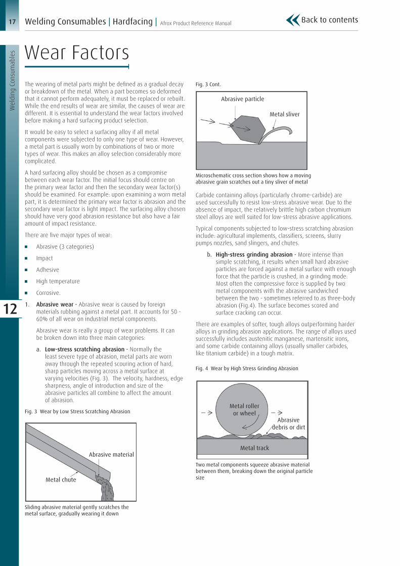
a. Low-stress scratching abrasion - Normally the least severe type of abrasion, metal parts are worn away through the repeated scouring action of hard, sharp particles moving across a metal surface at varying velocities (Fig. 3). The velocity, hardness, edge sharpness, angle of introduction and size of the abrasive particles all combine to affect the amount of abrasion.
Fig. 3 Wear by Low Stress Scratching Abrasion
Sliding abrasive material gently scratches the metal surface, gradually wearing it down
Abrasive material
Metal chute
Fig. 3 Cont.
Carbide containing alloys (particularly chrome-carbide) are used successfully to resist low-stress abrasive wear. Due to the absence of impact, the relatively brittle high carbon chromium steel alloys are well suited for low-stress abrasive applications.
Typical components subjected to low-stress scratching abrasion include: agricultural implements, classifiers, screens, slurry pumps nozzles, sand slingers, and chutes.
b. High-stress grinding abrasion - More intense than simple scratching, it results when small hard abrasive particles are forced against a metal surface with enough force that the particle is crushed, in a grinding mode. Most often the compressive force is supplied by two metal components with the abrasive sandwiched between the two - sometimes referred to as three-body abrasion (Fig.4). The surface becomes scored and surface cracking can occur.
There are examples of softer, tough alloys outperforming harder alloys in grinding abrasion applications. The range of alloys used successfully includes austenitic manganese, martensitic irons, and some carbide containing alloys (usually smaller carbides, like titanium carbide) in a tough matrix.
Fig. 4 Wear by High Stress Grinding Abrasion
Microschematic cross section shows how a moving abrasive grain scratches out a tiny sliver of metal
Abrasive particle
Metal sliver
Two metal components squeeze abrasive material between them, breaking down the original particle size
Metal roller or wheel
Abrasive debris or dirt
Metal track
Wear Factors
Back to contents

18Afrox Product Reference Manual
Wel
ding
Con
sum
able
s
| Welding Consumables | Hardfacing
12
Fig. 4 Cont.
Typical components subjected to high-stress grinding abrasion include: augers, scraper blades, pulverisers, ball and rod mills, muller tires, brake drums, roll crushers, rollers, sprockets and mixing paddles.
c. Gouging abrasion - When high-stress or low-stress abrasion is accompanied by some degree of impact and weight, the resulting wear can be extreme. The metal surface receives prominent gouges and grooves when massive objects (often rock) are forced with pressure against it (Fig. 5). A low velocity example of this is a dragline bucket digging into the earth; a high velocity example would be rock crushing. In both instances, the action of the material on metal is similar to that of a cutting tool.
Fig. 5 Wear by Gouging
The rock’s weight impacts on metal with a low velocity force and cuts into the metal surface
Microschematic cross section shows how heavy rock gouges or depresses the metal surface. The furrow is the result of gross plastic flow in the metal
Metal surface
Large furrow dugby sliding rock
Gouging abrasion also places a premium on toughness, sometimes at the expense of harder, more abrasion resistant alloys. Carbide containing alloys are used successfully when supported by a tough alloy - preferably austenitic manganese.Typical components subjected to gouging abrasion include:
dragline buckets, power shovel buckets, clam shell buckets, gyratory rock crushers, roll crushers and jaw crushers.
2. Impact wear - Impact, which is defined as the rapid application of a compressive load, produces momentary, extremely high mechanical stress on a metal component. When the stress exceeds the elastic limits of the metal, the metal deforms both beneath point and laterally across the surface away from the impact point.
Fig. 6 Wear by Impact
Very brittle metal cannot withstand much deformation so it may crack from either a severe blow or repeated lighter blows. Even if the metal is ductile enough to avoid cracking, repeated impact often compresses the surface, sometimes causing the metal to ‘mushroom’ at the edges and eventually chip off (Fig. 6).
Austenitic manganese steels (11 - 20% Mn) are the best choice for resisting heavy impact due to their work hardening characteristics. Although not as good as austenitic manganese, the martensitic alloys also offer moderate impact resistance.
Typical components subjected to impact include: coupling boxes, crusher rolls, impact hammers, impactor bars, and railroad frogs and crossings.
3. Adhesive wear (metal-to-metal) - Metal-to-metal wear, accounting for as much as 15% of all wear, results from non-lubricated friction of metal parts. Metal surfaces, regardless of their finish, are composed of microscopic high and low areas. As metal surfaces slide against each other, the high areas are broken and tiny fragments of metal are torn away (Fig. 7). The continual removal of metal roughens the working surface and contributes to even more rapid wear.
Similar ‘mushrooming’ occurs on equipment such as rock crushing hammers, except the projecting edge can actually by knocked off by impacting rock
Wear by impact is readily observed on a chisel, where repeated hammer blows gradually deform the chisel top, finely cracking the edges and spreading the top like the head of a mushroom
Microschematic cross section shows the fracturing of an abrasive particle into smaller, sharp cornered pieces which cut small furrows into both metal surfaces
MetalsliversFractured
abrasive particle
Metal track
Metal roller
19 Afrox Product Reference Manual
Wel
ding
Con
sum
able
s
Welding Consumables | Hardfacing |
12
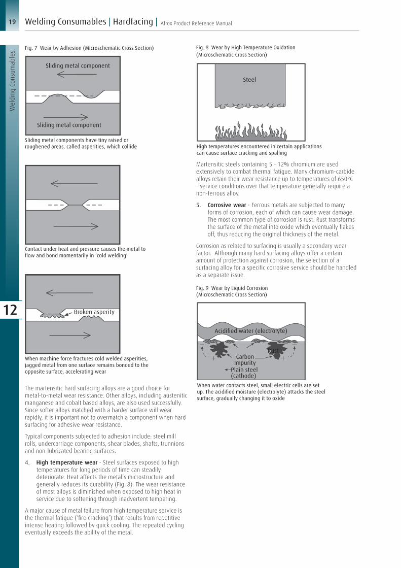
Fig. 7 Wear by Adhesion (Microschematic Cross Section)
Sliding metal component
Sliding metal component
Sliding metal components have tiny raised or roughened areas, called asperities, which collide
Contact under heat and pressure causes the metal to flow and bond momentarily in ‘cold welding’
Broken asperity
When machine force fractures cold welded asperities, jagged metal from one surface remains bonded to the opposite surface, accelerating wear
The martensitic hard surfacing alloys are a good choice for metal-to-metal wear resistance. Other alloys, including austenitic manganese and cobalt based alloys, are also used successfully. Since softer alloys matched with a harder surface will wear rapidly, it is important not to overmatch a component when hard surfacing for adhesive wear resistance.
Typical components subjected to adhesion include: steel mill rolls, undercarriage components, shear blades, shafts, trunnions and non-lubricated bearing surfaces.
4. High temperature wear - Steel surfaces exposed to high temperatures for long periods of time can steadily deteriorate. Heat affects the metal’s microstructure and generally reduces its durability (Fig. 8). The wear resistance of most alloys is diminished when exposed to high heat in service due to softening through inadvertent tempering.
A major cause of metal failure from high temperature service is the thermal fatigue (‘fire cracking’) that results from repetitive intense heating followed by quick cooling. The repeated cycling eventually exceeds the ability of the metal.
Fig. 8 Wear by High Temperature Oxidation (Microschematic Cross Section)
Martensitic steels containing 5 - 12% chromium are used extensively to combat thermal fatigue. Many chromium-carbide alloys retain their wear resistance up to temperatures of 650°C - service conditions over that temperature generally require a non-ferrous alloy.
5. Corrosive wear - Ferrous metals are subjected to many forms of corrosion, each of which can cause wear damage. The most common type of corrosion is rust. Rust transforms the surface of the metal into oxide which eventually flakes off, thus reducing the original thickness of the metal.
Corrosion as related to surfacing is usually a secondary wear factor. Although many hard surfacing alloys offer a certain amount of protection against corrosion, the selection of a surfacing alloy for a specific corrosive service should be handled as a separate issue.
Fig. 9 Wear by Liquid Corrosion (Microschematic Cross Section)
High temperatures encountered in certain applications can cause surface cracking and spalling
Steel
When water contacts steel, small electric cells are set up. The acidified moisture (electrolyte) attacks the steel surface, gradually changing it to oxide
CarbonImpurity
Acidified water (electrolyte)
Rust
Plain steel(cathode)

20Afrox Product Reference Manual
Wel
ding
Con
sum
able
s
| Welding Consumables | Hardfacing
12
Hard Surfacing Alloy ClassificationsAfrox supplies products for hard surfacing in both the iron-base and non-ferrous categories. The iron-base alloys represent by far the largest usage of the hard surfacing alloys and will be discussed in more detail. Iron-base hard surfacing alloys can be subdivided according to their metallurgical phase or microstructure, each type resisting certain forms of wear better and/or more economically than others. For simplification, Afrox groups the different classifications into three main alloy families:
a. Austenitic alloys
b. Martensitic alloys
c. Carbide alloys
Included in each family are products which combine properties of the main alloy family with properties common to another alloy family. These products were developed either to resist two kinds of wear simultaneously or incorporate certain desirable characteristics.
Austenitic hard surfacing alloys:
Excellent impact resistance
Fair abrasion resistance
Good build-up alloy.
Alloys which retain an austenitic microstructure at room temperature are referred to as austenitic. With compositions of 0,5 to over 1% carbon and from about 13 - 20% alloy (mainly manganese, with a few percent of nickel and/or chromium) they are commonly referred to as ‘austenitic manganese’ or ‘Hadfield manganese’ steels, similar to their base metal counterparts. These alloys are designed to match (or exceed) the properties of Hadfield manganese base metals. They are used extensively for rebuilding as a finished surface and prior to overlay of carbide alloys on austenitic manganese steel base metals.
Photomicrograph of austenite
Austenitic alloys with up to about 0,7% carbon and 20 - 30% alloy (usually about equal parts of manganese and chrome with some nickel) provide stable austenite even in high dilution situations on carbon and low alloy steels. This makes them a much better choice than the austenitic manganese alloys for overlay on carbon and low alloy steels or for dissimilar joining of manganese to carbon or low alloy steels.
Well designed austenitic surfacing alloys are extremely tough, ductile and work-hardenable. They offer excellent impact resistance, fair abrasion resistance (which improves as it work hardens) and have no relief checks. These alloys will normally work harden to a surface hardness up to 50 HRc and although this improves their abrasion resistance, they still retain their good impact resistance. The austenitic surfacing deposits, like
the austenitic manganese base metals (see Base Materials), should not be exposed for extended periods to temperatures over 260°C to minimise embrittlement.
Martensitic hard surfacing alloys:
Good impact resistance
Fair abrasion resistance
Good metal-to-metal wear resistance
Used both for build-up and overlay.
Martensite is a hard microstructural phase which is formed in steels by rapid cooling. Since martensitic alloys are air-hardenable, the cooling rate plays an important part in the final hardness; faster cooling usually results in harder surfacing deposits. Preheats of 121 - 316°C are generally required when working with martensitic alloys to avoid cracking in the weld deposit (base metal must also be taken into account).
Low carbon, low alloy (less than 5%) martensitic alloys are used primarily for build-up on carbon and low alloy steels. Their relatively high compressive strength, toughness and good metal-to-metal sliding wear resistance make them suitable for not only rebuilding components to their original dimensions, but as a substrate for harder surfacing materials.
Photomicrograph of martensite
Slightly higher carbon and higher alloy (6 - 12%) martensitic alloys exhibit significantly higher as-welded hardnesses. This hardness gives them better metal-to-metal and abrasive wear resistance than the build-up alloys, but lower toughness. Even though their toughness can be improved by tempering, they are primarily used as overlay alloys.
Another group of martensitic alloys common to hard surfacing are the martensitic stainless steels. Containing up to about 0,25% carbon and 18% alloy (mainly chromium), this group of alloys exhibits excellent thermal shock resistance. They also offer good metal-to-metal wear resistance and moderate corrosion resistance. They require rigid welding procedures for successful application and are used extensively for steel mill roll (including continuous caster) overlay.
Martensitic hard surfacing alloys provide a good balance of impact and abrasion resistance. By choosing the proper carbon-chromium content, it’s possible to choose the best compromise of abrasion, adhesion and impact resistance. The ability of martensitic alloys to respond to heat treatment also makes it possible to change their hardness/toughness after welding to better suit the service conditions. This alloy family should not be used for joining applications and should not be applied to austenitic base metals.
Carbide hard surfacing alloys

21 Afrox Product Reference Manual
Wel
ding
Con
sum
able
s
Welding Consumables | Hardfacing |
12
Excellent abrasion resistance
Good heat resistance
Fair corrosion resistance
Fair to low impact resistance.
By alloying several percent of carbon with a minimum 12% alloy (primarily chromium), hard carbides are formed and dispersed throughout the surfacing deposit (see Fig. 10). These dispersed carbides are much harder than the surrounding matrix and provide excellent abrasion resistance. They are used when the primary wear factor is abrasion.
At the lower end of the carbon range (less than 3%), the quantity of carbides is small compared to the matrix in which they’re dispersed and these alloys exhibit good abrasive wear resistance while retaining good toughness. These carbide surfacing alloys are used to resist a combination of abrasion and impact.
Photomicrograph of large carbides in a carbide eutectic matrix
As the carbon content increases (to as much as 7%) in the carbide containing alloys, the abrasion resistance increases and the toughness decreases (due to the higher percentage of carbides). All carbide surfacing develops transverse stress-relieving ‘check cracks’. The higher carbon alloys develop these cracks more readily and closer together than the lower carbon versions.
Fig. 10
As carbides are undermined and knocked out by moving abrasive particles, additional carbides are uncovered to further resist abrasives and delay wear
Steel base
These alloys should not be used for joining but can be applied to carbon steel, low alloy steel, austenitic manganese steel and cast iron (with special welding procedures). A sound, tough base material is preferred as a base for carbide surfacing alloys and the thickness of deposit is usually limited to 2 - 4 layers to prevent spalling. Care should be taken in applying carbide alloys to thin base metals since the stress relief cracks can propagate through thin sections. These alloys exhibit good abrasion
resistance at high temperatures (some up to 650ºC) and should be considered non-machinable.
Hard Surfacing MisconceptionGreater hardness does not always mean greater abrasion resistance or longer wear life. Several alloys may have the same hardness rating but vary greatly in their ability to withstand abrasive wear.
For example, many of the best Afrox surfacing alloys derive their high abrasion resistance from very hard carbides dispersed throughout a softer, tougher matrix. Bulk hardness tests (Rockwell or Brinell) which measure the average hardness of both the carbide and matrix together over a relatively large area, often register the same hardness as that of other conventional metals. But in actual performance, a carbide-containing surfacing alloy has substantially better abrasive wear resistance, as indicated in the graph (Fig. 11).
Similarly, when comparing several surfacing alloys with each other (Fig. 12), equally high bulk hardness ratings is not the only factor assuring resistance to wear. Resistance (especially to low- and high-stress abrasion) depends rather on a combination of both hardness and the metallurgical microstructure of the alloy. The microstructure of alloys varies according to the ratio of carbides to matrix and the type of carbides in the alloy. The alloy with the hardest, most evenly dispersed carbides along with the highest percentage of carbides will have the best resistance to low-stress and high-stress abrasion.
RELA
TIVE
LO
W-S
TRES
S SC
RATC
HIN
G RE
SIST
ANCE
AGA
INST
104
5 ST
EEL
1
2
3
4
6
8
10
20
(a)
10
45 S
teel
Cas
ting
(Rc
7)
(b)
0,9
% C
T
ool S
teel
Cas
ting,
Mar
tens
itic
(Rc
56)
(c)
Ni-
Har
d Ca
stin
g M
arte
nsiti
c
NI-
Cr Ir
on (
Rc 5
6)These test results show the last three metals sharing a Rockwell hardness value that is almost identical, yet their resistance to scratching abrasion differs greatly:• 1045 steel is used as the basis for comparison• Tool steel is only 1 and 3/4 times more abrasion resistant than 1045 steel• Ni-Hard metal is 8 times more resistant than 1045 steel• Composite surfacing is over 20 times more resistant than 1045 steel.
Hardness Compared to Wear Resistance Fig. 11
(d)
Com
posi
te S
urfa
cing
, Aus
teni
tic C
r Iro
n (R
c 55
)

22Afrox Product Reference Manual
Wel
ding
Con
sum
able
s
| Welding Consumables | Hardfacing
12
Afrox hard surfacing alloys fall not only into the alloy classifications, but also into two groups based on their primary usage:
1. Build-up alloys
2. Overlay alloys
Build-up alloys have good resistance to impact wear but only moderate resistance to abrasive wear. Such alloys may be used as wear surfaces themselves but more frequently they are employed as a base for a harder, abrasion resistant overlay. Both austenitic manganese and low alloy martensitic alloys are used for build-up.
Overlay alloys are hard overlays that have excellent abrasion resistance and fair to poor impact resistance. Due to their hardness, these alloys are usually limited to a specific number of layers. Certain martensitic alloys and all of the carbide alloys are used for overlay.
Comparison of Hard Surfacing Deposits: Hardness vs. Abrasion Resistance
Tube-Alloy 258-0 - MartensiticAverage deposit hardness - 58 HRc
Tube-Alloy 258 Tic-0 - Titanium CarbideAverage deposit hardness - 58 HRc
Tube-Alloy 255-0 - Chrome CarbideAverage deposit hardness - 55 HRc
Better abrasion resistance than carbon steel, abrasive particle still scratches slivers out of surface
Even greater abrasion resistance since abrasive particle scratches out less matrix before hitting small titanium carbides
Superior abrasion resistance since abrasive particle scratches out very little matrix before hitting large, plentiful chrome carbides
Steel base Steel base Steel base
Compositesurfacing
Compositesurfacing
Compositesurfacing
Long sliver Shorter sliver
Titaniumcarbide
Matrix
Minimal sliver
Chromiumcarbide
Matrix
Fig. 12

23 Afrox Product Reference Manual
Wel
ding
Con
sum
able
s
Welding Consumables | Hardfacing |
12
Identification of MetalsThe ability to recognise different types of metals is of considerable importance in welding and/or hardfacing. Different metals often require different welding techniques and in some cases careful selection of hardfacing products.
In many cases, a metal can be identified by machine drawings or specifications. There will, however, be a number of occasions when there will be a reasonable doubt as to what metal a certain item is made from. The following is a guide to the identification of most common metals and should prove adequate for most welding purposes.
File Test
It is often possible to distinguish mild steel and wrought iron (which are welded in the same manner) from other steels by filing, using a known piece of mild steel for comparison purposes.
Holding the unknown piece of steel firmly, in a vice if required, take one firm cut at it using the corner of a large file. The file should only be pushed in the forward direction while in contact with the metal. Do a similar cut, using similar speed and pressure on the known piece of mild steel.
If they behave in a similar manner, that is, they both cut to similar depths and if the file feels to have the same amount of ‘drag’, etc., it is very likely that the unknown piece is either mild steel or wrought iron and can be welded as such.
If they do not behave in a similar manner, it is almost definite that the piece is either high carbon or alloy steel. It is possible to differentiate between these two using a spark test.
Spark Test
Different types of steels will react differently when held against the wheel of a power grinder. For distinguishing between different types of steels by this technique, it is advisable to have some pieces of known types to use as comparisons.
The piece of steel is held firmly against the rotating wheel in such a manner that the sparks can be observed as they leave the wheel. The appearance of the spark pattern is then compared with those shown in Fig. 13 and if possible, with those obtained from pieces of steel of known types. It is important when comparing pieces of steel by spark test that the same pressure is used to hold the specimen against the wheel in each case.
Identification of Common Metals
Metal Appearance of the metal surface in its common rough condition
Appearance of freshly filed metal
Appearance of fractures and relative toughness of metal
Further test required to identify type
Grey cast iron Dark grey or rusty, rough, sandy surface
Light grey, fairly smooth
Dark grey, rough granular surface. Very brittle
Chisel test
White cast iron As above Generally too hard to file. Shiny white when ground
Medium grey colour. Very tough to quite brittle depending on type and condition
Nil
Mild steel, wrought iron, cast steel, alloy steels, high carbon steel, 11-14% manganese steel
Dark grey or rusty. Can be smooth or rough depending on application
Bright grey, very smooth surface. Some alloy steels are too hard to file
Fine grey surface may be tough to quite brittle
File testSpark testMagnet testChisel test
Stainless steel Bright silvery grey if polished. Rough dull grey if not polished
Bright silvery grey. Smooth surface. Some are too hard to file
Useful Hardfacing Data
Back to contents

24Afrox Product Reference Manual
Wel
ding
Con
sum
able
s
| Welding Consumables | Hardfacing
12
Magnet Test
It is possible to distinguish between austenitic steels and the ferritic and martensitic types by their magnetic properties.
Many items subject to impact such as crusher jaws, impact bars, swing hammers, etc. are made from 11 - 14% manganese steels. These appear in many respects to be similar to mild steel or low alloy steels and are difficult to distinguish by normal visual inspection, file tests and spark tests. Their main feature is that they will not be attracted by a magnet. Hence, any doubtful steels should be checked with a magnet and, if they are not strongly attracted, treated as manganese steels.
Stainless steels also can be magnetic or non-magnetic. Always check with a magnet prior to welding. If non-magnetic (no attraction), they are the austenitic type. If they are magnetic, they are either ferritic or martensitic and should be treated as such.
Chisel Test
It is often difficult to determine whether a machine component is cast iron or cast steel simply by appearance. One of the most reliable tests is to try and remove a small piece with a sharp cold chisel.
Cast iron will come away in distinct chips when the chisel is hit with a hammer. Cast steel, on the other hand, is more ductile and will peel away in slivers.
Wrought Iron Mild SteelCast Steel
White Cast Iron Grey Cast Iron
Colour - straw yellowAverage stream with power grinder - 165 cm Volume - largeLong shafts ending in forks and arrow-like appendages Colour - white
Colour - whiteAverage length of stream with power grinder - 178 cmVolume - moderately largeShafts shorter than wrought iron and in forks and appendages.Forks become more numerous and sprigs appear as carbon content increases
Colour - redColour - straw yellowAverage stream length with power grinder - 50 cmVolume - very smallSprigs - finer than grey iron, small and repeating
Colour - redColour - straw yellowAverage stream length with power grinder - 63 cmVolume - smallMany sprigs, small and repeating
High Carbon Steel Stainless SteelAlloy Steel
Malleable Iron Nickel & Monel
Colour - whiteAverage stream length with power grinder - 140 cmVolume - large Numerous small and repeating sprigs
Colour - straw yellowStream length varies with types and amount of alloy content Colour - white Shafts may end in forks, buds or arrows, frequently with break between shaft and arrow
Colour - straw yellowAverage stream length with power grinder - 76 cmVolume - moderate Longer shafts than grey iron ending in numerous small, repeating sprigs
Colour - orange Average stream length with power grinder - 25 cm Short shafts with no forks or sprigs
Fig. 13

25 Afrox Product Reference Manual
Wel
ding
Con
sum
able
s
Welding Consumables | Hardfacing |
12
Afrox Covered Surfacing ElectrodesIn general, Afrox electrodes have excellent operating characteristics in the flat position; vertical surfaces may be overlayed by building a series of horizontal beads on a ‘shelf’. As with most welding electrodes, the smaller sizes have better operating characteristics when welding vertical surfaces. For maximum deposition rates, use higher amperages and a wide weave technique. For most Afrox electrodes, weaving up to four electrode diameters is satisfactory. To minimise penetration and thus weld metal dilution, use lower amperages. Holding a longer arc (higher voltage) will produce a wider, flatter bead and will increase heat input into the base metal. When welding on manganese steel castings, currents as low as possible should be used to prevent overheating of the base metal. The surface to be built up should be ground to remove the work hardened area, cracked or spalled metal, and any other foreign material. Peening is recommended on heavy build-ups.
Afrox Flux Cored Open Arc Surfacing Wires
Afrox Metal Cored Submerged Arc and Gas Assisted Cored Surfacing Wires
Submerged Arc Welding of Cylindrical Components
Afrox open arc wires require no external shielding gas and have a steady arc with globular transfer. Spatter and noise levels are minimal, with complete slag coverage, which removes easily. Increasing amperage will increase deposition rate, penetration (higher base metal dilution) and heat input into the base metal. Increasing voltage will widen and flatten the weld bead. Excessive voltage will result in porosity. Control of wire extension (stick out) is important with excessively short stick out resulting in scattered internal porosity and excessively long stick out resulting in increased spatter. Afrox open arc wires can be used with either a variable or a constant voltage power source with the latter preferred. Constant and variable speed wire feeders are both being used successfully with the proper power source.
General Advantages of Afrox 1,2 mm and 1,6 mm Wires
1. Permits marked reduction in welding costs (as much as 2/3 cost saving) - deposition rate greater than that of manual electrode or gas shielded wires.
2. Simplicity of operation with lightweight guns and no gas lines.
3. With proper procedures, can be used to surface in the vertical position.
4. More adaptable on small thin parts and edges - holds corners.
It must be emphasised that 1,2 mm and 1,6 mm Afrox wires are not all-positional wires in the true sense of the word. They can be used to weld vertical surfaces with a horizontal stringer technique. A shelf may be required on the initial pass and amperages in the lower end of the range (approx. 200 A), fast travel speed and a nozzle angle inclined up 15º should be used.
For cylindrical submerged arc welding, the factors which control bead contour are: 1) arc voltage 2) amperage 3) rotation speed and 4) lead.
Arc Voltage. Arc voltage should be preset at approximately 26 - 30 V. A decrease in arc voltage will shorten the arc and tend to produce a higher, narrower bead. If the voltage is increased, the arc will become longer, penetration will be deeper and additional dilution with the base metal will result.
Amperage. The rate of wire burn-off and heat input are functions of the welding current. With 3,2 mm wire, a good starting point is 425 A, 4,0 mm 500 A. More metal will be deposited with higher amperages but higher heat input will result. As heat builds up, especially in parts of small diameter, the contour of the bead is more difficult to control.
Rotating Surface Speed. A good starting point is approximately 400 mm/min. If the surface speed in increased, a narrower bead will result. When decreased, a wider bead is deposited.
Lead. After the above three parameters have been set, the contour of the bead can be controlled by varying the amount of lead. Lead is the distance ahead of dead centre. Position the electrode ahead of dead centre sufficiently so the molten pool solidifies as it passes top dead centre.
Diameter mm ahead of dead centre
75 - 450 20 - 25
450 - 1 000 25 - 38
On small diameters, the correct lead is particularly important since the molten slag tends to run before freezing. When insufficient lead is used, the bead will be convex and undercut the edges. When too much lead is used, the bead will be flat or concave and tend to have centreline cracks. The correct lead produces a bead having a slight crown and long lines of solidification.
WELDING PROCEDURES FOR SURFACING ELECTRODES AND WIRES
Corewear Flux Cored Open Arc Wires General Operating Parameters 2,0 mm dia 2,4 mm dia 2,8 mm dia Use 40 - 50 mm stick out Use 50 - 60 mm stick out Use 50 - 60 mm stick out DC reverse polarity DC reverse polarity DC reverse polarity
A V A V A V 200 - 400 25 - 35 280 - 340 28 - 29 350 - 400 28 - 29
Tube Alloy Flux Cored WiresGeneral Operating Parameters
1,2 mm dia 1,6 mm dia 2,0 mm dia 2,8 mm dia Use 12 - 25 mm stick out DC Use 25 - 38 mm stick out DC Use 25 - 38 mm stick out DC Use 38 - 50 mm stick out DC reverse polarity reverse polarity reverse polarity reverse polarity
A V A V A V A V 120 - 160 19 - 23 225 - 275 23 - 25 275 - 350 26 - 28 350 - 400 24 - 27 160 - 190 24 - 25 275 - 350 24 - 27 350 - 400 27 - 29 400 - 450 26 - 29 190 - 230 26 - 27 350 - 400 26 - 29 450 - 475 28 - 32 450 - 500 28 - 32
Tube Alloy Metal Cored Submerged Arc Wires General Operating Parameters
2,4 mm dia 3,2 mm dia 4,0 mm dia Use 25 - 32 mm stick out, Use 32 - 38 mm stick out, Use 32 - 38 mm stick out, travel speed of 305 - 406 mm/min travel speed of 356 - 456 mm/min travel speed of 406 - 508 mm/min
A V A V A V 350 - 400 25 - 26 400 - 450 26 - 28 450 - 500 28 - 30 400 - 450 26 - 27 450 - 500 27 - 30 500 - 600 29 - 32 450 - 500 28 - 29 500 - 550 29 - 32
Corewear Flux Cored Gas Assisted Wires General Operating Parameters 1,2 mm dia 1,6 mm dia 2,0 mm dia Use CO2 gas 15-25 l/m Use CO2 gas 15 - 25 l/m Use CO2 gas 15 - 25 l/m DC reverse polarity DC reverse polarity DC reverse polarity
A V A V A V 150 - 300 25 - 35 200 - 400 25 - 35 300 - 500 23 - 35

26Afrox Product Reference Manual
Wel
ding
Con
sum
able
s
| Welding Consumables | Hardfacing
12
DIN 8555 SPECIFICATION FOR HARDFACING CONSUMABLES
XXX XX - XX - XXX - XXXX
Welding Process
Alloy Group Method ofProduction
HardnessLevel
HardnessRange
Weld Metal Properties
G - Gas Welding
1 Unalloyed < 0,4% C or low alloyed< 0,4% C and < 5,0% Cr, Ni, Mo, Mn
GW - Rolled 150 125 - 175 HB C Corrosion resistant
E - MMA 2 Unalloyed < 0,4% C or low alloyed< 0,4% C and < 5,0% Cr, Ni, Mo, Mn
GO - Cast 200 175 - 225 HB G Resists abrasive wear
MF - FCAW 3 Alloyed with properties of hotworked steel
GZ - Drawn 250 225 - 275 HB K Work hardens
TIG - TIG 4 Alloyed with properties of hotworked steel
GS - Sintered 300 275 - 325 HB N Non-magnetic
MSG - MIG 5 Alloyed with> 5,0% Cr with low Cup to 0,2%
GF - Cored 35 325 - 375 HB P Impact resistant
UP - SAW 6 Alloyed with > 5,0% Cr with C from 0,2 - 2,0%
UM - Covered 400 375 - 450 HB R Rust resistant
7 Mn austenites with 11 - 18% Mn and up to 3% Ni
40 37 - 42 HRc S Cutting ability HSS
8 CrNiMn austenites 45 42 - 47 HRc T High temp strength
9 CrNi steel resistant to rust, acid and heat
50 47 - 52 HRc Z Heat resistant above 600ºC
10 High C, high Cr without othercarbide formers
55 52 - 57 HRc
20 Co based, CrW alloyed with orwithout Ni or Mo
60 57 - 62 HRc
21 Carbide based sintered cast or cored 65 62 - 67 HRc
22 Ni based Cr alloyed CrB alloyed 70 67+ HRc
23 Ni based Mo alloyed with orwithout Cr
30 Cu based Sn alloyed
31 Cu based AI alloyed
31 Cu based Ni alloyed
MSG 10 - GF - 60 - G Rust resistant
Is a MIG wire with Hi C%, Hi Cr% without other carbide formers, it is a cored wire having a hardness in the range of 57 - 62 HRc and is resistant to abrasion
MSG 1 0-GF-60-GExample

27 Afrox Product Reference Manual
Wel
ding
Con
sum
able
s
Welding Consumables | Hardfacing |
12
Afrox 300 is a basic coated, AC/DC all-position electrode depositing a tough chromium alloy weld metal with a hardness of 250 - 300 HV (up to 30 HRc). The weld metal may be hardened to above 480 HV (48 HRc) by heating to 900°C and quenching in oil. The weld deposit is capable of withstanding moderate rolling loads, mild abrasion and frictional loading with good resistance to impact.
Applications
Afrox 300 is suitable for rebuilding worn steel or low alloy machine parts, which require machining after welding. It can also be used as a buffer layer between base material and harder overlays. Typical components to be welded with this electrode include shafts, mine car wheels, track links, dragline chains, worn rail ends, tractor rails, drive sprockets, etc. Afrox 300 may be multi-layered.
Typical Chemical Analysis (All weld metal)
% Carbon 0,05 - 0,1 % Chromium 3,0 - 3,5
% Manganese 0,35 - 0,9 % Molybdenum 0,1 max
% Silicon 0,7 max
Classifications
DIN 8555 E1-UM-300-P
AWS A5.13:2000 EFe1 (nearest)
EN 14700:2005 EFe1 (nearest)
Typical Hardness
HRc 26 - 31
Packing Data(DC+ AC 70 OCV min)
Diameter (mm)
Electrode Length(mm)
Current (A)
Pack Mass (kg)
Item Number
3,15 350 110 - 145 4,0 W075603
4,0 350 140 - 180 4,0 W075604
5,0 450 180 - 240 6,0 W075605
Afrox 300
Hardfacing Electrodes
Back to contents

28Afrox Product Reference Manual
Wel
ding
Con
sum
able
s
| Welding Consumables | Hardfacing
12
Afrox 350
Afrox 350 is a basic coated, all-position electrode depositing a tough chromium alloy weld metal. The weld metal is capable of withstanding high impact and rolling loads with good resistance to mild abrasive wear.
Applications
Afrox 350 is suitable for welding rail ends and railway lines and various other applications where moderate hardness and machinability is required.
Typical Chemical Analysis (All weld metal)
% Carbon 0,06 - 0,08 % Silicon 0,4 - 0,6
% Manganese 0,6 - 0,9 % Chromium 3,2 - 4,9
Classifications
DIN 8555 E1-UM-350-P
AWS A5.13:2000 EFe1 (nearest)
EN 14700:2005 EFe1 (nearest)
Typical Hardness
HRc 32 - 40
Packing Data(AC DC+ 70 OCV min)
Diameter (mm)
Electrode Length(mm)
Current (A)
Pack Mass (kg)
Item Number
5,0 450 170 - 250 6,0 W075609

29 Afrox Product Reference Manual
Wel
ding
Con
sum
able
s
Welding Consumables | Hardfacing |
12
Afrox 400
Afrox 400 is a rutile coated, AC/DC electrode depositing a tough chromium manganese alloy weld metal with a hardness of 320 - 400 HV (32-40 HRc). The weld deposit is hard enough to resist serious deformation under fairly heavy impact and rolling loads, yet has good resistance to mild abrasive wear. The electrode has a smooth soft arc with low spatter volume and can be used in all positions.
Applications
Afrox 400 is suitable for metal-to-metal wear applications involving abrasion and/or impact loads. The electrode is recommended for applications where maximum hardness consistent with reasonable machinability is required (machinable with carbide-tipped tools only). Typical applications include tractor idlers, track rolls, dragline pins, drive sprockets and gears, cable sheaves, hot metal or slag ladle pins, etc. The low open circuit voltage allows this electrode to be used on small AC machines.
Typical Chemical Analysis (All weld metal)
% Carbon 0,1 - 0,2 % Chromium 2,4 - 4,0
% Manganese 0,3 - 1,0 % Molybdenum 0,1 max
% Silicon 0,5 - 1,0
Classifications
DIN 8555 E1-UM-350-P
AWS A5.13:2000 EFe1 (nearest)
EN 14700:2005 EFe1 (nearest)
Typical Hardness
HRc 37 - 47
Packing Data(AC DC- 50 OCV min)
Diameter (mm)
Electrode Length(mm)
Current (A)
Pack Mass (kg)
Item Number
4,0 350 120 - 160 5,0 W075634

30Afrox Product Reference Manual
Wel
ding
Con
sum
able
s
| Welding Consumables | Hardfacing
12
Afrox 452
Afrox 452 is a basic coated AC/DC all-position electrode depositing a weld containing chromium, nickel and molybdenum. The weld metal, which comprises metallic carbides in a martensitic matrix, has a hardness of 420 - 480 HV (43 - 48 HRc). The weld metal provides good resistance to abrasion and impact under rolling and to impact loads in wet and dry conditions.
Applications
This versatile electrode is suitable for use in applications where frictional loads and metal-to-metal wear conditions occur. The weld metal is extremely resistant to breakout or spalling, which makes it eminently suitable to use on permanent way crossings, rail ends, excavator bucket lips, tractor drive sprockets and track links, crane drive wheels, etc. The deposit, which is machinable with carbide-tipped tools, is also suitable for use as a low cost buffer layer for the deposition of high alloy wear resistant deposits.
Typical Chemical Analysis (All weld metal)
% Carbon 0,17 - 0,25 % Chromium 2,0 - 3,0
% Manganese 0,9 - 1,4 % Nickel 1,6 - 2,2
% Silicon 0,2 - 0,4 % Molybdenum 0,65 - 0,95
Classifications
DIN 8555 E1-UM-45-GP
AWS A5.13:2000 EFe2 (nearest)
EN 14700:2005 EFe3 (nearest)
Typical Hardness
HRc 43 - 48
Packing Data(AC DC+ 70 OCV min)
Diameter (mm)
Electrode Length(mm)
Current (A)
Pack Mass (kg)
Item Number
4,0 350 110 - 170 5,0 W075674
5,0 450 170 - 270 6,0 W075675

31 Afrox Product Reference Manual
Wel
ding
Con
sum
able
s
Welding Consumables | Hardfacing |
12
Afrox 600
Afrox 600 is a basic coated AC/DC electrode depositing a martensitic weld metal having a hardness of approximately 470 - 700 HV (47 - 60 HRc). The weld metal has good resistance to fine mineral abrasion with moderate resistance to impact.
Applications
Afrox 600 has been designed for application involving metal to mineral conditions such as those experienced by earth moving equipment working in sandy conditions. Typical uses are grader blades, earth scoops, bucket lips, grousers, conveyor screws, blast hole augers, etc.
Typical Chemical Analysis (All weld metal)
% Carbon 0,45 - 0,6 % Chromium 5,0 - 8,0
% Manganese 0,3 - 1,1 % Molybdenum 0,3 - 0,6
% Silicon 0,4 - 1,3
Classifications
DIN 8555 E4-UM-55-G
AWS A5.13:2000 EFe3 (nearest)
EN 14700:2005 EFe2 (nearest)
Typical Hardness
HRc 47 - 60
Packing Data(AC DC+ 70 OCV min)
Diameter (mm)
Electrode Length(mm)
Current (A)
Pack Mass (kg)
Item Number
3,15 350 110 - 145 4,0 W075613
4,0 450 140 - 180 6,0 W075614
5,0 450 180 - 240 6,0 W075615

32Afrox Product Reference Manual
Wel
ding
Con
sum
able
s
| Welding Consumables | Hardfacing
12
Afrox 650A
Afrox 650A is a basic coated AC/DC all-position electrode depositing a weld metal containing chromium, molybdenum and vanadium. The weld metal which has an approximate hardness of 550 - 650 HV (53 - 58 HRc) is grindable only and has good resistance to abrasion with moderate to high impact resistance. Due to its high alloy content, the deposited weld metal has excellent hardness to 500°C.
Applications
Afrox 650A deposits a martensitic steel weld metal which is suitable for use on a wide variety of tool and metal-to-metal applications such as guillotine blades, punches, dies, pneumatic drills, chisels, axes, ripper teeth and wood chipper anvils.
Typical Chemical Analysis (All weld metal)
% Carbon 0,45 - 0,65 % Chromium 5,5 - 7,5
% Manganese 0,5 - 1,25 % Molybdenum 4,5 - 6,5
% Silicon 0,1 - 0,5 % Vanadium 0,5 - 0,1
Classifications
DIN 8555 E6-UM-55-GS
AWS A5.13:2000 EFe3 (nearest)
EN 14700:2005 EFe3 (nearest)
Typical Hardness
HRc 53 - 58
Packing Data(AC DC+ 70 OCV min)
Diameter (mm)
Electrode Length(mm)
Current (A)
Pack Mass (kg)
Item Number
3,15 350 80 - 120 4,0 W075623
4,0 350 120 - 160 4,0 W075624

33 Afrox Product Reference Manual
Wel
ding
Con
sum
able
s
Welding Consumables | Hardfacing |
12
Afrox CrMn
Afrox CrMn is a rutile coated electrode designed for joining and surfacing 11 - 14% manganese steels. The deposited weld metal will work harden under impact load to a hardness of 480 - 590 HV. The electrode is recommended for use in the downhand position only.
Applications
Afrox CrMn can be used to reclaim worn austenitic manganese parts or as a buffer layer on other grades of steels prior to hardfacing. The deposit is extremely crack resistant and will rapidly work harden, making it ideally suited for welding on railway crossings, dredger buckets, crusher jaws, loader buckets and other ground engaging equipment.
Typical Chemical Analysis (All weld metal)
% Carbon 0,5 - 0,9 % Silicon 0,1 - 0,5
% Manganese 15,0 - 18,0 % Chromium 12,0 - 15,0
Classifications
DIN 8555 E8-UM-200/55-KP
AWS A5.13:2000 EFe MnCr (nearest)
EN 14700:2005 EFe9 (nearest)
Packing Data(AC DC+ 70 OCV min)
Diameter (mm)
Electrode Length(mm)
Current (A)
Pack Mass (kg)
Item Number
4,0 350 130 - 170 4,0 W075628
5,0 350 170 - 220 4,0 W075629
Typical Hardness
As Deposited 22 HRc
Work Hardened 48 - 55 HRc

34Afrox Product Reference Manual
Wel
ding
Con
sum
able
s
| Welding Consumables | Hardfacing
12
Afrox NiMn
Afrox NiMn is a basic coated electrode designed to provide a non-magnetic austenitic 11 - 14% manganese deposit for service involving high impact. The deposits are extremely tough, non-porous, crack-free and work hardened readily under impact loading to approximately 440 - 600 HV (45 - 55 HRc). The electrode is recommended for downhand welding only.
Applications
Although primarily intended for reclaiming worn parts made from 11 - 14% manganese steel (Hadfield manganese steel), Afrox NiMn can also be used for joining this material or hardfacing carbon steel components subject to severe impact loads. Under these conditions, an austenitic stainless steel buffer layer should be applied. This electrode can be used on cast manganese steel railway crossings, dredger buckets, crusher jaws, swing hammers, blow bars and grizzlies.
Typical Chemical Analysis (All weld metal)
% Carbon 0,5 - 0,9 % Nickel 2,75 - 6,0
% Manganese 11,0 - 16,0 % Chromium 0,5 max
% Silicon 1,3 max
Classifications
DIN 8555 E6-UM-55-GS
AWS A5.13:2000 EFe Mn-A (nearest)
EN 14700:2005 EFe9 (nearest)
Typical Hardness
As Deposited 24 HRc
Work Hardened 45 - 55 HRc
Packing Data(DC+ 70 OCV min)
Diameter (mm)
Electrode Length (mm)
Current (A)
Pack Mass (kg)
Item Number
4,0 350 130 - 170 4,0 W075664
5,0 450 170 - 220 6,0 W075665
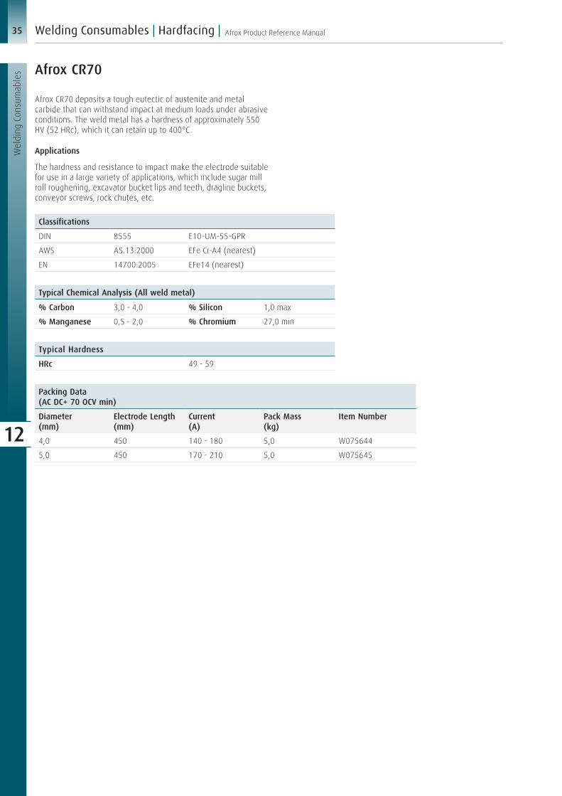
35 Afrox Product Reference Manual
Wel
ding
Con
sum
able
s
Welding Consumables | Hardfacing |
12
Afrox CR70
Afrox CR70 deposits a tough eutectic of austenite and metal carbide that can withstand impact at medium loads under abrasive conditions. The weld metal has a hardness of approximately 550 HV (52 HRc), which it can retain up to 400°C.
Applications
The hardness and resistance to impact make the electrode suitable for use in a large variety of applications, which include sugar mill roll roughening, excavator bucket lips and teeth, dragline buckets, conveyor screws, rock chutes, etc.
Typical Chemical Analysis (All weld metal)
% Carbon 3,0 - 4,0 % Silicon 1,0 max
% Manganese 0,5 - 2,0 % Chromium 27,0 min
Classifications
DIN 8555 E10-UM-55-GPR
AWS A5.13:2000 EFe Cr-A4 (nearest)
EN 14700:2005 EFe14 (nearest)
Typical Hardness
HRc 49 - 59
Packing Data(AC DC+ 70 OCV min)
Diameter(mm)
Electrode Length(mm)
Current (A)
Pack Mass (kg)
Item Number
4,0 450 140 - 180 5,0 W075644
5,0 450 170 - 210 5,0 W075645
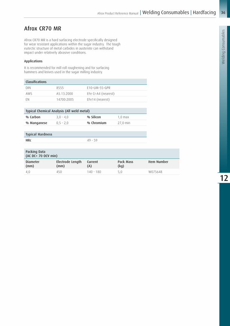
36Afrox Product Reference Manual
Wel
ding
Con
sum
able
s
| Welding Consumables | Hardfacing
12
Afrox CR70 MR
Afrox CR70 MR is a hard surfacing electrode specifically designed for wear resistant applications within the sugar industry. The tough eutectic structure of metal carbides in austenite can withstand impact under relatively abrasive conditions.
Applications
It is recommended for mill roll roughening and for surfacing hammers and knives used in the sugar milling industry.
Typical Chemical Analysis (All weld metal)
% Carbon 3,0 - 4,0 % Silicon 1,0 max
% Manganese 0,5 - 2,0 % Chromium 27,0 min
Classifications
DIN 8555 E10-UM-55-GPR
AWS A5.13:2000 EFe Cr-A4 (nearest)
EN 14700:2005 EFe14 (nearest)
Typical Hardness
HRc 49 - 59
Packing Data(AC DC+ 70 OCV min)
Diameter (mm)
Electrode Length(mm)
Current (A)
Pack Mass (kg)
Item Number
4,0 450 140 - 180 5,0 W075648

37 Afrox Product Reference Manual
Wel
ding
Con
sum
able
s
Welding Consumables | Hardfacing |
12
AZUCAR 80
AZUCAR 80 deposits a tough eutectic of austenite and metal carbide that can withstand impact at medium loads under abrasive conditions. The weld metal has a hardness of approximately 550 HV (52 HRc), which it can retain up to 400°C.
Applications
The hardness and resistance to impact make the electrode suitable for use in a large variety of applications, which include sugar mill roll roughening, excavator bucket lips and teeth, dragline buckets, conveyor screws, rock chutes, etc.
Typical Chemical Analysis (All weld metal)
% Carbon 3,0 - 4,0 % Silicon 1,0 max
% Manganese 0,5 - 2,0 % Chromium 27,0 min
Classifications
DIN 8555 E10-UM-55-GPR
AWS A5.13:2000 EFe Cr-A4 (nearest)
EN 14700:2005 EFe14 (nearest)
Typical Hardness
HRc 49 - 59
Packing Data(AC DC+ 70 OCV min)
Diameter(mm)
Electrode Length(mm)
Current (A)
Pack Mass (kg)
Item Number
3,15 350 110 - 160 5,0 W189653
4,0 450 140 - 180 5,0 W189654
5,0 450 170 - 210 5,0 W189655

38Afrox Product Reference Manual
Wel
ding
Con
sum
able
s
| Welding Consumables | Hardfacing
12
AZUCAR 100
AZUCAR 100 is a chromium carbide hardfacing electrode for use in the downhand position only. The weld metal is unmachinable, but can be ground. The deposited metal is highly resistant to abrasive wear with moderate impact and is recommended for general hardfacing applications on carbon steels, 14% manganese steels and cast iron. Deposits should be limited to two layers to eliminate relief checks.
Applications
The electrode is recommended for general hardfacing applications on carbon steel, alloy steel and cast iron parts. Typical components welded are dredger buckets, excavator shovels, dragline teeth, bulldozer cutting edges and agricultural implements.
Typical Chemical Analysis (All weld metal)
% Carbon 3,5 - 4,5 % Silicon 1,5 max
% Manganese 0,5 - 2,0 % Chromium 33,0 - 38,0
Classifications
DIN 8555 E10-UM-55-GPR
AWS A5.13:2000 EFe Cr-A8 (nearest)
EN 14700:2005 EFe14 (nearest)
Typical Hardness
Matrix 49 - 59 HRc
Carbides 1 500 HV
Packing Data(AC DC+/- 70 OCV min)
Diameter (mm)
Electrode Length(mm)
Current (A)
Pack Mass (kg)
Item Number
4,0 450 160 - 200 5,0 W189644

39 Afrox Product Reference Manual
Wel
ding
Con
sum
able
s
Welding Consumables | Hardfacing |
12
Afrox Cobalarc 1
Afrox Cobalarc 1 is a chromium carbide hardfacing electrode for use in the downhand position only. The weld metal is unmachinable, but can be ground. The deposited metal is highly resistant to abrasive wear with moderate impact and is recommended for general hardfacing applications on carbon steels, 14% manganese steels and cast iron. Deposits should be limited to two layers to eliminate relief checks.
Applications
The electrode is recommended for general hardfacing applications on carbon steel, alloy steel and cast iron parts. Typical components welded are dredger buckets, excavator shovels, dragline teeth, bulldozer cutting edges and agricultural implements.
Typical Chemical Analysis (All weld metal)
% Carbon 3,5 - 4,5 % Silicon 1,5 max
% Manganese 0,5 - 2,0 % Chromium 33,0 - 38,0
Classifications
DIN 8555 E10-UM-55-GPR
AWS A5.13:2000 EFe Cr-A8 (nearest)
EN 14700:2005 EFe14 (nearest)
Typical Hardness
Matrix 49 - 59 HRc
Carbides 1 500 HV
Packing Data(AC DC+/- 70 OCV min)
Diameter (mm)
Electrode Length(mm)
Current (A)
Pack Mass (kg)
Item Number
4,0 450 160 - 200 5,0 W075684
5,0 450 160 - 240 5,0 W075685

40Afrox Product Reference Manual
Wel
ding
Con
sum
able
s
| Welding Consumables | Hardfacing
12
Afrox Cobalarc 9
Afrox Cobalarc 9 is a complex carbide type hardfacing electrode containing molybdenum and vanadium. The deposited weld metal consists of primary carbide needles in a matrix of carbide/austenite eutectic. The material is highly resistant to abrasive wear with high-impact loading. The electrode is suitable for use in the downhand position only, deposits relief check and should be limited to two layers only.
Applications
Cobalarc 9 is suitable for use on railway tampers, sizing screens, dredger buckets and lips, augers, rolling mill guides and pump impellers.
Typical Chemical Analysis (All weld metal)
% Carbon 4,0 - 5,0 % Chromium 25,0 - 29,0
% Manganese 1,0 - 1,5 % Molybdenum 2,0 min
% Silicon 1,5 max % Vanadium 1,0 max
Classifications
DIN 8555 E10-UM-60-GP (nearest)
AWS A5.13:2000 EFe Cr-A7 (nearest)
EN 14700:2005 EFe14 (nearest)
Typical Hardness
Matrix 55 - 65 HRc
Carbides 1 500 HV
Packing Data(AC DC+/- 70 OCV min)
Diameter (mm)
Electrode Length(mm)
Current (A)
Pack Mass (kg)
Item Number
3,15 350 100 - 145 5,0 W075593
4,0 450 160 - 200 5,0 W075594
5,0 450 160 - 240 5,0 W075595

41 Afrox Product Reference Manual
Wel
ding
Con
sum
able
s
Welding Consumables | Hardfacing |
12
MIG 410/TIG 410
MIG/TIG 410 is a solid wire depositing a 410 stainless steel weld metal. It offers good resistance to fire cracking and corrosion frequently encountered in steel mill rolls and produces sound, porosity-free, crack-free weld deposits. A preheat of 200ºC is generally needed to provide crack-free welds.
Applications
MIG/TIG 410 can be used on hydrocrackers, reaction vessels, distillation plants, refineries, furnaces, lining, run-out rolls, valve bodies, turbine parts and burner nozzles.
Typical Chemical Analysis (All weld metal)
% Carbon 0,06 - 0,12 % Silicon 0,25 - 0,5
% Manganese 0,6 max % Chromium 12,0 - 13,5
Recommended shielding gas: Argoshield®, Stainshield® (MIG), Argon (TIG)
Packing Data TIG
Diameter (mm)
Tube Mass (kg)
Item Number
1,6 5,0 W077389
2,4 5,0 W077390
Packing Data MIG
Diameter (mm)
Spool Mass (kg)
Spool Type Item Number
1,2 15,0 Wire Basket W077375
1,6 15,0 Wire Basket W077376
Typical Hardness
HRc 25 - 35
Classifications
DIN 8555 MSG5-GZ-300-CG
Hardfacing Gas Assisted Wires
Back to contents

42Afrox Product Reference Manual
Wel
ding
Con
sum
able
s
| Welding Consumables | Hardfacing
12
MIG 410NiMo/TIG 410NiMo
MIG/TIG 410NiMo is a solid wire depositing a soft martensitic stainless steel weld metal. It offers good resistance to fire cracking and corrosion frequently encountered in steel mill rolls. It produces sound, porosity-free, crack-free weld deposits.
Applications
MIG/TIG 410NiMo can be used on hydraulic turbines, valve bodies, pump bowls, compressor cones, impellers, high pressure pipes, power generation, offshore oil, chemical and petrochemical plants.
Typical Chemical Analysis (All weld metal)
% Carbon 0,05 max % Chromium 11,0 - 12,5
% Manganese 0,4 - 1,0 % Nickel 4,0 - 5,0
% Silicon 0,6 max % Molybdenum 0,4 - 0,7
Classifications
DIN 8555 MSG5-GZ-300-CG
Typical Hardness
HRc 25 - 30
Recommended shielding gas: Argoshield®, Stainshield® (MIG), Argon (TIG)
Packing Data TIG
Diameter (mm)
Tube Mass (kg)
Item Number
1,6 5,0 W077396
2,4 5,0 W077397
Packing Data MIG
Diameter (mm)
Spool Mass (kg)
Spool Type Item Number
1,2 15,0 Wire Basket W077378
1,6 15,0 Wire Basket W077379

43 Afrox Product Reference Manual
Wel
ding
Con
sum
able
s
Welding Consumables | Hardfacing |
12
MIG 420/TIG 420
MIG/TIG 420 is a solid wire depositing a martensitic stainless steel weld metal. It offers good resistance to fire cracking and corrosion frequently encountered in steel mill rolls. It produces sound, porosity-free, crack-free weld deposits.
Applications
MIG/TIG 420 can be used for cladding mild low alloy carbon steels, offshore oil, chemical and petrochemical plants.
Typical Chemical Analysis (All weld metal)
% Carbon 0,38 % Chromium 13,15
% Manganese 0,46 % Nickel 0,18
% Silicon 0,31 % Molybdenum 0,06
Classifications
DIN 8555 MSG5-GZ-50-CG
Typical Hardness
HRc 48 - 55
Recommended shielding gas: Argoshield®, Stainshield® (MIG), Argon (TIG)
Packing Data TIG
Diameter (mm)
Tube Mass (kg)
Item Number
1,6 5,0 W077393
2,4 5,0 W077394
Packing Data MIG
Diameter (mm)
Spool Mass (kg)
Spool Type Item Number
1,2 15,0 Wire Basket W077381
1,6 15,0 Wire Basket W077382

44Afrox Product Reference Manual
Wel
ding
Con
sum
able
s
| Welding Consumables | Hardfacing
12
MIG 600Br/TIG 600
MIG 600Br/TIG 600 is a solid wire for hardfacing parts subject to severe wear. It deposits a martensitic weld metal, which can withstand moderate impact and high abrasion.
Applications
MIG 600Br/TIG 600 is ideal for the surfacing of components subject to severe abrasion combined with moderate impact. Typical components include earth moving buckets, impact rollers, conveyor rollers, percussion drill bits, ripper teeth and any earth engaging equipment used in sandy conditions.
Typical Chemical Analysis (All weld metal)
% Carbon 0,45 % Silicon 3,0
% Manganese 0,4 % Chromium 9,0
Classifications
DIN 8555 MSG6-GZ-60-G
Typical Hardness
HRc 55 - 60
Packing DataMIG
Diameter (mm)
Spool Mass (kg)
Spool Type Item Number
1,0 15,0 Wire Basket W077060
1,2 15,0 Wire Basket W077061
1,6 15,0 Wire Basket W077064
Packing Data TIG
Diameter (mm)
Tube Mass (kg)
Item Number
1,6 5,0 W077385
2,4 5,0 W077386
Recommended shielding gas: Argoshield®, Stainshield® (MIG), Argon (TIG)

45 Afrox Product Reference Manual
Wel
ding
Con
sum
able
s
Welding Consumables | Hardfacing |
12
MIG 650 HF
Typical Chemical Analysis (All weld metal)
% Carbon 0,35 % Nickel 0,2
% Manganese 0,45 % Molybdenum 1,4
% Silicon 1,0 % Tungsten 1,2
% Chromium 5,0 % Vanadium 0,3
Classifications
DIN 8555 MSG6-GZ-60-G (nearest)
Typical Hardness
HRc 55 - 58
Packing Data
Diameter (mm)
Spool Mass (kg)
Spool Type Item Number
1,0 15,0 Wire Basket W077063
1,2 15,0 Wire Basket W077062
Recommended shielding gas: Argoshield®, Stainshield® (MIG), Argon (TIG)
MIG 650 HF is a solid wire for hardfacing parts subject to severe metal-to-metal wear. It deposits a martensitic tool steel type weld metal, which can withstand low impact and high abrasion.
Applications
MIG 650 HF is ideal for the surfacing of components subject to severe adhesion (metal-to-metal wear). Typical components include crank shafts, bearing surfaces, metal slides and screw conveyors and pump impellers.

46Afrox Product Reference Manual
Wel
ding
Con
sum
able
s
| Welding Consumables | Hardfacing
12
Tube Alloy 255-G
Typical Chemical Analysis (All weld metal)
% Carbon 5,3 % Silicon 0,4
% Manganese 1,0 % Chromium 18,0
Classifications
DIN 8555 MF10-GF-60-G
Typical Mechanical Properties
Abrasion Resistance Excellent
Impact Resistance Poor
Machinability Grinding is difficult
Flame Cutting Cannot be flame cut
Thickness 3 layers max
Microstructure Massive chrome carbide in an austenite-carbide matrix
Deposit will relief check crack
Maintains hot hardness to 675ºC
Typical Hardness
Layer 1020 Steel Mn Steel
1 58 HRc 47 HRc
2 61 HRc 51 HRc
3 65 HRc 54 HRc
Welding Data(DC+)
Diameter (mm)
Current Electrode Stick Out
Deposition Rate(kg/hr)Amps (A) Volts (V)
1,2 150 - 180 22 - 24 13 - 25 3,2
Packing Data
Diameter (mm)
Spool Mass (kg)
Spool Type Item Number
1,2 11,3 Spool W077073
Recommended shielding gas: Fluxshield®, Stainshield® (MIG)
Tube Alloy 255-G is a metal cored, gas shielded wire depositing a premium chrome carbide alloy that is extremely resistant to abrasion. It will outlast competitive martensitic wires by 9 to 1.
Applications
Tube Alloy 255-G is suitable for use on ammonia knives, augers, bucket teeth and lips, bulldozer end bits and blades, cement chutes, coal feeder screws, coal pulveriser hammers and tables,
coke chutes, coke pusher shoes, conveyor screws, crusher jaws and cones, crusher rolls, cultivator chisels and sweeps, dragline buckets, dredger cutter heads and teeth, dredge pump inlet nozzle and side plates, grizzly bars and fingers, manganese pump shells, muller tyres, ore and coal chutes, pipeline ball joints, pug mill paddles, ripper shanks, road rippers, scraper blades, screw conveyors, sheep’s foot tampers, sizing screens and sub soiler teeth.

47 Afrox Product Reference Manual
Wel
ding
Con
sum
able
s
Welding Consumables | Hardfacing |
12
Oerlikon Fluxofil 56
Fluxofil 56 is a basic tubular cored electrode for hardfacing of wearing parts. It is a seamless copper coated wire and deposits a tough crack-free martensitic weld metal suited to high abrasion with moderate impact. Machining is only possible by grinding.
Applications
Fluxofil 56 is ideal for welding excavator parts, scraper blades, dipper teeth, worm conveyors, beaters, crusher jaws and crusher cones.
Typical Chemical Analysis (All weld metal)
% Carbon 0,35 % Chromium 5,2
% Manganese 1,5 % Molybdenum 0,6
% Silicon 0,5
Classifications
DIN 8555 MSG-6-GF-55-GP
Typical Hardness
HRc 52 - 57
Recommended shielding gas: 100% CO2, Fluxshield®
Packing Data
Diameter (mm)
Spool Mass (kg)
Spool Type Item Number
1,6 16,0 Spool W125512
Welding Data(DC+)
Diameter (mm)
Current Electrode Stick Out
Deposition Rate(kg/hr)Amps (A) Volts (V)
1,6 200 - 400 25 - 35 13 - 25 3 - 7

48Afrox Product Reference Manual
Wel
ding
Con
sum
able
s
| Welding Consumables | Hardfacing
12
Tube Alloy 260-G
Typical Chemical Analysis (All weld metal)
% Carbon 0,7 % Silicon 1,0
% Manganese 2,0 % Chromium 8,0
Classifications
DIN 8555 MF6-GF-60-GP
Typical Mechanical Properties
Abrasion Resistance Good
Impact Resistance Good
Machinability Grinding only
Flame Cutting Cannot be flame cut
Microstructure Martensitic
Hardness 55 - 60 HRc
Magnetic
Packing Data
Diameter (mm)
Spool Mass (kg)
Spool Type Item Number
1,2 11,3 Spool W077067
1,6 11,3 Spool W077076
Recommended shielding gas: Fluxshield® or 100% CO2
Welding Data(DC+)
Diameter (mm)
Current Electrode Stick Out
Deposition Rate(kg/hr)Amps (A) Volts (V)
1,2 160 - 190 24 - 25 13 - 25 3,2
1,6 275 - 350 24 - 27 25 - 38 4,5
Tube Alloy 260-G is a metal cored, gas shielded wire depositing a martensitic alloy steel. It has very good resistance to adhesive (metal-to-metal) wear and good resistance to abrasion and impact.
Applications
Tube Alloy 260-G is suitable for use on coupler boxes, dragline chains, kiln trunnions, mill guides, spindles and wobbler ends.

49 Afrox Product Reference Manual
Wel
ding
Con
sum
able
s
Welding Consumables | Hardfacing |
12
Tube Alloy 258-G
Tube Alloy 258-G is a metal cored, gas shielded wire depositing a martensitic alloy steel of the H-12 tool steel type. It has excellent resistance to adhesive metal-to-metal wear as well as good resistance to impact and abrasion. It will maintain its hardness up to 500oC.
Applications
Tube Alloy 258-G is suitable for use on clean out rings, die holders, dummy blocks, extrusion dies, forming dies, forging dies, header dies, hot forming dies, gripper dies, guide rolls, mandrels and swaging dies. It can also be used in submerged arc welding with a neutral flux.
Typical Chemical Analysis (All weld metal)
% Carbon 0,4 % Molybdenum 1,45
% Manganese 1,0 % Tungsten 1,25
% Silicon 0,55 % Vanadium 0,4
% Chromium 5,0
Recommended shielding gas: Stainshield®
Packing Data
Diameter (mm)
Spool Mass (kg)
Spool Type Item Number
1,2 11,3 Spool W077071
1,6 11,3 Spool W077078
Welding Data(DC+)
Diameter (mm)
Current Electrode Stick Out
Deposition Rate(kg/hr)Amps (A) Volts (V)
1,2 160 - 190 24 - 25 13 - 25 3,2
1,6 275 - 350 24 - 27 25 - 38 4,5
Typical Hardness
Layer As Deposited on A36 Plate
Tempered 10 hr @ 500ºC
1 52 HRc -
2 53 HRc -
3 57 HRc 54
Classifications
DIN 8555 MF6-GF-55-G
Typical Mechanical Properties
Abrasion Resistance Good
Impact Resistance Good
Machinability Grind only
Flame Cutting Difficult
Microstructure Martensitic
Magnetic
Heat treatable and forgeable

50Afrox Product Reference Manual
Wel
ding
Con
sum
able
s
| Welding Consumables | Hardfacing
12
Oerlikon Fluxofil 58
Fluxofil 58 is a basic tubular cored electrode for hardfacing of wearing parts. It is a seamless copper coated wire and deposits a tough crack-free martensitic weld metal suited to high abrasion with moderate impact. Machining is only possible by grinding.
Applications
Fluxofil 58 is ideal for welding excavator parts, scraper blades, dipper teeth, worm conveyors, beaters, crusher jaws and crusher cones.
Typical Chemical Analysis (All weld metal)
% Carbon 0,45 % Chromium 5,5
% Manganese 1,6 % Molybdenum 0,6
% Silicon 0,6
Classifications
DIN 8555 MSG-6-GF-60P
Typical Hardness
HRc 57 - 62
Packing Data
Diameter (mm)
Spool Mass (kg)
Spool Type Item Number
1,2 16,0 Spool W125611
1,6 16,0 Spool W125612
Recommended shielding gas: 100% CO2, Fluxshield®
Welding Data(DC+)
Diameter (mm)
Current Deposition Rate(kg/hr)Amps (A) Volts (V)
1,2 130 - 300 23 - 29 2,0 - 5,5
1,6 200 - 400 25 - 35 3,0 - 7,0

51 Afrox Product Reference Manual
Wel
ding
Con
sum
able
s
Welding Consumables | Hardfacing |
12
Corewear 68NM-G
Typical Chemical Analysis (All weld metal)
% Carbon 6,5 % Chromium 23,2
% Manganese 0,3 % Molybdenum 1,8
% Silicon 2,2 % Niobium 2,9
Classifications
DIN 8555 MF10-GF-70-G (nearest)
Packing Data
Diameter (mm)
Spool Mass (kg)
Spool Type Item Number
1,6 20,0 Wire Basket W077403
Recommended shielding gas: 100% CO2
Welding Data(DC+)
Diameter (mm)
Current Gas Flow (CO2 l/min)Amps (A) Volts (V)
1,6 200 - 350 25 - 34 15 - 25
Typical Hardness
HRc 67 (5th layer)
Corewear 68NM-G is a gas assisted flux cored wire. It has a stable arc and low slag levels. Its deposit efficiency is around 93%. The weld metal contains some carbide forming elements such as Cr, Nb and Mo. It offers excellent resistance to severe abrasion.
Applications
Corewear 68NM-G is suitable for hardfacing hopper liners for steel mills, roll crushers for cement, roll mills for crushing coal and table liners. For the hardfacing of high carbon or low alloy steels, a buffer layer of austenitic stainless steel should be applied first. The number of layers should be limited to avoid cracking. If several layers are required, the rib or waffle pattern should be used.

52Afrox Product Reference Manual
Wel
ding
Con
sum
able
s
| Welding Consumables | Hardfacing
12
Tube Alloy Build Up-O is a self-shielded wire depositing a low alloy steel. It is designed for build-up on carbon and low alloy steels only. The weld metal has good compressive strength, impact and crack resistance, making it excellent as a base for more abrasion resistant overlays.
Applications
Tube Alloy Build Up-O is suitable for use on bucket teeth and lips, crane wheels, dragline buckets and dragline chains, dredger ladder rolls, gear teeth, kiln trunnions, mine car wheels, spindles, steel shafts and wobbler ends.
Typical Chemical Analysis (All weld metal)
% Carbon 0,12 % Silicon 0,8
% Manganese 2,8 % Chromium 1,2
Classifications
DIN 8555 MF1-GF-300-P
AWS A5.21 E R C Fe 1-A
Packing Data
Diameter (mm)
Spool Mass (kg)
Spool Type Item Number
1,2 11,3 Spool W077092
1,6 11,3 Spool W077096
2,8 27,2 Coil W077098
Welding Data(DC+)
Diameter (mm)
Current Electrode Stick Out
Deposition Rate(kg/hr)Amps (A) Volts (V)
1,2 160 - 190 24 - 25 13 - 25 3,2
1,6 275 - 350 24 - 27 25 - 38 4,5
2,8 400 - 450 26 - 29 38 - 51 6,4
Typical Hardness
Layer 1020 Steel 4130 Steel
1 34 HRc 41 HRc
2 30 HRc 32 HRc
3 30 HRc 29 HRc
Typical Mechanical Properties
Abrasion Resistance Fair
Impact Resistance Very good
Machinability Excellent
Flame Cutting Can be flame cut
Microstructure Low carbon martensitic
Magnetic
Tube Alloy Build Up-O
Hardfacing Open Arc Cored Wires
Back to contents

53 Afrox Product Reference Manual
Wel
ding
Con
sum
able
s
Welding Consumables | Hardfacing |
12
Corewear 34-O
Corewear 34-O is a self-shielded flux cored wire for build-up or hardfacing on worn workpieces. It deposits a weld metal of medium hardness and is suitable for metal-to-metal abrasion.
Applications
Corewear 34-O is suitable for the hardfacing of tractor rollers, shafts, gears, sprockets and mine car wheels where machining after welding is required. The preheat and interpass temperatures for large workpieces should be kept between 150 - 250ºC to prevent weld cracking.
Typical Chemical Analysis (All weld metal)
% Carbon 0,16 % Chromium 1,2
% Manganese 2,0 % Aluminium 1,6
% Silicon 0,5
Typical Hardness
HRc 30 - 34 (3rd layer)
Welding Data(DC+)
Diameter (mm)
Current Wire Stick Out
Amps (A) Volts (V)
2,4 250 - 400 25 - 32 50 - 60
Packing Data
Diameter (mm)
Spool Mass (kg)
Spool Type Item Number
2,4 25,0 Wire Basket W077081
Classifications
DIN 8555 MF1-GF-300-P

54Afrox Product Reference Manual
Wel
ding
Con
sum
able
s
| Welding Consumables | Hardfacing
12
Tube Alloy 242-O
Tube Alloy 242-O is a self-shielded flux cored wire depositing a premium martensitic alloy steel. It has excellent resistance to adhesive (metal-to-metal) wear. The deposit’s good resistance to abrasion and impact makes it a versatile overlay alloy. With proper preheating, crack-free deposits can be obtained.
Applications
Tube Alloy 242-O is suitable for use on carbon steel frogs, carbon steel rolls, crane wheels, idlers, rail ends, steel shafts, switch points and tractor rollers.
Typical Chemical Analysis (All weld metal)
% Carbon 0,25 % Chromium 4,0
% Manganese 1,3 % Molybdenum 0,5
% Silicon 0,7
Classifications
DIN 8555 MF2-GF-40-GP
Typical Hardness
Layer As Deposited
1 36 HRc
2 39 HRc
3 42 HRc
Welding Data(DC+)
Diameter (mm)
Current Electrode Stick Out
Deposition Rate(kg/hr)Amps (A) Volts (V)
1,2 160 - 190 24 - 25 13 - 25 3,2
1,6 275 - 350 24 - 27 25 - 38 4,5
Packing Data
Diameter (mm)
Spool Mass (kg)
Spool Type Item Number
1,2 11,3 Spool W077102
1,6 11,3 Spool W077106
Typical Mechanical Properties
Abrasion Resistance Good
Impact Resistance Good
Machinability Machinable
Flame Cutting Can be flame cut
Microstructure Martensitic
Magnetic

55 Afrox Product Reference Manual
Wel
ding
Con
sum
able
s
Welding Consumables | Hardfacing |
12
Tube Alloy 240-O
Typical Chemical Analysis (All weld metal)
% Carbon 3,2 % Silicon 1,9
% Manganese 1,8 % Chromium 15,5
Classifications
DIN 8555 MF10-GF-50-G
AWS A5.21 E R C FeCr A3 A
Typical Mechanical Properties
Abrasion Resistance Very good
Impact Resistance Fair
Machinability Grinding is difficult
Flame Cutting Cannot be flame cut
Thickness 5 layers max
Microstructure Chrome carbide in an austenite-carbide matrix
Deposit will relief check crack
Typical Hardness
Layer 1020 Steel Mn Steel
1 40 HRc 35 HRc
2 48 HRc 42 HRc
3 52 HRc 50 HRc
Welding Data(DC+)
Diameter (mm)
Current Electrode Stick Out
Deposition Rate(kg/hr)Amps (A) Volts (V)
1,2 160 - 190 24 - 25 13 - 25 3,2
1,6 275 - 350 24 - 27 23 - 38 4,5
Packing Data
Diameter (mm)
Spool Mass (kg)
Spool Type Item Number
1,2 11,3 Spool W077112
1,6 11,3 Spool W077116
Tube Alloy 240-O is a self-shielded flux cored wire depositing a chrome carbide alloy steel. The deposit’s combination of very good abrasion resistance and moderate impact resistance makes it an excellent general purpose alloy. Some stress relief cracking will occur and is not detrimental to the wear properties.
Applications
Tube Alloy 240-O is suitable for use on ammonia knives, augers, bucket teeth and lips, bulldozer end bits and blades, conveyor screws, crusher jaws and cones, crusher rolls, cultivator chisels
and sweeps, dragline buckets, dredge pump impellers and side plates, hammer mill hammers, impact crusher bars, manganese pump shells, mill guides, muller tyres, pipeline ball joints, pulveriser hammers, scraper blades, screw conveyors, sheep’s foot tampers and sizing screens.

56Afrox Product Reference Manual
Wel
ding
Con
sum
able
s
| Welding Consumables | Hardfacing
12
Tube Alloy 258-O
Typical Chemical Analysis (All weld metal)
% Carbon 0,45 % Chromium 6,0
% Manganese 1,4 % Molybdenum 1,5
% Silicon 0,8 % Tungsten 1,5
Classifications
DIN 8555 MF6-GF-55-G
AWS A5.21 E R C Fe 8
Typical Mechanical Properties
Abrasion Resistance Good
Impact Resistance Good
Machinability Grind only
Flame Cutting Difficult
Microstructure Martensitic
Magnetic
Heat treatable and forgeable
Typical Hardness
Layer 1020 Steel 4130 Steel
1 49 HRc 51 HRc
2 53 HRc 54 HRc
3 57 HRc 57 HRc
Welding Data(DC+)
Diameter (mm)
Current Electrode Stick Out
Deposition Rate(kg/hr)Amps (A) Volts (V)
1,2 160 - 190 24 - 25 13 - 25 3,2
1,6 275 - 350 24 - 27 23 - 38 4,5
2,8 400 - 450 26 - 29 38 - 51 6,4
Packing Data
Diameter (mm)
Spool Mass (kg)
Spool Type Item Number
1,2 11,3 Spool W077070
1,6 11,3 Spool W077077
2,8 27,2 Coil W077079
Tube Alloy 258-O is a self-shielded wire depositing a martensitic alloy steel of the H-12 tool steel type. It has excellent resistance to adhesive metal-to-metal wear as well as good resistance to impact and abrasion. It will maintain its hardness up to 500ºC.
Applications
Tube Alloy 258-O is suitable for use on coupling boxes, dragline chains, kiln trunnions, mill guides, spindles and wobbler ends.

57 Afrox Product Reference Manual
Wel
ding
Con
sum
able
s
Welding Consumables | Hardfacing |
12
Tube Alloy AP-O
Typical Chemical Analysis (All weld metal)
% Carbon 0,4 % Silicon 0,3
% Manganese 16,5 % Chromium 13,0
Classifications
DIN 8555 MF8-GF-200/55-GKNP
AWS A5.21 E R C MnCr
Typical Mechanical Properties
Abrasion Resistance Fair
Impact Resistance Excellent
Machinability Difficult
Flame Cutting Cannot be flame cut
Microstructure Austenitic
Hardness (As Deposited) 18 - 24
Hardness (Work Hardened) 50 - 55
Non-magnetic
Welding Data(DC+)
Diameter (mm)
Current Electrode Stick Out
Deposition Rate(kg/hr)Amps (A) Volts (V)
1,6 275 - 350 24 - 27 25 - 38 4,5
2,8 400 - 450 26 - 29 38 - 51 6,4
Packing Data
Diameter (mm)
Spool Mass (kg)
Spool Type Item Number
1,6 11,3 Spool W077072
2,8 27,2 Coil W077069
Tube Alloy AP-O is a self-shielded wire depositing a high chromium austenitic manganese alloy. The deposit will work harden readily.
Applications
Tube Alloy AP-O is suitable for use in joining austenitic manganese steels to themselves, carbon steels and alloy steels. It is also suitable for use on bucket teeth and lips, crusher jaws and cones, grizzly bars and fingers, hammer mills, hydroelectric turbines, impactor crusher bars, muller tyres, sizing screens and interparticle crushers.

58Afrox Product Reference Manual
Wel
ding
Con
sum
able
s
| Welding Consumables | Hardfacing
12
Duracor 59-O
Duracor 59-O is a self-shielded flux cored wire, which deposits a weld metal containing chromium carbides in an austenite carbide weld matrix. It provides excellent abrasion resistance. Normally a deposit thickness of two layers is recommended to prevent weld cracking, but up to five layers may be applied with the correct procedure.
Applications
Duracor 59-O is suitable for the hardfacing of sugar cane hammers and knives, mining machinery, buckets, dipper teeth, pulveriser rings, coal crushers and other parts subject to severe abrasive wear.
Typical Chemical Analysis (All weld metal)
% Carbon 4,9 % Silicon 1,0
% Manganese 1,5 % Chromium 29,5
Classifications
DIN 8555 MF6-GF-60-G (nearest)
Typical Mechanical Properties
Abrasion Resistance Excellent
Impact Resistance Poor
Machinability Grinding is difficult
Flame Cutting Cannot be flame cut
Thickness 3-5 layers max
Microstructure Massive chrome carbide in an austenite-carbide matrix
Deposit will relief check crack
Typical Hardness
Layer 1020 Steel
1 54 HRc
2 57 HRc
3 60 HRc
Welding Data(DC+)
Diameter (mm)
Current Electrode Stick OutAmps (A) Volts (V)
2,8 400 - 450 26 - 29 38 - 51
Packing Data
Diameter (mm)
Spool Mass (kg)
Spool Type Item Number
2,8 25 Spool W071728
2,8 250 Drum W071729

59 Afrox Product Reference Manual
Wel
ding
Con
sum
able
s
Welding Consumables | Hardfacing |
12
Duracor CR70-T3
Typical Chemical Analysis (All weld metal)
% Carbon 4,9 % Silicon 1,0
% Manganese 1,5 % Chromium 29,5
Classifications
DIN 8555 MF6-GF-60-G
Typical Mechanical Properties
Abrasion Resistance Excellent
Impact Resistance Poor
Machinability Grinding is difficult
Flame Cutting Cannot be flame cut
Thickness 3-5 layers max
Microstructure Massive chrome carbide in an austenite-carbide matrix
Deposit will relief check crack
Welding Data
Diameter (mm)
Current Electrode Stick OutAmps (A) Volts (V)
2,8 400 - 450 26 - 29 38 - 51
Packing Data
Diameter (mm)
Spool Mass (kg)
Spool Type Item Number
2,8 25,0 Spool W071648
Duracor CR70-T3 was specially formulated for use in sugar mills for reclaiming worn hammers and cane knives. It is ideal for use under high abrasion and moderate impact conditions and deposits large globules of weld metal which consist of large chromium carbides in an austenitic matrix.
Applications
Duracor CR70-T3 can be used on sugar mill hammers, cane knives, mining machinery, earth moving equipment, buckets, ripper teeth, pulverisers, coal crushers and other parts subject to abrasive wear.
Typical Hardness
Layer 1020 Steel
1 54 HRc
2 57 HRc
3 60 HRc

60Afrox Product Reference Manual
Wel
ding
Con
sum
able
s
| Welding Consumables | Hardfacing
12
Tube Alloy 255-O
Typical Chemical Analysis (All weld metal)
% Carbon 4,5 % Silicon 0,5
% Manganese 0,9 % Chromium 26,5
Classifications
DIN 8555 MF10-GF-55-G
AWS A5.21 E R C FeCr A9
Typical Mechanical Properties
Abrasion Resistance Excellent
Impact Resistance Poor
Machinability Grinding is difficult
Flame Cutting Cannot be flame cut
Thickness 3 layers max
Microstructure Massive chrome carbide in an austenite-carbide matrix
Deposit will relief check crack
Maintains hot hardness to 675ºC
Typical Hardness
Layer 1020 Steel Mn Steel
1 54 HRc 48 HRc
2 56 HRc 50 HRc
3 58 HRc 53 HRc
Welding Data(DC+)
Diameter (mm)
Current Electrode Stick Out
Deposition Rate(kg/hr)Amps (A) Volts (V)
1,6 275 - 350 24 - 27 25 - 38 4,5
2,8 400 - 450 26 - 29 38 - 51 6,4
Packing Data
Diameter (mm)
Spool Mass (kg)
Spool Type Item Number
1,6 11,3 Spool W077074
2,8 27,2 Coil W077075
Tube Alloy 255-O is a self-shielded flux cored wire depositing an extra-high chrome carbide alloy steel. It can be used to overlay surfaces subject to extremely severe abrasion. Some stress relief cracking will occur and is not detrimental to the wear properties. Tube Alloy 255-O can be run submerged arc by using a neutral flux such as Afrox MK-N (Item Number W071406).
Applications
Tube Alloy 255-O is suitable for use on ammonia knives, augers, bucket teeth and lips, bulldozer end bits and blades, cement
chutes, coal feeder screws, coal pulveriser hammers and tables, coke chutes, coke pusher shoes, conveyor screws, crusher jaws and cones, crusher rolls, cultivator chisels and sweeps, dragline buckets, dredger cutter heads and teeth, dredge pump inlet nozzle and side plates, grizzly bars and fingers, manganese pump shells, muller tyres, ore and coal chutes, pipeline ball joints, pug mill paddles, ripper shanks, road rippers, scraper blades, screw conveyors, sheep’s foot tampers, sizing screens and sub soiler teeth.

61 Afrox Product Reference Manual
Wel
ding
Con
sum
able
s
Welding Consumables | Hardfacing |
12
Tube Alloy 258Tic-O
Typical Chemical Analysis (All weld metal)
% Carbon 2,1 % Chromium 7,0
% Manganese 1,3 % Molybdenum 1,6
% Silicon 1,8 % Titanium 6,0
Classifications
DIN 8555 MF10-GF-60-G (nearest)
Typical Mechanical Properties
Abrasion Resistance Excellent
Impact Resistance Good
Machinability Grind only
Flame Cutting Cannot be flame cut
Microstructure Martensitic
Magnetic
Maintains hot hardness up to 500ºC
Typical Hardness
Layer 1020 Steel
1 60 HRc
2 55 HRc
3 48 HRc
Welding Data(DC+)
Diameter (mm)
Current Electrode Stick Out
Deposition Rate(kg/hr)Amps (A) Volts (V)
1,6 275 - 350 24 - 27 25 - 38 4,5
2,8 400 - 450 26 - 29 38 - 51 6,4
Packing Data
Diameter (mm)
Spool Mass (kg)
Spool Type Item Number
1,6 11,3 Spool W077136
2,8 27,2 Coil W077138
Tube Alloy 258Tic-O is a self-shielded wire depositing a martensitic alloy with finely dispersed titanium carbides (Tics). It is particularly good for resisting high stress abrasive wear. The alloy has good hot hardness and deposits can be applied crack-free with proper procedures.
Applications
Tube Alloy 258Tic-O is suitable for use on paving agitator screws, mining machinery, buckets, dipper teeth, pulveriser rings and coal crushers.

62Afrox Product Reference Manual
Wel
ding
Con
sum
able
s
| Welding Consumables | Hardfacing
12
Tube Alloy A45-O
Typical Chemical Analysis (All weld metal)
% Carbon 5,5 % Columbium 6,5
% Manganese 0,2 % Molybdenum 6,5
% Silicon 1,0 % Vanadium 1,0
% Chromium 21,0 % Tungsten 1,5
Classifications
DIN 8555 MF10-GF-65-GZ (nearest)
Typical Mechanical Properties
Abrasion Resistance Excellent
Impact Resistance Poor
Machinability Grind only
Flame Cutting Cannot be flame cut
Thickness 2-3 layers maximum
Microstructure A combination of large chromium carbides and small fine columbium and alloy carbides in an austenite/eutectic carbide matrix
Maintains hot hardness up to 760ºC
Typical Hardness
As Welded Hardness After Tempering
Layer 1020 Steel 538ºC 60 HRc
1 60 HRc 565ºC 54 HRc
2 - 3 64 HRc 593ºC 50 HRc
Welding Data(DC+)
Diameter (mm)
Current Electrode Stick Out
Deposition Rate(kg/hr)Amps (A) Volts
1,6 275 - 350 24 - 27 25 - 38 4,5
2,8 400 - 450 26 - 29 38 - 51 6,4
Packing Data
Diameter (mm)
Spool Mass (kg)
Spool Type Item Number
1,6 11,3 Spool W077146
2,8 27,2 Coil W077148
Tube Alloy A45-O is a self-shielded wire depositing a combination of large chromium carbides and small, fine columbium and alloy carbides in an austenitic eutectic matrix. It is designed to resist severe high and low stress abrasion with minimal impact at elevated temperatures up to 760ºC. The deposit will stress-relief check crack readily. The thickness should not exceed about 9 mm or 2 - 3 layers. It can also be run submerged arc with a neutral flux.
Applications
Tube Alloy A45-O is suitable for use on blast furnace bell’s burden area, fan blades, sheets in blast furnace bell, sinter breaker bars and sinter plant parts.

63 Afrox Product Reference Manual
Wel
ding
Con
sum
able
s
Welding Consumables | Hardfacing |
12
Ranomatic D
Typical Chemical Analysis (All weld metal)
% Manganese 0,9 % Chromium 26,5
Typical Mechanical Properties
Hardness 62 - 64 HRc
Abrasion Resistance Excellent
Impact Resistance Poor
Machinability Grinding is difficult
Flame Cutting Cannot be flame cut
Thickness 3 layers max
Microstructure Massive chrome carbide in an austenite-carbide matrix
Deposit will relief check crack
Maintains hot hardness to 675ºC
Welding Data(Ranomatic D can be welded on either DC+ or DC- however DC+ is recommended. For increased deposition rates use DC-)
Diameter (mm)
Current Electrode Stick OutAmps (A) Volts (V)
1,6 175 - 350 24 - 28 20 - 25
Packing Data
Diameter (mm)
Spool Mass (kg)
Spool Type Item Number
1,6 15,0 Wire Basket W077066
Ranomatic D is a self-shielding flux cored wire that deposits a chromium boron weld metal. The deposited metal has excellent resistance to severe abrasion, moderate impact and high compressive loads.
Applications
Ranomatic D is suitable for hardfacing of dredger cutter teeth, tool joints, drill collars and tillage tools. Deposits should be limited to two layers and develop cross checks.

64Afrox Product Reference Manual
Wel
ding
Con
sum
able
s
| Welding Consumables | Hardfacing
12
Corewear 31-S
Typical Chemical Analysis (All weld metal)
% Carbon 0,14 % Silicon 0,5
% Manganese 2,7 % Molybdenum 0,6
Classifications
DIN 8555 UP1-GF-300-P
Typical Hardness
HRc 3rd layer 29 - 32
Welding Data(DC+ AC)
Diameter (mm)
Current Electrode Stick OutAmps (A) Volts (V)
2,4 250 - 350 25 - 30 25 - 30
Packing Data
Diameter (mm)
Spool Mass (kg)
Spool Type Item Number
2,4 25,0 Wire Basket W077344
Corewear 31-S is a submerged arc cored wire. It deposits a perlitic structure, which can be easily machined after welding. Afrox MK-N Flux is recommended.
Applications
Corewear 31-S is suitable for use as a build-up or buffer layer prior to the application of a hardfacing overlayer on items such as continuous caster rollers, steel mill rolls, shafts, idlers and journals. For large work pieces, the preheat and interpass temperatures should be between 200 - 250°C to prevent cracking.
Hardfacing Submerged Arc Wires
Back to contents

65 Afrox Product Reference Manual
Wel
ding
Con
sum
able
s
Welding Consumables | Hardfacing |
12
Tube Alloy 258-S
Typical Chemical Analysis (All weld metal)
% Carbon 0,34 % Chromium 6,0
% Manganese 1,5 % Molybdenum 1,5
% Silicon 0,5 % Tungsten 1,4
Classifications
DIN 8555 UP6-GF-55-G
Typical Mechanical Properties
Abrasion Resistance Good
Impact Resistance Fair
Machinability Difficult with carbide tipped tools grinding preferred
Flame Cutting Difficult
Thickness As required
Microstructure Martensitic
Magnetic
Typical Hardness
As Welded Hardness After Tempering From 54 HRc
Layer 1020 Steel 1045 Steel Time at Temp 510ºC 565ºC 620ºC
1 46 HRc 52 HRc 6 hr 51 44 34
2 48 HRc 53 HRc 10 hr 51 42 32
3 53 HRc 54 HRc 20 hr 51 41 30
Welding Data(DC+)
Diameter (mm)
Current Electrode Stick Out
Deposition Rate(kg/hr)Amps (A) Volts (V)
3,2 450 - 500 27 - 30 32 - 38 9,0
Packing Data
Diameter (mm)
Spool Mass (kg)
Spool Type Item Number
3,2 226,9 Drum W077179
Tube Alloy 258-S is a submerged arc wire depositing a premium martensitic steel alloy. It is a tough, hard H-12 tool steel composition and it can be used as an overlay on steel mill rolls where high hardness and abrasion resistance are more important than fire cracking. It is a high deposition rate wire that produces sound, porosity-free, crack-free weld deposits. Afrox MK-N Flux is recommended.
Applications
Tube Alloy 258-S is suitable for use on spindles and table rolls.

66Afrox Product Reference Manual
Wel
ding
Con
sum
able
s
| Welding Consumables | Hardfacing
12
Tube Alloy 8620-S
Typical Chemical Analysis (All weld metal)
% Carbon 0,17 % Chromium 0,5
% Manganese 0,8 % Molybdenum 0,2
% Silicon 0,4 % Nickel 0,4
Packing Data
Diameter (mm)
Spool Mass (kg)
Spool Type Item Number
3,2 226,9 Drum W077189
Welding Data(DC+)
Diameter (mm)
Current Electrode Stick Out
Deposition Rate(kg/hr)Amps (A) Volts (V)
3,2 450 - 500 27 - 30 32 - 38 9,0
Typical Hardness
As Welded Hardness After Tempering From 54 HRc
Layer 1020 Steel Time at Temp 510ºC 565ºC 620ºC
1 12 HRc 6 hr 19 16 15
2 19 HRc 10 hr 17 15 13
3 21 HRc 20 hr 18 12 7
Typical Mechanical Properties
Abrasion Resistance Fair
Impact Resistance Very good
Machinability Excellent
Flame Cutting Can be flame cut
Thickness As required
Microstructure Low carbon martensitic
Strongly magnetic
Classifications
DIN 8555 UP1-GF-200-P
Tube Alloy 8620-S is a submerged arc wire depositing a low alloy steel weld metal. Its sound, tough deposit makes it ideal for steel mill roll build-up. Afrox MK-N Flux is recommended.
Applications
Tube Alloy 8620-S is suitable for use on continuous caster rolls and table rolls.

67 Afrox Product Reference Manual
Wel
ding
Con
sum
able
s
Welding Consumables | Hardfacing |
12
Tube Alloy 410-S
Typical Chemical Analysis (All weld metal)
% Carbon 0,08 % Silicon 0,5
% Manganese 0,8 % Chromium 12,5
Classifications
DIN 8555 UP5-GF-400-CG
Typical Mechanical Properties
Hardness 34 - 42 HRc
Abrasion Resistance Good
Impact Resistance Good
Machinability Good
Flame Cutting Cannot be flame cut
Thickness As required
Microstructure Martensitic
Magnetic
Welding Data(DC+)
Diameter (mm)
Current Electrode Stick Out
Deposition Rate(kg/hr)Amps (A) Volts (V)
3,2 450 - 500 27 - 30 32 - 38 9,0
Packing Data
Diameter (mm)
Spool Mass (kg)
Spool Type Item Number
3,2 27,2 Coil W077207
3,2 226,9 Drum W077209
Tube Alloy 410-S is a submerged arc wire depositing a 410 stainless steel weld metal. It offers good resistance to fire cracking and corrosion frequently encountered in steel mill rolls. It is a high deposition rate wire that produces sound, porosity-free, crack-free weld deposits. A preheat of 200°C is generally needed to provide crack-free welds. Afrox MK-N Flux is recommended.
Applications
Tube Alloy 410-S is suitable for use on continuous caster and table rolls.

68Afrox Product Reference Manual
Wel
ding
Con
sum
able
s
| Welding Consumables | Hardfacing
12
Tube Alloy 887-S
Classifications
DIN 8555 UP6-GF-40-CG
Typical Mechanical Properties
Abrasion Resistance Good
Impact Resistance Good
Machinability Fair
Flame Cutting Cannot be flame cut
Thickness As required
Microstructure Martensitic
Magnetic
Typical Hardness
Layer 1020 Steel
1 32 HRc
2 38 HRc
3 44 HRc
Welding Data(DC+)
Diameter(mm)
Current Electrode Stick Out
Deposition Rate(kg/hr)Amps (A) Volts (V)
2,4 350 - 500 25 - 29 25 - 32 6,4 - 10,0
3,2 450 - 500 27 - 30 32 - 38 9,0
Packing Data
Diameter (mm)
Spool Mass (kg)
Spool Type Item Number
2,4 226,9 Drum W077265
3,2 27,2 Coil W077267
3,2 226,9 Drum W077269
Typical Chemical Analysis (All weld metal)
% Carbon 0,14 % Molybdenum 1,5
% Manganese 0,88 % Nickel 3,13
% Silicon 0,55 % Niobium 0,15
% Chromium 12,5 % Vanadium 0,23
Tube Alloy 887-S is a submerged arc wire depositing a premium martensitic stainless steel alloy. It is a hard, tough composition that offers good resistance to metal-to-metal wear, corrosion and thermal fatigue. It is a high deposition rate wire that produces sound, porosity-free, crack-free weld deposits. Afrox MK-N Flux is recommended.
Applications
Tube Alloy 887-S is suitable for use on continuous caster rolls.

69 Afrox Product Reference Manual
Wel
ding
Con
sum
able
s
Welding Consumables | Hardfacing |
12
Afrox MK-N Submerged Arc Flux
Typical Chemical Analysis (All weld metal)
Wire Chemical Composition (%) Hardness
C Mn Si S P Mo Cr Ni Nb V HRc
AfroxTA887-S 0,14 0,88 0,55 - - 1,50 12,5 3,13 0,18 0,23 38 - 40
WASA414MM-S 0,15 0,90 0,50 0,013 0,022 1,2 12,5 2,0 0,17 0,18 42 - 45
LincoreER423L 0,15 1,20 0,40 0,010 0,020 1,0 11,5 2,0 - 0,15 42 - 45
StoodyThermaclad423L
0,15 1,20 0,50 0,012 0,022 1,0 11,7 2,0 - 0,15 43 - 45
EB3 0,10 0,96 0,16 0,010 0,019 1,08 2,015 - - - -
EM-12K 0,10 0,88 0,19 0,019 0,020 - - - - - -
Packing Data
Pack Mass (kg) Item Number
25,0 W071406
Afrox MK-N Flux is totally neutral agglomerated flux, designed for welding with solid and tubular wires of the 400 series stainless steels. It can also be used with low alloy steel wires. It features clean slag removal with wires containing Nb and V, excellent recovery of the alloying elements from the tubular wires, such as Cr, Ni, Mo, Nb and V and accepts welding with twin-arc and oscillating technique, with currents up to 1 000 A. Should be used with wires containing at least 0,2% Si, in order to avoid porosity. The main application of MK-N Flux is the rebuilding of steel mill roll with tubular and solid wires of the 400 series stainless steels.
Storage and Re-baking
The higher the basicity index of agglomerated fluxes, the more hygroscopic such a flux would be. All agglomerated fluxes should therefore be stored in conditions of less than 70% relative humidity. Welding with damp flux can cause porosity. Re-drying of flux suspected of being moist should be done for approximately two hours at about 300°C at a flux depth of about 25 mm.
Fluxes for Submerged Arc Welding
Back to contents

70Afrox Product Reference Manual
Wel
ding
Con
sum
able
s
| Welding Consumables | Hardfacing
12
Rantung 60EF
Classifications
DIN 8555 G21-GF-70-G
Welding data: use a 3x carburising flame
Packing Data
Diameter (mm) Pack Mass (kg) Item Number
4,0 4,5 W077324
Typical Hardness
Moh 9 - 10
Rantung 60EF is an oxy-DA tubular rod, which deposits a weld metal containing 60% tungsten carbides in a tungsten steel matrix. It has exceptional wear properties under extreme abrasion and impact conditions. The deposit will produce a smooth surface of closely spaced tungsten carbide particles.
Applications
Rantung 60EF can be used on parts subject to extreme abrasive wear under impact conditions such as de-barking knives, tillage tools, wood chippers, screws, plough shears, sweeps, dredger parts, earth moving equipment, discs and conveyors.
Typical Chemical Analysis (All weld metal)
The weld metal contains: 60% tungsten carbides in a tungsten steel matrix
Hardfacing Gas Rods
Back to contents

71 Afrox Product Reference Manual
Wel
ding
Con
sum
able
s
Welding Consumables | Hardfacing |
12
Afrox Composite Rod is designed for application to cutting or abrading tools, used primarily in the oil drilling and exploration business. The rod consists of coarse tungsten carbide particles in a binder of nickel-silver alloy having a tensile strength of 100 000 psi. The use of this binder to hold the sharp, near diamond-hard cutting edges of tungsten carbide in position supplements the performance of this unique alloy, particularly in corrosive and elevated temperature service. Deposits retain outstanding cutting and abrading properties up to 538°C. Although Composite Rod is most popular in oil exploration, it is also used in other industries where equipment comes into contact with earth formations.
Applications
Available in two grades. Cutting Grade Composite Rod uses larger, sharper chips of tungsten carbide ideal for use on junk mills, rotary shoes, carbon cathode and anode cutting, brick making industry and related products. Wear Grade uses smaller mesh fractions of tungsten carbide for protection against earth abrasion on stabilisers, bucket lips, dozer blades and related parts.
Applications Procedure for Composite Rod
Composite Rod can be applied by either the oxy-acetylene or TIG process. When welding with the oxy-acetylene method, adjust excess acetylene flame 1x to 2x the length of the inner cone. Sweat deposits to base metal with minimum dilution.
1. Clean the part by grit blasting, grinding or wire brushing. Position the tool for downhand welding. Keep the tip of the torch two to three inches off the surface you are dressing. Preheat the surface to about 315 - 427°C, maintaining a minimum of 315°C.
2. When proper temperature is reached, apply brazing flux to the heated surface. The flux will bubble and boil if the workpiece is sufficiently heated. Flux helps prevent the formation of oxides in the molten matrix during dressing.
3. Precaution: Be sure that the working area is well ventilated so that any gases generated from the flux or matrix are carried away. These fumes are toxic and prolonged inhalation may produce nausea or sickness. Wear a #5 or #7 dark lens, earplugs, long sleeves and gloves.
4. Use a #8 or #9 tip for dressing large areas, or a #6 or #7 for smaller areas. Adjust the flame to a low pressure neutral (2x) flame with gauges set at 15 for acetylene and 30 for oxygen.
5. Stay two to three inches off the surface, localising the heat in one area to a dull cherry red (about 870°C). Apply the Composite Rod by melting off 12-25 mm sections. (Dip the end of the rod in a can of flux for better wetting action.)
6. After Composite Rod covers the area, use the nickel silver matrix to arrange the carbides with the sharpest edges up. Use a circular motion with the torch tip to keep from overheating the dressed area, keeping the concentration of carbide in the dressing as dense as possible. Do not overheat the carbides; anytime a green flash is noticed, there is too much heat on your carbides.
7. Be sure to cool the tool slowly once the area is dressed; however, never cool with water. Also, do not reheat the dressed area by performing any welding near it.
8. After the area you have originally dressed with Afrox Composite Rod has been dulled, heat the carbide area to a red color and use a metal brush to scrape away the carbide and the matrix from the surface. Do not attempt to wash away the carbide and matrix with your torch only.
Composite rod on a cutting tool
Packing Data
Grit Size (mm)
Electrode Length(mm)
Application Pack Mass (kg)
Item Number
8,0 x 6,0 450 Oxy-fuel 4,5 W077326
4,8 x 3,2 450 Oxy-fuel 4,5 W077322
Typical Hardness
Hardness 55 HRc Matrix
Hardness 2 400 HV Carbides
Typical Chemical Analysis (All weld metal)
The weld metal contains: tungsten carbide chips in a nickel silver matrix
Afrox Composite Rod


