AFRH Zone A Conceptual Utility Master Plan · 2018-10-07 · Cost estimates for utility service,...
47
2010 Prepared by: Jones Lang LaSalle, Greenhorne & O’Mara, Syska Hennessy Group for: 10/20/2010 AFRH Zone A Conceptual Utility Master Plan
Transcript of AFRH Zone A Conceptual Utility Master Plan · 2018-10-07 · Cost estimates for utility service,...

2010
Prepared by: Jones Lang LaSalle, Greenhorne & O’Mara, Syska Hennessy Group for:
10/20/2010
AFRH Zone A Conceptual Utility Master Plan

2
Table of Contents 1 Study Overview.................................................................................................................................. 4
1.1 Executive Summary .................................................................................................................... 4
1.2 Plan Objectives........................................................................................................................... 5
1.3 Assumptions: ............................................................................................................................. 5
1.4 Proposed Development Phasing Alternatives ............................................................................. 6
2 Existing Utility Services for AFRH ........................................................................................................ 7
2.1 Existing Water Service ................................................................................................................ 7
2.2 Existing Sanitary Sewer Service................................................................................................... 9
2.3 Existing Stormwater Management ........................................................................................... 11
2.4 Existing Electrical Service.......................................................................................................... 12
2.5 Existing Natural Gas Service ..................................................................................................... 14
3 Proposed Utility Service for Zone A .................................................................................................. 16
3.1 Proposed Phasing Alternatives ................................................................................................. 16
3.2 Proposed Water ....................................................................................................................... 18
3.3 Proposed Sanitary Sewer.......................................................................................................... 23
3.4 Proposed Stormwater Management ........................................................................................ 27
3.4.1 Technical Requirements ................................................................................................... 27
3.4.2 Low Impact Development: Sustainability .......................................................................... 32
3.4.3 Sustainability Analysis and Recommendations .................................................................. 34
3.4.4 LEED Considerations for Design and Construction of Site .................................................. 34
3.5 Proposed Electrical ................................................................................................................... 36
3.6 Proposed Natural Gas .............................................................................................................. 39
4 Utility Coordination ......................................................................................................................... 41
4.1 Water....................................................................................................................................... 41
4.2 Sanitary Sewer ......................................................................................................................... 41
4.3 Stormwater Management ........................................................................................................ 42
4.4 Electrical .................................................................................................................................. 42
4.5 Natural Gas .............................................................................................................................. 43
5 Cost Estimates ................................................................................................................................. 44

3
List of Figures A. Proposed Development- Zone A B. Alternative Phasing Plan C. Existing Water Mains D. Surveyed 48-inch Water Main E. Existing Sewer Lines F. Drainage Divide Map G. Existing Storm Drain System H. Existing Electric Utility Lines I. Existing Natural Gas Lines J. Proposed Water System Plan K. Parcel D Water and Sewer Conflict L. Parcel D Water and Sewer Relocation M. Parcel D Alternative Building Footprint N. Proposed Sanitary Sewer System O. Parcel K and M Sewer Conflict P. Alternative Sewer Plan Q. Stormwater Management Guidance R. Proposed Stormwater Management Plan S. Typical Bioretention Detail T. Typical Filterra Detail U. Proposed Electrical System V. Proposed Natural Gas Service
List of Tables 1. Water Usage 2. Sanitary Sewer Usage 3. Pervious and Impervious Development 4. Electrical Usage 5. Natural Gas Usage
Appendices 1. Utility Plans 2. Cost Estimate

4
1 Study Overview
1.1 Executive Summary The purpose of this utility master plan is to provide a decision-making tool for the Armed Forces Retirement Home (AFRH), General Services Administration (GSA), and future developer(s) of Zone A at the AFRH campus in Washington, D.C. Zone A is located in the southern part of the campus and is bound by North Capitol Street to the east, Irving Street to the south, the campus golf course to the west and the AFRH main campus to the north. The entire acreage of Zone A is approximately 76.38 acres. It is the intent of the AFRH to open up Zone A for private development supported by utility systems independent of the AFRH’s main campus.
Two options for phasing the development of Zone A were analyzed for this study, Alternative A and Alternative B. Utility installation requirements and construction costs were analyzed for both alternatives. This report will provide data and cost analysis on both alternatives which will aid in the decision making for the best development method for Zone A.

5
1.2 Plan Objectives This study examines the current and proposed utilities, utility service requirements, installation options, and associated infrastructure costs to construct independent utility systems for Zone A on the AFRH campus (Figure A). The following are addressed in this report:
Analysis of existing utility services for water, sanitary sewer, storm drain, electricity and natural gas that serve the AFRH
Recommendations for proposed utility service and stormwater management
Development of an action plan for coordination with utility service providers to support proposed connections and build-out
Cost estimates for utility service, stormwater management and options for site sustainability
Recommendations for stormwater management for the entire 76.8 acres of Zone A, provided as options per development phase
Phasing options to support cost efficient utility build-out in support of approved AFRH Master Plan.
1.3 Assumptions:
The guidelines for new development will follow the 2008 Master Plan, prepared by Koetter Kim Associates. Zone A is planned for approximately 4.3 million square feet of mixed-use development with residential, office and commercial uses.
The demand for water and power is based on the proposed occupancy of the buildings shown in the 2008 Master Plan, prepared by Koetter Kim Associates.
All new buildings within Zone A shall be serviced by utility lines that are separate from the existing lines providing service to the main campus.
Figure 1: Proposed Development – Zone A

6
All designs of the utilities shall be placed in a corridor that follows the proposed alignment of Pershing Drive that will serve all of the buildings within Zone A.
The development to occur in Zone A will occur in three phases, the timing and sequence of phases will be driven by market demand.
1.4 Proposed Development Phasing Alternatives Two alternatives were analyzed for the development of Zone A, each with three phases of development as shown in Figure B. The three phases encompass the same parcels, the only difference between Alternatives A and B is the timing of development of the center and northern section. In Alternative A, the center section would be developed as Phase II and the northern section as Phase III. In Alternative B, the northern section would be developed as Phase II and the center section as Phase III. The parcels are allocated to the phases as follows: Phase I – Parcels C, D, E, F, S and T Phase II – Parcels N, O, P and Q Phase III -Parcels A, B, B1, B2, H, I, K, M.
The rationale for exploring Alternative A is to evaluate the impact to the development with utility installation progressing in a linear fashion from south to north. Alternative B is based on the phasing pattern recommended in the 2008 Master Plan. Both alternatives would provide development along Irving Street first, for which there is current demand. Alternative B will enable AFRH to offer in the second phase the LaGarde Building (which AFRH will vacate in 2013) and parcels with historic structures (which could benefit from rehabilitation in the near term). The existing buildings on Parcels A and B may be rehabilitated during Phase I, but it will be the developer’s responsibility to provide vehicular access to the parcels by constructing the Scale Gate Road entrance or improving Arnold Drive from Irving Street. Additional information regarding the phasing is found in Section 3.1.
Figure B. Alternative Phasing Plan (Alternative A-red, Alternative B- blue)
7
2 Existing Utility Services for AFRH
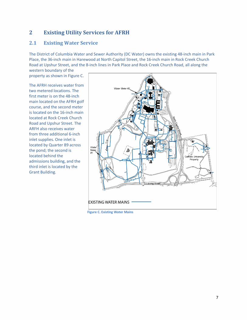
2.1 Existing Water Service The District of Columbia Water and Sewer Authority (DC Water) owns the existing 48-inch main in Park Place, the 36-inch main in Harewood at North Capitol Street, the 16-inch main in Rock Creek Church Road at Upshur Street, and the 8-inch lines in Park Place and Rock Creek Church Road, all along the western boundary of the property as shown in Figure C.
The AFRH receives water from two metered locations. The first meter is on the 48-inch main located on the AFRH golf course, and the second meter is located on the 16-inch main located at Rock Creek Church Road and Upshur Street. The ARFH also receives water from three additional 6-inch inlet supplies. One inlet is located by Quarter 89 across the pond; the second is located behind the admissions building, and the third inlet is located by the Grant Building.
Figure C. Existing Water Mains

8
There is an agreement between DC Water and the AFRH for DC Water to have a 15-million gallon underground reservoir on the AFRH’s golf course. This reservoir is supplied by an existing 48-inch water main that enters on the AFRH property from the south on Irving Street. The 48-inch water main that supplies the reservoir crosses through the center of Parcel D and its proposed building footprint. This water main was field surveyed by Greenhorne and O’Mara, Inc. in July 2009 as shown in Figure D. It is actually located approximately 24-feet to the east of its
alignment that is shown on the United States Soldier’s and Airmen’s Home, General Water Map prepared in 1994, however, the water line still crosses through the center of the proposed building footprint on Parcel D (see Figure L in Section 3.2).
Figure D. Surveyed 48-inch water main

9
2.2 Existing Sanitary Sewer Service The DC Water owns a 30-inch diameter combined sewer line under Irving Street at the south property line of Zone A. This line crosses through Parcel D and the proposed access point to Irving Street. From Irving Street a 30-inch diameter combined sewer line continues northerly into the site.
Based upon the land area of Parcel D, the proposed building footprint could be configured to avoid impacting the existing 30-inch sewer line. This redesign could also allow for additional open space to be used as a pedestrian plaza along the Irving Street entrance as recommended by the 2008 Master Development Plan (p. 107) (see Figure M).
A 15-inch sanitary main extends off to the northeast into the Zone A development area, passing south of the King Health Center and extending northwards to the Sheridan Building and other buildings located in the main campus as shown in Figure E.
The existing 15-inch line crosses under the proposed buildings located on Parcels K and M (see Figure O in Section 3.3), which will require the relocation of the sewer line or a redesign of the two buildings to maintain the current line configuration since this line provides service to AFRH buildings in the main campus. If the sewer line is relocated to avoid impacting Parcels K and M, it should be done to maintain the existing gravity flow of the system (see Figure P in Section 3.3). Any lines no longer in use should be abandoned and removed during construction of the parcels.
Figure E. Existing Sewer Lines

There is a ridgeline and drainage divide (Figure F) in the middle of the property to the west of Arnold Drive that runs longitudinally through the property which drains AFRH campus to the east and west. The buildings located on the east side of the drainage divide drain to the 30-inch combined sewer located at the Irving Street Gate and the buildings on the west side drain to the 10-inch sewer line at Rock Creek Church Road and Randolph Street. This drainage divide will have an impact on all future sanitary sewer and storm drain line designs in order to maintain gravity flow.
Figure F. Drainage Divide Map

2.3 Existing Stormwater Management The site drains towards the south, and runoff leaves the site in four locations as shown in Figure G. Systems of storm drains carry the runoff from the northeast portion of the site to the District of Columbia’s 54-inch storm drain pipe that runs along North Capitol Street. Runoff from the western portion of the site is carried via storm drain pipes and concrete flumes to the fishing ponds located in the southwest corner of the site. The fishing ponds discharge to an earth channel, which carries the water to a 42-inch storm drain pipe under Kenyon Drive. The 42-inch storm drain pipe is part of the District of Columbia’s storm drain system. The central portion of the site, from the Sherman Building to Irving Street, drains to a combined sanitary and storm drain sewer system that runs down the middle of the site. The combined sewer system connects to the District of Columbia’s system at Irving Street. The southeast portion of the site drains to a storm drain system, which flows south and connects to a 30-inch pipe under Irving Street near the North Capitol Street interchange. This pipe is part of the District of Columbia’s storm drain system.
According to DC Water, the Washington Hospital Center property has been prone to flooding after major storm events, which indicates inadequate capacity of the existing storm drain system that serves the AFRH and hospital. An analysis of the existing downstream storm drain system should be completed in conjunction with the first parcel developed to determine if adequate capacity remains for the new development of Zone A. If the lines are determined to be inadequate, it may require additional on-site water detention storage for storm events, or the existing downstream lines may need to be upsized to handle the increased stormwater from Zone A. Information regarding the proposed stormwater management for Zone A is included in Section 3.3.
Figure G. Existing Storm Drain System
12
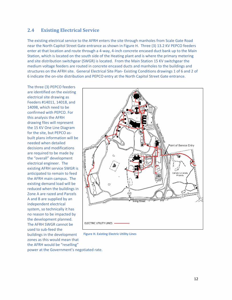
2.4 Existing Electrical Service The existing electrical service to the AFRH enters the site through manholes from Scale Gate Road near the North Capitol Street Gate entrance as shown in Figure H. Three (3) 13.2 KV PEPCO feeders enter at that location and route through a 4-way, 4-inch concrete encased duct bank up to the Main Station, which is located on the south side of the Heating plant and is where the primary metering and site distribution switchgear (SWGR) is located. From the Main Station 15 KV switchgear the medium voltage feeders are routed in concrete encased ducts and manholes to the buildings and structures on the AFRH site. General Electrical Site Plan- Existing Conditions drawings 1 of 6 and 2 of 6 indicate the on-site distribution and PEPCO entry at the North Capitol Street Gate entrance.
The three (3) PEPCO feeders are identified on the existing electrical site drawing as Feeders #14011, 14018, and 14098, which need to be confirmed with PEPCO. For this analysis the AFRH drawing files will represent the 15 KV One Line Diagram for the site, but PEPCO as-built plans information will be needed when detailed decisions and modifications are required to be made by the “overall” development electrical engineer. The existing AFRH service SWGR is anticipated to remain to feed the AFRH main campus. The existing demand load will be reduced when the buildings in Zone A are razed and Parcels A and B are supplied by an independent electrical system, so technically it has no reason to be impacted by the development planned. The AFRH SWGR cannot be used to sub-feed the buildings in the development zones as this would mean that the AFRH would be “reselling” power at the Government’s negotiated rate.
Figure H. Existing Electric Utility Lines

13
It is anticipated that because PEPCO currently has feeders at the Scale Gate Road entrance, the new electrical service for the new development will be provided from this location. PEPCO needs to evaluate the available capacity that will exist on the three (3) feeders currently serving the AFRH to determine how they can utilize the remaining capacity to feed portions of the proposed development. General Electrical Site Plan- Demolition drawings 3 of 6 and 4 of 6 indicate the existing distribution that will be affected by the proposed development. The following issues need to be addressed because they affect the continuity of service to occupied AFRH buildings on-site.
1. When Parcel “H” is developed, it will impact PEPCO’s service entrance manhole (MH#3).
The existing manhole will be in the parcel area and the duct bank routing up to PEPCO
manhole MH#2 passes through the building’s footprint. Unless the building is repositioned
or is reduced in size (footprint), it will require that the PEPCO service to the AFRH be
reworked from existing PEPCO manhole MH#4 up to existing MH#2.
2. There are a number of AFRH buildings along the east side of the site that will need to be
demolished in order to enable the Phase II & III parcels to be developed. The 15 KV feeders
that exist in those parcels will need to be isolated from the AFRH distribution system and
manholes and duct banks removed.
Per conversations with AFRH facility personnel, the existing buildings associated with the King Health Center are to be vacated and made available for development in approximately 2013. The parcels to be developed are identified on the electrical plans as, “A”, “B”, “B1”, and “B2”. These buildings are fed through the manholes/duct banks described above. Until Parcels “H”, “K”, or “M” are developed, electrical services to these buildings can be maintained for purposes of preservation, if desired.
3. Existing AFRH Building 48 was identified to be retained by the AFRH. It apparently provides
power to site lighting associated with Realigned Arnold Drive. This building will become
isolated from the AFRH electrical service at the time the King Health Center buildings are
decommissioned. Refer to General Electrical Site Plan- Revised drawings for our
recommended approach to supplying permanent power to that structure.
4. During our meetings with AFRH facility personnel, it was mentioned that the Heating Plant
was going to be taken off-line in the near future. Discussion ensued that there was thought
given to including that as an additional development parcel. If so, AFRH may need to
relocate the AFRH 15 KV service equipment. At a minimum, rights-of-way for existing
distribution through that parcel must be established in whatever arrangement is made.

14
2.5 Existing Natural Gas Service Natural gas service to the AFRH is provided by the Washington Gas Company with service locations on the east and west sides of the AFRH as shown in Figure I. An existing 4-inch service line operating at 17 to 20 pounds per square inch (psi) enters the AFRH from the east, just north of Scale Gate Road after passing under North Capitol Street. This service is currently routed around the ARFH campus and supplies multiple buildings including the Heating Plant 46, LaGarde Building 58, Barns Building 52, Quarters 47, King Hall 59 and Building 45. These buildings, with the exception of Building 45,will be turned over for development, demolished or otherwise disconnected from gas service by approximately 2013 as part of Development Zone A. The existing gas mains are owned and maintained by the Washington Gas Co. Connections from this main to individual buildings are locally metered. The existing gas mains are indicated on drawings “General Gas Site Plan, Existing Condition 1 of 6 and 2 of 6.” There is currently no gas service on the south side of Development Zone A along Irving Street. Washington Gas has indicated that there are currently no gas mains available on either side of Irving Street. The Washington Hospital Center is fed from Michigan Avenue to the south. There is a proposed gas main indicated on the Gas Company’s utility plans on the south side of Irving Street. The purpose for this line is currently being investigated by Washington Gas. In preliminary discussions the gas company has indicated that its preferred service development is from the
Figure I. Existing Natural Gas Lines

15
existing service on North Capitol Street. However, if the demand for natural gas is sufficient, the utility will accommodate the site with additional services as required.

16
3 Proposed Utility Service for Zone A
3.1 Proposed Phasing Alternatives This Utility Master Plan was prepared for two alternatives, Alternative A and Alternative B, described in Section I. The proposed utility plans for each are described below: Alternative A: The phasing of the Alternative A infrastructure development for Zone A as shown on Figure B is based upon site topography and the location of existing utility services that must either be extended or be tapped into to provide service to the new buildings. To support this phasing, two new water lines will be provided from separate connection points, one connection will be from Michigan Avenue at Irving Street, and the second from a point from Harewood Road. The Harewood Road connection can occur at two possible locations- a northern location and southern location. The northern alignment would cross through the Catholic University in an existing Washington Gas easement and enter onto Zone A at the Scale Gate Road entrance; the southern alignment would cross through the center of the Catholic University property and onto Zone A to the north of Parcel F. The new sewer would tie into the existing 30-inch sewer main that runs through the center of the campus; the storm drain would drain to the two existing lines in the south and southeast sections of the site to drain off-site; electric would extend from Irving Street and natural gas would enter from the North Capital Street Gate, unless Washington Gas installs a new line in Irving Street to Zone A.
Beginning development in the southern section will establish the utility connections and alignments that the later development phases must follow. Once Phase I is complete, Phase II development would begin in the center section. The roads and utility services can be extended northward, as needed, to serve the parcels within this zone. Then the linear progression of utilities can extend towards the northern section, Phase III, as necessary to serve its parcels. Alternative B: The second phasing alterative, Phasing Alternative B, follows the guidance contained in the approved Master Plan (page 146 of Master Plan). The first phase of development for Alternative B includes Parcels C, D, E, F, T and S. Beginning development on Parcels C and D will establish the utility alignments that the remaining parcels will follow for their utility design. The utility connections will be the same as described for Alternative A.
The second phase will include Parcels A, B, B1, B2, H, I, K and M located in the northern section. Depending on the water alignments constructed in Phase I, Phase II may have the benefit of tapping directly into a new water line if the northern alignment was constructed. If the southern option is selected then Phase II must extend the water lines northward along Pershing Drive and Pasture Road as necessary. Sewer would be provided by installing a line that would run between Parcels H, I, K, and M. The remaining center section parcels will create the final phase. Starting development in the northern phase will create the second main vehicular access point onto Zone A from Scale Gate Road and North Capitol Street. This access point can capture traffic traveling from points north of the AFRH, and will provide a direct route to the LaGarde Building. The second entrance may also provide for an even distribution of trips entering and exiting the site on two roads, rather than all trips entering and exiting from one entrance.

17
Parcels A, B and B2: Parcels A, B, and B2, which are existing buildings, may have the benefit of utilizing their existing water, sanitary and storm sewer lines to continue those services, but new electrical and natural gas lines will be required. Prior to the reuse of those three buildings the AFRH will sever existing utility connections to these buildings in order to separate utility systems. When the water service is separated from these buildings it must be done in a manner and timing in order to maintain the existing fire hydrant coverage. A physical inspection of the water, sanitary sewer and storm drain lines should be performed prior to beginning engineering and rehabilitation of the buildings to ensure that these lines are structurally sound and not deteriorating to the point where they can no longer be used. If these parcels are developed in Phase I, or in Phase II under Alternative A, then road access extending from the Irving Street entrance or the Scale Gate Road entrance must be provided.
18
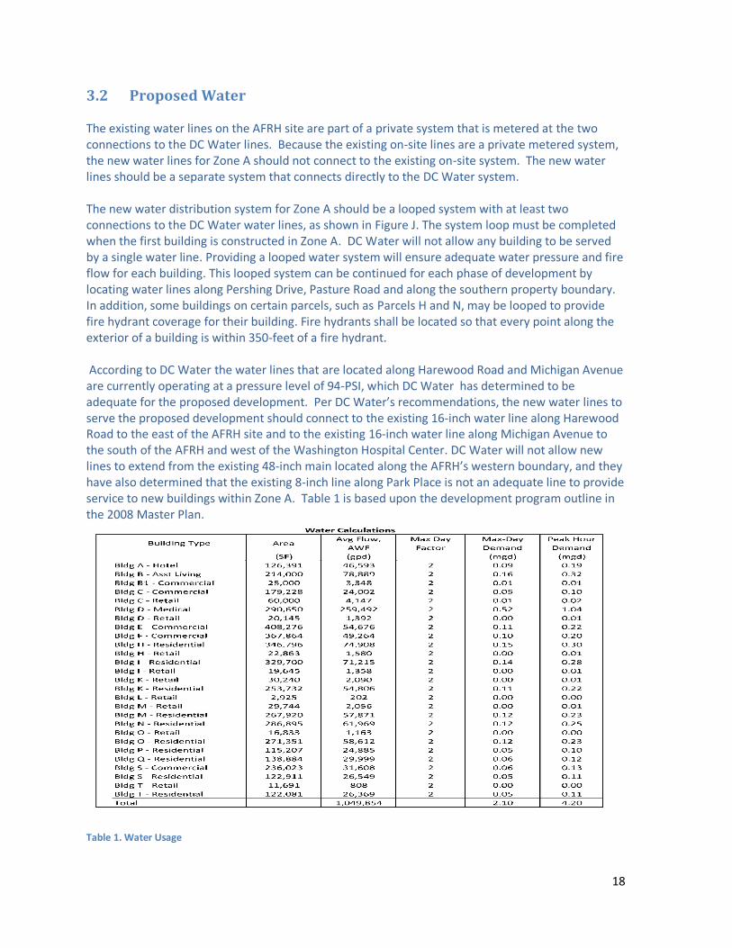
3.2 Proposed Water The existing water lines on the AFRH site are part of a private system that is metered at the two connections to the DC Water lines. Because the existing on-site lines are a private metered system, the new water lines for Zone A should not connect to the existing on-site system. The new water lines should be a separate system that connects directly to the DC Water system. The new water distribution system for Zone A should be a looped system with at least two connections to the DC Water water lines, as shown in Figure J. The system loop must be completed when the first building is constructed in Zone A. DC Water will not allow any building to be served by a single water line. Providing a looped water system will ensure adequate water pressure and fire flow for each building. This looped system can be continued for each phase of development by locating water lines along Pershing Drive, Pasture Road and along the southern property boundary. In addition, some buildings on certain parcels, such as Parcels H and N, may be looped to provide fire hydrant coverage for their building. Fire hydrants shall be located so that every point along the exterior of a building is within 350-feet of a fire hydrant. According to DC Water the water lines that are located along Harewood Road and Michigan Avenue are currently operating at a pressure level of 94-PSI, which DC Water has determined to be adequate for the proposed development. Per DC Water’s recommendations, the new water lines to serve the proposed development should connect to the existing 16-inch water line along Harewood Road to the east of the AFRH site and to the existing 16-inch water line along Michigan Avenue to the south of the AFRH and west of the Washington Hospital Center. DC Water will not allow new lines to extend from the existing 48-inch main located along the AFRH’s western boundary, and they have also determined that the existing 8-inch line along Park Place is not an adequate line to provide service to new buildings within Zone A. Table 1 is based upon the development program outline in the 2008 Master Plan.
Table 1. Water Usage

19
Alternative A To supply water to Phase I the water connections should be established at the DC Water recommended Michigan Avenue and Irving Street location, and Harewood Drive location. The new water lines extended to Zone A should be 12-inch in diameter at a minimum; however, during the engineering phase of the first building it may be revealed that a larger diameter line is needed to support the development. There are two connection options along Harewood Drive- a northern alignment and a southern alignment. The northern alignment, Option 2 as shown on Figure J, would cross through the Catholic University property in an existing Washington Gas easement and enter onto Zone A at the Scale Gate Road entrance. The northern alignment is proposed to tie into the existing 12-inch water line located on the east side of the LaGarde building. This existing 12-inch line travels south of the LaGarde Buildings and transitions into an 8-inch line leading to Parcel D, which will need to be upgraded to a 12-inch line. The northern alignment will also establish the new water connection for the LaGarde Building, which could allow this building to be offered for redevelopment in Phase I. The southern alignment, Option 1, would cross through the center of the Catholic University property and onto Zone A to the north of Parcel F. Option 1 will require an easement from the Catholic University to construct the water line on the University’s property. If either Option 1 or 2 or not feasible for any reason, it may be an option to construct a water line from the Harewood Drive and Michigan Avenue intersection and run the new water line to Zone A within the road right-of-ways. Extending two water lines to Zone A is required by DC Water for the construction of the first building in Phase I in order to maintain a looped system. Once the two initial 12-inch water lines have been constructed for the first developing parcel, the lines can be extended northward in the Pershing Drive and Pasture Road right-of-way as needed to supply water to the remaining Parcels in Phase I, Phase III, and Phase III. Based upon the anticipated development it is expected that the water lines in Zone A will range from 8 to 12-inches. The 12-inch line should be installed in the Pershing Drive right-of way and the 8-inch line will run in the Pasture Road right-of-way. DC Water has requested that if the roads within Zone A are privately owned, then a curb-to-curb easement be granted to them for maintenance of the lines. Alternative B The initial water connections for Phase I will follow the same connection options as described in Alternative A. To supply water to Phase II if Option 1 is selected for Phase I, both water lines must be extended northward within the Pershing Drive and Pasture Road right-of-ways, through Phase III, to the developing parcel. The later developing parcels in Phase I will be required to extend and loop the water lines as necessary. If Option 2 is selected then the developing parcel will have the benefit of tapping into the 12-inch line that was constructed in Phase I and only one line will need to be extended from Phase I. As later parcels are developed in Phase II they will be required to extend water lines as necessary to continue the looped system. Since Phase III is located in the center of Zone A, they will be able to extend water lines that were constructed during Phase I and Phase II either from the north or south, depending on the developing parcels location. The water lines to serve these parcels must be extended and connected to continue the looped system as shown in Figure J.

20
Figure J. Proposed Water System Plan

21
Water Service Constraints within the 2008 Master Plan for Development: Parcel D has been identified as having potential development conflicts with the existing water and sanitary sewer services:
Parcel D: Figure K illustrates the following conflicts with the proposed building footprint on Parcel D, per the 2008 Master Plan: 1. The location of the existing 48-inch water
main that feeds the AFRH’s underground reservoir, and
2. The existing 30-inch combined sanitary sewer main that serves buildings located in the main campus.
Both of these mains cross beneath the proposed building footprint shown on Parcel D. DC Water has indicated that these two lines could be relocated to allow for the building as shown in the Master Plan, but there is a significant cost associated with that task. To relocate the water line alone will cost approximately $605,332. DC Water has also indicated that the 48-inch water main has issues with leaking. If the water main is re-aligned (Figure L) it should be placed in the Arnold Avenue right-of-way. If the sewer main is re-aligned to avoid impacting the building it should be set back a minimum of 20-feet from the building.
Figure K. Parcel D Water and Sewer Conflict
Figure L. Parcel D Water and Sewer Relocation

22
Development Recommendation - Parcel D: Provide an alternate building footprint (Figure M) to avoid impacting the existing water and sewer mains. DC Water will require a minimum five-foot building setback from the 48-inch water main, but due to known leaks in the water line it is recommended to have a minimum 20-foot building setback or greater. The alternate footprint shows a 67,797 square foot building footprint. A five-story building with this footprint will provide a 338,985 gross square foot building. This footprint provides room for a large outdoor pedestrian plaza along the main entrance that can expand the planned gateway into Zone A. This gateway can be enhanced through sitting areas, landscaping, and artistic features. The use of permeable pavers or permeable concrete could also be employed in the plaza to reduce storm water management requirements. Based upon the deteriorating condition of the water line and potentially significant cost of relocating the water main, modifying the building footprint to avoid impacting the water main is a preferred option.
Figure M. Parcel D Alternative Building Footprint

23
3.3 Proposed Sanitary Sewer A new 8-to 10-inch gravity sanitary sewer line is proposed to carry flow from the north end of Zone A to the south and west along the proposed Pershing Drive to connect into the existing 30-inch combined sewer that runs through the center of the AFRH campus along Arnold Drive as shown in Figure N. This 30-inch line may need to be upgraded to a 48-inch line since it is a combined sewer line and buildings located on the main campus will continue to utilize this line for sanitary and storm water. All new buildings in Zone A are expected to connect into this sewer line since there are no sanitary sewer lines to connect into along North Capitol Street. Based upon the development program described in the 2008 Master Plan a sewage usage table was prepared (Table 2)
Table 2. Sanitary Sewer Usage
Alternative A Based upon topography and existing sewer location, it is ideal to begin Phase I development in the southern parcels. Development of these parcels will establish the framework for the new sewer line to serve the remainder of Zone A. Phase I will require a 10-inch sewer that should be constructed in the Pershing Drive right-of-way. This 10-inch sewer will extend to Parcel E and T where it will transition down to an 8-inch line. The 8-inch sewer line will continue in a linear progression along Pershing Drive to serve the remaining parcels in Phase I, Phase II and Phase III.

24
Alternative B Phase I for this alternative will follow the same alignment as described for Alternative A. Developing the northern parcels as Phase II will require an 8-inch sewer line between Parcels K and M to connect into the existing 15-inch terra cotta sewer line located to the east of the LaGarde Building, as shown on the Conceptual Sewer Plan Sheet 3 of 4. The condition of this line is not known, therefore it is recommended to have the line examined by a certified sewer inspector to determine if the line can be used for the new development. Depending on the condition of the line a new sewer line may be needed to replace this existing sewer line. Sewer service for Phase III will be completed by extending an 8-inch line from the 10-inch line constructed in Phase I northward along the Pershing Drive right-of-way. For both Alternatives, Building B1 will be required to construct a 6 to 8-inch sewer and connect into the existing 8-inch sewer line located to the immediate east of the LaGarde Building as shown in Figure N. An existing 8 to 15-inch terra cotta sanitary sewer line that branches off the main 30-inch sewer line to serve multiple buildings in the main campus runs through the center of Parcels K and M, and the line will need to be re-routed to the north of Zone A to connect into the parallel 30-inch combined sewer line to continue sewer service to those buildings in the main campus.

Figure N. Proposed Sanitary Sewer System

26
Sewer Service Constraints within the 2008 Master Plan for Development: An area has been identified as having potential development conflicts with the existing sanitary sewer services:
Parcels K & M: This area conflict is where the existing 8 to 15-inch sanitary sewer line crosses beneath the proposed buildings on Parcels K and M (Figure O). This existing line is important since it serves buildings located in the main campus, and must be re-aligned prior to development on either Parcel K or M.
Development Recommendation-Parcels K & M: In order to accommodate the new development on Parcels K and M, a new 8-inch sewer line should be installed to the north of Zone A to maintain sewer service to the main campus buildings. Based on site topography and locations of other existing sewer lines there is an option to construct a new sewer line at manhole #25 to a point on the parallel 30-inch combined sewer as shown in Figure I. This sewer layout is conceptual and additional engineering studies may reveal a different re-alignment.
o Figure P shows a new sewer line near manhole #25 as shown on the 1994 General Sanitary Sewer Map, to run southwest until it ties into the existing 30-inch combined sanitary sewer line to the north of Marshal Drive.
Figure O. Parcel K and M Sewer Conflict
Figure P. Alternative Sewer Plan

27
3.4 Proposed Stormwater Management
3.4.1 Technical Requirements This project must meet the requirements of the District of Columbia and Section 438 of the 2007 Energy Independence and Security Act (EISA) for both quantitative and qualitative stormwater management for the new development as shown in Figure Q. Section 438 is applicable to any federal agency that is a sponsor of a development or redevelopment project. The sponsor is regarded as the federal department or agency that owns, operates, occupies, or is the primary user of the facility and has initiated the development or redevelopment project.
DDOE Requirements: The District of Columbia regulations for quantitative management require that the 2- and 15- year peak discharges after development is reduced to pre-development condition levels. For qualitative management, the first 0.5-inches of runoff from streets and parking lots, and 0.3-inches for rooftops, sidewalks and plazas impervious area must be treated. At this time the District of Columbia is re-writing its stormwater management manual and regulations may change when development on Zone A begins. Section 438-of EISA: Section 438 requires the use of site planning, design, construction, and -maintenance strategies to maintain or restore the pre-developed hydrology to the maximum extent technically feasible. The use of Leadership in Energy and Environmental Design (LEED) practices must be used in storm water quantity control to prevent post-development peak discharge and quantity from exceeding pre-development rates for the 1- and 2-year, 24-hour storms, and in storm water quality control to treat runoff from 90-percent of the average rainfall using Best Management Practices (BMPs) capable of removing 80-percent of the average annual post development total suspended solids. The rainfall amount that must be treated to meet this requirement for Washington DC is 1.7”. If Section 438 requirements are met (or even partially met) the Washington, DC water quality requirements will also be met. For quantity control it may be necessary to provide treatment through bioretention for a portion of the 2- and 15-year storm control.
Stormwater Management Guidance and Requirements
Section 438 of the Energy Independence and Security Act of 2007 (EISA)
EPA’s Technical Guidance on Implementation of Section 14 of Executive Order (EO) 13514, Federal Leadership in Environmental, Energy, and Economic Performance
Executive Order (EO) 13514, Federal Leadership in Environmental, Energy, and Economic Performance
Executive Order (EO) 13423, Strengthening Federal Environmental, Energy, and Transportation Management
District of Columbia Department of the Environment, Storm Water Management Regulations (District of Columbia Municipal Regulations (DCMR) Title 21, Chapter 5) and Requirements of DDOE Stormwater Guidebook
LEED, Version 3.0, LEED ND, Neighborhood Development
Figure Q. Stormwater Mgt. Guidance and Requirements.

28
Impact of Development to Stormwater Management in Zone A: Most of the runoff from Zone A is directed towards the existing 30-inch storm drain line at the Irving Street and North Capitol Street interchange, while the southwest corner of the development is directed towards the existing 30-inch combined line located in the middle of the property. Table 3. Pervious and Impervious Development Table, Alternative A. To accommodate the full development potential of Zone A, a wide range of storm drain pipes will be required ranging from 18 inches to 48 inches. Table 3, which follows the phasing of Alternative A, provides approximate acreages for the proposed impervious and pervious area of each phase. The acreages listed for Phase II and Phase III are switched for Alternative B. Low Impact Development: The amount of runoff diverted to the storm drain pipes should be minimized to the greatest extent possible through the use of Low-Impact Development techniques. These techniques should be utilized for all three phases of development. During the engineering phase for the buildings the reduction of impervious area should be analyzed to determine the exact storm water quantity and quality controls that will be required for each building and phase of development. The retention of stormwater is especially important since DC Water indicated that the existing storm drain system may have inadequate capacity, and different retention techniques should be applied to mitigate the problem to the best extent practical.
The 2008 Master Plan recommends providing two stormwater management ponds to satisfy quality and quantity control requirements for Zone A, but current stormwater management and low-impact development techniques encourage the use of a decentralized stormwater management system in place of the traditional pond. The use of a stormwater pond could be proposed by a potential developer, but its approval by the local government is not guaranteed. A decentralized system can be achieved by providing bioretention areas throughout the development. The use of green roofs is another low-impact development option that can be employed.
Phasing: Stormwater management technologies can be constructed in conjunction with each phase, or with each building as shown in Figure K. If the roadway infrastructure is constructed prior to construction of the buildings, the Best Management Practices (BMPs) such as bioretention, in the roadway area will
Phase Acreage Proposed Impervious
Acreage
Proposed Pervious Acreage
Phase I 22 Acres +/-
20.2 Acres+/- 1.8 acres+/-
Phase II 12 Acres+/- 10.4 Acres+/- 1.2 Acres+/-
Phase III 43 Acres+/- (Pasture = 20+/- acres)
18.4 Acres+/- (includes ex. impervious
area)
24.6 Acres+/-

29
need to be constructed with the road and will need to be protected from becoming contaminated with silt and other debris during building construction.

30
Figure R. Proposed Stormwater Management Plan

31
Existing Topography Directs Sequence of Stormwater Drain Line Construction for New Development in Zone A: Since Zone A drains towards the south, the development of Phase I will require the installation of the largest diameter storm drain lines in order to provide adequacy for Phases II and III since they too will drain into the same storm drain system as shown in Figure R. The new lines will connect into the existing storm drain system at two locations. The first connection will be at the existing 42-inch storm drain line at the Irving Street and North Capitol Street interchange, and the second connection point will be at the 30-inch line located in the middle of the property off of Irving Street as shown on the Conceptual Stormwater Management Plan Sheet 1 of 8. Parcels E, F and T drain to the 30-inch line at the North Capitol Street interchange. A proposed 42-inch line that runs between the Parcels E and F will be the main receiving storm drain line for almost all of the development proposed for Zone A. Extending from this 42-inch line is a 30-inch line that will travel northward along Pershing Drive towards the other phases of development. This main receiving storm drain line will also take water from a second 18-inch to 24-inch storm drain line which runs parallel to the proposed Pershing Drive.
The buildings on Parcels C and D will drain to the 30-inch combined sanitary and storm drain line located in the middle of the property that will need to be upgraded to a 48-inch line since it must also serve buildings located on the main campus. This 48-inch line may need to be extended approximately 400-feet south on to the Washington Hospital Center property to connect to an existing 48-inch combined sewer line. Depending on the final building footprint on Parcel D and the condition of the combined sewer and storm drain this line may need to be relocated. Alternative A Phase I: For Phase I development the following storm drain lines must be installed: the 48-inch line between Buildings C and D, the 30-inch line along Pershing Drive from Building E to Building F at Pershing Park, the 18-inch line to the north of Building T, and the 30-inch and 42-inch line that extends from the 18-inch line to the connection at the Scale Gate Road/North Capitol Street interchange.
Phase II: The second phase will be served primarily by the 30-inch storm drain line that will extend from the northern Limit of Phase I at Pershing Drive northward. A secondary 24-inch line will also be needed and will follow the alignment of the parallel road. The storm drain lines for this phase will extend between the lines of Phase I and Phase III.
Phase III: The main 24-inch storm drain line to serve Phase II will continue from the proposed Pershing Drive. A secondary line will also be needed and will follow the alignment of the parallel road. The storm drain lines for this phase can extend to the centerline of the secondary road to the south of Buildings M and I. This will allow for easy connection for the future development phase. Alternative B: Phase I: For Phase I development the following storm drain lines must be installed: the 48-inch line between Buildings C and D, the 30-inch line along Pershing Drive from Building E to Building F at Pershing Park, the 18-inch line to the north of Building T, and the 30-inch and 42-inch line that extends from the 18-inch line to the connection at the North Capitol Street interchange

32
Phase II: This phase will require the extension of the 30-inch storm drain within Pershing Drive and 24-inch line within Pasture Road. These lines can be transitioned down to a 24-inch line and 18-inch line once in the limits of Phase II. Phase III: The parcels in this phase will have the benefit of tying directly into the 30 and 24-inch storm drain lines that were installed to serve Phase II. Stormwater Management without Vegetated Roofs: To treat the center and northern section parcels having buildings without green roofs, a minimum of four bioretention facilities will be required in the pasture ranging from 7,500 square feet to 10,000 square feet. Flow splitters will be required at the proposed bioretention areas to divert the appropriate stormwater discharge to the bioretention facility. Assuming the northern section develops as Phase II (Alternative B), it will be the responsibility of the first developer to install the storm drain piping to the first bioretention area and construct a proportionally sized bioretention facility needed to treat the respective parcel. As later development occurs on other parcels, the bioretention ponds will need to be increased in size as needed to treat the additional stormwater. The storm water from the northern sections will be conveyed to the bioretention ponds by an 18-inch storm drain pipe that extends from the north of Parcel H to the south along Pershing Drive until the southern boundary of Parcels M and I. The storm drain line will then run west towards the pasture and to the bioretention areas. These bioretention facilities will ultimately drain to the 42-inch storm drain line located in the southeast corner of Zone A as shown on the stormwater management plan sheet 3 of 8. The use of traditional stormwater ponds may also be an option, if bioretention is not feasible. These ponds can be constructed and sized in a similar fashion to the bioretention facilities. Parcel B1 will drain to an existing storm drain located to its immediate north. The run-off for this parcel will be treated by bioretention and underground storage.
The center section parcels will require a storm drain line to be constructed in the road to the north of Parcels N and O and Parcels Q and P. These lines will drain from east to west and outfall into the bioretention ponds in the pasture. The southern section parcels are located downhill of the bioretention areas and cannot drain to them, and therefore no change to the proposed storm drain system is needed. Bioretention ponds should be installed where possible.
3.4.2 Low Impact Development: Sustainability
Implementation of Section 438 (2007) can be achieved through use of green infrastructure/low impact development (GI/LID) infrastructure tools. The following is list of some of the tools that might be used or considered for development of Zone A:
Green roof (per Master Plan page 105): A green roof or partial green roof should be considered for each of the proposed buildings. A media thickness of 4.25” under the green roof will meet the 1.7” requirement for that portion of the roof (at 40% void ratio).
If green roofs are not utilized for stormwater treatment then additional bioretention areas will be required throughout the entire development as previously discussed. In some cases this may require a reduced building footprint to achieve the storm water management requirements.

33
Bioretention: Available green space should be considered for utilization as bioretention (functional landscape, Figure S). Structural bioretention such as planter boxes, or tree boxes (Figure T) could also be used. Bioretention is proposed in all three phases.
Figure S. Typical Bioretention Detail
Figure T. Typical Filterra Detail

34
Pervious Pavement: Pervious pavement cannot be utilized for roadways. Pervious pavers or pervious concrete could be utilized for sidewalks or plaza areas, and the brick sidewalks referenced in the “Streets and Streetscapes” section of the 2008 Master Plan are considered pervious pavers.
Cisterns: Cisterns can be utilized for rainwater capture and reuse. Considerations for reuse would be toilet flushing, chiller water makeup, or possibly irrigation in the summer.
Site Planning: It is important to keep in mind that low-impact development is as much site planning as it is a storm water management design. From the start of site planning, efforts should be made to reduce impervious area, increase pervious area and utilize existing drainage patterns. Consideration for future development should be given to reducing pavement width, and even possibly eliminating some of the streets.
3.4.3 Sustainability Analysis and Recommendations It is encouraged that vegetated green roofs be used for all buildings in Zone A. If green roofs are not suitable for the buildings based upon building construction then cisterns can be used to capture roof water for reuse. The use of permeable pavers is also encouraged along all sidewalks, but a geotechnical report should be prepared to determine if the soil is suitable for permeable pavers. Also, all bioretention area should be planted with native, non-invasive species.
3.4.4 LEED Considerations for Design and Construction of Site
The 2008 Master Plan by Koetter, Kim and Associates indicates that Zone A has been accepted as part of a pilot program for LEED for Neighborhood Development by the U.S. Green Building Council. Because development did not proceed as scheduled, the project is no longer part of the program. However, the development of Zone A could potentially achieve a Gold Rating.
The recently released LEED Reference Guide for Neighborhood Development 2009 incorporates several credit categories which demonstrate principals of smart growth, site selection and design, and construction elements that integrate building and infrastructure. Credit Categories directly related to issues impacted by development of Zone A are:
Smart Location and Linkage: Both alternatives support first constructing the development areas at the locations that promote development at access points, and Alternative B may enhance the credit by providing the Scale Gate Road access earlier than Alternative A. According to the Master Plan, a proposal has been developed to provide shuttle services to Columbia Heights and Brookland/CUA Metro Stations. Alternative B will locate development first in the areas closest to access and assist with dispersing traffic.
Green Infrastructure and Buildings: Credit 8 relates to stormwater management. An integrated approach to design of the building and site with low impact design methods is preferred. The stormwater management practices in LEED ND support integrated approaches to evaluate and select designs for buildings and site using technologies to minimize the impact on water resources. An approach integrated with design of the site is critical to develop approaches that consider potable water use, groundwater, stormwater management goals, runoff harvest and reuse, infiltration and options such as greywater reuse. Options to achieve LEED certification for Zone A include the use of cisterns to capture rainwater for reuse, permeable pavers on sidewalks, and native plant species for landscaping.

35
Related Credit Categories:
Innovation and Design Process
Regional Priority
Neighborhood Pattern and Design

36
3.5 Proposed Electrical
Electrical will enter the site at two (2) points as shown in Figure U to support the development proposed; 1) Scale Gate Road entrance near the existing PEPCO AFRH service, 2) Irving Street entrance. The manhole and duct banks will be routed through the development in a manner to ultimately interconnect. A secondary loop of manholes along Pasture Road has been indicated to support the existing buildings to be renovated; Hotel (Building A), Assisted Living (Building B), and Buildings B1 and B2. General Electrical Site Plan- Revised drawings 5 of 6 and 6 of 6 indicate the proposed distribution described above. Alternative A Electrical service will enter on to the property first from Irving Street to supply Phase I. The PEPCO duct banks and feeders can be extended along the Pershing Drive right-of-way as necessary to supply the developing parcels in Phase I, and then into Phases II and III. The second service line from Scale Gate Road may be required during some point of development in Phase II, which would require the line to be constructed prior to beginning Phase III. If this occurs then the electrical line should follow the Pershing Drive right-of-way alignment. Alternative B Electrical service will enter on to the property first from Irving Street to supply Phase I. The service line can be extended northward along Pershing Drive as necessary to supply power to the other developing parcels in Phase I. To supply Phase II the second service line from the Scale Gate Road entrance would be installed. This service line would also be extended along Pershing Drive to supply the developing parcels in Phase II. For Phase III the electrical lines could be extended either from the north and south, depending on the location of the developing parcel. When the AFRH begins to sever electrical connections to Zone A, the AFRH will be required to reestablish the electrical connection to Building #48. The AFRH has two (2) alternatives to provide power to this building. The least expensive method would be to install an overhead pole line with a pole mounted “residential” type transformer. The alternate approach, which is more expensive, would be to trench an underground direct buried 15 KV feeder and install a transformer on a pad at the building.

37
Figure U. Proposed Electrical System

38
In order to discuss the electrical service that will be required to support the site, a spreadsheet was developed based upon the building usage and the square footage. The information provided total square feet by “space type”. The spreadsheet disseminated different “space types” to the buildings identified to contain those space types. This gives a parametric level utilization of how the energy load might be distributed throughout the site. Approximately 4.3 million SF of building construction is included in the spreadsheet (Table 4).
Utilizing accepted load profiles for buildings of these types, demands in watts/SF have been assigned. The results from this spreadsheet are:
1. PEPCO would likely need to provide four (4) 13.2 KV feeders to the site.
2. The buildings calculated load could be supported by secondary (low voltage) services. PEPCO
could develop sub-grade vaults, similar to its Downtown distribution grid to support the site
development. That would reduce construction cost to the developers.
Table 4. Electrical Usage

39
3.6 Proposed Natural Gas
In meetings and discussions with the Washington Gas Co. it was determined that Zone A would be served from the existing gas service entering the site from the east, north of Scale Gate Road passing under North Capitol Street. Washington Gas Co. has committed to routing the gas main as needed within Zone A to accommodate the selected phasing of development as it is finally determined, see Figure V. They will install the gas service line into or close to each parcel boundary. As each parcel is developed, the gas service into the building must be coordinated with Washington Gas to determine who will install the service, meter and regulator at the building. Therefore, for Phase I, Washington Gas Co. will extend the existing service and route the new gas distribution main to allow this Phase to be developed first. The new gas distribution main routing will be coordinated with the overall development plan to allow future phases of development to be implemented without disruption to the gas distribution main. This coordination will allow Washington Gas to eliminate and remove portions of the existing main yet allow them to extend the existing service to the various phases of development as they are scheduled to occur. The exact capacity of this service will need to be verified by Washington Gas and coordinated with the actual gas demands of the proposed structures in the areas of development. For the purpose of planning we have developed estimated daily gas demand for each structure based on survey data provided by the referenced source (Table 5). This information can be used in coordinating discussions with the utility regarding gas demand.
Table 5. Natural Gas Usage

40
-
Figure V. Proposed Natural Gas Service

41
4 Utility Coordination The development of the first parcel in Zone A will establish the progression for which all utility lines will be installed for Zone A. All lines should be installed in a linear fashion to avoid crossing utility lines and they should be extended to the limit of the road right-of-way that surrounds the developing parcel. This will allow for future developers to easily extend the utility lines without having too much impact on the existing developed parcels.
4.1 Water DC Water requires that no water line be tapped for service connection prior to DC Water’s written approval. To extend new water lines to Zone A, development must follow the Large Water Tap Insertions of the DC Water. According to DC Water, a Large Water Tap is required for any connection greater than 2 inches. The owner or developer is responsible for obtaining all proper permits, and is responsible for all construction associated with installing the new water line.
DC Water will extend water mains to serve a building upon request of the property owner or authorized agent. If a water main is not available, DC Water will extend the water main to the proposed point of connection with the water service line. It can take two years for the design, approval and construction of a water main.
If a water line must be abandoned, it shall be properly abandoned in accordance with DC Water requirements (at the applicant’s expense) to avoid leakage of water. The permit to abandon the line will not be issued until all water usage fees have been paid in full. The abandonment consists of removing the corporation stop and installing a plug in the tap, and the remaining service line will be left in place. Removal of the abandoned line will require DC Water approval. It will be the owner or developer’s responsibility to fund the abandonment and removal of the water lines. All work completed will be inspected by the Plumbing Inspection Branch, Building and Land Regulation Administration, and Department of Consumer and Regulatory Affairs.
4.2 Sanitary Sewer Written permission from DC Water is required prior to tapping into any of its sewer lines. The construction work for tapping into a sanitary sewer line is done by the applicant, and the inspection is done by DC Water Plumbing Inspection Branch, Building and Land Regulation Administration, and Department of Consumer and Regulatory Affairs.
DC Water will extend sanitary sewers to serve a building upon request of the property owner or authorized agent. If a sanitary sewer is not available, DC Water will extend the sanitary sewer line to the proposed point of connection with the sewer lateral. It can take two years for the design, approval and construction of a sewer extension.
DC Water requires that any sanitary sewer lines no longer required due to building demolition, or installation of a new sewer connection, be properly abandoned to avoid infiltration of ground water into the sanitary sewer system. Current regulations require a bulkhead to be placed on the sewer service connection at the property line or manhole if the service was connected to a manhole. The remaining service must be abandoned in place. Removal of the abandoned lines requires DC Water

42
approval. It is the responsibility of the property owner or developer to abandon the sewer lines and the completed work must be inspected by the Plumbing Inspection Branch, Building and Land Regulation Administration, and Department of Consumer and Regulatory Affairs.
4.3 Stormwater Management It is the responsibility of the District of Columbia, Department of the Environment to review and approve all stormwater management plans and storm sewer plans. If the proposed storm sewer lines tie into a public line then DC Water will also review and approve the plans. Any proposed storm sewer extension must be coordinated and approved by DC Water. It is the responsibility of the property owner or developer to extend or fund storm sewer to service new development.
Prior to submitting a stormwater management plan for large development projects to the DOE a meeting with its office is required. It typically takes approximately three to five months for the review and approval of stormwater plans. During the review of the stormwater plan the process for obtaining an Environmental Planning Agency (EPA) Construction General Permit (CGP) should begin by filing a Notice of Intent (NOI) with EPA. This general permit is required for any activity (clearing, grading, excavating, etc.) that disturbs one or more acres of land.
On February 1, 2010 new effluent limitations guidelines (ELGs) became effective to control the discharge of pollutants from construction sites. All construction sites must implement a variety of sediment and erosion controls and pollution prevention measures. After August 1, 2011 all construction sites that disturb 20 acres or more of land at one time are required to comply with the turbidity limitation of 280 nephelometric turbidity units (NTU). On February 24, 2014 this requirement will be applicable to all construction sites disturbing more than 10 acres.
4.4 Electrical
The formal process to initiate new electrical service from PEPCO is through Application for Class of Service. That process is essentially set up to submit a request for a specific building. The application provides PEPCO with detailed information about the building, the owner, the building street address, building size, and load breakdown by the different load types. The application for a new service requires a complete set of building plans that include the following:
1. Site plan with proposed transformer and meter locations 2. Grading plans showing parking areas, driveways, entranceways, etc. 3. Footing plans 4. Basement architectural plan 5. Ground floor architectural plan 6. Mechanical plan showing location of utilities entering building 7. Electrical plan showing service entrance room 8. Elevation views of building 9. Switchgear drawings (1200 ampere or more)
10. A 3.5" computer diskette containing all available CADD information in a DXF file format. (Note: This is not required, but will aid in expediting the processing of your request.)
As can be seen, the individual developers will be required to have their electrical engineer make this application and establish the formal arrangement for the specific building service. This process is not
43
really applicable to the AFRH’s multi-parcel development, particularly at this time in the master planning stage. The information provided in Table 4 and associated electrical drawings will be important in establishing initial contact with the PEPCO design engineers. The lead time for PEPCO to mobilize and initiate off-site infrastructure to support the proposed AFRH Development could significantly affect the project’s overall time frame. In order to initiate formal negotiations the site development electrical engineer will need to meet with PEPCO’s project distribution engineer to discuss the availability of service, entry points, on-site provisions, and costing.
4.5 Natural Gas Washington Gas will typically analyze the potential revenue stream of new services and if the results are favorable the utility will front all or some of the first cost of bringing gas mains onsite. In order to start this analysis, the gas company will request a load letter indicating the gas demand and occupancy for each planned structure. At a design level this demand would be in units of BTU/Hour. Because this project is at a concept level the Cubic Ft/Day units in the accompanying chart will be utilized.

44
5 Cost Estimates Two cost estimates were prepared for this master plan, one for Alternative A and another for Alternative B. Both estimates were analyzed at the phasing level and individual parcel level. The total cost of the water, sanitary sewer, stormwater management, natural gas, electric utilities for Alternative A is estimated to be $13,606,544. This price does not include the use of green roofs. If vegetated green roofs are used on the buildings under Alternative A, the cost will increase by $22,990,284 for a total development cost of $36,596,828. For Alternative B, the utility cost would be $13,680,984 without the use of green roofs. If green roofs are use then the cost will increase by an additional $22,990,284 for a total development cost of $36,671,268. All fees include estimated taxes, engineering fees, and a 3% annual escalation. For this analysis it was assumed that a developer would be responsible for installing the sections of utility lines that adjoin its parcel, with the exception of natural gas since Washington Gas has committed to installing their lines to service Zone A. The construction costs may change if the utility lines are already in installed as the result of another construction project. It is assumed Parcel D will be the first parcel developed. This will require the developer to install the new water mains from the connection points discussed in Section 3.2. For this study, three alignment options were reviewed. The first alignment would establish a connection point at Michigan Avenue and Irving Street, and the second point would be established at either a northern (Option “2”) or southern (Option “1”) location on Harewood Road. The cost estimate for Alternative A analyzed the cost associated with Option “2”, and the cost estimate for Alternative B analyzed the cost of the Option “1” alignment. Alternative A: Phase I: Based on current construction and material costs it is estimated that it will cost approximately $7,687,623 to construct all utilities for Phase I. The cost per parcel will increase if vegetated green roofs are utilized. The estimated cost also includes taxes, engineering, and 3% annual escalation.
Parcel C: $1,312,393 (+ $2,319,701for green roof)
Parcel D: $2,639,082 (+ $2,324,067 for green roof) (Option “2” water alignment priced and, cost of 48-inch water main included)
Parcel E: $997,972 (+ $2,613,870 for green roof)
Parcel F: $965,882 (+ $1, 645,718 for green roof)
Parcel T: $1,085,140 (+ $1,029,217 for green roof)
Parcel S: $687,155 (+ $2,154,446 for green roof)

45
Phase II: Based on current construction and material costs it is estimated that it will cost approximately $2,291,529 to construct all utilities for Phase II. The estimated cost also includes taxes, engineering, and 3% annual escalation.
Parcel N: $496,586 (+ $1,364,313 for green roof)
Parcel O: $803,387 (+ $1,978,231 for green roof)
Parcel P: $525,377 (+ $689,895 for green roof)
Parcel Q: $465,730 (+ $1,015,354 for green roof)
Phase III: Based on current construction and material costs it is estimated that it will cost approximately $3,627,392 to construct all utilities for Phase III. The estimated cost also includes taxes, engineering, and 3% annual escalation.
Parcel A: $21,121
Parcel B: $421,170
Parcel B1: $165,755
Parcel H: $813,540 (+ $1,100,389 for green roof)
Parcel I: $637,103 (+ $1,798,563 for green roof)
Parcel K: $835,519 (+ $1,522,683 for green roof)
Parcel M: $733,184 (+ $1,433,927 for green roof)
Alternative B: Phase I: Based on current construction and material costs it is estimated that it will cost approximately $7,762,063 to construct all utilities for Phase I. The cost per parcel will increase if vegetated green roofs are utilized. The estimated cost also includes taxes, engineering, and 3% annual escalation.
Parcel C: $1,311,201 (+ $2,319,701for green roof)
Parcel D: $2,718,104 (+$ 2,324,067 for green roof) (Option “1” water alignment priced and, cost of 48-inch water main included)
Parcel E: $ 997,067 (+$ 2,613,870 for green roof)
Parcel F: $ 965,005 (+$ 1,645,718 for green roof)
Parcel T: $ 1,084,155 (+$1,029,217 for green roof)
Parcel S: $ 686,531 (+ $2,154,446 for green roof)

46
Phase II: Based on current construction and material costs it is estimated that it will cost approximately $3,627,392 to construct all utilities for Phase II. The estimated cost also includes taxes, engineering, and 3% annual escalation.
Parcel A: $21,121
Parcel B: $421,170
Parcel B1: $ 165,755
Parcel H: $ 813,540 (+$ 1,100,389 for green roof)
Parcel I: $ 637,103 (+$ 1,798,563 for green roof)
Parcel K: $ 835,519 (+$ 1,522,683for green roof)
Parcel M: $ 733,184 (+$ 1,433,927 for green roof)
Phase III: Based on current construction and material costs it is estimated that it will cost approximately $2,291,529 to construct all utilities for Phase III. The estimated cost also includes taxes, engineering, and 3% annual escalation.
Parcel N: $ 496,586 (+$ 1,364,313 for green roof)
Parcel O: $ 803,837 (+$ 1,978,231 for green roof)
Parcel P: $ 525,377 (+$ 689,805 for green roof)
Parcel Q: $ 465,730 (+ $ 1,015,354 for green roof)
The cost estimate prepared by M.A. Associated dated October 21, 2010, included in the appendix, provides the more detailed cost estimate for each parcel.

47
APPENDIX