AFM - Thermo Mechanical Writing
10
JOURNAL OF MICROELECTROMECHANICAL SYSTEMS, VOL. 11, NO. 6, DECEMBER 2002 765 Design of Atomic Force Microscope Cantilevers for Combined Thermomechanical Writing and Thermal Reading in Array Operation William P. King, Thomas W. Kenny , Member , IEEE , Kenneth E. Goodson , Associate Member , IEEE , Graham L. W. Cross, Michel Despont, Urs T. Dürig, Hugo Rothuizen, Gerd Binnig, and Peter Vettiger , F ellow, IEEE Abstract—In ther momechanical data wr it ing, a re si s- tiv el y-heat ed atomic forc e mic rosco pe (AFM) can til ever tip forms indentations in a thin polymer film. The same cantilever operates as a thermal proximity sensor to detect the presence of previously written data bits. This paper uses recent progress in thermal analysis of the writing and reading modes to develop new canti lev er desig ns for incr eased speed, sens itivi ty , and red uced power consumpti on in bot h wri tin g and re adi ng ope rat ion . Measurements of cantilever electrical resistance during heating rev eals physical limits of canti leve r writ ing and rea ding, and veri fie s a fin ite-d iffe ren ce ther mal and elec tric al simul ation of canti lev er opera tion. This work proposes two new canti lev er desi gns that corr espon d to fabri catio n techn ology benc hmark s. Simulations predict that the proposed cantilevers have a higher dat a rat e and ar e mor e sen sit ive than the pr ese nt cantil ever . The vari ous canti lev er desi gns offer single- bit writi ng times of 0.2 s–25 s fo r dr ivin g vol tages of 2–2 5 V . The ther mal r eadi ng 1 sen sit ivi ty is as hig h as 4 10 4 per vertical nm in near steady-state operation. Analysis of the adaptable operation of a single cantilever bounds the operation of a cantilever array. The pre sent cantile ver operate s with an array data rate as high as 35 Mbit sec 1 at a power of 330 mW and can operate at less than 100 mW. Proposed cantilevers offer a factor of 10 improvements in both data rate and power consumption. By considering their thermal, mecha nica l and elec tric al desi gn, and by optimi zing cantilevers for both writing and reading, this work aims to guide the future development of AFM cantilevers for thermomechanical data storage systems. [774] Index T erms—Atomic force microsc ope (AFM) , data stora ge, microscale heat transfer, thermal engineering. I. INTRODUCTION T HE VARI ETY of applications of atomic force microscopy for the measurement of small features [ 1], [2] and for highly local surface modification [ 3]–[5] have brought atomic Manuscript received November 4, 2001; revised April 22, 2002. The work of W. P. King was supported by an IBM Graduate Research Fellowship. Subject Editor O. Tabata. W. P. Kin g is wit h the Wood ruf f Sch ool of Mec han ical Eng ine eri ng, Geor gia Instit ute of Te chnology, Atlan ta, GA, 3033 2-04 05 USA (email : [email protected]) T. W. Kenny and K. E. Goodson are with the Department of Mechanical Engin eerin g, Stanf ord Univers ity , Stanf ord, CA 94305-3030 USA (e-ma il: [email protected]). G. L. W. Cross, M. Despont, U. T. Dürig, H. Rothuizen, G. Binnig, and P. V ettiger are with IBM Research, Zurich Research Laboratory, CH-8803 Rüsch- likon, Switzerland. Digital Object Identifier 10.1109/JMEMS.2002.8032 83 force microscopy (AFM) to the forefront as a next-generation dat a sto rag e tec hno log y [6]–[8]. Thi s pap er descri bes the design of a MEMS-based data storage system that employs AFM for the thermomec hani cal formatio n and thermal de- tect ion of smal l data bit inden tations in poly mer . A rev iew of ther mome chan ical data stor age tech nolog y describes the development of the design, fabrication, and operation of the cant ile vers. This paper empl oys impr oved under stand ing of cantilever thermal operation to drive further cantilever design and oper atio n impr ove ment s. Measurement, mode ling , and simulation investigate the thermal, electrical, and mechanical resp onse of the AFM canti lev er-b ased data stor age devi ce, with the goal of improving device design. The present work approaches the AFM cantilever design with a comprehensive view of device operation that accounts for individual AFM can- tilever writing and reading operation, the cantilever fabrication and design requirements, and for system-level operation of a cantilever array. The rap id adv anc ement of mag net ic data sto rag e can be measured by continuous increases in the area density of data bits in commercial disk drives, currently growing at an annual rate of 100% [9]. The superparamagn etic effect, which governs the thermal stability of a magnetic data bit, will likely limit data density in current magnetic data storage technology near 10 0 Gbit /i n [10]. Sev eral ingeniou s eff orts sho w promise for expanding this limit even further, for example patterned magnetic media for perpendicular recording [ 11] and thermally assisted magnetic recording [ 12]. However, it remains unclear which technology will permit data storage devices capable of 1 T b/in and beyo nd. Several AFM-based data storage technologies that employ surface modification can produce feature sizes that are signif- icantly smaller than magnetic recording data bit sizes [ 3]–[8]. The various AFM surface modification research includes AFM cantilevers designed for guiding electromagnetic radiation into photoreactive polymer [ 13], cantilever tips which direct elec- trostatic dischar ge to locally oxidize a reactive surface [ 3], local chemical delivery with the AFM tip [ 14], direct indentation of soft materials [ 5], and the present approach of thermally-as- sist ed inden tati on of soft mate rial s. Mami n et al . [7] ha ve writte n a review of AFM for data storage. Lithographic patterning of extremely small features also drives progress in technology sur- face modification, and in general many of the probe-based data storage approaches offer promise for lithography. 1057-7157/02$17.00 © 2002 IEEE Authorized licensed use limited to: Stanford University. Downloaded on November 20, 2008 at 14:41 from IEEE Xplore. Restrictions apply.
-
Upload
muraleetharan-boopathi -
Category
Documents
-
view
225 -
download
0
Transcript of AFM - Thermo Mechanical Writing

7/28/2019 AFM - Thermo Mechanical Writing
http://slidepdf.com/reader/full/afm-thermo-mechanical-writing 1/10
JOURNAL OF MICROELECTROMECHANICAL SYSTEMS, VOL. 11, NO. 6, DECEMBER 2002 765
Design of Atomic Force Microscope Cantilevers forCombined Thermomechanical Writing and Thermal
Reading in Array OperationWilliam P. King, Thomas W. Kenny , Member, IEEE , Kenneth E. Goodson , Associate Member, IEEE ,
Graham L. W. Cross, Michel Despont, Urs T. Dürig, Hugo Rothuizen, Gerd Binnig, and Peter Vettiger , Fellow, IEEE
Abstract—In thermomechanical data writing, a resis-tively-heated atomic force microscope (AFM) cantilever tipforms indentations in a thin polymer film. The same cantileveroperates as a thermal proximity sensor to detect the presence of previously written data bits. This paper uses recent progress inthermal analysis of the writing and reading modes to develop newcantilever designs for increased speed, sensitivity, and reducedpower consumption in both writing and reading operation.Measurements of cantilever electrical resistance during heating
reveals physical limits of cantilever writing and reading, andverifies a finite-difference thermal and electrical simulation of cantilever operation. This work proposes two new cantileverdesigns that correspond to fabrication technology benchmarks.Simulations predict that the proposed cantilevers have a higherdata rate and are more sensitive than the present cantilever.The various cantilever designs offer single-bit writing times of 0.2 s–25 s for driving voltages of 2–25 V. The thermal reading1
sensitivity is as high as 4 10 4 per vertical nm in nearsteady-state operation. Analysis of the adaptable operation of asingle cantilever bounds the operation of a cantilever array. Thepresent cantilever operates with an array data rate as high as35 Mbit sec 1 at a power of 330 mW and can operate at less than100 mW. Proposed cantilevers offer a factor of 10 improvementsin both data rate and power consumption. By considering their
thermal, mechanical and electrical design, and by optimizingcantilevers for both writing and reading, this work aims to guidethe future development of AFM cantilevers for thermomechanicaldata storage systems. [774]
Index Terms—Atomic force microscope (AFM), data storage,microscale heat transfer, thermal engineering.
I. INTRODUCTION
T HE VARIETY of applications of atomic force microscopy
for the measurement of small features [1], [2] and for
highly local surface modification [3]–[5] have brought atomic
Manuscript received November 4, 2001; revised April 22, 2002. The work of W. P. King was supported by an IBM Graduate Research Fellowship. SubjectEditor O. Tabata.
W. P. King is with the Woodruff School of Mechanical Engineering,Georgia Institute of Technology, Atlanta, GA, 30332-0405 USA (email:[email protected])
T. W. Kenny and K. E. Goodson are with the Department of MechanicalEngineering, Stanford University, Stanford, CA 94305-3030 USA (e-mail:[email protected]).
G. L. W. Cross, M. Despont, U. T. Dürig, H. Rothuizen, G. Binnig, and P.Vettiger are with IBM Research, Zurich Research Laboratory, CH-8803 Rüsch-likon, Switzerland.
Digital Object Identifier 10.1109/JMEMS.2002.803283
force microscopy (AFM) to the forefront as a next-generation
data storage technology [6]–[8]. This paper describes the
design of a MEMS-based data storage system that employs
AFM for the thermomechanical formation and thermal de-
tection of small data bit indentations in polymer. A review
of thermomechanical data storage technology describes the
development of the design, fabrication, and operation of the
cantilevers. This paper employs improved understanding of cantilever thermal operation to drive further cantilever design
and operation improvements. Measurement, modeling, and
simulation investigate the thermal, electrical, and mechanical
response of the AFM cantilever-based data storage device,
with the goal of improving device design. The present work
approaches the AFM cantilever design with a comprehensive
view of device operation that accounts for individual AFM can-
tilever writing and reading operation, the cantilever fabrication
and design requirements, and for system-level operation of a
cantilever array.
The rapid advancement of magnetic data storage can be
measured by continuous increases in the area density of data
bits in commercial disk drives, currently growing at an annualrate of 100% [9]. The superparamagnetic effect, which governs
the thermal stability of a magnetic data bit, will likely limit
data density in current magnetic data storage technology near
100 Gbit/in [10]. Several ingenious efforts show promise
for expanding this limit even further, for example patterned
magnetic media for perpendicular recording [11] and thermally
assisted magnetic recording [12]. However, it remains unclear
which technology will permit data storage devices capable of
1 Tb/in and beyond.
Several AFM-based data storage technologies that employ
surface modification can produce feature sizes that are signif-
icantly smaller than magnetic recording data bit sizes [3]–[8].
The various AFM surface modification research includes AFMcantilevers designed for guiding electromagnetic radiation into
photoreactive polymer [13], cantilever tips which direct elec-
trostatic discharge to locally oxidize a reactive surface [3], local
chemical delivery with the AFM tip [14], direct indentation of
soft materials [5], and the present approach of thermally-as-sisted indentation of soft materials. Mamin et al. [7] have written
a review of AFM for data storage. Lithographic patterning of
extremely small features also drives progress in technology sur-
face modification, and in general many of the probe-based data
storage approaches offer promise for lithography.
1057-7157/02$17.00 © 2002 IEEE
Authorized licensed use limited to: Stanford University. Downloaded on November 20, 2008 at 14:41 from IEEE Xplore. Restrictions apply.

7/28/2019 AFM - Thermo Mechanical Writing
http://slidepdf.com/reader/full/afm-thermo-mechanical-writing 2/10
766 JOURNAL OF MICROELECTROMECHANICAL SYSTEMS, VOL. 11, NO. 6, DECEMBER 2002
Despite the progress and promise of these many AFM data
storage technologies, there remain pervasive challenges to trans-
ferring this technology to a commercial product platform. These
challenges include:
Speed. Typical single-cantilever mechanical time constants
are close to 100 kHz [15], which is small compared to a system-
level data rate of 200 Mbit sec for a commercially available
disk drive [16]. Scanning probe data storage with competitivedata rates are accomplished through single-cantilever optimiza-
tion [17] and more recently the development of cantilever arrays
[18], [19].
Ability to “close the loop” and detect the presence of
or even the size and shape of the modified feature. The first
design work for AFM cantilevers used in thermomechanical
data storage wrote and read data bits with separate, individually
optimized cantilevers [20]. Lithographic patterning that uses an
AFM cantilever tip or scanning tunneling microscope (STM)
tip as a waveguide requires wet chemistry to realize the features
[13]. In general, the best AFM cantilever for patterning features
or writing data bits is not necessarily the best cantilever for
sensing the features written.
Reversibility, as in erasing data or mending a lithographic
mistake. While there exist successful data storage approaches,
such as digital video disk-read only memory (DVD-ROM), the
magnetic-type recording scheme that offers many rewrites is
often preferred.
Robustness. Several approaches for probe-based surface
modification and feature detection require high voltage [4],
sophisticated feedback electronics, or careful alignment and
preparation of a tunneling tip or a carbon nanotube [6]. The
realization of a commercial product must overcome or avoid
components that require laboratory equipment or high vacuum
to operate reliably.Thermomechanical data storage offers attractive solutions to
each of these challenges. The present approach [8] aims to pro-
vide a large, functional array of AFM cantilevers, each capable
of high data rates and high sensitivity. Elsewhere our group
has reported data erasing [21], thus satisfying the reversibility
requirement. Continuous contact between the AFM cantilever
and the polymer surface, the sharp onset of bit formation [22],
and the reliable stability of the data bits at temperatures below
the bit writing temperature [23] make thermomechanical data
storage very robust. This paper addresses the remaining issues
of writing speed and reading sensitivity.
II. THERMOMECHANICAL WRITING AND READING
In thermomechanical data writing, a resistively heated AFM
cantilever is in contact with and scans over a substrate coated
with a thin polymer film. Heat generated in the cantilever flows
along thecantilevertip into the thin polymer film, locally raising
the polymer film temperature and causing the polymer to soften.
Force applied to thesoftened polymer from the heated cantilever
tip causes the polymer to deform, thus forming an indentation,
with a radius of curvature as small as 20 nm [21], [22]. Fig. 1
illustrates thermomechanical data writing.
Several realizations of thermomechanical modification of
polymer surfaces preceded the current approach. Mamin [24]
Fig. 1. Schematic of thermomechanical data writing and thermal data reading.Thesame cantilever canbe used forbothwriting andreading.The heat transportmechanism for writing is distinctly different from that for reading, motivatingconcurrent optimization of the cantilever for both.
first demonstrated thermomechanical data writing with the
AFM by using an infrared laser to heat the cantilever. Further
work used a commercial piezoresistive silicon cantilever that
self-heated during brief electrical pulses [25]. While these
resistively heated piezoresistive cantilevers could thermally
write without the optical access of the first design, the entire
cantilever was heated during an electrical heating pulse, re-sulting in cantilever thermal time constants as long as 0.45 ms.
In order to reduce the thermal time constant for heating, Chui
et al. [20] designed and optimized AFM cantilevers with a
heating time of less than 1 s, and a cooling time of near
10 s. The design improvement consisted of preparing the
silicon cantilever with regions of differential impurity doping,
such that only a small region of the cantilever near the tip was
highly resistive, therefore creating a small heater region with
significantly reduced heat capacitance.
A resistively heated silicon cantilever can be used to ther-mally detect the presence of a previously written data bit,
allowing data reading. In reading operation, the cantilever is
heated to a temperature that is below the threshold temperaturefor bit formation. As the warm cantilever follows the contour
of a previously written data bit, the change in the thermal
impedance between the cantilever and the substrate produces
a measurable change in the temperature of the cantilever. By
recording the dynamic temperature signal as the cantilever tip
moves over the polymer surface, a surface contour map can be
made. Fig. 1 illustrates thermomechanical data reading. Binnig
et al. [21] measured the vertical sensitivity of thermal data
reading to be between 10 and 10 per vertical nanometer
for a cantilever that had not been optimized for thermal data
reading. This thermal data reading technique is distinct from
that scanning of thermal microscopy [26], where a small ther-
Authorized licensed use limited to: Stanford University. Downloaded on November 20, 2008 at 14:41 from IEEE Xplore. Restrictions apply.

7/28/2019 AFM - Thermo Mechanical Writing
http://slidepdf.com/reader/full/afm-thermo-mechanical-writing 3/10
KING et al.: AFM CANTILEVERS FOR COMBINED THERMOMECHANICAL WRITING AND THERMAL READING 767
mocouple scans over a sample to measure a local temperature
field. Scanning thermal microscopy is significantly better than
our present implementation for high-resolution thermometry,
while our thermal proximity sensing yields extremely high
vertical sensitivity for topographic imaging.
A crucial stage in the development of thermomechanical data
storage technology was the development of fabrication tech-
niques to reliably make AFM cantilevers with uniform mechan-ical and electrical properties [8], [20], [27]. Fig. 2 shows the
latest cantilever, which is 50 m in length and has a tip height
of 500 nm. More recent versions of this cantilever have a smaller
tip height and are thinner for improved reading sensitivity [ 29].
This cantilever is intended for use in an array of many can-
tilevers, such as the array of Fig. 2. Fig. 2 shows an array of
1024 cantilevers in a 32 32 square array. The fabrication of
this array device is detailed in Refs. [8], [27].
A cantilever array can write and read data bits with higher
speed than a single cantilever operating alone. Fig. 3 shows a
concept of theoperation of a cantilever array for thermomechan-
ical data storage. While much work has been done to design and
optimize individual AFM cantilevers (for example [17]), onlyrecently has there been significant progress in the development
of cantilever arrays. Lutwyche [28] report the fabrication and
operation of a 5 5 cantilever array, which measured features of
characteristic size 2 m. A larger device with 1024 cantilevers
in a 32 32square array, known as the “Millipede” [8], demon-
strated successful thermomechanical and thermal data reading
at a data density of 100–200 Gb/in [29]. The present study tar-
gets the design of a cantilever for operation in a cantilever array
similar to the Millipede.
Analysis of heat transport in the cantilever has yielded a
more thorough understanding of thermomechanical writing
and thermal reading. King et al. [30], [31] performed analysisof heat transport in the AFM cantilever during thermal data
reading and thermal data writing with the goal of understanding
and improving cantilever operation. This work showed that for
a typical cantilever tip height of 300 nm, there is a temperature
difference of approximately 50 C along the length of the
cantilever tip for typical heater temperatures of near 350 C.
This temperature drop along the length of the cantilever tip is
primarily due to sub-continuum heat transport effects in the
cantilever tip [30]. Significant rise in the polymer data layer
temperature is limited to regions experiencing direct heating
from contact with the tip, and does not occur through any
other transport mechanism such as conduction through the
air. Thus, data bit writing occurs only due to the presence of the cantilever tip. These authors additionally showed that the
thermal reading does not occur due to the change in contact
area between the tip and sample as the tip enters and exits a
bit formation. Rather, the thermal reading occurs through the
following process: as the cantilever tip follows the contour of
the written bits, the distance between the cantilever legs and the
substrate changes. This change in the cantilever–substrate air
gap thickness modifies the thermal impedance of the cantilever
heater region, thus resulting in a varying temperature of the
cantilever heater region for a constant heating power [31], [32].
Thermal analyzes have concluded that it is the presence of the
tip that induces data bit writing, and the heat flux from the
(a)
(b)
(c)
Fig. 2. Picture of theMillipede cantilever array data storage chip andscanningelectron microscope images of individual cantilevers in the array. Fabricationdetails can be found in [8] and [27] and successful operation of the array isreported in [29].
cantilever heater and legs into the data substrate that permits
thermal data reading.
The use of individual cantilevers for both writing and reading
motivates improved cantilever design, which is made possible
by the recent progress in understanding cantilever thermal
Authorized licensed use limited to: Stanford University. Downloaded on November 20, 2008 at 14:41 from IEEE Xplore. Restrictions apply.
7/28/2019 AFM - Thermo Mechanical Writing
http://slidepdf.com/reader/full/afm-thermo-mechanical-writing 4/10
768 JOURNAL OF MICROELECTROMECHANICAL SYSTEMS, VOL. 11, NO. 6, DECEMBER 2002
operation. Previous published work on cantilever design [20]
for thermomechanical data storage focused on optimizing the
operation of single cantilevers for serial bit writing, and did
not account for thermal reading with the same cantilever or
for the cantilever operating in an array. As the heat transport
mechanisms for reading and writing are separate for the cur-
rent Millipede cantilever design are separate, there exists an
opportunity to optimize the cantilever thermal operation forboth thermomechanical writing and thermal reading [33], [34].
The ultimate cantilever design must not only consider thermal
operation, but also electrical and mechanical operation, all of
which are interrelated, thus complicating the design analysis.
This paper reports progress in the detailed measurement and
simulation of cantilever electrical and thermal operation, with
the goal of improving future designs. Electrical measurement of
single-cantilever operation compares well with a finite-differ-
ence simulation of cantilever electrical and thermal operation.
The validated simulation is then used to predict the operation of
two future cantilever designs. Finally, an analysis of cantilever
array operation predicts system operation requirements.
III. MEASUREMENT AND SIMULATION APPROACH
The measurement of the cantilever electrical response to
brief electrical pulses is an effective technique for character-
izing cantilever thermal and electrical operation. The general
measurement approach described here has previously been
used to characterize the thermal and electrical operation of
cantilevers during single heating events [20], [24]. This paper
uses the same approach, and additionally uses it to characterize
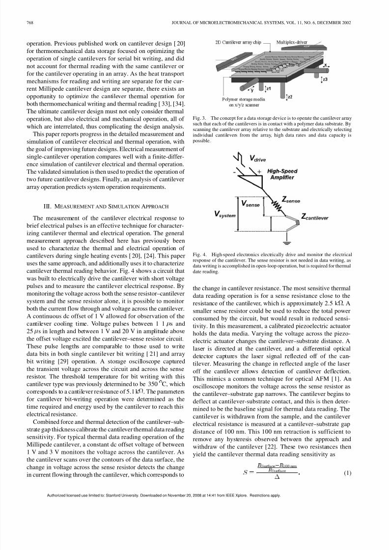
cantilever thermal reading behavior. Fig. 4 shows a circuit that
was built to electrically drive the cantilever with short voltage
pulses and to measure the cantilever electrical response. Bymonitoring the voltage across both the sense resistor–cantilever
system and the sense resistor alone, it is possible to monitor
both the current flow through and voltage across the cantilever.
A continuous dc offset of 1 V allowed for observation of the
cantilever cooling time. Voltage pulses between 1 1 s and
25 s in length and between 1 V and 20 V in amplitude above
the offset voltage excited the cantilever–sense resistor circuit.
These pulse lengths are comparable to those used to write
data bits in both single cantilever bit writing [21] and array
bit writing [29] operation. A storage oscilloscope captured
the transient voltage across the circuit and across the sense
resistor. The threshold temperature for bit writing with this
cantilever type was previously determined to be 350 C, whichcorresponds to a cantilever resistance of 5.1 k . The parameters
for cantilever bit-writing operation were determined as the
time required and energy used by the cantilever to reach this
electrical resistance.
Combined force and thermal detection of the cantilever–sub-
strate gap thickness calibrate the cantilever thermal data reading
sensitivity. For typical thermal data reading operation of the
Millipede cantilever, a constant dc offset voltage of between
1 V and 3 V monitors the voltage across the cantilever. As
the cantilever scans over the contours of the data surface, the
change in voltage across the sense resistor detects the change
in current flowing through the cantilever, which corresponds to
Fig. 3. The concept for a data storage device is to operate the cantilever arraysuch that each of the cantilevers is in contact with a polymer data substrate. Byscanning the cantilever array relative to the substrate and electrically selectingindividual cantilevers from the array, high data rates and data capacity ispossible.
Fig. 4. High-speed electronics electrically drive and monitor the electricalresponse of the cantilever. The sense resistor is not needed in data writing, asdata writing is accomplished in open-loop operation, but is required for thermaldate reading.
the change in cantilever resistance. The most sensitive thermaldata reading operation is for a sense resistance close to the
resistance of the cantilever, which is approximately 2.5 k . A
smaller sense resistor could be used to reduce the total power
consumed by the circuit, but would result in reduced sensi-
tivity. In this measurement, a calibrated piezoelectric actuator
holds the data media. Varying the voltage across the piezo-
electric actuator changes the cantilever–substrate distance. A
laser is directed at the cantilever, and a differential optical
detector captures the laser signal reflected off of the can-
tilever. Measuring the change in reflected angle of the laser
off the cantilever allows detection of cantilever deflection.
This mimics a common technique for optical AFM [1]. An
oscilloscope monitors the voltage across the sense resistor asthe cantilever–substrate gap narrows. The cantilever begins to
deflect at cantilever-substrate contact, and this is then deter-
mined to be the baseline signal for thermal data reading. The
cantilever is withdrawn from the sample, and the cantilever
electrical resistance is measured at a cantilever–substrate gap
distance of 100 nm. This 100 nm retraction is sufficient to
remove any hysteresis observed between the approach and
withdraw of the cantilever [22]. These two resistances then
yield the cantilever thermal data reading sensitivity as
(1)
Authorized licensed use limited to: Stanford University. Downloaded on November 20, 2008 at 14:41 from IEEE Xplore. Restrictions apply.

7/28/2019 AFM - Thermo Mechanical Writing
http://slidepdf.com/reader/full/afm-thermo-mechanical-writing 5/10
KING et al.: AFM CANTILEVERS FOR COMBINED THERMOMECHANICAL WRITING AND THERMAL READING 769
Where is sensitivity in m , is the electrical
resistance of the cantilever in contact with the sample surface
in , and is the cantilever electrical resistance at a
distance of 100 nm from the sample surface in . The absolute
value of can be positive or negative, as the temperature
coefficient of electrical resistance changes sign as the doped
silicon cantilever enters a thermal runaway regime. Chui [35]
provides a detailed study of thermal runaway in doped siliconmicrocantilevers.
A finite-difference simulation predicts the transient cantilever
temperature distribution and electrical properties for the dura-
tion of the electrical heating pulse. The simulation divides the
cantilever and nearby air into finite elements with dimensions of
50 nm on a side. Fig. 5 shows a schematic of the simulation do-
main. By including the presence of the polymer-coated silicon
substrate, the simulation can predict the operation of the can-
tilever during thermal data reading. Solution of the heat equa-
tion calculates the temperature at each of the temperature nodes
at each time step. The heat equation is given as
(2)
Where is the temperature at each temperature node in K,
is the heat generated at each node in W, is the local
thermal conductivity in W/mK, is the material density in
kg/m , is the material heat capacity in J/KgK, and is
time in sec. Equation (2) is solved through a second order
discretization in space. Explicit time advancement employs
steps of 1 ns in length. Circuit design models [36] calculate
the temperature-dependent intrinsic carrier generation and the
temperature-dependent electrical resistivity of the doped silicon
at every time step. The thermal conductivity of the heavily
doped thin silicon cantilever is assumed to be 50 W/mK,and to vary as the inverse of temperature. The simulation
operates in the following manner: for each simulation time
step, the simulation calculates the total cantilever electrical
resistance, which determines the cantilever current at fixed
driving voltage. The cantilever current determines the heating
power at each position along the length of the cantilever. The
simulation agrees with analytical solutions for one-dimensional
transient thermal conduction in the cantilever to within 2%
for the present geometry and simulation parameters. Further
discrepancy between the simulation and measurement results
beyond the simulation error is due to noise and parasitic
capacitance in the cantilever.
IV. CANTILEVER DESIGNS
This work predicts the operation of three separate cantileverdesigns. The first cantilever is identical in its mechanical andelectrical properties to the Millipede cantilever shown in Fig. 1,and it is with this cantilever that measurements are made. Thegood agreement between measurement and simulation verifiesthe simulation predictive ability for operation of the improvedcantilevers. The design of the second cantilever corresponds tothe fastest and most sensitive cantilever that could be made withno changes to the fabrication process that produces the presentMillipede cantilever. Finally, the third cantilever is the fastest
Fig. 5. The finite-difference simulation regime contains temperature nodes inand around the cantilever. The substrate can be added to the simulation as aboundary condition in order to predict cantilever operation during thermal datareading.
and most sensitive that could be produced with CMOS-likemanufacturing processes known today. The present paperrefers to the present cantilever, the improved cantilever, and theadvanced technology cantilever as cantilever Type A, B, and C,respectively. Fig. 6 shows the basic schematics of the presentand proposed cantilevers: Fig. 6(a) represents cantilever TypesA and B, Fig. 6(b) shows Type C. Table I lists the geometric
parameters of heater region area, cantilever length, width,thickness, and cantilever tip height. Table I additionally givesthe electrical and mechanical properties of the three cantilevertypes.
This work assumes that fordata bitwriting in thin poly methylmethacrylate (PMMA) films, the cantilever must reach the pre-viously-reported bit-writing temperature of 350 C [21], [22],[29] and the cantilever tip must be in good contact with thepolymer film. While the overall writing time will be governedalso by loading force and tip shape, the previously publisheddata [21], [22], [29] has shown that a cantilever spring con-stant as high as 3 N/m [21] and as low as 0.01 N/m [21] writesdata bits at a threshold writing temperature of 350 C. In gen-
eral, the cantilevers with the smallest volume in which resistiveheating takes place will be the fastest for heating. The presenceof a thermal constriction near the heater, as in Fig. 6(b), willshorten heating time. Chui [20] designed cantilevers with sim-ilar thermal constrictions, but noted that the longer thermal re-laxation time associated with the thermal constriction adverselyaffectedthe time between serial writing events with a single can-tilever. Increased time between heating events is not necessarilya disadvantage in the design of cantilevers forparallel operation.
The electrical resistance of the cantilever, which is given pri-marily by the electrical resistance of the small heater at thecantilever end, should be as small as possible, to reduce thevoltage and power requirements for device operation. However,
the smallest practical value of the cantilever electrical resistanceisnear1.5 k , asthe resistance ofthe heaterregion mustbe largecompared to the electrical resistance of the cantilever legs andthe on-chip interconnects.
In general the thinnest cantilevers with the shortest tips willbe the most sensitive for thermal data reading [32]. Several gen-erations of Millipede cantilevers have been fabrication, eachthinner than the last. The original Millipede type cantileverswere500 nmthick [27] and had cantilever tips 500 nm in height.The Millipede cantilevers have more recently been made thinnerat 300 nm, and with shorter tips also at 300 nm[29] for improvedreading sensitivity and lower stiffness. The cantilever measuredin the present work is the thinnest we have fabricated to date,
Authorized licensed use limited to: Stanford University. Downloaded on November 20, 2008 at 14:41 from IEEE Xplore. Restrictions apply.

7/28/2019 AFM - Thermo Mechanical Writing
http://slidepdf.com/reader/full/afm-thermo-mechanical-writing 6/10
770 JOURNAL OF MICROELECTROMECHANICAL SYSTEMS, VOL. 11, NO. 6, DECEMBER 2002
(a)
(b)
Fig. 6. Schematic of the basic cantilever “footprint.” Cantilever Type A andType B have the footprint of (a), and cantilever Type C has the footprint of (b).The thermal constrictions reduce the quantity of heat that flows along the legs
of the cantilever, thus increasing writing speed and thermal reading sensitivity.
TABLE IMECHANICAL AND ELECTRICAL DESIGN PARAMETERS OF THE CANTILEVERS
CONSIDERED IN THE PRESENT STUDY
at 200 nm. Shortening the cantilever tips below approximately200 nm will have a reduced improvement on cantilever readingsensitivity, as the mean free path of air molecules at roomtemperature and pressure is near 60 nm [37]. Therefore, at a gapdistance of several mean free path lengths and below, fewer airmolecules will exchange thermal energy with the cantilever and
data substrate, thus reducing the effective thermal conductanceof the air gap below the conductance predicted by continuumtheory [38]. The reduced thermal conductance between thecantilever and the substrate reduces improvements in thermalreading sensitivity accordingly.
The presence of the thermal constriction increases the thermalresistance of the cantilever legs. This increased thermal resis-tance is intended not only to improve the writing speed, butalso to improve thermal reading sensitivity of the cantilever. Thethermal impedance of the thermal constriction causes a higherfraction of the heat generated in the cantilever across the air gap,and into the data substrate below the cantilever. The temperatureof the cantilever heater region therefore depends more strongly
Fig. 7. Time required to reach the bit writing temperature as a function of voltage applied to the cantilever.
upon heat transfer across the air gap, and is more sensitive tochanges in the heat transfer across the air gap.
V. RESULTS AND DISCUSSION
Key parameters that affect the design and operation of a datastorage system are data writing and reading rates, the energyconsumed during data writing, and the sensitivity during datareading. Measurement results for the Type A cantilever com-pare well with predictions made using the finite-difference sim-ulation. Predictions are also made for the operation of the TypeB over its entire operational range and for Type C for a nominaloperation point.
A. Thermomechanical Data Writing
The time required for the cantilever to reach the bit writingtemperature defines a key parameter in the single-cantileverwriting rate. Higher voltages allow the cantilever to reach the bitwriting temperature in shorter time, but can place more stren-uous power supply requirements on the data storage system.The power requirement is particularly important for mobiledata storage applications. Fig. 7 shows the time required forthe cantilever to reach the bit writing temperature as a functionof voltage applied to the cantilever. There exists a threshold
voltage below which the cantilever will never become hotenough to write a data bit. This threshold voltage is measuredas near 6 V for the present cantilever, with improvement to 4 Vfor the Type B cantilever. Bit writing is possible with the typeC cantilever at 2 V at near 1 s heating time. The thresholdwriting voltage defines the longest bit writing time and lowestpower at which the cantilever could operate.
A second parameter which influences systemlevel design andoperation is the energy required to write a single data bit. Thevery small size of the MEMS chip shown in Fig. 2 motivatestargeting an interface with mobile electronics for commercialrealization. Such a mobile device will operate at least some of the time on a battery power supply, for which the energy drawn
Authorized licensed use limited to: Stanford University. Downloaded on November 20, 2008 at 14:41 from IEEE Xplore. Restrictions apply.

7/28/2019 AFM - Thermo Mechanical Writing
http://slidepdf.com/reader/full/afm-thermo-mechanical-writing 7/10

7/28/2019 AFM - Thermo Mechanical Writing
http://slidepdf.com/reader/full/afm-thermo-mechanical-writing 8/10
772 JOURNAL OF MICROELECTROMECHANICAL SYSTEMS, VOL. 11, NO. 6, DECEMBER 2002
Fig. 10. The array operates with multiplexed row-by-row writing and reading[29]. Power is delivered for each row in a serial manner, and each cantileverwill be selected for bit formation by connection of the electrical path along thecolumn. A “1” refers to electrically switching the cantilever “on” for heatingand bit formation; a “0” refers to keeping the cantilever switched “off” for noheating and no bit formation.
Fig. 11. Predictions for array operation of the Millipede Type A cantilever.The data rate can be varied by varying the cantilever driving voltage, which willcorrespond to a change in the power requirement. The circles representoperationof all 1024 cantilevers of the Millipede array shown in Fig. 2.
C. Cantilever Array Operation
Previous published work that focused on improving AFMcantilever design for data storage applications primarily focusedupon serial cantilever writing and reading, and therefore took the single cantilever mechanical, electrical, and thermal timeconstants as the fundamental limits of data rate. Array opera-tion imposes different limits on the data rate. In practice, theMillipede array writes line-by-line, as shown in Fig. 10. A mul-tiplexing scheme selects columns for “1” or “0” to be writtenby pulling up the source of an external transistor, and the rowsare selected one at a time [29]. Thus, in the operation of can-
tilevers in a square by cantilever array, bits can be writtenin the time required to select rows. If rows can be selectedfor at a rate equivalent to the single-cantileverserial writing rate,then bits can be written at the single-cantilever serial writingrate.
The single-cantilever serial writing time is not a fixed numberbut rather a function of heating voltage, as shown in Fig. 7.Therefore, the array data rate will also be a function of heatingvoltage. The practical limit of array operation speeds will not beheating voltage, but heating power. Fig. 11 shows predictions fordata rates possible with the Millipede Type A cantilever in arrayoperation as a function of available heating power. The two linesrepresent two separate operating conditions: one at the lowest
power and speed, the other at a high speed, energy-efficient op-eration point. The cantilever array could operate at any positionbetween the two lines with changes only in the electrical signalsdelivered to the cantilever array. The possibility to dynamicallychange the operation point of a thermomechanical data storagedevice is a feature not previously anticipated, but with possibleadvantages over magnetic data storage devices which must op-
erate at near constant power during write/read operation, due tothe mechanical spinning of the magnetic disk.
VI. SUMMARY AND CONCLUSIONS
This paper reports progress on the design of cantilevers,concurrently optimized for data writing and reading, whichare targeted for use in array operation. Measurements andsimulations are made for the operation of the present generationMillipede cantilever. Good agreement between measurementand simulation indicate progress in the basic understandingof how the cantilever accomplishes data writing and reading.Two additional cantilever designs improve on both the single-cantilever writing time and the thermal data reading sensitivity
over previous cantilever designs. High data rates are possiblewith parallel cantilever operation in an array, and combinedanalysis of single cantilever and array operation shows thesystem-level adaptability in a power and speed tradeoff.
There remain several open opportunities to improve thetechnology discussed in this paper. While the present cantileverarray is square, it is not clear that the best array will be square. Adata storage product requirement could impose power and datarate requirements on that the optimal array is rectangular. Tech-nology applications beyond data storage, such as lithographyor micro-manipulation could drive completely different devicerequirements. The very high thermal data reading sensitivityoffers exciting opportunities for future metrology applications.
ACKNOWLEDGMENT
The authors gratefully acknowledge helpful discussions with
and generous support from P. G. Sverdrup of Intel Corp. C. F.
Quate of Stanford University, and P. F. Seidler and the Micro and
NanoMechanics group of the IBM Zurich Research Laboratory.
REFERENCES
[1] G.Binnig, C. F. Quate,and C. Gerber, “Atomic force microscope,” Phys. Rev. Lett., vol. 56, pp. 930–933, 1986.
[2] R. Luethi, E. Meyer, M. Bammerlin, A. Baratoff, T. Lehmann, L.Howald, C. Gerber, and H.-J. Guentherodt, “Atomic resolution indynamic force microscopy across steps on Si(111)7 2 7,” Zeitschrift
fur Physick B Condensed Matter , vol. 100, pp. 165–167, 1996.[3] A. Majumdar, P. I. Oden, J. P. Carrejo, L. A. Nagahara, J. J. Graham,and J. Alexander, “Nanometer-scale lithography using the atomic forcemicroscope,” Appl. Phys. Lett., vol. 61, pp. 2293–2295, 1992.
[4] S. C. Minnie, H. T. Soh, P. Flueckiger, and C. F. Quate, “Fabricationof 0.1 mm metal oxide semiconductor field-effect transistors with theatomic force microscope,” Appl. Phys. Lett., vol. 66, pp. 703–705, 1995.
[5] M. Heyde, K. Rademan, B. Cappella, M. Greuss, H. Sturm, T.Spangenberg, and H. Niehus, “Dynamic plowing nanolithographyon polymethylmethacrylate using an atomic force microscope,” Rev.Sci. Instrum., vol. 72, pp. 136–141, 2001.
[6] E. B. Cooper, S. R. Manalis, H. Fang, H. Dai, K. Matsumoto, S. C.Minne, T. Hunt, and C. F. Quate, “Terabit-per-square-inch data storagewith the atomic force microscope,” Appl. Phys. Lett., vol. 75, pp.3566–3568, 1999.
[7] H. J. Mamin, R. P. Ried, B. D. Terris, and D. Rugar, “High-density datastorage based on the atomic force microscope,” Proc. IEEE , vol. 87, pp.1014–1027, 1999.
Authorized licensed use limited to: Stanford University. Downloaded on November 20, 2008 at 14:41 from IEEE Xplore. Restrictions apply.

7/28/2019 AFM - Thermo Mechanical Writing
http://slidepdf.com/reader/full/afm-thermo-mechanical-writing 9/10
KING et al.: AFM CANTILEVERS FOR COMBINED THERMOMECHANICAL WRITING AND THERMAL READING 773
[8] P. Vettiger, M. Despont, U. Drechsler, U. Dürig, W. Häberle, M.Lutwyche, H. E. Rothuizen, R. Stutz, R. Widmer, and G. Binnig,“The ‘Millipede’—More than one thousand tips for future AFM datastorage,” IBM Journal of Research and Development , vol. 44, pp.323–340, 2000.
[9] “Avoiding a data crunch: Special industry report on data storage,” Sci. Amer., 2000.
[10] E. Grochowski and R. F. Hoyt, “Future trends in hard disk drives,” IEEE Transactions Magnetics, vol. 32, pp. 1850–1854, 1996.
[11] J. Lohau, A. Moser, C. T. Rettner, M. E. Best, and B. D. Terris, “Writingand reading perpendicular magnetic recording media patterned by a fo-cused ion beam,” Appl. Phys. Lett., vol. 78, pp. 990–992, 2001.
[12] J. J. Ruigrok and M. R. Coehoorn et al., “Disk recording beyond 100Gb/in. : Hybrid recording?,” J. Appl. Phys., vol. 87, pp. 5389–5403,2000.
[13] K.Wilder,C. Quate,D. Adderton,R. Bernstein, andV. Elings,“Noncon-tact nanolithography using the atomic force microscope,” Appl. Phys.
Lett., vol. 73, pp. 2527–2529, 1998.[14] R. D. Piner, J. Zhu, F. Xu, S. Hong, and C. A. Mirkin, “‘Dip-Pen’ nano-
lithography,” Science, vol. 283, pp. 661–663, 1999.[15] Park Scientific ‘Piezolever’ data sheet.[16] IBM Travelstar Disk Drive series data sheet.[17] R. P. Ried, H. J. Mamin, B. D. Terris, L. S. Fan, and D. Rugar,
“6-MHz 2-N/m piezoresistive atomic-force-microscope cantileverswithINCISIVE tips,” J. Microelectromech. Syst., vol. 6, pp. 294–302,1997.
[18] E. M. Chow, H. T. Soh, H. C. Lee, J. D. Adams, S. C. Minne, G.Yaralioglu, A. Atalar, C. F. Quate, and T. W. Kenny, “Integrationof through-wafer interconnects with a two-dimensional cantileverarray,” Sens. Actuators, vol. 83, pp. 118–123, 2000.
[19] E. M.Chow, G. Yaralioglu, C. F. Quate,and T. W. Kenny, “Characteriza-tion of a two-dimensional cantilever array with through-wafer electricalinterconnects,” Applied Physics Letters, submitted for publication.
[20] B. W. Chui, T. D. Stowe, Y. S. Ju, K. E. Goodson, T. W. Kenny, H. J.Mamin, B. D. Terris, and R. P. Ried, “Low-stiffness silicon cantileverwith integrated heaters and piezoresistive sensors for high-density datastorage,” J. Microelectromech. Syst., vol. 7, pp. 69–78, 1998.
[21] G. Binnig, M. Despont, U. Drechsler, W. Häberle, M. Lutwyche, P. Vet-tiger, H. J. Mamin, B. W. Chui, and T. W. Kenny, “Ultrahigh-densityatomic forcemicroscopy data storage with erase capability,” Appl. Phys.
Lett., vol. 76, pp. 1329–1331, 1999.[22] G. Cross, M. Despont, U. Drechsler, U. Dürig, P. Vettiger, W. P. King,
and K. E. Goodson, “Thermomechanical formation and thermal sensingof nanometer-scale indentations in PMMA thin films for parallel and
dense AFM data storage,” J. Mater. Res., to be published.[23] U. Dürig, G. Cross, U. Drechsler, W. Häberle, M. I. Lutwyche, H.
Rothuizen, R. Stutz, R. Widmer, P. Vettiger, G. K. Binnig, W. P. King,and K. E. Goodson, “Millipede—An AFM data storage system at thefrontier of nanotribology,” Tribology Lett., to be published.
[24] H. J. Mamin and D. Rugar, “Thermomechanical writing with an atomicforce microscope tip,” Appl. Phys. Lett., vol. 61, pp. 1003–1005, 1992.
[25] H. J. Mamin, “Thermal writing using a heated atomic force microscopetip,” Applied Physics Letters, vol. 69, pp. 433–435, 1996.
[26] A. Majumdar, “Scanning thermal microscopy,” Annu. Rev. Mater. Sci.,vol. 29, pp. 505–585, 1999.
[27] M. Despont, J. Brugger, U. Drechsler, U. Dürig, W. Häberle, M.Lutwyche, H. E. Rothuizen, R. Stutz, R. Widmer, G. Binnig, and P.Vettiger, “VLSI-NEMS chip for parallel AFM data storage,” Sens.
Actuators, vol. A80, pp. 100–107, 2000.[28] M. Lutwyche, C. Andreoli, G. Binnig, J. Brugger, U. Drechsler, W.
Haberle, H. Rohrer, H. Rothuizen, P. Vettiger, G. Yaralioglu, and C.
Quate, “52
5 AFM cantilever arrays a first step toward a terabit storagedevice,” Sens. Actuators, vol. A73, pp. 89–94, 1999.
[29] M. I. Lutwyche, M. Despont, U. Drechsler, U. Durig, W. Hablerle, H.Rothuizen, R. Stutz, R. Widmer, G. K. Binnig, and P. Vettiger, “Highlyparallel data storage system based on scanning probe arrays,” Appl.Phys. Lett., vol. 77, pp. 3299–3301, 2000.
[30] W. P. King, J. G. Santiago, T. W. Kenny, and K. E. Goodson, “Modelingand simulation of sub-micrometer heat transfer in AFM thermomechan-ical data storage,” ASME MEMS , vol. 1, pp. 583–588, 1999.
[31] W. P. King and K. E. Goodson, “Modeling and simulation of nanometer-scale thermomechanical data bit formation,” in Proc. 2001 ASME Na-tional Heat Transfer Conference, Anaheim, CA, 2001.
[32] M. Asheghi, W. P. King, B. W. Chui, T. W. Kenny, and K. E. Goodson,“Thermal engineering of doped single-crystal silicon microcantileversfor high density data storage,” in Proc. Transducers 1999, the 10th In-ternational Conference on Solid-State Sensors and Actuators, Sendai,Japan, 1999.
[33] W. P. King, T. W. Kenny, K. E. Goodson, G. Cross, M. Despont, U.Duerig, M. Lutwyche, H. Rothuizen, G. Binnig, and P. Vettiger, “Designof AFM cantilevers for combined thermomechanical data writing andreading,” in Proc. Solid State Sensors and Actuators Workshop, HiltonHead, SC, 2000.
[34] W. P. King, T. W. Kenny, K. E. Goodson, G. L. W. Cross, M. Despont,U. Durig, H. Rothuizen, G. Binnig, and P. Vettiger, “Atomic force mi-croscope cantilevers for combined thermomechanical data writing andreading,” Appl. Phys. Lett., vol. 78, pp. 1300–1302, 2001.
[35] B. W. Chui, M. Asheghi, Y. S. Ju, K. E. Goodson, T. W. Kenny, and H. J.Mamin, “Intrinsic-carrier thermal runaway in silicon microcantilevers,” Microscale Thermophys. Eng., vol. 3, pp. 217–228, 1999.
[36] S.M. Sze, Physics of Semiconductor Devices. New York: Wiley, 1981.[37] W. G. Vincenti and C. H. Kruger, Introduction to Physical Gasdy-
namics. New York: Wiley, 1965.[38] W. M. Rohsenow and H. Y. Choi, Heat, Mass, and Momentum
Transfer . Englewood Cliffs, NJ: Prentice-Hall, 1961.
William P. King received the B.S. degree inmechanical engineering from the University of Dayton in 1996 and the M.S. and Ph.D. degrees inmechanical engineering from Stanford University,Stanford, CA, in 1998 and 2002, respectively.
Between 1999 and 2001, he spent 16 months
in the Micro/NanoMechanics Group of the IBMZurich Research Laborartory. In July 2002, he joinedthe faculty of the Woodruff School of MechanicalEngineering at the Georgia Institute of Technology,Atlanta, as Assistant Professor. At Georgia Tech,
his group works on thermal engineering of micro/nanomechanical devices,including thermomechanical data storage and nanoscale thermal processing.
Thomas W. Kenny (M’99) received the B.S. degreein physics from the University of Minnesota, Min-neapolis, in 1983 and the M.S. and Ph.D. degrees inphysics from the University of California, Berkeley,in 1987 and 1989, respectively.
He has worked at the Jet Propulsion Labora-tory, Pasadena, CA, where his research focused
on the development of electron-tunneling-basedmicrosensors and instruments. Since 1994, he hasbeen on the Faculty of the Mechanical EngineeringDepartment, Stanford University, Stanford, CA.
He currently oversees graduate students in the Stanford Microstructures andSensors Laboratory, whose research activities cover a variety of areas such asadvanced tunneling sensors, piezoresistive sensors, cantilever arrays, fracture insilicon, and the mechanical properties of biomolecules, cells, insects, and smallanimals. This group is collaborating with researchers from the IBM Almadenand Zurich Research Centers on nuclear magnetic resonance microscopy andAFM thermomechanical data storage, and with the Bosch RTC on inertialsensors and packaging, and with Intel on fluidic cooling technologies forintegrated circuits.
Kenneth E. Goodson (M’95–A’96) received
the B.S., M.S., and Ph.D. degrees in mechanicalengineering from the Massachusetts Institute of Technology (MIT), Cambridge, in 1989, 1991, and1993, respectively. Currently, he is an AssociateProfessor of Mechanical Engineering at StanfordUniversity, Stanford, CA. Previously, he workedwith the Materials Research Group at DaimlerBenzAG on the thermal design of power circuits.
In 1994, he joined Stanford University, where hisresearch group studies thermal transport phenomena
in electronic micro- and nanostructures. His research has yielded 80 journal andconference papers and four book chapters.
Dr. Goodson has received the ONR Young Investigator Award and the NSFCAREER Award in 1996, Best Paper Awards at SEMI-THERM in 2001, andthe Multilevel Interconnect Symposium in 1998. In 1996, he was a JSPS Vis-iting Professor at the Tokyo Institute of Technology. In 1999, he received theOutstanding Reviewer Award from the ASME Journal of Heat Transfer.
Authorized licensed use limited to: Stanford University. Downloaded on November 20, 2008 at 14:41 from IEEE Xplore. Restrictions apply.

7/28/2019 AFM - Thermo Mechanical Writing
http://slidepdf.com/reader/full/afm-thermo-mechanical-writing 10/10