Affirmative Expert Report Response to Dr. Heywood’s Report ...hydrogengarage.com/pdf/Affirmative...
18
Affirmative Expert Report Response to Dr. Heywood’s Report: “An Assessment of the Fuel Economy Claims Made for the Hydro Assist Fuel Cell (HAFC) System” Jacob Wall Mechanical Engineer August 12, 2010
Transcript of Affirmative Expert Report Response to Dr. Heywood’s Report ...hydrogengarage.com/pdf/Affirmative...

Affirmative Expert Report
Response to Dr. Heywood’s Report:
“An Assessment of the Fuel Economy
Claims Made for the
Hydro Assist Fuel Cell (HAFC) System”
Jacob Wall
Mechanical Engineer
August 12, 2010

2
Table of Contents
1. Background ......................................................................................................................... 4
2. Review of Technical Literature ............................................................................................. 5
Compressed Hydrogen ............................................................................................................5
“Simulating” Electrolysis Products ...........................................................................................5
Experimental Studies Using Electrolysis Products ...................................................................7
Analysis of Electrolysis Products ...........................................................................................11
3. Conclusion ......................................................................................................................... 12
4. References ........................................................................................................................ 15

3
List of Figures
Figure 1: Variation of brake thermal efficiency with electrolysis product percentage. [8] ..............7
Figure 2: Variation of fuel saving with electrolysis product percentage. [8] ..................................8
Figure 3: Variation of engine torque with engine speed. [9] .........................................................9
Figure 4: Variation of specific fuel consumption with engine speed. [9] .......................................9
Figure 5: Hoffman Device for water electrolysis. .......................................................................11
Figure 6: Mass Spectrum Analysis of Electrolysis Products [12] ................................................14
List of Tables
Table 1: Kocaeli University electrolysis system test results. [10] ...............................................10
Table 2: Detailed fuel savings with electrolysis system. [11] ......................................................10
Table 3: Fuel savings with system by engine size. [11] .............................................................10

4
I have personal knowledge of the matters contained in this report and if called as a witness I could, and would, competently testify as to the matters discussed herein.
1. Background My name is Jacob A. Wall. I am currently employed as a Mechanical Engineer for EnergySolutions located in Richland, WA. I completed my Master’s of Science in Biological and Agricultural Engineering from the University of Idaho in 2009. During my Master’s Degree program I researched the production and utilization of biofuels.
As an independent research project, while attending the University of Idaho, I investigated the application of electrolysis products to engines. This project included extensive journal research of the available technical literature related to hydrogen enriched hydrocarbon combustion. The journal research culminated in a journal review paper titled, “Effect of Hydrogen Enriched Hydrocarbon Combustion on Emissions and Performance”. This paper was published, “open-source” on the Panacea University website and consequently mirrored on many other websites. I have recently republished a revised version of this paper for the Conference Proceedings of the 17th Annual NPA Conference. I have presented my research results from this project at the 2008 Alterative Energy and Wellness “Show ‘N Tell” Conference in Ruskin, Florida and the 2009 Alternative Energy Partnership “Show ‘N Tell” Conference in Waldorf, Maryland. These presentations are viewable on my YouTube website (http://www.youtube.com/jakerwall).
My research on the application of electrolysis products to engines led me to investigate the proper design and fabrication techniques for the construction of a common-ducted electrolysis unit. In order to test electrolysis products on an engine, I retrofitted a 50 cc Honda Scooter to operate with a “home-made” electrolysis unit, powered by an auxiliary battery, to supplement its normal gasoline consumption. I operated the scooter with the electrolysis unit installed as my primary form of transportation for an entire summer. With this experimental setup, I observed improved throttle response with the electrolysis unit in operation.
My results from the supplementation of electrolysis products to the scooter engine led me to experiment with running the scooter engine at idle, completely from the output of an electrolysis unit that was powered by an external power supply. The scooter was able to maintain idle at electrical input as low as about 140 Watts. This research project is documented on my YouTube website.
I am continually performing independent research on the properties and application of electrolysis products to engines and burners. Currently, I am researching using electrolysis products to improve combustion in my personal vehicle. Another project I am working on is a validation study to improve the efficiency of a 5 kW Briggs and Stratton Electric Generator using combustion enhancement with electrolysis products. I am actively searching for an opportunity to pursue the research of the combustion of electrolysis products for a PhD dissertation in Mechanical Engineering.
5
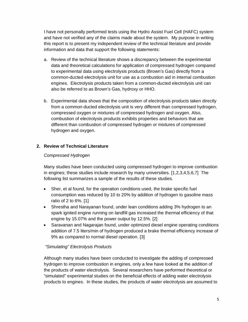
I have not personally performed tests using the Hydro Assist Fuel Cell (HAFC) system and have not verified any of the claims made about the system. My purpose in writing this report is to present my independent review of the technical literature and provide information and data that support the following statements:
a. Review of the technical literature shows a discrepancy between the experimental data and theoretical calculations for application of compressed hydrogen compared to experimental data using electrolysis products (Brown’s Gas) directly from a common-ducted electrolysis unit for use as a combustion aid in internal combustion engines. Electrolysis products taken from a common-ducted electrolysis unit can also be referred to as Brown’s Gas, hydroxy or HHO.
b. Experimental data shows that the composition of electrolysis products taken directly from a common-ducted electrolysis unit is very different than compressed hydrogen, compressed oxygen or mixtures of compressed hydrogen and oxygen. Also, combustion of electrolysis products exhibits properties and behaviors that are different than combustion of compressed hydrogen or mixtures of compressed hydrogen and oxygen.
2. Review of Technical Literature
Compressed Hydrogen
Many studies have been conducted using compressed hydrogen to improve combustion in engines; these studies include research by many universities. [1,2,3,4,5,6,7] The following list summarizes a sample of the results of these studies.
• Sher, et al found, for the operation conditions used, the brake specific fuel consumption was reduced by 10 to 20% by addition of hydrogen to gasoline mass ratio of 2 to 6%. [1]
• Shrestha and Narayanan found, under lean conditions adding 3% hydrogen to an spark ignited engine running on landfill gas increased the thermal efficiency of that engine by 15.07% and the power output by 12.5%. [2]
• Saravanan and Nagarajan found, under optimized diesel engine operating conditions addition of 7.5 liters/min of hydrogen produced a brake thermal efficiency increase of 9% as compared to normal diesel operation. [3]
“Simulating” Electrolysis Products
Although many studies have been conducted to investigate the adding of compressed hydrogen to improve combustion in engines, only a few have looked at the addition of the products of water electrolysis. Several researchers have performed theoretical or “simulated” experimental studies on the beneficial effects of adding water electrolysis products to engines. In these studies, the products of water electrolysis are assumed to

6
be a 2 to 1 ratio of diatomic hydrogen and diatomic oxygen, excluding any radicals contained in the electrolysis products. [4,5,6,7]
Shrestha and Karim have conducted extensive research into engine performance and operating parameters. From this research, they developed an experimental model to predict engine performance for varying operating conditions. In the paper, “Hydrogen as an additive to methane for spark engine applications” the experimental model was used to predict the performance of a methane fueled engine enhanced with hydrogen and hydrogen/oxygen mixtures. This model data was compared to the efficiency of a standard electrolysis based hydrogen generating process. From this comparison, it was determined that no significant engine performance improvement could be realized when the energy to produce the hydrogen was taken from the engine system. [4]
Henshaw et al. have published several papers investigating the effects of adding electrolysis products on hydrocarbon combustion. In the paper titled, “Effects of addition of electrolysis products on methane/air premixed laminar combustion” the CHEMKIN simulation software was used to determine the effects of adding electrolysis products to combustion. It was found that 10% and 20% hydrogen addition improved the lean flammability limit, of the air/fuel mixture, by 2% whereas 10% hydrogen/oxygen improved the lean flammability limit by 5%. The addition of 10% hydrogen/oxygen improved the flame speed by the same amount as the addition of 20% hydrogen. [6]
In the papers, “The addition of hydrogen to a gasoline-fuelled SI engine” and “Investigating combustion enhancement and emissions reduction with the addition of 2H2 + O2 to an SI engine, experimental studies were conducted to determine the effect of “simulated” electrolysis products compared to compressed hydrogen for combustion enhancement in an internal combustion engine. In order to prepare the “simulated” electrolysis products test mixture, a tank was filled with 97% air, 2% H2 and 1% O2. This mixture was used as the air intake for the test engine for the “simulated” electrolysis product enhancement experiments. The hydrogen test mixture was prepared by filling a tank with 98% air and 2% H2. This mixture was used as the air intake for the test engine in the hydrogen enhancement experiments. The test mixtures were prepared in this manner to insure the mixtures were below the flammability limit of hydrogen in air.
These studies provided experimental data for the enhancement of the gasoline fuel with mixtures of hydrogen and “simulated” electrolysis products. The results were compared to the baseline engine operation. The resulting performance increase of the enhanced engine was compared to the output and efficiency of a commercially available electrolysis unit. From this comparison, it was found that the performance increase of the hydrogen and “simulated” electrolysis product enhancement would not make up for the energy cost of the electrolysis process. The results were presented with the caveat that optimization of the engine’s spark timing and use of actual electrolysis products could improve the outcome. [5,7]

7
Experimental Studies Using Electrolysis Products
There are several research studies that have been conducted using electrolysis products taken directly from an electrolysis unit. Two studies were conducted using a diesel generator supplemented with electrolysis products. [8,9] Studies have also been conducted, to determine the effects on automobile engine performance of adding electrolysis products produced on-board using power from the vehicle’s alternator. [10,11] These studies found performance increases even when the power required by the electrolysis process is taken from the engine system. The results of these studies are quite different than the results of the “simulated” electrolysis products studies.
In the paper titled, “Effect of H2/O2 addition in increasing the thermal efficiency of a diesel engine”, electrolysis products that were produced directly from a commercial water electrolysis welding unit were added to a 4 liter diesel engine. The engine was operated under constant speed and the load. The amount of electrolysis products added to the engine was varied to determine their effect on engine efficiency and performance. Although the electrolysis unit was powered from an external power supply, the power needed to produce the electrolysis products was included as an energy input in the engine’s thermal efficiency calculation. This study found that increases in thermal efficiency and decreases in fuel consumption could be obtained. Figure 1 and 2 provide a summary of the results of this study. Figure 1 shows the effect of the addition of electrolysis products, in percentage of total diesel equivalent, on brake thermal efficiency. Figure 2 shows the effect of the addition of electrolysis products, in percentage of total diesel equivalent, on percentage of fuel savings. From these figures it can be seen that, for this experimental setup, increasing the percentage of electrolysis products increased the thermal efficiency and the fuel savings. [8]
Figure 1: Variation of brake thermal efficiency with electrolysis product percentage. [8]

8
Figure 2: Variation of fuel saving with electrolysis product percentage. [8]
In the paper, “Effect of hydroxy (HHO) gas addition on performance and exhaust emissions in compression ignition engines, electrolysis products were produced by a small common-ducted electrolysis unit powered by the engine system and added to the engine to increase thermal efficiency, fuel efficiency and decrease emissions. The test engine was a 4 liter direct-injection diesel. A dynamometer was connected to the engine, which adjusted the load to maintain a constant engine speed. The engine speed, power output, specific fuel consumption and emissions were recorded using a data logger. Each test run was performed in triplicate and the results averaged to improve accuracy.
An electronic control system was developed to vary the energy input applied to the electrolysis system based on engine speed. It was found that when a constant flow rate of electrolysis products was added to the engine, without the control system, the results were less favorable than the control case. The electrolysis system was supplied with 120 watts at engine speeds above 1750 rpm and 50 watts below 1750 rpm. This study found that the engine, using combustion enhancement by the electrolysis system, produced an average of 19.1% increase in torque compared to normal diesel operation. It was also found that an average decrease of 14% in specific fuel consumption was achieved compared to normal diesel operation. Figure 3 shows the effect of the electrolysis system on engine torque over the range of engine speed. Figure 4 shows the effect of the electrolysis system on specific fuel consumption. From these figures it can be seen that torque is greater and the fuel consumption is reduced with the electrolysis system in operation compared to normal diesel operation. [9]

9
Figure 3: Variation of engine torque with engine speed. [9]
Figure 4: Variation of specific fuel consumption with engine speed. [9]
In the paper, “Fuel economy improvement by on board electrolytic hydrogen production”, an on-board electrolysis system powered by the automobile’s alternator, was tested on four vehicles. The system was evaluated to determine it’s effect on fuel consumption. Driving tests were conducted under city traffic conditions. Table 1 shows the average increase in fuel economy for the vehicles tested. This table shows that fuel economy increases ranging from 26.3% to 42.9% were obtained. [10]

10
Table 1: Kocaeli University electrolysis system test results. [10]
In the paper, “A field study of the effects of the hydrogen generating system on power, fuel economy and emissions in gasoline and diesel engines”, real world fuel economy data was collect and analyzed for a commercial electrolysis system. This study analyzed 33 fuel economy logs obtained by customers of the system. Table 2 shows detailed logs of two vehicles comparing baseline fuel economy data to the fuel economy obtained using the electrolysis system. From this table it can be seen that, for these two vehicles, significant fuel savings were obtained. Table 3 shows the averaged fuel savings for the 33 vehicles. This table shows that fuel savings could be obtained for a wide range of vehicles. The average fuel savings, across the range of vehicles, was 20.0%. [11]
Table 2: Detailed fuel savings with electrolysis system. [11]
Table 3: Fuel savings with system by engine size. [11]
The manufacturer of the electrolysis system used in this study, is currently marketing an updated system under the trade name “Hy-drive”. According to the company’s website, the system is being marketed for fuel economy and emissions improvement on CAT diesel engines. Tests are claimed to have been conducted by an independent third
Kocaeli University Electrolysis test results
Vehicle % Increase Fuel Economy
1993 Volvo 940 42.9%
1996 Mercedes 280 36.4%
1992 Fiat Kartal 26.3%
1992 Fiat Dogan 33.3%
Detailed Fuel Savings1994 Ford Bronco. V8. 5.0L Engine
# Fills MPG L/100 kmBaseline 7 14.7 19.5W/ System 14 22.6 12.8% Fuel Savings 53.7 34.31998 Volvo VN Diesel 12.7L Engine
# Fills MPG L/100 kmBaseline 3 6.2 46W/ System 13 7.35 38.4% Fuel Savings 18.5 15.6
Fuel savings by engine size# of
VehiclesEngine Size (L)
Model Years
Savings
(%)
Deviation
(%)7 1.8-3.3 1984-1995 20.7% 4.1%6 3.4-4.3 1974-1997 20.8% 15.6%8 5.0-5.2 1986-1996 24.9% 8.5%4 5.6-5.9 1992,1996 12.4% 8.7%3 7.3,7.5 1995,1996 24.0% 6.8%5 12.0,12.7 1995-1998 13.4% 1.8%
33 1.8-12.7 1974-1998 20.0% 9.2%

11
party, following the TMC/SAE J1321 test protocols. The system is claimed to provide an overall average fuel savings of 10.47% (http://www.hy-drive.com/).
Analysis of Electrolysis Products
A typical water electrolysis unit produces hydrogen at the cathode electrode and oxygen at the anode electrode. A barrier is used to separate the two gases, allowing them to be collected separately. The simplest example of this type of electrolysis system is the Hoffman device (See figure 5). The water electrolysis units typically used for generation of electrolysis products for combustion enhancement of engines do not have a barrier separating the gases coming from the electrodes. The entire mixture of gases produced from a water electrolysis unit that is specifically designed to electrolyze water and not separate the gases coming from the unit are often referred to as Brown Gas, HHO or Hydroxy.
Figure 5: Hoffman Device for water electrolysis.
Electrolysis products, from a common-ducted electrolysis unit, have been shown to exhibit very unique properties. One property of the combustion of the electrolysis products is the ability to produce a different flame temperature at point of contact depending on the target material. [12,13] The gases have been shown to have the ability to weld metals and ceramics with very high melting temperatures, such as tungsten. Research has shown that the burning temperature of electrolysis products can produce temperature as high as 6000°C while normal hydrogen is only 2700°C. [13,14,15] Currently, research is being conducted in Korea for using a burner, fueled by electrolysis products, for the vitrification of solid waste incinerator ashes. [16]
Several researchers have conducted mass spectrum analysis of the products of common-ducted electrolysis units. These experiments show that electrolysis products contain many components that are different than what would be expected from mixture containing normal compressed hydrogen and oxygen. [12,13]
Research conducted by Dr. Santilli, has found that the molecular weight of common-ducted electrolysis products is greater than what would be expected from a mixture of hydrogen and oxygen gases at a 2 to 1 ratio. Gas Chromatographer data also shows several components in the gases that are unique, including normal hydrogen, normal

12
oxygen, atomic hydrogen, atomic oxygen, radicals of OH and HO, and several unexpected new species of molecules. [13]
Student researcher Chris Eckman has successfully replicated Dr. Santilli’s analysis of common-ducted electrolysis products. Mass Spectrum analysis conducted at Idaho State University shows that the mixture of gases contains similar components to Dr. Santilli’s results. Figure 6 shows a mass analysis of electrolysis products from a common-ducted electrolysis unit. This data was taken using a Tandem Mass Spectrometry (MS/MS) with an accuracy of 5% standard deviation. This analysis has led to a research study being conducted, by a research group at MIT, to find cutting edge, new applications for this very unique gas. [12]
3. Conclusion
1. Introduction of compressed hydrogen gas into the intake of an internal combustion engine can improve the efficiency and performance of that engine.
2. Performing theoretical and experimental studies attempting to “simulate” electrolysis products from a common-ducted electrolysis show that using the engine output to power the electrolysis process should not lead to an overall increase in efficiency of the system.
3. Experimental studies using electrolysis products (Brown’s Gas) taken directly from a common-ducted electrolysis unit to improve the efficiency of the engine system, suggest that efficiency gain can be obtained even when the electrolysis is powered from the engine system. The results of these studies show that an average increase of 20% in fuel economy can be obtained over a wide range of engines. Individual engines were able to achieve much greater results. This suggests that there is a significant difference between compressed hydrogen, mixtures of compressed hydrogen and oxygen at a 2 to 1 ratio and electrolysis products (Brown’s Gas) taken directly from a common-ducted electrolysis unit.
4. Analysis of common-ducted electrolysis products show that the mixture contains
components that are unique and very different from what would be expected from a 2 to 1 ratio of compressed hydrogen and oxygen.
5. Research investigating the properties and applications of electrolysis products from a common-ducted electrolysis unit is greatly lacking in the technical literature. Further research should be conducted before discounted the results that could be obtained from adding common-ducted electrolysis products (Brown’s Gas) to internal combustion engine systems.

___________________________________~___________________ J
A copy of my professional resume is attached.
I declare under penalty of perjury that the contents of my report are true and correct.
Executed: August 12, 2010 (J~ Jacob A. Wall
Jo.
13

14
Figure 6: Mass Spectrum Analysis of Electrolysis Products [12]

15
4. References [1] Y. Hacohen and E. Sher, “An internal combustion SI engine fueled with hydrogen-
enriched gasoline”, Israel Journal of Technology 25:41-54 (1989) [2] B. Shrestha and Narayanan, “Landfill gas with hydrogen addition – A fuel for SI
engines”, Fuel 87:3616-3626 (2008). [3] N. Saravanan and G. Nagarajan, “An experimental investigation on optimized manifold
injection in a direct-injection diesel engine with various hydrogen flowrates”, Proc Inst Mech Eng D J Auto Eng. 2007;221:1575-84.
[4] B. Shrestha and G.A. Karim, “Hydrogen as an additive to methane for spark ignition
engine applications”, Int J Hydrogen Energy 24:577-586 (1999).
[5] T. Andrea et al, “The Addition of Hydrogen to a Gasoline-Fuelled SI Engine”, Int J Hydrogen Energy 29:1541-1552 (2004).
[6] C. Uykur et al, “Effects of Addition of Electrolysis Products on Methane/Air Premixed Laminar Combustion”, Int J Hydrogen Energy 26:265-273 (2001).
[7] T. Andrea et al, “Investigating Combustion Enhancement and Emissions Reduction with the Addition of 2H2 + O2 to a SI Engine”, SAE Paper, 2003320011 (2003).
[8] S. Bari and M.M. Esmaeil, “Effect of H2/O2 addition in increasing the thermal efficiency of
a diesel engine”, Fuel 89:378-383 (2010). [9] Ali Can Yilmaz, et al., “Effect of hydroxy (HHO) gas addition on performance and
exhaust emissions in compression ignited engines”, Int J Hydrogen Energy (2010), doi:10.1016/j.ijhydene.2010.07.040
[10] Z. Dulger and K. Ozcelik, “Fuel Economy Improvement by on Board Electrolytic Hydrogen Production”, Int J Hydrogen Energy 25:895-897 (2000).
[11] G. Balan, “Field study of the effects of the hydrogen generating system on power, fuel
economy and emissions in gasoline and diesel engines”, Proceedings of the 1999 Spring Technical Conference of the ASME Internal Combustion Engine Division, Columbus, IN, Paper No. 99-ICE-178.
[12] C. Eckman, “Plasma Orbital Expansion of the Electrons in Water”, Proceedings of the
17th Annual Natural Philosophy Alliance Conference, Long Beach, CA, Vol. 6, No. 2. [13] R. Santilli, “A new gaseous and combustible form of water”, Int J Hydrogen Energy
31:1113-1128 (2006).

16
[14] O. Hung-Kuk, “Some comments on implosion and Brown gas”, J Materials Processing Tech 95:8-9 (1999).
[15] H. Ymamoto, “Explanation of anomalous combustion of Brown’s Gas using Dr. Mills’
Hydrino Theory ”, SAE Paper, 1999-01-3325 (1999). [16] Park et al, “Vitrification of Municipal Solid Waste Incinerator Fly ash using Brown’s Gas”,
Energy & Fuels 19:258-262 (2005).
J AC OB W AL L 3324 West 10th Ave • Kennewick, WA 99336 • [email protected] • (208) 596-0952
E NG I NE E R I NG PR OF E SSI ONA L
SUM M AR Y OF QUAL I FI C A T I ONS
• Passionate about projects, particularly those related to alternative energy. Able to see the big picture when faced with a problem and able to find the best solution.
• Always seeking new ways to improve a process. Forward thinker, see possibilities of what could be. • Effectively able to communicate complicated concepts in an understandable manner. • Maximize resources to achieve customer satisfaction and increased productivity, meet deadlines and goals. Implement
and coordinate both strategic and tactical plans to enhance performance. • Adept and experienced in problem solving and providing solutions. Excellent qualifications in leadership and
interpersonal communications. Persuasive, with ability to communicate effectively with culturally diverse audience. • Extensive research both privately and academically in biofuels and bioenergy. • Public speaking and executive management briefing experience. • Computer skills include MS Office Suite, AutoCAD, Pro/Engineer, SolidWorks, MSC Nastran, MatLab, Ansys,
LabView, NASA CEA, Cyberlink PowerDirector, Computer Hardware, Wireless and Ethernet Networking.
PR O FE SSI ONAL E X PE R I E NC E
M E C H ANI C AL E NG I NE E R February 2010 – Present ENERGYSOLUTIONS Richland, WA • Designed mechanical assemblies for the U-233 Material Downblending and Disposition Project at Oak Ridge National
Laboratory. • Incorporated information from process piping models and collaborated with Mechanical Designers to prepare
engineering drawings. • Performed checking and accuracy verification on engineering drawings and worked with Mechanical Designers to
make corrections. • Prepared and verified accuracy of Equipment Specification. • Integrated information from mechanical and P&ID drawings into equipment lists and datasheets. M E C H ANI C AL T E ST E NG I NE E R October 2009 – February 2010 MID COLUMBIA ENGINEERING, INC. Richland, WA • Conducted functional and fabrication acceptance testing operations on assemblies and components for the Hanford
Tank Waste Treatment and Immobilization Plant Autosampling System. • Performed troubleshooting on mechanical assemblies and components to bring them into compliance with test criteria. • Prepared testing procedures and reports and earned NQA-1 Certification of Qualification. • Interpreted information from mechanical, electrical and P&ID drawings to facilitate testing operations. • Managed test procedure prerequisite activities to ensure completion of testing operations. R E SE AR C H ASSI ST ANT August 2007 – August 2009 UNIVERSITY OF IDAHO Moscow, ID • Designed and realized the experimental equipment and developed the protocols for biodiesel purification testing. • Characterized biodiesel purification products to determine performance and cost effectiveness. • Gained extensive experience using chemical analytical equipment for the analysis and characterization of fuels. • Conducted studies on the production and utilization of biodiesel as an alternative diesel fuel using the 500 gallon
University of Idaho pilot plant. Developed a feedback mechanism for improved pump control. • Supervised student interns in the Biofuels Research Laboratory in conducting research projects including operating lab
equipment and ensuring lab safety. Developed and delivered presentations of study results for clients and at technical conferences. Served as a lab assistant for two years during an annual two week biodiesel technology workshop. Represented university BAE Department at 2008 Ag Expo in Spokane, Washington. Gave presentation to high school students on production of biodiesel.

JACOB WALL ● [email protected] ● (208) 596-0952 ● Page 2
E NG I NE E R I NG I NT E R N November 2003 – January 2007 CASCADE ENERGY ENGINEERING Walla Walla, WA • Entered and formatted refrigeration and compressed air systems data such as equipment set points into computer
models to perform energy usage calculations. • Assisted engineers on energy studies of industrial facilities; participated in site visits to obtain information on baseline
energy usage in order to make effective energy efficiency recommendations based on payback time vs. energy savings. • Communicated with equipment vendors to obtain energy usage data on refrigeration equipment.
E DUC AT I ON AND T R AI NI NG
M AST E R OF SC I E NC E I N B I OE NE R G Y /B I OF UE L S 2009 UNIVERSITY OF IDAHO Moscow, ID Master’s Thesis: Evaluation of Methods for the Purification of Biodiesel; GPA 3.4/4.0
B AC H E L OR OF SC I E NC E I N E NG I NE E R I NG 2007 WALLA WALLA UNIVERSITY College Place, WA Concentration in Mechanical Engineering; Fundamentals of Engineering Exam Certificate; GPA 3.1/4.0 Relevant Coursework
• Thermodynamics, Instrumentation, Electric Power/Controls, Internal Combustion Engine Design, Combustion/Air Pollution, Advanced CAD/MCAE, Electromechanical Energy Conversion, Heat Transfer, Biofuels/Bioenergy, HVAC Design, Small Engines, Materials, Manufacturing Systems, Machine Design, Mechanics of Flight
Professional Development
• Cascade Energy Engineering Industrial Energy Efficiency Workshop, University of Idaho Biodiesel Technology Workshop, NQA-1 Certification of Qualification, Earned private pilot license.
E QUI PM E NT SK I L L S
• Gas Chromatograph, Auto Titrator, Karl Fisher, Calorimeter, Cold/Pour Point apparatus, Ultra-low Sulfur Analyzer, Engine Emission Analyzer, Engine Dynamometer, Air/Fuel Ratio Logger, Micro Data Logger, Fuel controller/ECU, Oxygen Sensor, Electrical Measurement devices, table saw, drill press, metal shear, arc welder.
PUB L I C AT I ONS
• “Soap and Glycerin Removal from Biodiesel using Waterless Processes”, ASABE Transactions Journal • “Soap Removal by Waterless Wash Methods”, Conference Paper, 2008 ASABE Annual Meeting, Providence, Rhode Island. • “Effect of Hydrogen Enriched Hydrocarbon Combustion Emissions and Performance”, Conference Paper, 17th Annual NPA
Conference at Cal State Long Beach.
R E SE AR C H
Master Thesis: Evaluation of Methods for the Purification of Biodiesel • Investigated the performance of ion exchange resins and solid adsorbents for purifying biodiesel and developed a theory
outlining the modes involved. • Developed presentations detailing research results for the Thermax Company. • Designed models of electrolysis units and fabricated prototypes. Retrofitted Toyota Camry to operate with hydrogen as a
combustion aid. Modified and tested a Honda engine to operate on hydrogen as a supplemental or standalone fuel. Developed YouTube website to document research results. (www.YouTube.com/jakerwall)
• Presented at the 2008 Alterative Energy and Wellness “Show ‘N Tell” Conference in Ruskin, Florida and the 2009 Alternative Energy Partnership “Show ‘N Tell” Conference in Waldorf, Maryland.
AF FI L I AT I ONS AND AW AR DS
• EIT Certificate; National Honor Society; graduated with Honors from Muscatine High School


![Affirmative Action Report-15th January 2010[1]_1](https://static.fdocuments.net/doc/165x107/553cb13f55034642438b48ec/affirmative-action-report-15th-january-201011.jpg)