AES•FireTap Model 7770 · PDF fileThe FireTap is an accessory for the AES models...
58
Rev 1.5b 1 January 2010 AES•FireTap Model 7770 Supplemental Alarm Reporting Device FireTap Installation and Operation Manual AES Corporation 285 Newbury Street. Peabody, Massachusetts 01960-1315 USA Tel: USA (978) 535-7310. Fax: USA (978) 535-7313 Copyright 2006/2010, All rights Reserved
Transcript of AES•FireTap Model 7770 · PDF fileThe FireTap is an accessory for the AES models...

Rev 1.5b 1 January 2010
AES•FireTap Model 7770
Supplemental Alarm Reporting Device
FireTap Installation
and Operation Manual
AES Corporation
285 Newbury Street. Peabody, Massachusetts 01960-1315 USA
Tel: USA (978) 535-7310. Fax: USA (978) 535-7313
Copyright 2006/2010, All rights Reserved

Rev 1.5b 2 January 2010
AES•FireTap™ 7770
FireTap Installation & Operation Manual
1. SUMMARY .......................................................................................................................................................5
2. COMPATIBILITY AND COMPLIANCE ..................................................................................................................5
2.1 RADIO NETWORK COMPATIBILITY ........................................................................................................................... 5 2.1.1 Remote.................................................................................................................................................... 5 2.1.2 Central .................................................................................................................................................... 5
2.2 FACP COMPATIBILITY (SUPPORTED PANELS) ............................................................................................................. 6 2.2.1 Notifier ONYX Series................................................................................................................................ 6 2.2.2 GAMEWELL Identiflex IF600 SERIES ........................................................................................................ 6 2.2.3 FIRE-LITE MS-9200 .................................................................................................................................. 6 2.2.4 SILENT KNIGHT using the 5824 Serial Port module................................................................................. 6 2.2.5 GE Est-i .................................................................................................................................................... 6 2.2.6 GE vigilant............................................................................................................................................... 6 2.2.7 Siemens MXL........................................................................................................................................... 6 2.2.8 FCI-7100 .................................................................................................................................................. 6
2.3 UL COMPLIANCE NOTES ....................................................................................................................................... 6
3. INSTALLING THE FIRETAP ON THE SUBSCRIBER UNIT .......................................................................................7
4. LED INDICATORS PATTERNS .............................................................................................................................8
5. OVERVIEW .......................................................................................................................................................9
6. CONNECTING THE FIRETAP TO THE FACP........................................................................................................10
6.1 SERIAL DATA CONNECTIONS ................................................................................................................................ 10
7. CONTACT-ID EXPLAINED.................................................................................................................................10
7.1 CONTACT-ID EVENT CODES ................................................................................................................................. 11
8. PANEL SPECIFIC SETUP ...................................................................................................................................12
8.1 NOTIFIER ONYX SERIES ...................................................................................................................................... 12 8.1.1 Fire panel connection to 7770............................................................................................................... 12 8.1.2 Connection supervision ......................................................................................................................... 12 8.1.3 Fire panel programming ....................................................................................................................... 13 8.1.4 7770 FireTap JP1, FACP Selection Jumpers ........................................................................................... 13 8.1.5 Notifier to Ademco CID Translations..................................................................................................... 13 8.1.6 Examples of CID translations ................................................................................................................ 14 8.1.7 Examples of events and automation messages .................................................................................... 14
8.1.7.1 Duct smoke on Loop1, detector 75 .................................................................................................................... 14 8.1.7.2 Pull Station Loop1 Module 12 ............................................................................................................................ 15 8.1.7.3 Monitor Module: Loop1 Module 100 - tamper.................................................................................................. 15 8.1.7.4 Monitor Module Loop1 Module 80 - fire Alarm................................................................................................. 16 8.1.7.5 Smoke Detector Loop1 Detctor 10..................................................................................................................... 16

Rev 1.5b 3 January 2010
8.1.7.6 Heat Detector: Loop1 detector 60 ..................................................................................................................... 17 8.2 GAMEWELL IDENTIFLEX IF600 SERIES .............................................................................................................. 18
8.2.1 Fire Panel connection............................................................................................................................ 18 8.2.2 Connection supervision ......................................................................................................................... 18 8.2.3 Fire Panel programming ....................................................................................................................... 18 8.2.4 7770 FireTap JP1, FACP Selection Jumpers ........................................................................................... 19 8.2.5 Gamewell to Ademco CID Translations................................................................................................ 19 8.2.6 Examples of CID translations ................................................................................................................ 19 8.2.7 Examples of events and automation messages .................................................................................... 20
8.2.7.1 Pull Station Circuit 1 Device 3 ............................................................................................................................ 20 8.2.7.2 Smoke Detector Circuit 1 Device 4..................................................................................................................... 21
8.3 FIRE-LITE MS-9200 ........................................................................................................................................ 22 8.3.1 Fire Panel connection............................................................................................................................ 22 8.3.2 Connection supervision ......................................................................................................................... 22 8.3.3 Fire Panel programming ....................................................................................................................... 23 8.3.4 7770 FireTap JP1, FACP Selection Jumpers ........................................................................................... 23 8.3.5 Firelite to Ademco CID Translations...................................................................................................... 23 8.3.6 Examples of CID translations ................................................................................................................ 23 8.3.7 Examples of events and automation messages .................................................................................... 24
8.3.7.1 Pull Station Loop1 Module 01 ............................................................................................................................ 24 8.3.7.2 Smoke Detector Loop1 Detector 02................................................................................................................... 25 8.3.7.3 Heat Detector Loop1 Detector 01...................................................................................................................... 26
8.4 SILENT KNIGHT USING THE 5824 SERIAL PORT MODULE ....................................................................................... 27 8.4.1 Fire Panel connection............................................................................................................................ 27 8.4.2 Connection supervision ......................................................................................................................... 28 8.4.3 Fire Panel programming ....................................................................................................................... 28 8.4.4 7770 FireTap JP1, FACP Selection Jumpers ........................................................................................... 28 8.4.5 Silent Knight to Ademco CID Translations............................................................................................. 29 8.4.6 Examples of CID translations ................................................................................................................ 29 8.4.7 Examples of events and automation messages .................................................................................... 30
8.4.7.1 Monitor Module 33 Device 01 ........................................................................................................................... 30 8.4.7.2 Smoke Detector Module33 Device 02............................................................................................................... 31 8.4.7.3 Pull Station Module33 Dev 01............................................................................................................................ 31
8.5 GE EST-I.......................................................................................................................................................... 32 8.5.1 Fire Panel connection............................................................................................................................ 32 8.5.2 Connection supervision ......................................................................................................................... 32 8.5.3 Fire Panel programming ....................................................................................................................... 32 8.5.4 7770 FireTap JP1, FACP Selection Jumpers ........................................................................................... 33 8.5.5 EST to Ademco CID Translations ........................................................................................................... 33 8.5.6 Examples of CID translations ................................................................................................................ 33 8.5.7 Examples of events and automation messages .................................................................................... 34
8.5.7.1 Smoke detector on Loop1 as Device 02 ............................................................................................................. 34 8.5.7.2 Heat Detector Loop1 Device 01 ......................................................................................................................... 35 8.5.7.3 Pull Station Loop1 Device 03.............................................................................................................................. 35
8.6 GE VIGILANT..................................................................................................................................................... 36 8.6.1 Fire Panel connection............................................................................................................................ 36 8.6.2 Connection supervision ......................................................................................................................... 36 8.6.3 Fire Panel programming ....................................................................................................................... 36 8.6.4 7770 FireTap JP1, FACP Selection Jumpers ........................................................................................... 37 8.6.5 GE Vigilant to Ademco CID Translations ............................................................................................... 37 8.6.6 Examples of CID translations ................................................................................................................ 37 8.6.7 Examples of events and automation messages .................................................................................... 38
8.6.7.1 Smoke Detector Loop1 Dev 01........................................................................................................................... 38 8.6.7.2 Horn Strobe Trouble Dev126 ............................................................................................................................. 39 8.6.7.3 Heat Detector Loop1 Dev 127............................................................................................................................ 39 8.6.7.4 Pull Station Loop1 Dev 126 ................................................................................................................................ 40
Rev 1.5b 4 January 2010
8.6.7.5 Monitor Module Loop1 Dev 249........................................................................................................................ 40 8.6.7.6 Monitor Module Tamper Loop1 Dev 249.......................................................................................................... 41
8.7 SIEMENS MXL .................................................................................................................................................. 42 8.7.1 Fire Panel connection............................................................................................................................ 42 8.7.2 Connection supervision ......................................................................................................................... 42 8.7.3 Fire Panel programming ....................................................................................................................... 43 8.7.4 7770 FireTap JP1, FACP Selection Jumpers ........................................................................................... 43 8.7.5 Siemens MXL to Ademco CID Translations............................................................................................ 43 8.7.6 Examples............................................................................................................................................... 43 8.7.7 Examples of events and automation messages .................................................................................... 44
8.7.7.1 Monitor module tamper, Loop1 Device 14 ........................................................................................................ 44 8.7.7.2 Monitor module WaterFlow Loop1 Device 13 .................................................................................................. 45 8.7.7.3 Heat Detector Loop1 Dev 11 ............................................................................................................................. 46 8.7.7.4 Smoke Detector Loop1 Dev 10.......................................................................................................................... 47 8.7.7.5 Pull Station Loop1 Dev 12 .................................................................................................................................. 48
8.8 FCI-7100........................................................................................................................................................ 49 8.8.1 Fire Panel connection............................................................................................................................ 49 8.8.2 Connection supervision ......................................................................................................................... 49 8.8.3 Fire Panel programming ....................................................................................................................... 49 8.8.4 7770 FireTap JP1, FACP Selection Jumpers ........................................................................................... 50 8.8.5 FCI to Ademco CID Translations ............................................................................................................ 50 8.8.6 Examples............................................................................................................................................... 50 8.8.7 Examples of events and automation messages .................................................................................... 51
8.8.7.1 Pull Station 1 on Loop 1 ..................................................................................................................................... 51 8.8.7.2 Smoke Detector Loop1 Sensor 1 ........................................................................................................................ 52 8.8.7.3 Smoke Detector Loop1 Sensor 2 ........................................................................................................................ 52 8.8.7.4 Pull Station 4 on Loop 1 ..................................................................................................................................... 53 8.8.7.5 Pull Station 30 on Loop 1 ................................................................................................................................... 53
9. BUILT-IN TESTS OF THE 7770 ..........................................................................................................................54
9.1 REQUIRED MATERIAL .......................................................................................................................................... 54 9.2 TEST CABLE CONSTRUNCTION ............................................................................................................................... 54 9.3 ACTIVATING THE BUILT-IN TEST MODE .................................................................................................................... 54 9.4 FUNCTIONS VERIFIED BY THE BUILT-IN TEST ............................................................................................................. 54 9.5 STEP-BY-STEP PROCEDURE ................................................................................................................................... 55 9.6 LED DIAGNOSTIC TEST PATTERNS (BUILT IN TEST) ................................................................................................... 55
10. CONNECT A ZONE ON THE SUBSCRIBER UNIT IN ADDITION TO THE FIRETAP..............................................56
11. CONTACT INFORMATION ...........................................................................................................................56
12. REVISION HISTORY .....................................................................................................................................56

Rev 1.5b 5 January 2010
1. Summary The AES Model 7770 FireTap
TM can monitor specific serial data source. Typically, it retrieves
Point ID data from a Fire Alarm Control Panel (FACP) and forwards this data to the central
station via an active network radio system. When an event occurs, the FACP outputs data to
the FireTap, which analyzes this data using special personality software. Next, the FireTap
formats the data appropriately and passes it to the Radio Subscriber Unit in which it is
mounted.
The FireTap interfaces via RS232 to the FACP using its printer or CRT port. When an FACP
port is interfaced to the FireTap, that port must be dedicated exclusively to the FireTap
interface.
Full Supervision of the FACP link is performed when permitted by the FACP and it is the
responsibility of the installer to determine this. This manual describes how to connect,
program, and test the 7770 with the supported FACP panels.
2. COMPATIBILITY and COMPLIANCE 2.1 Radio Network Compatibility 2.1.1 Remote
The FireTap is an accessory for the AES models 7750-F4x4, 7750-F8, 7744F and 7788F Radio
Subscriber Units with Version ESB/SUB 1.71 or later. UL listing is applicable only for the
7750-F8 and F4X4, 7744F and 7788F
2.1.2 Central
All IntelliTap compatible AES-IntelliNet receivers accept FireTap packets and forward the
data to an alarm monitoring system for annunciation, display and printout.
7701, 7703/Net77, 7705I MultiNet, Receivers will accept FireTap packets. Some earlier
versions may require an upgrade.

Rev 1.5b 6 January 2010
2.2 FACP Compatibility (supported panels) 7770 firmware Revision 11 supports the following panels.
2.2.1 Notifier ONYX Series
Models NFS-320, NFS-640 and NFS-3030.
2.2.2
2.2.3 GAMEWELL Identiflex IF600 SERIES
Models IF610, IF632, IF654, and the IF658.
2.2.4 FIRE-LITE MS-9200
Model 9200UD.
2.2.5
2.2.6 SILENT KNIGHT using the 5824 Serial Port module
Silent Knight models 5700, 5800, 5820XL.
Farenheit models IFP-50, IFP-100, IFP-1000, and IFP-2000.
2.2.7
2.2.8 GE Est-i
2.2.9 GE vigilant
2.2.10
2.2.11 Siemens MXL
2.2.12
2.2.13 FCI-7100
2.3 UL Compliance Notes � The 7770 FireTap unit must be mounted inside an AES 7750-F4x4 or F8 and 7788F
,7744F Subscriber Units.

Rev 1.5b 7 January 2010
3. Installing the FireTap on the subscriber unit
The FireTap is installed within the Subscriber Unit as shown above:
� Remove four (4) lower nuts holding main board inside box. Save these nuts.
� Install 4 standoffs (provided) in place of nuts. These secure the subscriber unit circuit board and provide
a mount for the "TAP". Do not over tighten.
� Mount FireTap board on standoffs. Secure with 4 nuts removed earlier.
� Earth ground must be connected to lower right terminal.
� Install 6-wire modular cord (provided) between FireTap and subscriber main board for power and data.
As seen in the above figure, the FireTap connects to the Subscriber Unit via an AES supplied
cable with a modular jack on each end. Serial (FACP) data enters the FireTap via an optically
isolated RS232 port. Connection is made via a cable to be provided by the installer. The FACP
and Subscriber Unit must be in the same room using protected wiring such as in conduit.
For specific FACP wiring and interconnection, see topic 0 -

Rev 1.5b 8 January 2010
Panel specific setup, on page 12, and for generic installation details see topic 0 -
Connecting the FireTap to the FACP, on page 10.
For details on how to interface the Subscriber Unit with the Intellinet network, see the
documentation of the Subscriber Unit where the 7770 is being installed.
4. LED indicators Patterns Normal 7770 Heart Beat Pattern = Red Status LED (D4) Blinks (Equal On, and Off Times)
at about 2 blinks per second.
Error Unsupported FACP Panel = Red Status LED (D4) Long On (2 Seconds), Followed
by Short Off (1/2 Second).
Successful Event Delivery (Received a data from FACP, created ContactID Message, and
Received Acknowledgment from Radio Subscriber) = Yellow PanelAct LED (D5) On, Red
Status LED (D4) Off for 2 Seconds.
Receiving Data from FACP = Yellow PanelAct Led Blinks when data is present on Isolated
FACP Serial Port.

Rev 1.5b 9 January 2010
5. Overview Power Requirements: The FireTap is powered by 12VDC received from the Subscriber Unit
via J1. It adds 90ma of current drain that must be included in the
overall standby calculations.
Backup Battery: In all cases, a 12V, 7A-Hr battery provides 24-hour backup for a
FireTap/Subscriber Unit combination.
Signaling Service: Supplemental signaling per UL864 is provided; signals received
at central from the FireTap must be programmed as lowest in
priority (UL864 category “other”) at the alarm monitoring
system. Note that other signals received due to changes at the
Direct Connect inputs of the Subscriber Unit in which the
FireTap is located can be programmed as necessary.
Physical Installation
For information on the Subscriber Unit installation, see the appropriate manual.
7770 FireTap
Susbcriber board
* Wire linking alarm panel to zone inputs, use “supervision” or “fire supervision” options for at least one zone input.
7770
AES UL
Fire Subs
Block Diagram

Rev 1.5b 10 January 2010
6. Connecting the FireTap to the FACP
6.1 Serial Data Connections
All FACP serial data connections to the 7770 are made via the Isolated RS232 barrier strip (J1
on the 7770 board). There are terminals for bi-directional data signals, bi-directional handshake
signals and signal ground.
Pin out for connections to J-1 are as follows ().
Isolated RS232 Position Signal Name Direction
1 TxData From FireTap
2 RxData To FireTap
3 RTS To FireTap
4 CTS From FireTap
5 SignalGround N/A
7. Contact-ID Explained Contact-ID is the digital receiver format used within the active network radio system. FireTap
personality software converts the FACP data to Contact-ID format for forwarding to the Radio
Subscriber Unit. At the central, the AES Receiver outputs Contact-ID formatted data alarm
monitoring system.
Contact-ID is a transmission format enabling transmission of alarm and trouble conditions on a
point-by-point basis. Four groups of information are transmitted to the central receiver: a four-
digit account number, a three-digit event code, a group number (00 to 99), and a device or zone
number (000 to 999). The account number is the Radio Subscriber number. The event codes
have industry standard definitions. The group and device numbers are used to transmit the
point ID’s of the FACP’s initiating and control devices. For small-size (1 or 2 SLC loop)
panels, and for basic installation of medium or large-size panels, the group number will usually
be 00. The details of the point ID to Contact-ID group and device number conversions are
given in the following sections describing operation with each FACP.
1 2 3 4 5
TX RX RTS CTS GND

Rev 1.5b 11 January 2010
7.1 Contact-ID Event Codes The most commonly used event codes by FireTap are the following:
FACP Signal Type Contact-ID Event Code
Fire Alarm 110 Fire Alarm
(If the FACP services the type of initiating device, these are also used.)
111 Smoke Alarm
113 Waterflow Alarm
114 Heat Alarm
115 Pull Station
116 Duct Alarm
Pre-Alarm signals 118 Near Alarm
Security Alarm signals 130 Burglary
Unspecified Alarms 140 General Alarm
Supervisory signals 200 Fire Supervisory
SLC Loop Fault 371 Protection Loop Open
372 Protection Loop Short
or,
Initiating Device
Trouble
380 Sensor Trouble
389 Sensor Test Fail
392 Drift Compensation Error
393 Maintenance Alert
or,
or,
or,
Panel Power Fault 301 AC Loss
302 Low Battery
310 Ground Fault
or,
or,
Output Circuit Fault 320 Sounder/Relay Trouble
321 Bell/Siren #1 Trouble
326 NAC #3 Trouble
(Note: the actual Bell or NAC number will be in the device number
field.)
or,
or,
Unspecified Fault 300 System Trouble
Initiating Device
Disable
570 Zone Bypass
571 Fire Bypass
or,
Output Circuit Disable 520 Sounder/Relay Disable
521 Bell/Siren #1 Disable
526 NAC #3 Disable
(Note: the actual Bell or NAC number will be in the device number
field.)
or,
or,
Fire Drill
Panel Walk-Test
601 Manually Triggered Test
607 Walk Test Mode
and,
Panel Reset 305 System Reset

Rev 1.5b 12 January 2010
8. Panel specific setup
8.1 Notifier ONYX Series Models NFS-320, NFS-640 and NFS-3030.
8.1.1 Fire panel connection to 7770
NFS-340 EIA –232 PC/CRT Port TB12.
The AES 7770 FireTap II attaches to the Notifier EIA-232 PC/CRT Serial Port (TB12). TB12
Port is a 6 terminal connector. The leftmost 3 terminals 1,2, and 3 are labeled Printer, and
terminals 4,5, and 6 are labeled PC/CRT on the Printed Circuit Board. The 7770 interfaces to
the rightmost 3 terminals.
The only supported baud rate on this port is 9600.
Three wires are attached between TB12 on the NOTIFIER FACP, and J1 on the AES 7770
FireTap. TB12’s Terminal 4 (Tx) is wired to the 7770 FireTaps ‘Rx’ Terminal.
TB12’s Terminal 5 (Rx) is wired to the 7770’s ‘Tx’ Terminal
TB12’s Terminal 6 (Gnd) is wired to 7770’s ‘Gnd’ Terminal.
8.1.2 Connection supervision
The connection between the 7770 and the FACP is supervised by the 7770. That means that if
the 7770 is disconnected from the FACP, the 7770 will issue an alarm message. The FACP
also supervises the connection, and it will also trip the trouble relay.
7770 JP1 Notifier TB12
Tx � Terminal 5
Rx � Terminal 4
Gnd � Terminal 6
TB12 terminal

Rev 1.5b 13 January 2010
8.1.3 Fire panel programming
CRT Serial Port
From the “SYSTEM NORMAL” screen, press ENTER key to display the Program Entry
screen.
Press the “1” key. Panel prompts for Password.
Enter CRT96 and then press ENTER key. Note:Panel displays asterisks for each password
character typed.
Press the ESC key twice to return to “SYSTEM NORMAL” Note: to revert back (no CRT)
repeat steps above, but type NOCRT in place of CRT96
8.1.4 7770 FireTap JP1, FACP Selection Jumpers
Notifier Protocol is selected by placing shorting bars onto terminals 1, 2, and 4 on JP1. This
also selects 9600 Baud. Also Place a shorting bar on to the SV terminal of JP1
8.1.5 Notifier to Ademco CID Translations
Description Notifier Point Point Address (CID zone) Notes
Loop 1, Module 1 - 64 1M001 - 1M064 001 - 064
Loop 2, Module 1 - 64 2M001 - 2M064 065 - 128
Loop 1, Module 65 - 128 1M065 - 1M129 129 - 192
Loop 2, Module 65 - 128 2M065 - 2M129 193 - 256
Loop 1, Module 129 – 159 1M129 - 1M159 257 - 287 288 Not Used.
Loop 2, Module 129 - 159 2M129 – 2M159 289 - 319 320 Not Used.
Loop 1, Detector 1 – 64 1D001 – 1D064 321 - 384
Loop 2, Detector 1 – 64 2D001 – 2D064 385 - 448
Loop 1, Detector 65 - 128 2D065 – 2M128 449 – 512
Loop 2, Detector 65 – 128 2D065 – 2D128 513 - 576
1 = PROGRAMMING 2 = READ STATUS ENTRY
(ESCAPE TO ABORT)
ENTER PROG OR STAT PASSWORD, THEN ENTER
(ESCAPE TO ABORT)

Rev 1.5b 14 January 2010
8.1.6 Examples of CID translations
ALARM: PULL STATION INTENSIVE CARE UNIT WEST ENTRNCE Z012 12:30P 050206 2M059
7770 FireTap Translation = “1234 18 E115 04 C123” Alarm 2M059
ALARM: WATERFLOW INTENSIVE CARE UNIT WEST ENTRNCE Z010 12:31P 050206 1D012
7770 FireTap Translation = “1234 18 E113 01 C012” Alarm 1D012
TROUBL BELL CIRCUIT FRONT LOBBY 12:33P 050206 B03
7770 FireTap Translation = “1234 18 E320 00 C000” System Bell 03
ALARM:Sup.L(DUCTP) Duct Det L1D075 Address 75 Z033 10:25A 072109 1D075
7770 FireTap Translation = “1234 18 E116 00 C459”
ACTIVE TRACK SUPERV MM Supv L1M100 Address 100 Z050 01:53P 072109 1M100
7770 FireTap Translation = “1234 18 E200 00 C164”
CLR ACTTRACK SUPERV MM Supv L1M100 Address 100 Z050 01:53P 072109 1M100
7770 FireTap Translation = “1234 18 R200 00 C164”
8.1.7 Examples of events and automation messages
The following examples were made using the configuration listed next:
� NFS-320 Revision 012.000.001B / 012.001.005A
� NBG-12LX Pull Station,
� FMM-1 Monitor Module,
� FMM-1 Monitor Module,
� FST-851 Heat Detector,
� FSP-851 Smoke Detector,
� FSD-751PL Duct Smoke Detector Innovair.
The 7770/7788F subscriber ID#9996 was interfaced to a 7705 (Multinet)
8.1.7.1 Duct smoke on Loop1, detector 75 Based on the table 8.1.5, Loop1, detector 75 (L1D075) will translate to zone 459.
The event is followed by a reset on the panel, that generates the E305 event.
FACP LCD
Multinet IPctrl
Automation results

Rev 1.5b 15 January 2010
8.1.7.2 Pull Station Loop1 Module 12 Based on the table 8.1.5, Loop1, module 12 (L1M012) will translate to zone 12.
The event is followed by a reset on the panel, that generates the E305 event.
FACP LCD
Multinet IPctrl
Automation results
8.1.7.3 Monitor Module: Loop1 Module 100 - tamper Based on the table 8.1.5, Loop1, module 100 (L1M100) will translate to zone 164.
In this case, because it is programmed as a tamper, there is no restoral.
FACP LCD
Multinet IPctrl
Automation results

Rev 1.5b 16 January 2010
8.1.7.4 Monitor Module Loop1 Module 80 - fire Alarm Based on the table 8.1.5, Loop1, module 80 (L1M080) will translate to zone 144.
The event is followed by a reset on the panel, that generates the E305 event.
FACP LCD
Multinet IPctrl
Automation results
8.1.7.5 Smoke Detector Loop1 Detctor 10 Based on the table 8.1.5, Loop1, detector 10 (L1D010) will translate to zone 330.
The event is followed by a reset on the panel, that generates the E305 event.
FACP LCD
Multinet IPctrl
Automation results

Rev 1.5b 17 January 2010
8.1.7.6 Heat Detector: Loop1 detector 60 Based on the table 8.1.5, Loop1, detctor 60 (L1D060) will translate to zone 380.
The event is followed by a reset on the panel, that generates the E305 event.
FACP LCD
Multinet IPctrl
Automation results

Rev 1.5b 18 January 2010
8.2 GAMEWELL Identiflex IF600 SERIES Models IF610, IF632, IF654, and the IF658.
8.2.1 Fire Panel connection
IF600 Series Isolated RS-232 Port.
The AES 7770 FireTapII attaches to the Gamewell’s Isolated RS-232 Serial Port. The Isolated
RS_232 Port is on the Bus Driver Module. Its available in two forms, either an RJ-22 Cable
(J5), or a Terminal Block TB8. The simplest, and cheapest is TB8. TB8 is in the lower left of
the Bus Driver Module. It has to its right a RJ-22 Phone Handset Connector (J5). TB8 has four
terminals, and are labeled from left to right ‘X’, ‘C’, ‘R’, ‘G’. The Isolated RS-232 Port’s
Baud rate is 2400 Baud by default. This is set with S1 dip switch. S1 switch, S7 is open, and
S8 is closed for 2400 Baud.
Three wires are attached between TB8 on the Gamewell FACP, and J1 on the AES 7770
FireTap. TB8’s ‘X’ terminal is wired to the 7770 FireTaps ‘Rx’ terminal. TB8’s ‘C’ Terminal
is wired to the 7770’s ‘Gnd’ Terminal, Lastly TB8’s ‘R’ Terminal is attached to 7770’s ‘Tx’
Terminal.
8.2.2 Connection supervision
Interface Supervision is by the panel only. The 7770 does not supervise the FACP. That means
that if the 7770 is disconnected from the panel, the 7770 will not issue an alarm. However, the
panel (when programmed to supervise the printer module where the 7770 connects) will issue a
trouble via one of its trouble relays.
8.2.3 Fire Panel programming
Program the FACP for Remote Annunciation. This allows supervision via COM 2 (J2) on the
30952 board in the FACP. Default Baud Rate is 2400.
7770 JP1 Gamewell TB8
Tx � ‘R’ Terminal
Rx � ‘X’ Terminal
Gnd � ‘C’ Terminal
FACP
TB8 terminal block

Rev 1.5b 19 January 2010
8.2.4 7770 FireTap JP1, FACP Selection Jumpers
Gamewell IdentiFlex Protocol is selected by placing shorting bar jumpers onto terminals 1,
and 4 of JP1 on the 7770. This also selects 2400 Baud for the Gamewell Protocol. Note:
There is no need for the Supervision jumper on the 7770 JP1 SV terminal, as Supervision is
part of the Gamewell Protocol.
8.2.5 Gamewell to Ademco CID Translations
Gamewell uses Circuits (CKT 1-128), and Devices (DEV 1-126). Circuits numbers up to 99
are supported, and are mapped into Ademco CID Format’s Group Code. Circuits greater than
99 are not supported, they will be capped at 99, with the Point field set to 999 to indicate an
error. Devices are mapped into the Point ID Field if Circuit is 99 or less.
8.2.6 Examples of CID translations
Status:ALARM 1st of 1 12/07/08 11:32
Fire Alarm in Ckt:1 Dev:1 Igr:25
Alarm Pull Station
3rd. Floor
7770 FireTap Translation = “1234 18 E110 01 C001” Alarm circuit 1 device 1
Status:NORMAL 12/07/08 11:35
I/O Restored, Ckt:131 Dev:20
Fire Pull Station
7770 FireTap Translation = “1234 18 R300 99 C999” Error Circuit greater than
99

Rev 1.5b 20 January 2010
8.2.7 Examples of events and automation messages
The following examples were made using the configuration listed next:
� Tested with Gamewell Identiflex 600 IF610 Revision F12 Firmware
� MS-95 Pull Station,
� CZI-95 Conventional Interface,
� RCE-95 Relay Control Element,
� Series 60A Photo Smoke Detector,
� XP-95A Heat Detector,
� XP-95C Ion Smoke Detector.
The 7770/7788F subscriber ID#9996 was interfaced to a 7705 (Multinet)
8.2.7.1 Pull Station Circuit 1 Device 3 Circuit 1, device 3 will translate to Group 01, Zone 3.
The event is followed by a reset on the panel, that generates the E305 event.
FACP LCD
Multinet IPctrl
Automation results

Rev 1.5b 21 January 2010
8.2.7.2 Smoke Detector Circuit 1 Device 4 Circuit 1, device 4 will translate to Group 01, Zone 4.
Note: in order to generate the alarm this detector requires the actual trigger (aka smoke), so we forced a trouble
condition for the generation of the event. Because of that, the event code is E300 (trouble) instead of an E113
(smoke).
FACP LCD
Multinet IPctrl
Automation results

Rev 1.5b 22 January 2010
8.3 FIRE-LITE MS-9200 Model 9200UD.
8.3.1 Fire Panel connection
MS-9200UD Series PC/Printer EIA-232 Port.
The AES 7770 FireTap II attaches to the FireLite MS-9200UD EIA-232 Serial Port TB8. This
Port is labeled on the Printed Circuit Board as EIA-485, however, on the the FACP door, it is
named as PC/Printer EIA-232. Program the port for 9600 Baud, 7 Data Bits, Parity Even, Stop
Bits 1.
TB8 terminal: 1 = Tx, 2 = Rx, 3 = DTR, 4 = Gnd.
Four wires are attached between TB8 on the MS-9200UD FACP, and J1 on the AES 7770
FireTap. TB8’s Terminal 1 (Tx) is wired to the 7770 FireTaps ‘Rx’ Terminal. TB8’s
Terminal 2 (Rx) is wired to the 7770’s ‘Tx’ Terminal, TB8’s Terminal 3 (DTR) is wired to
7770’s ‘RTS’ Terminal, Lastly TB8’s Terminal 4 (Gnd) is attached to 7770’s ‘Gnd’ Terminal.
8.3.2 Connection supervision
Interface Supervision is by the panel only. The 7770 does not supervise the FACP. That means
that if the 7770 is disconnected from the panel, the 7770 will not issue an alarm. However, the
panel (when programmed to supervise the interface where the 7770 connects, and when the
DTR line is connected) will issue a trouble via one of its trouble relays.
7770 JP1 MS-9200UD TB8
Rx � Terminal 1
Tx � Terminal 2
RTS � Terminal 3
Gnd � Terminal 4
FACP TB8 connector

Rev 1.5b 23 January 2010
8.3.3 Fire Panel programming
Enter programming mode
Press 3 while viewing (3= Printer/PC)
The following options will be provided:
1 = Printer NO SU NO
2 = Priter SU YES
3 = PC NO
Select option #2
Then, set the baudrate to 9600
Exit
8.3.4 7770 FireTap JP1, FACP Selection Jumpers
FireLite 9200UD Protocol is selected by placing shorting bars onto terminals 4 on JP1. This
also selects 9600 Baud, 7 Data, Even Parity, 1 Stop Bit. Note: There is no need for the
Supervision jumper on the JP1 SV terminal, as only the FireLite can Supervise its Serial Port
Via its DTR Pin.
8.3.5 Firelite to Ademco CID Translations
FireLite 9200UD supports 99 Detectors, and 99 Monitor Control Modules. Detectors are
mapped into Ademco CID Group Field as ‘01’,and its number placed into Point Field. Monitor
Control Modules are mapped to a ‘02’ in the Group Field, and its number mapped into Point
Field. System Messages like AC Fail, or Low Battery map into the group field with a ‘00’.
8.3.6 Examples of CID translations
ALARM: HEAT DETECT 2ND FLOOR BATH HEAT Z000 03:13A 010100 1D002
7770 FireTap Translation = “1234 18 E110 01 C002” Alarm, Detector 2 1D002
ALARM: PULL STATION REAR 2ND FLR EXIT Z000 03:12A 010100 1M001
7770 FireTap Translation = “1234 18 E115 02 C001” Alarm Module 1 1M001
CLEARa PULL STATION REAR 2ND FLR EXIT Z000 03:12A 010100 1M001
7770 FireTap Translation = “1234 18 R115 02 C001” Restoral module 1 1M001
CLEARt IN SYSTEM NO BATTERY 03:15A 010100 7770 FireTap Translation = “1234 18 R302 00 C000” System Low Battery Restoral

Rev 1.5b 24 January 2010
8.3.7 Examples of events and automation messages
The following examples were made using the configuration listed next:
• Tested with Firelite 9200-UD, Firmware revision 04.00 B6
• BG-12LX Pull Station,
• H355 Fixed Heat Detector,
• SD355 Smoke Detector.
The 7770/7788F subscriber ID#9996 was interfaced to a 7705 (Multinet)
8.3.7.1 Pull Station Loop1 Module 01 Loop 1, module 1 will translate to Group 02, Zone 1.
The event is followed by a reset on the panel, that generates the E305 event, followed by the restoral.
FACP LCD
Multinet IPctrl
(the sequence below does not show the E115)
Automation results

Rev 1.5b 25 January 2010
8.3.7.2 Smoke Detector Loop1 Detector 02 Loop 1, detector 2 will translate to Group 01, Zone 2.
The event is followed by a reset on the panel, that generates the E305 event, followed by the restoral.
FACP LCD
Multinet IPctrl
Automation results

Rev 1.5b 26 January 2010
8.3.7.3 Heat Detector Loop1 Detector 01 Loop 1, detector 1 will translate to Group 01, Zone 1.
The event is followed by a reset on the panel, that generates the E305 event, followed by the restoral.
FACP LCD
Multinet IPctrl
Automation results

Rev 1.5b 27 January 2010
8.4 SILENT KNIGHT using the 5824 Serial Port module Silent Knight models 5700, 5800, 5820XL.
Farenheit models IFP-50, IFP-100, IFP-1000, and IFP-2000.
8.4.1 Fire Panel connection
5824 RS-232 Port.
The AES 7770 FireTap attaches to a Silent Knight 5824 Module Serial Port. The connection
between the FACP and the 5824 is done using a 4 wire cable. For detailed instructions, consult
the documentation of the 5824 module.
Once the 5824 is installed, the 7770 interfaces to it using a DB9 terminated cable. The DB9 on
the 5824 is a male connector (pins), so the cable has to be built using a DB9 female. Connect
the DB9 female terminated cable to the 5824 DB9 connector (male).
Note: Supported Baud Rate is 9600 N81
Five wires are attached between the DB9 female and the AES 7770 FireTap.
7770 JP1 DB9f
Tx � Pin 2 - Rx
Rx � Pin 3 - Tx
Gnd � Pin 5 - Gnd
CTS ���� Pin 7 - RTS
RTS � Pin 8 - CTS
FACP-5824 connection at the FACP side FACP-5824 connection at the 5824 side
5824 DB9 Male connector Firetap DB9 female terminated cable

Rev 1.5b 28 January 2010
8.4.2 Connection supervision
The connection between the 7770 and the FACP is supervised by the 7770. That means that if
the 7770 is disconnected from the FACP, the 7770 will issue an alarm message. The FACP
also supervises the connection, and it will also trip the trouble relay. The 7770 uses the CTS
line to supervise the connection.
8.4.3 Fire Panel programming
Add 5824 module.
� From Main Menu. Select [7] (Program menu).
� Select [1] for Module Select
� Select [1] for Edit Module
� Select 5824 from the list.
� Monitor printer should be set to YES.
� Output port should be set to serial.
� Go to next screen, 9600,8,N1
� From the Main Menu, select 5 Printer Options
� Then select 1: Event Logging On (turn on Event Logging.)
8.4.4 7770 FireTap JP1, FACP Selection Jumpers
Silent Knight Protocol is selected by placing shorting bars jumpers onto terminals 1, and 8 on
JP1. This also selects 9600 Baud for the Silent Knight Protocol. Place Supervision jumper on
the JP1 SV to Supervise the Silent Knight to 7770 FireTap cable.

Rev 1.5b 29 January 2010
8.4.5 Silent Knight to Ademco CID Translations
Silent Knight Modules are Mapped in to Ademco CID Group field, Points go into CID Point
field. System Events use Group Code 00.
8.4.6 Examples of CID translations
10/10/2008 13:07 Event:
Manual Pull Alarm Zone 001 [M33:P001] MODULE_33 POINT_1
7770 FireTap Translation = “1234 18 E115 33 C001” Pull Station Alarm
10/10/2008 13:09 Event:
ManPull Alrm Restore Zone 001 [M33:P001] MODULE_33 Point_1
7770 FireTap Translation = “1234 18 R115 33 C001” Pull Station Restoral
10/10/2008 14:52 Event:
Photo Det Alarm Zone 001 [M33:P002] MODULE_33 POINT_2
7770 FireTap Translation = “1234 18 E111 33 C002” Smoke
10/10/2008 15:16 Event:
Photo Det Trouble Zone 001 [M33:P002] MODULE_33 POINT_2
7770 FireTap Translation = “1234 18 E380 33 C002” Sensor Trouble
10/10/2008 15:17 Event:
System Reset
7770 FireTap Translation = “1234 18 E305 00 C000” System Reset

Rev 1.5b 30 January 2010
8.4.7 Examples of events and automation messages
The following examples were made using the configuration listed next:
• Tested with IFP-1000 Revision V9.09
• 5824 Revision V1.0
• PS-DA Pull Station,
• SD-505-APS Smoke Detector Photo.
The 7770/7788F subscriber ID#9996 was interfaced to a 7705 (Multinet)
8.4.7.1 Monitor Module 33 Device 01 Module 33 device 1 will translate to Group 33, Zone 1.
The event is followed by a reset on the panel, that generates the E305 event, followed by the restoral.
FACP LCD
Multinet IPctrl
Automation results

Rev 1.5b 31 January 2010
8.4.7.2 Smoke Detector Module33 Device 02 Module 33 device 2 will translate to Group 33, Zone 2.
The event and restorals are followed by a reset on the panel, that generates the E305 event..
FACP LCD
Multinet IPctrl
Automation results
8.4.7.3 Pull Station Module33 Dev 01 Module 33 device 1 will translate to Group 33, Zone 1.
The event is followed by a reset on the panel, that generates the E305 event, followed by the restoral.
FACP LCD
Multinet IPctrl
Automation results

Rev 1.5b 32 January 2010
8.5 GE Est-i Models iO64 and iO500 with SA-232 optional RS-232 Card.
8.5.1 Fire Panel connection
SA-232 Ineterface card
The AES 7770 FireTap attaches to the SA-232 Interface Card. The SA-232 is an optional card
used for connecting a printer to the panel. It’s located in the upper left side of the panel, and
connects to J3 on the Main Circuit board. The 7770 connects to the SA-232 via 4 wires
between the terminal block TB? And the 7770 connector J1.
8.5.2 Connection supervision
Interface Supervision is by the panel only. The 7770 does not supervise the FACP. That means
that if the 7770 is disconnected from the panel, the 7770 will not issue an alarm. When the
panel is programmed to supervise the printer and when the wire from 7770 RTS is connected
to the PIN#3 (CTS), upon failure, the FACP will issue a trouble via one of its trouble relays.
The connection is considered compromised when it fails for more than 30 seconds, and the
EST will signal a printer fault. When the connection is restored the 7770 Firetap will send the
EST’s printer restoral signal (R350).
8.5.3 Fire Panel programming
Program the EST FACP for Supervision, following the steps below:
� Press the panel’s Menu Button
� choose Program
� choose Advanced Program.
� enter your level two Password
� choose Panel Configuration,
� choose Printer
� choose Type
� select Supervised
� then Save.
7770 JP1 SA-232 TB?
TX � Terminal 1
RX � Terminal 2
RTS � Terminal 3
GND � Terminal 4
TX RX RTS CTS GND
GND CTS TX RX
4 3 2 1
NOTE: Event Notification to Printer is on
by Default.
The communication settings cannot be changed,
and when the jumpers are set for the FACP, they
are automatically set on the 7770 to 9600 Baud, 8
Data, No Parity, 1 Stop Bit.
Rev 1.5b 33 January 2010
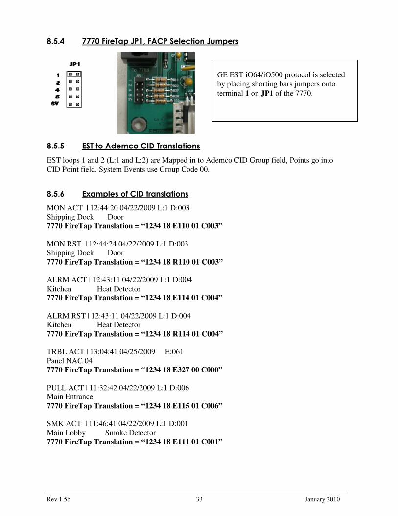
8.5.4 7770 FireTap JP1, FACP Selection Jumpers
8.5.5 EST to Ademco CID Translations
EST loops 1 and 2 (L:1 and L:2) are Mapped in to Ademco CID Group field, Points go into
CID Point field. System Events use Group Code 00.
8.5.6 Examples of CID translations
MON ACT | 12:44:20 04/22/2009 L:1 D:003
Shipping Dock Door
7770 FireTap Translation = “1234 18 E110 01 C003”
MON RST | 12:44:24 04/22/2009 L:1 D:003
Shipping Dock Door
7770 FireTap Translation = “1234 18 R110 01 C003”
ALRM ACT | 12:43:11 04/22/2009 L:1 D:004
Kitchen Heat Detector
7770 FireTap Translation = “1234 18 E114 01 C004”
ALRM RST | 12:43:11 04/22/2009 L:1 D:004
Kitchen Heat Detector
7770 FireTap Translation = “1234 18 R114 01 C004”
TRBL ACT | 13:04:41 04/25/2009 E:061
Panel NAC 04
7770 FireTap Translation = “1234 18 E327 00 C000”
PULL ACT | 11:32:42 04/22/2009 L:1 D:006
Main Entrance
7770 FireTap Translation = “1234 18 E115 01 C006”
SMK ACT | 11:46:41 04/22/2009 L:1 D:001
Main Lobby Smoke Detector
7770 FireTap Translation = “1234 18 E111 01 C001”
GE EST iO64/iO500 protocol is selected
by placing shorting bars jumpers onto
terminal 1 on JP1 of the 7770.

Rev 1.5b 34 January 2010
8.5.7 Examples of events and automation messages
The following examples were made using the configuration listed next:
• iO64 Firmware revision 01.20.00
• SA-232 optional RS-232 Card
• SIGA-270 Pullstation
• SIGA-PS Photo Smoke Detector
• SIGA-HFS Fixed Temperature Heat Detector
The 7770/7788F subscriber ID#9996 was interfaced to a 7705 (Multinet)
8.5.7.1 Smoke detector on Loop1 as Device 02 Loop1, device 02 will translate to Group 01, Zone 02.
The event is followed by a reset on the panel, that generates the E305 event, followed by the restoral.
FACP LCD
Multinet IPctrl
Automation results

Rev 1.5b 35 January 2010
8.5.7.2 Heat Detector Loop1 Device 01 Loop1, device 01 will translate to Group 01, Zone 01.
FACP LCD
Multinet IPctrl
Automation results
8.5.7.3 Pull Station Loop1 Device 03 Loop1, device 03 will translate to Group 01, Zone 03.
The event is followed by a reset on the panel, that generates the E305 event, followed by the restoral.
FACP LCD
Multinet IPctrl
Automation results

Rev 1.5b 36 January 2010
8.6 GE vigilant Models SV1 and SV2 with SA-232 optional RS-232 Card.
8.6.1 Fire Panel connection
SA-232 Ineterface card
The AES 7770 FireTap attaches to the SA-232 Interface Card. The SA-232 is an optional card
used for connecting a printer to the panel. It’s located in the upper left side of the panel, and
connects to J3 on the Main Circuit board. The 7770 connects to the SA-232 via 4 wires
between the terminal block TB? And the 7770 connector J1.
8.6.2 Connection supervision
Interface Supervision is by the panel only. The 7770 does not supervise the FACP. That means
that if the 7770 is disconnected from the panel, the 7770 will not issue an alarm. When the
panel is programmed to supervise the printer and when the wire from 7770 RTS is connected
to the PIN#3 (CTS), upon failure, the FACP will issue a trouble via one of its trouble relays.
The connection is considered compromised when it fails for more than 30 seconds, and the
EST will signal a printer fault. When the connection is restored the 7770 Firetap will send the
Vigilants’s printer restoral signal (R350).
8.6.3 Fire Panel programming
Program the Vigilant FACP for Supervision, following the steps below:
� Press the panel’s Menu Button
� choose Program
� choose Advanced Program.
� enter your level two Password
� choose Panel Configuration,
� choose Printer
� choose Type
� select Supervised
7770 JP1 SA-232 TB?
TX � RX
RX � TX
RTS � CTS
GND � GND
TX RX RTS CTS GND
GND CTS TX RX
NOTE: Event Notification to Printer is on
by Default.
The communication settings cannot be changed,
and when the jumpers are set for the FACP, they
are automatically set on the 7770 to 9600 Baud, 8
Data, No Parity, 1 Stop Bit.

Rev 1.5b 37 January 2010
� then Save.
8.6.4 7770 FireTap JP1, FACP Selection Jumpers
8.6.5 GE Vigilant to Ademco CID Translations
Vigilant loops 1 and 2 (L:1 and L:2) are mapped in to Ademco CID Group field, Points go into
CID Point field. System Events use Group Code 00.
8.6.6 Examples of CID translations
MON ACT | 12:44:20 04/22/2009 L:2 D:249
Shipping Dock Door
7770 FireTap Translation = “1234 18 E110 02 C249”
MON RST | 12:44:24 04/22/2009 L:2 D:249
Shipping Dock Door
7770 FireTap Translation = “1234 18 R110 02 C249”
SUPV ACT | 12:44:01 04/22/2009 L:2 D:250
Tamper Switch Mech Room
7770 FireTap Translation = “1234 18 E200 02 C250”
ALRM ACT | 12:43:11 04/22/2009 L:1 D:127
Kitchen Heat Detector
7770 FireTap Translation = “1234 18 E114 01 C127”
ALRM RST | 12:43:11 04/22/2009 L:1 D:127
Kitchen Heat Detector
7770 FireTap Translation = “1234 18 R114 01 C127”
TRBL ACT | 13:04:41 04/25/2009 E:061
Panel NAC 04
7770 FierTap Translation = “1234 18 E327 00 C000”
PULL ACT | 11:32:42 04/22/2009 L:2 D:126
Main Entrance
7770 FireTap Translation = “1234 18 E115 02 C126”
SMK ACT | 11:46:41 04/22/2009 L:1 D:001
Main Lobby Smoke Detector
7770 FireTap Translation = “1234 18 E111 01 C001”
GE Vigilant protocol is selected by placing
shorting bars jumpers onto terminal 2 and
8 on JP1 of the 7770.
Rev 1.5b 38 January 2010
8.6.7 Examples of events and automation messages
The following examples were made using the configuration listed next:
• Tested VS2, with Revision 01.20.00 Firmware.
• SA-232 optional RS-232 Card
• GSA-M278 Pull Station
• GSA-CR Control Relay Module
• Genesis Strobe
• GSA-CT1 Single Input Module
• GSA-CC1 Single Input Module
• GSA-CT2 Dual Input Module
• V-PS Photo Smoke Detector
• B4U Analog Standard Detector
• V-SLC Loop Expander Card
The 7770/7788F subscriber ID#9996 was interfaced to a 7705 (Multinet)
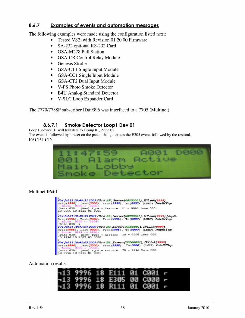
8.6.7.1 Smoke Detector Loop1 Dev 01 Loop1, device 01 will translate to Group 01, Zone 02.
The event is followed by a reset on the panel, that generates the E305 event, followed by the restoral.
FACP LCD
Multinet IPctrl
Automation results

Rev 1.5b 39 January 2010
8.6.7.2 Horn Strobe Trouble Dev126 Loop1, device 126 will translate to Group 01, Zone 126.
FACP LCD
Multinet IPctrl
Automation results
8.6.7.3 Heat Detector Loop1 Dev 127 Loop1, device 127 will translate to Group 01, Zone 127.
The event is followed by a reset on the panel, that generates the E305 event, followed by the restoral.
FACP LCD
Multinet IPctrl
Automation results

Rev 1.5b 40 January 2010
8.6.7.4 Pull Station Loop1 Dev 126 Loop1, device 126 will translate to Group 01, Zone 126.
The event is followed by a reset on the panel, that generates the E305 event, followed by the restoral
FACP LCD
Multinet IPctrl
Automation results
8.6.7.5 Monitor Module Loop1 Dev 249 Loop1, device 249 will translate to Group 01, Zone 249.
The event is followed by a reset on the panel, that generates the E305 event, followed by the restoral. . This panel
issues an extra code, an R305. This code is also issued via the dialer.
FACP LCD
Multinet IPctrl
Automation results

Rev 1.5b 41 January 2010
8.6.7.6 Monitor Module Tamper Loop1 Dev 249 Loop1, device 249 will translate to Group 01, Zone 249.
The event is followed by a reset on the panel, that generates the E305 event, followed by the restoral. . This panel
issues an extra code, an R305. This code is also issued via the dialer.
FACP LCD
Multinet IPctrl
Automation results

Rev 1.5b 42 January 2010
8.7 Siemens MXL Model MXL
8.7.1 Fire Panel connection
ANN-3, PIM-4 Serial Printer Port.
Hookup.
Five wires are attached between the Siemens Serial Printer Port and the AES 7770 FireTap.
8.7.2 Connection supervision
The connection between the 7770 and the FACP is supervised by the 7770. That means that if
the 7770 is disconnected from the FACP, the 7770 will issue an alarm message. The FACP
also supervises the connection, and it will also trip the trouble relay. The 7770 uses the CTS
line to supervise the connection.
7770 JP1 Serial Printer Port
Tx � Pin 2 - Rx
Rx � Pin 3 - Tx
Gnd � Pin 5 - Gnd
CTS � Pin 7 - RTS
RTS � Pin 8 – CTS
Pin 4 – tied to Pin6
Pin 6 – tied to Pin4
The AES 7770 FireTapII attaches to the
Siemens Serial Printer Port. The Serial
Printer Port is a DCE Female DB9
Connector . Note: Supported Baud Rate is
9600 N81, also Panel may have turned off
Serial Printer Port if no Printer, or FireTap
attached.

Rev 1.5b 43 January 2010
8.7.3 Fire Panel programming
Make sure that the serial printer port is enabled. For details, see the panel documentation.
8.7.4 7770 FireTap JP1, FACP Selection Jumpers
Siemens MXL Protocol is selected by placing a shorting bar jumper onto terminals 8 on JP1. This also selects
9600 Baud for the Siemens MXL Protocol. Place Supervision jumper on the JP1 SV to Supervise the Siemens to
7770 FireTap Cable.
8.7.5 Siemens MXL to Ademco CID Translations
Siemens MXL Modules are Mapped in to Ademco CID Group field, Device Numbers go into CID Point field.
System Events (Module 253 are Mapped to Group Code 00.) Module numbers greater than 99 are capped at 99
and Point is set to 999 to indicate an error.
8.7.6 Examples
ALARM 1-12 12:39:08 Oct 10, 2008 #1 MANUAL STATION MSI-1 Manual Station
7770 FireTap Translation = “1234 18 E115 33 C012” Pull Station Module 33 Point 12
TROUBLE IN 253 16:40:59 Oct 10, 2008 ****** M-DACT TESTING PANEL******, AC Fail or Brownout,
MXL Panel
7770 FireTap Translation = “1234 18 E301 00 C000” System Trouble AC
TROUBLE OUT 253 16:42:41 OCT 10, 2008 ****** M-DACT TESTING PANEL******,
AC Fail or Brownout, MXL Panel
7770 FireTap Translation = “1234 18 R301 00 C000” System Trouble AC
RESET 16:52:32 Oct 10, 2008 System Reset.
7770 FireTap Translation = “1234 18 E305 00 C000” System Reset
TROUBLE IN 253 16:55:44 Oct 10, 2008 ****STANFORD AES TEST PANRL****,
Battery Fuse/Wiring Open, MXL Panel
7770 FireTap Translation = “1234 18 E302 00 C000” Low System Battery
TROUBLE IN 1-11 17:05:34 Oct 10, 2008 HEAT DETECTOR, Dev communication
Error, FPT-11 Thermal Only Det.
7770 FireTap Translation = “1234 18 E380 01 C011” Sensor Problem
ALARM 100-11 15:06:50 Sep 20,2007 #1 GENERAL ALARM, Pseudo I/O
7770 FireTap Translation = “1234 18 E110 99 C999” Error

Rev 1.5b 44 January 2010
8.7.7 Examples of events and automation messages
The following examples were made using the configuration listed next:
FP-11 Smoke Detector,
FPT-11 Fixed Heat Detector,
Pull Station.
Tested with Revision V16.0
Tested MMB 20.16, ANN-2 Rev 1.0
The 7770/7788F subscriber ID#9996 was interfaced to a 7705 (Multinet)
8.7.7.1 Monitor module tamper, Loop1 Device 14 Monitor Module 1 device 14 will translate to Group 01, Zone 14.
FACP LCD
Multinet IPctrl
Automation results

Rev 1.5b 45 January 2010
8.7.7.2 Monitor module WaterFlow Loop1 Device 13 Monitor Module 1 device 14 will translate to Group 01, Zone 1.
FACP LCD
Multinet IPctrl
Automation results
Rev 1.5b 46 January 2010
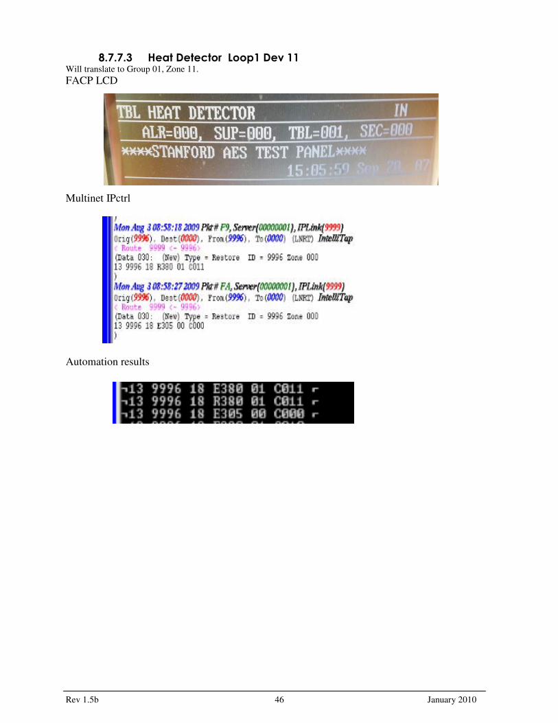
8.7.7.3 Heat Detector Loop1 Dev 11 Will translate to Group 01, Zone 11.
FACP LCD
Multinet IPctrl
Automation results

Rev 1.5b 47 January 2010
8.7.7.4 Smoke Detector Loop1 Dev 10 Will translate to Group 01, Zone 10.
FACP LCD
Multinet IPctrl
Automation results

Rev 1.5b 48 January 2010
8.7.7.5 Pull Station Loop1 Dev 12 Will translate to Group 01, Zone 12.
FACP LCD
Multinet IPctrl
Automation results

Rev 1.5b 49 January 2010
FCI-7100 J3 7770 J1
1 NC
2 � TX J1-1
3 � Gnd J1-5
4 � Gnd J1-5
5 � Rx J1-2
6 � RTS J1-3
8.8 FCI-7100 Tested Version 6.3 - 001
8.8.1 Fire Panel connection
The AES 7770 FireTap II attaches to FCI-7100 Serial Port J3 (RJ-11 Teleco).
Five wires are attached between J3 on the FCI-7100 FACP Modular RJ-11, Jack, and J1 on the AES 7770
FireTap.
8.8.2 Connection supervision
The connection between the 7770 and the FACP is supervised by the 7770. That means that if
the 7770 is disconnected from the FACP, the 7770 will issue an alarm message. The FACP
also supervises the connection, and it will also trip the trouble relay. The 7770 uses the CTS
line to supervise the connection. The FACP also supervises the 7770.
8.8.3 Fire Panel programming
Consult manual for port programming.
Program Port for 9600 Baud, 8 Data Bits, NoParity, Stop Bits
Program Port for
• 9600 Baud,
• 8 Data Bits,
• NoParity,
• 1 Stop Bits
Rev 1.5b 50 January 2010
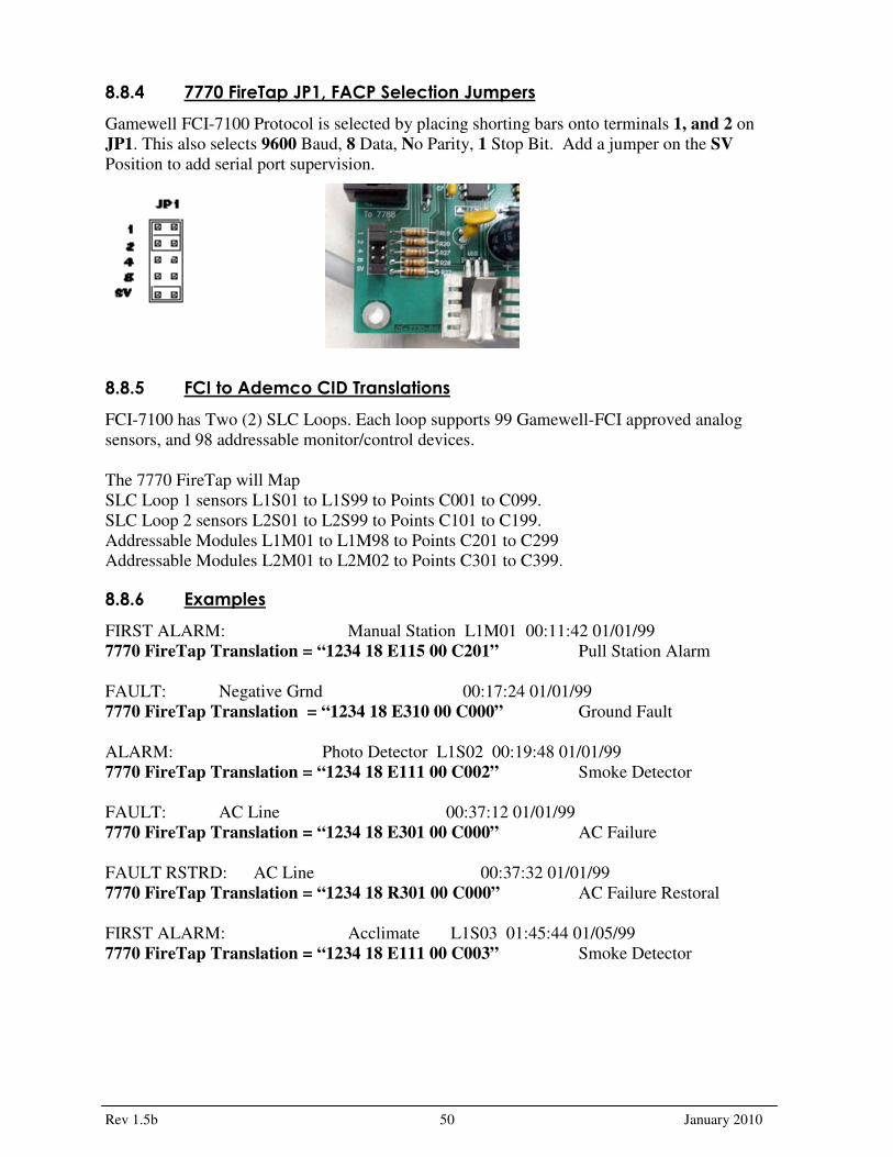
8.8.4 7770 FireTap JP1, FACP Selection Jumpers
Gamewell FCI-7100 Protocol is selected by placing shorting bars onto terminals 1, and 2 on
JP1. This also selects 9600 Baud, 8 Data, No Parity, 1 Stop Bit. Add a jumper on the SV
Position to add serial port supervision.
8.8.5 FCI to Ademco CID Translations
FCI-7100 has Two (2) SLC Loops. Each loop supports 99 Gamewell-FCI approved analog
sensors, and 98 addressable monitor/control devices.
The 7770 FireTap will Map
SLC Loop 1 sensors L1S01 to L1S99 to Points C001 to C099.
SLC Loop 2 sensors L2S01 to L2S99 to Points C101 to C199.
Addressable Modules L1M01 to L1M98 to Points C201 to C299
Addressable Modules L2M01 to L2M02 to Points C301 to C399.
8.8.6 Examples
FIRST ALARM: Manual Station L1M01 00:11:42 01/01/99
7770 FireTap Translation = “1234 18 E115 00 C201” Pull Station Alarm
FAULT: Negative Grnd 00:17:24 01/01/99
7770 FireTap Translation = “1234 18 E310 00 C000” Ground Fault
ALARM: Photo Detector L1S02 00:19:48 01/01/99
7770 FireTap Translation = “1234 18 E111 00 C002” Smoke Detector
FAULT: AC Line 00:37:12 01/01/99
7770 FireTap Translation = “1234 18 E301 00 C000” AC Failure
FAULT RSTRD: AC Line 00:37:32 01/01/99
7770 FireTap Translation = “1234 18 R301 00 C000” AC Failure Restoral
FIRST ALARM: Acclimate L1S03 01:45:44 01/05/99
7770 FireTap Translation = “1234 18 E111 00 C003” Smoke Detector

Rev 1.5b 51 January 2010
8.8.7 Examples of events and automation messages
The following examples were made using the configuration listed next:
MS-7AF Pull Station,
AOM-2RF Relay,
AMM-4F Monitor Module,
PID-SS Monitor Module,
ASD-PL2F Smoke Detectors,
MCS-ACCLIMATE2F Smoke Detector.
Interface Supervision is by FireTap. Interface is Bidirectional.
Tested with Revision 6.3-001 Firmware.
The 7770/7788F subscriber ID#9996 was interfaced to a 7705 (Multinet)
8.8.7.1 Pull Station 1 on Loop 1 Loop1 1, module 1, will translate to Group 00, Zone 201
The event is followed by a reset on the panel, that generates the E305 event.
FACP LCD
Multinet IPctrl
Automation results

Rev 1.5b 52 January 2010
8.8.7.2 Smoke Detector Loop1 Sensor 1 Loop1 1, sensor 1, will translate to Group 00, Zone 1
The event is followed by a reset on the panel, that generates the E305 event.
FACP LCD
Multinet IPctrl
Automation results
8.8.7.3 Smoke Detector Loop1 Sensor 2 Loop1 1, sensor 1, will translate to Group 00, Zone 2
The event is followed by a reset on the panel, that generates the E305 event.
FACP LCD
Multinet IPctrl
Automation results

Rev 1.5b 53 January 2010
8.8.7.4 Pull Station 4 on Loop 1 Loop1 1, module 4, will translate to Group 00, Zone 204
The event is followed by a reset on the panel, that generates the E305 event.
FACP LCD
Multinet IPctrl
Automation results
8.8.7.5 Pull Station 30 on Loop 1 Loop1 1, module 30, will translate to Group 00, Zone 230
The event is followed by a reset on the panel, that generates the E305 event.
FACP LCD
Multinet IPctrl
Automation results

Rev 1.5b 54 January 2010
9. Built-in tests of the 7770 9.1 Required material
� 7770 (UUT = Unit Under Test)
� Test cable
� Power soruce for the 7770
9.2 Test cable construnction . Loop J2 (Radio Interface) to J1 (FACP Interface).
J2 Pin 2 RTS J1 DSR to RTS (RTS is Isolated output to Radio DSR input).
J2 Pin 3 � CTS J1 DTR to CTS (DTR is Radio Output to CTS Isolated Input).
J2 Pin 4 TX J1 Rx to Tx (Radio Tx output to Isolated Rx input).
J2 Pin 5 � RX J1 Tx to RX (Isolated Tx output to Radio Rx input).
J2 Pin 6 � GND Gnd to Gnd.
9.3 Activating the built-in test mode The built-in test mode is activated when all four Selection jumpers are grounded.
9.4 Functions verified by the built-in test The 7770 has 2 LED's these will indicate Problems, or Success.
J2 DTR line Cannot be controlled (Tied to our reset signal)
but look for J1 CTS signal high. If not light Red D4 LED.
Toggle J1 RTS Signal, Look for J2 DTR line to Toggle as well.
If not light Yellow LED D5.
Send a Test Mesage from J2 Tx to J1 Rx. If we receive the message,
and or Terminator. Fast Blink the Red LED.
Got a Message but it does not match search string. Slow Blink Red LED.
Send a test message back from the Isolated port into the Radio Serial port.
If we don't receive Message/Terminator. Fast Blink Yellow LED.
. If we received a message but not a text match. Slow Blink Yellow LED.
. All tests passed. Alternately blink Yellow, and then Red LED.

Rev 1.5b 55 January 2010
9.5 Step-by-step procedure 1. Plug the test shorting block on to JP1. All of the Selection jumper
positions are selected. This selects the 7770’s Built in Test Routines
2. Attach test cable to 7770’s, 5 Position Terminal Block J1. Pin 1 is Marked with Black Band, and goes into J1 Left most Position (Tx.) Tighten all five Terminal Block Screws.
3. Attach Power / Battery leads to a power source / battery. The red wire attaches to battery + (Positive) Terminal, black wire attaches to battery – (Negative) Terminal.
4. Now plug the RJ11 end of the test cable into J2. This powers up the 7770 and starts the Built in Test.
5. The First test is the blinking of the two 7770’s LED’s in Unison. This Test that the LED’s work
and can be controlled by the Micro.
6. Now remove the test shorting block from JP1. This starts the two Communication Serial ports on the 7770. Both LED’s indicators will be turned off during the tests.
7. If a test fails? A LED Diagnostic Pattern will be signaled, and all further tests will be suspended.
8. If a test fails? Make sure that the test cable is connected properly.
When all tests are completed with out error. The Success Diagnostic Pattern will be illuminated. This Pattern is to
Alternately Blink each LED, Yellow, and then the Red.
9.6 LED Diagnostic Test Patterns (Built in Test) Red Status LED (D4) On Solid = Isolated CTS Line Problem.
Yellow PanelAct LED (D5) On Solid = Radio DSR, or Isolated RTS Line Problem.
Red Status LED (D4) Slow Blink = Radio to Isolated Serial Message. Text Match Problem.
Red Status LED (D4) Fast Blink = Radio to Isolated Serial Message. No Message or Terminator.
Yellow PanelAct LED (D5) Slow Blink = Isolated to Radio Serial Message. Text Match Problem.
Yellow PanelAct LED (D5) Fast Blink = Isolated to Radio Serial Message. No Message or Terminator.
Yellow PanelAct (D5), and Red Status (D4) LED's Blink together = LED Test + Waiting to Start.
Yellow PanelAct (D5), and Red Status (D4) LED's Blink Alternately = Success All Test Pass.

Rev 1.5b 56 January 2010
10. CONNECT A ZONE ON THE SUBSCRIBER UNIT IN
ADDITION TO THE FireTap It is strongly recommended that a least one output of the alarm panel be connected to the
AES Subscriber Unit when using the FireTap. The activated zone serves as a general
alarm. The alarm monitoring screen should comment that additional information should
follow and what action to take if it does not. If the alarm panel has the necessary outputs
you can send general alarms for more specific clarification, such as General Fire,
Burglary, Panic, etc.
TEST PROCEDURES
� Notify the Central Station that a test is in progress.
� Trip the alarm control panel. The FireTap LED indicator will blink as the panel’s data
message is recognized and accepted.
� Check with the central station that the correct message was received.
11. Contact Information AES Corporation
285 Newbury Street
Peabody, Massachusetts 01960 USA
Telephone: (978) 535-7310
Toll Free: (800) 237-6387
FAX: (978) 535-7313 Email: [email protected]
12. Revision History Date Revision Author Notes
2008DEC14 1.0 Eng Initial draft (BG,JB,RD)
2008DEC15 1.1 Eng RD review, figure inclusion
2008DEC16 1.2 Eng Led pattern inclusion
2008DEC16 1.3 Eng Multiple panels inclusion - partial
2009SEP09 1.4 Eng New panels inclusion
2009OCT28 1.5 Eng Updated with beta feedback
GENERAL
Telephone: (978) 535-7310
Email: [email protected]
SALES
Telephone: (978) 535-7310
Email: [email protected]
SUPPORT & SERVICES
Telephone: (978) 535-7310 Option 4
Email: [email protected]

Rev 1.5b 57 January 2010
This Page intentionally
left Blank

Rev 1.5b 58 January 2010