Aerospace Maintenance Competition · Aerospace Maintenance Competition Presented by Event Manual...
81
Aerospace Maintenance Competition Presented by Event Manual The Aerospace Maintenance Council, a non-profit organization, promotes and supports the aerospace maintenance community. The council’s flagstone event, the Aerospace Maintenance Competition (AMC), recognizes and celebrates the aviation maintenance technician, and raises awareness of the knowledge and skill required to maintain safe, airworthy aircraft, worldwide. The competition is held annually in conjunction with Aviation Week’s MRO Americas. The 2018 event will take place on April 9- 12 at the Orange County Convention Center in Orlando. The purpose of this manual is to provide participants information about the competition and its competitive events. It will be revised periodically while events are added and modified, please check back often to ensure you’re referencing the most current version. Send comments and suggested revisions to [email protected].
Transcript of Aerospace Maintenance Competition · Aerospace Maintenance Competition Presented by Event Manual...

Aerospace Maintenance Competition Presented by
Event Manual The Aerospace Maintenance Council, a non-profit organization, promotes and supports the aerospace maintenance community. The council’s flagstone event, the Aerospace Maintenance Competition (AMC), recognizes and celebrates the aviation maintenance technician, and raises awareness of the knowledge and skill required to maintain safe, airworthy aircraft, worldwide. The competition is held annually in conjunction with Aviation Week’s MRO Americas. The 2018 event will take place on April 9-12 at the Orange County Convention Center in Orlando.
The purpose of this manual is to provide participants information about the competition and its competitive events. It will be revised periodically while events are added and modified, please check back often to ensure you’re referencing the most current version.
Send comments and suggested revisions to [email protected].

Aerospace Maintenance Competition
Event Manual
Page 2 of 81
This document is the property of the Aerospace Maintenance Council, it may not be reproduced without express written consent. Uncontrolled printed versions of this document are for reference only, users are responsible for verifying its currency against the master electronic version available on the AMC website.
Revision Number: 05
Original Issue Date: 01/25/2018
Revision Date: 03/25/2018
Table of Contents
About............................................................................................................................................................. 4
Schedule of Events ........................................................................................................................................ 4
About MRO Americas .................................................................................................................................... 4
Venue ............................................................................................................................................................ 4
Hotel Accommodation .................................................................................................................................. 5
Exhibit Hours and Floor Access ..................................................................................................................... 5
Rules .............................................................................................................................................................. 5
Scoring........................................................................................................................................................... 6
Sponsor and Event Setup .............................................................................................................................. 7
Shipping information .................................................................................................................................... 7
Competition Layout ...................................................................................................................................... 8
Team and Sponsor Recognition .................................................................................................................... 9
Orientation Briefing ...................................................................................................................................... 9
Event Grouping ............................................................................................................................................. 9
Teams .......................................................................................................................................................... 11
Events .......................................................................................................................................................... 14
#1 Daniels Manufacturing Electrical Troubleshooting ............................................................................ 19
#2 Daniels Manufacturing Corporation Safe-T-Cable ............................................................................. 21
#3 Airbus A320 CAT III Certification ........................................................................................................ 23
#4 Non-Destructive Testing—CANCELLED .............................................................................................. 24
#5 United Fuel Tank Entry Precautions ................................................................................................... 25
#6 Boroscope—CANCELLED .................................................................................................................... 27
#7 Eastern Florida State Space Vehicle - Vacuum Loading Operation .................................................... 28
#8 Spectro Scientific Oil Test Analysis ..................................................................................................... 33
#9 Abaris Training Composite Repair ...................................................................................................... 34
#10 PPG Aerospace Cockpit and Wing Sealant ..................................................................................... 36
#11 ULTRAX Condition Based Intelligence TM (CBI TM) ........................................................................... 37
#12 Atheer AiR & American Airlines Augmented Reality Pedestal ....................................................... 38
#13 Embry-Riddle Precision Measurement .......................................................................................... 39

Aerospace Maintenance Competition
Event Manual
Page 3 of 81
This document is the property of the Aerospace Maintenance Council, it may not be reproduced without express written consent. Uncontrolled printed versions of this document are for reference only, users are responsible for verifying its currency against the master electronic version available on the AMC website.
Revision Number: 05
Original Issue Date: 01/25/2018
Revision Date: 03/25/2018
#14 JetBlue University ADS-B Troubleshooting .................................................................................... 41
#15 Barfield Fuel Quantity .................................................................................................................... 42
#16 Barfield Pitot Static ........................................................................................................................ 45
#17 FedEx Express Turbine Engine ....................................................................................................... 46
#18 Indian Hills Community College Magneto ..................................................................................... 50
#19 Boeing Cable Rigging ...................................................................................................................... 52
#20 American Airlines APU Burner Can ................................................................................................ 54
#21 Pratt & Whitney Geared Turbo Fan Engine ................................................................................... 56
#22 W.L. Gore & Associates, Inc. Dry Sealant Panel Installation .......................................................... 57
#23 Alaska Airlines External Power Receptacle Event .......................................................................... 61
#24 Nida Corporation Power Troubleshooting ..................................................................................... 63
#25 Boeing Fiber Optics ........................................................................................................................ 65
#26 Aircraft Maintenance Technicians Association Charles E. Taylor Exam ........................................ 69
#27 Aerospace Maintenance Competition Safety Wiring .................................................................... 70
#28 Advanced Torque Products Accurate Torqueing ........................................................................... 71
#29 U.S. Air Force Flex Fluid Lines ........................................................................................................ 72
#30 Alberth Aviation Wheel and Brake Removal and Installation ....................................................... 75
Aerospace Maintenance Competition
Event Manual
Page 4 of 81
This document is the property of the Aerospace Maintenance Council, it may not be reproduced without express written consent. Uncontrolled printed versions of this document are for reference only, users are responsible for verifying its currency against the master electronic version available on the AMC website.
Revision Number: 05
Original Issue Date: 01/25/2018
Revision Date: 03/25/2018
About
The AMC provides an opportunity for current and future maintenance professionals to showcase their abilities and see how they stack up against peers across the country. Five-member teams compete in maintenance events intended to test skill and knowledge required of an aviation maintenance technician. Teams may enter one of six categories:
• Commercial Aviation • General Aviation • Space • Education • Military • MRO/OEM
The competition is managed by the Aerospace Maintenance Council’s AMC committee. It is supported through the generous contributions of the aerospace community. Sponsors host events, provide prizes and make monetary contributions.
Schedule of Events
• Sunday, April 8, 12:00 PM – 5:00 PM: Event Setup (sponsors and judges only) • Monday, April 9, 8:15 AM – 9:00 AM: Judge Briefing (exhibit hall doors open at 8:00 AM) • Monday, April 9, 9:00 AM – 12:00 PM: Competitor Orientation • Monday, April 9, 1:30 PM – 5:00 PM: AMC Day 0 ("soft start") • Tuesday, April 10, 9:00 AM – 5:00 PM: AMC Day 1 • Wednesday, April 11, 9:00 AM – 2:30 PM: AMC Day 2 • Thursday, April 12, 9:00 AM – 12:00 PM: Award Ceremony
About MRO Americas
The competition is held on the exhibit floor of MRO Americas, an annual gathering of aviation maintenance professionals that incorporates informative conference sessions and a showcase of new and innovative products, technologies, offerings and services. More information about the location and logistics can be found on that event’s website.
The AMC will take place at MRO Americas Booth Number 100.
The exhibit hall layout is available at http://mroamericas.aviationweek.com/am18/Public/eventmap.aspx?shavailable=1&shexhlist=1.
Venue
MRO Americas and the AMC will take place at the Orange County Convention Center in Orlando, 9899 International Drive, North Concourse, halls A&B.

Aerospace Maintenance Competition
Event Manual
Page 5 of 81
This document is the property of the Aerospace Maintenance Council, it may not be reproduced without express written consent. Uncontrolled printed versions of this document are for reference only, users are responsible for verifying its currency against the master electronic version available on the AMC website.
Revision Number: 05
Original Issue Date: 01/25/2018
Revision Date: 03/25/2018
Hotel Accommodation
Aviation Week has reserved room blocks at a discounted rate for all MRO Americas participants. Reserve accommodation at http://mroamericas.aviationweek.com/am18/Public/Content.aspx?ID=1068009&sortMenu=112003.
Exhibit Hours and Floor Access
To access the competition area, all attendees must register for a floor pass at https://www.eiseverywhere.com/ereg/newreg.php?eventid=273265&categoryid=2131470. Individuals must be 16 years and older to register.
If completed in advance, registration is free for competitors, instructors/coaches, sponsors, visitors and volunteers.
Only event competitors, instructors/coaches, sponsors, and volunteers are permitted to access the event floor prior to official show opening times.
Badges may be picked up on site at the MRO Americas Registration Area – located on the mail level of the Convention Center’s north hall.
Registration Hours
• April 9 from 8:00 AM – 5:00 PM • April 10, 8:00 AM – 5:30 PM • April 11, 8:00 AM – 5:30 PM • April 12, 8:00 AM – 2:30 PM
Exhibit Hall Hours
• Tuesday April 10, 2018 10:30 AM – 5:30 PM • Wednesday April 11, 2018 9:30 AM – 5:30 PM • Thursday April 12, 2018 9:30 AM – 1:00 PM
Rules
1) Each team must consist of five team members. 2) Competitors must be either certificated by a national aviation authority (e.g., hold an FAA mechanic
certificate), enrolled in a certificated aviation maintenance technician school, employed by a certificated repair station or manufacturing facility, or a member of the armed forces.
3) Each team is allowed, but not required, to designate alternate(s) in the event a member is not able to participate the day of the competition.
4) School category teams are comprised of five currently-enrolled students. Individuals that graduated the institution in the last six months that are not currently employed by an aviation-related company are also eligible to compete. Instructors are not eligible to compete.
5) Teams have 15 minutes to complete each competitive event. 6) There is a five-minute break between the end of one event and the beginning of the next event.
Competitors present in the five minutes preceding the event start time may review task cards,

Aerospace Maintenance Competition
Event Manual
Page 6 of 81
This document is the property of the Aerospace Maintenance Council, it may not be reproduced without express written consent. Uncontrolled printed versions of this document are for reference only, users are responsible for verifying its currency against the master electronic version available on the AMC website.
Revision Number: 05
Original Issue Date: 01/25/2018
Revision Date: 03/25/2018
materials, or prepare for the event, as permitted by the event judge. Time will not be credited for competitors arriving after the designated start time.
7) Each team member must sign a release of liability to participate, completed at check-in. 8) Each event has a designated number of team member(s) eligible to participate. For events that
require less than five team members, the team will assign member(s) of their choice to compete. 9) If a team member completes an event before the 15-minute time limit, he/she may assist fellow
team member(s) in other events. 10) Scores are calculated based on the standard event score sheet. 11) Event sponsors provide judges for each event. Scores are calculated based on the standard score
sheet, and at the judge’s discretion. Problems and/or questions may be addressed during an event at the judge’s discretion. Judges may stop the clock to remedy problems or answer a question at their discretion. Appeals to a judge decision may be brought to the AMC chairman.
12) Scores provided verbally at the completion of an event are not official until properly recorded. 13) Scores provided to the scoring committee are considered final once received. The AMC chairman
reserves the right to modify final scores up until the awards ceremony. 14) The three teams with the lowest score in each category will be recognized at the awards ceremony.
The team with the lowest score across all categories will be awarded the William F. “Bill” O’Brien Award for Excellence in Aircraft Maintenance.
15) The AMC chairman reserves the right to remove any team member(s) from the competition for, but not limited to, unprofessional behavior, cheating, etc.
16) The AMC committee reserves the right to alter events and/or rules prior to or during the competition and will make best efforts to notify all team members of the change.
17) Participants are expected to observe personal protection equipment requirements throughout the competition. Failure to observe safety practices will result in penalties.
18) All required tools and protection equipment is provided by event sponsors. Personal tools are not allowed.
19) Judges will receive all final, tallied scores for their event the evening before the awards ceremony to ensure final scores are correct and consistent with their own notes.
Scoring
Judges will utilize the standard AMC score sheet to calculate team scores for each event. Event scores are calculated by adding the total amount of time expended to complete the event, plus penalties assessed. Standard penalties are assessed for—
• Failure to follow procedures • Improper use of tools • Failure to properly store tools and/or equipment • Improper use of safety equipment • Incomplete or incorrect recordkeeping • Unprofessionalism • Other, and provided for by the specific event or at the judge’s discretion
Aerospace Maintenance Competition
Event Manual
Page 7 of 81
This document is the property of the Aerospace Maintenance Council, it may not be reproduced without express written consent. Uncontrolled printed versions of this document are for reference only, users are responsible for verifying its currency against the master electronic version available on the AMC website.
Revision Number: 05
Original Issue Date: 01/25/2018
Revision Date: 03/25/2018
Any additional penalties that will be considered for a particular event are detailed in the event criteria.
Sponsor and Event Setup
Event, bronze- and gold-level sponsors will setup competitive events and exhibit tables on Sunday, April 8 from noon to 5:00 PM. Event breakdown will take place when the exhibit floor closes, Thursday, April 12 from 1:00 PM to 10:30 PM.
All exhibitor materials must be removed from the exhibit facility by Friday, April 13, 2018 at 1:00 PM.
All event spaces will be pre-set with a 120V 5 Amp (500w) Single Outlet, two standard six-foot tables and two chairs. Sponsors are responsible for costs associated with any additional freight or facility needs (i.e., furniture, electric, wireless internet, carpet, etc.). Contact [email protected] to coordinate these additional requirements.
Information regarding shipments and exhibit hall access is in the MRO Americas Exhibitor Manual available at http://mroamericas.aviationweek.com/am18/Public/Content.aspx?ID=1068012&sortMenu=115000.
Shipping information
To ensure proper delivery, shipments should identify the AMC Booth #100, and the AMC-designated event/table space (for example, 100-01, 100-02, etc.), as provided for in the AMC layout (below). (Space assignments will be made in a subsequent revision to this manual.)
Warehouse Shipping (for materials arriving after March 9 and before April 2):
Aerospace Maintenance Competition / Booth #100-XX MRO Americas 2018 C/O FREEMAN 10088 GENERAL DR ORLANDO, FL 32824 (407) 816-7900
Show Site Shipping Address (for materials arriving after April 7):
Aerospace Maintenance Competition / Booth #100-XX MRO Americas 2018 C/O FREEMAN ORANGE COUNTY CONVENTION CENTER - NORTH BUILDING 9400 UNIVERSAL BLVD ORLANDO, FL 32819-9340

Aerospace Maintenance Competition
Event Manual
Page 8 of 81
This document is the property of the Aerospace Maintenance Council, it may not be reproduced without express written consent. Uncontrolled printed versions of this document are for reference only, users are responsible for verifying its currency against the master electronic version available on the AMC website.
Revision Number: 05
Original Issue Date: 01/25/2018
Revision Date: 03/25/2018
Competition Layout
A new layout will allow for perimeter walkways and enhanced spectator viewing. The floorplan is subject to change.
Aerospace Maintenance Competition
Event Manual
Page 9 of 81
This document is the property of the Aerospace Maintenance Council, it may not be reproduced without express written consent. Uncontrolled printed versions of this document are for reference only, users are responsible for verifying its currency against the master electronic version available on the AMC website.
Revision Number: 05
Original Issue Date: 01/25/2018
Revision Date: 03/25/2018
Team and Sponsor Recognition
Sponsor and team logos will be displayed on event signage and in the event program. Signage will be created and displayed at the AMC committee’s discretion. Teams and sponsors should not bring banners or signage to the competition.
Orientation Briefing
The briefing takes place the day before the competition begins and is mandatory for all team members and judges. Guests are not permitted.
Each judge will provide an overview and evaluation criteria for their event, followed by questions and answers.
Following the overview, competitors will have the opportunity to walk around the competition floor to get a close-up look at each event and ask further questions. If practical that event’s judge may offer tutorials to ensure all competitors understand the event criteria and requirements.
MRO Americas trade show exhibitors will be setting up their respective booths on the showroom floor during the AMC orientation. As such, all AMC participants are asked to stay in the AMC area during that time, please do not wander around the show room floor.
Event Grouping
Teams members will compete in simultaneous events according to the following event group schedule.
Group Event Team Members Required
1 #10 PPG Aerospace Cockpit and Wing Sealant 5
2 #17 FedEx Express Turbine Engine
#29 U.S. Air Force Flex Fluid Lines
N/A Boroscope—CANCELLED
3
2
0
3 #18 Indian Hills Community College Magneto
N/A Non-Destructive Testing—CANCELLED
#22 W.L. Gore & Associates, Inc. Dry Sealant Panel Installation
2
0
3
4 #25 Boeing Fiber Optics
#11 ULTRAX Condition Based Intelligence TM (CBI TM)
#13 Embry-Riddle Precision Measurement
2
2
1

Aerospace Maintenance Competition
Event Manual
Page 10 of 81
This document is the property of the Aerospace Maintenance Council, it may not be reproduced without express written consent. Uncontrolled printed versions of this document are for reference only, users are responsible for verifying its currency against the master electronic version available on the AMC website.
Revision Number: 05
Original Issue Date: 01/25/2018
Revision Date: 03/25/2018
Group Event Team Members Required
5 #23 Alaska Airlines External Power Receptacle
#1 Daniels Manufacturing Electrical Troubleshooting
#3 Airbus A320 CAT III Certification
2
2
1
6 #16 Barfield Pitot Static
#5 United Fuel Tank Entry Precautions
#8 Spectro Scientific Oil Test Analysis
2
2
1
7 #14 JetBlue University ADS-B Troubleshooting
#24 Nida Corporation Power Troubleshooting
#2 Daniels Manufacturing Corporation Safe-T-Cable
2
2
1
8 #21 Pratt & Whitney Geared Turbo Fan Engine
#7 Eastern Florida State Space Vehicle - Vacuum Loading Operation
#26 AMTA Charles E. Taylor Exam
2
2
1
9 #19 Boeing Cable Rigging
#30 Alberth Aviation Wheel and Brake Removal and Installation
2
3
10 #9 Abaris Training Composite Repair
#20 American Airlines APU Burner Can
#27 Aerospace Maintenance Competition Safety Wiring
2
2
1
11 #15 Barfield Fuel Quantity
#12 American Airlines & Atheer AiR Augmented Reality Pedestal
#28 Advanced Torque Products Accurate Torqueing
2
2
1

Aerospace Maintenance Competition
Event Manual
Page 11 of 81
This document is the property of the Aerospace Maintenance Council, it may not be reproduced without express written consent. Uncontrolled printed versions of this document are for reference only, users are responsible for verifying its currency against the master electronic version available on the AMC website.
Revision Number: 05
Original Issue Date: 01/25/2018
Revision Date: 03/25/2018
Teams
The following teams are confirmed to participate in the 2018 event. Each team is assigned a team number that will be used as identifiers on the team schedule and to facilitate scoring:
Team No. Team Name Category
1 American Airlines - DFW Commercial
2 Aviation Institute of Maintenance - Houston School
3 Alaska Airlines - ANC Commercial
4 Australian Licenced Aircraft Engineers Association MRO/MFR
5 JetBlue Commercial
6 Eastern Florida State College School
7 China Eastern Airlines Commercial
8 Pittsburgh Institute of Aeronautics - Hagerstown School
9 United Airlines - MCO Commercial
10 TulsaTech School
11 UPS Commercial
12 United States Air Force - McChord Military
13 FedEx Express - INDY MRO/MFR
14 Mohawk Valley Community College School
15 United States Air Force - Ogden Air Logistics Complex Military
16 Phillips 66 General Aviation
17 United States Coast Guard - Aero Engineers Military
18 Boeing MRO/MFR
19 Qantas Commercial

Aerospace Maintenance Competition
Event Manual
Page 12 of 81
This document is the property of the Aerospace Maintenance Council, it may not be reproduced without express written consent. Uncontrolled printed versions of this document are for reference only, users are responsible for verifying its currency against the master electronic version available on the AMC website.
Revision Number: 05
Original Issue Date: 01/25/2018
Revision Date: 03/25/2018
Team No. Team Name Category
20 United States Army - 128th Aviation Brigade Military
21 American Airlines - DWH MRO/MFR
22 Liberty University School
23 Alaska Airlines - SEA Commercial
24 Middle Tennessee State University - Team 1 School
25 Horizon Air Commercial
26 United States Coast Guard - Air Station Clearwater Military
27 FedEx Express - MEM MRO/MFR
28 United States Air Force - Seymour Johnson Military
29 West Atlantic Line Commercial
30 Broward College - Team 1 School
31 Pratt & Whitney - WiseMen MRO/MFR
32 United States Air Force - Altus A-Team Military
33 United Airlines - CLE Commercial
34 Pittsburgh Institute of Aeronautics - Pittsburgh School
35 Jetstar Commercial
36 Aviation Institute of Maintenance - Irving School
37 United Airlines - SFO Commercial
38 Middle Tennessee State University - Team 2 School
39 Flybe MRO/MFR
40 Pittsburgh Institute of Aeronautics - Myrtle Beach School

Aerospace Maintenance Competition
Event Manual
Page 13 of 81
This document is the property of the Aerospace Maintenance Council, it may not be reproduced without express written consent. Uncontrolled printed versions of this document are for reference only, users are responsible for verifying its currency against the master electronic version available on the AMC website.
Revision Number: 05
Original Issue Date: 01/25/2018
Revision Date: 03/25/2018
Team No. Team Name Category
41 United States Air Force - Fairchild Military
42 Indian Hills Community College School
43 HAECO Americas MRO/MFR
44 Salt Lake Community College School
45 Pratt & Whitney - WiseWomen MRO/MFR
46 West Los Angeles College School
47 United States Air Force - Eglin 33rd AMXS Military
48 Utah State University School
49 American Airlines - TUL MRO/MFR
50 Broward College - Team 2 School
51 Airborne Maintenance & Engineering Services MRO/MFR
52 United States Air Force - McConnell 22 MXG/931 MXG Military
53 Monarch Aircraft Engineering Limited - Team 1 Commercial
54 Pittsburgh Institute of Aeronautics - Youngstown School
55 United Airlines - HOU MRO/MFR
56 Vaughn College of Aeronautics and Technology School
57 Elevate Aviation Commercial
58 Southern Illinois University Carbondale - Team 1 School
59 United States Marine Corp - VMM 165 Military
60 Monarch Aircraft Engineering Limited - Team 2 School
61 United States Coast Guard - C-27J APO Military

Aerospace Maintenance Competition
Event Manual
Page 14 of 81
This document is the property of the Aerospace Maintenance Council, it may not be reproduced without express written consent. Uncontrolled printed versions of this document are for reference only, users are responsible for verifying its currency against the master electronic version available on the AMC website.
Revision Number: 05
Original Issue Date: 01/25/2018
Revision Date: 03/25/2018
Team No. Team Name Category
62 Southern Illinois University Carbondale - Team 2 School
63 United States Air Force - Dyes Military
64 TulsaTech Aerospace Academy School
65 United States Air Force - Hurlburt Field 1 SOAMXS Military
66 Aviation High School School
67 AVIANCA Commercial
68 Del Mar College School
69 United States Marine Corp - MALS 39 Military
70 National Center for Aviation Training School
71 United States Air Force - Warner Robins Air Logistics Center Military
72 United States Air Force - Oklahoma City Air Logistics Complex Military
Events
The AMC consists of various events to test the knowledge and skills needed of today’s aviation technician. All teams will compete in every event, teams are responsible for assigning individual competitors to each event. The number of competitors required to complete each event is provided in the event grouping, above.
Events will be added and revised as necessary, check the website often to ensure you’re referencing the latest version of this manual.
Description, instructions and judging criteria for each event are provided in subsequent pages of this manual. Competitors may contact judges directly with questions on a specific event.
Event Schedule
The competition consists of 36, 15-minute stages. Two teams will complete each event group simultaneously. Each team is responsible for assigning the number of individual competitors required for each event, as provided for in the event grouping, above.
Special note for the Pratt & Whitney Geared Turbo Fan Engine, in Event Group 8, odd-numbered teams will complete the Pratt & Whitney Geared Turbo Fan portion of that event; even numbered teams will complete the Radial Engine Spark Plug portion.

Aerospace Maintenance Competition
Event Manual
Page 15 of 81
This document is the property of the Aerospace Maintenance Council, it may not be reproduced without express written consent. Uncontrolled printed versions of this document are for reference only, users are responsible for verifying its currency against the master electronic version available on the AMC website.
Revision Number: 05
Original Issue Date: 01/25/2018
Revision Date: 03/25/2018
Monday April 9
Stage 1 Stage 2 Stage 3 Stage 4 Stage 5 Stage 6 Stage 7 Stage 8 Stage 9
Start Time 13:30 13:50 14:10 14:30 14:50 15:10 15:30 15:50 16:10
End Time 13:45 14:05 14:25 14:45 15:05 15:25 15:45 16:05 16:25
Event Group 1 1 & 2 23 & 24 45 & 46 67 & 68 17 & 18 39 & 40 61 & 62 11 & 12 33 & 34
Event Group 2 3 & 4 25 & 26 47 & 48 69 & 70 19 & 20 41 & 42 63 & 64 13 & 14 35 & 36
Event Group 3 5 & 6 27 & 28 49 & 50 71 & 72 21 & 22 43 & 44 65 & 66 15 & 16 37 & 38
Event Group 4 7 & 8 29 & 30 51 & 52 1 & 2 23 & 24 45 & 46 67 & 68 17 & 18 39 & 40
Event Group 5 9 & 10 31 & 32 53 & 54 3 & 4 25 & 26 47 & 48 69 & 70 19 & 20 41 & 42
Event Group 6 11 & 12 33 & 34 55 & 56 5 & 6 27 & 28 49 & 50 71 & 72 21 & 22 43 & 44
Event Group 7 13 & 14 35 & 36 57 & 58 7 & 8 29 & 30 51 & 52 1 & 2 23 & 24 45 & 46
Event Group 8 15 & 16 37 & 38 59 & 60 9 & 10 31 & 32 53 & 54 3 & 4 25 & 26 47 & 48
Event Group 9 17 & 18 39 & 40 61 & 62 11 & 12 33 & 34 55 & 56 5 & 6 27 & 28 49 & 50
Event Group 10 19 & 20 41 & 42 63 & 64 13 & 14 35 & 36 57 & 58 7 & 8 29 & 30 51 & 52
Event Group 11 21 & 22 43 & 44 65 & 66 15 & 16 37 & 38 59 & 60 9 & 10 31 & 32 53 & 54

Aerospace Maintenance Competition
Event Manual
Page 16 of 81
This document is the property of the Aerospace Maintenance Council, it may not be reproduced without express written consent. Uncontrolled printed versions of this document are for reference only, users are responsible for verifying its currency against the master electronic version available on the AMC website.
Revision Number: 05
Original Issue Date: 01/25/2018
Revision Date: 03/25/2018
Tuesday April 10
Stage 10 Stage 11 Stage 12 Stage 13 Stage 14 Stage 15 Stage 16 Lunch Stage 17
Start Time 9:30 9:50 10:10 10:30 10:50 11:10 11:30 11:45 13:05
End Time 9:45 10:05 10:25 10:45 11:05 11:25 11:45 13:00 13:20
Event Group 1 55 & 56 5 & 6 27 & 28 49 & 50 71 & 72 21 & 22 43 & 44 65 & 66
Event Group 2 57 & 58 7 & 8 29 & 30 51 & 52 1 & 2 23 & 24 45 & 46 67 & 68
Event Group 3 59 & 60 9 & 10 31 & 32 53 & 54 3 & 4 25 & 26 47 & 48 69 & 70
Event Group 4 61 & 62 11 & 12 33 & 34 55 & 56 5 & 6 27 & 28 49 & 50 71 & 72
Event Group 5 63 & 64 13 & 14 35 & 36 57 & 58 7 & 8 29 & 30 51 & 52 1 & 2
Event Group 6 65 & 66 15 & 16 37 & 38 59 & 60 9 & 10 31 & 32 53 & 54 3 & 4
Event Group 7 67 & 68 17 & 18 39 & 40 61 & 62 11 & 12 33 & 34 55 & 56 5 & 6
Event Group 8 69 & 70 19 & 20 41 & 42 63 & 64 13 & 14 35 & 36 57 & 58 7 & 8
Event Group 9 71 & 72 21 & 22 43 & 44 65 & 66 15 & 16 37 & 38 59 & 60 9 & 10
Event Group 10 1 & 2 23 & 24 45 & 46 67 & 68 17 & 18 39 & 40 61 & 62 11 & 12
Event Group 11 3 & 4 25 & 26 47 & 48 69 & 70 19 & 20 41 & 42 63 & 64 13 & 14

Aerospace Maintenance Competition
Event Manual
Page 17 of 81
This document is the property of the Aerospace Maintenance Council, it may not be reproduced without express written consent. Uncontrolled printed versions of this document are for reference only, users are responsible for verifying its currency against the master electronic version available on the AMC website.
Revision Number: 05
Original Issue Date: 01/25/2018
Revision Date: 03/25/2018
Tuesday, April 10
Stage 18 Stage 19 Stage 20 Stage 21 Stage 22 Stage 23 Stage 24 Stage 25 Stage 26 Stage 27
Start Time 13:25 13:45 14:05 14:25 14:45 15:05 15:25 15:45 16:05 16:25
End Time 13:40 14:00 14:20 14:40 15:00 15:20 15:40 16:00 16:20 16:40
Event Group 1 15 & 16 37 & 38 59 & 60 9 & 10 31 & 32 53 & 54 3 & 4 25 & 26 47 & 48 69 & 70
Event Group 2 17 & 18 39 & 40 61 & 62 11 & 12 33 & 34 55 & 56 5 & 6 27 & 28 49 & 50 71 & 72
Event Group 3 19 & 20 41 & 42 63 & 64 13 & 14 35 & 36 57 & 58 7 & 8 29 & 30 51 & 52 1 & 2
Event Group 4 21 & 22 43 & 44 65 & 66 15 & 16 37 & 38 59 & 60 9 & 10 31 & 32 53 & 54 3 & 4
Event Group 5 23 & 24 45 & 46 67 & 68 17 & 18 39 & 40 61 & 62 11 & 12 33 & 34 55 & 56 5 & 6
Event Group 6 25 & 26 47 & 48 69 & 70 19 & 20 41 & 42 63 & 64 13 & 14 35 & 36 57 & 58 7 & 8
Event Group 7 27 & 28 49 & 50 71 & 72 21 & 22 43 & 44 65 & 66 15 & 16 37 & 38 59 & 60 9 & 10
Event Group 8 29 & 30 51 & 52 1 & 2 23 & 24 45 & 46 67 & 68 17 & 18 39 & 40 61 & 62 11 & 12
Event Group 9 31 & 32 53 & 54 3 & 4 25 & 26 47 & 48 69 & 70 19 & 20 41 & 42 63 & 64 13 & 14
Event Group 10 33 & 34 55 & 56 5 & 6 27 & 28 49 & 50 71 & 72 21 & 22 43 & 44 65 & 66 15 & 16
Event Group 11 35 & 36 57 & 58 7 & 8 29 & 30 51 & 52 1 & 2 23 & 24 45 & 46 67 & 68 17 & 18

Aerospace Maintenance Competition
Event Manual
Page 18 of 81
This document is the property of the Aerospace Maintenance Council, it may not be reproduced without express written consent. Uncontrolled printed versions of this document are for reference only, users are responsible for verifying its currency against the master electronic version available on the AMC website.
Revision Number: 05
Original Issue Date: 01/25/2018
Revision Date: 03/25/2018
Wednesday, April 11
Stage 28 Stage 29 Stage 30 Stage 31 Stage 32 Stage 33 Stage 34 Lunch Stage 35 Stage 36
Start Time 9:30 9:50 10:10 10:30 10:50 11:10 11:30 11:45 13:05 13:25
End Time 9:45 10:05 10:25 10:45 11:05 11:25 11:45 13:00 13:20 13:40
Event Group 1 19 & 20 41 & 42 63 & 64 13 & 14 35 & 36 57 & 58 7 & 8 29 & 30 51 & 52
Event Group 2 21 & 22 43 & 44 65 & 66 15 & 16 37 & 38 59 & 60 9 & 10 31 & 32 53 & 54
Event Group 3 23 & 24 45 & 46 67 & 68 17 & 18 39 & 40 61 & 62 11 & 12 33 & 34 55 & 56
Event Group 4 25 & 26 47 & 48 69 & 70 19 & 20 41 & 42 63 & 64 13 & 14 35 & 36 57 & 58
Event Group 5 27 & 28 49 & 50 71 & 72 21 & 22 43 & 44 65 & 66 15 & 16 37 & 38 59 & 60
Event Group 6 29 & 30 51 & 52 1 & 2 23 & 24 45 & 46 67 & 68 17 & 18 39 & 40 61 & 62
Event Group 7 31 & 32 53 & 54 3 & 4 25 & 26 47 & 48 69 & 70 19 & 20 41 & 42 63 & 64
Event Group 8 33 & 34 55 & 56 5 & 6 27 & 28 49 & 50 71 & 72 21 & 22 43 & 44 65 & 66
Event Group 9 35 & 36 57 & 58 7 & 8 29 & 30 51 & 52 1 & 2 23 & 24 45 & 46 67 & 68
Event Group 10 37 & 38 59 & 60 9 & 10 31 & 32 53 & 54 3 & 4 25 & 26 47 & 48 69 & 70
Event Group 11 39 & 40 61 & 62 11 & 12 33 & 34 55 & 56 5 & 6 27 & 28 49 & 50 71 & 72

Aerospace Maintenance Competition
Event Manual
Page 19 of 81
This document is the property of the Aerospace Maintenance Council, it may not be reproduced without express written consent. Uncontrolled printed versions of this document are for reference only, users are responsible for verifying its currency against the master electronic version available on the AMC website.
Revision Number: 05
Original Issue Date: 01/25/2018
Revision Date: 03/25/2018
Event #1 Daniels Manufacturing Electrical Troubleshooting
Provided by
Contact(s)/Judge(s) Matthew Bohannon, Product Manager, [email protected]
Description Competitors will be required to find the fault in a MIL-DTL-26500 connector consisting of 30 size 16 contacts using a Snap-on multi-meter. Competitors will remove the faulty wire, properly terminate contacts to a new wire, insert the new wire into both sides of the connector, and check contact retention using a retention tester and continuity using a multi-meter.
References Photo 1
Photo 2
Photo 3
DMC wiring diagram
Tools and equipment list AF8: Crimp Tool
TH1A: Turret Head
DAK16B: Insertion Tool
DRK16B: Removal Tool
HT250-2: Retention Tester
67-016-01: Retention Tester Tip (socket)
68-016-01: Retention Tester Tip (pin)
Digital Multimeter: Snap-on, part number EEDM504D
22” pre-stripped wire
Contacts: M39029/31-229 (PIN) , M39029/32-248 (SOCKET)

Aerospace Maintenance Competition
Event Manual
Page 20 of 81
This document is the property of the Aerospace Maintenance Council, it may not be reproduced without express written consent. Uncontrolled printed versions of this document are for reference only, users are responsible for verifying its currency against the master electronic version available on the AMC website.
Revision Number: 05
Original Issue Date: 01/25/2018
Revision Date: 03/25/2018
Event #1 Daniels Manufacturing Electrical Troubleshooting
26500 Connectors: MS24264-R-24-T-30P, MS24264-R-24-T-30S
1 wire improperly terminated to simulate a faulty wire
Team members required Two
Instructions Competitors will be presented with mounted 26500 receptacles on a mock panel
The connector will have 30 contact cavities with size 16 contacts Competitors must check continuity of all contact cavities and find
the faulty wire using a multi-meter Remove the faulty wire using the proper tooling Competitors must assemble the crimp tools provided with the
corresponding accessory (turret head or positioner) The competitors must set the crimp tools to the proper crimp
settings based upon the contact part number and wire gauge Once properly set, the competitors will crimp a pin and socket on
the opposite ends of a 22” piece of pre-stripped wire (provided) Completed wire must then be inserted into the proper cavities of
the 26500 connector Once the new wire is inserted, the competitors must test contact
retention using a 5lb or less retention test tool Finally, competitors must test the continuity of the new wire using
a multi-meter
Scoring Scores will be calculated according to the AMC score sheet. Additional penalties may be assessed for improper use of tooling and incorrect repair of faulty wire.

Aerospace Maintenance Competition
Event Manual
Page 21 of 81
This document is the property of the Aerospace Maintenance Council, it may not be reproduced without express written consent. Uncontrolled printed versions of this document are for reference only, users are responsible for verifying its currency against the master electronic version available on the AMC website.
Revision Number: 05
Original Issue Date: 01/25/2018
Revision Date: 03/25/2018
Event #2 Daniels Manufacturing Corporation Safe-T-Cable
Provided by
Contact(s)/Judge(s) Matthew Bohannon, Product Manager, [email protected]
Description This event will test each participant's skill and speed while accomplishing a series of patterns using Safe-T-Cable. The application of the safe-t-cable must maintain positive tension on the fasteners and meet the criteria for flex limits.
References None
Tools and equipment list Safety (Safe-T-Cable) Cable Gun SCTR327 (7 inch nose for .32 cable)
C10-218 Cable qty 100 .032” x 18” safety cables
Team members required One
Instructions Competitors must first verify proper function and tensioning settings of the tool by using the SCT-TB1 and a 3/8 inch drive torque wrench. Safe-T-Cable should remain in place on SCT-TB1 test block during application of the measured force. Once verification is complete, competitors will complete as many patterns as they can in the allotted time. Competitors must properly thread the safe-t-cable through the fasteners in a manner that maintains positive tension. Competitors will properly tension the safe-t-cable and crimp a ferrule on the end of the cable using the DMC SCTR327 rotary tool. Any excess cable must be properly disposed of after application is complete.
Aerospace Maintenance Competition
Event Manual
Page 22 of 81
This document is the property of the Aerospace Maintenance Council, it may not be reproduced without express written consent. Uncontrolled printed versions of this document are for reference only, users are responsible for verifying its currency against the master electronic version available on the AMC website.
Revision Number: 05
Original Issue Date: 01/25/2018
Revision Date: 03/25/2018
Event #2 Daniels Manufacturing Corporation Safe-T-Cable
Scoring Scores will be calculated according to the AMC score sheet. Additional penalties may be assessed related to tautness of the safety cable and negative safety.

Aerospace Maintenance Competition
Event Manual
Page 23 of 81
This document is the property of the Aerospace Maintenance Council, it may not be reproduced without express written consent. Uncontrolled printed versions of this document are for reference only, users are responsible for verifying its currency against the master electronic version available on the AMC website.
Revision Number: 05
Original Issue Date: 01/25/2018
Revision Date: 03/25/2018
Event #3 Airbus A320 CAT III Certification
Provided by
Judges Victor Liriano, Manger, Maintenance Training, [email protected]
Frank Johnson Instructor, Examination Manager
Description A component has been replaced on the A320 which causes the aircraft to be downgraded to CAT 1 status. Before departure the aircraft must be recertified CAT III as the destination (SFO) is experiencing low visibility.
NOTE: DUE TO THE NATURE OF THIS EVENT, SCORES WILL NOT BE INCLUDED IN OVERALL TEAM TALLIES. HOWEVER, TOP SCORES FOR THE EVENT WILL BE RECOGNIZED AT THE AWARDS CEREMONY.
References Airbus A320 AMM 22-97-00 pb 501
LAND CAT III CAPABILITY TEST – ADJUSTMENT/TEST
Tools and equipment list None
Team members required One
Instructions Aircraft is Energized with Electrical Power ON 1) EIS start procedures accomplished 2) Air Data Reference is Aligned 3) Hydraulic system is pressurized
The test will begin on the first page of the AFS/LAND TEST – 1 The technician will follow AMM 22-97-00 pb 501 reference to
complete the task. The total number of MCDU task pages is 8. At the end of each
page a question will need to be answered with a YES or NO answer If any part(s) of the test is not executed in the correct sequence,
the trainer will not allow you to proceed. ACTION NOT AUTHORIZED will be annunciated.
At the conclusion of the test the technician will need to execute correct close-up procedures in order to complete the task.
Judging criteria & penalties Scores will be calculated according to the AMC score sheet.

Aerospace Maintenance Competition
Event Manual
Page 24 of 81
This document is the property of the Aerospace Maintenance Council, it may not be reproduced without express written consent. Uncontrolled printed versions of this document are for reference only, users are responsible for verifying its currency against the master electronic version available on the AMC website.
Revision Number: 05
Original Issue Date: 01/25/2018
Revision Date: 03/25/2018
Event #4 Non-Destructive Testing—CANCELLED

Aerospace Maintenance Competition
Event Manual
Page 25 of 81
This document is the property of the Aerospace Maintenance Council, it may not be reproduced without express written consent. Uncontrolled printed versions of this document are for reference only, users are responsible for verifying its currency against the master electronic version available on the AMC website.
Revision Number: 05
Original Issue Date: 01/25/2018
Revision Date: 03/25/2018
Event #5 United Fuel Tank Entry Precautions
Provided by
Contact(s)/Judge(s) Fred Glau, Supervisor, [email protected]
Paul Davis, Lead Technician
Scotty Cole, Avionics Technician
Jorge Tamayo, Lead Technician
Description Competitors will ensure that the airplane is correctly grounded to an approved ground before you defuel the airplane or open any fuel tanks. The main, and APU batteries must be disconnected. Placards which state not to connect the batteries until the fuel tanks are closed should be attached to all disconnected battery locations. All safety, support and maintenance equipment must be in place before you open the fuel tank access doors. Movement of equipment can cause sparks which can cause fuel vapors to ignite.
References Fuel Tank Precautions Manual
Tools and equipment list None
Team members required Two
Instructions Run through the following checklist to ensure: Airplane and adjacent equipment properly grounded. (Verbal) Area secured and warning signs positioned. (Verbal) A/C Grounded (Verbal) Parking brake set (Verbal). Verify NGS system operable (Green Light On). Deactivate NGS system: Turn NGS switch to off, pull NGS C/B
attach and loto Turn off Ext power
Turn off Battery switch Disconnect Battery Ensure requirements listed on Aircraft Confined Space Entry
Permit are complied with Open Fuel plate Meter Readings Oxygen reading (%): Safe level
Aerospace Maintenance Competition
Event Manual
Page 26 of 81
This document is the property of the Aerospace Maintenance Council, it may not be reproduced without express written consent. Uncontrolled printed versions of this document are for reference only, users are responsible for verifying its currency against the master electronic version available on the AMC website.
Revision Number: 05
Original Issue Date: 01/25/2018
Revision Date: 03/25/2018
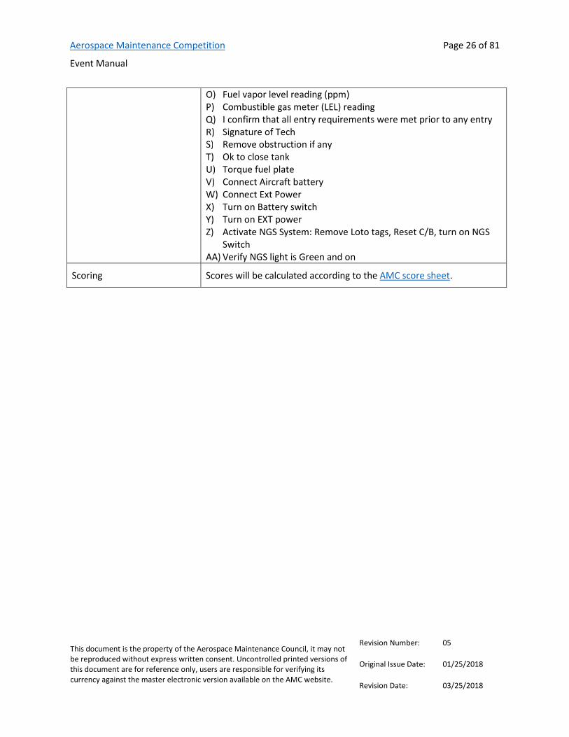
Fuel vapor level reading (ppm) Combustible gas meter (LEL) reading I confirm that all entry requirements were met prior to any entry Signature of Tech Remove obstruction if any Ok to close tank Torque fuel plate Connect Aircraft battery Connect Ext Power
Turn on Battery switch Turn on EXT power Activate NGS System: Remove Loto tags, Reset C/B, turn on NGS
Switch Verify NGS light is Green and on
Scoring Scores will be calculated according to the AMC score sheet.

Aerospace Maintenance Competition
Event Manual
Page 27 of 81
This document is the property of the Aerospace Maintenance Council, it may not be reproduced without express written consent. Uncontrolled printed versions of this document are for reference only, users are responsible for verifying its currency against the master electronic version available on the AMC website.
Revision Number: 05
Original Issue Date: 01/25/2018
Revision Date: 03/25/2018
Event #6 Boroscope—CANCELLED

Aerospace Maintenance Competition
Event Manual
Page 28 of 81
This document is the property of the Aerospace Maintenance Council, it may not be reproduced without express written consent. Uncontrolled printed versions of this document are for reference only, users are responsible for verifying its currency against the master electronic version available on the AMC website.
Revision Number: 05
Original Issue Date: 01/25/2018
Revision Date: 03/25/2018
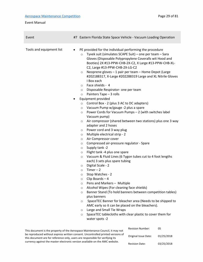
Event #7 Eastern Florida State Space Vehicle - Vacuum Loading Operation
Provided by
Contact(s)/Judge(s) Bill Fletcher, [email protected]
Description This event simulates the loading of a small quantity of a hazardous commodity from a holding tank into a space vehicle flight tank. The individual performing the procedure will be required to don the proper PPE, assemble a mobile fluid transfer station per a detailed procedure and a schematic and transfer 200 grams of a commodity (colored water) from a holding tank to a flight tank using a vacuum loading operation. A command/response protocol (see definition below) must be followed when completing the operation. Upon completion of the fluid transfer all system lines will be evacuated using compressed air (60 seconds) and disassembled from the station. (Note: The Flight Tank does not drain during line evacuation).
The QDs we are using are a push/pull type connector (explain inserting and pushing until it bottoms out and then how they have to push on the collar to get it to release the tubing). One will be available at the event table prior to the event for the technician to look at and operate to familiarize themselves on how it works.
All steps must be completed. There are no provisions for NOT PERFORMING a step or series of steps.
Definition of Command/Response Protocol- a method of communication in such a manner that the command or work instruction is read by one individual (command) and then it is repeated (response) by the person performing that work step as they complete the instruction.
References None
Aerospace Maintenance Competition
Event Manual
Page 29 of 81
This document is the property of the Aerospace Maintenance Council, it may not be reproduced without express written consent. Uncontrolled printed versions of this document are for reference only, users are responsible for verifying its currency against the master electronic version available on the AMC website.
Revision Number: 05
Original Issue Date: 01/25/2018
Revision Date: 03/25/2018
Event #7 Eastern Florida State Space Vehicle - Vacuum Loading Operation
Tools and equipment list • PE provided for the individual performing the procedure o Tyvek suit (simulates SCAPE Suit) – one per team – Sara
Gloves (Disposable Polypropylene Coveralls wit Hood and Booties) 2X #13-PPW-CHB-2X-C2, X Large #13-PPW-CHB-XL-C2, Large #13-PPW-CHB-2X-LG-C2
o Neoprene gloves – 1 pair per team – Home Depot (Large #202188317, X-Large #202288319 Large and XL Nitrile Gloves I Box each
o Face shields - 4 o Disposable Respirator- one per team o Painters Tape – 3 rolls
• Equipment provided o Control Box - 2 (plus 3 AC to DC adapters) o Vacuum Pump w/gauge -2 plus a spare o Power Cords for Vacuum Pumps – 2 (with switches label
Vacuum pump) o Air compressor (shared between two stations) plus one 3 way
adapter and 2 hoses o Power cord and 3 way plug o Multiple electrical strip - 2 o Air Compressor cover o Compressed air-pressure regulator - Spare o Supply tank -2 o Flight tank -4 plus one spare o Vacuum & Fluid Lines (6 Tygon tubes cut to 4 foot lengths
each) 3 sets plus spare tubing o Digital Scale - 2 o Timer – 2 o Stop Watches - 2 o Clip Boards – 4 o Pens and Markers – Multiple o Alcohol Wipes (For cleaning face shields) o Banner Stand (To hold banners between competition tables)
plus banners o SpaceTEC Banner for bleacher area (Needs to be shipped to
AMC early so it can be placed on the bleachers). o Large and Small Tie Wraps o SpaceTEC tablecloths with clear plastic to cover them for
water spots -2
Aerospace Maintenance Competition
Event Manual
Page 30 of 81
This document is the property of the Aerospace Maintenance Council, it may not be reproduced without express written consent. Uncontrolled printed versions of this document are for reference only, users are responsible for verifying its currency against the master electronic version available on the AMC website.
Revision Number: 05
Original Issue Date: 01/25/2018
Revision Date: 03/25/2018
Event #7 Eastern Florida State Space Vehicle - Vacuum Loading Operation
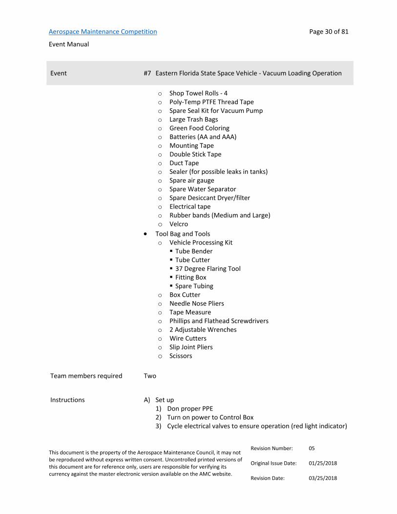
o Shop Towel Rolls - 4 o Poly-Temp PTFE Thread Tape o Spare Seal Kit for Vacuum Pump o Large Trash Bags o Green Food Coloring o Batteries (AA and AAA) o Mounting Tape o Double Stick Tape o Duct Tape o Sealer (for possible leaks in tanks) o Spare air gauge o Spare Water Separator o Spare Desiccant Dryer/filter o Electrical tape o Rubber bands (Medium and Large) o Velcro
• Tool Bag and Tools o Vehicle Processing Kit Tube Bender Tube Cutter 37 Degree Flaring Tool Fitting Box Spare Tubing
o Box Cutter o Needle Nose Pliers o Tape Measure o Phillips and Flathead Screwdrivers o 2 Adjustable Wrenches o Wire Cutters o Slip Joint Pliers o Scissors
Team members required Two
Instructions Set up 1) Don proper PPE 2) Turn on power to Control Box 3) Cycle electrical valves to ensure operation (red light indicator)

Aerospace Maintenance Competition
Event Manual
Page 31 of 81
This document is the property of the Aerospace Maintenance Council, it may not be reproduced without express written consent. Uncontrolled printed versions of this document are for reference only, users are responsible for verifying its currency against the master electronic version available on the AMC website.
Revision Number: 05
Original Issue Date: 01/25/2018
Revision Date: 03/25/2018
Event #7 Eastern Florida State Space Vehicle - Vacuum Loading Operation
4) Verify all valves (manual and electrical) are closed 5) Turn off power to the Control Box 6) Connect Vacuum and Fluid lines as shown in schematic. Note:
all fittings are push lock type. Ensure lines are pushed in all the way. The compressed air line to pressure valve will already be connected.
7) Verify all Vacuum and Fluid lines are connected as shown in schematic.
8) Verify Flight Tank is on digital scale. Evacuate Tank
1) Turn on power to Control Box 2) Start Vacuum Pump 3) Open Vacuum Valve 4) Open Flight Valve 5) Open MV2 6) Evacuate system until vacuum gage reads at least 22 Hg +/- 5 7) Close Vacuum Valve 8) Close Flight Valve 9) Turn off Vacuum pump
Flight Tank Load-Vacuum 1) Turn on digital scale and tare 2) Open Atmospheric Vent Valve 3) Open Supply Valve 4) Open Flight Valve and cycle valve as necessary to meter 200
grams of fluid into Flight Tank - NOTIFY JUDGE WHEN COMPLETE
5) Close all valves (manual and electric)
Note: If Vacuum load was unsuccessful, step 4-System Drain must be completed before restarting step 2-Evacuate Tank
System Drain 1) Verify all valves closed (manual and electric) 2) Verify compressed air regulator set at 20+/-5 psi 3) Open MV3 4) Open MV1 5) Open Atmospheric Vent Valve 6) Open Flight Valve 7) Open Supply Valve 8) Open Pressure Valve

Aerospace Maintenance Competition
Event Manual
Page 32 of 81
This document is the property of the Aerospace Maintenance Council, it may not be reproduced without express written consent. Uncontrolled printed versions of this document are for reference only, users are responsible for verifying its currency against the master electronic version available on the AMC website.
Revision Number: 05
Original Issue Date: 01/25/2018
Revision Date: 03/25/2018
Event #7 Eastern Florida State Space Vehicle - Vacuum Loading Operation
9) Purge all water from system for 60 seconds (use timer provided) Note: FLIGHT TANK DOES NOT DRAIN
10) Close Pressure Valve 11) Close Supply Valve 12) Close Flight Valve 13) Close Atmospheric Vent Valve 14) Close MV1 15) Reduce compressed air regulator to zero 16) Close MV3 17) Open MV2 to vent Flight Tank 18) Open MV1 to vent Supply Tank 19) Close all valves (manual and electric) 20) Turn Power off to Control Box
System Clean up 1) Verify power to vacuum pump and control box is turned off 2) Verify all valves closed 3) Disconnect all hoses between control panel and tanks (both
ends of all 6 hoses must be disconnected)
END OF EVENT
Participants should remove PPE and return it to the PPE staging table
Scoring Scores will be calculated according to the AMC score sheet. Additional penalties may be assessed for each step not completed and for each gram over/under flight tank load target
Aerospace Maintenance Competition
Event Manual
Page 33 of 81
This document is the property of the Aerospace Maintenance Council, it may not be reproduced without express written consent. Uncontrolled printed versions of this document are for reference only, users are responsible for verifying its currency against the master electronic version available on the AMC website.
Revision Number: 05
Original Issue Date: 01/25/2018
Revision Date: 03/25/2018
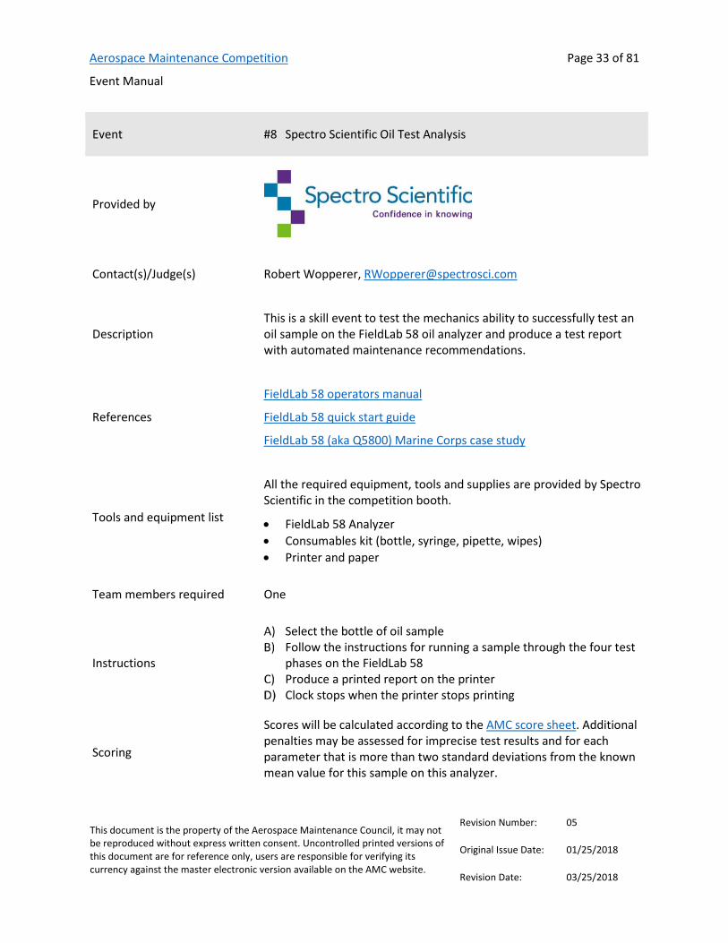
Event #8 Spectro Scientific Oil Test Analysis
Provided by
Contact(s)/Judge(s) Robert Wopperer, [email protected]
Description This is a skill event to test the mechanics ability to successfully test an oil sample on the FieldLab 58 oil analyzer and produce a test report with automated maintenance recommendations.
References
FieldLab 58 operators manual
FieldLab 58 quick start guide
FieldLab 58 (aka Q5800) Marine Corps case study
Tools and equipment list
All the required equipment, tools and supplies are provided by Spectro Scientific in the competition booth.
• FieldLab 58 Analyzer • Consumables kit (bottle, syringe, pipette, wipes) • Printer and paper
Team members required One
Instructions
Select the bottle of oil sample Follow the instructions for running a sample through the four test
phases on the FieldLab 58 Produce a printed report on the printer Clock stops when the printer stops printing
Scoring
Scores will be calculated according to the AMC score sheet. Additional penalties may be assessed for imprecise test results and for each parameter that is more than two standard deviations from the known mean value for this sample on this analyzer.
Aerospace Maintenance Competition
Event Manual
Page 34 of 81
This document is the property of the Aerospace Maintenance Council, it may not be reproduced without express written consent. Uncontrolled printed versions of this document are for reference only, users are responsible for verifying its currency against the master electronic version available on the AMC website.
Revision Number: 05
Original Issue Date: 01/25/2018
Revision Date: 03/25/2018
Event #9 Abaris Training Composite Repair
Provided by
Contact(s)/Judge(s) Corrie Volinkaty, Technical Instructor, [email protected]
Description This skills event is based on an elevated high temperature, vacuum bagged, composite repair scenario.
References Text book titled “Essentials of Advance Composite Fabrication & Repair” Available thru Aviation Supplies & Academics, Inc.’s website www.asa2fly.com
Tools and equipment list Each team will be provided a work packet which includes the Job Card, Repair Ply Material and vacuum bag. All tools & equipment needed to perform this skills event will be provided and reused by all teams including the following items; Vacuum source/hoses/ports, Heatcon Single Zone Bonder/heat blanket/thermocouples, scissors, Stanley Knife, sharpie marker, volt ohm meter, 12-inch scale, circle template, tape dispenser and calculator.
Team members required Two
Instructions Competitors may review the job card in the five minutes preceding the event’s official start time. Arriving at the Composite Skills Event early allows for more time to review Job Card & derive a plan of attack.
The Job Card can be accomplished in any order that is decided by the team, but all sign off blocks must be completed. Non-completed job cards are a frequently-cited penalty for this event so take care to sign off all blocks.
Repair ply material, a rectangle piece of paper, will be used for the repair plies. After drawing a 3”, 4” and 5” circle with the circle template provided, mark the warp direction by drawing a line
Aerospace Maintenance Competition
Event Manual
Page 35 of 81
This document is the property of the Aerospace Maintenance Council, it may not be reproduced without express written consent. Uncontrolled printed versions of this document are for reference only, users are responsible for verifying its currency against the master electronic version available on the AMC website.
Revision Number: 05
Original Issue Date: 01/25/2018
Revision Date: 03/25/2018
within each circle. The short side of the repair material is the warp direction. Once cut out, follow Job Card for proper orientation of each repair ply…a cause of many deductions in the past, the Judge will be watching closely!!
Teams should be familiar with Ohm’s Law when given Voltage, Wattage & solving for Resistance (R = V² ÷ W). This will be used to calculate, measure & document both results on the Job Card. They also need to solve & calculate a resin mix ratio word problem…Example; Based on a given amount of total mixed epoxy resin needed, say 50 grams with a mix ratio 100:35, how many grams of Part A? How many grams of Part B? Teams will clearly write their answers on the Job Card.
Teams should also be familiar with vacuum bag processing. Peel ply, Bleeder, solid film, Breather materials needed for this skills challenge will be pre-cut, clearly marked and reused for all other teams. Once their repair area is vacuumed down they can start the bonder.
After you are done, the judge will give your time to write on the Job Card. Take a breath… & please help clean up and put the table back the way you found it. All cleanup efforts are greatly appreciated.
All teams must understand that these instructions are a general overview of this skills challenge & that there is a lot of detail on the Job Card, that if not followed, can lead to problems and/or unexpected deductions.
Scoring Scores will be calculated according to the AMC score sheet. Additional penalties may be assessed for items missed or a block not signed off on a job card.

Aerospace Maintenance Competition
Event Manual
Page 36 of 81
This document is the property of the Aerospace Maintenance Council, it may not be reproduced without express written consent. Uncontrolled printed versions of this document are for reference only, users are responsible for verifying its currency against the master electronic version available on the AMC website.
Revision Number: 05
Original Issue Date: 01/25/2018
Revision Date: 03/25/2018
Event #10 PPG Aerospace Cockpit and Wing Sealant
Provided by
Contact(s)/Judge(s) Connie Griesemer, Product Support Engineer, PPG, [email protected]
Description This is a three-part event, each consisting of 15 minutes (scored and timed separately). There is a transparencies section and a sealant and sealant application tools section. The transparencies section will require a Surface Seal application and a humpseal repair. The sealant section will require operators to perform fillet sealing applications inside a demo wing. The application tools section will relate to FOD mitigation.
References Technical data sheet for Semco® 1088 Mixer, FlexPak cartridge, Semco® 1250 Battery Gun, and TDS/Application Guide for P/S 815M
Moisture Seal Repair Procedure
Surface Seal Procedure
Tools and equipment list See above
Team members required Five
Instructions See procedures, linked above.
Scoring Scores will be calculated according to the AMC score sheet. Additional penalties may be assessed for any process errors and/or quality concerns based on overall appearance, proper use of vinyl guide strip, blend into existing moisture seal, holes or bubbles, proper sealant mixing, water break free surface, proper coating application and cleanliness.
Aerospace Maintenance Competition
Event Manual
Page 37 of 81
This document is the property of the Aerospace Maintenance Council, it may not be reproduced without express written consent. Uncontrolled printed versions of this document are for reference only, users are responsible for verifying its currency against the master electronic version available on the AMC website.
Revision Number: 05
Original Issue Date: 01/25/2018
Revision Date: 03/25/2018
Event #11 ULTRAX Condition Based Intelligence TM (CBI TM)
Provided by
Contact(s)/Judge(s) Travis Fisher – Corporate Development, 816-595-4472 [email protected]
Dominic Hogan - Director Engineering, 816-595-4463 [email protected]
Description Electrical Analysis & Troubleshooting
References www.ultraxinc.com
www.ultraxinc.com/amc2018
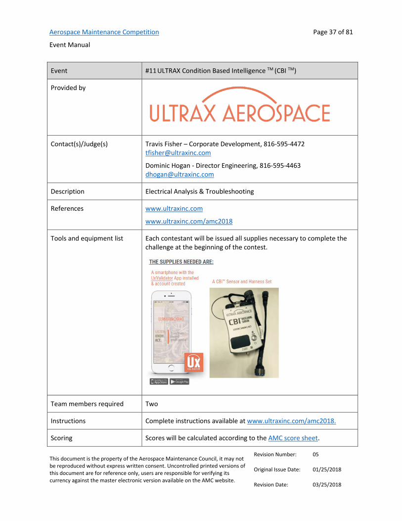
Tools and equipment list Each contestant will be issued all supplies necessary to complete the challenge at the beginning of the contest.
Team members required Two
Instructions Complete instructions available at www.ultraxinc.com/amc2018.
Scoring Scores will be calculated according to the AMC score sheet.
Aerospace Maintenance Competition
Event Manual
Page 38 of 81
This document is the property of the Aerospace Maintenance Council, it may not be reproduced without express written consent. Uncontrolled printed versions of this document are for reference only, users are responsible for verifying its currency against the master electronic version available on the AMC website.
Revision Number: 05
Original Issue Date: 01/25/2018
Revision Date: 03/25/2018
Event #12 Atheer AiR & American Airlines Augmented Reality Pedestal
Provided by
Contact(s)/Judge(s) [email protected]
Description Execute removal/replacement of cockpit console component & record critical information per OEM procedure
References None
Tools and equipment list Screwdriver - common slot
ESDS wrist strap
Cannon Plug Pliers
Voltmeter
Team members required Two
Instructions None
Scoring Scores will be calculated according to the AMC score sheet.

Aerospace Maintenance Competition
Event Manual
Page 39 of 81
This document is the property of the Aerospace Maintenance Council, it may not be reproduced without express written consent. Uncontrolled printed versions of this document are for reference only, users are responsible for verifying its currency against the master electronic version available on the AMC website.
Revision Number: 05
Original Issue Date: 01/25/2018
Revision Date: 03/25/2018
Event #13 Embry-Riddle Precision Measurement
Provided by
Contact(s)/Judge(s) Christopher Piccone, [email protected]
Description Using specified precision measurement instruments technicians will be required to correctly measure engine components and determine whether or not they can be returned to service. This event will test the competitor skills with precision instruments and their dimensional analytical skills from the measurements taken. This event will also test critical thinking skills through technical manual use to identify limits and determine serviceability of given parts. Measurements may include I.D., O.D., clearance between parts, and depth.
References General Handbook (FAA-H-8083-30A) (Chapter 11)
Lycoming Direct Drive Overhaul Manual
Lycoming Direct Drive Illustrated Parts Catalog
Tools and equipment list Outside Micrometer Set
Depth Micrometer
Slide Caliper
T Gauge Set
Small Hole Gauge Set
Bore Gauge

Aerospace Maintenance Competition
Event Manual
Page 40 of 81
This document is the property of the Aerospace Maintenance Council, it may not be reproduced without express written consent. Uncontrolled printed versions of this document are for reference only, users are responsible for verifying its currency against the master electronic version available on the AMC website.
Revision Number: 05
Original Issue Date: 01/25/2018
Revision Date: 03/25/2018
Event #13 Embry-Riddle Precision Measurement
Calculator
Team members required One
Instructions Technicians must verify calibration using standards bars and referencing calibration date on instrument. After verification of equipment components will be measured and measurements recorded. Referencing the applicable dimensional constraints found in the technical manuals the competitors will identify serviceability of the components.
Scoring Scores will be calculated according to the AMC score sheet. Additional penalties may be assessed for failure to verify calibration, damage to measurement instruments or parts, improper handling of measurement instruments or parts, incorrect Measurements & calculations (within a degree of error), incorrect technical manual references, or incorrect serviceability identification.
Aerospace Maintenance Competition
Event Manual
Page 41 of 81
This document is the property of the Aerospace Maintenance Council, it may not be reproduced without express written consent. Uncontrolled printed versions of this document are for reference only, users are responsible for verifying its currency against the master electronic version available on the AMC website.
Revision Number: 05
Original Issue Date: 01/25/2018
Revision Date: 03/25/2018
Event #14 JetBlue University ADS-B Troubleshooting
Provided by
Contact(s)/Judge(s) Andy Kozak, [email protected]
Description Technicians will use modern test equipment, AeroflexIFR 6000 to validate proper operation and reporting to comply with the upcoming 2020 regulations for all aircraft operating in regulated airspace. The technicians will set-up the mock aircraft to be tested and demonstrate proper testing procedures and document results for completion.
References Event overview
Tools and equipment list Electronic Flight Instrument panel set-up with GPS and Encoder simulators to represent a working modern flightdeck.
Team members required Two
Instructions The technician will fill out a task card with reported information from the IFR 6000. See linked event overview, above, for more information.
Scoring Scores will be calculated according to the AMC score sheet.
Aerospace Maintenance Competition
Event Manual
Page 42 of 81
This document is the property of the Aerospace Maintenance Council, it may not be reproduced without express written consent. Uncontrolled printed versions of this document are for reference only, users are responsible for verifying its currency against the master electronic version available on the AMC website.
Revision Number: 05
Original Issue Date: 01/25/2018
Revision Date: 03/25/2018
Event #15 Barfield Fuel Quantity
Provided by
Contact(s)/Judge(s) Victor Bontorno, Director, [email protected]
Lew Wingate, Vice President, GTSE & Dist
Description This timed event will test a team’s ability to troubleshoot and repair a mockup of an aircraft AC capacitance fuel quantity indicating system. The team will be given a problem report, a Barfield DFQ40K Test Set, System and Tank Wall Adapter Cables, a Wiring Diagram and the Procedures used to test, troubleshoot and verify the system. The team will demonstrate the ability to follow the test procedures using the test equipment and comparing recorded test data to find the fault(s). The team will provide the judge with the supporting test data for any fault found and the judge will advise as to course of action to remedy.
References Barfield DFQ40K Test Set information
Product Flyer
Operation Manual
Wiring Diagram
Test Data Sheet
Procedure
Tools and equipment list Barfield DFQ40K Test Set, Adapter Cables, and all necessary replacement parts to correct faults found
Team members required Two

Aerospace Maintenance Competition
Event Manual
Page 43 of 81
This document is the property of the Aerospace Maintenance Council, it may not be reproduced without express written consent. Uncontrolled printed versions of this document are for reference only, users are responsible for verifying its currency against the master electronic version available on the AMC website.
Revision Number: 05
Original Issue Date: 01/25/2018
Revision Date: 03/25/2018
Event #15 Barfield Fuel Quantity
Instructions 1) TIMER a) The Judge will start the timer to begin the event. b) The Team will be responsible for stopping the timer when
finished. 2) BENCH
a) Circuit Breaker i) CAUTION: The Circuit Breaker (CB) must be open before
making/breaking any connections. b) Connections
i) Connectors labeled as J1 and J2 are the System connection (equivalent to Indicator connection).
ii) Connectors labeled as J3 and J4 are the Probes connection (equivalent to Tank Wall connection).
c) Probes i) Are accessible from the rear of bench and require no tools
for replacement. 3) TEST SET
a) The Test Set is already powered ON, initialized and left at the Main Menu.
b) All Ranges and Modes have been pre-set. 4) ADAPTER CABLES
a) The System Adapter Cable P/N 611-00050 is used to test between J1 and J2.
b) The Probes Adapter Cable P/N 611-00051 is used to test at J4. 5) PROCEDURES & TEST DATA SHEET
a) Follow Procedure (84-611-00049-170411-1B) i) The tests sections contained in the procedure MUST be
performed in the order given. ii) If there are any issues with the Insulation tests, there will
not be more than 1 problem. iii) If there are any issues with the Capacitance tests, there
will not be more than 1 problem. iv) The team will provide the judge with the supporting test
data for any fault found and the judge will advise as to course of action to remedy.
b) Test Data Sheet i) All measurements must be recorded on the Test Data
Sheet (64-611-00049-170228-4B) as proof of work.

Aerospace Maintenance Competition
Event Manual
Page 44 of 81
This document is the property of the Aerospace Maintenance Council, it may not be reproduced without express written consent. Uncontrolled printed versions of this document are for reference only, users are responsible for verifying its currency against the master electronic version available on the AMC website.
Revision Number: 05
Original Issue Date: 01/25/2018
Revision Date: 03/25/2018
Event #15 Barfield Fuel Quantity
ii) The Team will be responsible for recording their time on the Test Data Sheet.
Scoring Scores will be calculated according to the AMC score sheet.
Aerospace Maintenance Competition
Event Manual
Page 45 of 81
This document is the property of the Aerospace Maintenance Council, it may not be reproduced without express written consent. Uncontrolled printed versions of this document are for reference only, users are responsible for verifying its currency against the master electronic version available on the AMC website.
Revision Number: 05
Original Issue Date: 01/25/2018
Revision Date: 03/25/2018
Event #16 Barfield Pitot Static
Provided by
Contact(s)/Judge(s) Curtis Lamb, Sales Director, [email protected]
Richard Floyd, Senior Engineer
Desi Diaz, GSTE Shop Manager
Description This competition is designed to test the skills of each participating team in their understanding of and ability to troubleshoot an aircraft Pitot-Static system. Barfield recommends participants fully understand a basic aircraft Pitot-Static system and potential issues that could be found. The faults found during this procedure will test this knowledge.
References DPS 1000 User Instruction Manual
Tools and equipment list See procedure, linked below
Team members required Two
Instructions See procedures (84-611-00052-150412-5)
Scoring Scores will be calculated according to the AMC score sheet.
Aerospace Maintenance Competition
Event Manual
Page 46 of 81
This document is the property of the Aerospace Maintenance Council, it may not be reproduced without express written consent. Uncontrolled printed versions of this document are for reference only, users are responsible for verifying its currency against the master electronic version available on the AMC website.
Revision Number: 05
Original Issue Date: 01/25/2018
Revision Date: 03/25/2018
Event #17 FedEx Express Turbine Engine
Provided by
Contact(s)/Judge(s) Mark Holsapple, [email protected]
Description This event will test the technician’s ability to remove and install the Pneumatic Drive Unit (PDU) unit on a Pratt and Whitney JT9D turbofan engine.
References None
Tools and equipment list 1 ea. 100-500 in. lbs. torque wrench 3/8 in. drive
1 ea. 1/4 in. drive standard socket set p/n 110TMDY
1 ea. 1/4 in. drive ratchet
1 ea. 6 in. extension ¼ in. drive p/n TMXK60
1 ea. 14 in. extension ¼ in. drive p/n TMXK140
1 ea. 3/8 in. drive standard socket set p/n 211FY
1 ea. 3/8 in. drive ratchet
1 ea. 6 in. extension 3/8 in. drive p/n FXK6
1 ea. 11 in. extension 3/8 in. drive p/n FXK11
1 ea. crows feet wrenches 3/8 in. drive @ 9/16 in. and 5/8 in. and 11/16 in.
1 ea. Snap-On ratcheting screw driver with phillips APEX bit
1 ea. cannon plug pliers
1 ea. safety wire pliers
1 set of standard 12 point combination wrenches p/n OEX710

Aerospace Maintenance Competition
Event Manual
Page 47 of 81
This document is the property of the Aerospace Maintenance Council, it may not be reproduced without express written consent. Uncontrolled printed versions of this document are for reference only, users are responsible for verifying its currency against the master electronic version available on the AMC website.
Revision Number: 05
Original Issue Date: 01/25/2018
Revision Date: 03/25/2018
Event #17 FedEx Express Turbine Engine
Team members required Three
Instructions Pneumatic Drive Unit (PDU) – Removal/Installation Access the pneumatic drive unit through the left fan cowl door. Removal
1) Remove lockwire, screws, and washers attaching flexible shaft to PDU and remove shaft.
2) Disconnect three hoses from pneumatic drive unit and remove unions and packings. Discard packings
3) Disconnect electrical connector from PDU and install protective caps on connector and PDU receptacle and ports.
4) Remove coupling connecting duct to PDU. 5) Remove bolts, nuts, and washers attaching PDU to brackets. 6) Remove PDU from fan case and install protective caps on duct
and PDU port. Installation
1) Remove protective caps from PDU (1) and flexible duct. Apply lubricant Material No. P06-013 to inside surface of coupling and position on end of flexible duct.
2) Position pneumatic drive unit on brackets, and install bolts (6) in upper forward and aft bracket holes.
3) Install and tighten bolt (6) and washer (7) in lower forward bracket fingertight.
4) Install washers (7) and nuts (8) on bolts in upper and lower aft brackets and TORQUE all nuts and lower forward bolt to between 160 and 190 lbf.in. (1.8 and 2.14 m. daN).
5) Install coupling (2) on PDU and duct flanges.
[Verbal (6) thru (9)]
6) Apply lubricant, Material No.P06-017, to threads of unions. 7) Install union (11) with new packing (12) in PDU. TORQUE union
(11) to between 125 and 140 lbf. in. (1.41 and 1.58 m. daN). 8) Install union (5) with new packing (4) in PDU. TORQUE union
(5) to between 115 and 130 lbf.in. (1.29 and 1.47 m. daN). 9) Install union (3) with new packing (13) in PDU and TORQUE to
between 90 and 100 lbf.in. (1.02 and 1.13 m. daN). 10) Connect electrical connector DS304 to PDU and tighten
fingertight plug one-eighth turn
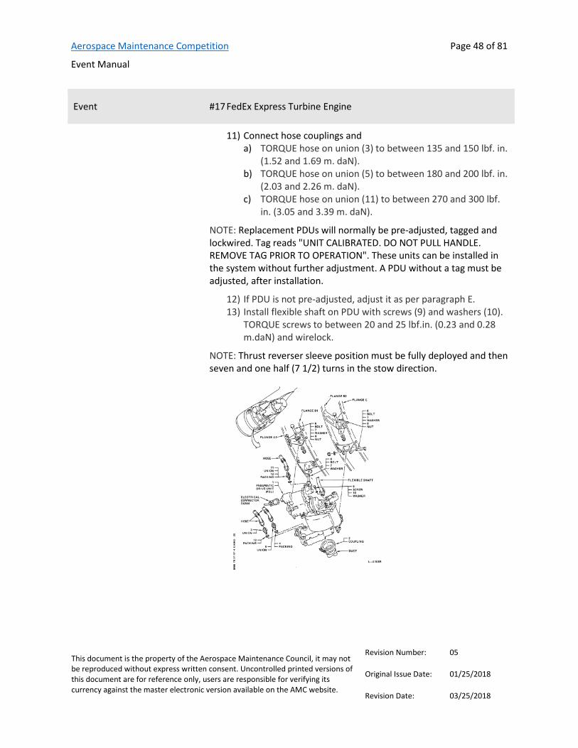
Aerospace Maintenance Competition
Event Manual
Page 48 of 81
This document is the property of the Aerospace Maintenance Council, it may not be reproduced without express written consent. Uncontrolled printed versions of this document are for reference only, users are responsible for verifying its currency against the master electronic version available on the AMC website.
Revision Number: 05
Original Issue Date: 01/25/2018
Revision Date: 03/25/2018
Event #17 FedEx Express Turbine Engine
11) Connect hose couplings and a) TORQUE hose on union (3) to between 135 and 150 lbf. in.
(1.52 and 1.69 m. daN). b) TORQUE hose on union (5) to between 180 and 200 lbf. in.
(2.03 and 2.26 m. daN). c) TORQUE hose on union (11) to between 270 and 300 lbf.
in. (3.05 and 3.39 m. daN).
NOTE: Replacement PDUs will normally be pre-adjusted, tagged and lockwired. Tag reads "UNIT CALIBRATED. DO NOT PULL HANDLE. REMOVE TAG PRIOR TO OPERATION". These units can be installed in the system without further adjustment. A PDU without a tag must be adjusted, after installation.
12) If PDU is not pre-adjusted, adjust it as per paragraph E. 13) Install flexible shaft on PDU with screws (9) and washers (10).
TORQUE screws to between 20 and 25 lbf.in. (0.23 and 0.28 m.daN) and wirelock.
NOTE: Thrust reverser sleeve position must be fully deployed and then seven and one half (7 1/2) turns in the stow direction.

Aerospace Maintenance Competition
Event Manual
Page 49 of 81
This document is the property of the Aerospace Maintenance Council, it may not be reproduced without express written consent. Uncontrolled printed versions of this document are for reference only, users are responsible for verifying its currency against the master electronic version available on the AMC website.
Revision Number: 05
Original Issue Date: 01/25/2018
Revision Date: 03/25/2018
Event #17 FedEx Express Turbine Engine
Scoring Scores will be calculated according to the AMC score sheet. Additional penalties may be assessed for failure to complete the task, failure to place PDU on table and simulate packing change, failure to show judge torque on wrench before proceeding, failure to install or secure mount bolts, failure to install, secure or torque Lines and B Nuts, incorrect or sloppy safety wiring.
Aerospace Maintenance Competition
Event Manual
Page 50 of 81
This document is the property of the Aerospace Maintenance Council, it may not be reproduced without express written consent. Uncontrolled printed versions of this document are for reference only, users are responsible for verifying its currency against the master electronic version available on the AMC website.
Revision Number: 05
Original Issue Date: 01/25/2018
Revision Date: 03/25/2018
Event #18 Indian Hills Community College Magneto
Provided by Indian Hills Community College
Contact(s)/Judge(s) Terry Dunkin, [email protected], 641-683-4252
Description This event will require the contestant to internally time a magneto, test for operation and install on a reciprocating engine.
The contestant will be supplied a magneto, test and timing equipment and the tools necessary to complete the challenge.
The magnetos that will be used are slick magnetos by Champion Aerospace. The service information necessary for the internal timing of the magneto will be furnished to the contestant at the event.
The engine that the magneto is to be installed is a Continental 0200A. Information for installation of the magneto can be found in the 0200 service manual. The timing requirement will be found in the Engine Type Certificate Data Sheet. All necessary information for completion of this challenge will be supplied to the contestant at the event.
References Type Certificate Data Sheet
Tools and equipment list None
Team members required Two
Note: One competitor will inspect and internally time the magneto. At the judge’s signal, the second competitor may assist installing the magneto to the engine.
Aerospace Maintenance Competition
Event Manual
Page 51 of 81
This document is the property of the Aerospace Maintenance Council, it may not be reproduced without express written consent. Uncontrolled printed versions of this document are for reference only, users are responsible for verifying its currency against the master electronic version available on the AMC website.
Revision Number: 05
Original Issue Date: 01/25/2018
Revision Date: 03/25/2018
Event #18 Indian Hills Community College Magneto
Instructions Inspect magneto for internal condition: Cursory inspection only. Look for loose wires improper assembly etc.
Internally time the magneto, follow manufacturers information. Set Egap, Points and distributor.
Install your magneto on the test stand, run to assure proper operation.
Validate magneto to engine timing with the aircraft Type Certificate Data Sheet.
Install your serviced magneto to the engine and check the timing. When you have completed the installation of the magneto on the
engine, you must turn on the light on your magneto test bench. This will signal for your time to stop.
Scoring Scores will be calculated according to the AMC score sheet. Additional penalties may be assessed for any portion not completed, improper inspection of points, rotor, distributor block or condenser wire, incorrect internal timing, failure to follow service information, failure to validate magneto timing or improper installation.

Aerospace Maintenance Competition
Event Manual
Page 52 of 81
This document is the property of the Aerospace Maintenance Council, it may not be reproduced without express written consent. Uncontrolled printed versions of this document are for reference only, users are responsible for verifying its currency against the master electronic version available on the AMC website.
Revision Number: 05
Original Issue Date: 01/25/2018
Revision Date: 03/25/2018
Event #19 Boeing Cable Rigging
Provided by
Contact(s)/Judge(s) George Thompson, Boeing Seattle Flight Test, [email protected]
Joseph Fancella III, Boeing 777 AMT Pre-Flight & Delivery
Description After first flight the aileron cable rig was found to be out of tolerance. Re-rigging is required. Use the following instructions to rig the cables. Team members must complete re-rigging of cables AA & AB.
References None
Tools and equipment list None
Team members required Two
Instructions Warning: Check and clear aircraft and flight controls before turning on hydraulics.
Turn on both A&B system hydraulic switches, cycle ailerons check and Install the rig pins in the captain’s wheel and the Aileron control quadrant.
Warning: Hydraulics systems must be deactivated prior to the start of any rigging operations.
Turn off and deactivate both A&B systems Hydraulics by pulling the Circuit breaker for A & B system and installing the lock out collars.
Select the correct riser for 3/32” Dia. cable being rigged per the tensiometer calibration sheet provided. Use the tension values in table 1-3 Cable Rigging Tension page 2 and the tensiometer calibration sheet. Using the cable clamps adjust the cable tension to the correct value +5 / -15 lbs. for 70 F outside ambient temperature. Warning: Check and clear aircraft and flight controls before turning on hydraulics.
Aerospace Maintenance Competition
Event Manual
Page 53 of 81
This document is the property of the Aerospace Maintenance Council, it may not be reproduced without express written consent. Uncontrolled printed versions of this document are for reference only, users are responsible for verifying its currency against the master electronic version available on the AMC website.
Revision Number: 05
Original Issue Date: 01/25/2018
Revision Date: 03/25/2018
Event #19 Boeing Cable Rigging
Remove Rig Pins. Reset Circuit breakers for the A&B system hydraulics Turn on A&B system hydraulic switches cycle the captain’s wheel,
5 times. Note: Operate captain’s wheel gently and smoothly when cycling and returning to neutral.
Recheck rig load (table 1-3) of each cable and free insertion and removal of appropriate rig pins, if good turn off hydraulic and safety turnbuckles per Figure 5. Lock clips shall not be reused. The paint on the clips provides a means for determining that the clips have not been previously used.
No more than 3 threads may show beyond turnbuckel body. Align the slit in the barrel with the slot in the cable terminal, insert the straight end of the lock clip into the aperture formed by the aligned slots, Figure 5 View B, Bring hook end of the lock clip over the hole in the center of the turnbuckle barrel and seat the hook loop into the hole by applying pressure to the hook shoulder. Repeat these steps to lock the opposite end of the turnbuckle. Both locking clips may be inserted in the same turnbuckle barrel hole, Figure 5 View C, or they may be inserted in the opposite holes, Figure 5 View D and Figure 5 View E.
Examine both locking clips for proper engagement of the hook lip by a slight pull in the disengaging direction without the use of any tools (Figure 5 View C), and by visual examination to make certain that the hook lip has engaged the interior of the turnbuckle body (Figure 5 View E). Rotate the rod ends to assure that the locking clips are properly installed. Lock clips shall not be reused.
Using the push rod adjust the aileron to align with the index mark and hand tighten lock nut.
Scoring Scores will be calculated according to the AMC score sheet.
Aerospace Maintenance Competition
Event Manual
Page 54 of 81
This document is the property of the Aerospace Maintenance Council, it may not be reproduced without express written consent. Uncontrolled printed versions of this document are for reference only, users are responsible for verifying its currency against the master electronic version available on the AMC website.
Revision Number: 05
Original Issue Date: 01/25/2018
Revision Date: 03/25/2018
Event #20 American Airlines APU Burner Can
Provided by
Contact(s)/Judge(s) Jim Gentry, B-737 Supervisor Aircraft Maintenance, American Airlines, [email protected]
Glen Phillips, Supervisor, APU and Wiring Center, [email protected]
Description Remove and Replace MD80 APU Combustion Chamber – Packing. Competitors will show inspector torques and return to zero after usage.
References IPC of APU: MD80 AMM 49-20-01-201
Tools and equipment list None
Team members required Two
Instructions General 1) The combustion chamber liner is located inside the
combustion chamber cap on the APU right side. Access is through the APU right access door.
Remove Combustion Chamber assembly and replace packing 1) Cut safety wire on igniter plug lead and igniter plug. 2) Disconnect igniter plug lead from igniter plug. (Figure 201) 3) Disconnect fuel line from atomizer. (Figure 201) 4) Disconnect combustion chamber drain line from fitting in
combustion chamber cap. (Figure 201) 5) Remove safety wire from clamp on combustion chamber cap. 6) Remove clamp that attaches combustion chamber cap to
combustion chamber. 7) Remove combustion chamber assembly.
Aerospace Maintenance Competition
Event Manual
Page 55 of 81
This document is the property of the Aerospace Maintenance Council, it may not be reproduced without express written consent. Uncontrolled printed versions of this document are for reference only, users are responsible for verifying its currency against the master electronic version available on the AMC website.
Revision Number: 05
Original Issue Date: 01/25/2018
Revision Date: 03/25/2018
Event #20 American Airlines APU Burner Can
8) Remove and replace combustion chamber cap packing and use supplied lube.
Reinstall Combustion Chamber assembly 1) Carefully install combustion chamber assembly into the
combustion chamber. 2) Rotate combustion chamber liner and cap until igniter plug is
on top vertical centerline of combustion chamber, drain fitting is on bottom vertical centerline of combustion chamber (Electrical connector and combustion chamber drain line must line up with mating connections).
3) Install combustion chamber coupling clamp but do not tighten.
4) Connect igniter plug lead to igniter plug. (Figure 201) 5) Connect fuel line to atomizer. Torque fuel line to 135 to 150
inch-pounds 6) Install combustion chamber drain line and securely tighten. 7) Tighten combustion chamber coupling clamp to 50 to 70 inch-
pounds and safety wire. 8) Safety wire igniter lead cap and igniter bolts.
Scoring Scores will be calculated according to the AMC score sheet.

Aerospace Maintenance Competition
Event Manual
Page 56 of 81
This document is the property of the Aerospace Maintenance Council, it may not be reproduced without express written consent. Uncontrolled printed versions of this document are for reference only, users are responsible for verifying its currency against the master electronic version available on the AMC website.
Revision Number: 05
Original Issue Date: 01/25/2018
Revision Date: 03/25/2018
Event #21 Pratt & Whitney Geared Turbo Fan Engine
Provided by
Contact(s)/Judge(s) Mr. John Koza – P&W Flight Safety Investigations, [email protected]
Mr. Del Laughery – P&W Customer Training
Description Odd-numbered teams will inspect the oil tank for FOD, and remove FOD if present according to PW1100G-JM Engine Task Even-numbered teams will remove and install cylinder spark plugs according to PW R-985 Wasp Jr. Task
References PW1100G-JM Engine Task PW R-985 Wasp Jr. Task
Tools and equipment list See referenced tasks, linked above.
Team members required Two
Instructions See referenced tasks, linked above.
Scoring Scores will be calculated according to the AMC score sheet. Additional penalties may be assessed for items described in referenced tasks, linked above.
Aerospace Maintenance Competition
Event Manual
Page 57 of 81
This document is the property of the Aerospace Maintenance Council, it may not be reproduced without express written consent. Uncontrolled printed versions of this document are for reference only, users are responsible for verifying its currency against the master electronic version available on the AMC website.
Revision Number: 05
Original Issue Date: 01/25/2018
Revision Date: 03/25/2018
Event #22 W.L. Gore & Associates, Inc. Dry Sealant Panel Installation
Provided by
Contact(s)/Judge(s) GORE™ SKYFLEX™ Aerospace Materials Team:
Jack Penick, Application Engineer [email protected]
Jon Jacobs, Application Engineer [email protected]
Gerhard Burmann, Application Engineer [email protected]
Description This task will include D-Nose Leading Edge and Access Panel installation using GORE SKYFLEX Aerospace Materials
References D-Nose - Installation Guide and Link to video for Installing Flat Tapes on D-Nose: Installation Guide Tapes
Video Surface Protection - D-Nose
Access Panel - Installation Guide and Link to video for Installing Gaskets on Access Panel: Installation Guide Gaskets
Video Environmental Sealant - Gasket
Tools and equipment list Scissors – Link to Scissors
Nylon Hole Awl – Link to Awl
Torque Wrench – One per team
Drill – One per team
Rags
Team members required Three

Aerospace Maintenance Competition
Event Manual
Page 58 of 81
This document is the property of the Aerospace Maintenance Council, it may not be reproduced without express written consent. Uncontrolled printed versions of this document are for reference only, users are responsible for verifying its currency against the master electronic version available on the AMC website.
Revision Number: 05
Original Issue Date: 01/25/2018
Revision Date: 03/25/2018
Event #22 W.L. Gore & Associates, Inc. Dry Sealant Panel Installation
Instructions D-Nose LEADING EDGE: 1) Find 700 Series GORETM SKYFLEXTM Aerospace Tapes- Part
Number GSC-21-95159-024 and ensure within shelf life. 2) Ensure Spar and D-Nose clean and free of debris 3) Apply GORETM SKYFLEXTM Aerospace Tapes on Leading Edge
Spar using 4 pieces of tape cut to length with scissors. The first piece should be applied along the top and the second along the bottom. Finally apply two shorter pieces to the radius and ensure 3-5mm overlap on top and bottom pieces – Figure 1.
4) See Installation Guide for Tapes and watch video in References.
5) Poke holes for each fastener in tape material with Nylon Hole Awl
6) Install Leading Edge Profile over Spar 7) Use provided drill (set to lowest torque setting) to seat each of
the 18 fasteners using a staggered pattern. 8) Use provided torque wrench to tighten each fastener to 25
in·lbs using a staggered pattern

Aerospace Maintenance Competition
Event Manual
Page 59 of 81
This document is the property of the Aerospace Maintenance Council, it may not be reproduced without express written consent. Uncontrolled printed versions of this document are for reference only, users are responsible for verifying its currency against the master electronic version available on the AMC website.
Revision Number: 05
Original Issue Date: 01/25/2018
Revision Date: 03/25/2018
Event #22 W.L. Gore & Associates, Inc. Dry Sealant Panel Installation
Figure 1 - D-Nose Tape Application Area
Team 1 Side
Team 2 Side

Aerospace Maintenance Competition
Event Manual
Page 60 of 81
This document is the property of the Aerospace Maintenance Council, it may not be reproduced without express written consent. Uncontrolled printed versions of this document are for reference only, users are responsible for verifying its currency against the master electronic version available on the AMC website.
Revision Number: 05
Original Issue Date: 01/25/2018
Revision Date: 03/25/2018
Event #22 W.L. Gore & Associates, Inc. Dry Sealant Panel Installation
ACCESS PANEL: 1) Find 720 Series GORETM SKYFLEXTM Aerospace Gaskets Part
Number GSC-21-96704-027 and ensure within shelf life. 2) Ensure Access Panel and Frame clean and free of debris 3) Apply GORETM SKYFLEXTM Aerospace Gaskets on
Polycarbonate Panel 1 shown in Figure 2 – Carefully Align fastener holes in gasket with those on panel.
4) See Installation Guide for Gaskets and watch video link in References.
5) Install Panel in Opening 6) Use provided drill (set to lowest torque setting) to seat each of
the 20 fasteners using a staggered pattern. 7) Use provided torque wrench to tighten each fastener to 25
in·lbs using a staggered pattern
Figure 2 - Gasket and Polycarbonate Access Panel
Scoring Scores will be calculated according to the AMC score sheet. Additional penalties may be assessed for improper tape or gasket alignment.

Aerospace Maintenance Competition
Event Manual
Page 61 of 81
This document is the property of the Aerospace Maintenance Council, it may not be reproduced without express written consent. Uncontrolled printed versions of this document are for reference only, users are responsible for verifying its currency against the master electronic version available on the AMC website.
Revision Number: 05
Original Issue Date: 01/25/2018
Revision Date: 03/25/2018
Event #23 Alaska Airlines External Power Receptacle Event
Provided by
Contact(s)/Judge(s) Robert A. Long, Line/Shop Aircraft Technician, [email protected]
Ernest Yeun, Senior Engineer/AOG Engineer, [email protected]
Duane Bailey, Senior Technical Service Specialist
Ken Pitt, Engineer
Description Competitors will evaluate a discrepancy provided on a logbook sheet and determine steps for corrective action. Competitors will utilize tools to complete the task the complete appropriate paperwork.
References Task Summary
Simulator Aircraft Maintenance Manual
Equipment Inspection flashlight, screw driver, wrench – hex 1/8 inch and 3/16 inch, wear gage, safety tags
Team members required Two
Instructions Identify the aircraft and aircraft type you are tasked to work on Understand the discrepancy provided on the logbook sheet and
determine planned action for corrective action

Aerospace Maintenance Competition
Event Manual
Page 62 of 81
This document is the property of the Aerospace Maintenance Council, it may not be reproduced without express written consent. Uncontrolled printed versions of this document are for reference only, users are responsible for verifying its currency against the master electronic version available on the AMC website.
Revision Number: 05
Original Issue Date: 01/25/2018
Revision Date: 03/25/2018
Event #23 Alaska Airlines External Power Receptacle Event
Identify the appropriate sections of the Simulated Aircraft Structure (SAS) Maintenance Manual to accomplish corrective maintenance action and associated Task Cards
Identify components, determine effectivities, utilize tools, hardware, technical data and standard aircraft maintenance practices to complete tasks
Complete logbook entry filling in required areas with appropriate information
Consider completed task on SAS Simulator same as completed task on live aircraft
Tool collection and accountability Foreign object debris (FOD) survey within work location
Document completion and task card completion
Scoring Scores will be calculated according to the AMC score sheet. Additional penalties may be assessed as provided for in the Alaska Skills Time Sheet.

Aerospace Maintenance Competition
Event Manual
Page 63 of 81
This document is the property of the Aerospace Maintenance Council, it may not be reproduced without express written consent. Uncontrolled printed versions of this document are for reference only, users are responsible for verifying its currency against the master electronic version available on the AMC website.
Revision Number: 05
Original Issue Date: 01/25/2018
Revision Date: 03/25/2018
Event #24 Nida Corporation Power Troubleshooting
Provided by
Contact(s)/Judge(s) Kevin Gulliver, [email protected]
Description This event challenges the aircraft maintenance technician’s ability to troubleshoot basic aircraft power distribution systems. Contestants will be provided schematics, system descriptions and operational procedures to troubleshoot generic single engine and multi-engine power distribution systems. Scores will be based on the speed and accuracy of finding the system faults.
References Detailed contest material will be available March 1 at www.nida.com/amc and will also be provided at the orientation.
Tools and equipment list Multi-meters will be provided; however, personal multi-meters are authorized for use during the event.
Team members required Two
Instructions Single Engine Power Distribution System Troubleshooting 1) System will be operationally ready with no faults. 2) Review the pilot “write up” on the discrepancy sheet. 3) Request the first fault insertion from the judge. 4) Determine the most probable cause of the fault and the
recommended repair. 5) Sign off the pilot “write up” with your conclusion. 6) Repeat Steps 2 through 5 until all single engine aircraft faults
are completed. Only one fault will be inserted at a time. Multi-Engine Aircraft Power Distribution System Troubleshooting
1) Move to the multi-engine training panel

Aerospace Maintenance Competition
Event Manual
Page 64 of 81
This document is the property of the Aerospace Maintenance Council, it may not be reproduced without express written consent. Uncontrolled printed versions of this document are for reference only, users are responsible for verifying its currency against the master electronic version available on the AMC website.
Revision Number: 05
Original Issue Date: 01/25/2018
Revision Date: 03/25/2018
Event #24 Nida Corporation Power Troubleshooting
2) Repeat Steps 2 – 6 above until all multi-engine aircraft faults are completed
3) Finish your paperwork and tell the judge to stop the clock.
Scoring Scores will be calculated according to the AMC score sheet. Additional penalties may be assessed for incorrect answers or unfinished scenarios.

Aerospace Maintenance Competition
Event Manual
Page 65 of 81
This document is the property of the Aerospace Maintenance Council, it may not be reproduced without express written consent. Uncontrolled printed versions of this document are for reference only, users are responsible for verifying its currency against the master electronic version available on the AMC website.
Revision Number: 05
Original Issue Date: 01/25/2018
Revision Date: 03/25/2018
Event #25 Boeing Fiber Optics
Provided by
Contact(s)/Judge(s) Greg Steele, 737 Renton Preflight, [email protected]
Donald M. Rogerson
Description The MULTIMODE FIBER OPTIC LIGHT LOSS EVENT has two parts: 1) complete a practical light loss test on a fiber optic bundle and 2) answer test questions.
References 570XL 850/1300nm LED Source Brochure
560XL Fiber Optic Power Meter Datasheet
Tools and equipment list None
Team members required Two
Instructions PART 1: On your board you will have two reference cables that need to be mated to the light source and power meter. The ends with the ST connectors are to be mated to the meters. The other end of these cables are the LC connectors which is a push-pull connector that utilizes a retaining tab latch mechanism. There will be a fiber optic duplex bundle (cable under test) with LC connector adaptors as well as a dust cap container. Channel A can be identified with its RED heat shrink. Channel B can be identified by its BLUE heat shrink. All measurements for this event will be required to be performed at the 850nm wavelength only. Whenever link loss tests are performed on fiber optic networks or cables under test, the results will be displayed on the meter with a readout in “db”. The following picture shows the initial setup that you will find on you table for this fiber optic light loss event.

Aerospace Maintenance Competition
Event Manual
Page 66 of 81
This document is the property of the Aerospace Maintenance Council, it may not be reproduced without express written consent. Uncontrolled printed versions of this document are for reference only, users are responsible for verifying its currency against the master electronic version available on the AMC website.
Revision Number: 05
Original Issue Date: 01/25/2018
Revision Date: 03/25/2018
Event #25 Boeing Fiber Optics
1) Turn on power to both the 570XL LED source and the 560XL power meter and remove dust caps. Ensure the 570XL LED light source and the 560XL power meter are both set to 850nm wavelength. On the 560XL power meter, verify dbm is displayed. Remove dust caps from one end of each of the (2) reference cables. Place the caps in the cap storage container. Clean and mate the (2) reference cables to the 570XL LED source (850nm interface) and the 560XL power meter.
2) Take one of your LC duplex adapters, remove all of the dust caps and place them in the dust cap storage container. Remove the dust cap from one of the reference cables and place it in the storage container. Next clean the reference cable LC connector with the green cartridge cleaner and immediately insert it into one half of the LC duplex adapter until you hear an audible click.
3) Remove dust caps from the second reference cable and place it in the cap storage container. Clean this LC connector and then insert it into the LC duplex adaptor so that the LC connectors are mated end face to end face.

Aerospace Maintenance Competition
Event Manual
Page 67 of 81
This document is the property of the Aerospace Maintenance Council, it may not be reproduced without express written consent. Uncontrolled printed versions of this document are for reference only, users are responsible for verifying its currency against the master electronic version available on the AMC website.
Revision Number: 05
Original Issue Date: 01/25/2018
Revision Date: 03/25/2018
Event #25 Boeing Fiber Optics
4) Record the displayed output power of the 560XL optic power meter: _______________dbm
5) Now that you have recorded the power received in step 4, the reference cable loss can now be recorded as a reference measurement (optional) or it may be “zeroed out”(preffered). To zero out the meter, press and hold the (db/dbm) key on the 560XL power meter for approximately 3 seconds until the small ”r” annunciator appears in the bottom R/H corner and the display reads 0.00db.
6) Remove all the dust caps from the second LC duplex adapter and place them in the dust cap container. Now you are ready to perform optical measurements on the “cable under test”. With power still applied to the 560XL power meter and the 570XL LED light source, remove one of the reference cable LC connectors from the LC duplex adaptor and clean with the green cartridge cleaner. Once clean, insert it into the LC duplex adaptor until you hear an audible click.
7) Remove both dust caps off of the channel A (RED) LC connectors of the cable under test and place them in the dust cap container. Clean both the LC connectors and then insert them into the LC duplex adaptors so that both LC connectors of the reference cables and the cable under test are mated end face to end face.
8) Repeat the above procedure for channel B (BLUE) of the cable under test by cleaning the LC connectors and inserting them next to channel A (RED) in the same half of the duplex adaptors. Use the cap container and clean when necessary to avoid any penalties. METER PASS/FAIL CRITERIA: -2db OR LESS FOR A PASS/ACCEPTABLE GREATER than -2db IS A FAIL/REJECT For example, a reading of -1.95db would be a pass/accept and a reading of -2.1db would be a fail/reject.

Aerospace Maintenance Competition
Event Manual
Page 68 of 81
This document is the property of the Aerospace Maintenance Council, it may not be reproduced without express written consent. Uncontrolled printed versions of this document are for reference only, users are responsible for verifying its currency against the master electronic version available on the AMC website.
Revision Number: 05
Original Issue Date: 01/25/2018
Revision Date: 03/25/2018
Event #25 Boeing Fiber Optics
9) Read and record the optical performance/light loss of channel A (RED) ______________db. ACCEPT ___________ REJECT ________
10) Remove both reference cable LC connectors from the test adaptors, clean, and mate them with channel B (BLUE) in both test adaptors.
11) Read and record the optical performance/light loss of channel b (BLUE) _____________db. ACCEPT ___________ REJECT ________
12) MUST BE COMPLETED: Remove ALL LC connectors from test adaptors and clean them, place ALL dust caps back on ALL connections. Put ALL dust caps back in both your test adaptors and place them neatly in there storage area. Turn off both meters, then clean and cap ALL cables and cap the meters also.
13) Once finished with step 12, tell your judge “I AM FINISHED” to stop the clock.
When you are complete with the PART 1 PRACTICAL you may now begin the PART 2 QUESTIONS that will be provided at the competition.
Scoring Scores will be calculated according to the AMC score sheet. Additional penalties may be assessed for damaging a fiber optic cable or connector, for each time a fiber optic connector is not cleaned on the green reel cleaner after a dust cap is removed or when an LC connector is removed from the test adapter, when a judge provides assistance, or for incorrect answers.

Aerospace Maintenance Competition
Event Manual
Page 69 of 81
This document is the property of the Aerospace Maintenance Council, it may not be reproduced without express written consent. Uncontrolled printed versions of this document are for reference only, users are responsible for verifying its currency against the master electronic version available on the AMC website.
Revision Number: 05
Original Issue Date: 01/25/2018
Revision Date: 03/25/2018
Event #26 Aircraft Maintenance Technicians Association Charles E. Taylor Exam
Provided by Aircraft Maintenance Technicians Association
Contact(s)/Judge(s) Ken MacTiernan, [email protected]
Description This event will consist of multiple choice questions relating to Charles E. Taylor’s life and pioneers of aviation maintenance.
References “Charles E. Taylor 1868 – 1956 The Wright Brothers Mechanician” written by Howard R. DuFour with Peter J. Unitt, available on Amazon or at http://www.lulu.com/shop/howard-dufour-and-peter-unitt/charles-e-taylor-1868-1956-the-wright-brothers-mechanician/paperback/product-21047239.html.
“Pioneer Mechanics in Aviation” written by Giacinta Bradley Koontz, print version available at https://www.lulu.com/shop/view-cart.ep. Electronic version available at https://www.amazon.com/dp/B079FN8P7C/ref=sr_1_1?s=digital-text&ie=UTF8&qid=1517327320&sr=1-1&keywords=pioneer+mechanics+in+aviation
Tools and equipment list None
Team members required One
Instructions Each designated team member will sit for a timed, written exam.
Scoring Scores will be calculated according to the AMC score sheet. Additional penalties will be assessed for each wrong answer.
Aerospace Maintenance Competition
Event Manual
Page 70 of 81
This document is the property of the Aerospace Maintenance Council, it may not be reproduced without express written consent. Uncontrolled printed versions of this document are for reference only, users are responsible for verifying its currency against the master electronic version available on the AMC website.
Revision Number: 05
Original Issue Date: 01/25/2018
Revision Date: 03/25/2018
Event #27 Aerospace Maintenance Competition Safety Wiring
Provided by
Contact(s)/Judge(s) TBD
Description This event will test each participant's skill and speed while accomplishing a series of safety wire patterns.
References None
Tools and equipment list Safety wire pliers, wire cutters, needle nose/duck bill pliers, and 32/1000 safety wire
Team members required One
Instructions Competitors will complete as many patterns as they can in the allotted time.
Scoring Scores will be calculated according to the AMC score sheet. Additional penalties may be assessed related to tautness of the safety wire, closeness and tightness of the pigtail to the securing hardware, and negative safety

Aerospace Maintenance Competition
Event Manual
Page 71 of 81
This document is the property of the Aerospace Maintenance Council, it may not be reproduced without express written consent. Uncontrolled printed versions of this document are for reference only, users are responsible for verifying its currency against the master electronic version available on the AMC website.
Revision Number: 05
Original Issue Date: 01/25/2018
Revision Date: 03/25/2018
Event #28 Advanced Torque Products Accurate Torqueing
Provided by
Contact(s)/Judge(s) Ed Liss, [email protected]
Anthony Scalise
Description This event will test the competitor’s speed and accuracy while accomplishing a series of assembly, fastening, and breakaway procedures at specified torque values and angles of rotation.
References ATP Digital Torque Mulitpliers Manual
ATP 1200 Specs
ATP 1200 Product Sheet
Step by step procedures
Tools and equipment list Socket, Nut & washer, Controller & cable, Ratchet, Digital Torque Multiplier, Reaction Stand
Advanced Torque Products model ATP1200 with demo stand (product information can be found at: http://advancedtorque.com/atp1200. Product videos can be found at: https://advancedtorque.com/videos.
Team members required One
Instructions Each competitor will assemble an engine component, measure and record the torque applied, then measure and record the breakaway torque with the goal of achieving precise torque values within the allotted time. See procedures, linked above.
Scoring Scores will be calculated according to the AMC score sheet. Additional penalties may be assessed for damage to parts, misuse of alarm, or final torque values falling outside of +/-1% accuracy.

Aerospace Maintenance Competition
Event Manual
Page 72 of 81
This document is the property of the Aerospace Maintenance Council, it may not be reproduced without express written consent. Uncontrolled printed versions of this document are for reference only, users are responsible for verifying its currency against the master electronic version available on the AMC website.
Revision Number: 05
Original Issue Date: 01/25/2018
Revision Date: 03/25/2018
Event #29 U.S. Air Force Flex Fluid Lines
Provided by
Contact(s)/Judge(s) MSgt Anthony Vigil, [email protected], or [email protected]
SSgt Matthew Cuthrell, [email protected]
Description Overall hose assembly requirement is 12 inches. Cutoff factor for hose end fittings is 1.02 inches
References None
Tools and equipment list None
Team members required Two
Instructions Medium pressure PTFE hose buildup 1) Measure hose to required length 2) Wrap circumference of hose with masking tape at cutoff to
prevent flare out of braid 3) Cut off hose square using hack saw 4) Blow hose clean with shop air after cutting 5) Remove tape after cutting hose
**CAUTION** Do not overtighten vise on thin-walled lightweight fittings
6) Clamp two sockets skirt-to-skirt in vise 7) Insert neck-down end of hose into socket using a twisting,
pushing motion until hose is through the sockets (Figure 1). Remove assembly from vise

Aerospace Maintenance Competition
Event Manual
Page 73 of 81
This document is the property of the Aerospace Maintenance Council, it may not be reproduced without express written consent. Uncontrolled printed versions of this document are for reference only, users are responsible for verifying its currency against the master electronic version available on the AMC website.
Revision Number: 05
Original Issue Date: 01/25/2018
Revision Date: 03/25/2018
Event #29 U.S. Air Force Flex Fluid Lines
8) Clamp nipple in vise (Note: Do not lubricate hose or nipple
before insertion. Fitting components are dryfilm lubricated at time of manufacture.)
9) Push one end of hose into nipple to size inner tube and to aid in separating wire braid from tube (Figure 2). Seal pick is provided to aide in separation.
10) Remove hose from nipple. Do not remove nipple from vise.
**CAUTION** Do not allow any wire braid to become trapped between sleeve and tube or bent under remaining braid.
11) Insert sleeve between braid and outer diameter of the inner tube

Aerospace Maintenance Competition
Event Manual
Page 74 of 81
This document is the property of the Aerospace Maintenance Council, it may not be reproduced without express written consent. Uncontrolled printed versions of this document are for reference only, users are responsible for verifying its currency against the master electronic version available on the AMC website.
Revision Number: 05
Original Issue Date: 01/25/2018
Revision Date: 03/25/2018
Event #29 U.S. Air Force Flex Fluid Lines
12) Complete positioning of sleeve by pushing sleeve against a flat surface until tube bottoms against should of inside sleeve diameter (Figure 3).
13) Check tube end to make sure it is bottomed against sleeve
should and wires are not trapped under sleeve. Trim excess wire.
14) Size tube to sleeve by pushing hose over nipple until sleeve bottoms against nipple chamfer
15) Remove hose and sleeve from nipple 16) Check end to make sure sleeve is positioned properly. 17) Reinstall hose onto nipple. 18) Slide socket forward and thread onto nipple by hand
19) Reposition assembly by placing socket flats in vise.
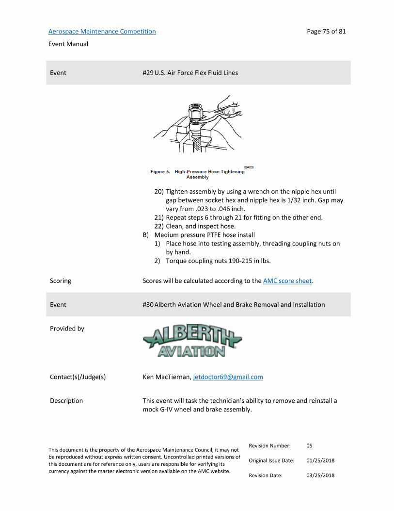
Aerospace Maintenance Competition
Event Manual
Page 75 of 81
This document is the property of the Aerospace Maintenance Council, it may not be reproduced without express written consent. Uncontrolled printed versions of this document are for reference only, users are responsible for verifying its currency against the master electronic version available on the AMC website.
Revision Number: 05
Original Issue Date: 01/25/2018
Revision Date: 03/25/2018
Event #29 U.S. Air Force Flex Fluid Lines
20) Tighten assembly by using a wrench on the nipple hex until
gap between socket hex and nipple hex is 1/32 inch. Gap may vary from .023 to .046 inch.
21) Repeat steps 6 through 21 for fitting on the other end. 22) Clean, and inspect hose.
Medium pressure PTFE hose install 1) Place hose into testing assembly, threading coupling nuts on
by hand. 2) Torque coupling nuts 190-215 in lbs.
Scoring Scores will be calculated according to the AMC score sheet.
Event #30 Alberth Aviation Wheel and Brake Removal and Installation
Provided by
Contact(s)/Judge(s) Ken MacTiernan, [email protected]
Description This event will task the technician’s ability to remove and reinstall a mock G-IV wheel and brake assembly.

Aerospace Maintenance Competition
Event Manual
Page 76 of 81
This document is the property of the Aerospace Maintenance Council, it may not be reproduced without express written consent. Uncontrolled printed versions of this document are for reference only, users are responsible for verifying its currency against the master electronic version available on the AMC website.
Revision Number: 05
Original Issue Date: 01/25/2018
Revision Date: 03/25/2018
Event #30 Alberth Aviation Wheel and Brake Removal and Installation
References G-IV Maintenance Manual, Chapter 32, Main Wheel Removal/Installation, Sections: 32-10-10, 32-20-10, 32-30-10 and 32-40-10
Maintenance Manual Placard
FAA Form 8130-3
Tools and equipment list None
Team members required Three
Instructions Main Wheel Removal 1) Ensure that Maintenance Manual Placard is on display in
cockpit before removing main wheel assembly. 2) Ensure brakes are set and Parking Brake Handle is set. 3) Ensure that nose wheels are chocked. 4) Ensure that landing gear opposite of the main gear which main
wheel assembly is to be removed from is chocked. NOTE: ONLY ONE MAIN GEAR MAY BE JACKED AT ONE TIME.
5) Install Down-Lock Pins in both main gear assemblies. Jack main gear which main wheel assembly is to be removed from. Ensure there is sufficient clearance between main wheel assembly and ramp for removal of main wheel assembly being removed. NOTE: TAKE PROPER PRECAUTIONS THAT EQUIPMENT IS CLEAR OF AIRCRAFTWHILE JACKING. DAMAGE TO EQUIPMENT MAY OCCUR IF PRECAUTIONS ARENOT TAKEN.
6) Remove hub cap bolts and hub cap. Loosen main wheel main nut to finger tight. Do not remove main nut.
7) Place tire/brake dolly under main wheel assembly and raise dolly to sufficiently hold main wheel assembly. Remove main wheel nut. Slowly pull dolly away from main gear till main wheel is completely off axle.
8) Inspect axle and visible main gear assembly for any obvious damage or defects.
9) Remove main wheel assembly from dolly and fill out appropriate 8130 Tag if main wheel is to be replaced.
Main Wheel Installation

Aerospace Maintenance Competition
Event Manual
Page 77 of 81
This document is the property of the Aerospace Maintenance Council, it may not be reproduced without express written consent. Uncontrolled printed versions of this document are for reference only, users are responsible for verifying its currency against the master electronic version available on the AMC website.
Revision Number: 05
Original Issue Date: 01/25/2018
Revision Date: 03/25/2018
Event #30 Alberth Aviation Wheel and Brake Removal and Installation
1) Place main wheel assembly securely on main wheel/brake dolly and position in front of axle.
2) Slowly position main wheel assembly onto axle. Install main wheel nut finger tight.
3) Release brakes and ensure Parking Brake Handle is not set. 4) While rotating main wheel assembly tighten main wheel nut
to a torque value of 200 In./Lbs. (+/- 10 In./Lbs.). 5) Loosen main wheel nut finger tight. Then while slowly rotating
main wheel assembly re-torque main wheel nut to a final torque of 130 In./Lbs. (+/- 10In./Lbs.). Remove main wheel/brake dolly away from aircraft. Install hub cap and torque hub cap bolts to 10 In./Lbs (+/- 0) and safety hub cap bolts.
6) Set brakes and ensure Parking Brake Handle is set. 7) Lower main gear jack. Remove and stow Down- Lock Pins from
both main gear assemblies. Chock main gear. NOTE: TAKE PROPER PRECAUTIONS THAT EQUIPMENT IS CLEAR OF AIRCRAFTWHILE LOWERING AIRCRAFT. DAMAGE TO EQUIPMENT MAY OCCUR IFPRECAUTIONS ARE NOT TAKEN.
8) Remove and stow Maintenance Manual Placard. Return aircraft to normal configuration.
Brake Assembly Removal 1) Remove main wheel assembly from brake position to be
removed. Reference G-IV Maintenance Manual Chapter 32 Section 32-10-10.
2) Release brakes and ensure Parking Brake Handle is not set. 3) Disconnect hydraulic lines from brake assembly. 4) Place main wheel/brake dolly underneath brake assembly and
jack till dolly firmly supports brake assembly. Remove brake support bolts.
5) Slowly pull brake assembly away from main gear till brake assembly is completely off axle.
6) Inspect axle and visible main gear assembly for any obvious damage or defects.
7) Remove brake assembly from dolly and fill out appropriate 8130 Tag if brake assembly is to be replaced.
Brake Assembly Installation 1) Place brake assembly onto main wheel/brake dolly and jack till
brake assembly is at sufficient height to slide onto axle.
Aerospace Maintenance Competition
Event Manual
Page 78 of 81
This document is the property of the Aerospace Maintenance Council, it may not be reproduced without express written consent. Uncontrolled printed versions of this document are for reference only, users are responsible for verifying its currency against the master electronic version available on the AMC website.
Revision Number: 05
Original Issue Date: 01/25/2018
Revision Date: 03/25/2018
Event #30 Alberth Aviation Wheel and Brake Removal and Installation
2) Slowly slide brake assembly till seated properly on axle. Install brake support bolts and torque to 30 In./Lbs. (+/- 5 In./Lbs.) Lower main wheel/brake dolly till clear of brake assembly and remove dolly from aircraft.
3) Connect hydraulic lines and safety. 4) Operate hydraulics and leak check brake assembly. Ensure
there are no leaks. 5) Install Main Wheel Assembly reference Maintenance Manual
Section: 32—20-10. Complete an 8130 tag with the following information:
1) Part Removed: 2) Part Number Removed: 3) Part Number Installed: 4) Serial Number Removed: 5) Serial Number Installed: 6) Aircraft Tail Number Removed From: 7) Aircraft Tail Number Installed On: 8) Date Removed: 9) Removed By: 10) Installed By: 11) Station: 12) Reason for Removal:
Scoring Scores will be calculated according to the AMC score sheet.

Aerospace Maintenance Competition
Event Manual
Page 79 of 81
This document is the property of the Aerospace Maintenance Council, it may not be reproduced without express written consent. Uncontrolled printed versions of this document are for reference only, users are responsible for verifying its currency against the master electronic version available on the AMC website.
Revision Number: 05
Original Issue Date: 01/25/2018
Revision Date: 03/25/2018
Record of Revisions
REVISION NUMBER
REVISION DATE
PAGE(S) AFFECTED REVISION DESCRIPTION
00 01/15/2018 ALL Original Issue
01 01/30/2018 42 Added reference links to Embry-Riddle Precision Measurement event, updated the number of persons required to one (to match the grouping schedule)
01 01/30/2018 16 Added link to Pioneers Mechanics in Aviation e-book
01 01/30/2018 37 Updated description and instructions for Safe-T-Cable event
01 01/30/2018 24 Corrected American Airlines & Atheer AiR Augmented Reality Pedestal criteria to require two competitors
02 02/20/2018 65 Added reference manual to United Fuel Tank Entry Precautions event
02 02/20/2018 15 Added references to Advanced Torque Products Accurate Torqueing event, added tools and equipment list, linked step-by-step procedures
02 02/20/2018 44 Revised ERAU reference to FAA general handbook with revised 2018 publication, added user manual reference to tooling list, corrected typo in tooling list
02 02/20/2018 30 Judge replacement for Boeing Fiber Optics event
02 02/20/2018 71 Added Airbus event
02 02/20/2018 59 Updated Air Force event criteria, added judge contact information
02 02/20/2018 56 Updates to PPG Sealant event criteria, including addition of referenced procedures
02 02/20/2018 All Revised standard score sheet according to competitor and judge feedback. Revised penalties to emphasize safety-related infractions and provided differing levels of event-specific penalties. Updated links to standard score sheet throughout.
03 02/20/2018 9-10 Corrected numbering for events 2, 3 and 4 in event grouping.
04 03/09/2018 35 Revised PPG event description, from four-part to three-part event
04 03/09/2018 9, 26 Removed event criteria for Boroscope event and event grouping, event has been cancelled.
04 03/09/2018 53 Added reference identifier language

Aerospace Maintenance Competition
Event Manual
Page 80 of 81
This document is the property of the Aerospace Maintenance Council, it may not be reproduced without express written consent. Uncontrolled printed versions of this document are for reference only, users are responsible for verifying its currency against the master electronic version available on the AMC website.
Revision Number: 05
Original Issue Date: 01/25/2018
Revision Date: 03/25/2018
REVISION NUMBER
REVISION DATE
PAGE(S) AFFECTED REVISION DESCRIPTION
04 03/09/2018 38 Changed Embry Riddle event referenced links to comprehensive versions of the IPC and overhaul manual.
04 03/09/2018 4 Added Monday start to schedule
04 03/09/2018 8 Added revised event layout
04 03/09/2018 All Renumbered events to coincide with layout; events are no longer listed according to alphabetical order, instead according to where they fall in the layout, from north to south.
04 03/09/2018 14 Added language to event section to clarify that all teams will compete in all events.
04 03/09/2018 19 Added photos to Daniels Manufacturing Electrical Troubleshooting event
04 03/09/2018 23 Removed event criteria for NDT event and event grouping, event has been cancelled.
04 03/09/2018 11-14 Added team list
04 03/09/2018 15 Added competition schedule
05 03/25/2018 11-12 Modified Alaska Airlines team names from Team 1 and Team 2 to Team ANC and Team SEA
05 03/25/2018 12 Updated Flybe team name (Team #39)
05 03/25/2018 21 Revised Safe-T-Cable instructions
05 03/25/2018 19 Added wiring diagram and updated DMC electrical troubleshooting description, tooling list and instructions.
05 03/25/2018 11 Added United States Air Force - Ogden Air Logistics Complex team #15
05 03/25/2018 14 Added United States Marine Corp - MALS 39 team # 69
05 03/25/2018 9 & 46 Changed number of competitors for FedEx event to three, to make up for the previously-cancelled boroscope event in that same event group.
05 03/25/2018 9 & 57 Changed the number of competitors for W.L. Gore & Associates, Inc. Dry Sealant Panel Installation to three, to make up for the previously-cancelled NDT event in that same event group.
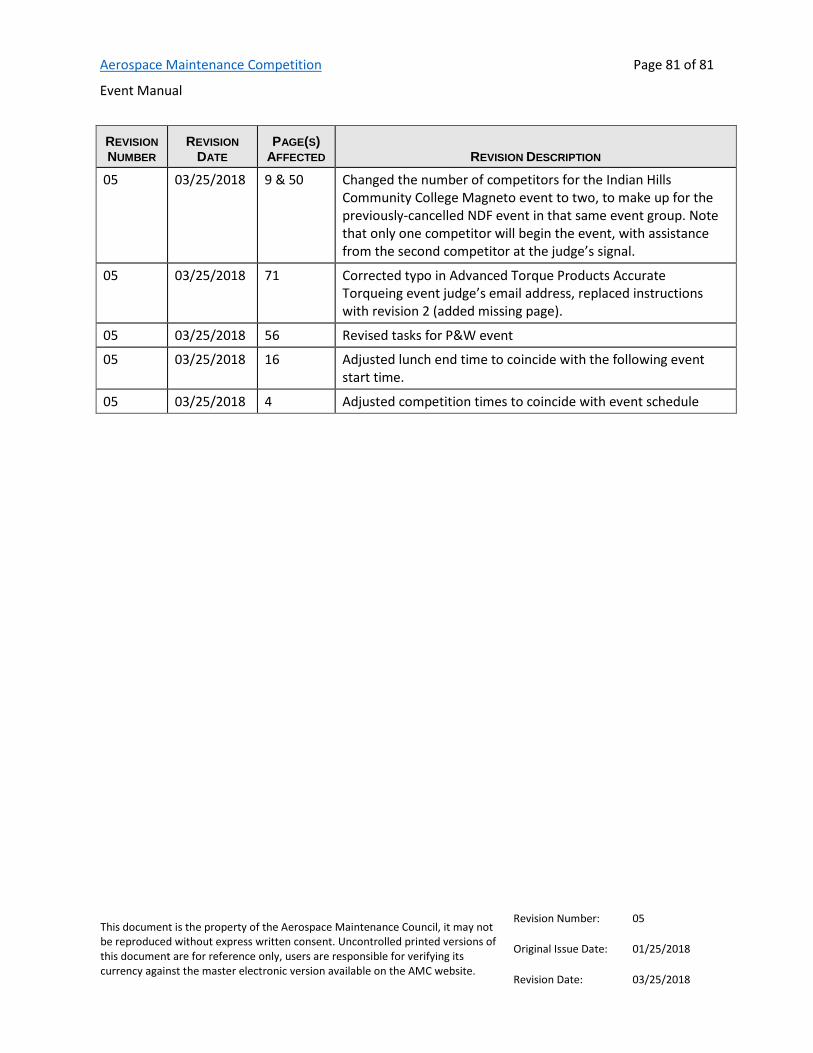
Aerospace Maintenance Competition
Event Manual
Page 81 of 81
This document is the property of the Aerospace Maintenance Council, it may not be reproduced without express written consent. Uncontrolled printed versions of this document are for reference only, users are responsible for verifying its currency against the master electronic version available on the AMC website.
Revision Number: 05
Original Issue Date: 01/25/2018
Revision Date: 03/25/2018
REVISION NUMBER
REVISION DATE
PAGE(S) AFFECTED REVISION DESCRIPTION
05 03/25/2018 9 & 50 Changed the number of competitors for the Indian Hills Community College Magneto event to two, to make up for the previously-cancelled NDF event in that same event group. Note that only one competitor will begin the event, with assistance from the second competitor at the judge’s signal.
05 03/25/2018 71 Corrected typo in Advanced Torque Products Accurate Torqueing event judge’s email address, replaced instructions with revision 2 (added missing page).
05 03/25/2018 56 Revised tasks for P&W event
05 03/25/2018 16 Adjusted lunch end time to coincide with the following event start time.
05 03/25/2018 4 Adjusted competition times to coincide with event schedule