AEROSPACE EQUIPMENT MAINTENANCE INSPECTION, … Orders/AFD... · aerospace equipment maintenance...
134
TO 00-20-1 TECHNICAL MANUAL AEROSPACE EQUIPMENT MAINTENANCE INSPECTION, DOCUMENTATION, POLICIES, AND PROCEDURES THIS MANUAL SUPERSEDES TO 00-20-1, DATED 11 JULY 2016. FOR QUESTIONS CONCERNING TECHNICAL CONTENT OF THIS TECHNICAL MANUAL, CONTACT THE APPLICABLE TECHNICAL CONTENT MANAGER (TCM) LISTED IN THE ENHANCED TECHNICAL INFORMATION MANAGEMENT SYSTEM (ETIMS). HQ AFMC/ A4FI, WPAFB, OH IS THE APPROVAL AND WAIVER AUTHORITY FOR THIS TECHNICAL MANUAL. DISTRIBUTION STATEMENT A - Approved for public release; distribution unlimited. HQ AFMC/PA Certificate Number AFMC PAX-04-329. Submit recommended changes or problems with this technical order to the applicable TO Manager (TOMA) listed in ETIMS using the Recom- mended Change Process in accordance with (IAW) TO 00-5-1. Published under authority of the Secretary of the Air Force 1 JUNE 2018
Transcript of AEROSPACE EQUIPMENT MAINTENANCE INSPECTION, … Orders/AFD... · aerospace equipment maintenance...

TO 00-20-1TECHNICAL MANUAL
AEROSPACE EQUIPMENT MAINTENANCE INSPECTION,DOCUMENTATION, POLICIES, AND PROCEDURES
THIS MANUAL SUPERSEDES TO 00-20-1, DATED 11 JULY 2016.
FOR QUESTIONS CONCERNING TECHNICAL CONTENT OF THIS TECHNICAL MANUAL, CONTACT THE APPLICABLE TECHNICALCONTENT MANAGER (TCM) LISTED IN THE ENHANCED TECHNICAL INFORMATION MANAGEMENT SYSTEM (ETIMS). HQ AFMC/
A4FI, WPAFB, OH IS THE APPROVAL AND WAIVER AUTHORITY FOR THIS TECHNICAL MANUAL.
DISTRIBUTION STATEMENT A - Approved for public release; distribution unlimited. HQ AFMC/PA Certificate Number AFMC PAX-04-329.Submit recommended changes or problems with this technical order to the applicable TO Manager (TOMA) listed in ETIMS using the Recom-mended Change Process in accordance with (IAW) TO 00-5-1.
Published under authority of the Secretary of the Air Force
1 JUNE 2018

Dates of issue for original and changed pages are:
Original. . . . . . . .0. . . . . . . .1 June 2018
TOTAL NUMBER OF PAGES IN THIS PUBLICATION IS 134, CONSISTING OF THE FOLLOWING:
Page *ChangeNo. No.
Page *ChangeNo. No.
Page *ChangeNo. No.
Title . . . . . . . . . . . . . . . . . . . . . . 0A . . . . . . . . . . . . . . . . . . . . . . . . 0i - vii . . . . . . . . . . . . . . . . . . . . .0viii Blank . . . . . . . . . . . . . . . . . . 01-1 - 1-2. . . . . . . . . . . . . . . . . . .02-1 - 2-11. . . . . . . . . . . . . . . . . .02-12 Blank. . . . . . . . . . . . . . . . . .03-1 - 3-6. . . . . . . . . . . . . . . . . . .04-1 - 4-6. . . . . . . . . . . . . . . . . . .05-1 - 5-45. . . . . . . . . . . . . . . . . .05-46 Blank. . . . . . . . . . . . . . . . . .06-1 - 6-5. . . . . . . . . . . . . . . . . . .06-6 Blank . . . . . . . . . . . . . . . . . . 07-1 - 7-12. . . . . . . . . . . . . . . . . .08-1 - 8-11. . . . . . . . . . . . . . . . . .08-12 Blank. . . . . . . . . . . . . . . . . .09-1 - 9-7. . . . . . . . . . . . . . . . . . .09-8 Blank . . . . . . . . . . . . . . . . . . 010-1 - 10-3 . . . . . . . . . . . . . . . . . 010-4 Blank. . . . . . . . . . . . . . . . . .0A-1 - A-2. . . . . . . . . . . . . . . . . .0B-1 - B-3 . . . . . . . . . . . . . . . . . . 0B-4 Blank . . . . . . . . . . . . . . . . . . 0Glossary 1 - Glossary 4 . . . . . . . . 0
TO 00-20-1
LIST OF EFFECTIVE PAGESINSERT LATEST CHANGED PAGES. DESTROY SUPERSEDED PAGES.
NOTE The portion of the text affected by the changes is indicated by a vertical line in the outer margins ofthe page. Changes to illustrations are indicated by shaded or screened areas, or by miniaturepointing hands.
* Zero in this column indicates an original page.
A USAF

TABLE OF CONTENTSChapter Page
LIST OF ILLUSTRATIONS . . . . . . . . . . . . . . . . . . . . . . . . . . . . . . . . . . . . . . . . . . . . . . . . . . . . . vi
LIST OF TABLES . . . . . . . . . . . . . . . . . . . . . . . . . . . . . . . . . . . . . . . . . . . . . . . . . . . . . . . . . . . . vi
FOREWORD . . . . . . . . . . . . . . . . . . . . . . . . . . . . . . . . . . . . . . . . . . . . . . . . . . . . . . . . . . . . . . . vii
1 GENERAL . . . . . . . . . . . . . . . . . . . . . . . . . . . . . . . . . . . . . . . . . . . . . . . . . . . . . . . . . . . . . . . . 1-1
1.1 Purpose . . . . . . . . . . . . . . . . . . . . . . . . . . . . . . . . . . . . . . . . . . . . . . . . . . . . . . . . . . . 1-11.1.1 Technical Order 00-20-Series Processes . . . . . . . . . . . . . . . . . . . . . . . . . . . . . . . . . . . . . . 1-11.2 Contractor Maintenance. . . . . . . . . . . . . . . . . . . . . . . . . . . . . . . . . . . . . . . . . . . . . . . . . 1-11.2.1 Operations Instructions . . . . . . . . . . . . . . . . . . . . . . . . . . . . . . . . . . . . . . . . . . . . . . . . . 1-1
2 AEROSPACE VEHICLE INSPECTIONS. . . . . . . . . . . . . . . . . . . . . . . . . . . . . . . . . . . . . . . . . . . . 2-1
2.1 General. . . . . . . . . . . . . . . . . . . . . . . . . . . . . . . . . . . . . . . . . . . . . . . . . . . . . . . . . . . . 2-12.1.1 Inspection Intervals. . . . . . . . . . . . . . . . . . . . . . . . . . . . . . . . . . . . . . . . . . . . . . . . . . . . 2-12.2 Inspection Requirements . . . . . . . . . . . . . . . . . . . . . . . . . . . . . . . . . . . . . . . . . . . . . . . . 2-12.2.1 Recurring Maintenance . . . . . . . . . . . . . . . . . . . . . . . . . . . . . . . . . . . . . . . . . . . . . . . . . 2-12.2.2 Inspection Concepts . . . . . . . . . . . . . . . . . . . . . . . . . . . . . . . . . . . . . . . . . . . . . . . . . . . 2-12.2.3 Inspection Cycle . . . . . . . . . . . . . . . . . . . . . . . . . . . . . . . . . . . . . . . . . . . . . . . . . . . . . 2-22.3 Specified Flying Period . . . . . . . . . . . . . . . . . . . . . . . . . . . . . . . . . . . . . . . . . . . . . . . . . 2-32.4 Inspection Types . . . . . . . . . . . . . . . . . . . . . . . . . . . . . . . . . . . . . . . . . . . . . . . . . . . . . 2-32.4.1 Pre-Flight Inspections . . . . . . . . . . . . . . . . . . . . . . . . . . . . . . . . . . . . . . . . . . . . . . . . . . 2-32.4.1.5 Pre-Launch Inspection or Walk-Around Inspection . . . . . . . . . . . . . . . . . . . . . . . . . . . . . . 2-32.4.2 End-of-Runway Inspection. . . . . . . . . . . . . . . . . . . . . . . . . . . . . . . . . . . . . . . . . . . . . . . 2-32.4.3 Thru-Flight Inspection. . . . . . . . . . . . . . . . . . . . . . . . . . . . . . . . . . . . . . . . . . . . . . . . . . 2-32.4.4 Quick Turn Inspection. . . . . . . . . . . . . . . . . . . . . . . . . . . . . . . . . . . . . . . . . . . . . . . . . . 2-42.4.5 Basic Post-Flight Inspection. . . . . . . . . . . . . . . . . . . . . . . . . . . . . . . . . . . . . . . . . . . . . . 2-42.4.6 Combined Pre-Flight/Basic Post-Flight Inspection . . . . . . . . . . . . . . . . . . . . . . . . . . . . . . . 2-42.4.7 Hourly Post-Flight Inspection. . . . . . . . . . . . . . . . . . . . . . . . . . . . . . . . . . . . . . . . . . . . . 2-42.4.8 Periodic Inspection . . . . . . . . . . . . . . . . . . . . . . . . . . . . . . . . . . . . . . . . . . . . . . . . . . . . 2-42.4.9 Phase Inspections . . . . . . . . . . . . . . . . . . . . . . . . . . . . . . . . . . . . . . . . . . . . . . . . . . . . . 2-42.4.10 Isochronal Inspection . . . . . . . . . . . . . . . . . . . . . . . . . . . . . . . . . . . . . . . . . . . . . . . . . . 2-42.4.11 Minor ISO Inspection . . . . . . . . . . . . . . . . . . . . . . . . . . . . . . . . . . . . . . . . . . . . . . . . . . 2-62.4.12 Major ISO Inspection . . . . . . . . . . . . . . . . . . . . . . . . . . . . . . . . . . . . . . . . . . . . . . . . . . 2-62.4.13 Home Station Check Inspection . . . . . . . . . . . . . . . . . . . . . . . . . . . . . . . . . . . . . . . . . . . 2-62.4.14 Programmed Depot Maintenance . . . . . . . . . . . . . . . . . . . . . . . . . . . . . . . . . . . . . . . . . . 2-62.4.15 Aerospace Vehicle Manufacturer Inspections. . . . . . . . . . . . . . . . . . . . . . . . . . . . . . . . . . . 2-62.4.16 No-Fly Calendar Inspections . . . . . . . . . . . . . . . . . . . . . . . . . . . . . . . . . . . . . . . . . . . . . 2-62.4.16.1 30-Day Inspection . . . . . . . . . . . . . . . . . . . . . . . . . . . . . . . . . . . . . . . . . . . . . . . . . . . . 2-62.4.16.2 90-Day Inspection . . . . . . . . . . . . . . . . . . . . . . . . . . . . . . . . . . . . . . . . . . . . . . . . . . . . 2-72.4.17 Transfer Inspections . . . . . . . . . . . . . . . . . . . . . . . . . . . . . . . . . . . . . . . . . . . . . . . . . . . 2-72.4.18 Acceptance Inspections . . . . . . . . . . . . . . . . . . . . . . . . . . . . . . . . . . . . . . . . . . . . . . . . . 2-72.4.19 One Time Inspections (OTIs) . . . . . . . . . . . . . . . . . . . . . . . . . . . . . . . . . . . . . . . . . . . . . 2-72.4.19.4 OTI Contents. . . . . . . . . . . . . . . . . . . . . . . . . . . . . . . . . . . . . . . . . . . . . . . . . . . . . . . . 2-82.4.20 In Process Inspection (IPI). . . . . . . . . . . . . . . . . . . . . . . . . . . . . . . . . . . . . . . . . . . . . . . 2-82.5 Aerospace Vehicles in Storage . . . . . . . . . . . . . . . . . . . . . . . . . . . . . . . . . . . . . . . . . . . . 2-92.6 Inspection Workcards . . . . . . . . . . . . . . . . . . . . . . . . . . . . . . . . . . . . . . . . . . . . . . . . . . 2-92.6.1 Requirements. . . . . . . . . . . . . . . . . . . . . . . . . . . . . . . . . . . . . . . . . . . . . . . . . . . . . . . . 2-92.6.2 AFTO Form 26 . . . . . . . . . . . . . . . . . . . . . . . . . . . . . . . . . . . . . . . . . . . . . . . . . . . . . . 2-92.7 Inspection Responsibilities . . . . . . . . . . . . . . . . . . . . . . . . . . . . . . . . . . . . . . . . . . . . . . . 2-92.7.1 Depot or Contractor Field Teams (DFT/CFT) . . . . . . . . . . . . . . . . . . . . . . . . . . . . . . . . . . 2-9
TO 00-20-1
i

Chapter Page
2.8 Service Life Extension Program (SLEP) . . . . . . . . . . . . . . . . . . . . . . . . . . . . . . . . . . . . . 2-92.8.1 SLEP Defined . . . . . . . . . . . . . . . . . . . . . . . . . . . . . . . . . . . . . . . . . . . . . . . . . . . . . . . 2-9
3 AEROSPACE EQUIPMENT FORMS DOCUMENTATION . . . . . . . . . . . . . . . . . . . . . . . . . . . . . . . 3-1
3.1 General. . . . . . . . . . . . . . . . . . . . . . . . . . . . . . . . . . . . . . . . . . . . . . . . . . . . . . . . . . . . 3-13.1.1 Aerospace Equipment Forms . . . . . . . . . . . . . . . . . . . . . . . . . . . . . . . . . . . . . . . . . . . . . 3-13.2 Maintenance Information Systems (MIS) . . . . . . . . . . . . . . . . . . . . . . . . . . . . . . . . . . . . . 3-13.3 Automated Forms. . . . . . . . . . . . . . . . . . . . . . . . . . . . . . . . . . . . . . . . . . . . . . . . . . . . . 3-23.4 Forms Entries . . . . . . . . . . . . . . . . . . . . . . . . . . . . . . . . . . . . . . . . . . . . . . . . . . . . . . . 3-23.5 Standard Date Format . . . . . . . . . . . . . . . . . . . . . . . . . . . . . . . . . . . . . . . . . . . . . . . . . . 3-23.6 Minimum Signature . . . . . . . . . . . . . . . . . . . . . . . . . . . . . . . . . . . . . . . . . . . . . . . . . . . 3-23.6.1 Maintenance . . . . . . . . . . . . . . . . . . . . . . . . . . . . . . . . . . . . . . . . . . . . . . . . . . . . . . . . 3-23.6.2 Aircrew . . . . . . . . . . . . . . . . . . . . . . . . . . . . . . . . . . . . . . . . . . . . . . . . . . . . . . . . . . . 3-23.6.3 Contractors . . . . . . . . . . . . . . . . . . . . . . . . . . . . . . . . . . . . . . . . . . . . . . . . . . . . . . . . . 3-23.7 Informational Notes . . . . . . . . . . . . . . . . . . . . . . . . . . . . . . . . . . . . . . . . . . . . . . . . . . . 3-23.8 Transfer of Documents . . . . . . . . . . . . . . . . . . . . . . . . . . . . . . . . . . . . . . . . . . . . . . . . . 3-33.8.1 Losing Organization . . . . . . . . . . . . . . . . . . . . . . . . . . . . . . . . . . . . . . . . . . . . . . . . . . . 3-33.8.2 Gaining Organization . . . . . . . . . . . . . . . . . . . . . . . . . . . . . . . . . . . . . . . . . . . . . . . . . . 3-33.9 Filing . . . . . . . . . . . . . . . . . . . . . . . . . . . . . . . . . . . . . . . . . . . . . . . . . . . . . . . . . . . . . 3-33.9.1 Historical File . . . . . . . . . . . . . . . . . . . . . . . . . . . . . . . . . . . . . . . . . . . . . . . . . . . . . . . 3-33.10 Disposition . . . . . . . . . . . . . . . . . . . . . . . . . . . . . . . . . . . . . . . . . . . . . . . . . . . . . . . . . 3-33.10.1 Forms and Documents . . . . . . . . . . . . . . . . . . . . . . . . . . . . . . . . . . . . . . . . . . . . . . . . . 3-33.11 Extended Storage Documentation . . . . . . . . . . . . . . . . . . . . . . . . . . . . . . . . . . . . . . . . . . 3-43.11.1 Maintaining Documents. . . . . . . . . . . . . . . . . . . . . . . . . . . . . . . . . . . . . . . . . . . . . . . . . 3-43.12 Air Card/Fuel Identiplate . . . . . . . . . . . . . . . . . . . . . . . . . . . . . . . . . . . . . . . . . . . . . . . . 3-43.13 Use of USAF Aerospace Vehicle by Bailment Contractors and Air Carrier Contract
Operators . . . . . . . . . . . . . . . . . . . . . . . . . . . . . . . . . . . . . . . . . . . . . . . . . . . . . . . . 3-43.13.1 Requirements. . . . . . . . . . . . . . . . . . . . . . . . . . . . . . . . . . . . . . . . . . . . . . . . . . . . . . . . 3-43.14 Processing of Documents During Depot Maintenance . . . . . . . . . . . . . . . . . . . . . . . . . . . . 3-43.14.1 Depot Maintenance Instructions . . . . . . . . . . . . . . . . . . . . . . . . . . . . . . . . . . . . . . . . . . . 3-43.15 Safeguarding/Documenting Classified Equipment . . . . . . . . . . . . . . . . . . . . . . . . . . . . . . . 3-6
4 SYMBOLS AND THEIR USE . . . . . . . . . . . . . . . . . . . . . . . . . . . . . . . . . . . . . . . . . . . . . . . . . . . 4-1
4.1 General. . . . . . . . . . . . . . . . . . . . . . . . . . . . . . . . . . . . . . . . . . . . . . . . . . . . . . . . . . . . 4-14.1.1 Symbols . . . . . . . . . . . . . . . . . . . . . . . . . . . . . . . . . . . . . . . . . . . . . . . . . . . . . . . . . . . 4-14.2 Red X . . . . . . . . . . . . . . . . . . . . . . . . . . . . . . . . . . . . . . . . . . . . . . . . . . . . . . . . . . . . 4-14.2.1 Usage. . . . . . . . . . . . . . . . . . . . . . . . . . . . . . . . . . . . . . . . . . . . . . . . . . . . . . . . . . . . . 4-14.3 Red Dash . . . . . . . . . . . . . . . . . . . . . . . . . . . . . . . . . . . . . . . . . . . . . . . . . . . . . . . . . . 4-24.3.1 Usage. . . . . . . . . . . . . . . . . . . . . . . . . . . . . . . . . . . . . . . . . . . . . . . . . . . . . . . . . . . . . 4-24.4 Red Diagonal . . . . . . . . . . . . . . . . . . . . . . . . . . . . . . . . . . . . . . . . . . . . . . . . . . . . . . . 4-34.4.1 Usage. . . . . . . . . . . . . . . . . . . . . . . . . . . . . . . . . . . . . . . . . . . . . . . . . . . . . . . . . . . . . 4-34.5 Clearing Red Symbols . . . . . . . . . . . . . . . . . . . . . . . . . . . . . . . . . . . . . . . . . . . . . . . . . 4-34.5.1 Requirements. . . . . . . . . . . . . . . . . . . . . . . . . . . . . . . . . . . . . . . . . . . . . . . . . . . . . . . . 4-34.6 Changing Symbols After an Original Entry . . . . . . . . . . . . . . . . . . . . . . . . . . . . . . . . . . . 4-44.6.1 Requirements. . . . . . . . . . . . . . . . . . . . . . . . . . . . . . . . . . . . . . . . . . . . . . . . . . . . . . . . 4-44.7 Downgrading a Red X for One-Time Flight . . . . . . . . . . . . . . . . . . . . . . . . . . . . . . . . . . . 4-54.7.1 Requirements. . . . . . . . . . . . . . . . . . . . . . . . . . . . . . . . . . . . . . . . . . . . . . . . . . . . . . . . 4-54.8 Red W (ICBM ONLY) . . . . . . . . . . . . . . . . . . . . . . . . . . . . . . . . . . . . . . . . . . . . . . . . . 4-54.8.1 Requirements. . . . . . . . . . . . . . . . . . . . . . . . . . . . . . . . . . . . . . . . . . . . . . . . . . . . . . . . 4-54.9 RED C . . . . . . . . . . . . . . . . . . . . . . . . . . . . . . . . . . . . . . . . . . . . . . . . . . . . . . . . . . . . 4-64.9.1 Requirements. . . . . . . . . . . . . . . . . . . . . . . . . . . . . . . . . . . . . . . . . . . . . . . . . . . . . . . . 4-6
5 AFTO FORM 781 SERIES . . . . . . . . . . . . . . . . . . . . . . . . . . . . . . . . . . . . . . . . . . . . . . . . . . . . . 5-1
TO 00-20-1
TABLE OF CONTENTS - CONTINUED
ii

Chapter Page
5.1 General Purpose of AFTO Form 781. . . . . . . . . . . . . . . . . . . . . . . . . . . . . . . . . . . . . . . . 5-15.2 Training Device Forms . . . . . . . . . . . . . . . . . . . . . . . . . . . . . . . . . . . . . . . . . . . . . . . . . 5-15.2.1 Mandatory AFTO Forms . . . . . . . . . . . . . . . . . . . . . . . . . . . . . . . . . . . . . . . . . . . . . . . . 5-15.3 Aerospace Vehicle Forms . . . . . . . . . . . . . . . . . . . . . . . . . . . . . . . . . . . . . . . . . . . . . . . 5-15.3.1 Mandatory AFTO Forms . . . . . . . . . . . . . . . . . . . . . . . . . . . . . . . . . . . . . . . . . . . . . . . . 5-15.3.2 Forms Binder . . . . . . . . . . . . . . . . . . . . . . . . . . . . . . . . . . . . . . . . . . . . . . . . . . . . . . . 5-15.4 Documenting Operational Checks and Functional Check Flights (FCF). . . . . . . . . . . . . . . . . 5-15.4.1 Requirements. . . . . . . . . . . . . . . . . . . . . . . . . . . . . . . . . . . . . . . . . . . . . . . . . . . . . . . . 5-15.4.1.1 Operational Checks. . . . . . . . . . . . . . . . . . . . . . . . . . . . . . . . . . . . . . . . . . . . . . . . . . . . 5-15.4.1.2 FCF . . . . . . . . . . . . . . . . . . . . . . . . . . . . . . . . . . . . . . . . . . . . . . . . . . . . . . . . . . . . . . 5-25.5 Recording Engine Storage . . . . . . . . . . . . . . . . . . . . . . . . . . . . . . . . . . . . . . . . . . . . . . . 5-25.6 AFTO Form 781, ARMS Aircrew/Mission Flight Data Document . . . . . . . . . . . . . . . . . . . . 5-25.6.1 AFTO Form 781 Documentation Instructions . . . . . . . . . . . . . . . . . . . . . . . . . . . . . . . . . . 5-35.7 AFTO Form 781A, Maintenance Discrepancy and Work Document . . . . . . . . . . . . . . . . . . . 5-65.7.1 AFTO Form 781A Documentation Instructions . . . . . . . . . . . . . . . . . . . . . . . . . . . . . . . . . 5-65.8 AFTO Form 781B, Communications Security (COMSEC) Equipment Record . . . . . . . . . . . . 5-145.8.1 AFTO Form 781B Documentation Instructions . . . . . . . . . . . . . . . . . . . . . . . . . . . . . . . . . 5-145.9 AFTO Form 781C, Avionics Configuration and Load Status Document. . . . . . . . . . . . . . . . . 5-165.9.1 AFTO Form 781C Documentation Instructions . . . . . . . . . . . . . . . . . . . . . . . . . . . . . . . . . 5-165.10 AFTO Form 781E, Accessory Replacement Document . . . . . . . . . . . . . . . . . . . . . . . . . . . . 5-195.10.1 AFTO Form 781E Documentation Instructions . . . . . . . . . . . . . . . . . . . . . . . . . . . . . . . . . 5-195.11 AFTO Form 781F, Aerospace Vehicle Identification Document . . . . . . . . . . . . . . . . . . . . . . 5-235.11.1 AFTO Form 781F Documentation Instructions . . . . . . . . . . . . . . . . . . . . . . . . . . . . . . . . . 5-235.12 AFTO Form 781G, General Mission Classification-Mission Symbols . . . . . . . . . . . . . . . . . . 5-235.13 AFTO Form 781H, Aerospace Vehicle Flight Status and Maintenance Document . . . . . . . . . . 5-275.13.1 AFTO Form 781H Documentation Instructions . . . . . . . . . . . . . . . . . . . . . . . . . . . . . . . . . 5-275.13.1.2 AFTO Form 781H Entries . . . . . . . . . . . . . . . . . . . . . . . . . . . . . . . . . . . . . . . . . . . . . . . 5-275.14 AFTO Form 781J, Aerospace Vehicle Engine Flight Document . . . . . . . . . . . . . . . . . . . . . . 5-335.14.1 AFTO Form 781J Documentation Instructions . . . . . . . . . . . . . . . . . . . . . . . . . . . . . . . . . 5-335.15 AFTO Form 781K, Aerospace Vehicle Inspection, Engine Data, Calendar Inspection, and De-
layed Discrepancy Document . . . . . . . . . . . . . . . . . . . . . . . . . . . . . . . . . . . . . . . . . . . 5-375.15.1 AFTO Form 781K Documentation Instructions . . . . . . . . . . . . . . . . . . . . . . . . . . . . . . . . . 5-375.16 AFTO Form 781M, Status Symbols and Functional System Codes . . . . . . . . . . . . . . . . . . . 5-415.17 AFTO Form 781P, Support General Documentation Record . . . . . . . . . . . . . . . . . . . . . . . . 5-415.17.1 AFTO Form 781P Process . . . . . . . . . . . . . . . . . . . . . . . . . . . . . . . . . . . . . . . . . . . . . . . 5-415.18 Paperless Process . . . . . . . . . . . . . . . . . . . . . . . . . . . . . . . . . . . . . . . . . . . . . . . . . . . . . 5-415.18.1 Utilizing Paperless Process . . . . . . . . . . . . . . . . . . . . . . . . . . . . . . . . . . . . . . . . . . . . . . 5-41
6 ACCESSORY REPLACEMENT AND REUSE PROCEDURES . . . . . . . . . . . . . . . . . . . . . . . . . . . . 6-1
6.1 General. . . . . . . . . . . . . . . . . . . . . . . . . . . . . . . . . . . . . . . . . . . . . . . . . . . . . . . . . . . . 6-16.1.1 Accessory Replacement and Reuse . . . . . . . . . . . . . . . . . . . . . . . . . . . . . . . . . . . . . . . . . 6-16.2 TCI Replacement . . . . . . . . . . . . . . . . . . . . . . . . . . . . . . . . . . . . . . . . . . . . . . . . . . . . . 6-16.2.1 Replacement Policies . . . . . . . . . . . . . . . . . . . . . . . . . . . . . . . . . . . . . . . . . . . . . . . . . . 6-16.2.1.6 TCI Operating Time . . . . . . . . . . . . . . . . . . . . . . . . . . . . . . . . . . . . . . . . . . . . . . . . . . . 6-26.3 TCI Reuse. . . . . . . . . . . . . . . . . . . . . . . . . . . . . . . . . . . . . . . . . . . . . . . . . . . . . . . . . . 6-36.3.1 Reuse Policies . . . . . . . . . . . . . . . . . . . . . . . . . . . . . . . . . . . . . . . . . . . . . . . . . . . . . . . 6-3
7 SUPPORT EQUIPMENT (SE) . . . . . . . . . . . . . . . . . . . . . . . . . . . . . . . . . . . . . . . . . . . . . . . . . . . 7-1
7.1 Purpose . . . . . . . . . . . . . . . . . . . . . . . . . . . . . . . . . . . . . . . . . . . . . . . . . . . . . . . . . . . 7-17.1.1 General SE Forms Usage. . . . . . . . . . . . . . . . . . . . . . . . . . . . . . . . . . . . . . . . . . . . . . . . 7-17.1.1.4 TMDE . . . . . . . . . . . . . . . . . . . . . . . . . . . . . . . . . . . . . . . . . . . . . . . . . . . . . . . . . . . . 7-17.1.1.5 Training Equipment . . . . . . . . . . . . . . . . . . . . . . . . . . . . . . . . . . . . . . . . . . . . . . . . . . . 7-27.1.1.6 Machinery/Shop Equipment . . . . . . . . . . . . . . . . . . . . . . . . . . . . . . . . . . . . . . . . . . . . . . 7-2
TO 00-20-1
TABLE OF CONTENTS - CONTINUED
iii
Chapter Page
7.2 AFTO Form 244/245 . . . . . . . . . . . . . . . . . . . . . . . . . . . . . . . . . . . . . . . . . . . . . . . . . . 7-27.2.1 Requirements. . . . . . . . . . . . . . . . . . . . . . . . . . . . . . . . . . . . . . . . . . . . . . . . . . . . . . . . 7-27.2.2 Location . . . . . . . . . . . . . . . . . . . . . . . . . . . . . . . . . . . . . . . . . . . . . . . . . . . . . . . . . . . 7-27.3 Inspection Requirements . . . . . . . . . . . . . . . . . . . . . . . . . . . . . . . . . . . . . . . . . . . . . . . . 7-37.3.1 Servicing Inspection . . . . . . . . . . . . . . . . . . . . . . . . . . . . . . . . . . . . . . . . . . . . . . . . . . . 7-37.3.2 Operator Inspection . . . . . . . . . . . . . . . . . . . . . . . . . . . . . . . . . . . . . . . . . . . . . . . . . . . 7-37.3.3 Special Inspections . . . . . . . . . . . . . . . . . . . . . . . . . . . . . . . . . . . . . . . . . . . . . . . . . . . . 7-37.3.4 Scheduled Inspections and Lubrications . . . . . . . . . . . . . . . . . . . . . . . . . . . . . . . . . . . . . . 7-37.3.5 In Process Inspection (IPI). . . . . . . . . . . . . . . . . . . . . . . . . . . . . . . . . . . . . . . . . . . . . . . 7-47.3.6 Preventative Maintenance (PM) . . . . . . . . . . . . . . . . . . . . . . . . . . . . . . . . . . . . . . . . . . . 7-47.4 War Reserve Material (WRM) or Mobility Equipment . . . . . . . . . . . . . . . . . . . . . . . . . . . . 7-47.5 SE Document Administration . . . . . . . . . . . . . . . . . . . . . . . . . . . . . . . . . . . . . . . . . . . . . 7-57.5.1 General Requirements . . . . . . . . . . . . . . . . . . . . . . . . . . . . . . . . . . . . . . . . . . . . . . . . . . 7-57.6 AFTO Form 244/245 Documentation . . . . . . . . . . . . . . . . . . . . . . . . . . . . . . . . . . . . . . . 7-57.6.1 AFTO Form 244, Part I. . . . . . . . . . . . . . . . . . . . . . . . . . . . . . . . . . . . . . . . . . . . . . . . . 7-57.6.2 AFTO Form 244, Part II . . . . . . . . . . . . . . . . . . . . . . . . . . . . . . . . . . . . . . . . . . . . . . . . 7-57.6.3 AFTO Form 244, Part III . . . . . . . . . . . . . . . . . . . . . . . . . . . . . . . . . . . . . . . . . . . . . . . 7-67.6.4 AFTO Form 244, Part IV . . . . . . . . . . . . . . . . . . . . . . . . . . . . . . . . . . . . . . . . . . . . . . . 7-67.6.5 AFTO Form 244/245, Part V . . . . . . . . . . . . . . . . . . . . . . . . . . . . . . . . . . . . . . . . . . . . . 7-67.6.6 AFTO Form 245 . . . . . . . . . . . . . . . . . . . . . . . . . . . . . . . . . . . . . . . . . . . . . . . . . . . . . 7-77.6.7 Disposition Instructions . . . . . . . . . . . . . . . . . . . . . . . . . . . . . . . . . . . . . . . . . . . . . . . . . 7-77.6.8 Closing Out AFTO Form 244/245. . . . . . . . . . . . . . . . . . . . . . . . . . . . . . . . . . . . . . . . . . 7-7
8 TRANSFER, STORAGE, AND DEPOT MAINTENANCE. . . . . . . . . . . . . . . . . . . . . . . . . . . . . . . . 8-1
8.1 Transferring Aerospace Vehicles . . . . . . . . . . . . . . . . . . . . . . . . . . . . . . . . . . . . . . . . . . . 8-18.1.1 Requirements. . . . . . . . . . . . . . . . . . . . . . . . . . . . . . . . . . . . . . . . . . . . . . . . . . . . . . . . 8-18.1.2 AFTO Form 290, Aerospace Vehicle Delivery Receipt . . . . . . . . . . . . . . . . . . . . . . . . . . . . 8-68.1.3 AMARG Desert Operations and Maintenance Storage Activities . . . . . . . . . . . . . . . . . . . . . 8-98.1.4 Preparation of Aerospace Vehicles for Delivery to a Depot/Contractor Facility. . . . . . . . . . . . 8-98.1.5 Preparation of Aerospace Vehicle for Transfer by One-Time Flight . . . . . . . . . . . . . . . . . . . 8-108.1.6 Preparation of Aerospace Vehicle to be Transferred for Inactive Long-Term Storage . . . . . . . . 8-108.1.7 Preparation of Aerospace Vehicle to be Transferred Sold or Disposed. . . . . . . . . . . . . . . . . . 8-11
9 MAINTENANCE HISTORICAL DOCUMENTATION. . . . . . . . . . . . . . . . . . . . . . . . . . . . . . . . . . . 9-1
9.1 General. . . . . . . . . . . . . . . . . . . . . . . . . . . . . . . . . . . . . . . . . . . . . . . . . . . . . . . . . . . . 9-19.1.1 Historical Documentation Requirements. . . . . . . . . . . . . . . . . . . . . . . . . . . . . . . . . . . . . . 9-19.1.1.4 Historical Engine Documentation . . . . . . . . . . . . . . . . . . . . . . . . . . . . . . . . . . . . . . . . . . 9-19.1.1.5 In-Flight Engine Shutdowns. . . . . . . . . . . . . . . . . . . . . . . . . . . . . . . . . . . . . . . . . . . . . . 9-29.1.1.6 Engine Transfers . . . . . . . . . . . . . . . . . . . . . . . . . . . . . . . . . . . . . . . . . . . . . . . . . . . . . 9-39.1.1.7 Pylon Historical Reporting. . . . . . . . . . . . . . . . . . . . . . . . . . . . . . . . . . . . . . . . . . . . . . . 9-39.1.1.8 Propeller Historical Reporting . . . . . . . . . . . . . . . . . . . . . . . . . . . . . . . . . . . . . . . . . . . . 9-39.1.1.9 Landing Gear and Strut Historical Reporting . . . . . . . . . . . . . . . . . . . . . . . . . . . . . . . . . . 9-39.1.1.10 Helicopter Components Historical Reporting . . . . . . . . . . . . . . . . . . . . . . . . . . . . . . . . . . 9-39.1.1.11 KC-135 Boom Historical Reporting . . . . . . . . . . . . . . . . . . . . . . . . . . . . . . . . . . . . . . . . 9-39.1.1.12 KC-135 MPRS Pod Historical Reporting . . . . . . . . . . . . . . . . . . . . . . . . . . . . . . . . . . . . . 9-39.1.1.13 Guns and Gun Barrels. . . . . . . . . . . . . . . . . . . . . . . . . . . . . . . . . . . . . . . . . . . . . . . . . . 9-39.1.1.14 Munitions Materiel Handling Equipment . . . . . . . . . . . . . . . . . . . . . . . . . . . . . . . . . . . . . 9-39.1.1.16 Temporary Fuel Leak Repair Historical Reporting . . . . . . . . . . . . . . . . . . . . . . . . . . . . . . . 9-49.2 Non-Automated Procedures . . . . . . . . . . . . . . . . . . . . . . . . . . . . . . . . . . . . . . . . . . . . . . 9-49.2.1 AFTO Forms . . . . . . . . . . . . . . . . . . . . . . . . . . . . . . . . . . . . . . . . . . . . . . . . . . . . . . . . 9-49.3 AFTO Form 95, Significant Historical Data Record . . . . . . . . . . . . . . . . . . . . . . . . . . . . . . 9-49.3.1 AFTO Form 95 Entries . . . . . . . . . . . . . . . . . . . . . . . . . . . . . . . . . . . . . . . . . . . . . . . . . 9-49.3.2 AFTO Form 95 Special Applications . . . . . . . . . . . . . . . . . . . . . . . . . . . . . . . . . . . . . . . . 9-5
TO 00-20-1
TABLE OF CONTENTS - CONTINUED
iv

Chapter Page
9.4 Maintenance and Disposition of Historical Records . . . . . . . . . . . . . . . . . . . . . . . . . . . . . . 9-59.4.1 Weapon System or Component Overhaul . . . . . . . . . . . . . . . . . . . . . . . . . . . . . . . . . . . . . 9-59.4.2 Incorrect Historical Records . . . . . . . . . . . . . . . . . . . . . . . . . . . . . . . . . . . . . . . . . . . . . . 9-59.4.3 Completed Historical Records . . . . . . . . . . . . . . . . . . . . . . . . . . . . . . . . . . . . . . . . . . . . 9-59.4.4 Annual Review . . . . . . . . . . . . . . . . . . . . . . . . . . . . . . . . . . . . . . . . . . . . . . . . . . . . . . 9-5
10 ICBM FACILITY AND SUPPORT EQUIPMENT INSPECTIONS. . . . . . . . . . . . . . . . . . . . . . . . . . . 10-1
10.1 General. . . . . . . . . . . . . . . . . . . . . . . . . . . . . . . . . . . . . . . . . . . . . . . . . . . . . . . . . . . . 10-110.1.1 Inspection Intervals. . . . . . . . . . . . . . . . . . . . . . . . . . . . . . . . . . . . . . . . . . . . . . . . . . . . 10-110.2 Inspection Requirements . . . . . . . . . . . . . . . . . . . . . . . . . . . . . . . . . . . . . . . . . . . . . . . . 10-110.2.1 Scheduled Inspections . . . . . . . . . . . . . . . . . . . . . . . . . . . . . . . . . . . . . . . . . . . . . . . . . . 10-110.2.2 Modified Inspection Workcards. . . . . . . . . . . . . . . . . . . . . . . . . . . . . . . . . . . . . . . . . . . . 10-110.3 Inspection Types . . . . . . . . . . . . . . . . . . . . . . . . . . . . . . . . . . . . . . . . . . . . . . . . . . . . . 10-110.3.1 Pre-Issue Inspection . . . . . . . . . . . . . . . . . . . . . . . . . . . . . . . . . . . . . . . . . . . . . . . . . . . 10-110.3.2 Isochronal (ISO) Inspections . . . . . . . . . . . . . . . . . . . . . . . . . . . . . . . . . . . . . . . . . . . . . 10-210.3.3 Periodic Inspection . . . . . . . . . . . . . . . . . . . . . . . . . . . . . . . . . . . . . . . . . . . . . . . . . . . . 10-210.3.4 Special Inspection . . . . . . . . . . . . . . . . . . . . . . . . . . . . . . . . . . . . . . . . . . . . . . . . . . . . 10-210.3.5 Trainer Daily Inspection . . . . . . . . . . . . . . . . . . . . . . . . . . . . . . . . . . . . . . . . . . . . . . . . 10-210.3.6 Acceptance Inspection. . . . . . . . . . . . . . . . . . . . . . . . . . . . . . . . . . . . . . . . . . . . . . . . . . 10-210.3.7 One Time Inspection (OTI) . . . . . . . . . . . . . . . . . . . . . . . . . . . . . . . . . . . . . . . . . . . . . . 10-210.4 Documentation. . . . . . . . . . . . . . . . . . . . . . . . . . . . . . . . . . . . . . . . . . . . . . . . . . . . . . . 10-210.4.1 Isochronal Inspections. . . . . . . . . . . . . . . . . . . . . . . . . . . . . . . . . . . . . . . . . . . . . . . . . . 10-210.5 Deviations. . . . . . . . . . . . . . . . . . . . . . . . . . . . . . . . . . . . . . . . . . . . . . . . . . . . . . . . . . 10-310.5.1 Deviation Approvals . . . . . . . . . . . . . . . . . . . . . . . . . . . . . . . . . . . . . . . . . . . . . . . . . . . 10-3
APPENDIX A APPLICABLE TECHNICAL ORDERS AND SUPPORTING DIRECTIVES . . . . . . . . . A-1
A.1 Applicable Technical Orders . . . . . . . . . . . . . . . . . . . . . . . . . . . . . . . . . . . . . . . . . . . . . A-1A.2 Supporting Directives . . . . . . . . . . . . . . . . . . . . . . . . . . . . . . . . . . . . . . . . . . . . . . . . . . A-1
APPENDIX B ACRONYMS . . . . . . . . . . . . . . . . . . . . . . . . . . . . . . . . . . . . . . . . . . . . . . . . . . . . B-1
B.1 List of Acronyms . . . . . . . . . . . . . . . . . . . . . . . . . . . . . . . . . . . . . . . . . . . . . . . . . . . . . B-1
GLOSSARY . . . . . . . . . . . . . . . . . . . . . . . . . . . . . . . . . . . . . . . . . . . . . . . . . . . . . . . . . . . . . . . . . Glossary 1
TO 00-20-1
TABLE OF CONTENTS - CONTINUED
v

LIST OF ILLUSTRATIONS
Number PageTitle
2-1 AFTO FORM 26, Aerospace Vehicle Inspection Work Document. . . . . . . . . . . . . . . . . . . . . . . . . 2-115-1 AFTO FORM 781, ARMS Aircrew/Mission Flight Data Document (Front) . . . . . . . . . . . . . . . . . . 5-45-2 AFTO FORM 781, ARMS Aircrew/Mission Flight Data Document (Reverse) . . . . . . . . . . . . . . . . 5-55-3 AFTO FORM 781A, Maintenance Discrepancy and Work Document . . . . . . . . . . . . . . . . . . . . . . 5-125-4 AFTO FORM 781A, Maintenance Discrepancy and Work Document (Reverse) . . . . . . . . . . . . . . . 5-135-5 AFTO FORM 781B, Communication Security (COMSEC) Equipment Record. . . . . . . . . . . . . . . . 5-155-6 AFTO FORM 781C, Avionics Configuration and Loads Status Document . . . . . . . . . . . . . . . . . . . 5-175-7 AFTO FORM 781C, Avionics Configuration and Load Status Document (Reverse). . . . . . . . . . . . . 5-185-8 AFTO FORM 781E, Accessory Replacement Document . . . . . . . . . . . . . . . . . . . . . . . . . . . . . . . 5-215-9 AFTO FORM 781E, Accessory Replacement Document . . . . . . . . . . . . . . . . . . . . . . . . . . . . . . . 5-225-10 AFTO FORM 781F, Aerospace Vehicle identification Document . . . . . . . . . . . . . . . . . . . . . . . . . 5-245-11 AFTO FORM 781G, General Mission Classifications-Mission Symbols . . . . . . . . . . . . . . . . . . . . 5-255-12 AFTO FORM 781G, General Mission Classifications-Mission (Reverse) . . . . . . . . . . . . . . . . . . . . 5-265-13 AFTO FORM 781H, Aerospace Vehicle Flight Status and Maintenance Document . . . . . . . . . . . . . 5-315-14 AFTO FORM 781H, Aerospace Vehicle Flight Status and Maintenance Document (Reverse) . . . . . . 5-325-15 AFTO FORM 781J, Aerospace Vehicle Engine Flight Document . . . . . . . . . . . . . . . . . . . . . . . . . 5-355-16 AFTO FORM 781J, Aerospace Vehicle Engine Flight Document (Reverse) . . . . . . . . . . . . . . . . . . 5-365-17 AFTO FORM 781K, Aerospace Vehicle Inspection, Engine Data, Calendar Inspection and Delayed
Discrepancy Document . . . . . . . . . . . . . . . . . . . . . . . . . . . . . . . . . . . . . . . . . . . . . . . . . . . 5-395-18 AFTO FORM 781K, Aerospace Vehicle Inspection, Engine Data, Calendar Inspection and Delayed
Discrepancy Document (Reverse) . . . . . . . . . . . . . . . . . . . . . . . . . . . . . . . . . . . . . . . . . . . . 5-405-19 AFTO FORM 781M, Status Symbols and Functional System Codes. . . . . . . . . . . . . . . . . . . . . . . 5-425-20 AFTO FORM 781M, Status Symbols and Functional System Codes (Reverse). . . . . . . . . . . . . . . . 5-435-21 AFTO Form 781P, Support General Documentation . . . . . . . . . . . . . . . . . . . . . . . . . . . . . . . . . . 5-445-22 AFTO Form 367, Aircraft Discrepancy Gig Sheet . . . . . . . . . . . . . . . . . . . . . . . . . . . . . . . . . . . 5-457-1 AFTO FORM 244, Industrial/Support Equipment Record (Front) . . . . . . . . . . . . . . . . . . . . . . . . . 7-97-2 AFTO FORM 244, Industrial/Support Equipment Record (Reverse) . . . . . . . . . . . . . . . . . . . . . . . 7-107-3 AFTO FORM 245, Industrial Support Equipment (Continuation) (Front). . . . . . . . . . . . . . . . . . . . 7-117-4 AFTO FORM 245, Industrial Support Equipment (Continuation) (Reverse) . . . . . . . . . . . . . . . . . . 7-128-1 AFTO FORM 345, Aerospace Vehicle Transfer Inspection Checklist and Certification (Front) . . . . . 8-48-2 AFTO FORM 345, Aerospace Vehicle Transfer Inspection Checklist and Certification (Reverse). . . . 8-58-3 AFTO FORM 290, Aerospace Vehicle Delivery Receipt . . . . . . . . . . . . . . . . . . . . . . . . . . . . . . . 8-89-1 AFTO FORM 95, Significant Historical Data (Front) . . . . . . . . . . . . . . . . . . . . . . . . . . . . . . . . . 9-69-2 AFTO FORM 95, Significant Historical Data (Back) . . . . . . . . . . . . . . . . . . . . . . . . . . . . . . . . . 9-710-1 IMDS Verify Equip Status . . . . . . . . . . . . . . . . . . . . . . . . . . . . . . . . . . . . . . . . . . . . . . . . . . . 10-3
LIST OF TABLES
Number PageTitle
2-1 Periodic Concept . . . . . . . . . . . . . . . . . . . . . . . . . . . . . . . . . . . . . . . . . . . . . . . . . . . . . . . . . 2-12-2 Phase Concept . . . . . . . . . . . . . . . . . . . . . . . . . . . . . . . . . . . . . . . . . . . . . . . . . . . . . . . . . . . 2-22-3 Isochronal Concept . . . . . . . . . . . . . . . . . . . . . . . . . . . . . . . . . . . . . . . . . . . . . . . . . . . . . . . . 2-22-4 Programmed Depot Maintenance (PDM) . . . . . . . . . . . . . . . . . . . . . . . . . . . . . . . . . . . . . . . . . 2-22-5 Aerospace Vehicle Manufacturer Inspection Concept . . . . . . . . . . . . . . . . . . . . . . . . . . . . . . . . . 2-26-1 Red Symbol Entries for Installed Aerospace Equipment Time Change Items . . . . . . . . . . . . . . . . . 6-46-2 Processing Time Change Items Where Previous Operating Time is Unknown or Known to be
Invalid . . . . . . . . . . . . . . . . . . . . . . . . . . . . . . . . . . . . . . . . . . . . . . . . . . . . . . . . . . . . . . 6-5
TO 00-20-1
vi

FOREWORD
1 PURPOSE.
This technical manual provides a description of the Aerospace Equipment Maintenance Inspection, Documentation, Policies,and Procedures. Instructions for safe and proper storage, handling, inspection, testing, maintenance, and preparation for useare also provided.
2 USE OF THIS MANUAL.
The table of contents indicates chapter, paragraph, title, and page numbers to facilitate location of information. Illustrations,tables, and diagrams, when applicable, are located throughout the publication to supplement the text material. A list ofillustrations and a list of tables indicate the number, title, and location. Abbreviations, phrases, and words which are on adecal, a placard or an engraving are set forth in the text exactly as they appear on the decal, the placard or the engraving.
3 DEFINITIONS.
The word SHALL is used to express a provision that is binding. The words SHOULD and MAY are used when it isnecessary to express nonmandatory provisions. WILL may be used to express a mandatory declaration of purpose or when itis necessary to express a future event.
4 ABBREVIATIONS AND ACRONYMS.
All abbreviations used in this manual are in accordance with abbreviations per ASME Y14.38M, Abbreviations and Acro-nyms for use on drawings and related documents: Use acronym list from Appendix B.
NOTE
Acronyms used only once in the TO are not included in this list.
5 LIST OF RELATED PUBLICATIONS.
These publications contain information in support of this technical manual. Use List of Related Publications from AppendixA.
6 IMPROVEMENT REPORTS.
All changes to this TO must be forwarded through users MAJCOM. Submit change requests using AFTO Form 22, IAW TO00-5-1.
TO 00-20-1
vii/(viii blank)


CHAPTER 1GENERAL
1.1 PURPOSE.
1.1.1 Technical Order 00-20-Series Processes. This Technical Order (TO) establishes the policies and procedures foruse of 00-20-series TOs and provides weapon system and equipment maintenance inspection and documentation guidance. Italso implements the policies of AFI 21-101, AFI 11-301V1, and AFI 21-102.
1.1.1.1 Unless otherwise specified, the term AEROSPACE EQUIPMENT in this technical order refers to weapon systemsand equipment such as aerospace vehicles, equipment, missiles (with the exception of Air-To-Air and Air-To-Ground mis-siles), nuclear weapons, Test Measurement and Diagnostic Equipment (TMDE), trainers, training equipment, engines, FlightSupport Equipment (FSE), industrial plant equipment, and all related Support Equipment (SE). This TO is applicable to allorganizations maintaining this equipment.
1.1.1.2 MAJCOMs may supplement 00-20-series TOs as required. Refer to TO 00-5-1 for MAJCOM, Base, and UnitSupplement requirements. For the purpose of 00-20-series TOs, the term AFMC Single Manager (SM) includes SystemProgram Directors (SPD), Product Group Managers (PGM), and Supply Chain Managers (SCM). For the purpose of main-tenance policy, the lead commands are Air Combat Command, Air Mobility Command, Air Force Special OperationsCommand, Air Education and Training Command, Air National Guard, Air Force Reserve Command, Air Force SpaceCommand, Global Strike Command and Air Force Materiel Command.
1.1.1.3 Air Force agencies will not furnish maintenance data in any form to contractors unless the applicable LeadCommand, Field Operating Agency or Weapon System Manager, as appropriate, has granted approval. Operating activitieswill not perform any additional documentation requirements above those outlined in this TO without MAJCOM/LeadCommand and HQ USAF/A4LM approval.
1.1.1.4 In 00-20-series TOs, the designation, GP/CC is used to represent the Maintenance Group Commander. At test sitesor activities which do not have a GP/CC, it will be the responsibility of the Chief of Maintenance, Chief of Test ForceTeams, Air Mobility Squadron Commander, Installation Team Chief or equivalent (as determined by the MAJCOM/A4) toensure that the criteria of this TO is complied with.
1.1.1.5 Forward requests for waivers to this TO through MAJCOM maintenance policy to HQ AFMC/A4FI.
1.2 CONTRACTOR MAINTENANCE.
1.2.1 Operations Instructions. The contractor will provide the Air Force contract administration office with a list ofpersonnel who are authorized to certify that Aerospace Equipment is safe for flight or use. This certification list should bekept to a minimum to meet mission requirements. Any changes to the list will be immediately forwarded to the contractadministration office. The listing will specifically identify the personnel who are authorized to:
a. Sign exceptional releases.
b. Downgrade Red X or Red W conditions.
c. Sign off Red X or Red W symbol.
d. Certify operational capability.
e. Perform functional check flights (if applicable).
f. Update weight and balance records IAW TO 1-1B-50.
TO 00-20-1
1-1

1.2.1.1 The contractor will develop and maintain a program to ensure that personnel are trained in the areas specified inthe contract. The program will have provisions for contractor certification/recertification of personnel authorized to performthe specific functions or to operate various support equipment IAW AFI 21-101 and other applicable directives.
1.2.1.2 The contract administration office will ensure that the contractor performs the maintenance management anddocumentation requirements prescribed in applicable TOs. In addition, the contract administration office will ensure that theapplicable TOs are referenced as provisions in the contract.
TO 00-20-1
1-2

CHAPTER 2AEROSPACE VEHICLE INSPECTIONS
2.1 GENERAL.
2.1.1 Inspection Intervals. Intervals required for Air Force aerospace vehicle inspections are prescribed in applicableMission Design Series (MDS) specific -6 TO maintenance manuals, item technical orders, inspection workcards, checklists,commercial manuals or depot engineering data. All requirements pertaining to inspections will normally be accomplishedconcurrently to avoid complications in scheduling and controlling the required maintenance. The inspection concepts foraerospace vehicles are periodic, phase, isochronal, Programmed Depot Maintenance (PDM), and aerospace vehicle manu-facturer maintenance. The GP/CC establishes necessary controls to ensure that the periodic, phase, or isochronal inspectionsare accomplished at or near the scheduled due time as authorized in applicable TOs or approved waivers. GP/CC mayincrease the frequency or scope of scheduled inspections or individual inspection requirements, when required for temporarysituations. Scheduling deviations of periodic, phase, or isochronal inspections beyond what is authorized in aerospacevehicle specific technical manuals, must be approved through the SM in coordination with the owning MAJCOM. Schedul-ing deviations that effect PDM or aerospace vehicle manufacturer maintenance, must be approved through the SingleManager (SM), Lead Command, and owning MAJCOM.
2.1.1.1 When new inspection requirements are levied and the age or accrued time of the aerospace vehicles, systems, andcomponents is less than the specified inspection interval, begin accomplishment of the new requirements at the prescribedinterval. If the age or time is beyond the specified interval, accomplish initial inspections as soon as practical and regulatesubsequent inspections accordingly. When requirements are added or changed for accessory items, determine operating timein accordance with Chapter 6.
2.2 INSPECTION REQUIREMENTS.
2.2.1 Recurring Maintenance. Each SM/Program Manager (PM) determines the inspection concept, establishes a recur-ring maintenance cycle and ensures adequate scheduling flexibility to bundle/align recurring maintenance requirements tothe maintenance cycle.
2.2.1.1 Recurring maintenance requirements are published in MDS specific -6 TOs and/or inspection workcard decks,(e.g. pre-flight, basic post-flight, thru-flight, etc.). If specified by the acquiring activity, workcards may be developed asself-contained documents and only need to be referenced in the -6 inspection manual.
2.2.2 Inspection Concepts. The basic sub-elements for the periodic, phase, isochronal, PDM, and aerospace vehiclemanufacturer inspection concepts are as follows (Table 2-1, Table 2-2, Table 2-3, Table 2-4, Table 2-5):
Table 2-1. Periodic Concept
Pre-flight (PR) Basic Post-Flight (BPO)Pre-Launch Inspection (PLI) or Walk-Around (WAI) Combined Pre-Flight/BPO (PR/BPO)End-of-Runway (EOR) Hourly Post-Flight (HPO)Thru-Flight (TH) Periodic (PE)Quick Turn (QT) Pre-Departure Service Check (PDSC)
TO 00-20-1
2-1

Table 2-2. Phase Concept
PR BPOPLI or WAI PR/BPOEOR HPOTH Phase (PH)QT
Table 2-3. Isochronal Concept
PR PR/BPOEOR HPOTH Home Station Check (HSC)QT Minor (Min)BPO Major (Maj)
Table 2-4. Programmed Depot Maintenance (PDM)
12 Month 48 Month24 Month 54 Month36 Month 60 Month
Table 2-5. Aerospace Vehicle Manufacturer Inspection Concept
A Check C CheckB Check D Check
2.2.3 Inspection Cycle. Lead commands may authorize aerospace vehicles to use a modified inspection workcard deckduring contingencies, and increased readiness conditions. The SM designates and publishes workcards in conjunction withthe Lead Command for use during these periods. Construct contingency decks to ensure all items impacting aerospacevehicle safety and reducing aerospace vehicle reliability are inspected. Accomplish the normal inspection workcard deckupon termination of this period.
2.2.3.1 Periodic, isochronal, phase, HSCs, HPOs, and commercial equivalent inspections are scheduled at equal intervalsthroughout the total inspection cycle, regardless of when inspections were actually completed. Do not exceed inspectionintervals unless authorized by the MDS specific -6 TO, or approved by the Lead Command and SM to meet missionessential requirements. If the interval is exceeded, use the appropriate Red symbol (specific exceptions will be in theappropriate TOs). Inspection interval extensions must be annotated using the Red Dash unless authorized for service testsand special projects by the SM and the Lead Command. Changes to prescribed inspection intervals, concepts or requirementswill be made by the SM only after thorough analysis of data obtained from the Maintenance Information System (MIS) andfrom appropriate Reliability Centered Maintenance Analysis (RCMA).
2.2.3.2 Scheduled inspection requirements specified in publications other than MDS specific -6 TO are not applicable tocomponents in an installed status. Inspection requirements for components not installed are contained in commodity andequipment manuals. If inspection requirements for installed items are listed in publications other than -6 (or -2 for missiles)TO, bring them to the attention of the SM, who will take action to integrate them into the applicable -6 (or -2) scheduledinspection and maintenance manuals. Aircrew Flight Equipment (AFE) not in an installed status and therefore not listed inMDS specific -6 TO, as defined in the Glossary, are exempt from these requirements.
TO 00-20-1
2-2

2.3 SPECIFIED FLYING PERIOD.
The specified flying period begins with the first flight and continues for a period of hours as specified by the MAJCOM notto exceed 72 hours, unless authorization is granted by the PM and MDS specific -6 TO.
2.4 INSPECTION TYPES.
2.4.1 Pre-Flight Inspections. The PR is a flight preparedness inspection done in accordance with the MDS specific -6 TOor maintenance requirements manual (as applicable). The inspection includes visually examining the aerospace vehicle andoperationally checking certain systems and components to ensure there are no serious defects or malfunctions.
2.4.1.1 A PR will be required prior to the first flight of the flying period, or when the PR validity period has expired.
2.4.1.2 If not already specified in the MDS specific -6 TO, MAJCOMs may select a 24-, 48- or 72-hour PR validityperiod.
2.4.1.3 The pre-flight validity period ends when the selected time period in Paragraph 2.4.1.2 has expired or when thespecified flying period expires, whichever occurs first. MAJCOMs or MDS specific technical orders may be more restrictive.
2.4.1.4 When an aerospace vehicle is mobilizing for contingency operations, units are authorized to place the aerospacevehicle on alert status. It must be prepared in accordance with established TOs, accepted by an aircrew, sealed (if notconflicting with TO guidance), remain under the control of operations and be monitored by maintenance.
2.4.1.4.1 Accomplish a complete PR prior to sealing the aircraft.
2.4.1.4.2 A new PR is not required during the alert period or as long as the aircraft is launched directly from alert statusregardless of the PR validity period.
2.4.1.4.3 Upon termination of alert status, accomplish a new PR if the validity period has expired.
2.4.1.5 Pre-Launch Inspection or Walk-Around Inspection. The PLI and WAI are abbreviated pre-flight inspectionsand will be accomplished as required by the MDS specific -6 TO and/or MAJCOM supplement to this TO.
2.4.2 End-of-Runway Inspection. The EOR inspection is a final visual and/or operational check of the aerospace vehicle.The SM in coordination with the Lead Command will list minimum inspection requirements in the applicable -6 TO andpublish in an existing workcard deck.
NOTE
Aerospace vehicles that do not have a PM directed -6 EOR inspection requirement do not require this inspection.
2.4.2.1 The EOR is performed immediately prior to take-off at a designated location.
2.4.2.2 The purpose of the inspection is to detect critical defects that may have developed or have become apparent duringground operation of the aerospace vehicle.
2.4.2.3 Aerospace vehicles launched from alert status do not require this inspection. Alert Force Evaluations will notrequire an EOR and will be treated as Active Air Defense scrambles. However, alert aircraft launched for training missionsfrom alert status will require an EOR inspection.
2.4.3 Thru-Flight Inspection. The TH is a between flights inspection and will be accomplished after each flight, when aturnaround sortie or a continuation flight is scheduled and a BPO inspection is not required. A TH is not required whenaircraft are hot-pitted and immediately accomplish a turnaround or continuation sortie. This inspection is applicable whenprescribed by applicable MDS specific -6 TO or maintenance manual. The TH consists of checking the aerospace vehicle forflight continuance suitability by performing visual examination and/or operational checks of certain components, areas orsystems, according to established TOs to ensure no defects exist which would be detrimental to further flight.
2.4.3.1 Certain aerospace vehicles have TH requirements identified by special characters in applicable workcards. Otheraerospace vehicles have separately published TH inspection workcards.
TO 00-20-1
2-3
2.4.4 Quick Turn Inspection. The QT is an abbreviated thru-flight inspections authorized by MDS specific -6 TOs.
2.4.4.1 MAJCOMs may authorize QT inspections for aerospace vehicles resuming alert after flight or placing aerospacevehicles on alert at alert site locations.
2.4.5 Basic Post-Flight Inspection. The BPO is a more thorough check than the PR or the TH inspections and isaccomplished in accordance with the MDS specific -6 TO or maintenance manual for the aerospace vehicle.
2.4.5.1 The BPO will consist of checking the aerospace vehicle condition by performing visual examination or operationalchecks of certain components, areas or systems to assure that no defects exist that would be detrimental to flight.
2.4.5.2 Maintenance personnel will perform a BPO after the last flight of a specified flying period.
2.4.6 Combined Pre-Flight/Basic Post-Flight Inspection. The PR/BPO consolidates the requirements of the PR andBPO inspections into a single inspection accomplished at the end of the specified flying period or prior to the first flight ofthe next specified flying period. It has the same validity period as the PR.
2.4.7 Hourly Post-Flight Inspection. The HPO is accomplished at equally spaced intervals as specified in the applicableMDS specific -6 TO.
2.4.7.1 Determine the due time for all HPO inspections at the completion of each Periodic/Phase inspection. Referenceapplicable -6 TO for impact of early/late completion of HPO.
2.4.8 Periodic Inspection. The PE is due upon accrual of the number of flying hours, operating hours, or at the expirationof a calendar period specified in the applicable MDS specific -6 TO. The periodic inspection is more extensive in scope thanthe HPO or BPO inspections as the PE inspection is a thorough inspection of the entire aerospace vehicle.
2.4.9 Phase Inspections. For the purpose of this section, the term phase refers to both Periodic and Phase inspections.These inspections are cumulative for the life of an aerospace vehicle. The number of the next due PE inspection should bethe same as the number obtained by dividing the aerospace vehicle hours at which the next PH is due by the hourlyinspection interval. The number obtained may vary from the actual PH number due because of transfers and premature oroverdue flying hour inspections.
2.4.9.1 Accomplish PH upon accrual of the number of flying hours specified in the applicable MDS specific -6 TO andmaintenance manual. The PH concept involves consolidation of the BPO, periodic inspection and/or HPO requirements intowork deck(s) having approximately the same work content and approximately the same number of clock hours for accom-plishment. The primary objective of the PH concept is to minimize the length of time that an aerospace vehicle is out-of-commission for any given scheduled inspection. The PH concept does not apply to those aerospace vehicle types for whichthe inspection requirements cannot be divided into reasonably equal work decks.
2.4.9.2 Schedule PH at equal intervals throughout the total inspection cycle regardless of when the inspections are actuallyaccomplished.
2.4.9.3 When aerospace vehicles under the phase concept are required for extended missions, Phases may be accom-plished in advance to cover the period of the extended mission, when authorized by the MAJCOM and SM. Upon comple-tion of the extended mission, normal scheduling of the PH packages will be resumed.
2.4.10 Isochronal Inspection. The ISO concept translates flying hour utilization rates into calendar periods, usuallyexpressed in days. The SM ensures the calendar period is properly established to meet maintenance and engineering require-ments. In the event programmed flying hours are changed, adjust inspection interval as specified in the MDS specific -6 TO.The SM, in conjunction with the Lead Command, determines necessary adjustments. The Lead Command will notify owningMAJCOMs of adjustments.
2.4.10.1 To manage the ISO concept properly, schedule inspections as far in advance as possible for each aerospacevehicle.
2.4.10.2 The interval time frame is from the completion of the post-dock from the last ISO to the start of the next ISO.The ISO concept allows for the time an aerospace vehicle is programmed to be in an inspection status.
TO 00-20-1
2-4

2.4.10.3 MAJCOMs, with SM concurrence, approve deviations to schedules when ISO cannot be met. Criteria for devia-tions should be, but are not limited to, aerospace vehicles removed from service for extended periods of time (e.g. depotlevel maintenance IAW TO 00-25-107), extended fuel repair and Time Compliance Technical Order (TCTO) kit verification.The GP/CC establishes procedures to ensure these aircraft are placed in storage IAW TO 1-1-17, when required.
2.4.10.3.1 Send requests for ISO schedule deviations to the MAJCOM functional manager. Units will not request an ISOdeviation unless the deviation exceeds the overfly authorized by the MDS specific -6 TO (if applicable). Provide thefollowing information when requesting ISO deviations:
a. MDS
b. Serial Number
c. Reason for Request
d. Type of Inspection (e.g., #4 Major, #1 Minor)
e. Actual Inspection Due Date
f. Requested Inspection Date
g. Completion Date of the post-dock for the last Isochronal Inspection
h. Number of PDM Days Since Last Inspection
i. Total days in Unscheduled Depot Level Maintenance (UDLM)
j. Special Inspections Due
k. Time Change Items Due (Item, Date Due/Time Remaining)
l. Outstanding TCTOs (only those affected by the extension)
m. Airframe Hours Since Last Inspection
n. Flying hours since last major (i.e. ISO) inspection
2.4.10.4 Aerospace vehicles in Purpose Identifier Code DJ (as determined by Air Force Data Dictionary, ADE AE-710),awaiting depot input or undergoing UDLM, do not accrue -6 inspection days. Refer to the MDS specific -6 TO (if appli-cable) for stipulations as to when the ISO clock stops.
2.4.10.5 Isochronal inspections for ICBMs, their trainers, and their SE will be due at equal intervals throughout the totalinspection cycle, regardless of when the inspections were actually accomplished. Isochronal inspections are based on calen-dar intervals using the following due periods:
TYPE INTERVAL DUE PERIODMajor Semi-annual or greater Within due monthMinor Semi-monthly, bi-monthly, Quarterly Within due weekMinor Weekly Due date ± one work dayMinor Daily On due dateMinor Semi-monthly, monthly, bi-monthly,
QuarterlyWithin due week
Note: Weekly intervals will begin on Sunday and semi-monthly intervals will begin on the first and sixteenth of eachmonth.
TO 00-20-1
2-5

2.4.11 Minor ISO Inspection. The MIN consists of checking certain components, areas or systems of the aerospacevehicle to determine if conditions exist, if uncorrected, could result in failure or malfunction of a component prior to the nextscheduled inspection.
2.4.11.1 The MIN inspection is due upon accrual of the number of calendar days established as the inspection interval inthe MDS specific -6 TO.
2.4.11.2 Compute this date from the post dock of the last isochronal inspection.
2.4.12 Major ISO Inspection. The MAJ inspection is a thorough inspection of the entire aerospace vehicle, and indi-vidual requirements may be more extensive in scope than previous inspection items.
2.4.12.1 The MAJ inspection is due upon accrual of the number of calendar days established as the inspection interval inthe MDS specific -6 TO.
2.4.13 Home Station Check Inspection. The HSC is arranged and designed for accomplishment upon expiration of aspecified short-term calendar interval. This inspection is due at the calendar interval specified in the MDS specific -6 TO.Send HSC schedule deviation requests to the MAJCOM functional manager. Units will not request an HSC deviation unlessthe deviation exceeds the overfly authorized by the MDS specific -6 TO (if applicable). Refer to Paragraph 2.4.10.3.1 forsubmittal requirements. Since the HSC is an integral part of the isochronal concept, compute this date from the completionof the last isochronal inspection.
2.4.14 Programmed Depot Maintenance. PDM is an inspection requiring skills, equipment, and/or facilities not nor-mally possessed by operating locations. Individual areas, components and systems are inspected to MDS specific -6 TOrequirements. Field level tasks may be accomplished at PDM if their accomplishment is economically feasible. The SM will,in coordination with the using agency, schedule the PDM at, or prior to, the scheduled due date.
2.4.14.1 Aerospace vehicles under the isochronal concept do not accrue MDS specific -6 TO inspection days towards thenext ISO during PDM. This includes aerospace vehicle input to a depot for an Analytical Condition Inspection (ACI). Whenan aerospace vehicle exceeds the PDM cycle, annotate a Red Dash on the prescribed forms. If an aerospace vehicle exceedsthe PDM cycle by 90 days, the Red Dash will be upgraded to a Red X unless the PM grants an extension. (See TO 00-25-4).
2.4.15 Aerospace Vehicle Manufacturer Inspections. Letter checks consist of A through D. A/B checks are consideredminor inspections and are usually performed at home station. C/D checks are considered major inspections and are usuallyperformed at a Depot facility.
2.4.15.1 The letter check concept is specified in either flying hours or calendar days. The SM ensures the inspectionperiod is properly established to meet maintenance and engineering requirements.
2.4.15.2 MAJCOMs, with SM concurrence, approve deviations to schedules if letter check inspections cannot be met IAWMDS specific -6 TO requirements. Coordinate with Lead Command on letter check schedule deviations that affect Depotinput.
2.4.15.3 Accrual of inspection days, while an aerospace vehicle is in DJ status awaiting depot input, or undergoingUDLM, is dependent on the MDS specific -6 TO or maintenance planning document criteria for the specified airframe.
2.4.16 No-Fly Calendar Inspections. These can be either 30-day or 90-day inspections, required when aerospace ve-hicles do not fly for a consecutive number of days.
2.4.16.1 30-Day Inspection. When an aerospace vehicle does not fly for more than 30 consecutive days, it requires aBPO before the aerospace vehicle is returned to operational status in addition to any -6 or -2 TO requirements that exist. Thisparagraph does not apply to aerospace vehicles that are on alert where recurring visual inspections and operational checksare accomplished.
2.4.16.1.1 If no BPO exists, perform a PR or equivalent inspection. This will be construed as a minimum 30-day calendarinspection and the GP/CC will determine whether additional inspection or maintenance work is required.
2.4.16.1.2 Aerospace vehicles that have completed a PH or ISO inspection during the 30-day period will use the PH/ISOpost-dock date to start the 30-day no-fly clock.
TO 00-20-1
2-6

2.4.16.2 90-Day Inspection. When an aerospace vehicle does not fly for 90 consecutive days (does not apply to groundtraining and alert/immediate response aerospace vehicles where recurring visual inspections and operational checks areaccomplished), if no -6 or -2 TO requirements exist, accomplish the following before the aerospace vehicle is returned tooperational status:
a. Perform a BPO or equivalent inspection.
b. Perform an operational check of all functional aerospace vehicle systems except landing gear retraction, unless speci-fied in the MDS specific -6 or -2 TO.
c. Accomplish all lubrication requirements.
d. Perform any additional inspection or maintenance requirements determined by the GP/CC.
2.4.17 Transfer Inspections. See Chapter 8.
2.4.18 Acceptance Inspections. Lead Command will determine if an acceptance inspection is required on all newlyassigned or organic/contract depot repaired vehicles/engines and equipment prior to being placed in service. If required,Lead Command will determine the scope of these inspections. These inspections may be performed at the depot, alternatelocation or home station. An Acceptance inspection will be performed on all newly assigned or organic/contract depotAerospace Ground Equipment (AGE). The scope of the inspection will consist of a Preparation for Use IAW end-item TO,if referenced, a Service Inspection (SI) IAW applicable workcard, and an Operational Check IAW end-item TO. An accep-tance inspection will be accomplished within 30 days of equipment receipt and an Acceptance Inspection Deficiency Report(AIDR) will be documented in the Joint Deficiency Reporting System (JDRS) IAW TO 00-35D-54.
2.4.19 One Time Inspections (OTIs). OTIs are used to verify the existence of suspected equipment conditions ormalfunctions. All TCTOs directing an OTI must indicate whether previous inspections satisfy the one-time requirement.
NOTE
System Program Office OTIs are developed and issued under the same guidelines as any other ALC issued TCTO.(See TO 00-5-15, Chapter 2). The following instruction relates to unit and MAJCOM issued Local OTI develop-ment and management.
2.4.19.1 When an unsafe condition or material failure is discovered on aerospace equipment and there is the potential thecondition may exist on other aerospace equipment the following action will be taken by the GP/CC or higher authority,which includes the appropriate weapon system Single Manager:
a. Immediately inspect a representative number of systems or units of the same mission and design to determine if thecondition exists on other aerospace equipment.
b. Restrict similar systems or units from further flight or use if warranted, and submit a Deficiency Report (DR) inaccordance with TO 00-35D-54. When units restrict usage of similar systems, initiate a local OTI and report findingsto MAJCOM for determination of MAJCOM-wide OTI requirements.
NOTE
Local OTIs are not to be loaded to the Reliability and Maintainability Information System (REMIS). Should anyTCTO Master record be found in REMIS that represents a local OTI, they must be removed by the EquipmentSpecialist to prevent accidental re-issuing of the same data code against an Air Logistics Complex (ALC) issuedTCTO when being cataloged in ETIMS.
2.4.19.2 Process and manage MAJCOM or local OTIs with the same procedures as a TCTO with the following exception:OTIs will not be loaded in REMIS. OTIs are issued with a data code consisting of a unique alpha prefix and a six charactersequence number. MAJCOM OTI data codes shall begin with the second character of their command sequence code in TO00-20-2, Appendix B (e.g., C for ACC, V for AFSOC, AMC will use Y since their second character command code is L,AFMC will use T to deconflict with AFRC). For MAJCOM OTIs, the six remaining characters identify the year, month anda sequence number. For example, C100901: is the first ACC OTI issued during September 2010.
TO 00-20-1
2-7

NOTE
Process and manage weapon system SM OTIs as MAJCOM OTIs with the following exception; the unique alphaprefix should be the SM office symbol.
2.4.19.3 Process and manage local OTIs in the following manner, seven characters will identify the data code for the OTI:L for local code, originating wing, year issued and a sequence number (e.g., LXXXY01: L for local, XXX for unitdesignation, Y for last digit of the year, and 01 for the sequence number, in this example the first OTI of the year). Units witha four digit unit designation will follow their MAJCOM specific guidance. In IMDS, the TCTO Number (Ident Number) willcontain the originating unit and data code (i.e. 002 - L002503 for the third OTI issued in 2015 for the second BW).
2.4.19.3.1 The TCTO Number (referred to as Ident Number in IMDS) for local OTI TCTOs will be comprised of theoriginating organization number, followed by the local data code assigned, i.e. 379-L120101, indicating L120101 was issuedby the 379th ECS.
2.4.19.4 OTI Contents. Minimum contents include statements of:
• Title.
• Applicable Equipment.
• Date OTI was issued.
• Compliance period/Type or category (i.e., Immediate, Urgent, Routine).
• Remove from service date.
• Rescission date.
• By whom to be accomplished (Air Force Specialty Code (AFSC) and man-hours required).
• Tools required.
• How work is to be accomplished (give detailed and specific step-by-step instructions).
• Operational checks (if required to verify operational status, list TO references).
• Record actions.
• Compliance reporting (MAJCOMs may require periodic status).
• OPR (the OTI’s drafter; include name and telephone number).
• OTI Distribution. OTIs are sent to all applicable organizations.
2.4.20 In Process Inspection (IPI). An IPI is an additional inspection or verification step at a critical point in theinstallation, assembly or reassembly of a system, subsystem or component. These inspections are either TO, MAJCOM, orlocally directed and are accomplished by IPI certified personnel. For specific procedures on how to document and clear anIPI, see Paragraph 5.7.1.3.10.6.1.
2.4.20.1 An IPI is accomplished and documented by an authorized IPI inspector other than the technician performing thespecific step of a task that requires the IPI. The technician performing the task notifies an IPI inspector at the appropriatestep. The technician who ultimately clears the original discrepancy will ensure all applicable IPIs were completed.
2.4.20.2 Some digital TOs include IPIs displayed as a step in the task. The IPI executes as a process within the TO. Onceexecuted, a Work Center Event/Work Event Separator (WCE/WES) is automatically created in the digital aircraft formsdetailing the IPI task description. In this case, the IPI requirement is fulfilled and the following procedures do not apply.
2.4.20.3 IPI for off-equipment will be accomplished as follows:
TO 00-20-1
2-8

a. Document in the same manner as on-equipment IPIs, utilizing the AFTO Form 350.
b. Document engine off-equipment IPIs in the engine work folder. IPI documentation in the MIS is not required for offequipment engine work.
2.5 AEROSPACE VEHICLES IN STORAGE.
Storage time will be accrued in accordance with TO 1-1-17 and applicable MDS specific TOs. For aerospace vehicles instorage exceeding 15 calendar days, time in storage is not charged against the calendar time for the next scheduled homestation check, minor or major inspection. However, the calendar days prior to storage are included in accrued inspection timeafter release from storage.
2.6 INSPECTION WORKCARDS.
2.6.1 Requirements. Inspection workcards outline the minimum inspection requirements and provide each technicianwith a standardized inspection guide. They list the requirements to be performed and reflect the most logical sequence foraccomplishment. Each workcard also contains pertinent information to suggest when the work is scheduled, estimated timefor accomplishment, identification of the work area, the recommended type of technician required, and electrical powerrequirements. Cards are grouped by the recommended type of technician required to accomplish the inspection so that allrequirements listed on any particular card can normally be accomplished by one individual. This arrangement of the work-cards permits the supervisor to assign a technician to a certain work area to do a specific task or series of tasks. The SM, incollaboration with Lead Commands, will prepare and update inspection workcards. MDS specific -6 TO inspection work-cards may include varying calendar inspection periods (7-day, 15-day, etc.) as determined by the weapon system SM andLead Command.
2.6.1.1 When the arrangement of published workcards is not entirely compatible with the technician manning or sched-uled sequence preferred, the using activities may transfer individual inspection requirements from one card to another withGP/CC approval. Do not make minor changes of this nature if specifically prohibited by MAJCOM directives.
2.6.1.2 When inspection requirements pertain to systems or components that are not installed on locally maintainedequipment, GP/CC may authorize Quality Assurance (QA) to line out non-applicable requirements and enter “NA” in themargin.
2.6.2 AFTO Form 26. (Figure 2-1). The AFTO Form 26 permits local preparation of replacement workcards for those thatbecome unserviceable. Local reproduction of the forms is authorized. These forms are also provided to permit the prepara-tion of additional workcards for special installed equipment and covered by the published card set. These forms also aid inpreparation for complete inspection workcard sets for equipment of nonstandard configuration, or which are in service inlimited quantities, and do not have published inspection workcard sets. Activities possessing equipment or the categoriesmentioned above must contact the SM to determine whether published workcard sets will or will not be provided before anyaction is taken to prepare complete inspection workcard sets locally.
2.7 INSPECTION RESPONSIBILITIES.
2.7.1 Depot or Contractor Field Teams (DFT/CFT). When modifications are accomplished on aerospace equipment bydepot or contractor field teams, the following policies apply to inspection of work accomplished:
2.7.1.1 The ALC is responsible for inspecting the work of their DFT/CFT. If depot QA personnel do not accompanyDFT/CFT, the ALC negotiates with the MAJCOM to perform QA inspections and will include this in the workload agree-ment.
2.7.1.2 Acceptance of DFT/CFT work by base maintenance personnel is in accordance with agreements made between theALC and the MAJCOM representatives during the pre-contract conference. (AFI 21-102).
2.8 SERVICE LIFE EXTENSION PROGRAM (SLEP).
2.8.1 SLEP Defined. A SLEP is a modification to extend the existing service life limit of a system. As a secondaryimpact, the SLEP will often reduce the inspection burden.
2.8.1.1 More information is available in AFI 33-140, MIL-STD-1530, MIL-HDBK-516, and JSSG-2006.
TO 00-20-1
2-9

2.8.1.2 The service life extension modification can include fleet-wide repairs, modifications (e.g., doublers, cold-workedholes), and/or part or component replacements. It could require full-scale durability testing to validate analysis and demon-strate capability.
TO 00-20-1
2-10
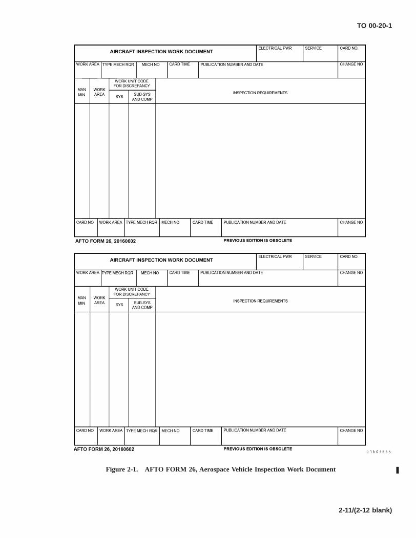
Figure 2-1. AFTO FORM 26, Aerospace Vehicle Inspection Work Document
TO 00-20-1
2-11/(2-12 blank)


CHAPTER 3AEROSPACE EQUIPMENT FORMS DOCUMENTATION
3.1 GENERAL.
This chapter prescribes general requirements for aerospace equipment forms. It specifies filing, disposition, and generalmaintenance of forms. For the purposes of the 00-20-series TOs, the term “Documentation” may refer to hard copy forms,computer produced hard copy or Air Force approved electronic databases.
3.1.1 Aerospace Equipment Forms. The following is a brief list of commonly used aerospace equipment forms:
• AFTO FORM 46, PREPOSITIONED AIRCREW FLIGHT EQUIPMENT (computer generated authorized)
• AFTO FORM 95, SIGNIFICANT HISTORICAL DATA
• AFTO FORM 244/245, INDUSTRIAL SUPPORT EQUIPMENT RECORD
• AFTO FORM 427, AEROSPACE VEHICLE INTEGRAL FUEL TANK REPAIR HISTORICAL DATA
• AFTO FORM 428, B-1B AIRCRAFT INTEGRAL FUEL TANK REPAIR HISTORY RECORD
• AFTO FORM 781, ARMS AIRCREW MISSION FLIGHT DATA DOCUMENT
• AFTO FORM 781A, MAINTENANCE DISCREPANCY AND WORK DOCUMENT
• AFTO FORM 781B, COMMUNICATION SECURITY EQUIPMENT RECORD
• AFTO FORM 781C, AVIONICS CONFIGURATION AND LOAD STATUS DOCUMENT
• AFTO FORM 781E, ACCESSORY REPLACEMENT
• AFTO FORM 781F, AEROSPACE VEHICLE IDENTIFICATION DOCUMENT
• AFTO FORM 781G, GENERAL MISSION CLASSIFICATIONS-MISSION SYMBOLS
• AFTO FORM 781H, AEROSPACE VEHICLE STATUS AND MAINTENANCE DOCUMENT
• AFTO FORM 781J, AEROSPACE VEHICLE-ENGINE FLIGHT DOCUMENT
• AFTO FORM 781K, AEROSPACE VEHICLE INSPECTION, ENGINE DATA, CALENDAR ITEM INSPEC-TION, AND DELAYED DISCREPANCY DOCUMENT
• AFTO FORM 781P, SUPPORT GENERAL DOCUMENTATION RECORD
• DD FORM 1896, DOD JET FUEL IDENTAPLATE
• DD FORM 2026, OIL ANALYSIS RECORD
3.2 MAINTENANCE INFORMATION SYSTEMS (MIS).
MIS refers to automated maintenance information systems that support and enable maintenance business processes. MIS isused to document maintenance actions and track fleet health. MIS includes Integrated Maintenance Data Systems (IMDS),Reliability and Maintainability Information System (REMIS), G081/Mobility Air Force Logistic Command Control (G081/MAF LOG C2), Comprehensive Engine Management System (CEMS), Precision Measurement Equipment Laboratory(PMEL) Automated Management System (PAMS), Flight Equipment Records Management System (FERMS), Defense
TO 00-20-1
3-1

Property Accountability System (DPAS), Defense Repair Information Logistics System (DRILS), and Reliability, Availabil-ity, Maintainability Logistics Support System for Pods (RAMPOD). These systems must be developed and used meeting theintent of documentation requirements contained in this publication. Use of systems other than those listed above requireMAJCOM/Lead Command and AF/A4F and/or A4N approval. REMIS is the system of record for all maintenance datadocumentation.
NOTE
EXCEPTION: F-22 Integrated Maintenance Information System (IMIS) and F-35 Autonomic Logistics Informa-tion System (ALIS) will utilize embedded electronic forms capabilities in accordance with applicable TOs. F-22IMIS is the MIS of entry, IMDS facilitates all scheduling functionality. F-22 IMIS users and managers will ensureIMDS accurately reflects documentation in F-22 IMIS.
3.3 AUTOMATED FORMS.
When MISs are available, automated forms will be used, ensuring latest version of form is utilized via e-Publishing website.The e-Publishing website serves as the official repository for departmental, command, and field publications and forms. As aminimum, AFTO Forms 781A, 781J, 781K, and 95s generated by the MIS will constitute fully automated forms.
NOTE
EXCEPTION: F-22 IMIS and F-35 ALIS utilize embedded forms capabilities.Manual forms produced by a com-puter program do not meet the intent of automated forms. Use of computer generated AFTO Form 46 is autho-rized. Other automated products may be used for process controls and/or AFTO Form 244/245 documentation(e.g. Process Control Automated Management System (PCAMS)). Permanently grounded Ground InstructionalTraining Aircraft (GITA) are not required to use automated forms.
3.4 FORMS ENTRIES.
Entries on maintenance documents will be printed except when a written minimum signature is required. Documentation willbe legible and complete. Entries on maintenance documents will be made in black (pencil, ball point pen, stamp or pre-printed stickers/labels), unless otherwise specified. Abbreviations may be used for any word or term frequently used inmaking entries on documents.
3.5 STANDARD DATE FORMAT.
Manually record all dates on the forms prescribed in the 00-20-series TOs by eight digits in the order of year, month, andday. Example: YYYYMMDD, 20091207 for 7 Dec 2009.
3.6 MINIMUM SIGNATURE.
3.6.1 Maintenance. The minimum signature for maintenance document purposes required by the 00-20-series TOs con-sists of the first name initial, last name (not necessarily in this order), and employee number (omit employee number fromsignature if form has specified block for employee number), or USERID or equivalent Federal Aviation Administration(FAA) certification number. Electronic signatures may be used in lieu of these requirements.
3.6.2 Aircrew. Minimum signature for aircrews consists of the first name initial, last name (not necessarily in this order)and when applicable, crew position. For Mobility Air Forces (MAF) units, add flying squadron number, i.e., 00022 for 22ASor 00319 for 319AS. For RPA units, crew position is required. Electronic signatures may be used in lieu of these require-ments.
3.6.3 Contractors. Contractors/ALCs may use a production stamp.
3.7 INFORMATIONAL NOTES.
Informational notes are informative in nature and do not affect the safety or reliability of the aerospace equipment, thereforethese entries do not require symbols, job control numbers or entry in the MIS. Informational notes will not include non-valueadded entries (such as statements that inform aircrews of crew chief names, where trash bags are located, statements askingthe aircrew to keep the aerospace equipment clean, etc.). For each entry, write the words “INFO NOTE” in the DISCREP-ANCY block of the AFTO Form 781A or AFTO Form 244/245 (or electronic equivalents) followed by the applicable
TO 00-20-1
3-2

information. When any of the information becomes invalid, line through the invalid information only. Informational noteswill be transcribed in the same manner as all other discrepancies. For electronic forms, clear the write up if needed and/orre-enter the info note in a new discrepancy block.
3.8 TRANSFER OF DOCUMENTS.
3.8.1 Losing Organization. When aerospace equipment is transferred to another organization, the losing maintenance orsupply supervisor, will ensure all current and historical maintenance documents or computer generated equivalents accom-pany the equipment or are forwarded to the new activity not later than the same day the transfer is affected. Waterproofenvelopes will be securely attached to the item in a location that will provide the best protection from exposure to elementsand prevent loss during handling. Electronic transfer is preferred. See Chapter 8 for more specifics on transfer of aerospacevehicles.
NOTE
EXCEPTION: Transfer of F-22 IMIS and F-35 ALIS electronic documentation is facilitated by contracted systemadministrators and Plans, Scheduling, and Documentation (PS&D).
3.8.2 Gaining Organization. When equipment is received and historical documents are missing or contain incompleteinformation, the gaining organization will immediately notify the losing organization. When documents cannot be located,contact the applicable SM for disposition instructions with an information copy to the MAJCOM.
3.9 FILING.
File and dispose of all forms IAW AFMAN 33-363.
3.9.1 Historical File. Establish and maintain historical files, in accordance with AFMAN 33-363 and AFI 21-101 for eachaerospace vehicle or equipment. The historical file may include hard or electronic copies. Computer generated forms in thesefiles may contain a difference in format, but must contain all required information. Examples of documents in a historical fileare, but not limited to:
• AFTO Form 781 series
• AFTO Forms 95, 244/245, and 427 or 428
• Non-Destructive Inspection (NDI) records (i.e., resume reports, x-ray films, etc.)
• Functional check flight checklist/worksheets
• Egress records
• Weight & Balance records
• Major Inspection packages
• Aircrew Flight Equipment records
• Fuel records
3.10 DISPOSITION.
3.10.1 Forms and Documents. Dispose of all forms IAW AFMAN 33-363 and this TO.
3.10.1.1 When an ICBM is expended or destroyed, forward historical documents to the SM within 10 working days afterthe occurrence. In the event an accident investigation board, not related to AFI 51-503, impounds documents of an ICBM,forward the documents to the SM within ten working days after release from the board. Forward historical documents forreentry vehicles or systems to the 526 ICBM Systems Group, Hill AFB, Utah. This paragraph does not apply to expendeddrones.
TO 00-20-1
3-3

3.10.1.2 Disposal of documents for aerospace vehicle or missiles that are involved in accidents or incidents which resultin damage to private property, loss of life or serious injury to personnel, is directed in AFMAN 33-363.
3.11 EXTENDED STORAGE DOCUMENTATION.
3.11.1 Maintaining Documents. Documentation of aerospace equipment in extended storage will be maintained in theappropriate activity, or MIS IAW TO 1-1-17 or other directives. Update maintenance and historical files for aerospaceequipment being returned to service.
3.11.1.1 While aerospace equipment is in extended storage, the responsible activity will record all applicable TCTO,special inspections, etc., released during the storage period. Engine or equipment containers need not be opened solely tomake entries on maintenance or historical documents.
3.11.1.1.1 For other packaged equipment, post these entries on the applicable condition tag, or attach label to the item orcontainer for subsequent transfer to the maintenance and historical files. Forward the Engine Configuration ManagementSystem (ECMS)/TCTO data reflecting current applicability.
3.11.1.2 When aerospace equipment is removed from storage, the removing organization will review MIS TCTO data, ormaintenance and historical documents. This is required to ensure they are current and all outstanding TCTOs, specialinspections, etc. are recorded on the applicable forms.
3.11.1.3 When aerospace equipment is maintained in extended storage at an organization or activity, in accordance withTO 1-1-17 or other directives, the GP/CC may request a waiver from the TCTO manager on a case-by-case basis. Maintainall active waivers in the aerospace vehicle forms binder. File in the equipment’s historical documents when no longer active.
3.12 AIR CARD/FUEL IDENTIPLATE.
Each USAF aerospace vehicle will carry an Aviation Into-plane Reimbursement Card (AIR Card) and/or DD Form 1896, JetFuel Identiplate, GP/CC selects a suitable location aboard each assigned MDS.
NOTE
The requirement to carry an Air Card/Fuel Identiplate on each aerospace vehicle does not apply to MQ-1 andMQ-9 aircraft.
3.13 USE OF USAF AEROSPACE VEHICLE BY BAILMENT CONTRACTORS AND AIR CARRIER CON-TRACT OPERATORS.
3.13.1 Requirements. Bailment contractors and air carrier contract operators utilizing USAF aerospace vehicles willmaintain the AFTO Form 781J and AFTO Form 95 historical documents.
3.13.1.1 With AF/A4LM consent, use of other AFTO Form 781 series forms is not required provided substitute forms ordocuments are utilized to accomplish the intent of these forms.
3.13.1.2 When an aerospace vehicle is returned to an Air Force installation, the bailment contractor or air carrier contractoperator will return the forms and make the final entries on the AFTO Form 781 series forms and AFTO Forms 95 inaccordance with this TO and TO 00-20-2.
3.13.1.3 Since all Air Force information may not be available to the contractors; the Air Force organization receiving theaerospace vehicle will take necessary action to complete the documents or initiate new forms.
3.14 PROCESSING OF DOCUMENTS DURING DEPOT MAINTENANCE.
3.14.1 Depot Maintenance Instructions. When a depot receives an aerospace vehicle, the depot will accomplish thefollowing:
TO 00-20-1
3-4
3.14.1.1 Debrief the aerospace vehicle into depot using AFTO Form 781 series forms. Enter discrepancies from debrief inthe AFTO Form 781A and carry them forward to Work Control Documents (WCDs). To transfer discrepancies to a depotWCD, the corrective action block of the AFTO Form 781A must reference the WCDs used to close the discrepancy. Thedepot will transfer each open discrepancy to WCD and enter the statement, “Transferred to depot WCD (specify identifica-tion number)” in each corrective action block and enter date and minimum signature.
NOTE
• EXCEPTION 1: Fifth generation aircraft (ex. F-22, F-35) that utilize embedded electronic forms will not closetheir respective AFTO Forms 781. These aircraft use fifth generation Maintenance Information Systems withembedded 781 series forms that must remain open and operational for any maintenance to be performed.
• EXCEPTION 2: Depot maintenance organizations conducting short-term modifications (30 planned-days orless) are not required to carry forward discrepancies not affecting modification completion or inspections notdue or becoming overdue during aircraft possession. If this exception is utilized, depot organizations mustcomplete the following actions:
3.14.1.1.1 A single RED X symbol will be entered or transferred into the AFTO Forms 781A to document the modifica-tion to be performed. No concurrent maintenance will be accomplished during this modification unless previously agreedwith MXG/CC approval and the Depot team.
3.14.1.1.2 A Production Planning Team (PPT) meeting will be held with the following skill sets in attendance: Planner,Production, QA, Safety, and Engineering. Each PPT member will be part of the forms review process to identify discrepan-cies that affect planned modification at aircraft induction and transfers those discrepancies to WCDs. (Paragraph 3.14.1.1).
3.14.1.1.3 Planner will document PPT review on the modification process using applicable planning documents andforward for PPT coordination.
3.14.1.1.4 In addition to transferring those discrepancies affecting the modification, all Red X discrepancies will betransferred to WCDs.
3.14.1.1.5 Modification will be accomplished using WCDs, to include all over and above (O&A) workload.
3.14.1.1.6 After completion of all required modification work, any open WCDs will be transferred to AFTO Forms 781A.
3.14.1.1.7 Modification will be signed off in the AFTO Forms 781A.
3.14.1.1.8 All Historical data will be listed on AFTO Form 95 after completed modification.
3.14.1.1.9 At a minimum, QA will perform a Quality Verification Inspection “Q” Stamp (QVIQ) of the first completedmodification to verify process met established criteria. Ensure process deficiencies are reported to the MXG/CC for finaldispensation.
3.14.1.2 Transfer all AFTO Form 781K discrepancies, and inspections to be completed, coming due or will becomeoverdue during depot to WCDs during possession. Enter the statement, “All preceding open discrepancies and applicableinspections transferred to depot WCD (specify identification number)” after the last entry. Follow the statement with the dateand minimum signature of a production inspector or a representative of the depot documentation activity. All inspections notcarried forward to WCDs will remain in the AFTO Forms 781K. The end result must be a complete audit trail in the AFTOForm 781 series forms.
3.14.1.3 The depot WCD will contain, (1) open discrepancies that appear on the maintenance documents which accom-pany the aerospace vehicle, (2) each TCTO scheduled for accomplishment and (3) an identification of any special require-ments or special projects. Document all work performed by depot personnel on applicable depot WCD.
3.14.1.4 Depots will reconcile all WCDs prior to aerospace vehicle -6 TO pre-flight transfer to flight test aircrew. At thistime, initiate new AFTO Form 781 and transfer all open WCD discrepancies to reflect current aerospace vehicle status. Allmaintenance actions will then be documented on AFTO Form 781 to provide a maintenance audit trail and depot WCDs toensure maintenance action approval, tech data and material availability, and financial accounting.
TO 00-20-1
3-5

3.14.1.5 Return the closed out AFTO Form 781 and a copy of the closed out depot package to the owning organization. Ifavailable, the unit may request an electronic copy of the depot package instead. Return all AFTO Form 95s to the owningunit with the following: (1) part numbers and serial numbers for all serially tracked items and include Date of Manufacture(DOM) and Date of Installation (DOI), (2) TCTOs, (3) Time Change Item (TCI), (4) Equipment Transfer Report (ifavailable), (5) special or scheduled inspections (with the date and aerospace vehicle time they were accomplished), (6) andany other significant information. All serially controlled items, warranty items, TCIs, inspections and other events listed inParagraph 9.1.1.3 will be entered into REMIS prior to transfer.
3.15 SAFEGUARDING/DOCUMENTING CLASSIFIED EQUIPMENT.
When an aerospace vehicle has equipment or documents classified confidential or higher, installed or carried aboard, docu-ment as follows: electronically format on the AFTO Form 781B or on a Placard (placed in front of the AFTO Form 781F)the assigned security classification and the equipment or documents by their title or nomenclature unless this information isclassified. Stamp or mark this information in an easy to see manner, such as a red border, to ensure that the form and theclassification are immediately apparent. This form will not indicate the reason the aerospace vehicle is classified. Addition-ally, document all installed Communications Security (COMSEC) equipment IAW Paragraph 5.8.
TO 00-20-1
3-6

CHAPTER 4SYMBOLS AND THEIR USE
4.1 GENERAL.
4.1.1 Symbols. The symbols described in this chapter are established for use on maintenance documents to make impor-tant notations instantly apparent. They indicate the condition, fitness for flight or operation, servicing, inspection, andmaintenance status of the aerospace vehicle or equipment. The Red X represents the most serious possible condition. TheRed W (ICBM only) is the next most serious condition, the Red Dash the next most serious, and the Red Diagonal the leastserious condition. Computer-generated forms symbols, that are printed in black, must be overwritten in Red.
4.2 RED X.
4.2.1 Usage. A Red X indicates that the aerospace vehicle, equipment or SE is considered unsafe or unserviceable andwill not be flown or used until the unsatisfactory condition is corrected and/or the symbol is cleared. No one will authorizeor direct an aerospace vehicle to be flown, a missile to be launched or equipment to be used until the Red X has beenproperly cleared in accordance with applicable technical data.
NOTE
EXCEPTION: Aerospace vehicle, equipment or SE with a Red X condition may be operated (but not flown ortaxied at high speed) as necessary to troubleshoot or repair the discrepancy.
4.2.1.1 When a Red X is applied, maintenance personnel authorized to clear a Red X will inspect the work performed tocorrect the discrepancy and validate all related discrepancies for completeness and accuracy.
4.2.1.2 Use a Red X (not all inclusive):
4.2.1.2.1 When aerospace equipment is considered unsafe, unserviceable or non-airworthy, or unknown status/lack ofaccountability of special inspection/time change item requirements has been identified.
NOTE
EXCEPTION: Dash 21 Equipment normally installed for ground handling addressed in pre-launch workcards/checklists do not require Red X documentation (e.g. pitot covers, gear pins, engine plugs/covers/fan stops, canopystruts, and intake inspection mats).
4.2.1.2.2 Upon receipt of an immediate action TCTO or commercial service bulletin equivalent.
4.2.1.2.3 After expiration of a TCTO or commercial service bulletin equivalent compliance period.
4.2.1.2.4 When work is started on urgent action and safety TCTOs or commercial service bulletin equivalent.
4.2.1.2.5 When an egress final is required.
4.2.1.2.6 When installed AFE inspections are overdue.
NOTE
• EXCEPTION: Those item(s) overdue while an aerospace vehicle is on alert status, away from home stationwithout AFE inspection capability or not required for safe flight or operation (such as when life rafts areoverdue but no over water mission is scheduled), this does not include Functional Check Flight (FCF) at Depotlocations. These are placed on a Red Dash until the aerospace vehicle goes off alert status, returns to homestation or AFE mission requirements change.
• Do not use exception above as a planning factor to allow aircraft to depart home station with overdue AFE.
TO 00-20-1
4-1

4.2.1.2.7 When time change AFE components/life sustaining items are overdue.
NOTE
• EXCEPTION: Those item(s) overdue while an aerospace vehicle is on alert status or away from home stationwill be placed on a Red Dash until the aerospace vehicle goes off alert status or returns to home station.
• Do not use the exception above as a planning factor to allow aircraft to depart home station with overdue AFEtime change components/items.
4.2.1.2.8 When a major scheduled inspection (e.g. ISO, PH, PE, PDM) has started on aerospace equipment.
4.2.1.2.9 When a scheduled inspection renders the aerospace equipment unsafe or unserviceable.
4.2.1.2.10 Inspections not completed by the next scheduled major inspection (Periodic, isochronal, phase, HSCs, HPOs,and commercial equivalent inspections) will be upgraded to a Red X. Exception: Maintenance and inspection requirementson Munitions Materiel Handling Equipment (MMHE) and Support Equipment identified in the Master Nuclear CertificationListing must be completed no later than the maximum interval specified in the item specific technical order. For guidance oninspection and maintenance intervals on nuclear weapons test and handling equipment refer to 11N-35-51. For Cryogenicsequipment, follow the applicable guidance as outlined in 37C2-series technical orders. This paragraph does not apply toICBMs.
4.2.1.2.11 When aerospace vehicle weight and balance is unknown.
4.2.1.2.12 To indicate a Foreign Object (FO) inspection is required when maintenance has been performed in or aroundthe air intake or exhaust areas of jet or gas turbine engines.
NOTE
Workcard and TO inlet and exhaust inspections (e.g. PR/BPO/TH) do not require a Red X entry.
4.2.1.2.13 When impounding aerospace equipment.
4.2.1.2.14 When the removal and/or replacement of any component or assembly is such that improper removal and/or re-installation would affect safety of flight or safe operation of the equipment.
4.2.1.2.15 When loading software into MDS Minimum Equipment List (MEL) and/or Minimum Essential Subsystem List(MESL) required components/systems.
4.2.1.2.16 Overdue washes, in accordance with TO 1-1-691 or weapon system specific TO, without approved waiver.
4.3 RED DASH.
4.3.1 Usage. The presence of the Red Dash symbol indicates the condition of the equipment is unknown and a moreserious condition may exist.
4.3.1.1 Use a Red Dash: (not all Inclusive)
4.3.1.1.1 When an accessory replacement, operational check, cure check or FCF is due.
4.3.1.1.2 When an aerospace equipment inspection is due IAW applicable -6 TO or equipment manual. This inspectionmust be accomplished as soon as the condition preventing its completion no longer exists, but no later than during the nextscheduled major inspection (e.g. ISO/PH/180-Day or equivalent). For cryogenics equipment, follow the applicable guidanceoutlined in 37C2-series technical orders.
NOTE
EXCEPTION: The inspection will not be postponed if prohibited by applicable -6 TO or equipment manual. SeeParagraph 4.2.1.2.10.
TO 00-20-1
4-2
4.3.1.1.3 When Alternate Mission Equipment (AME)/Normally Installed Equipment (NIE) is due a scheduled inspection.This equipment must only be flown in an unarmed, unused configuration when a scheduled inspection is due.
4.3.1.1.4 When portions of an inspection are not accomplished due to lack of parts, test equipment etc., unless prohibitedby the -6 or other applicable TOs.
4.3.1.1.5 When an aerospace vehicle is due PDM. After 90 days, upgrade the Red Dash to a Red X, unless an extensionhas been obtained from the appropriate SM.
4.4 RED DIAGONAL.
4.4.1 Usage. The Red Diagonal indicates that a discrepancy exists on equipment, but is not sufficiently urgent or danger-ous to warrant its grounding or discontinued use.
4.4.1.1 The Red Diagonal will be a straight line from the lower left to the upper right corner of the SYM block.
4.4.1.2 Use a Red Diagonal (not all inclusive).
4.4.1.2.1 Upon receipt of an urgent action or Category I, routine action safety modification TCTO or commercial equiva-lent.
4.5 CLEARING RED SYMBOLS.
4.5.1 Requirements. Individuals who sign off a Red symbol for a specific maintenance task must be qualified/certified (ifapplicable) for the task.
4.5.1.1 Inspectors who are authorized to clear Red X symbols will enter their last name initial in black over the symbol inthe SYM block and their minimum signature in the INSPECTED BY block provided that another member of the mainte-nance crew accomplishing the work signs the CORRECTED BY block with their minimum signature. This maintenancecrew member must be involved in the work required to complete the task. In addition, the inspector who signs the IN-SPECTED BY block must have the opportunity to verify the correct completion of the work.
4.5.1.2 When aerospace equipment is placed on a Red X for accomplishment of an inspection/impoundment and warningtags, the Red X is cleared by an inspector who will enter a statement in the CORRECTIVE ACTION block indicating therequired inspection has been accomplished in accordance with the applicable technical order. The inspector will enter his/herminimum signature in the INSPECTED BY and EMPLOYEE NUMBER blocks and initial over the symbol in the SYMblock. The CORRECTED BY block will be left blank.
4.5.1.3 Red dash discrepancies are signed off by the individual who accomplishes the inspection/corrective action byentering their last name initial in black over the symbol in the SYM block and their minimum signature in the INSPECTEDBY block.
4.5.1.4 Red diagonal discrepancies are signed off by the individual who accomplishes the corrective action by enteringtheir last name initial in black over the symbol in the SYM block and their minimum signature in the CORRECTED BYblock.
4.5.1.5 When operations are conducted in locations where qualified maintenance personnel are not available, the homestation GP/CC will designate an individual to sign off the Red X. The designated individual at the location may accomplishthe required work and clear the Red X by entering their minimum signature in the CORRECTED BY block, initialing theINSPECTED BY block, and placing their last name initial over the symbol. In the corrective action block, annotate the nameof the GP/CC and the specific repair action taken so the data can be entered into the appropriate MIS.
4.5.1.6 When aerospace equipment is in an unserviceable or unsafe condition and a Depot Field Team or Contract FieldTeam (DFT/CFT) has been dispatched, the chief of that team will clear the Red X for only the work the team has corrected,if specifically authorized by the dispatching organization.
TO 00-20-1
4-3

4.6 CHANGING SYMBOLS AFTER AN ORIGINAL ENTRY.
4.6.1 Requirements. Entry of Red symbols on an AFTO Form or equivalent by an individual represents his/her assess-ment of the seriousness of the defect. Therefore, no individual will be directed to change a symbol that has been entered.
NOTE
If any Red diagonal or Red dash is being upgraded, ensure the original information in the DISCREPANCY blockis not altered or added to in any way.
4.6.1.1 Any person who determines a Red diagonal is more serious than previously entered may upgrade that symbol bydrawing a line through the minimum signature and employee number of the person who made the entry. Enter their ownminimum signature and employee number directly above the lined out minimum signature and employee number (DISCOV-ERED BY block). Draw a red straight line from the upper left corner to the lower right corner to indicate a Red X condition.
4.6.1.2 When a Red Dash is upgraded to a Red X, the individual will close out the original Red Dash with the remark“Symbol upgraded to a Red X, see page ___, item ___” in the CORRECTIVE ACTION block. Enter their own minimumsignature and employee number in the INSPECTED BY block and place their last name initial over the Red Dash. Reenterthe original discrepancy on a Red X in the next open DISCREPANCY block reflecting the minimum signature and employeenumber of individual upgrading the discrepancy in the DISCOVERED BY block.
4.6.1.3 If any supervisory personnel believe the condition is less serious than represented by the symbol, the matter willbe brought to the attention of the GP/CC, equivalent contractor representative or any personnel specifically authorized by theGP/CC to downgrade Red X or W entries. If the symbol is downgraded, the authorized individual who made the decisionwill annotate their action in the CORRECTIVE ACTION block for the particular defect. This entry will read as follows:“Symbol downgraded from a Red X to a Red Diagonal. Reentered see page ____, item ____.” Individuals who enter theremark assume responsibility for their action by initialing over the symbol and entering their minimum signature in theINSPECTED BY block. Reenter the same entry for the discrepancy, the new symbol, and the printed minimum signature ofthe person originally discovering the discrepancy in the next open block of the applicable AFTO Form or equivalent andinclude an entry to read essentially as follows: “Symbol downgraded from a Red X to a Red Diagonal on (date) by(employee minimum signature) see page ____, item ____.” This entry remains with the discrepancy until it is corrected.
4.6.1.4 To defer accomplishment of an immediate or urgent action TCTO or commercial equivalent, submit requests to theSM, through the MAJCOM. When waiver/deferral of a TCTO or commercial equivalent is approved downgrade the Red Xto a Red Dash symbol in accordance with this TO and enter a brief statement of reason for noncompliance with the TCTOon the applicable forms. Upon termination of the condition that required the use of the waiver, the Red Dash symbol will beupgraded to a Red X.
4.6.1.5 Symbols/initials once entered in the aircraft forms will never be erased. Erroneous MIS entries (computer gener-ated entries) related to scheduled maintenance (special inspection, time changes, and TCTOs) will be corrected per theparagraphs below but WILL NOT be signed off in MIS as erroneous. Instead, delete these entries in the MIS per Paragraph4.6.1.5.5 and manually correct the aircraft forms. Correct ALL erroneously entered symbols/initials as follows:
4.6.1.5.1 When a Red symbol is entered in error, the individual discovering the incorrect entry will enter the statement inthe CORRECTIVE ACTION block: “Symbol entered in error, discrepancy and correct symbol reentered on page ____, item____” or “Symbol entered in error, no discrepancy exists,” and enter their minimum signature requirements in the COR-RECTED BY or INSPECTED BY blocks as applicable and initial over the symbol. If the symbol entered in error is a RedX, the authorized individual who signs off the incorrect symbol must follow the procedures stated in the next paragraph.
4.6.1.5.2 When a Red X or a Red W is entered in error, the individual discovering the incorrect entry will enter theapplicable statement identified in the previous paragraph. If they are authorized to clear these symbols, they will completethe INSPECTED BY block and initial over the symbol. If they are not authorized to clear these symbols, they will enter theirminimum signature in the CORRECTED BY block. An individual authorized to clear these symbols, initials over the symboland completes the INSPECTED BY block. This procedure will NOT be used to circumvent downgrade procedures.
TO 00-20-1
4-4
4.6.1.5.3 When an initial is entered in error, the individual discovering the incorrect entry will enter the statement in theCORRECTIVE ACTION block “Initial entered in error, discrepancy reentered on page_____, item_____.”
NOTE
Do not place an additional initial over the symbol.
4.6.1.5.4 When a discrepancy is entered in error, the discrepancy will not be erased or changed by anyone other than theoriginator. The individual discovering the incorrect entry will enter “Discrepancy entered in error” and clear the discrepancyper Paragraph 4.6.1.5.1 or Paragraph 4.6.1.5.2.
4.6.1.5.5 When erroneous MIS entries created by Scheduling are entered, they must be deleted, and not signed off asentered in error. This is to avoid inadvertent advancement of the due date/time for special inspections, time change items orerroneous completion of TCTOs. These entries have a type interval indicator or data code in the MIS and are unique to othermaintenance entries. Clearing these discrepancies as entered in error will advance the due date and reflect completionregardless of corrective action comments. Notify Plans and Scheduling and/or the appropriate computer system administratorto delete these discrepancies when deletion is necessary to ensure inspections and time change due dates/time and TCTOcompletion are properly managed.
4.7 DOWNGRADING A RED X FOR ONE-TIME FLIGHT.
4.7.1 Requirements. An aerospace vehicle with a Red X condition may be released for a one-time flight provided theaerospace vehicle is or can be made airworthy under tightly controlled and specified operating conditions. Such action mustbe authorized by the owning GP/CC or designated official, the SM or through the on-site chief of an AFMC repair team(when aerospace vehicle is possessed by AFMC). Aircraft under the operational control of an Area of Responsibility (AOR)GP/CC are owned by that GP/CC for the period of deployment. Aircraft transiting through an AOR, and not under theoperational control of that AOR, are still owned by the home station GP/CC. For example, F-16s deployed to Balad areowned by Balad GP/CC; however, a C-5 transiting through Balad is owned by the home station GP/CC. The followingAFTO FORMs 781A and 781H documentation are required to downgrade a Red X and release the aerospace vehicle for aone-time flight.
4.7.1.1 To downgrade a Red X on the AFTO Form 781A, the GP/CC or designated official enters the following statementin the CORRECTIVE ACTION block, “Red X changed to a Red diagonal (see page ___, item ___) for the purpose of aone-time flight to (name destination station)” and if applicable, “with an enroute stop at (name station).” This individual willalso enter their minimum signature in the INSPECTED BY block and initial over the symbol in the SYM block with theirlast name initial.
4.7.1.1.1 If a downgrading official is not available to sign the INSPECTED BY block, continue the CORRECTIVEACTION statement: “One-Time flight authorized by (name, rank, title, organization).” The on-site person, authorized by thedowngrade official, will downgrade the Red X by placing their minimum signature in the INSPECTED BY block andinitialing over the symbol in the SYM block.
4.7.1.2 In the next open block of the AFTO Form 781A, enter a Red Diagonal in the SYM block and current date inDATE DISC block. In the DISCREPANCY block, enter the original discrepancy with a descriptive statement of temporaryrepair or inspection accomplished to make the aerospace vehicle airworthy for one-time flight. Also, enter restrictions tonormal flight operation of systems and/or equipment, such as gear operation, pressurization, altitude or airspeed limits, etc.Print the minimum signature in the DISCOVERED BY block (normally, the same person that downgraded the Red X).
4.7.1.3 When the aerospace vehicle arrives at the destination, the Red Diagonal will be upgraded to a Red X.
4.8 RED W (ICBM ONLY).
4.8.1 Requirements. A Red W symbol for ICBMs is used to reflect a condition of Aerospace Vehicle Equipment (AVE),SE or Real Property Installed Equipment (RPIE) that is inoperative for its intended use and requires careful attention becauseof a condition:
4.8.1.1 At a missile site that will not prevent successful launch, flight impact or command and control of the launch orflight.
4.8.1.2 Off site that will not prevent the operation of a major end item of powered or non-powered SE.
TO 00-20-1
4-5

4.8.1.3 At a missile trainer that will not prevent its operation.
4.8.1.4 The inoperative equipment will not be used for its intended purpose until the malfunction, unsatisfactory or unsafecondition is corrected and the item can be used without further damage to equipment or injury to personnel.
4.8.1.5 Once the Red W is entered, it will be treated the same as a Red X for clearing actions.
4.9 RED C.
4.9.1 Requirements. Use a RED C in the Symbol block to indicate that the equipment has been contaminated by achemical, biological, radiological agent or infestation (e.g. Insects, rodents).
4.9.1.1 A Red C indicates that an aerospace vehicle has been contaminated with chemical, biological, radiological con-taminants or an infestation. The Red C discrepancy should note the highest level of contamination, type of contamination orinfestation, and minimum personal protective equipment (PPE) requirements for operation and maintenance of aerospacevehicles. These conditions will be determined by installation Bioenvironmental Engineering Office.
4.9.1.2 A Red C will never denote an aerospace vehicle or SE as unsafe to utilize or perform maintenance on. The Red Cis a means of recording events of aerospace vehicle or SE contamination or infestation. This discrepancy should never beremoved from the aerospace vehicles forms until the vehicle has been deemed safe to work on or around without the use ofadditional PPE as stated in the discrepancy. Red Cs will only be cleared by authorization of the Installation Bioenvironmen-tal Engineering Office.
4.9.1.3 A Red C will not status an aircraft as it does not impact its ability to accomplish a mission.
4.9.1.4 The Red C will be cleared the same as a Red X as directed in Paragraph 4.5.1.2. CORRECTIVE ACTION blockwill include highest level of contamination, post decontamination at sign off, name of individual from installation Bioenvi-ronmental Engineering Office that cleared the aircraft, and an applicable statement clearing the aerospace vehicle. Forexample, “Aircraft Contamination reduced to acceptable levels” or “Aircraft infestation eliminated.”
4.9.1.5 Enhanced local procedures may be developed by utilizing the MDS-specific technical data and approved byGP/CC.
TO 00-20-1
4-6

CHAPTER 5AFTO FORM 781 SERIES
5.1 GENERAL PURPOSE OF AFTO FORM 781.
Use the AFTO Form 781 series collectively to provide a maintenance, inspection, service, configuration, status, and flightrecord for the particular aerospace vehicles and trainers for which they are maintained. There may be slight differencesbetween the forms provided as examples in this TO and the forms available from the Maintenance Information System(MIS) and AF Publishing website or the electronic versions. If the MIS is available, it will be used; if the MIS is notavailable, the version on the web will be used. Supervisors will ensure current forms are being used, and entries on theseforms are accurate. Prior to flight, the aircrew will review the AFTO Form 781 series forms for aerospace vehicle status.Prior to maintenance, technicians will review the AFTO Form 781 series forms. Use the 24-hour military clock format whenrecording time entries in all forms. Forms binders must be standardized at unit level.
5.2 TRAINING DEVICE FORMS.
5.2.1 Mandatory AFTO Forms. The AFTO Forms 781, 781A, 781F, 781H, and 781K are mandatory for trainers in the6930 Federal Stock Class (FSC), as well as private company owned training devices used by USAF flight crews, GP/CCsmay approve the use of additional AFTO Form 781 series forms for this FSC. Accomplish documentation for visual systemslisted in FSC 6930 on the forms of the simulator to which they are attached. GP/CCs may opt to use any AFTO Form 781series forms with other FSC trainers.
5.2.1.1 When documenting the AFTO Form 781 series forms, precede the MDS of the aerospace vehicle being simulatedby the letter S to denote a specific aerospace vehicle trainer MDS.
5.3 AEROSPACE VEHICLE FORMS.
5.3.1 Mandatory AFTO Forms. The AFTO Forms 781, 781A, 781F, 781H, and 781K are mandatory for aerospacevehicles. GP/CCs may approve the use of additional AFTO Form 781 series forms.
5.3.2 Forms Binder. Aerospace vehicle forms are maintained in a forms binder. Arrangement of forms in the binder areas follows: AFTO Forms 781F, 781B (if used), 781, 781H, and 781A in that order. The GP/CC will determine standardizedarrangement of all other forms as long as they are arranged after the AFTO Form 781A.
NOTE
• During deployment or contingency operations where the potential for battle damage exists, the AFTO Form97/97A will be added to the forms binder.
• The requirement for systems coded aerospace equipment to carry a 781J does not apply to Ground ControlStations (GCS). The GCS does not have an engine, therefore has no engine data to track.
5.4 DOCUMENTING OPERATIONAL CHECKS AND FUNCTIONAL CHECK FLIGHTS (FCF).
5.4.1 Requirements. FCFs and Operational Checks, to include leak checks, rig checks, and cure checks, must be enteredon the AFTO Form 781A and documented as follows:
5.4.1.1 Operational Checks. When required, an operational check/stray volt check will be part of the maintenanceaction. Document in the CORRECTIVE ACTION block by including a statement such as “OP CK GOOD” or “Stray VoltCheck Good.” If a malfunction is detected during the check, document the finding (for example, sign off the write-up as “OPCK BAD” or “Stray Volt Check Bad”) and refer to a new write-up documenting the malfunction under the appropriatesymbol.
TO 00-20-1
5-1

5.4.1.1.1 In the event that the operational check cannot be accomplished concurrently with or immediately after comple-tion of the maintenance, close out the original entry by describing the corrective action with a statement that an operationalcheck is required. When this situation occurs, make a new entry for the operational check in the next open block on theAFTO Form 781A.
5.4.1.1.2 The original entry CORRECTIVE ACTION and the new “OPERATIONAL CHECK” entry must refer to eachby entering “See JCN” and/or “See page _____ and item _____.” The operational check entry must adequately describe thereason for the operational check with the prescribing TO number recorded.
NOTE
EXCEPTION: If the operational check Work Center Events/Work Event Separators (WCEs/WESs) are part oforiginal discrepancy and are listed sequentially in the MIS generated AFTO Form 781A, a reference to the originalentry and operational check is not required.
5.4.1.1.3 In-flight operational checks are accomplished at the request of maintenance to validate a maintenance action thatcannot be fully verified on the ground.
5.4.1.1.3.1 When an in-flight operational check is required and does not involve an FCF, make an AFTO Form 781A entryto describe the type and extent of the check needed.
5.4.1.1.4 When an in-flight operational check is good, an aircrew member enters the remark “OP CK GOOD” in theCORRECTIVE ACTION block, enters minimum signature in the INSPECTED BY block and initials over the symbol. Whenan in-flight operational check fails, the aircrew member enters the remarks “OP CK BAD” in the CORRECTIVE ACTIONblock, enters minimum signature in the INSPECTED BY block, initials over the symbol and enters a new discrepancy in thenext open DISCREPANCY block.
5.4.1.2 FCF. Enter the reason the FCF is being accomplished in the DISCREPANCY block.
5.4.1.2.1 After completion of the FCF, if the aerospace vehicle is released, enter the following statement in the CORREC-TIVE ACTION block, “FCF completed, aircraft released for flight.”
5.4.1.2.2 The assigned primary pilot who accomplishes the FCF will initial over the symbol in the SYM block and entertheir minimum signature in the INSPECTED BY block.
5.4.1.2.3 Record discrepancies noted during an FCF performed by depot facility personnel on depot work documents;however, when this option is taken, the AFTO Form 781A will contain a statement reading: “FCF defects recorded on_____” (enter the form 1039 identification).
5.4.1.2.4 For FCFs accomplished after depot work is completed, sign off the AFTO Form 781A entry as “Reported defectscleared on” (enter form identification) and enter minimum signatures in the CORRECTED BY and/or INSPECTED BYblocks. Ensure copies of depot documentation reflecting discrepancies and corrective action accomplished by depot facilitiesduring FCFs accompany the aircraft being returned to the owning command. These documents will be returned to the unitFCF Manager. The documents will then be filed in the historical file and disposed of in accordance with AFMAN 33-363.
5.5 RECORDING ENGINE STORAGE.
When installed engines are placed in storage, make entries on the AFTO Form 781A to indicate the type of storage andwhich portions of TO 2J-1-18 have been complied with. Example: “Engines in storage, TO 2J-1-18, sect par CW.” When theengines are removed from storage status, record a reference to the de-preservation instructions that were used in theCORRECTIVE ACTION blocks. For additional information on assets in extended storage see Paragraph 3.11.
5.6 AFTO FORM 781, ARMS AIRCREW/MISSION FLIGHT DATA DOCUMENT.
(Figure 5-1 and Figure 5-2.) The AFTO Form 781 is the source document for recording individual flying time, sorties and/orevents for input into the MIS and Aircrew Resource Management System (ARMS).
TO 00-20-1
5-2

5.6.1 AFTO Form 781 Documentation Instructions. When available, aircraft with automated flight data recordingsystems will use the total flight time, sortie count, and mods provided by this system for input into the MIS in accordancewith MDS specific guidance established in coordination with Lead Command and aircraft SM.
5.6.1.1 Maintenance or aircrew trainer technician/operator will complete blocks 2 through 5.
a. Block 2, MDS. Enter the MDS designators from block 6 of the AFTO Form 781F.
b. Block 3, SERIAL #. Enter the aerospace vehicle serial number. Example: 85-11428, 65-0966.
c. Block 4, UNIT CHARGED FOR FLYING HOURS. Enter the organization to which the aerospace vehicle is assigned,with the command designation in parenthesis (e.g., 374 AW (AMC). Enter the four-letter code of the Host AviationResource Management (HARM) which services the organization, (supplied by the unit operations officer) to which theoriginal forms must be sent for processing and filing.
d. Block 5, HARM LOCATION. Enter the base to which the aerospace vehicle is assigned.
5.6.1.2 The Aircraft Commander will ensure completion of all other blocks required by AFI 11-401.
5.6.1.3 Remove the completed AFTO Form 781 from the aerospace vehicle forms binder and enter data into the MIS atmaintenance debriefing. Maintenance debrief will complete block 39, MAINT REVIEW to show the form was reviewed andthe data was entered into MIS. Send completed form to unit operations. If aircraft is equipped with automated flight datarecording system, flight data is entered into the MIS utilizing the MDS specific guidance and 781 Maint Review is signedonly indicating that the information in block 11+12 = 13 and block 14 tallies are correct.
5.6.1.4 The ARMS input operator will complete block 41 in accordance with AFI 11-401.
TO 00-20-1
5-3

Figure 5-1. AFTO FORM 781, ARMS Aircrew/Mission Flight Data Document (Front)
TO 00-20-1
5-4

Figure 5-2. AFTO FORM 781, ARMS Aircrew/Mission Flight Data Document (Reverse)
TO 00-20-1
5-5
5.7 AFTO FORM 781A, MAINTENANCE DISCREPANCY AND WORK DOCUMENT.
(Figure 5-3 and Figure 5-4). Use the AFTO Form 781A to document each discrepancy discovered by aircrew or maintenancepersonnel.
NOTE
EXCEPTION: Upon discovery of battle damage, the finder will make an initial Red X entry in the aircraft’sAFTO Form 781A which reads “Aircraft sustained battle damage, see AFTO Form 97.” From this point, alldiscrepancies resulting from battle damage will be documented on AFTO Form 97/97A. See TO 1-1H-39, forspecific instructions on documenting aerospace vehicle battle damage repairs.
5.7.1 AFTO Form 781A Documentation Instructions. Maintenance personnel or aircrew trainer technician/operator willensure sufficient copies of the AFTO Form 781A are aboard the aerospace vehicle or in the AFTO Forms 781 binder oravailable at the Aircrew Training Device (ATD).
5.7.1.1 Transcribe open discrepancies to a new AFTO Form 781A, remove the AFTO Form 781A from the binder, andforward removed forms to the work center office. After the responsible supervisor reviews and ensures the entries areaccurate, forward the AFTO Form 781A to the documentation activity responsible for filing (maintain ATD AFTO Form781As at the work center).
5.7.1.2 Minimum heading requirements for double-sided AFTO Form 781A forms will be: FROM, MDS, and SERIALNUMBER on page one and all odd numbered pages and page number on all pages. When single-sided forms are used theminimum heading requirements are: FROM, MDS, SERIAL NUMBER, and page number on all pages.
5.7.1.2.1 FROM: Enter the date the form was initiated. Example: YYYYMMDD.
5.7.1.2.2 TO: When closing out a set of forms enter the date the form was closed out and removed from the binder onpage one only. Example: 20090420. The FROM date of a new form will always be the same as the TO date on the form thatis closed out. This entry provides a positive means of determining whether any forms are missing from the aerospace vehiclefile. Securely fasten all forms together to prevent loss.
5.7.1.2.3 MDS: Enter the aerospace vehicle MDS designator. Example: C-130H.
5.7.1.2.4 SERIAL NUMBER: Enter the aerospace vehicle serial number. Example 85-1428 or 65-14828.
5.7.1.2.5 PAGE: Enter the page number. On two-sided forms the front and back of the form will be considered as separatepages and will be numbered accordingly.
5.7.1.2.6 PAGE___OF___PAGES: When closing out a set of forms enter the total number of pages on page one only.Example: Page 1 of 8 Pages.
5.7.1.3 Complete entries for the AFTO Form 781A as follows:
5.7.1.3.1 SYM: Enter the proper symbol of each discrepancy documented.
5.7.1.3.2 JCN: Enter the job control number.
5.7.1.3.3 DATE DISC: Print the date a discrepancy is discovered.
5.7.1.3.4 DOC NO.: Enter the supply document number, if part(s) is/are back-ordered.
5.7.1.3.5 CF 781A: When a new AFTO Form 781A is initiated, uncorrected discrepancies will be carried forward to a newAFTO Form 781A.
a. When a discrepancy is carried forward to a new AFTO Form 781A, the individual transcribing the discrepancy willmark the CF 781A box, sign the CORRECTED BY block with their minimum signature and enter their employeenumber in the EMPLOYEE NO. block.
TO 00-20-1
5-6

b. Transcribe the SYM, JCN, original DATE DISC, DISCREPANCY and, if applicable, the DOC NO. The individualtranscribing the discrepancy will print the name and employee number of the individual who made the initial entry inthe appropriate blocks.
c. Do not place an initial over the symbol for the discrepancies that are carried forward, since this only represents atranscribing action and does not correct the reported condition.
5.7.1.3.6 XF 781K: If corrective action for discrepancies will be delayed, discrepancies OTHER than Red X items may betransferred to the AFTO Form 781K.
NOTE
Downgraded Red Xs will never be transferred to the AFTO Form 781K.
a. When a discrepancy is transferred to the AFTO Form 781K, the individual transferring the discrepancy will mark theXF 781K box, sign the CORRECTED BY block with their minimum signature and enter their employee number in theEMPLOYEE NO. block.
b. Transcribe the SYM, JCN, original discrepancy and, if applicable, the DOC NO. to the AFTO Form 781K.
c. Do not place an initial over the symbol for the discrepancies that are transferred to another form, since this onlyrepresents a transcribing action and does not correct the reported condition.
5.7.1.3.7 DATE CORRECTED: Enter the date that the discrepancy is corrected. Example: YYYYMMDD.
5.7.1.3.8 WUC/REF (GP/CC option): Use this block, if applicable to document Work Unit Code information or theappropriate Reference Designator.
5.7.1.3.9 STA CODE: Use this block when any corrective action is accomplished away from home station and whenmaintenance is performed by other than home station personnel. Enter the four-letter geographic location (GEO-LOC)indicator for the location where the repair was accomplished. The GEO-LOC will be entered at the time the discrepancy iscorrected. GEO-LOC Codes are located in the MIS.
NOTE
EXCEPTION: Do not include the GEO-LOC or Station Code information for aerospace vehicles on classifiedmissions.
5.7.1.3.10 DISCREPANCY: Prior to entering new discrepancies, review the forms to prevent duplication.
a. Print a thorough description of the discrepancy in the next open DISCREPANCY block. More than one block may beused for a discrepancy if required.
b. Enter all defects noted before, during, and after each flight. Do not enter more than one defect in each block.
5.7.1.3.10.1 Quick access panels/doors/plugs/caps opened or removed for servicing, inspection, operational checkout, etcas specified by TOs do not need to be documented separately if closed/reinstalled upon task completion per the TO.MAJCOMs will supplement this guidance providing documentation guidance per MDS addressing the leaving of these quickaccess panels/doors open/removed for next launch.
5.7.1.3.10.2 Required aircraft servicing discovered and completed during pre-flight/launch inspections (PR/BPO, TH)does not require separate AFTO Form 781A documentation however, if the servicing is not completed before the inspectionis signed off, the servicing discrepancy must be documented. Unless directed by the Maintenance Group Commander(MXG/CC), Fuel/LOX servicing documentation is not required on the AFTO Form 781A.
TO 00-20-1
5-7

5.7.1.3.10.3 Panels/doors removed/opened except those identified in Paragraph 5.7.1.3.10.1, will be entered as a separateindividual discrepancy or may be grouped into one discrepancy. If removed to Facilitate Other Maintenance (FOM), refer-ence the original discrepancy by using “See JCN __________” and/or “See Page __________, Item __________.” Ifgrouped, all panels/doors removed must be listed individually within the discrepancy and corrective action blocks. Panels/doors requiring In Process Inspections (IPIs) cannot be grouped and must be documented individually except as noted below.
NOTE
EXCEPTION: If WCEs/WESs are part of original discrepancy and are listed sequentially in the MIS generatedAFTO Form 781A, reference to the original entry is not required.
5.7.1.3.10.3.1 For scheduled inspections, GP/CCs have the option of developing local panel sheets to record the removalof panels required by an inspection as long as a Red X entry is made in the AFTO Form 781A which reflects its use. Thiswill preclude a separate Red X entry for each panel/IPI. Local panel sheets contain as a minimum: panel number ornomenclature, name and employee number of individual who removed panel, minimum signature and employee number ofindividual who installed the panel and minimum signature and employee number of individual who performed applicableIPIs. Local panel sheets will be treated the same as aerospace vehicle documents and filed with the inspection historicaldocuments.
5.7.1.3.10.4 Whenever a discrepancy is of a nature that operation of the affected system could be hazardous or result infurther damage or injury to personnel, include a warning note written or underlined in red following the discrepancystatement. For example: “NOTE - DO NOT APPLY ELECTRICAL POWER TO FUEL SYSTEM - FIRE HAZARD” or“NOTE - DO NOT APPLY ELECTRICAL POWER TO GALLEY OVEN - FIRE HAZARD.” When the condition thatcreated the note no longer exists, line through the warning/note.
5.7.1.3.10.5 AF Form 1492, Warning Tag. The AF Form 1492 will be used during maintenance actions as required byMDS specific technical data, and/or local procedures. The warning tag is a communication device used to prevent theinadvertent activation, movement or configuration change of a system, flight control, stored energy, etc. that will cause injuryto personnel and/or damage to equipment. Warning tags will not be used in-flight. If a system is required to be de-activatedfor flight (e.g., thrust reversers, galley oven, etc.), the system will be deactivated using a circuit breaker collar, or otherapproved method, and an applicable warning statement as directed in Paragraph 5.7.1.3.10.4. Do not use the AF Form 979,Danger Tag, for on-equipment aircraft maintenance. For aircraft with Electronic Circuit Breakers (ECBs), strapping/unstrap-ping is the equivalent of installing/removing warning tags.
5.7.1.3.10.5.1 Installation. The individual that performs the procedure or validates the condition or configuration forwhich a warning tag/ECB strap is required shall install the AF Form 1492. When utilizing a WCD or locally developedwarning tag program, the GP/CC will establish local procedures.
NOTE
AF Form 1492 will not be used on ECBs.
a. Attach Part A to the aircraft specific circuit breaker, switch, control handle, etc.
b. As an administrative cross-check, insert Part B through the aircraft forms binder ring, aligned with its correspondingentry, or place in the WCD or locally developed warning tag program (board, binder, form, etc.).
5.7.1.3.10.5.2 Removal. The warning tag/ECB strap will be removed prior to activation, movement or configurationchange of the system, flight control, stored energy, etc. that was isolated. Only personnel authorized to clear Red Xdiscrepancies shall physically remove the AF Form 1492/ECB strap.
TO 00-20-1
5-8

5.7.1.3.10.5.3 Documentation. Warning tag(s)/ECB strap(s) will be documented on a separate Red X as either anassociated JCN or WCE/WES. Warning tag(s)/ECB strap(s) must match a corresponding AFTO Form 781A and MIS entry.(MIS only for paperless inspections). Warning tags/ECB straps may be grouped providing all tags/straps pertain to the samediscrepancy.
NOTE
EXCEPTION: Non-discrepancy driven warning tag(s)/ECB strap(s) (i.e. system locked out to perform pre-flight,etc.) will still be documented on a Red X but are not required to match a corresponding AFTO Form 781A andMIS entry.
a. In the DISCREPANCY block, enter the total number of warning tags/ECB straps installed, an applicable warning noteper Paragraph 5.7.1.3.10.4. For example, 2 each warning tags/ECB straps installed. NOTE: DO NOT OPERATELANDING GEAR. Reference the original discrepancy, if applicable, using “See JCN __________” (For paperlessonly) and/or “See Page__________, Item__________.”
NOTE
EXCEPTION: If WCEs/WESs are part of original discrepancy and are listed sequentially in the MIS generatedAFTO Form 781A, reference to the original entry is not required.
b. In the CORRECTIVE ACTION block annotate total number of warning tags/ECB straps removed, and clear the RedX as directed in Paragraph 4.5.1.2.
(1) When grouped warning tags/ECB straps are removed at different times or by different Red X authorized indi-viduals, each warning tag/ECB strap will be annotated in the CORRECTIVE ACTION block along with theminimum signature of the individual(s) that removed the warning tag(s)/ECB strap(s).
(2) The individual that removes the final grouped warning tag/ECB strap will ensure that each warning tag/ECB strapin the DISCREPANCY block has been properly annotated as removed in the CORRECTIVE ACTION blockprior to clearing the Red X as directed in Paragraph 4.5.1.2.
5.7.1.3.10.6 The following procedures apply to the documentation requirements for completing an IPI. Some digital TOsinclude IPIs displayed as a step in the task. The IPI executes as a process within the TO. Once executed, a WCE/WES isautomatically created in the digital aircraft forms detailing the IPI task description. In this case, the IPI requirement isfulfilled and the following procedures do not apply.
5.7.1.3.10.6.1 The IPI inspector who completes the IPI will indicate completion of the IPI(s) in the CORRECTIVEACTION block of the original discrepancy by stating, “Required IPI (insert IPI task title or IPI description or IPI stepnumber) complied with” and enter minimum signature in the CORRECTIVE ACTION block. If more than one IPI isrequired to complete the task, IPI inspector must identify number of IPIs in corrective action block such as, “Three requiredIPIs (insert IPI task title or IPI description or IPI step number of three IPIs) complied with.” If there is no room in theCORRECTIVE ACTION block, the IPI inspector will document IPIs as a separate entry in the AFTO Form 781A orappropriate work package. Place the IPI(s) on a Red X and reference the page and item number of the original discrepan-cy(s). When an IPI is documented as a separate entry, the IPI inspector will indicate completion by entering their minimumsignature in the INSPECTED BY block in accordance with Paragraph 4.5.1.2.
5.7.1.3.10.7 The following documentation will be accomplished whenever a maintenance action is stopped prior tocompletion or a change of maintenance technician occurs (e.g. job awaiting parts, technician reassigned to another job, endof shift, etc.).
5.7.1.3.10.7.1 The technician(s) will document and sign off the TO steps accomplished prior to the maintenance action(s)being stopped. Example: Lt MLG Strut repack steps 1 thru 25 CW in accordance with 1C-5B-5-5JG-2, Sec 5-2 (referencethe page __, item __ of original entry). For S1000D IETM users, place TO number, data module code and steps. ForNon-S1000D IETM users, follow your MAJCOM guidance.
5.7.1.3.10.7.2 The technician will create a subsequent entry in the AFTO Form 781A detailing the remaining open TOsteps or tasks. Example: Lt MLG Strut requires repack in accordance with 1C-5B-5-5JG-2, Sect 5-2, steps 26 thru 30 NCW(reference original entry). For S1000D IETM users, place TO number, data module code and steps. For Non-S1000D IETMusers, follow your MAJCOM guidance.
TO 00-20-1
5-9

5.7.1.3.10.7.3 Keep the original discrepancy and JCN open until the entire maintenance action is completed, sincesubsequent discrepancy corrective actions only document partial completion. Do not transcribe aerospace vehicles formsuntil all tasks associated with the original discrepancy are completed.
5.7.1.3.10.7.4 When all steps or tasks of the maintenance action are complete, a qualified technician will clear thediscrepancy and review all pertinent discrepancies to determine if all steps were accomplished in accordance with theapplicable technical data.
5.7.1.3.10.8 Record discrepancies discovered during scheduled inspections directly in the MIS, locally developed/ap-proved lists or WCDs. All Red X entries must be entered in both the AFTO Form 781A and MIS (MIS only for paperlessinspections). All other discrepancies tracked on locally developed lists and/or WCDs that cannot be corrected by the allottedscheduled inspection time, must be transcribed to the MIS with the documents routed with the 781 series forms package andfiled with the inspection historical documents.
5.7.1.3.10.8.1 When utilizing the paperless process, refer to Paragraph 5.18.
5.7.1.3.10.9 Any component removed to FOM, will be documented as a separate discrepancy with the appropriate Redsymbol entry. This applies even if the item is immediately reinstalled. Reference the original discrepancy using “See JCN__________” and/or “See Page __________, Item __________.”
NOTE
• EXCEPTION: Procedures that require removal of a component as a step of the task and contain all of the stepsfor component removal/installation within the same procedure do not need to be documented separately.
• EXCEPTION: If the removal to FOM WCEs/WESs are part of the original discrepancy and are listed sequen-tially in the MIS generated AFTO Form 781A, a reference to the original discrepancy is not required.
5.7.1.3.10.10 Identify repeat/recurring discrepancies by entering “Repeat/Recurring″ in the DISCREPANCY block.
5.7.1.3.10.11 Internally loaded munitions will be entered as an “INFO NOTE,” identifying type and quantity of munitionsuploaded (refer to TO 11A-1-33 for internally loaded munitions). Annotate multiple entries in the same discrepancy block.Update the “INFO NOTE” with types and quantities of expendables prior to each flight. The applicable “INFO NOTE” willbe retained in the aerospace vehicle forms until munitions are removed and/or expended.
5.7.1.3.11 DISCOVERED BY: Print name (first name initial and last name as a minimum) for each discrepancy recorded.
5.7.1.3.11.1 A discovered by is not required for MIS generated jobs that are part of a job package (i.e. isochronalinspections, -6 inspections, TCTO, Debrief, etc.).
5.7.1.3.12 EMPLOYEE NO/USERID: Maintenance personnel will enter their employee/USERID/FAA certification num-ber or equivalent.
5.7.1.3.12.1 An employee number is not required for MIS generated jobs that are part of a job package (i.e. isochronalinspections, -6 inspections, TCTO, Debrief, etc.).
5.7.1.3.13 CORRECTIVE ACTION: When a discrepancy on the AFTO Form 781A is completed, document the correctiveaction taken.
5.7.1.3.13.1 For Red X discrepancies, include a complete TO reference to determine the work performed (e.g. list full TOnumber along with: paragraph/figure number for conventional TOs, function number/fault code for MIDAS based TOs,System/Sub-System/Subject Number (SSSN) or equivalent reference, or specific section within a WPNS checklists) in theCORRECTIVE ACTION block.
5.7.1.3.13.2 When a temporary/partial repair is accomplished that warrants changing the symbol entered for the discrep-ancy, and the final repair action is deferred, enter the temporary/partial repair corrective action. Close out the originaldiscrepancy and enter a new discrepancy, with the appropriate symbol and description of the work to be accomplished in thenext open block of the AFTO Form 781A. The original entry CORRECTIVE ACTION block and new entry DISCREP-ANCY block must refer to each other by the entries “see JCN” and/or “see page __, item __”.
TO 00-20-1
5-10

5.7.1.3.13.2.1 AFTO Form 781A entries for temporary repair of fuel leaks will include the following information in thediscrepancy block:
a. Tank
b. Wing station or X-Y plot
c. Leak classification
d. Cause, if known
5.7.1.3.13.3 AFTO Form 781A entries for the unscheduled replacement of a Time Change Item (TCI) accomplished awayfrom home station will include the old and new item’s serial number and aircraft operating time at time of replacement in theCORRECTIVE ACTION block.
5.7.1.3.13.4 To clear a discrepancy that was Previously Complied With (PCW), print “PCW, see forms dated FROM___,TO___ (from the old forms), Page ___, Item ___,” in the CORRECTIVE ACTION block of the new set of forms. Theindividual will then enter their minimum signature in the CORRECTED BY block and initial over the symbol in the SYMblock. A Red X PCW discrepancy does not require a Red X qualified individual since there is no maintenance action.
5.7.1.3.13.4.1 Duplicate discrepancies occur when two or more write-ups are entered and remain open for the samediscrepancy. The initial entry should remain open and all duplicate entries closed by referencing the original discrepancy. Ifthe entries share the same JCN do not close the job in the MIS when clearing the duplicate entries. To clear a duplicatediscrepancy, print “Duplicate Discrepancy, see forms dated FROM___, TO____ (from the old forms), Page__, Item __,” inthe CORRECTIVE ACTION block of the new set of forms. The individual will then enter their minimum signature in theCORRECTED BY block and initial over the symbol in the SYM block. A Red X duplicate discrepancy does not require aRed X qualified individual since there is no maintenance action.
5.7.1.3.14 CORRECTED BY, INSPECTED BY, and EMPLOYEE NO.
5.7.1.3.14.1 When a Red diagonal entry has been corrected, the maintenance technician will enter their minimum signa-ture in the CORRECTED BY block and their employee number/FAA certification number/USERID in the EMPLOYEE NO.block. The INSPECTED BY block will be left blank.
5.7.1.3.14.2 When a Red dash entry has been corrected, the maintenance technician will enter their minimum signature inthe INSPECTED BY block and their employee number/FAA certification number/USERID in the EMPLOYEE NO. block.The CORRECTED BY block will be left blank.
5.7.1.3.14.3 When a Red X entry has been corrected, the maintenance technician correcting the discrepancy will enterhis/her minimum signature in the CORRECTED BY block and their employee number/FAA certification number/USERID inthe EMPLOYEE NO. block. The inspector will then enter their minimum signature in the INSPECTED BY block and theiremployee number/FAA certification number/USERID in the EMPLOYEE NO. block.
NOTE
See Paragraph 4.5 for additional discrepancy clearing requirements.
5.7.1.3.15 Cannot Duplicate (CND) Discrepancies. Personnel will make every effort to duplicate the circumstancesthat created the reported discrepancy. When a discrepancy cannot be duplicated, the technician will document “CannotDuplicate Malfunction” or “CND” in the corrective action block, and ensure the symbol is cleared in accordance withParagraph 4.5.
TO 00-20-1
5-11

Figure 5-3. AFTO FORM 781A, Maintenance Discrepancy and Work Document
TO 00-20-1
5-12

Figure 5-4. AFTO FORM 781A, Maintenance Discrepancy and Work Document (Reverse)
TO 00-20-1
5-13

5.8 AFTO FORM 781B, COMMUNICATIONS SECURITY (COMSEC) EQUIPMENT RECORD.
(Figure 5-5). This form is designed to provide COMSEC equipment status.
5.8.1 AFTO Form 781B Documentation Instructions. Use the AFTO Form 781B, when COMSEC equipment is in-stalled on the aerospace vehicle. Maintenance personnel remove the completed AFTO Form 781B and dispose of it inaccordance with Air Force Records Information Management System (AFRIMS) @ https://www.my.af.mil/gcss-af61a/af-rims/afrims/. The Aircraft Commander (A/C) or designated aircrew member checks the AFTO Form 781B prior to flight toascertain that the COMSEC equipment configuration conforms to the mission requirements. The following form entries arerequired:
a. Complete the heading with the appropriate aerospace vehicle and date information.
b. ITEM: Enter the nomenclature of the equipment installed.
c. SERIAL NUMBER: Enter the serial number of the COMSEC equipment item.
d. POSITION: Enter the position number of the item. Examples: KY-28 number five, enter a 5; KIR-1A number two,enter a 2.
e. DATE INSTALLED Enter the date the item is installed. If the installation date is unknown, verify the item is installedand enter the current date.
f. SIGNATURE AND EMPLOYEE NUMBER: The maintenance technician who installed the item or verified installa-tion enters their minimum signature. If a person transcribes the information from another AFTO Form 781B, they willenter their minimum signature.
g. DATE REMOVED: Enter the date the COMSEC equipment item is removed.
h. SIGNATURE AND EMPLOYEE NUMBER: Enter the minimum signature and employee/FAA certification number ofthe person who removed the item, or verified removal
TO 00-20-1
5-14

Figure 5-5. AFTO FORM 781B, Communication Security (COMSEC) Equipment Record
TO 00-20-1
5-15

5.9 AFTO FORM 781C, AVIONICS CONFIGURATION AND LOAD STATUS DOCUMENT.
(Figure 5-6 and Figure 5-7). The form provides avionics configuration and load status and is used when directed by theGP/CC.
5.9.1 AFTO Form 781C Documentation Instructions. Maintenance personnel remove the completed AFTO Form 781Cand dispose of it in accordance with AFMAN 33-363. In the case of transient aerospace vehicles, retain the completed formsin the binder until the aerospace vehicle returns to the home organization. When the form is used, the aircrew checks theAFTO Form 781C prior to flight to ascertain that the avionics equipment status and configuration conform to the missionrequirements. The following form entries are required:
a. Complete the heading with the appropriate aerospace vehicle and date information.
b. ITEM: Enter the common name of the equipment installed. When the equipment is removed, draw a line through theentry and enter a notation in the REMARKS block at the lower portion of the form to indicate that the item wasexpended or removed.
c. TYPE AND SIZE: If applicable, enter the type of equipment on the top line and size of the equipment on the lowerline.
d. QUANTITY: Enter the quantity of the item installed.
e. POSITION: Enter the position where the item is installed. Examples: Left inboard (L inbd), right outboard (R outbd).
f. COMPARTMENT: If applicable, enter the compartment in which the item is installed.
g. WEIGHT: Enter the weight of the item.
h. SYS CHECKED/DATE AND TIME: Enter the date and time operational checks were performed prior to or afterinstallation of the equipment. Example: 20100816 will be entered on the top line and 0945 on the lower line to indicate16 August 2010 at 0945 hours. When a series of consecutive entries are made or checked by the same individual, drawa diagonal line through this column from the first to the last entry, with a single date entry above the line and a timeentry below the line.
i. OPERATIONAL STATUS: Make an entry in this block indicating the item is either operational (OP) or non- opera-tional (NON-OP).
j. SIGNATURE/EMPLOYEE NUMBER: The maintenance person responsible for the overall condition of the listed itementers their minimum signature and employee number. When a series of consecutive entries are made or checked bythe same individual, draw a diagonal line through this column from the first to the last entry and initial the line(s).
k. REMARKS: Use this block to enter explanatory remarks that are pertinent to installations or removals, special pre-cautions and so forth. Follow entries in this block by a minimum signature, date and time of entry.
TO 00-20-1
5-16

Figure 5-6. AFTO FORM 781C, Avionics Configuration and Loads Status Document
TO 00-20-1
5-17
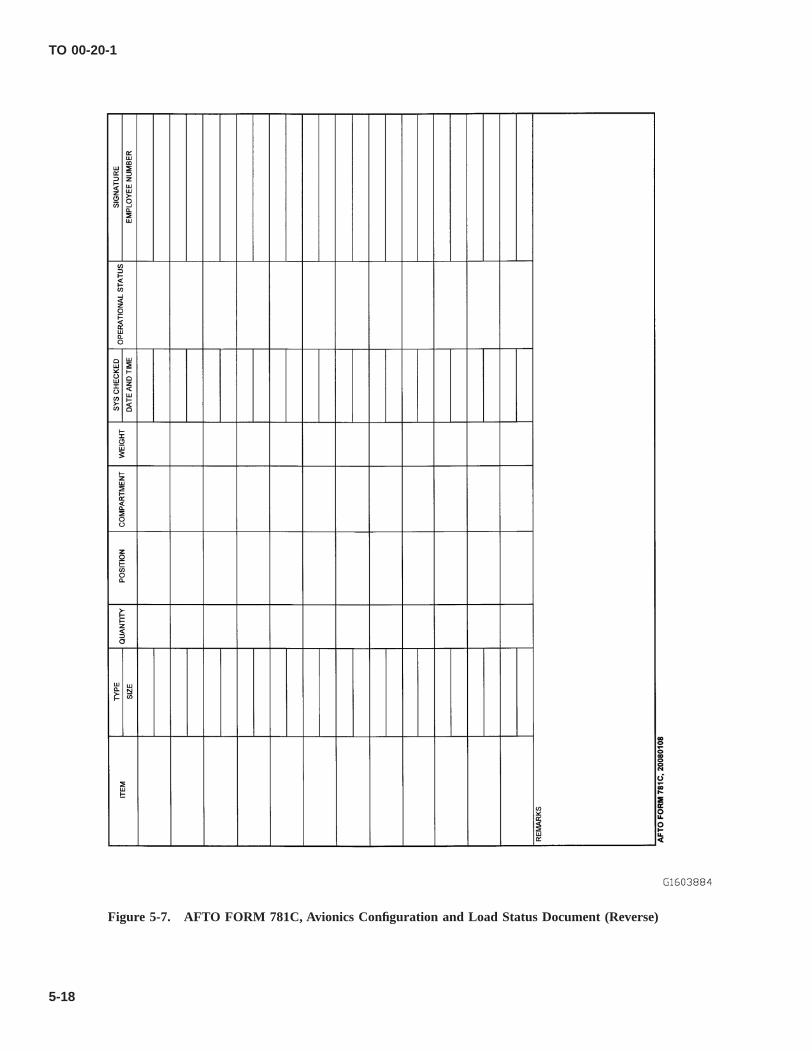
Figure 5-7. AFTO FORM 781C, Avionics Configuration and Load Status Document (Reverse)
TO 00-20-1
5-18

5.10 AFTO FORM 781E, ACCESSORY REPLACEMENT DOCUMENT.
(Figure 5-8 and Figure 5-9). This form is used to record data to facilitate compliance with replacement requirements and thenecessary data for reporting discrepancies when an MIS product is not used. Also use this form to document replacementintervals of the items as specified in the applicable MDS specific -6 TO and maintenance manual, related commodity seriesTOs and accessories and components of reciprocating and turbojet engines as outlined in TO 2J-1-24.
5.10.1 AFTO Form 781E Documentation Instructions. Regardless of whether the equipment is serviceable or repair-able, keep the AFTO Form 781E current as long as the aerospace vehicle or equipment is in the possession of the owningactivity. On aerospace vehicles that have engine events history recording devices installed, compute the elapsed operatingtime as indicated on the recording device and document it on the AFTO Form 781E.
5.10.1.1 Initiate one AFTO Form 781E for aerospace vehicle accessories, and one for each engine. List the replacementitems in the sequence they appear in the applicable MDS specific -6 TO and maintenance manual. Separate these listings intoconvenient groups. Lines may be left blank after each group to provide space for recording replacement of items listedwithin that group.
5.10.1.2 Accessory replacement documents for jet engines (excluding J-79) will include an entry for each main shaftbearing to reflect serial number, manufacturer, part number, location, previous operating time, and the engine time atinstallation.
5.10.1.3 Use a two-line entry for those items requiring replacement at either the aerospace vehicle or equipment time, orspecified cycles, rounds or a calendar period. Use one line to indicate the aerospace vehicle or equipment time and the nextto indicate cycles, rounds or calendar time, at which the replacement is due. Use ditto marks in columns A, B, and C for thesecond line of such entries.
5.10.1.4 Enter additional items requiring replacement, following the listing obtained from the -6 TO and maintenancemanual, that may be required due to the type mission, GEO-LOC, or at the direction of the MXG/CC. When replacementsare made, use the next open line to record entries for the newly installed item.
5.10.1.5 Make a separate entry on the AFTO Form 781E to reflect complete identification data for each explosive itemutilized, such as those employed in aircrew escape systems and external stores jettison systems. Record the followingminimum data; the item nomenclature, type, and item serial number. To complete the identification data, make entries in theLOCATION, REPLACE EVERY, and INSTALLED AT columns. When subsequent changes of these items are made, makeentries in the remaining applicable columns of the form in accordance with the instructions in this section and post new datafor the replacement item.
5.10.1.6 Data for small items, such as a blasting cap, fire extinguisher cartridges or squibs, and squib and plate assemblies,are available only on the outer containers. If an explosive device is received as a component of an assembly and theidentification data are not attached and the shipping organization cannot furnish the data, the date of manufacture stamped onthe item will be used in lieu of the lot number for recording purposes. If the date of inspection is not known, consider theDate of Manufacture (DOM) as the Date of Installation (DOI).
5.10.1.7 Entries on the AFTO Form 781E are as follows:
a. FROM: Enter the date the form was initiated. Example: 20020914.
b. TO: Enter the date the form was closed out and removed from the binder.
c. MDS: Enter the aerospace vehicle’s type MDS. When an AFTO Form 781E is used to track engine mounted accesso-ries, enter the engine type in the MDS block.
d. SERIAL NUMBER: Enter the serial number of the affected aerospace vehicle or engine.
e. PAGE: When more than one sheet of this form is required, enter the page number and total number of pages.
f. Column A, NOMENCLATURE AND TYPE: Enter the nomenclature and type of accessory or equipment requiringreplacement at a specified interval.
TO 00-20-1
5-19

g. Column B, SERIAL NO.: Enter the serial number, normally found on the data plate. If the serial number is not on theaccessory, enter “none.” When new forms are being prepared to replace lost forms and the serial number cannot beidentified without expenditure of excessive man-hours, enter the word “unknown.”
h. Column C, LOCATION: Enter the installed location of the accessory. Leave this block blank when a single installationof the accessory in the aerospace vehicle or engine is involved and the location of the item is obvious.
i. Column D, REPLACE EVERY: Enter the operating interval or the calendar period at which the accessory or compo-nent should be replaced. This replacement time will be found in the applicable MDS specific -6 TO and maintenancemanual or related commodity series TOs. When the replacement intervals for items are reduced locally, enclose theentry in this block within parentheses. Also enclose within parenthesis items prescribed by the MXG/CC. Use of theparentheses denotes unique replacement intervals.
j. Column E, PREVIOUS OPERATING TIME: Enter the previous operating time or usage of the accessory.
k. Column F, INSTALLED AT: Enter the aerospace vehicle or engine time to the nearest hour, or the calendar date, foritems that are changed on an hourly or calendar basis.
l. Column G, REPLACEMENT DUE AT: Enter the aerospace vehicle or engine time to the nearest hour, calendar date,cycles or rounds fired when an accessory or item of equipment is due for replacement. This entry will be the maximumallowable operating time of the accessory. For hourly time change items, add the time to the aerospace vehicle orengine hours entered in column F. When an accessory that has not been overhauled prior to installation is being reused,subtract the previous operating time from the maximum allowable operating time.
m. Column H, REMOVED: Enter the aerospace vehicle or engine time to the nearest hour, cycles, rounds fired orcalendar date at which the accessory or item of equipment was removed. For components requiring replacement basedon actual operating time, such as APUs, entries in columns F, G, and H will be in terms of component operating timeinstead of aerospace vehicle time. Maintain forms for engine mounted accessories in terms of engine operating time.
n. Column I, TIME ACCUMULATED: Enter the accumulated time, cycles or rounds fired on the accessory during thisinstallation period. Compute this by subtracting the installation time, cycles or rounds from the removal time, cycles orrounds.
o. Column J, TOTAL OPERATING TIME: Enter the time, cycles or rounds the accessory was operated since new or lastoverhaul. Compute this by adding the accumulated time entry of column I to the previous operating time entry incolumn E. For example, if an item having 250 hours previous operating time is installed at 550 hours and removed at1050 hours, the operating time will be 750 hours (column J). Entries for items having only a calendar replacementinterval will reflect the calendar period of installation as computed from the date of installation to the date of removal.
TO 00-20-1
5-20

Figure 5-8. AFTO FORM 781E, Accessory Replacement Document
TO 00-20-1
5-21

Figure 5-9. AFTO FORM 781E, Accessory Replacement Document
TO 00-20-1
5-22

5.11 AFTO FORM 781F, AEROSPACE VEHICLE IDENTIFICATION DOCUMENT.
(Figure 5-10 ).
5.11.1 AFTO Form 781F Documentation Instructions. A completed AFTO Form 781F is always displayed at the frontof the AFTO Form 781 series forms binder. When an aerospace vehicle is transferred, revise the data and complete a newform. When possession of the aircraft changes from one organization to another, maintenance supervision will ensure thatthe appropriate data blocks on the form are changed to ensure proper billing of customer’s fuel, maintenance cost per flyinghour, and consumption factors.
5.11.1.1 Fill out the AFTO Form 781F to reflect the requirements of the aerospace vehicle. For a trainer, include all butthe MDS and SERIAL NUMBER block.
5.11.1.2 Post entries on the AFTO Form 781F in bold print in the appropriate blocks in accordance with the followinginstructions:
a. Block 1, CREW CHIEF: Enter the name and grade of the aerospace vehicle dedicated crew chief.
b. Block 2, ASST CC: Enter the name(s) and grade(s) of the assistant aerospace vehicle crew chief(s).
c. Block 3, Blank: Use of this block is GP/CC option.
d. Block 4, DOD ACTIVITY ADDRESS CODE: Enter the DoD activity address code of the base fuels accounts (FP) atthe possessing base (contact Logistics Readiness Squadron (LRS) customer service for the appropriate DoDAC).
e. Block 5, CUSTOMER ID CODE: Enter the customer ID code, using the two-digit Command Code from TO 00-20-2,Appendix B.
f. Blocks 6, MISSION DESIGN SERIES: Enter the aerospace vehicle MDS. Example: C-17A (For ATDs see Paragraph5.2.1.1).
g. Block 7, SERIAL NUMBER: Enter the aerospace vehicle serial number. Example: 85-1428 or 65-14828.
h. Block 8, ORGANIZATION: Enter the designation of the organization to which the aerospace vehicle is assigned.Example: 437 AW.
i. Block 9, LOCATION: Enter the location of the organization to which the aerospace vehicle is assigned. Example:Charleston AFB, SC. Overseas organizations enter their Army Post Office/Fleet Post Office (APO/FPO) number in thisblock.
j. Block 10, STATION CODE: Enter the assigned station code.
5.12 AFTO FORM 781G, GENERAL MISSION CLASSIFICATION-MISSION SYMBOLS.
(Figure 5-11 and Figure 5-12). The AFTO Form 781G contains basic information to serve as an aid in making entries on theAFTO Form 781. If used, file in the rear of the binder.
TO 00-20-1
5-23
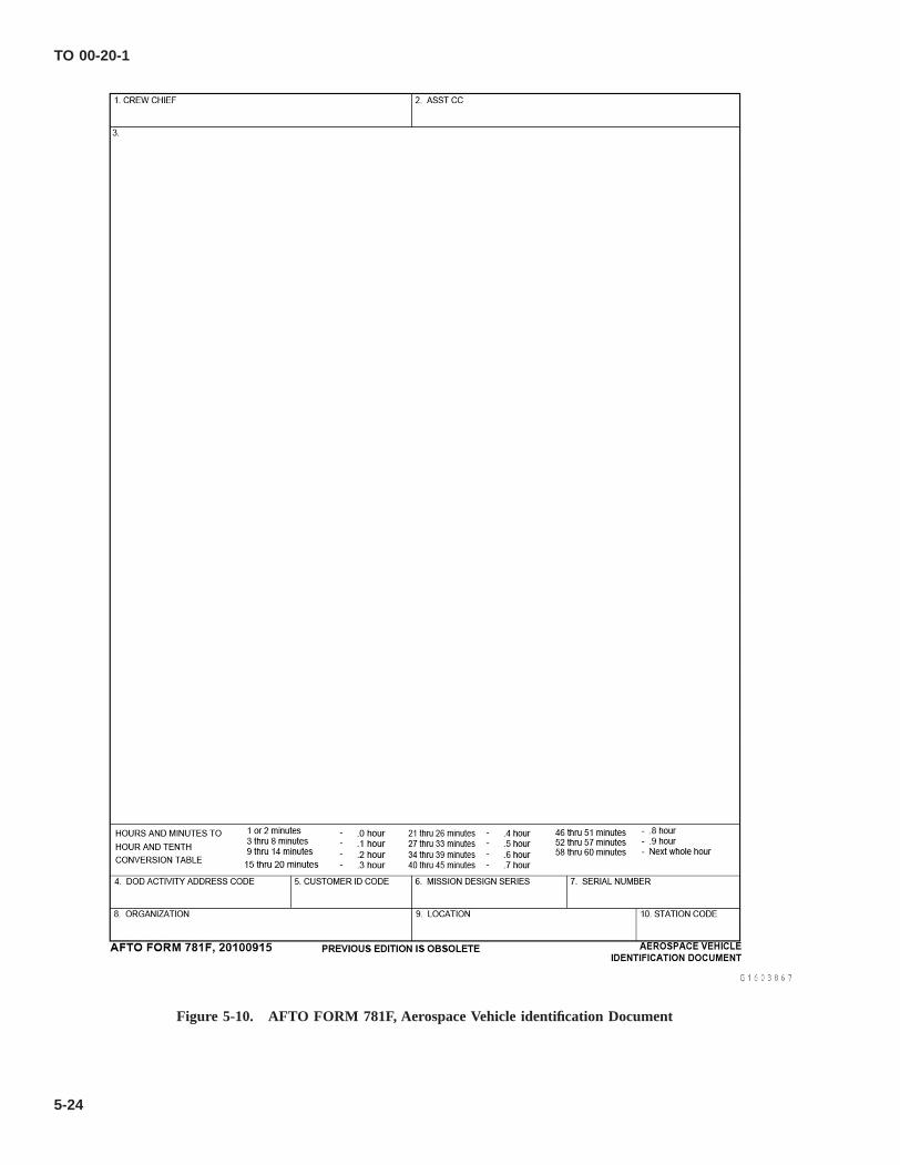
Figure 5-10. AFTO FORM 781F, Aerospace Vehicle identification Document
TO 00-20-1
5-24

Figure 5-11. AFTO FORM 781G, General Mission Classifications-Mission Symbols
TO 00-20-1
5-25

Figure 5-12. AFTO FORM 781G, General Mission Classifications-Mission (Reverse)
TO 00-20-1
5-26

5.13 AFTO FORM 781H, AEROSPACE VEHICLE FLIGHT STATUS AND MAINTENANCE DOCUMENT.
(Figure 5-13 and Figure 5-14). Use the AFTO Form 781H to document maintenance status, servicing information, and toprovide a ready reference as to the status of aerospace vehicles or ATDs. This form also indicates the status and history ofinspections. When off- station, leave the form in the binder until the aerospace vehicle returns to home station. The currentactive AFTO Form 781H will be on top of the old AFTO Form 781Hs.
5.13.1 AFTO Form 781H Documentation Instructions. Prepare a new AFTO Form 781H when the form is full. Ifadditional lines are needed during the specified flying period, initiate a second 781H. Print “Page 1 of 2” at the top of page1, and “Page 2 of 2” on the top of page 2.
5.13.1.1 The aircrew will check the servicing entries recorded in block 11 SERVICING DATA, to verify that the quanti-ties are adequate for the flight. Specific responsibilities are as follows:
5.13.1.1.1 The aircrew documents the airframe time, full stop landings, total landings, landing gear cycles, cartridge/JFSstarts, and engine cycles, as required, in blocks 7, 8, 9 and 10 of the AFTO Form 781H, at the completion of each sortie. Ifan automated flight data recording system is available, maintenance personnel will extract this information from the debriefin accordance with MDS specific guidance and enter onto the AFTO Form 781H blocks 7, 8, 9 and 10 at the completion ofeach sortie as part of the debrief process.
5.13.1.2 AFTO Form 781H Entries. Complete the form for aerospace vehicle and ATDs in the following manner:
5.13.1.2.1 For ATDs, completion of blocks 1 through 4 and 6 STATUS TODAY is mandatory and completion of theexceptional release portion of block 6 and the remaining blocks is a GP/CC option.
5.13.1.2.2 Block 1, FROM: Enter the year, month, and day of the beginning date for the use of this form, in the followingformat: YYYYMMDD.
5.13.1.2.3 Block 2, TO: Enter the ending date for the use of this form.
5.13.1.2.4 Block 3, MDS: Enter the aerospace vehicle MDS. Example: C-130H.
5.13.1.2.5 Block 4, SERIAL NUMBER: Enter the aerospace vehicle serial number. Example: 85-1500 or 65-0966.
5.13.1.2.6 Block 5, Certification of PR, PR/BPO, TH, BPO, QT, ICT, WAI, PLI: The maintenance person who accom-plishes or supervises the above listed actions will enter in the appropriate columns; the type inspection, minimum signatureand the local date and time completed. MAJCOMs have the option of using Zulu time. When initiating a new form, transferthe time and date of the current PR inspection (provided the validity period has not expired) and the most current TH (ifapplicable), and carry forward the individual’s minimum signature who accomplished the inspections by printing in block 5of the new form. The individual transcribing the entries enters the abbreviations “CF” under the TYPE column and their firstand last name initial in the ACCOMPLISHED BY column of the old form. Record the entries for each column of this blockas follows:
a. TYPE: Enter the abbreviation of the type inspection.
b. ACCOMPLISHED BY: Use this column to record the minimum signature of the individual who accomplished theinspection.
c. COMPLETED DATE/TIME: Enter the date in YYYYMMDD format, and time of completion.
5.13.1.2.7 Block 6, STATUS DATA: Entries will be:
5.13.1.2.7.1 STATUS TODAY: Enter symbols in the STATUS TODAY column to reflect current status of the aerospacevehicle. A black last name initial indicates no known discrepancies which require a symbol exist; and no inspections are dueor overdue on the aerospace vehicle. When initiating this form, bring forward the last status symbol of the previous form tobox 1 of the new form. If no discrepancies exist on the aerospace vehicle, enter the last name initial of the authorizedindividual who accomplished or supervised the pre-flight inspection. The status symbol recorded in these columns always
TO 00-20-1
5-27

represents the most serious condition. When status changes occur, the maintenance technician responsible for the change willuse the next open box to record the applicable symbol. Symbol entries recorded in these columns will never be erased orinitialed over. If a symbol is entered in error, enter the correct symbol in the next open box.
5.13.1.2.7.2 BOX NO: This column is used to record the box number of the STATUS TODAY column for which anexceptional/conditional release is being signed. This entry is the responsibility of the authorized individual who signs theexceptional release.
5.13.1.2.7.3 EXCEPTIONAL RELEASE: An exceptional release is required before flight. Under no circumstances willthe exceptional release be granted when the aerospace vehicle status is indicated by a Red X symbol. The exceptional releaseserves as a certification that the authorized individual who enters their minimum signature has reviewed the active forms toensure the aerospace vehicle is safe for flight.
5.13.1.2.7.3.1 A list of personnel designated to sign the exceptional release will be approved by the GP/CC. Thesepersonnel must be an aircraft maintenance officer, SNCO or their civilian equivalen. If, after thorough review, the GP/CCdetermines that local conditions require the assignment of other than maintenance officers, SNCOs or their civilian equiva-lents to sign exceptional releases, a waiver request is forwarded to the MAJCOM for approval. Such request must fullyjustify the need for the waiver and identify actions being taken or planned to resolve the problem.
5.13.1.2.7.3.2 When an exceptional release is signed by a designated individual, it will not require another signatureduring the pre-flight validity period unless additional Red symbol discrepancies are encountered or the AFTO Form 781Hhas to be removed as outlined in Paragraph 5.13.1. When an additional symbol is entered or the form is removed, the priorsignature is no longer valid and another exceptional release is necessary. When designated personnel are not available to signthe exceptional release, the Aircraft Commander will sign the release. When a release is signed by the Aircraft Commander,it is effective only for those flights in which the releasing Aircraft Commander participates as an aircrew member. Thelaunch control officer, maintenance officer, SNCO or civilian equivalent will sign an exceptional release, when required forinstalled air launched missiles. For aerospace vehicle (including bailed and government furnished property) undergoingmaintenance at a contractor’s facility, exceptional releases shall be signed by personnel identified by the contractor in alisting provided to the Air Force Contract Administration Office, as required by this TO. Additional special instructionsrelative to exceptional releases are as follows:
5.13.1.2.7.3.3 If in Transient status and the aircrew desires omission of an inspection even though the required resourcesare available, the aircrew will make an entry on the AFTO Form 781A stating the reason for their decision. The aircrew willsign the exceptional release. A duplicate of the AFTO Forms 781A and 781H will be made, and will be retained by theTransient Alert (TA) supervisor for not less than 90 days and disposed of in accordance with AFMAN 33-363.
5.13.1.2.7.3.4 If TA cannot accomplish the required inspections, servicing or repairs because of a lack of qualifiedpersonnel, facilities or material, and the A/C does not wish to continue the flight without accomplishment of these items, theA/C will contact the home station of the aerospace vehicle to request assistance. If the A/C elects to proceed on the flightwithout accomplishment of these items, document the AFTO FORM 781A, including a brief entry describing the situation.The A/C will sign the exceptional release. A duplicate of the AFTO Forms 781A and 781H will be made, and will beretained by the TA supervisor for not less than 90 days and disposed of in accordance with AFMAN 33-363.
5.13.1.2.7.3.5 An exceptional release may be granted as a conditional release. A conditional release allows an aerospacevehicle to be flown although a discrepancy exists which restricts the aerospace vehicle’s capabilities. When such conditionalreleases are granted, the conditions of the release will be described by an appropriate entry in the AFTO Form 781A.Additionally, enter “conditional, see AFTO Form 781A, (page ____, and item ____)” in the next open line after theexceptional release signature. As an example, conditional releases may be given to an aerospace vehicle that has cargoweight restrictions due to cracks, fuel limitations or airspeed restrictions, etc.
5.13.1.2.7.3.6 To indicate what conditions are covered by the exceptional release, the releaser will draw a red line underthe entire last entry on the AFTO Form 781A. When the exceptional release is signed, the releaser places their initials at theleft margin of the AFTO Form 781A beside the red line entry. If new discrepancies are entered, draw a new red line underthe last item to indicate coverage of the next exceptional release signature. If the same person who signed the previousexceptional release reviews the discrepancies and corrective actions, the individual may initial beside the red line and releasethe aerospace vehicle without another minimum signature in block 6, provided the status has not changed. If no additionalred symbol entries are entered, but the aerospace vehicle status changes to a Red Dash or Red Diagonal as a result of anAFTO Form 781K entry, a new exceptional release is required. The releaser will initial immediately above the originalinitials on the AFTO Form 781A.
TO 00-20-1
5-28

5.13.1.2.8 Block 7, AIRFRAME TIME: Upon initiation of a new form, transcribe the total time from the TOTAL block ofthe previous form to the PREVIOUS block of the new form. Ensure the airframe time is updated in the AFTO Form 781J.At the completion of each flight, record the flight time pertaining to the date involved in the appropriate flight blocks.Aircraft with automated flight data recording systems will utilize the data provided by the automated flight data recordingsystem. Add these entries for a new total entry in the block at the end of the specified flying period.
5.13.1.2.9 Block 8, LANDINGS: Use this block to record previous FULL STOP, TOTAL, and LANDING GEARCYCLES on aerospace vehicles for which maintenance or inspection of the landing gear system or components is based ona specified number of landings/gear cycles. Maintain a separate record of full stop landings for aerospace vehicles under thiscriteria. The aircrew will document total landings, which include full stop landings, in the TOTAL column and documentonly the full stop landings in the FULL STOP column. These entries will be added for a new total entry in the TOTAL blockat the end of the specified flying period. If applicable, aircrew will also document LANDING GEAR CYCLES (gear fullup/full down). Aircraft with automated flight data recording systems, will utilize the data provided and stored by theautomated flight data recording systems in accordance with MDS specific guidance.
5.13.1.2.10 Block 9, CART/JFS STARTS: For aircraft/engines with cartridge/JFS start capability, maintain a history ofcartridge/JFS starts to determine starter time change. The aircrew will document in the CART/JFS START column by enginenumber, the number of cartridge/JFS starts for each flight. Maintenance personnel will document each ground cartridge/JFSstart. These entries will be added for a new total in the TOTAL block at the end of the specified flying period. This total willbe carried forward to block 9, PREVIOUS of the new AFTO Form 781H.
5.13.1.2.11 Block 10, ENGINE CYCLE DOCUMENTATION: For selected engines listed in TO 00-25-254-1, maintain ahistory of cycles for compressors, turbine disks, and other designated components to determine fatigue life. The aircrew willdocument cycles which have occurred during the flight, on the FLIGHTS line. The definition of cycles for each engine isincluded in the applicable aerospace vehicles MDS specific -1, -2, and -6 TOs and the appropriate engine TO and mainte-nance manual. Aircraft with automated flight data recording systems, will utilize the data provided and stored by theautomated flight data recording systems.
NOTE
When blocks 8, 9, 10, 11 and 12 are not used line out the printed words and use the blocks for other purposes asapproved by the GP/CC.
5.13.1.2.12 Block 11, SERVICING DATA: Servicing data is grouped into four basic categories: FUEL, OIL, OXYGENAND NITROGEN/WATER. A dash in servicing rows will indicate that in-tank checks have not been complied with or arenot required. For example, if only fuel is checked or serviced, put a dash in the servicing rows for OIL, OXY, andNITROGEN/WATER blocks and carry down previous in-tanks totals. Specific entries are as follows:
5.13.1.2.12.1 OCTANE or GRADE: For each servicing line, enter the fuel grade/octane with which the aerospace vehiclewas serviced. Example: JP-8.
5.13.1.2.12.2 QTY SRVCD: Enter the total quantity of fuel (Pounds, Gallons or Liters) serviced or drained at oneoperation. If no service is required, enter a “0” (zero) to serve as a positive indication that the tanks have been checked. Toindicate the unit of measure being used for the QTY SRVCD and TOTAL IN TANKS entries, enter “P,” “G,” or “L,” whichwill indicate pounds, gallons or liters, as a part of the serviced or in tanks entry. Example: 2,750P or 6,243G. Enter totalpounds, gallons or liters of fuel drained in red and carry a minus sign prefix. Example: -250G. Record fuel taken onboard,fuel dumped overboard, fuel off loaded or oil transferred from an auxiliary tank to an engine or engines during flight, as aseparate service in the next open row. Enter the quantity of fuel dumped or off loaded in red and carry a minus sign prefix.The aircrew or other aircrew member will make these entries for in-flight operations.
5.13.1.2.12.3 TOTAL IN TANKS: Upon completion of servicing, draining or completion of an in-tank check, enter thetotal number of pounds (P), gallons (G) or liters (L), of fuel onboard in all tanks (excluding in-flight refueling tanks of tankeraerospace vehicles). Enter a separate line entry when a different grade of fuel is onboard other than that of the aerospacevehicles.
5.13.1.2.12.4 OIL (Half pints, pints, quarts, gallons or liters): Line out the non-applicable words from the title of thiscolumn to indicate what units of measure are being used and list the type and/or specification of the oil serviced to the rightof the title, if different than what the TO calls for. In the SER column of the applicable servicing number row, enter thenumber of half-pints, pints, quarts, gallons or liters of oil serviced or drained from each oil tank. Record the total number ofhalf-pints, pints, quarts, gallons or liters of oil in each engine tank after servicing or draining in the IN column. If no in-tanks
TO 00-20-1
5-29

checks are performed, then enter a dash in the SER column and carry down previous IN totals. If no servicing is required,enter a “0” (zero) in the SER column to serve as a positive indication that the in-tanks checks have been made. Enter oildrained in Red and a minus sign prefix. Example: -15. To indicate a complete oil change, circle amount added in SERcolumn in Red. If different oils are mixed according to TO 42B2-1-1, make an appropriate entry in the AFTO Form 781A.Aerospace vehicles having requirements for recording constant speed drive (CSD) and extended range oil tank (ext. range)oil servicing, will draw a red line between columns after the last engine entry and record CSD or EXT oil servicinginformation behind the red line separator. Cross out the engine number of the column being used and enter the CSD or EXTnumber. Example: CSD # or EXT range #.
5.13.1.2.12.5 OXY PRESS OR QTY: Line out the non-applicable portion of the title. In the OXY PRESS OR QTYcolumn of the applicable servicing number row, enter the oxygen system pressure or quantity serviced. The individualmaking the check will ensure the pressure or quantity is at or above the minimum prescribed in the applicable -2 TO. If noquantity check is required, enter a dash. Leave this block blank for aerospace vehicles not equipped with oxygen.
5.13.1.2.12.6 NITROGEN/WATER: In the nitrogen/water servicing column, enter the nitrogen/water quantity. If thiscolumn is not used, the GP/CC may designate its use for other purposes. For example, F-16 units may use this column todocument hydrazine (H-70) quantity.
5.13.1.2.12.7 PRE TOT: When transcribing the AFTO Form 781H, this row is used to record the current FUEL, OIL,OXY, etc. totals from the previous AFTO Form 781H, block 11, last applicable servicing number row. To ensure noadditional entries are made on the PRE TOT row, line through all servicing blocks.
5.13.1.2.13 Block 12, SERVICING CERTIFICATION: The individual who performs or supervises the servicing, drainingor in-tanks check of items in block 11, enters their minimum signature in the BY block corresponding with the numberedservicing row recorded in block 11. Unless classified, enter the station name and date at which the action was performed inthe corresponding AT and DATE blocks. The aircrew or other aircrew member will sign the BY block, enter the words“in-flight” or “hot pit” in the AT block and the date in the DATE block to certify any in-flight or hot pit servicingaccomplished.
TO 00-20-1
5-30

Figure 5-13. AFTO FORM 781H, Aerospace Vehicle Flight Status and Maintenance Document
TO 00-20-1
5-31

Figure 5-14. AFTO FORM 781H, Aerospace Vehicle Flight Status and Maintenance Document (Reverse)
TO 00-20-1
5-32

5.14 AFTO FORM 781J, AEROSPACE VEHICLE ENGINE FLIGHT DOCUMENT.
(Figure 5-15 and Figure 5-16).
5.14.1 AFTO Form 781J Documentation Instructions.
NOTE
For engines equipped with Engine Monitoring Systems (EMS) such as F100, F110, TF34, T701C, etc. use of theAFTO Form 781J is by the direction of the GP/CC. For those engines not incorporating EMS tracking like T56,TF33, etc. use of the AFTO Form 781J is required.
5.14.1.1 FROM and TO: Enter the date on which the form was initiated in the FROM block. When the form is closed out,enter the date in the TO block. The FROM block on the new form will agree with the TO block on the old form.
5.14.1.2 MDS: Enter the aerospace vehicle MDS . Example: C-130H.
5.14.1.3 SERIAL NUMBER: Enter the aerospace vehicle serial number. Example: 85-1428 or 65-14828.
5.14.1.4 PAGE___ OF___PAGES: Enter the page number and the total number of pages.
5.14.1.5 AIRCRAFT AND ENGINE OPERATING TIME, CYCLE AND OIL ADDED: Line through non-applicablemeasurements in the header (Half Pints, Pints, Quarts).
5.14.1.6 DATE: Enter the date on which the aerospace vehicle flies in the first open line.
5.14.1.7 AIRFRAME TIME: When transcribing the AFTO Form 781J, the PREVIOUS TOTAL row is used to record thelast entry of data documented on the previous AFTO Form 781J CARRIED FWD row. The last entry in this columncorresponds with the TOTAL row entry in block 7 of the AFTO Form 781H. At the end of the specified flying period, enterthe time accrued for that flying period on the line opposite the specific date entry. Add this entry to the previously recordedtime to provide new totals. GP/CCs may elect to post entries on this form for each flight in lieu of the specified flying period.
5.14.1.8 OIL SAMPLE (X): Enter an X in this block, on the line corresponding to the specific date entry to indicate thatan oil sample was taken for oil analysis. This distinguishes the correct placement of the X, (line entry vs total).
5.14.1.9 OIL ADDED: In the OIL ADDED column of the PREVIOUS TOTAL row, enter the total amounts of oil addedin Half Pints (HP), Pints (P) or Quarts (Q), as reflected on the last entry of the previous AFTO Form 781J.
5.14.1.9.1 Enter the total amount of oil serviced for each engine on the line corresponding to the specific date entry. TheGP/CC may elect to post entries after each flight. The amount of oil serviced for each engine will match oil servicingamounts reflected in the AFTO Form 781H, block 11, SERVICING DATA. Add these oil amounts to the previously recordedOIL ADDED column amounts to derive new cumulative totals. Use this column to maintain precise, cumulative totals of oiladded for each engine to facilitate accurate documentation on DD Form 2026, OIL ADDED SINCE LAST SAMPLE block.Accurate running totals of oil added to each engine between oil samples are essential for performing accurate oil analysisand preventing potentially catastrophic engine/component failures. Ensure amounts of oil serviced for each engine are alsoannotated on the AFTO Form 781H.
5.14.1.9.2 For engine programs that do not require oil samples to be taken or do not use DD Form 2026, there is norequirement to record amounts of oil serviced on the AFTO Form 781J.
5.14.1.10 OIL CONSUMPTION: Optional Column. If used, enter the oil consumption rate (Qts/Hr) after each flightcompletion and calculate the oil consumption total after obtaining individual engine flight consumption rates. The oilconsumption rate is obtained by dividing the oil added amount by the flight time, while the rolling total is obtained bydividing the total oil added by the total airframe time.
5.14.1.11 ENGINE POS #: The first engine ENGINE POS # column is for engine number 1, the second is for enginenumber 2 and so on. One- and two-engine aerospace vehicles may use the remaining engine position columns as continua-tions. If a column is not used, GP/CCs may authorize other standardized entries (e.g. engine start cycles, events, times,
TO 00-20-1
5-33

attempts, daily/flight information, etc.). For aerospace vehicles with more than four engines, use front and back, or use asecond form if single sided, to track additional engines. Label each column with the appropriate engine position numbers andeach form with appropriate headings.
5.14.1.12 OIL CHANGE/TIME: Enter the engine time at the last oil change. To facilitate completion of DD Form 2026,circle the engine operating time in red when an oil change is made.
5.14.1.13 ENGINE TIME and CYCLES: Engine time will reflect engine total hours accumulated throughout the life ofthe engine. Therefore, the accrued CYCLES column will start with the accumulated cycles annotated on the AFTO Form 95prepared by the overhaul activity and will be found immediately after the Total Time (TT) and Time Since CompleteOverhaul (TSCO). This information will be used for the initial cycles entry on the new AFTO Form 781J. If previouslyaccumulated cycles are not available, contact the applicable ALC engine manager.
5.14.1.13.1 On aerospace vehicles that have engine-recording devices installed, the engine time need not be entered in theENGINE TIME columns. Line out the ENGINE TIME in the ENGINE POS #1 block and in as many other number engineblocks as required, and enter the Event History Recorder (EHR) ″Ser. No.″ or Engine Time Temperature Recorder (ETTR)″Ser. No.″ as applicable.
5.14.1.13.2 When an engine change occurs, post a brief entry in the next open date line. Reopen entries for the newengine, together with active entries of other columns in the TOTAL row. Transcribe total cycles/hours accumulated on theremoved engine to the engine AFTO Form 95. Extract accumulated cycles on the newly installed engine from the AFTOForm 95.
5.14.1.14 CARRIED FWD: When all rows have been completely filled in or when rows have been utilized to the extentthat initiation of a new 781J becomes necessary; total all columns in the appropriate blocks in the CARRIED FWD row.Carry these individual totals along with other applicable data forward to the appropriate blocks of the new AFTO Form 781J.
5.14.1.15 When corrections are made to the airframe and engine operating time and cycle documentation data, enter themin red to highlight the changes.
5.14.1.16 For jet engine powered missiles, use the AFTO Form 781J to document the missile airframe time and engineoperating time. Missile airframe time will be the same as each day’s flight time of the carrier aerospace vehicles. The totalmissile airframe time will be cumulative for the life of the missile. Engine operating time will be cumulative for the installedengine and the document will be appropriately adjusted when an engine change occurs. When missile forms are carriedaboard the aerospace vehicle, the aircrew will ensure the time entries are made.
TO 00-20-1
5-34

Figure 5-15. AFTO FORM 781J, Aerospace Vehicle Engine Flight Document
TO 00-20-1
5-35

Figure 5-16. AFTO FORM 781J, Aerospace Vehicle Engine Flight Document (Reverse)
TO 00-20-1
5-36

5.15 AFTO FORM 781K, AEROSPACE VEHICLE INSPECTION, ENGINE DATA, CALENDAR INSPECTION,AND DELAYED DISCREPANCY DOCUMENT.
(Figure 5-17 and Figure 5-18)
5.15.1 AFTO Form 781K Documentation Instructions. Enter the appropriate heading entries (Date(From/To), MDS,and Serial Number) at the top of the form in accordance with the instructions that apply to the AFTO Form 781H (Paragraph5.13.1.2).
5.15.1.1 The GP/CC may approve use of a separate AFTO Form 781K for each aerospace vehicle engine. This form willbe maintained in the aerospace vehicle forms binder. Standardize entries among like engines. The AFTO Form 781K(s) willstay with the engine upon removal. File these engine AFTO Form 781K(s) directly following the aerospace vehicle AFTOForm 781K.
5.15.1.2 Block A, AEROSPACE INSPECTION STATUS: Use the boxes to the right of the title NEXT PERIODIC,MAJOR OR PHASED INSPECTION DUE NO. to document the number and type of the next inspection due. Use theTYPE, COMPL, and NEXT DUE columns to identify the types of inspections involved, including Home Station Check(HSC) and Hourly Post-flight (HPO), the airframe time or date an inspection was completed; and the airframe time or datean inspection is next due. Upon completion of the prescribed inspection listed in this block, line out the old COMPL and theNEXT DUE entries and enter the new COMPL and NEXT DUE time.
5.15.1.3 Block B, ENGINE DATA: This block is provided to record engine position, serial number, and engine changedue time. In the ENG SER NO, enter the serial number of each engine in the box to the right of the applicable number thatdenotes the position in which each engine is installed. In the ENG CHANGE DUE TIME column, enter the aerospacevehicle/engine time at which the next engine change is due. Transcribe only current engine entries when initiating a newform. This block may be left blank for ATDs and for aerospace vehicles which have engine history recording devicesinstalled. For aerospace vehicles with modular engines, the time change due date will be based on the lowest time remainingmodule. Aerospace vehicles with Engine History Recorders (EHR) will enter EHR serial numbers under the engine changedue time.
5.15.1.4 Block C, CALENDAR AND HOURLY INSPECTION SCHEDULE: Use this block to document inspectionitems that are to be inspected or tested at a specific hourly or calendar period. List calendar and hourly inspections withfrequency and next due date. Items listed will be primarily those short-term special inspection requirements that frequentlybecome due. Short-term items are those having an interval of less than six months or an hourly interval less than the periodicinspection interval. After completion of inspection, line out the date or hourly inspection that was due. In the NEXT DUEdate block, annotate when the next inspection, calendar or hourly, is due. When an inspection is overdue, an AFTO Form781A entry will be annotated with appropriate Red symbol. For control purposes, load all installed aircrew flight equipmentitems in the MIS.
5.15.1.5 Block D, DELAYED DISCREPANCIES, URGENT ACTION, AND OUTSTANDING ROUTINE ACTIONTCTOs: Enter all delayed discrepancies, urgent action TCTOs, Category I routine action safety modification TCTOs, out-standing routine action TCTOs or commercial equivalents in this block. Delayed discrepancies may be transferred from theAFTO Form 781A, or upon completion of scheduled maintenance from the MIS-generated discrepancy form or WCD.Transfer urgent action and Category I routine safety TCTOs from the AFTO Form 781K to the AFTO Form 781A uponnotification of applicability in anticipation of immediate accomplishment. List open TCTOs grounding within 120 days andany part/component in overfly. When compliance with routine action Category I TCTOs or commercial equivalents forwhich kits or parts are available depends upon prior compliance with depot TCTOs, time computation for application of theRed Diagonal does not begin until the depot work is accomplished. After the depot work is accomplished, apply the RedDiagonal at the specified number of days in the category I TCTO. For IMDS units, mandatory entries for deferred discrep-ancies are SYM, JOB CONTROL NUMBER, and DOCUMENT NUMBER (if parts are required). Mandatory entries forTCTOs are TCTO NUMBER, and GROUND DATE/TIME (date TCTO grounds).
5.15.1.5.1 Enter symbols in the SYM column of the AFTO Form 781K to reflect the seriousness of the particulardiscrepancy. Some rules concerning symbol entries are:
5.15.1.5.1.1 Never enter a Red X on the AFTO Form 781K; only use Red Diagonal and Red Dash symbols. Once entered,symbols will not be erased or initialed over.
5.15.1.5.1.2 When the symbol for a TCTO or a discrepancy entered on the AFTO Form 781K is to be upgraded, transferthat TCTO or discrepancy to the AFTO Form 781A. Enter the upgraded symbol in the AFTO Form 781A SYM block.
TO 00-20-1
5-37

5.15.1.5.1.3 If a symbol is entered in error, the person making the entry will enter the following statement in theDELAYED DISCREPANCIES OR TCTO NUMBER AND PUBLICATION DATE block: “Symbol entered in error, discrep-ancy and correct symbol reentered below.” The person will enter their employee number or USERID in the TRANSFER BYEMPLOYEE NUMBER block. Then reenter the discrepancy, with the correct symbol, on the next open row.
5.15.1.5.2 The assigned JCN will be entered in the JOB CONTROL NUMBER column.
5.15.1.5.3 Enter the delayed discrepancy narrative or TCTO number date, and short title in the DELAYED DISCREP-ANCIES OR TCTO NUMBER AND PUBLICATION DATE column. When delayed discrepancies are added to this sectionfor reasons other than parts, a brief explanation will follow the discrepancy.
5.15.1.5.4 Enter the supply document number for all delayed discrepancies, if applicable, in the DOCUMENT NUMBERcolumn. For TCTOs, no supply document number (when parts, kits, and tools are required) will be required.
5.15.1.5.5 Enter the TCTO grounding date or airframe time, as applicable, in the GROUND DATE/TIME column.
5.15.1.5.6 When a delayed discrepancy or TCTO entered on the AFTO Form 781K is to be corrected or accomplished, theentry must be transferred to the AFTO Form 781A or WCD. After the entry is transferred to the AFTO Form 781A, followprocedures for clearing AFTO Form 781A entries. When an aerospace vehicle is undergoing a scheduled inspection, transferentries to an MIS-generated discrepancy form, WCD or to the AFTO Form 781A for corrective action or upgrading.
5.15.1.6 When it becomes necessary to initiate a new AFTO Form 781K, carry forward open delayed discrepancies,TCTOs, and other data affecting the status of the aerospace vehicle to the new form. Upon completion of the transfer action,the transcriber will enter their minimum signature in block D.
5.15.1.7 When an entry is transferred, the person accomplishing the transfer will enter their employee number or USERIDfor the entry in the TRANSFERRED BY EMPLOYEE NUMBER column. Line out the transferred entry with a single lineexcept for the employee number block. The line will denote that the entry has been transferred. When a Red Dash symbol isinvolved, draw the line above or below the Red Dash, so it will not hide the symbol. Aerospace vehicles inducted into PDMwill follow procedures specified in Paragraph 8.1.5.1.
TO 00-20-1
5-38

Figure 5-17. AFTO FORM 781K, Aerospace Vehicle Inspection, Engine Data, Calendar Inspection and DelayedDiscrepancy Document
TO 00-20-1
5-39

Figure 5-18. AFTO FORM 781K, Aerospace Vehicle Inspection, Engine Data, Calendar Inspection and DelayedDiscrepancy Document (Reverse)
TO 00-20-1
5-40

5.16 AFTO FORM 781M, STATUS SYMBOLS AND FUNCTIONAL SYSTEM CODES .
(Figure 5-19 and Figure 5-20). The AFTO Form 781M contains basic information to serve as an aid in making entries on theAFTO Forms 781A and 781K. If used, this form is inserted in a clear page holder and placed at the rear of the binder.
5.17 AFTO FORM 781P, SUPPORT GENERAL DOCUMENTATION RECORD.
(Figure 5-21 ). Support General Documentation records are those maintenance actions that are considered routine in the dayto day support of the weapon system operations. Support General includes parking, fueling, cleaning, documentation,unpacking, scheduled and unscheduled inspection, etc.
5.17.1 AFTO Form 781P Process. MAJCOMs have the option of requiring Support General reporting.
5.17.1.1 Use the AFTO Form 781P to record support general actions when an automated system is unavailable. SupportGeneral Codes beginning with 03, 04, and 09 will be reported.
5.18 PAPERLESS PROCESS.
5.18.1 Utilizing Paperless Process. When utilizing the paperless process and AFTO Form 367 (Figure 5-22), locallydeveloped lists or WCDs are not used. All MAJOR (Red X) discrepancies will be entered directly into the MaintenanceInformation System (MIS).
5.18.1.1 If a paperless inspection process is approved by the MXG/CC and utilized, units will develop specific proceduresand publish them in a Base/MXG supplement or instruction. The following minimum guidelines will be met:
5.18.1.1.1 Prior to beginning the paperless process, verify all forms entries are in the MIS and pull the aircraft forms.
5.18.1.1.2 Units will locally develop a cover sheet strictly for the use of forms pulled for the paperless process. At aminimum, the cover sheet will include the following information: aircraft tail number, aircraft forms dates, including fromdate and date inactivated, reason for removal (i.e. paperless inspection), number of pages removed from each type of form(i.e. 781A, 16 pages inactivated), the statement “I verify that all open entries have been entered/validated in IMDS/G081”,printed name and employee number of coordinator/dock chief/team leader, followed by their signature. These permanentlyinactivated forms will be filed in the aircraft jacket file with the inspection package.
5.18.1.1.3 Units will use already published aircraft impoundments procedures when utilizing the paperless process.
5.18.1.1.4 Units may use the AFTO Form 367, or a locally developed/approved gig sheet to document minor discrepan-cies. All MAJOR (Red X) discrepancies will be documented in the MIS. Upon completion of the inspection, gig sheets willbe filed in the aircraft jacket file as part of the inspection package.
5.18.1.1.5 Units will develop procedures that address what to do in the event of an extended MIS or power outage.
5.18.1.1.6 Units will develop procedures that address how they will display informational notes, aircraft warning notesand warning tags. Warning tags will be documented per Paragraph 5.7.1.3.10.5.
TO 00-20-1
5-41

Figure 5-19. AFTO FORM 781M, Status Symbols and Functional System Codes
TO 00-20-1
5-42

Figure 5-20. AFTO FORM 781M, Status Symbols and Functional System Codes (Reverse)
TO 00-20-1
5-43

Figure 5-21. AFTO Form 781P, Support General Documentation
TO 00-20-1
5-44

Figure 5-22. AFTO Form 367, Aircraft Discrepancy Gig Sheet
TO 00-20-1
5-45/(5-46 blank)


CHAPTER 6ACCESSORY REPLACEMENT AND REUSE PROCEDURES
6.1 GENERAL.
6.1.1 Accessory Replacement and Reuse. Accessories, as defined in this TO, include both Time Change Items (TCI)and Condition Replacement Items (CRI). Those accessories not identified in the applicable MDS specific -6 TO and main-tenance manual as TCI are CRI. CRI only require replacement when it is determined they are operationally unserviceable.
6.1.1.1 Do not remove items from aerospace equipment involved in a mishap until investigation personnel authorize suchremovals. Reuse of parts or accessories from wrecked or damaged aerospace equipment requires extreme caution. Beforeconsidering reuse, use the appropriate TOs to conduct thorough testing and/or inspections of items that may have beendamaged. Although the external appearance may indicate that the item was not damaged, hidden flaws may exist due tostress, strain or other forces that can only be detected by testing and inspection. Items routed for test and/or inspection willinclude a notation on the AFTO Form 350 that the item was removed from wrecked or damaged aerospace equipment. In theabsence of appropriate TOs contact the SM through the MAJCOM for guidance.
6.1.1.2 Designation of parts removed from aerospace equipment contaminated with chemical, biological or radiologicalagents will be labeled with the contamination date and type of agent on an AFTO Form 350. Equipment markings willensure all handlers of the contaminated parts are aware of possible residual contamination hazards. Removed parts notrepaired and replaced must be disposed of per AFMAN 10-2503.
6.2 TCI REPLACEMENT.
6.2.1 Replacement Policies. Items designated as TCIs are replaced at specified intervals. The primary objective of thetime-change replacement program is to achieve maximum utilization of components consistent with the economic operationof aerospace equipment without jeopardizing flight or operational safety. Time-change replacement requirements are pre-scribed only for those items that have a measured service life expectancy and that display an age related failure pattern, (e.g.a failures rise sharply at some given operating time or age of an item).
6.2.1.1 TCIs must fall into one or more of the following categories to be a valid candidate for time-change replacement:
6.2.1.1.1 Items whose failure due to location or function within a system would compromise safety of flight of airbornesystems or the operational safety of ground equipment.
6.2.1.1.2 Items whose failure due to location or function within a system would definitely cause a mission to abort orground equipment failures for excessive downtime of mission critical items.
6.2.1.1.3 Items for which a failure might cause damage beyond economical repair.
6.2.1.1.4 Items whose physical characteristics allow an accurate prediction of deterioration from calendar time or hours inoperational use.
6.2.1.2 The replacement schedule in the -6 or inspection workcards are the only authority for the scheduled replacementinterval of accessory and components, except for the following deviations:
6.2.1.2.1 TO 2-1-18, will be used as the authority for scheduled replacement of reciprocating engines, gas turbine engines,and propeller reduction gearboxes.
6.2.1.2.2 The 11P or 11A series TOs will be used for scheduled replacement of explosive devices. Service life require-ments for AFE items can be found in specific TOs, for example 14D, 14S, 15X, etc.
6.2.1.2.3 The MDS specific -6 TOs or inspection workcards will make note of each listed item and reference the appli-cable commodity series TOs. These TOs will serve as authority if in conflict with the MDS specific -6 TOs or workcards.
TO 00-20-1
6-1

6.2.1.3 Replacement intervals for any specific item are based on the aerospace equipment installation and utilization,rather than being a general replacement interval for all applications. Based on this rule, the replacement interval for anidentical item may vary considerably for different aerospace equipment application.
6.2.1.4 Equipment in an operational status used for ground instructional purposes will have the TCIs replaced at thespecified replacement interval. Compute operating time accrued on accessories installed on the equipment while in suchstatus by multiplying the estimated monthly usage by the number of months that the equipment is in such status.
6.2.1.5 Consider TCIs due for replacement at the hourly post-flight, home station check, phased, periodic, minor or majorisochronal, scheduled PDM, etc. nearest to the replacement date. Base the determination of the nearest inspection forcalendar TCIs on the average or projected utilization of the aerospace equipment for any given period. As an example, if anaerospace vehicle having a 26-hour inspection cycle accrues an average of 25 hours each month and is undergoing aninspection on the first day of the month, any calendar TCIs due for change between the 1st and 15th of that month are duefor change at that inspection. Similarly, any calendar TCIs due for change between the 16th and the last day of that monthwill be considered due for change at the next inspection.
6.2.1.5.1 MAJCOMs may waive the requirement to replace time changes at hourly post-flight when the interval is 50hours or less. This policy enhances effective maintenance scheduling, reduces equipment downtime, and eliminates the needfor checking replacement documents on a daily basis.
6.2.1.5.2 The expiration date for both the service and shelf life on life sustaining or Cartridge Actuated Device/PropellantActuated Device (CAD/PAD) items will be the last day of the expiration month.
NOTE
EXCEPTION: Service limits of life sustaining or CAD/PAD items cannot exceed the limits imposed by Table 6-1and Table 6-2. Units should schedule these items for replacement at the nearest scheduled inspection prior toexpiration of service life established by the applicable series TOs.
6.2.1.5.2.1 Requests for new or existing CAD/PAD shelf/service life extensions will be submitted through the AMMOand Agile Munitions Support Tool (AMST)-Global Ammunition Control Point (GACP) website located in the Air ForcePortal. Request for access is required. Once in the website, select the JPO CAD/PAD link, select Electronic TemporaryExtension Management System (E-TEMP) System, and then select the applicable process you wish to request. After com-pleting all required information select submit. The required engineering analysis will be accomplished by the applicable JPOCAD/PAD engineer and provided to the applicable system program office with recommendation to either extend or notextend the items as requested. The system program office will provide a list of personnel that extension requests can beforwarded to for approval at the JPO CAD/PAD office (784CBSG/GJ, Hill AFB). The designated personnel at the systemprogram office will have final approval authority over the requested extension. For those who cannot gain access to theE-TEMP system contact Customer Service at DSN 775/777-2666 or commercial (801) 775/777-2666 for assistance.
6.2.1.5.2.2 Requests for AFE items shelf/service life extensions should be forwarded through appropriate MAJCOM focalpoint to the sustaining authority as identified in TO 14-1-1. The system engineer will consider shelf/service life extensionsbased upon item application and engineering technical analysis. The intent is to preclude unnecessary aerospace vehiclegrounding.
6.2.1.6 TCI Operating Time. When the previous operating time of a TCI is unknown or known to be invalid refer toTable 6-2.
6.2.1.7 During depot processing, replace TCIs only if due, as indicated by the TCIs replacement documents. It may bemore expedient and less expensive to accomplish replacement of some TCIs at the depot. The annual workload conferenceshould review those TCIs that may be candidates for depot change because of accessibility or other factors. The candidateswould then be negotiated for change prior to PDM input when their accumulated time was high in relation to their specificreplacement interval. The item must be included on the applicable AFTO Form 103.
6.2.1.8 Continue processing aerospace vehicle/missile time-change items (except helicopter gearboxes) for shipment toareas outside the Continental United States (CONUS) when the accumulated time of the item, plus 150 hours, does notexceed the specified replacement interval. Helicopter gearbox accumulated time must not exceed 50 percent of the estab-lished replacement interval. These procedures do not apply to aerospace equipment possessed by overseas activities beingdelivered to CONUS facilities for maintenance and return to the owning organization. In these cases, the provisions of TO00-25-4, will apply.
TO 00-20-1
6-2

6.2.1.9 Those items having a replacement interval of 150 hours or less will be replaced with zero-time items duringprocessing.
6.2.1.10 Those items having replacement interval expressed in calendar time may be continued in use if they have fourmonths of service life remaining.
6.2.1.11 Those items to be continued in use will be given a thorough inspection and functional test to determine opera-tional serviceability.
6.2.1.12 Forecasting procedures for TCIs are contained in TO 00-20-9.
6.3 TCI REUSE.
6.3.1 Reuse Policies. When TCIs that have been previously used are installed on aerospace equipment and the replace-ment interval is the same (see Paragraph 6.2.1.3), enter the previous time in use on the appropriate time change itemreplacement documents or automated system. If the previous scheduled replacement interval is different from the scheduledreplacement interval for the aerospace equipment on which the item is being installed, recompute the operating time asfollows:
a. Compute the operating time for the new installation by obtaining the previous operating time from the DD Form 1574or historical documents, and subtract this figure from the former scheduled replacement interval.
NOTE
For CAD/PAD items, the following steps do not apply.
b. Divide the resulting figure by the replacement interval of the former installation and multiply by 100 to obtain thepercentage of remaining operating time on the item.
c. Multiply the resulting percentage by the replacement interval time for the aerospace equipment in which the item is tobe installed. This provides the remaining operating time for the item, which is used to determine the time the nextreplacement is due.
6.3.1.1 When a TCI is removed prior to expiration of the replacement interval for repair, TCTO compliance or because ofmodification of the aerospace equipment, reuse the item as governed by the following requirements (excluding CAD/PAD):
6.3.1.1.1 An item may be reused after minor repair or modification when the accumulated time on the item plus 100 hoursdoes not exceed the replacement interval specified in the scheduled inspection and maintenance requirements manual.
6.3.1.1.2 If an item cannot be made serviceable through minor repair, modification, or if its remaining life is 100 hours orless, completely overhaul the item prior to reuse. If a complete overhaul is beyond base level capability, process and ship theitem to a depot facility.
6.3.1.1.3 An item having a calendar replacement interval may be reused after minor repair when more than three monthsof service life remains. If less than three months remains, completely overhaul the item prior to reuse.
6.3.1.2 When an item installed in aerospace equipment is newly selected as a TCI, and the aerospace equipment’s age isless than the prescribed replacement interval for the item, assume that the operating time of the TCI is the same as theaerospace equipment if no other data (historical, MIS, etc.) can validate the installation date/time of the item.
6.3.1.2.1 When both an hourly and calendar interval are prescribed for the added item, base the calendar age on the ratioof the aerospace equipment age to the hourly replacement interval. For example; an item has an age of 300 hours andrequires replacement at 500 hours (or if three years were added to the replacement schedule), assume that 3/5 of the calendarinterval has been consumed and that 2/5 or 14 months of the calendar age remains.
6.3.1.3 For class A-2 and B-2 engine accessories, assume the item was installed at the last engine change. When enginepower packs are involved, assumed the operating time is the same as the power pack time since last overhaul.
TO 00-20-1
6-3

6.3.1.4 Conditional replacement items may be removed from one type of aerospace equipment, and restored to a service-able condition through off-equipment maintenance or minor repair, then issued for installation on aerospace equipmentwhere it will be a TCI. Partial service life will have accrued; however, because the item has been a conditional replacementitem, a “previous operating time” entry could not be made on the serviceable tag. To determine service life status of theseitems, maintenance personnel must examine the serviceable tag on each time change item prior to installation, determine thetag’s source of initiation, and take one of the following courses of action:
6.3.1.4.1 If the serviceable tag was initiated by the manufacturer or an AFMC overhaul facility, assume the item has zerooperating time.
6.3.1.4.2 If the serviceable tag was initiated by an operating location or centralized repair facility, assume that the itemhas 50 percent of its service life remaining.
6.3.1.4.3 When an operating location or centralized repair facility is authorized to overhaul items as prescribed in theaerospace equipment maintenance manuals, consider these items as having zero operating time. Identify items overhauled atthese maintenance facilities with the word “overhauled” stamped across the face of the serviceable tag.
6.3.1.4.4 Do not zero the operating time for limited life items.
6.3.1.4.5 Retain total time since manufacture for all document purposes.
Table 6-1. Red Symbol Entries for Installed Aerospace Equipment Time Change Items
Part 1Aerospace Equipment Time Change Items Rules
A B CRule If an aerospace equipment time
change item:And maintenance: Then maintenance will:
1 is determined due replacement atits nearest inspection to its duedate
fails to replace the item at thenext scheduled inspectionexcluding, preflight, thruflight, and basic post flight
place a Red Dash in the applicable mainte-nance forms indicating that the timechange is due replacement
2 replacement time has expiredand the aerospace vehicle hadno -6 requirement
placed a Red Dash in the ap-plicable maintenance forms
upgrade to a Red X in the applicable mainte-nance forms at the start of the next sched-uled inspection
Part 2Life Sustaining Aerospace Equipment Time Change Items Rules
A B CRule If a life sustaining time change
item identified with an aster-isk in the -6 or a CAD/PADitem:
And maintenance: Then maintenance will:
3 is determined to be due at thenext applicable inspection, andthat inspection will occur afterthe items replacement time/date has expired
does not replace the itemwhen the item replacementtime/date expires
place a Red X in the applicable maintenanceforms indicating that the item is due re-placement prior to the next flight or opera-tion
4 is determined to be due at thenext applicable inspection, andthat inspection will occur be-fore the times replacementtime/date has expired
does not replace the item dur-ing the inspection
place a Red dash in the applicable mainte-nance forms indicating that the item is duereplacement at the expiration of replace-ment time/date
5 was entered in the forms as aRed dash indicating replace-ment due at the expiration ofthe replacement time/date
does not replace the itemwhen the replacement time/date expires
place a Red X in the applicable maintenanceforms indicating the time is due replace-ment prior to the next flight or operationaluse
TO 00-20-1
6-4

Table 6-2. Processing Time Change Items Where Previous Operating Time is Unknown or Known to be Invalid
A B CRule If aerospace equipment time
change item (includes CAD/PAD) has a previous operating
And the time change item is: Then maintenance will:
1 time which is unknown orknown to be invalid:
life sustaining installed in anaerospace vehicle
place a Red X in the applicable maintenanceforms indicating that item is due replace-ment prior to the next flight or operationaluse
2 life sustaining not installed inan aerospace vehicle
process for overhaul in accordance with TO00-20-3
3 not life sustaining and is in-stalled in an aerospace ve-hicle
estimate the previous operating time at 50percent of the service life and continue touse
4 not life sustaining and notinstalled in an aerospacevehicle
process in accordance with TO 00-20-3 forcondition determination. If serviceable, ormade serviceable by minor maintenance,estimate previous operating time at 50 per-cent of serviceable life. If made service-able through an authorized overhaul, itmay be considered as having zero operat-ing time unless notification has been is-sued to the contrary by the overhaulfacility
TO 00-20-1
6-5/(6-6 blank)


CHAPTER 7SUPPORT EQUIPMENT (SE)
7.1 PURPOSE.
For the purposes of this chapter, the term support equipment (SE) will refer to: powered and non-powered aerospace groundequipment (AGE); Propulsion Support Equipment (PSE); Depot Industrial Plant Equipment (DIPE) ; Test, Measurement andDiagnostic Equipment (TMDE); nuclear, conventional, and chemical munitions handling and test equipment; ground photo-graphic equipment; trainers; and special tools and hand tools developed by the MMHE Focal Point requiring scheduledinspections (specific SE terms are defined in Glossary).
NOTE
Industrial plant equipment and non-depot industrial support equipment (powered machinery and shop equipment)will follow TO 34-1-3.
7.1.1 General SE Forms Usage. The AFTO Form 244 will be used to document SE discrepancies, corrective actions,record service, periodic and special inspection, record inspection status, and historical data including data on equipmentcontamination by chemical, biological, or radiological agents. The AFTO Form 245 is a continuation form for Part V of theAFTO Form 244. It provides users with a means to document discrepancies and corrective actions as an extension of theAFTO Form 244.
7.1.1.1 If MIS AFTO Form 244/245 capability exists (i.e., G081, IMDS, PCAMS), the MIS module may be used.Electronic AFTO Form 244/245s may be used in place of paper forms and may be filed electronically. Forms will be printedout and accompany SE when conditions in Paragraph 7.2.1 are met. Procedures provided throughout this chapter fordocumenting forms apply to both the electronic versions and hard copies.
7.1.1.2 Tracking programs such as Tool Accountability System (TAS), may be used to track inspections.
NOTE
EXCEPTION: AGE must use G081/IMDS. Use of a tracking program does not preclude use of an AFTO Form244. See Paragraph 7.1.1.4 for guidance concerning TMDE.
7.1.1.2.1 When a tracking program is used to track inspections, the tracking program may be referenced in Part III andPart V of the AFTO Form 244 (e.g. “See TAS”)
NOTE
EXCEPTION: AGE scheduled inspection dates will be annotated on AFTO Form 244s.
7.1.1.3 The AFTO Form 244 will be used on Vehicular SE. Vehicular SE does not include those special and generalpurpose vehicles assigned to Transportation, Civil Engineer, fuels activities, and those towing vehicles assigned to mainte-nance activities. Utilize AF Form 1800, Operators Inspection Guide and Trouble Report, to inspect deicers and high reachvehicles (Condor/Calavar). Reference AFI 24-302.
NOTE
AFTO Form 244 will not be used solely to track calibration due dates.
7.1.1.4 TMDE. Consult TO 33K-1-100-2, TMDE Calibration Notes, Calibration Interval, Technical Order, and Work UnitCode Reference Guide, supporting PMEL or AFMETCAL to determine if an item of equipment is TMDE.
7.1.1.4.1 TMDE with recurring user inspections (e.g. 90-day, 180-day, annual, etc.), other than PMEL certification, willhave inspections tracked in the TAS or MIS and have an AFTO Form 244.
7.1.1.4.1.1 AFTO Forms 244 may be automated for non-dispatchable TMDE with recurring inspections.
TO 00-20-1
7-1

7.1.1.4.1.2 Dispatchable TMDE with recurring inspections will have a hard copy AFTO Form 244. Ensure the informa-tion in the TAS or MIS and on the AFTO Form 244 match.
7.1.1.4.2 TMDE that requires PMEL certification only does not require an AFTO Form 244 and will be tracked in anapproved tool accountability system. Non-dispatchable TMDE used in the PMEL will be tracked in PAMS only.
7.1.1.4.3 GP CCs may determine additional specific uses of the AFTO Form 244 related to TMDE. GP/CC may approvelocal software products, such as Microsoft Excel, to track PMI intervals.
7.1.1.4.4 PMEL is not authorized to clear a Red X. The owning/using organization of the TDME will ensure serviceabilityand clear the Red X condition after PMEL completed actions.
7.1.1.5 Training Equipment. Training equipment includes aircraft, missiles (with the exception of Air-To-Air and Air-To-Ground missiles), maintenance and operator training equipment in Federal Supply Group (FSG) 69; also included is allmaintenance training equipment (trainers, bench training sets and standard Air Force material) used at resident trainingcenters, training detachments, or used in operational organizations for training purposes. Trainers that are used as primaryaerospace vehicle/aerospace vehicle system trainers or aircrew academic training devices in FSG6930, Group I, will use theAFTO Form 781 series which are maintained in accordance with this TO.
7.1.1.6 Machinery/Shop Equipment. TO 34-1-3 provides general policy for the inspection and maintenance of commer-cial type shop machinery and equipment installed in organizational, intermediate, and depot maintenance facilities and otherUSAF industrial facilities. All discrepancy, maintenance, and inspection documentation on machinery/shop equipment willbe performed IAW TO 34-1-3.
7.1.1.7 The AFTO Form 244 is optional for use at Headquarters Aerospace Audio Visual units when using AFTO Form 95for designated ground photographic equipment.
7.1.1.8 Use AFTO Form 244 or automated equivalent to document inspection requirements for comfort pallets andportable latrines.
7.1.1.9 When a new version of the AFTO Form 244 is released on ePubs, forms on equipment will be replaced throughattrition. This replacement is determined by dates in Block 7, Period Cover.
7.2 AFTO FORM 244/245.
7.2.1 Requirements. The AFTO Form 244/245 will accompany all SE if any of the following conditions exist:
7.2.1.1 The SE is dispatched for use by other agencies or work centers (e.g. commonly used powered and non-poweredAGE, etc.).
7.2.1.2 The SE is due inspection and not within performing work center’s complex.
7.2.1.3 The SE is on a Red X and not within owning work center’s complex.
7.2.1.4 The SE is processed or stored for mobility/TDY.
NOTE
EXCEPTION: ONLY when equipment use or size makes it hazardous or impractical for the form to accompanythe equipment, the GP/CC must designate in writing equipment items meeting this criteria in order to maintain aseparate file.
7.2.1.5 AFTO Form 244/245s not accompanying SE, as prescribed above, will be maintained in a separate file. Theseforms will be grouped together and kept in a file or binder in either the work center complex or in the production control/support section having scheduling responsibility for the end item.
7.2.2 Location. When AFTO Forms are located on the equipment they will be kept in a waterproof envelope, container orcompartment in or on the equipment and will be readily available to user and maintenance personnel.
TO 00-20-1
7-2
7.3 INSPECTION REQUIREMENTS.
Maintenance inspection requirements and accomplishment intervals for SE are identified in the applicable inspection, engi-neering, and commercial technical manuals, workcards or checklists. SMs are responsible for evaluating the inspectionrequirements and ensuring published guidance is available. The GP/CC approves inspection criteria for items of SE forwhich no inspection requirements are published and the possessing workcenter performs the inspections. Develop localinspection workcards/checklists as required, based on usage, location, and design of the item. However, when formalinspection workcards are published for similar equipment, those workcards will be used in lieu of locally developed work-cards.
7.3.1 Servicing Inspection. This inspection is an equipment condition inspection outlined in the applicable inspection,engineering, and commercial technical manuals, workcards or checklists. This inspection will be accomplished in conjunc-tion with equipment servicing, following major/minor maintenance (except bits and pieces and/or hardware that do not affectserviceability) or prior to placement on the ready-line. All service inspections will be documented on Part II of the AFTOForm 244.
7.3.2 Operator Inspection. This inspection is accomplished to ensure serviceability and safety of the equipment prior touse. It consists of a review of the forms (paper or electronic) for current status, and a visual inspection of the equipment fordefects and adequate servicing. The operator inspection is the responsibility of the user. The operator inspection may bedocumented in Part II of the AFTO Form 244 at the option of the GP/CC. If during the operator inspection a defect isdiscovered, the operator will record the defect in Part V of the AFTO Form 244/245, and contact the equipment’s owningwork center or depot maintenance supervisor. GP/CC may require operator inspection prior to placement on dispatch/sub-pools.
7.3.3 Special Inspections. These inspections are of a one-time or short duration nature that usually supplements otherinspections and are accomplished because of special circumstances. Special inspections for SE are prescribed in the appli-cable inspection workcards. Special inspections which are accomplished upon accrual of specified operating hours, or atexpiration of a calendar period may be directed by TOs, checklists or workcards. Special inspections of a one-time or shortduration nature may also be directed through TOs, TCTOs, Lead Command, MAJCOM, or local directives. Document thespecial inspection completion on Part V and update the special inspection interval on Part III of the AFTO Form 244. In theevent a condition exists (i.e.: mechanical failure, safety, serviceability, lack of needed parts) that prevents a special inspec-tion from being accomplished on or before its due date, a red dash entry for the inspection will be annotated in the AFTOForm 244/245, Block V. An inspection currently due must be accomplished as soon as the condition preventing its comple-tion no longer exists, but not later than the next inspection (special or scheduled). Inspections not completed by the nextinspection will be upgraded to a Red X.
7.3.4 Scheduled Inspections and Lubrications. Inspection and lubrication requirements are accomplished upon accrualof specified operating hours, or at expiration of a calendar period as directed by TOs, checklists, or workcards.
7.3.4.1 For SE where the inspection at any time deems the item unserviceable, the accomplishment of the inspection willbe documented in Part V of the AFTO Form 244 and the Part III of the AFTO Form 244 will be updated IAW Paragraph7.6.3.
7.3.4.2 For SE where the inspection does not deem the item unserviceable at any time, the Part III of the AFTO Form 244will be updated IAW Paragraph 7.6.3.
7.3.4.3 If a tracking program is used (TCMax), then follow annotation instruction in Paragraph 7.1.1.2.
7.3.4.4 In the event a condition exists (ie: mechanical failure, safety, serviceability, lack of needed parts) that prevents ascheduled inspection/lubrication from being accomplished on or before its due date, a red dash entry for the inspection willbe annotated in the AFTO Form 244/245, Part V. An inspection currently due must be accomplished as soon as the conditionpreventing its completion no longer exists, but not later than the next scheduled major inspection (PH I, PH II, PE orequivalent). Inspections not completed by the next scheduled major inspection will be upgraded to a Red X. Exception:maintenance and inspection requirements on Munitions Materiel Handling Equipment (MMHE) and Support Equipment
TO 00-20-1
7-3
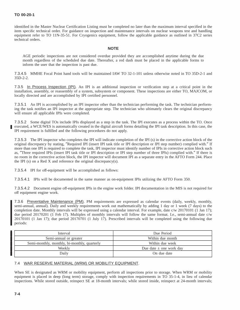
identified in the Master Nuclear Certification Listing must be completed no later than the maximum interval specified in theitem specific technical order. For guidance on inspection and maintenance intervals on nuclear weapons test and handlingequipment refer to TO 11N-35-51. For Cryogenics equipment, follow the applicable guidance as outlined in 37C2 seriestechnical orders.
NOTE
AGE periodic inspections are not considered overdue provided they are accomplished anytime during the duemonth regardless of the scheduled due date. Thereafter, a red dash must be placed in the applicable forms toinform the user that the inspection is past due.
7.3.4.5 MMHE Focal Point hand tools will be maintained IAW TO 32-1-101 unless otherwise noted in TO 35D-2-1 and35D-2-2.
7.3.5 In Process Inspection (IPI). An IPI is an additional inspection or verification step at a critical point in theinstallation, assembly, or reassembly of a system, subsystem or component. These inspections are either TO, MAJCOM, orlocally directed and are accomplished by IPI certified personnel.
7.3.5.1 An IPI is accomplished by an IPI inspector other than the technician performing the task. The technician perform-ing the task notifies an IPI inspector at the appropriate step. The technician who ultimately clears the original discrepancywill ensure all applicable IPIs were completed.
7.3.5.2 Some digital TOs include IPIs displayed as a step in the task. The IPI executes as a process within the TO. Onceexecuted, a WCE/WES is automatically created in the digital aircraft forms detailing the IPI task description. In this case, theIPI requirement is fulfilled and the following procedures do not apply.
7.3.5.3 The IPI inspector who completes the IPI will indicate completion of the IPI (s) in the corrective action block of theoriginal discrepancy by stating, ″Required IPI (insert IPI task title or IPI description or IPI step number) complied with.″ Ifmore than one IPI is required to complete the task, IPI inspector must identify number of IPIs in corrective action block suchas, ″Three required IPIs (insert IPI task title or IPI description or IPI step number of three IPIs) complied with.″ If there isno room in the corrective action block, the IPI inspector will document IPI as a separate entry in the AFTO Form 244. Placethe IPI (s) on a Red X and reference the original discrepancy(s).
7.3.5.4 IPI for off-equipment will be accomplished as follows:
7.3.5.4.1 IPIs will be documented in the same manner as on-equipment IPIs utilizing the AFTO Form 350.
7.3.5.4.2 Document engine off-equipment IPIs in the engine work folder. IPI documentation in the MIS is not required foroff equipment engine work.
7.3.6 Preventative Maintenance (PM). PM requirements are expressed as calendar events (daily, weekly, monthly,semi-annual, annual). Daily and weekly requirements work out mathematically by adding 1 day or 1 week (7 days) to thecompletion date. Monthly intervals will be expressed using a calendar interval. For example, date c/w 20170101 (1 Jan 17);due period 20170201 (1 Feb 17). Multiples of monthly intervals will follow the same format. I.e., semi-annual date c/w20170101 (1 Jan 17); due period 20170701 (1 July 17). Prescribed intervals will be completed using the following dueperiods:
Interval Due PeriodSemi-annual or greater Within due month
Semi-monthly, monthly, bi-monthly, quarterly Within due weekWeekly Due date ± one work dayDaily On due date
7.4 WAR RESERVE MATERIAL (WRM) OR MOBILITY EQUIPMENT.
When SE is designated as WRM or mobility equipment, perform all inspections prior to storage. When WRM or mobilityequipment is placed in deep (long term) storage, comply with inspection requirements in TO 35-1-4, in lieu of calendarinspections. While stored outside, reinspect SE at 18-month intervals; while stored inside, reinspect at 24-month intervals;
TO 00-20-1
7-4

while stored in a controlled environment (e.g. air-conditioned and humidity controlled), reinspect at 36-month intervals. TheGP/CC may designate more frequent or detailed inspection requirements.
NOTE
If end item technical data specifically addresses WRM inspections that guidance will take precedence over theguidance found above.
7.5 SE DOCUMENT ADMINISTRATION.
7.5.1 General Requirements. When maintenance responsibilities are divided among two or more work centers, theowning work center will ensure applicable forms are correctly initiated and maintained. The using individual is responsiblefor documenting the status and condition of the equipment as indicated on the AFTO Form 244/245. Ensure that documen-tation is entered in an approved MIS that feeds directly into REMIS. MIS must be approved by Lead Command and HQ AFA4L. When the form is closed out, it will be forwarded to the documentation section for filing disposition as prescribed inAFI 21-101, AFMAN 33-363, and this TO.
7.5.1.1 If a discrepancy renders the equipment unsafe or unfit for use, document the discrepancy with a Red X in the MIS(if available) and in the symbol block on Part V of the AFTO Form 244/245.
7.5.1.2 Discrepancies that are discovered on SE which do not impair the operation or use of the equipment will either becorrected by the SE repair activity, owning workcenter, or trainer maintenance personnel during the inspection, or a discrep-ancy entered in the maintenance record.
7.5.1.3 When maintaining, managing, and storing engine support and removal/installation/transportation equipment andtrailers, make sure to properly report status IAW AFI 21-103 and MAJCOM supplements. In addition:
7.5.1.3.1 Track all removal/installation/transportation trailers and adapters in an approved MIS.
7.5.1.3.2 Ensure equipment forms and MIS documentation are complete, accurate, and accomplished for all maintenanceand scheduled inspections.
7.5.1.3.3 Ensure status is accurately reflected in both the maintenance forms and the MIS.
7.6 AFTO FORM 244/245 DOCUMENTATION.
7.6.1 AFTO Form 244, Part I. Identifies the SE for which the form is maintained.
a. Block 1: Enter the nomenclature/model number.
b. Block 2: Enter the assigned AF registration/serial number. Leave blank if not applicable.
c. Block 3: Enter the identification number (a locally defined equipment-type identifier), if assigned. Leave blank if notassigned.
d. Block 4: Enter the field number. Leave blank if not applicable.
e. Block 5: Enter the Work Unit Code (WUC) if one is assigned. Leave blank if not applicable.
f. Block 6: Enter the assigned organization/workcenter or depot Resource Control Center (RCC).
g. Block 7: Enter the date the form was initiated to the left of the word TO. Once the form is closed out or the equipmentis turned into supply/salvage, and a new form initiated, enter the date to the right of the word TO.
h. Block 8: Leave blank if not applicable. This block may be used for MAJCOM or GP/CC specific requirements.
7.6.2 AFTO Form 244, Part II. Provides a means to document servicing inspections. Prior to use inspections are notdocumented unless required by the GP/CC or another publication.
TO 00-20-1
7-5

a. TIME column: Enter the time (in 24-hour military time) the service/prior to use inspection was accomplished. If theunit is equipped with a running time meter, the metered time shall be entered in place of the time of day. For SEinspected at hourly intervals, enter the daily/accumulated time.
b. INSP INIT column: Enter assigned employee number of the individual completing the inspection. If not assigned anemployee number the individual will use their first initial, middle initial (optional only if individual does not have asecond given name), and last initial.
c. DATE column. Enter the date the inspection was accomplished.
7.6.3 AFTO Form 244, Part III. Provides a means to document scheduled inspections.
a. INSPECTION REQUIREMENT column: Enter the type of inspection due, e.g., PH 1, PH 2, PE, special wheelbearing, wheel packing, lubrication etc. If directed by the GP/CC, include specific inspections for DIPE, other thanoperator inspections which may be documented in Part II.
b. INTERVAL column: Enter the next scheduled inspection interval, e.g., 30-, 60-, and 180-day, or 500-hour, etc.
c. DATE DUE column: Upon completion of an inspection, enter the next inspection due in the next open date due block.
d. DATE COMPL column: Enter the hour/date inspection was completed.
7.6.4 AFTO Form 244, Part IV. Provides a means to document a supervisory review of the form, if required by theGP/CC.
a. EMPLOYEE NUMBER column: Enter reviewer’s employee number (or first name initial, last name and grade if noemployee number).
b. DATE column: Enter the date the review was accomplished.
7.6.5 AFTO Form 244/245, Part V. Provides a means to document equipment discrepancies, corrective actions, andspecial inspection completion. The following conditions will be recorded in this part of the form:
7.6.5.1 Required TO maintenance action, including inspection and lubrication requirements where the inspection deemsthe item unserviceable IAW Paragraph 7.3.4. A condition exists that prevents a scheduled inspection/lubrication from beingaccomplished and an overdue inspection, including portions of inspections not accomplished during the scheduled inspection(e.g., workcard and/or workcard items not completed by the end of the due period).
7.6.5.2 Overdue time change, Master Configuration List (MCLs) and TCTOs.
7.6.5.3 Discrepancies discovered by the operator during operation of the system/equipment.
7.6.5.4 PART V will be completed as follows:
a. Block 9, T.O.: Enter the TO number or manufacturer’s manual number/title that covers the item identified in block 1.
b. Block 10, NSN: Enter the assigned national stock number or part number for item identified in block 1. Leave blankif not applicable.
c. Blocks 11 and 12: These blocks are left blank, unless approved for use by GP/CC.
d. DATE DISCOVERED column: Enter the date the discrepancy is discovered per Paragraph 3.5.
e. DISCOVERED BY column: The individual discovering the discrepancy will print their minimum signature and em-ployee number per Paragraph 3.6.
f. SUP DOC NUMBER column: Enter the base supply document number(s). This block is not required for units usingMIS and is a GP/CC option for all others. When two or more supply document numbers are needed to adequatelydefine base supply support for repairing a discrepancy, add all additional supply document numbers needed to correct
TO 00-20-1
7-6

the discrepancy after the statement of the discrepancy. If necessary, use of the next open DISCREPANCY block isauthorized. If the next block is used all adjacent blocks will be lined through. As these requisitions from base supplyare received by the requester, draw a single line through the document number to show its receipt.
g. SYMBOL column: Enter the applicable red symbol for the discrepancy.
h. DISCREPANCY column: Enter the discrepancy or maintenance action required. Only one defect will be entered ineach block for each job control or work order number; however, use as many blocks as necessary to completelydescribe a single discrepancy.
i. JOB CON/W.O. NO. column: Enter the job control or work order number assigned to the discrepancy. EXCEPTION:Tracking programs such as Tool Accountability System (TAS), used to track inspections/equipment, job control num-ber/work order numbers are not required.
j. CORRECTIVE ACTION column: Enter the description of the corrective action taken. For Red X discrepancies,include a sufficient technical data or governing directive reference to determine the work performed, (e.g. AFI, owner/user manual, TO number and paragraph/figure number for conventional TOs, function number/fault code for MISbased TOs). IPE is excluded from this requirement since the TO reference is listed on the equipment. GP/CCs mayspecify additional minimum TO reference. If more space is needed to make this entry, use the next open block.
k. DATE CORRECTED column: Enter the date the discrepancy is corrected.
l. CORRECTED BY column: The individual clearing a Red Diagonal will enter their minimum signature and employeenumber in this block and last name initial over the red symbol in the symbol column. The individual correcting a RedX discrepancy will enter their minimum signature and employee number in this block.
m. INSPECTED BY column: The individual authorized to clear a Red Dash or Red X symbols will enter his/her mini-mum signature and employee number in this block and last name initial over the red symbol in the symbol column.
NOTE
Individuals using an electronic AFTO Form 244, that prohibits initialing over the red symbol, will enter theirminimum signature and employee number and NOT initial over the red symbol in the SYMBOL column.
7.6.6 AFTO Form 245. This optional form provides a continuation to Part V of the AFTO Form 244. This form will becompleted using the same instructions as provided for Part V of the AFTO Form 244.
7.6.7 Disposition Instructions. After the AFTO Form 244/245 is closed out, forward the old form to the responsibledocumentation activity for filing and disposition. (See AFMAN 33-363.) If the AFTO Form 244 is missing, lost or damaged,create anew form with the words “OLD FORMS LOST” written on top margin of the front side of the form with briefexplanation, if known.
7.6.8 Closing Out AFTO Form 244/245. The AFTO Form 244/245 will be closed out and a new form initiated whenadditional recording space is required. The following procedures apply:
7.6.8.1 On the new forms transcribe entries in block 1 through block 6 from the old form and enter the current date inblock 7 to the left of the word TO. Enter all carried forward inspections due in Part III and all carried forward discrepanciesand information in Part V from the old form. When carrying the discovered by block forward, print the name and employeenumber of the individual who originally discovered the discrepancy.
7.6.8.2 When closing out the old AFTO Form 244/245, enter the current date in block 7 to the right of the word TO. Theindividual carrying forward entries, enters “CF” (carried forward) followed by their first and last name initials in the DATECOMPL block of Part III. In Part V enter “CF” and minimum signature in the corrective action block for each opendiscrepancy carried forward.
TO 00-20-1
7-7

7.6.8.3 Designation of SE as “formerly contaminated” with chemical, biological or radiological agents will be carriedforward with information regarding the contamination date, type of agent, decontamination date, type of decontaminants,and decontamination procedures. Equipment markings will ensure that all handlers of the formerly contaminated parts areaware of possible residual contamination hazards. SE not repaired and replaced must be destroyed as hazardous material(currently by incineration). See AFTTP (1) 3-2.37.
NOTE
A Red C indicates the equipment has been contaminated by a chemical, biological or radiological agent.
TO 00-20-1
7-8
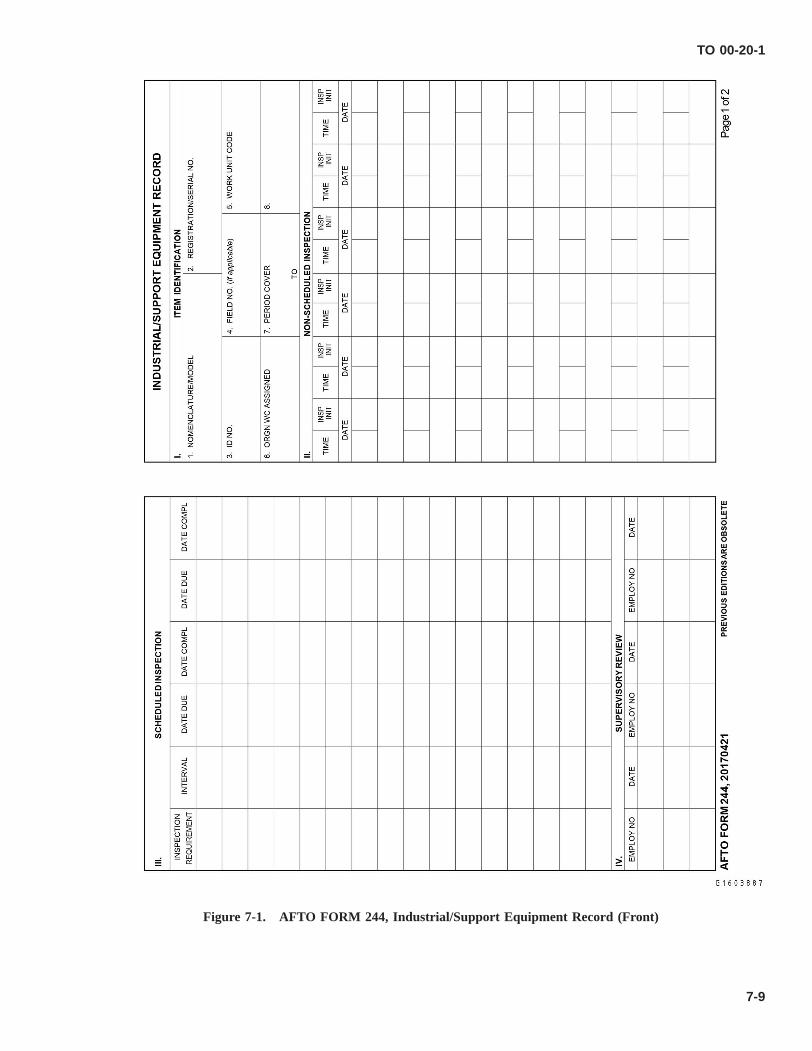
Figure 7-1. AFTO FORM 244, Industrial/Support Equipment Record (Front)
TO 00-20-1
7-9
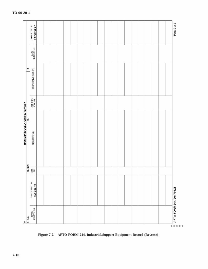
Figure 7-2. AFTO FORM 244, Industrial/Support Equipment Record (Reverse)
TO 00-20-1
7-10

Figure 7-3. AFTO FORM 245, Industrial Support Equipment (Continuation) (Front)
TO 00-20-1
7-11

Figure 7-4. AFTO FORM 245, Industrial Support Equipment (Continuation) (Reverse)
TO 00-20-1
7-12

CHAPTER 8TRANSFER, STORAGE, AND DEPOT MAINTENANCE
8.1 TRANSFERRING AEROSPACE VEHICLES.
8.1.1 Requirements. Headquarters Air Force Materiel Command (AFMC) manages the assignment of aerospace vehiclesas directed by HQ USAF. When a transfer is directed, it will be made within 30 days of receipt of notification by theMAJCOM to which the aerospace vehicle is assigned. If additional time is required to affect the transfer, forward a requestfor authority to delay the transfer for a specific number of days to the AF Aerospace Vehicle Distribution Office (AVDO)IAW AFI 21-103, stating reasons for the delay. Refer to AFI 21-101 for additional requirements for aerospace vehicletransfer requirements.
8.1.1.1 Tactical movement of complete combat elements and temporary loans of aerospace vehicles between Air Forceorganizations do not come under the provisions of this technical order. Responsibility for condition, maintenance, anddocumentation, in the case of temporary loans, will be as agreed to by the commanders concerned.
8.1.1.2 After completing the pre-transfer maintenance, including Functional Check Flights (FCF) if required, the possess-ing activity will notify the gaining unit of its availability for transfer and will restrict the aerospace vehicle from further use.The aerospace vehicle will be maintained in suitable condition to prevent delay of the ferry or transfer flight.
8.1.1.3 List installed guns on AF Form 2692, regardless of whether or not they are listed in the -21 technical order. Whenthe losing maintenance activity is transferring aerospace vehicles with small weapon(s) (50 caliber or under), they will notifyLogistics Readiness Squadron, Materiel Management Flight, Customer Support Section, Equipment Accountability Element,of the weapon(s) serial number(s) being transferred.
8.1.1.4 When transferring aerospace vehicles to agencies outside the Air Force, AFMC will issue special instructions forTime Compliance Technical Order (TCTO) compliance and maintenance requirements for the transfer. When AeronauticalSystems Center (ASC) or AFMC aerospace vehicles are placed on bailment to contractors, special instructions necessary forthe preparation of the vehicle for delivery to the bailee (recipient) and its return to the Air Force will be included in thebailment agreement.
8.1.1.5 Aerospace vehicles, being prepared for return to service after removal from storage by MAJCOM other thanAFMC, will not be processed through AFMC depot facilities unless inspections indicate that depot maintenance is required.All required maintenance will be accomplished by the MAJCOM removing the aerospace vehicle from storage. Depotmaintenance requirements will be negotiated with AFMC.
8.1.1.6 Aerospace vehicles directed to be transferred while at a depot/contractor facility will be returned to the losingorganization upon completion of the work for the accomplishment of the transfer inspection and maintenance, unless theusing commands and the Single Manager (SM) agree that transfer requirements will be accomplished by the depot facility.For missiles, the depot/contractor accomplishes the transfer inspection.
8.1.1.7 When AFMC depot/contractor facilities perform transfer requirements for a losing organization, they will report allaccountable equipment shortages to the losing organization. The AFMC/contractor facility will include a copy of the re-ported shortages with the aerospace vehicle historical documents/depot work package. The losing organization will beresponsible for the shipment of shortages to the gaining organization without delay. All shipments will be clearly marked andidentified as equipment shortages for the aerospace vehicle type and serial number transferred. When the losing organizationis unable to supply all reported equipment shortages, corrective action will be the responsibility of the MAJCOM.
8.1.1.8 The AFTO Form 345 (Figure 8-1 and Figure 8-2), outlines requirements to be accomplished in conjunction withthe transfer. Use of the AFTO Form 345 is optional for missile units. Complete this form and forward the original with theaerospace vehicle and retain the duplicate. Form entries are self- explanatory and serve as a certification of the requirementslisted. List any special requirements individually under item 14. If applicable, waivers outlined in subsequent paragraphs willbe listed in block 15, REMARKS, with a reference to the authorizing agreement.
TO 00-20-1
8-1

8.1.1.8.1 Ensure the maintenance group commander (or equivalent) certifies each transferred aerospace vehicle for con-dition, completeness of equipment (to include aerospace vehicle Data Plate), and serviceability; annotate this certification onthe AFTO Form 345.
8.1.1.9 When aerospace vehicles are transferred from one AF organization to another, the losing organization accom-plishes the following:
8.1.1.9.1 Ensure all correctable discrepancies are cleared (except transfer to Aerospace Maintenance and RegenerationGroup (AMARG)).
8.1.1.9.2 If over 50 percent of the inspection time has elapsed by the established transfer date, then accomplish the nextscheduled hourly post-flight, phase, periodic, minor or major inspection on the aerospace vehicle or missile. Accomplishinspections as prescribed in the applicable -6 TO, maintenance manual, or workcard set, including scheduled/special inspec-tions and TCIs as required.
8.1.1.9.3 If parts are not available and valid delayed discrepancies exist, include these discrepancies with the historicaldocuments that are transferred.
8.1.1.9.4 Determine if depot maintenance is required, and if so, arrange for its accomplishment in accordance withParagraph 8.1.1.10.
8.1.1.9.5 Comply with all outstanding TCTOs for kits on-hand or obtainable. If the TCTO cannot be accomplished by theestablished transfer date, or requisitioned kits have not been received, comply with the provisions of TO 00-5-15.
8.1.1.9.6 Change the engines as required under the provisions of TO 2-1-18.
8.1.1.9.7 Accomplish a Functional Check Flight (FCF) when required in accordance with the MDS specific -6 TO,maintenance manual, or when required by a TCTO.
8.1.1.9.8 Ensure all associated equipment is transferred with the aerospace vehicle and properly account for equipmentshortages.
8.1.1.9.9 Ensure open discrepancies requiring parts include the applicable TO references (e.g. illustrated parts breakdowntechnical order number, figure, and index).
8.1.1.9.10 Perform a complete document review of the transferring aerospace vehicle and associated equipment, to in-clude historical records. Make corrections as required.
8.1.1.9.11 Due to varying circumstances and conditions, the following deviations are authorized:
8.1.1.9.11.1 A MAJCOM having jurisdiction over both the losing and gaining organization may waive or modify any orall of the above requirements.
8.1.1.9.11.2 For transfers from one MAJCOM to another, the gaining MAJCOM may waive any or all of the requirementsstated above or modify them under agreement with the losing command.
8.1.1.10 If the aerospace vehicle requires unprogrammed depot/contractor work prior to transfer, or the losing organiza-tion requires maintenance assistance, arrangements will be made by the losing organization with the appropriate SystemProgram Director (SPD) under the provisions of TO 00-25-107. In the event the aerospace vehicle must be delivered to adepot/contractor facility for work accomplishment, the losing organization will accomplish all of the requirements of Para-graph 8.1.1.9, prior to delivery of the aerospace vehicle. The losing MAJCOM in coordination with the SM may waive,modify or request certain requirements of Paragraph 8.1.1.9 to be accomplished by the depot/contractor facility.
8.1.1.11 Losing organizations preparing aerospace vehicles for overseas transfer will provide the AFMC facility, whereaerospace vehicles will be staged or shipped, at least 30 days advance notification of each aerospace vehicle to be processed.This requirement is exempt from Report Control Symbol (RCS) licensing.
TO 00-20-1
8-2

8.1.1.12 AFMC depot facilities preparing aerospace vehicles and missiles for transfer will accomplish all work necessaryto ensure they are in a serviceable condition. If these aerospace vehicles are equipped with engines that have been in storage,the engines may be used, provided the depot facility complies with all existing TCTOs applicable to the engine and engineaccessories. Aerospace vehicles and missiles will not be reported as available for transfer until all applicable requirementsare completed or until waivers have been authorized. Depot facilities preparing aerospace vehicles removed from storage forsubsequent delivery to using activities initiate or complete the maintenance documents prior to delivery.
TO 00-20-1
8-3

Figure 8-1. AFTO FORM 345, Aerospace Vehicle Transfer Inspection Checklist and Certification (Front)
TO 00-20-1
8-4

Figure 8-2. AFTO FORM 345, Aerospace Vehicle Transfer Inspection Checklist and Certification (Reverse)
TO 00-20-1
8-5

8.1.2 AFTO Form 290, Aerospace Vehicle Delivery Receipt. Use the AFTO Form 290 (Figure 8-3) to transfer aero-space vehicles and to furnish a record of selected equipment that will be transferred with the aerospace vehicles.
8.1.2.1 AFTO Form 290 serves as a vehicle receipt for delivery pilots or transporters and as a receipt for aerospacevehicles, selected equipment, and paperwork checklist. The form:
• Is not required if aerospace vehicles are moved by airlift or surface transportation.
• May be used in addition to the (required) DD Form 1149, if directed by AFMC.
• Lists the only items required to be physically checked by the delivery aircrew, transporter or the gainingorganizations.
8.1.2.2 Prepare the form using the following guidelines:
8.1.2.2.1 The losing organization (such as the AVDO) at factories, depots, modification centers, bases, etc.) or the deliverycontrol officer prepares this form. The losing organization fills in the heading of the form, including:
a. AIRCRAFT/MISSILE MODEL
b. SERIAL NUMBER
c. ACCOUNT/CONTRACT NO.
d. PROJECT AND/OR PRIORITY
e. FLT/TRANSPORTATION ORDER NO. (when known)
f. CLASSIFIED MATERIAL INSTALLED ON AIRCRAFT/MISSILE: List classified equipment installed. Enter “None”if no classified material is installed.
g. RECEIVING ORGANIZATION
h. RELEASED BY (Unit, Base, and Command).
i. PICKUP POINT
j. PICKUP DATE
k. Column B: List the quantity of each item placed on each vehicle.
8.1.2.3 Upon accepting the aerospace vehicle for delivery, including responsibility for paperwork and equipment listed incolumn B of the checklist, the authorized representative of the Transporting/Ferrying organization will sign the deliveryreceipt in the space provided. The representative indicates that each item has been checked by placing a check in column Cand initials at the bottom of the column.
8.1.2.3.1 In many cases, the aircrew or transporter is the authorized representative of the gaining organization. In thiscase, they will complete the AFTO Form 290 just before departing with the aerospace vehicle.
8.1.2.3.2 Delivery control or transportation officers at factories or modification centers are responsible for checking theitems listed and signing the AFTO Form 290.
8.1.2.3.3 Space is provided on AFTO Form 290 for three intermediate stops, where the aircrew or transporter does notstay with the aerospace vehicle or missile and needs to be relieved of the responsibility for the items on the checklist.
8.1.2.3.3.1 If more than three intermediate stops are made, use an additional set of forms and attach them to the first form.
TO 00-20-1
8-6

8.1.2.3.3.2 Immediately after the aerospace vehicle arrives at such an activity, the authorized activity representative andthe aircrew or transporter checks the items.
8.1.2.3.3.3 The activity representative places a check in the first open intermediate activity IN column and initials at thebottom of the column if all items shown in column B, or subsequently noted, are present.
8.1.2.3.3.4 If an item is missing, the authorized activity representative enters the correct figure in the IN column, and theaircrew or transporter initials the corrected figure and explains in the remarks section of the form. After all items arechecked, the activity commander is responsible for guarding against loss of such equipment or papers.
8.1.2.3.3.5 The aircrew or transporter checks the items in the checklist before the vehicle leaves. The aircrew or trans-porter checks the proper intermediate activity OUT column, and initials at the bottom of the OUT column. The activityrepresentative also initials this column. Any difference must be explained by the activity representative in the remarkssection of the form, together with their signature, grade, and activity.
8.1.2.3.3.6 When the aerospace vehicle arrives at the end destination, the authorized representative of the gaining orga-nization checks column J and initials at the bottom of the column if all items shown in column B, or subsequently noted, arepresent.
8.1.2.3.4 If an item is missing, the representative enters the corrected figure IN and the aircrew or transporter initials thecorrected figure and explains in the remarks section of the form.
8.1.2.3.5 The authorized representative of the gaining organization then signs the receipt in the space provided on theform.
8.1.2.4 Copies are prepared by the losing organization and distributed as follows:
a. Copy 1 - Home station.
b. Copy 2 - Aircrew or transporter.
c. Copy 3 - Recipient.
d. Copy 4 - Losing organization.
e. Copy 5 - Air Force Plant representative or chief of the Defense Contract Administration Services Offices (DCASO)where the contractor facility is located, marked for the property administrator. This copy is required if aerospacevehicles are delivered to the contractor facility.
8.1.2.5 Reducing the number of copies is permissible according to the needs of the individual command or by mutualagreement between commands concerned.
TO 00-20-1
8-7

Figure 8-3. AFTO FORM 290, Aerospace Vehicle Delivery Receipt
TO 00-20-1
8-8

8.1.3 AMARG Desert Operations and Maintenance Storage Activities. Procedures governing corrosion control, pres-ervation, maintenance in preservation, represervation, de-preservation of aircraft and related equipment of aircraft, engines,and auxiliary power units, stored at AMARG can be found in TO 1-1-686.
8.1.3.1 Personnel performing maintenance on assets in storage will use the technical data extracts per TO 00-5-1. Generalsafety precautions and instructions must be understood and applied during these maintenance operations to ensure personnelsafety and protection of equipment.
8.1.3.2 In-storage maintenance begins once an aircraft system is breeched/deactivated (e.g. electrical, hydraulic, fuelsystems) and continues until such systems are reactivated and landing gear systems are restored to operational condition.
Mechanics must coordinate any steps that cannot be safely performed with their supervisor to ensure safeoperations.
8.1.3.2.1 Mechanics performing AMARG Desert Operations and Maintenance will follow technical guidance as closely aspossible to accomplish the operation on the Work Control Document (WCD). Steps may be omitted during maintenanceoperations when assets are in non-standard configurations, safety is not compromised and does not affect task completion.Only trained and certified technicians are permitted to omit steps when necessary. Specific AMARG Desert Operationtraining will be completed and documented for technicians utilizing this guidance.
8.1.3.3 Specific AMARG Desert Operation training will be developed locally by AMARG and scheduled and tracked inTraining Scheduling System-Production Acceptance Certification. Training will include unique AMARG Reclamation, De-militarization and Disposal conditions and environmental concerns.
8.1.3.4 When aerospace vehicles are transferred from one AF organization to another, the losing organization accom-plishes the procedures in Paragraph 8.1.1.9. See Paragraph 8.1.6 for preparation of aerospace vehicle to be transferred forinactive long-term storage at AMARG.
8.1.4 Preparation of Aerospace Vehicles for Delivery to a Depot/Contractor Facility.
8.1.4.1 The losing organization will prepare aerospace vehicles, scheduled for delivery to a depot/contractor facility formodification and/or maintenance, in accordance with the following guidance:
8.1.4.1.1 Perform all work necessary to place the aerospace vehicles in an airworthy or transportable condition fordelivery to the facility. Remove munitions unless a specific agreement is established between the base and the facility.
8.1.4.1.2 If the aerospace vehicle is to be returned to the same MAJCOM, only that equipment affected by the modifica-tion and/or maintenance need accompany the aerospace vehicle. The losing organization will comply with AFI 21-103requirements.
8.1.4.1.3 Comply with the requirements in the modification and/or maintenance work specification and workload agree-ment which apply to the possessing unit. The work specification and workload agreement are a negotiated contract betweenthe possessing MAJCOM and the ALC responsible for establishing the work requirement. The depot/contractor accom-plishes those items contained in the work specifications. Additional requirements are identified on AFTO Form 103.
8.1.4.2 TCTO kits on hand at base level, which will be installed by the facility, (as agreed to between the SM and theusing MAJCOM), will be forwarded to the facility. When kits are forwarded, they will either accompany the aerospacevehicle or be properly identified with the aerospace vehicle serial number and made available to the facility in time to avoidunnecessary delays in-processing.
8.1.4.3 Bases transferring aerospace vehicles that have been in storage to depot facilities may attach any local documentsthat were used during the aerospace vehicle’s storage period for recording applicable TCTOs to the aerospace vehicle forms.If attached, it will be noted on the AFTO Form 781A or other appropriate forms.
TO 00-20-1
8-9

8.1.4.4 Forward a copy of the automated products with an aerospace vehicle, engine, or engine module which is beingtransferred to a depot for PDM, MOD or ACI. The automated products will be identified by work load agreements. Theaerospace vehicle or engine records section ensures all information which affects the aerospace vehicle, engine or enginemodule historical records, such as accessory and TCIs, are documented on the automated product.
8.1.4.5 When all pertinent aerospace vehicle, engine or engine module historical information has been documented on theautomated products, the aerospace vehicle or engine scheduling branch chief certifies that all entries are complete. When theaerospace vehicle, engine or engine module (as applicable) returns to the unit of assignment, forward the certified automatedproducts to the aerospace vehicle or engine records section where the MIS data file will be updated based on the informationprovided by the automated products. Depots will retain a copy in the depot aerospace vehicle or engine records section for180 days.
8.1.5 Preparation of Aerospace Vehicle for Transfer by One-Time Flight. When instructions are received for transferof an operational or a stored aerospace vehicle by ″one-time flight,″ the transferring (losing) organization will conduct athorough inspection of the aerospace vehicle, installed engines, and equipment that is essential for a safe transfer flight. Theactivity preparing the aerospace vehicle will determine the extent of inspection requirements. The transferring organizationwill:
8.1.5.1 Accomplish the necessary work required to place the aerospace vehicles in an airworthy condition, includingTCTOs for which the time limit has expired. If required, the transferring (losing) organization may request authority fromthe SM to waive compliance for TCTOs.
8.1.5.2 The GP/CC will consider an FCF to verify work accomplished under Paragraph 8.1.5.1 and to verify the conditionof all essential flight systems to ensure that the aerospace vehicle is airworthy for the intended one-time flight. Such FCFswill be accomplished under the provisions of TO 1-1-300 and the applicable portions of the FCF checklists, -6 TO,maintenance manual, and AFI 21-101.
8.1.6 Preparation of Aerospace Vehicle to be Transferred for Inactive Long-Term Storage. Transfer of aircraft forlong-term storage will be accomplished IAW this TO, AFI 21-103, and established workload agreement (WLA) and state-ment of work (SOW) between System Program Office (SPO) and 309 AMARG.
8.1.6.1 Prior to transfer, losing organization will coordinate with 309 AMARG Business Office to:
8.1.6.1.1 Ensure an approved AF Form 913, has been received by 309 AMARG.
8.1.6.1.2 Ensure WLA and SOW has been approved and all requirements complied with.
8.1.6.1.3 Ensure funds are in place to receive and prepare aircraft for storage.
8.1.6.1.4 Schedule arrival date and time.
8.1.6.1.5 Email photograph of aircraft data plate and its location to [email protected].
8.1.6.1.6 Forward a digital copy of MIS automated products with an aerospace vehicle, engine, or engine module whichis being transferred for storage. The losing organization must ensure all information which affects the aerospace vehicle,engine or engine module historical records, such as accessories, modifications and TCIs, are documented. Automated prod-ucts should accompany the permanent records, or may be emailed to [email protected].
8.1.6.2 AFTO Form 290 will be accomplished IAW Paragraph 8.1.2.
8.1.6.2.1 Classified equipment shall be removed prior to transfer to storage, unless required for safety of flight. Annotateremoval on AFTO Form 781A.
8.1.6.3 Aircraft/Missile Equipment Inventory (-21) Disposition.
8.1.6.3.1 Section I, Maintenance Safety and Protection Equipment: All items shall remain with the aircraft for safestorage. Missing items should be identified on AF Form 2692.
TO 00-20-1
8-10

8.1.6.3.2 Section II, Alternate Mission Equipment: Not required with aircraft, but may be installed. Installed items shouldbe addressed in SOW.
8.1.6.3.3 Section III, Crew and Passenger Support Equipment: Only as required for transfer flight. No additional lifesupport equipment should accompany aircraft (e.g. rafts)
8.1.6.4 Aircraft data plates are required upon storage induction. Assets missing data plates will be reported to SecurityForces and coordinated with losing organization and SPO for replacement. Asset will be received and secured by 309AMARG, but will not proceed with induction and preservation until valid data plate is received.
8.1.7 Preparation of Aerospace Vehicle to be Transferred Sold or Disposed. The Foreign Military Sales agreement,AFMC guidance, and/or AFI 23-101, provide direction for preparation of aerospace vehicles for transfer or disposal.
8.1.7.1 Unless otherwise specified, aerospace vehicles directed for flight delivery to a civilian or federal agency will beprepared for One-Time Flight in accordance with the provisions of Paragraph 8.1.5.
TO 00-20-1
8-11/(8-12 blank)


CHAPTER 9MAINTENANCE HISTORICAL DOCUMENTATION
9.1 GENERAL.
This chapter prescribes the requirements for historical documentation. Historical Documentation is the permanent record ofsignificant maintenance actions on aerospace equipment.
9.1.1 Historical Documentation Requirements. Historical documentation requirements are applicable to field, organic,and contractor depot-level activities. Item Managers or program managers determine which items in the MDS specific -6 TOneed historical reporting, and inform the Single Manager (SM) so they can be identified for reporting.
9.1.1.1 Ship historical documents with the aerospace equipment or component to disposal, storage activity, next usingactivity or depot, unless otherwise directed.
9.1.1.2 Historical documentation will be made in the MIS whenever available. When not available use the AFTO Form 95process explained in Paragraph 9.3.1. Automate the AFTO Form 95 in the Maintenance Information System (MIS) as soonas it is available. Discard the hardcopy form once information is input into the MIS.
9.1.1.3 Document the following historical events:
9.1.1.3.1 TCTO compliance. Document TCTO non-compliance due to modified or removed systems in which an AF Form1067, was approved. All AF Forms 1067 must be maintained in the aerospace equipment’s historical files.
9.1.1.3.2 TCIs.
9.1.1.3.3 Data on damage to fracture critical structure including fatigue-related damage, the location and extent of thedamage, repairs accomplished, repair authority, repairing activity, and date of repair. Include data concerning special require-ments, procedures, and intervals.
9.1.1.3.4 Removal and replacement of aerospace equipment fracture critical structure including fixed wings and stabiliz-ers.
9.1.1.3.5 Remarks concerning special service test equipment installed or removed.
9.1.1.3.6 Data on severe corrosion, its location, extent, and treatment accomplished or required.
9.1.1.3.7 Circumstances regarding mishaps, the extent of damage, and repairs accomplished.
9.1.1.3.8 Weather damage to aerospace equipment.
9.1.1.3.9 Data on overstresses and hard landings.
9.1.1.3.10 Engine removal or installation for fuel contamination in both the aircraft and engine historical records withamount, kind of contamination, and applicable special inspection requirements.
9.1.1.3.11 Replacement of time recording devices. Record the operating time from the removed meter, and the time on thenew meter if more than zero.
9.1.1.3.12 Data on chemical, biological or radiological contamination including contamination date, type of contaminate,decontamination date, type of decontaminants, and decontamination procedures used. Records will be maintained for thelifecycle of the equipment (including removed/installed parts).
9.1.1.4 Historical Engine Documentation. Requirements are as follows:
TO 00-20-1
9-1

9.1.1.4.1 Enter the aerospace vehicle serial number, vehicle total time, and engine position on the engine record at time ofinstallation. If the engine is not zero time, include the previous operating time.
9.1.1.4.2 Upon engine removal, enter the new vehicle total-time and engine-time since overhaul on the engine record.
9.1.1.4.3 Enter the engine time at removal, or the time at transfer if different on the engine record.
9.1.1.4.4 Bases with modular engines record the Total Operating Time and a new total low 2239 cycle fatigue. Report theengine cycles when the compressor or compressor disks are removed. Cycle records are only applicable to those enginesnoted in the MDS specific -6 TO. The method for determining cycles is outlined in the -1 or -2 manuals.
9.1.1.4.5 Set the engine Time Since Overhaul (TSO) to zero on the historical records for engines processed through theorganic or contractor depot for overhaul.
9.1.1.4.6 Do not zero engine components having a maximum life based on cycles or time in the MDS specific -6 TO.
9.1.1.4.7 Record entries for foreign object damage, internal damage, overspeed, overtemperature or removal of compo-nents for maximum service life.
9.1.1.4.8 Record removal and replacement of engine accessories, defined as class A-2 and B-2 accessories by this TO, inthe engine historical record.
9.1.1.4.9 Supplemental historical records are required for engine components listed in the MDS specific -6 TO. Thesesupplemental records must remain with the engine while the components are installed and must be updated and forwardedwhen the component is removed. These records must contain the total operating time for the component and the cycles, asapplicable. The supplemental record must contain the engine serial number as well as the component serial number.
9.1.1.4.10 Document the total accumulated cycle entry for each record immediately following, and on the same line as thetotal time. This line should read as follows: TT _____, TSO _____, Cycles _____.
9.1.1.4.11 For modular engines, record a line entry indicating the reason for a test stand run and the results.
9.1.1.4.12 Initiate a historical documentation record for Quick Engine Change (QEC) kits for applicable aerospace ve-hicles.
9.1.1.4.13 When engines are shipped to or from the depot, the maintenance facility that preserves the engine ensures thatall basic engine components have been accounted for. Make an entry verifying that the basic items listed in TO 2J-1-24 havebeen included. This will include the name, rank, base, office symbol, and telephone extension of the person making theverification. Make a separate entry for all missing items listing the National Stock Number (NSN), nomenclature, dispositionof the removed part, and justification for the missing part not being included.
9.1.1.4.14 Document pertinent manufacturing data for jet engine turbine wheels.
9.1.1.4.15 Documentation is mandatory for certain selected afterburner/augmentors/jet engines as indicated by the appli-cable MDS specific -6 TO scheduled inspection and maintenance. Document in units where jet engines, jet engine adjustablenozzles or thrust reversers are involved in frequent rotation from one aerospace vehicle to another. When documentingafterburner data for the J-79-15/17, the installation and operating time data section will reflect sorties rather than time in theapplicable blocks.
9.1.1.4.16 Record the built-up engine weight and the weight of afterburners/augmentors. Consult TO 1-1B-50 for thelisting of certain aerospace vehicles that do not require an entry in CHART C of the weight and balance book for engines orafterburner/augmentors.
9.1.1.5 In-Flight Engine Shutdowns. Requirements are as follows:
a. Low oil pressure: Include how long the engine operated at that pressure and how long engines wind milled.
b. Overtemps: Include maximum temperature and how long the engine operated at that temperature.
TO 00-20-1
9-2
c. Compressor stalls, rollbacks, seizures, and flameouts: Describe the conditions when they occurred.
9.1.1.6 Engine Transfers. When transferring engines between units or centralized repair facilities, document all basicengine components accounted for as prescribed in TO 2J-1-24, to include QEC kit items accounted for in the applicable -10.
9.1.1.7 Pylon Historical Reporting. Requirements are as follows:
9.1.1.7.1 Enter the total accumulated equivalent power cycles at the time of pylon removal. (TO 1C-5A-6). Equivalentpower cycles are cumulative for the life of the pylon and are carried forward at overhaul or modification.
9.1.1.7.2 Enter all other significant data concerning inspection results, waivers, repairs, and configuration changes whennot recorded in automated systems.
9.1.1.8 Propeller Historical Reporting. Requirements are as follows:
9.1.1.8.1 For propeller components indicated by the -6 TO, document the following information when installed on theaircraft: aircraft serial number, aircraft time, and engine position.
9.1.1.8.2 For propeller blades, record the hub serial number at time of assembly.
9.1.1.8.3 For all installations and removals, record the propeller end item serial number, end item time since overhaul, andtime since overhaul for all components.
9.1.1.8.4 Record any TCTOs, special inspections or maintenance actions performed that could have a future bearing onpropeller or propeller component operation.
9.1.1.9 Landing Gear and Strut Historical Reporting. Requirements are as follows:
9.1.1.9.1 For gear installation, show the aircraft serial number, gear position, date installed, airframe time, and airframelandings.
9.1.1.9.2 For strut installation, show total hours installed, landings accumulated, and total time since overhaul.
9.1.1.9.3 Field level seal replacement, assembly and disassembly of landing gear struts/oleos are considered historicalevents and must be annotated on the AFTO Form 95.
9.1.1.10 Helicopter Components Historical Reporting. Specified (per applicable aircraft technical data) requirementsare as follows:
9.1.1.10.1 Will contain both the operating time for the aircraft and the components.
9.1.1.11 KC-135 Boom Historical Reporting. Requirements are as follows:
9.1.1.11.1 Whenever a MDS specific -6 TO inspection is required, document inspection and results on boom AFTO Form95. Upon installation of boom, document new boom serial number on aircraft AFTO Form 95, and aircraft tail number onnew boom AFTO Form 95.
9.1.1.12 KC-135 MPRS Pod Historical Reporting. Requirements are as follows:
9.1.1.12.1 Document all Line Replaceable Unit (LRU) changes, TCTOs, installation/removal on aircraft, etc. on podAFTO Form 95 (G081-9037).
9.1.1.13 Guns and Gun Barrels. Historical reporting will contain the number of rounds fired.
9.1.1.14 Munitions Materiel Handling Equipment. Requirements are as follows:
9.1.1.14.1 Document all replacement of major components or sub components that are deemed defective or damagedbeyond normal wear and tear.
TO 00-20-1
9-3

9.1.1.14.2 Document all TCTO, one-time inspection, and special inspections.
9.1.1.15 Depot and contract maintenance are required to document all NWRM and classified items removed (e.g. canni-balized, reclaimed, harvested) from reparable Next Higher Level Assemblies (NHA) assets on AFTO Form 95. Utilize anexisting AFTO Form 95 or generate a new one when required. At a minimum, the national stock number, part number, serialnumber and quantity of each item reclaimed or cannibalized from each NHA asset, will be recorded on the AFTO Form 95.
9.1.1.16 Temporary Fuel Leak Repair Historical Reporting. Document data regarding temporary repair of fuel leaks inintegral wing tanks on the AFTO Form 427 and AFTO Form 428, as prescribed in TO 1-1-3.
9.2 NON-AUTOMATED PROCEDURES.
9.2.1 AFTO Forms. When MIS is not available, use the AFTO Forms described in this section to collect data manually.Use enough detail to update the MIS.
9.2.1.1 Aerospace vehicles and engines maintained under FAA rules may use Airframe and Engine Log Books in lieu ofautomated history or AFTO Form 95 as long as their use is consistent. When any system or item is being shipped to anynon-Air Force agency to include Defense Reutilization and Marketing Office (DRMO), include a hard copy of the historicaldocumentation to comply with Flight Safety Critical Aerospace Vehicle Parts (FSCAP) Program per AFI 21-101. A historicalprintout from REMIS or CEMS suffices for this requirement. Applicable information provided in non-USAF log books ordocuments not prescribed for Air Force use will be verified and transferred to appropriate Air Force documents. Aerospacevehicles maintained to FAA certification may use FAA log books. Except when directed by SM, Air Force organizations arenot required to maintain Navy log books.
9.3 AFTO FORM 95, SIGNIFICANT HISTORICAL DATA RECORD.
(Figure 9-1.) The AFTO Form 95 is a document for maintaining a permanent history of significant maintenance actions onend items of equipment as determined by the single manager. Include data on equipment contamination by chemical,biological or radiological agents, annotating date and type of contamination, date and type of decontamination, and decon-taminant used. This information will portray those conditions that could have a bearing on future maintenance or tracking ofthe aerospace equipment.
9.3.1 AFTO Form 95 Entries. Document the AFTO Form 95 as follows:
9.3.1.1 PAGE____ OF PAGES____: Enter the appropriate page numbers.
9.3.1.2 Block 1, MISSION DESIGN SERIES/TYPE, MODEL AND SERIES/PART NUMBER: Enter the MDS or typedesignator of the aerospace equipment. Enter the part number assigned to the item. For quick-engine change kits, enter theterm “QEC.” For helicopter blades and tail rotors enter the NSN and part number.
9.3.1.3 Block 2, MANUFACTURER: Enter the name of the manufacturer. For helicopter blades and tail rotor blades, thedate of manufacture will follow the name.
9.3.1.4 Block 3, SERIAL NUMBER: When assigned, enter the serial number of the item identified in block 1. Example:95-1428 or 89-1429.
9.3.1.5 Block 4, ACCEPTANCE DATE: Enter date the equipment was accepted by the Air Force. If unknown, enter“unknown.”
9.3.1.6 Column A, DATE: Enter the date the maintenance action or inspection is accomplished.
9.3.1.7 Column B, REMARKS: Enter the applicable information, using as many lines as necessary, to document signifi-cant data. If documenting TCI information in this section, ensure part number, serial number, and if applicable, lot numberis included.
9.3.1.8 Column C, ORGANIZATION: Enter the organization that accomplished the maintenance or inspection.
TO 00-20-1
9-4

9.3.2 AFTO Form 95 Special Applications. The MAJCOM or GP/CC may prescribe additional uses of the AFTO Form95. Forms prepared and maintained for MAJCOM or GP/CC requirements will accompany the equipment upon transfer.However, upon review of the forms package, dispose of these forms in accordance with AFMAN 33-363, if not required.When such forms are forwarded with the equipment to overhaul facilities, update by the overhaul facility is not mandatory.
9.4 MAINTENANCE AND DISPOSITION OF HISTORICAL RECORDS.
9.4.1 Weapon System or Component Overhaul. Overhaul activity personnel will, at the completion of a weaponsystem or component overhaul, initiate an appropriate historical record or bring the existing form up to date in accordancewith the instructions outlined in this chapter. Enclose the historical records with the weapon system or component forforwarding or attach it to the system or component.
9.4.2 Incorrect Historical Records. If a system or component is received without the correct historical records, initiate anew form. Request the missing form in accordance with this TO. If historical records are found separated from the aerospaceequipment to which it belongs and the location of the aerospace equipment is unknown, mail the records immediately to themanaging ALC IM. No historical records will be destroyed by any activity or person except when specifically authorized todo so by ALC IM.
9.4.3 Completed Historical Records. Retain completed historical records on file and forward with the weapon systemdocuments when the aerospace vehicle is transferred or the component is removed and shipped to an overhaul facility.Dispose in accordance with AFMAN 33-363.
9.4.3.1 Historical records shall accompany demilitarized aircraft turned in to DLA Disposition Services (DLA-DS) fordisposal IAW DOD 4160.21-M, Chapter 4.
9.4.4 Annual Review. Review historical records annually and document completion in the MIS with the name of theindividual performing the review. Automated AFTO Form 95s must also be reconciled within MIS annually. Annual reviewsare not required on assets in inactive long-term storage. Historical documents will be updated with current activity prior toreturn to active service.
TO 00-20-1
9-5

Figure 9-1. AFTO FORM 95, Significant Historical Data (Front)
TO 00-20-1
9-6

Figure 9-2. AFTO FORM 95, Significant Historical Data (Back)
TO 00-20-1
9-7/(9-8 blank)


CHAPTER 10ICBM FACILITY AND SUPPORT EQUIPMENT INSPECTIONS
10.1 GENERAL.
10.1.1 Inspection Intervals. For the ICBM weapon system (to include support equipment, RPIE, and trainers), inspectionintervals are prescribed in the applicable -6 manuals and inspection workcards. Inspection intervals for Commercial-Off-The-Shelf (COTS) support equipment are derived from the commercial owner’s manual. Inspections are designed to ensurethat equipment is properly serviced and safe for use. The responsibility for the safe operation of Air Force equipment restswith the using activity.
10.1.1.1 The unit may increase the frequency or scope of scheduled inspections or individual inspection requirementswhen required for temporary situations.
10.1.1.2 All isochronal inspection requirements will be documented in the Integrated Maintenance Data System (IMDS).
10.1.1.3 All locally developed inspection requirements and inspection workcards will be published and controlled IAWTO 00-5-1.
10.1.1.4 When a new inspection requirement is established and published it will be scheduled for completion in conjunc-tion with the next scheduled inspection for that component unless otherwise specified by the SM. If a previous maintenanceaction has complied with the new requirement, the new inspection will be scheduled in its normal cycle or interval from thedate of the last maintenance action.
10.1.1.5 Special inspections should be scheduled to be accomplished concurrently with a scheduled inspection or main-tenance requirement whenever practical.
10.2 INSPECTION REQUIREMENTS.
10.2.1 Scheduled Inspections. Each Single Manager (SM) determines minimum scheduled inspection requirements forassigned weapon systems and Support Equipment (SE) and ensures these requirements are kept current. These requirementsare published in the MDS specific -6 TO and inspection workcard decks.
10.2.2 Modified Inspection Workcards. Lead Commands may authorize a modified inspection workcard deck duringcontingencies and increased readiness conditions. The SM designates and publishes workcards in conjunction with the LeadCommand for use during these periods. Construct contingency decks to ensure all items impacting safety or reducingreliability are inspected. Accomplish the normal inspection workcard deck upon termination of this period as directed by theLead Command.
10.3 INSPECTION TYPES.
10.3.1 Pre-Issue Inspection. This is an inspection on SE to ensure serviceability and safety of equipment prior to issuefor use. It includes a review of Maintenance Information System (MIS) status and a visual check for equipment defects andproper servicing. Inspections will be accomplished well in advance of dispatch requirements by Vehicle and EquipmentSection personnel to avoid cancellation or delays to scheduled maintenance. Documentation of pre-issue inspections is notrequired but defects discovered will be recorded in IMDS.
TO 00-20-1
10-1

10.3.2 Isochronal (ISO) Inspections. The isochronal process permits inspections to be due at equal intervals throughoutthe total inspection cycle, regardless of when the inspections were actually accomplished. Units will use an isochronalinspection system in accordance with the applicable -6 technical orders. Isochronal inspections will be scheduled during thedue period. Once the due day and date have been established they will remain constant and not be contingent on the actualaccomplishment of the inspection. Isochronal inspections are based on calendar intervals using the following due periods:
Interval Due PeriodSemi-annual or greater Within due month
Semi-monthly, monthly, bi-monthly, quarterly Within due weekWeekly Due date ± one work dayDaily On due date
NOTE
Weekly intervals begin on Sunday and semi-monthly intervals begin on the first and sixteenth of the month.
10.3.3 Periodic Inspection. This inspection is accomplished upon accrual of specified operating and/or power-on hours.
10.3.4 Special Inspection. This is an inspection of a one-time or short duration nature that usually supplement otherinspections and are accomplished because of special circumstances.
10.3.5 Trainer Daily Inspection. This inspection is required by trainer operation and maintenance manuals and will bescheduled and performed on each day of trainer use. The daily inspection is the responsibility of the using instructor.
10.3.6 Acceptance Inspection. Acceptance inspections will be conducted IAW Paragraph 2.4.18.
10.3.7 One Time Inspection (OTI). OTIs are used to verify the existence of suspected equipment conditions or malfunc-tions. All OTIs are conducted IAW Paragraph 2.4.19.
10.4 DOCUMENTATION.
10.4.1 Isochronal Inspections. ISO inspections must be documented in IMDS. Weapon system components, SE andRPIE that are operating properly and are not used in lifting, lowering, handling, transporting or checkout of nuclear weap-ons, will not be removed from service as a sole result of an overdue inspection unless a malfunction, unsatisfactory or unsafecondition exists. If the due period is exceeded and the inspection has not been completed, document as follows:
10.4.1.1 If an ISO inspection on nuclear certified support equipment or safety support equipment (self-contained breathingapparatus, work cage, man-lift item, etc.) is not completed within the due period the inspection will be upgraded to a Red X.
10.4.1.2 If an ISO inspection is started, but not completed, on other than nuclear certified or safety support equipment,those workcards and workcard items not completed will be documented as a follow-on Work Center Event/Work EventSeparator (WCE/WES). The follow up WCE/WES narrative will state the workcard number(s) and the step(s) that need to beaccomplished as well as a brief narrative for explanation (e.g., W/C 1-007, Step 1, functional checkout requires accomplish-ment). The first WCE/WES will not be closed until all follow up WCEs/WESs are closed.
10.4.1.3 Overdue ISO inspections not completed by the end of the inspection’s due period will be prioritized IAW AFI21-202V1.
10.4.1.4 ICBM units will not use the AFTO Form 244 to track discrepancies and inspections on ICBM support equipmenttracked and issued using IMDS. Inspections and Red X conditions are validated as part of the equipment issue/receiptprocess in IMDS.
10.4.1.4.1 All equipment issued for field use will be verified in IMDS using the Verify Equip Status screen to inform teamchiefs of any Red X conditions or scheduled inspections on equipment issued for dispatch (See Figure 10-1).
10.4.1.4.2 If the IMDS Verify Equip Status (VES) function returns “No Data Found,” VES will annotate the load list withthe following statement: “No inspections due or Red X conditions on issued equipment.”
TO 00-20-1
10-2

10.5 DEVIATIONS.
10.5.1 Deviation Approvals. AFGSC, with SM concurrence, approves deviations to schedules when ISO schedulescannot be met. Send requests for ISO schedule deviations to AFGSC/A4MI. Provide the following information whenrequesting ISO deviations:
10.5.1.1 Item Nomenclature
10.5.1.2 Serial Number or Site Identifier
10.5.1.3 Reason for Request
10.5.1.4 Type of Inspection
10.5.1.5 Actual Inspection Due Date
10.5.1.6 Requested Inspection Date
10.5.1.7 Completion Date of the last Isochronal Inspection
10.5.1.8 Special Inspections Due
10.5.1.9 Time Change Items Due (Item, Date Due/Time Remaining)
10.5.1.10 Outstanding TCTOs (only those affected by the extension)
Figure 10-1. IMDS Verify Equip Status
TO 00-20-1
10-3/(10-4 blank)

APPENDIX AAPPLICABLE TECHNICAL ORDERS AND SUPPORTING DIRECTIVES
A.1 APPLICABLE TECHNICAL ORDERS.
Technical orders related to this publication are:
TO Number TitleTO 00-5-1 AIR FORCE TECHNICAL ORDER SYSTEMTO 00-5-15 AF TIME COMPLIANCE TECHNICAL ORDER SYSTEMTO 00-20-2 MAINTENANCE DATA DOCUMENTATIONTO 00-20-3 MAINTENANCE PROCESSING OF REPARABLE PROPERTY AND THE RE-
PAIR CYCLE ASSET CONTROL SYSTEMTO 00-20-9 FORECASTING REPLACEMENT REQUIREMENTS FOR SELECTED CALEN-
DAR TIME CHANGE ITEMSTO 00-20-14 AIR FORCE METROLOGY AND CALIBRATION PROGRAMTO 00-25-4 DEPOT MAINTENANCE OF AEROSPACE VEHICLES AND TRAININGTO 00-25-107 MAINTENANCE ASSISTANCETO 00-35D-54 USAF DEFICIENCY REPORTING, INVESTIGATION, AND RESOLUTIONTO 1-1-3 INSPECTION AND REPAIR OF INTEGRAL TANKS AND FUEL CELLSTO 1-1-300 ACCEPTANCE/FUNCTIONAL CHECK FLIGHT AND MAINTENANCE OPERA-
TIONS CHECKSTO 1-1B-50 AIR FORCE WEIGHT AND BALANCE PROGRAMTO 1-1H-39 AIRCRAFT BATTLE DAMAGE REPAIR MANUAL - GENERALTO 1-1-17 STORAGE OF AEROSPACE VEHICLE AND MISSILE SYSTEMS APPLICABLE
DASHTO 2-1-18 ACFT ENG OPERATING LIMITS AND FACTORS OPERATING LIMITS AND
PIPELINE TIMESTO 2J-1-18 PREPARATION FOR SHIPMENT AND STORAGE OF GAR TURBINE EN-
GINESTO 2J-1-24 EQUIPMENT COMPRISING A COMPLETE BASIC GAS TURBINE ENGINESTO 11A-1-33 HANDLING AND MAINTENANCE OF EXPLOSIVE LOADED AIRCRAFTTO 11N-35-51 GENERAL INSTRUCTIONS APPLICABLE TO NUCLEAR WEAPONS TO 33K-
1-100-2 TMDE CALIBRATION NOTES, CALIBRATION INTERVAL, TECHNI-CAL ORDER, AND WORK UNIT CODE REFERENCE GUIDE ADDENDUM
TO 33K-1-100-2 CALIBRATION PROCEDURE FOR MAINTENANCE DATA COLLECTIONCODES AND CALIBRATION MEASUREMENT SUMMARIES
TO 34-1-3 INSPECTION AND MAINTENANCE MACHINERY AND SHOP EQUIPMENTTO 35-1-4 PROCESSING AND INSP OF SUPPORT EQUIPMENT FOR STORAGE AND
SHIPMENTTO 42B2-1-1 USE AND GRADES OF AIRCRAFT ENGINE LUBRICATING OILS
A.2 SUPPORTING DIRECTIVES.
Additional publications pertaining to the USAF equipment maintenance program which prescribe Air Force policies are asfollows:
Publication TitleAFI 11-301V1 AIRCREW FLIGHT EQUIPMENT (AFE) PROGRAMAFI 11-401 AVIATION MANAGEMENTAFI 21-101 AIRCRAFT AND EQUIPMENT MAINTENANCE MANAGEMENT
TO 00-20-1
A-1

Publication TitleAFI 21-102 DEPOT MAINTENANCE MANAGEMENTAFI 21-103 EQUIPMENT INVENTORY, STATUS, AND UTILIZATION REPORTINGAFI 21-113 AIR FORCE METROLOGY AND CALIBRATION (AFMETCAL) MANAGEMENTAFI 21-202V1 MISSILE MAINTENANCE MANAGEMENTAFI 23-101 AIR FORCE MATERIEL MANAGEMENTAFI 24-302 VEHICLE MANAGEMENTAFI 33-140 AIRCRAFT STRUCTURAL INTEGRITY PROGRAMAFI 51-503 AEROSPACE ACCIDENT INVESTIGATIONSAFMAN 10-2503 OPERATIONS IN A CHEMICAL, BIOLOGICAL, RADIOLOGICAL, NUCLEAR,
AND HIGH-YIELD EXPLOSIVE (CBRNE) ENVIRONMENTAFMAN 33-363 MANAGEMENT OF RECORDSAFSCMAN 21-102 DEPOT MAINTENANCE MANAGEMENTAFTTP (1) 3-2.33 MULTISERVICE PROCEDURES FOR NUCLEAR, BIOLOGICAL, AND CHEMI-
CAL (NBC) DEFENSE OF THEATER FIXED SITES, PORTS, AND AIRFIELDSMIL-HDBK-516 AIRWORTHINESS CERTIFICATION CRITERIAMIL-STD-1530 DOD STANDARD PRACTICE AIRCRAFT STRUCTURAL INTEGRITY
PROGRAM
TO 00-20-1
A-2

APPENDIX BACRONYMS
B.1 LIST OF ACRONYMS.
ABDR - Aircraft Battle Damage RepairA/C - Aircraft CommanderACI - Analytical Condition InspectionAFE - Aircrew Flight EquipmentAGE - Aerospace Ground EquipmentAFRIMS - Air Force Records Information Management SystemAFSC - Air Force Specialty CodeAIR card - Aviation Into-plane Reimbursement CardALC - Air Logistics ComplexALCM - Air Launch Cruise MissileALIS - Autonomic Logistics Information SystemAME - Alternate Mission EquipmentAMST - Agile Munitions Support ToolAOR - Area of ResponsibilityAPO/FPO - Army Post Office/Fleet Post OfficeAPU - Auxiliary Power UnitsARMS - Aircrew Resource Management SystemASIP - Aircrafts Structural Integrity ProgramATD - Aircrew Training DeviceATS - Automated Test SystemsAVDO - Aerospace Vehicle Distribution OfficeAVE - Aerospace Vehicle EquipmentBPO - Basic Post-FlightCAD - Cartridge Actuated DeviceCALCM - Conventional Air Launched Cruise MissileCEMS - Comprehensive Engine Management SystemCFT - Contract Field TeamCI - Configuration ItemCOMSEC - Communications SecurityCONUS - Continental United StatesCRI - Condition Replacement ItemCSD - Constant Speed DriveCSE - Common Support EquipmentDCASO - Defense Contract Administration Services OfficesDCC - Dedicated Crew ChiefDFT - Depot Field TeamDIPE - Depot Industrial Plant EquipmentDoDAC - DoD Activity Address CodeDOI - Date of InstallationDOM - Date of ManufactureDPAS - Defense Property Accountability SystemDR - Deficiency ReportDRILS - Defense Repair Information Logistics System
TO 00-20-1
B-1

DRMO - Defense Reutilization and Marketing OfficeECMS - Engine Configuration Management SystemEHR - Event History RecorderEMS - Engine Monitoring SystemEOR - End-of-RunwayE-TEMP - Electronic Temporary Extension Management SystemETIMS - Enhanced Technical Information Management SystemETTR - Engine Time Temperature RecorderFAA - Federal Aviation AdministrationFCF - Functional Check FlightFERMS - Flight Equipment Records Management SystemFO - Foreign ObjectFOM - Facilitate Other MaintenanceFSC - Federal Stock ClassFSCAP - Flight Safety Critical Aerospace Vehicle PartsFSE - Flight Support EquipmentFSG - Federal Stock GroupGACP - Global Ammunition Control PointGCS - Ground Control StationsGEO-LOC - Geographic LocationGITA - Ground Instructional Training AircraftHPO - Hourly Post-FlightHSC - Home Station CheckIAW - In accordance withIMDS - Integrated Maintenance Data SystemIMIS - Integrated Maintenance Information SystemIPI - In Process InspectionISO - Isochronal InspectionJCN - Job Control NumberJFS - Jet Fuel StarterLRS - Logistics Readiness SquadronLRU - Line Replaceable UnitJST - Job StandardMAF - Mobility Air ForcesMAJ - MajorMCL - Master Configuration ListMDD - Maintenance Data DocumentationMDS - Mission, Design, SeriesMEL - Minimum Equipment ListMESL - Minimum Essential Subsystem ListMIN - MinorMIS - Maintenance Information SystemMMHE - Munitions Materiel Handling EquipmentNCO - Non-Commissioned OfficeNIE - Normally Installed EquipmentNON-OP - Non-OperationalNSN - National Stock NumberOP - OperationalOTI - One Time InspectionPAD - Propellant Actuated DevicePAMS - PMEL Automated Management SystemPCAMS - Process Control Automated Management System
TO 00-20-1
B-2

PCW - Previously Complied WithPDM - Programmed Depot MaintenancePDSC - Pre-Departure Service CheckPE - PeriodicPGM - Product Group ManagerPH - PhasePLI - Pre-Launch InspectionPM - Program ManagerPMEL - Precision Measurement Equipment LaboratoryPWG - Product Working GroupPR - Pre-FlightPR/BPO - Combined Pre-FlightPSE - Propulsion Support EquipmentRPIE - Real Property Installed EquipmentQA - Quality AssuranceQEC - Quick Engine ChangeQT - Quick-turnRAMPOD - Reliability, Availability, Maintainability Logistics Support System for PodsRCC - Resource Control CenterRCMA - Reliability Centered Maintenance AnalysisRCS - Report Control SymbolREMIS - Reliability and Maintainability Information SystemSCM - Supply Chain ManagerSE - Support EquipmentSLE - Service Life ExtensionSLEP - Service Life Extension ProgramSM - Single ManagerSPD - System Program DirectorSNCO - Senior Non-Commissioned OfficerTAS - Tool Accountability SystemTCI - Time Change ItemTCM - Technical Content Manager (cover page)TCTO - Time Compliance Technical OrderTH - Thru-FlightTM - Technical ManagerTM - Technical ManualTMDE - Test Measurement and Diagnostic EquipmentTO - Technical OrderTSCO - Time Since Complete OverhaulTT - Total TimeUDLM - Unscheduled Depot Level MaintenanceWAI - Walk-Around InspectionWCD - Work Control DocumentWCE - Work Center EventWES - Work Event SeparatorWUC - Work Unit CodeWRM War Reserve Material
TO 00-20-1
B-3/(B-4 blank)


GLOSSARY
A
ACCESSORY — A self-contained unit mounted on a higher assembly or is installed in a weapon system or end item ofequipment. It is designed to perform a specific function; such as, generating electrical power, producing hydraulic or oilpressure or to apply these sources of power for actuating doors, mechanisms, and flight control surfaces.
AEROSPACE VEHICLE — Any vehicle that is designed to operate in the atmosphere and/or space environment.
AEROSPACE EQUIPMENT — Weapon systems and equipment including aerospace vehicles, equipment, missiles (withthe exception of Air-To-Air and Air-To-Ground missiles), nuclear weapons, Test Measurement and Diagnostic Equipment(TMDE), ground Communications-Electronics (C-E) equipment, trainers, equipment, and all related support equipment (SE).
AIRCREW FLIGHT EQUIPMENT (AFE) — Individual items worn by, attached to, used by or provided for aircrew andpassengers to maintain life, health, function, and safety during flight and to provide for escape, descent, survival, andrecovery.
ASSEMBLY — A unit which is normally removed and replaced as a single item, consisting of accessories and componentsthat collectively perform a specific functional operation. Examples of assemblies are: engines, guidance and control pack-ages, gearboxes, hydro-electrical, mechanical actuators, and communications equipment operating assembly (OA) groups.
B
BENCH CHECK — This term includes any off-equipment action by maintenance in determining the condition status of anitem and the determination of capability or lack of capability to return an item removed for a malfunction or an allegedmalfunction, to a serviceable status. It also includes repair action when the repair is accomplished concurrently with thebench check.
BITS AND PIECES — Items that are normally treated as one piece of hardware, or are physically constructed of two ormore pieces joined together in a way that prevents disassembly without destruction or impairment of the designed use.Examples of such items are nuts, bolts, screws, gaskets, seals, bearings, brushes, gears, fuses, light bulbs, tubes, capacitors,and resistors.
C
CLASS A-1 AND B-1 ACCESSORIES (AEROSPACE VEHICLE, AIR-LAUNCHED MISSILE, AND SE ENGINEITEMS ONLY) — Externally mounted engine accessories and components of turbojet engines, which when installed,constitute a complete basic engine as prescribed in TO 2J-1-24. Return these accessories with the engine to an overhaulfacility in accordance with instructions in the above referenced TOs.
CLASS A-2 AND B-2 ACCESSORIES (AEROSPACE VEHICLE, AIR-LAUNCHED MISSILE, AND SE ENGINEITEMS ONLY) — Externally mounted engine accessories and components of reciprocating and turbojet engines, which arenot a part of the basic engine but are a part of the engine quick-change power pack, and for which a replacement time isspecified in the aerospace vehicle, missile or SE inspection requirements manual.
COMMONALITY — Applies to materiel or systems that possess like and interchangeable characteristics enabling each tobe utilized, or operated and maintained, by personnel trained on the others without additional specialized training. Hasinterchangeable repair parts and/or components.
TO 00-20-1
Glossary 1

COMMON ITEM — Any item of materiel required for use by more than one activity and is a readily available commercialitem. Items used by two or more military services of similar manufacture or fabrication that may vary between the servicesas to color or shape. Any part or component that is required in the assembly of two or more complete end-items.
COMMON SUPPORT EQUIPMENT (CSE) — Aerospace maintenance support equipment that is used across multipleweapon systems (examples include Aerospace Ground Equipment (AGE); Test, Measurement and Diagnostic Equipment(TMDE); Automated Test Systems (ATS); Propulsion Support Equipment (PSE), i.e.: hush houses/test cells/trailers; andMunition Materiel Handling Equipment (MMHE).
COMPONENT — An item (assembly, subassembly or part) which serves as one of the parts of a whole.
CONFIGURATION — The functional and/or physical characteristics of hardware and software as set forth in technicaldocumentation and achieved in a product.
CONFIGURATION CONTROL — The systematic evaluation coordination, and approval or disapproval of all approvedchanges in the configuration of a base-lined CI, and implementation of approved changes.
CONFIGURATION IDENTIFICATION — The current approved or conditionally approved technical documentation for aconfiguration item as set forth in specifications, drawings and associated lists, and documents referenced therein.
CONFIGURATION ITEM (CI) — An aggregation of hardware and/or software, or any portion thereof, that satisfies afunction and is designated for configuration control. Items that reflect the current approved configuration of military systemsand/or commodities currently in the Air Force operational inventory. CIs require the use of the latest TO information listedin the appropriate TO Index.
CONFIGURATION MANAGEMENT — A discipline applying technical and administrative direction and surveillance to:Identify and document the functional and physical characteristics of a CI.Control changes to those characteristics.Record and report change processing and implementation status.
D
DEPOT INDUSTRIAL PLANT EQUIPMENT (DIPE) — Depot Industrial Plant Equipment is known as equipment uti-lized in a depot industrial maintenance area as outlined in AFSCMAN 21-102.
E
ELECTRONIC CIRCUIT BREAKERS (ECB) — An ECB is a software controlled programmable microprocessor. AnECB functions like a traditional mechanical CB by opening electrical circuits when amperage rating has been exceeded.Technicians operate (open/close) ECBs remotely via touch pad/touch screen. Strapping is an electronic safeguard that isactivated/deactivated through software commands to prevent inadvertent/unauthorized closing of an ECB.
END ITEM OF EQUIPMENT — An entity of hardware which is not to be installed in another piece of equipment. Theend item for airborne units is the aerospace vehicle itself. For SE, it is that configuration of hardware not installed in, norphysically attached to another piece of equipment to the extent that it loses its end item identity. Engines will also beconsidered as an end item when they are in a removed status. Selected systems that do not meet the above criteria but havebeen selected to be treated as such by the Maintenance Data Documentation (MDD) Product Working Group (PWG) in themaintenance information systems e.g. guns, ejection systems, EA PODs.
ENGINE CONFIGURATION MANAGEMENT SYSTEM (ECMS). — A compliance accounting system for TCTOsissued against selected aerospace vehicle engines, missile engines, and auxiliary power units (APU).
TO 00-20-1
Glossary 2

F
FAMILY OF SYSTEMS — A grouping having some common characteristics(s). For example, each system in a family ofsystems may belong to a domain or product line, each having a level of commonality and unique variants.
FUNCTIONAL CHECK — A functional check accomplished prior to use, on serviceable items withdrawn from supplystocks, and checks performed in the maintenance shops on repaired and over hauled items and on non-failure items that areremoved for scheduled bench check and/or calibration.
G
G081 — G081 provides a maintenance management system and a logistics command and control system for the MAF fleets.It provides fleet-wide visibility of status and location of aerospace vehicle, discrepancy history, TCTO status, MDD history,personnel, back shop production control, training, SE, and AGE.
I
INTEGRATED MAINTENANCE DATA SYSTEM (IMDS) — An automated maintenance information system for aero-space vehicle, engine, trainer, SE, missile, TMDE, and communications-electronic maintenance data. IMDS provides supportfor home base, deployed operations and depot level maintenance data.
L
LINE REPLACEABLE UNIT (LRU) — An item that is normally removed and replaced as a single unit to correct adeficiency or malfunction on an end item of equipment.
M
MINIMUM EQUIPMENT LIST — Established minimum requirement for essential maintenance assets to include engines,pods, AGE, vehicles, etc.
MINIMUM ESSENTIAL SUBSYSTEMS LIST (MESL) — MESLs lay the groundwork for reporting the status of aero-space vehicle capability. MESLs list the minimum essential systems and subsystems that must function on an aerospacevehicle for it to perform specifically assigned unit wartime, training, test or other missions.
MUNITIONS MATERIEL HANDLING EQUIPMENT (MMHE) — Powered or non powered equipment specificallydesigned to interface with and/or support munitions shipping, storing, assembly/disassembly, transporting, loading or un-loading operations. MMHE must be certified by either the Nuclear or Non-nuclear certification board. Nuclear certified itemsare certified for non-nuclear use.
N
NON-POWERED AGE — Those items of portable services handling and maintenance equipment that are not motor orengine driven (with the exception of small electric positioning motors). These items include: but are not limited to, mainte-nance stands, A-frames, platforms, aerospace vehicle jacks and tow bars, trailers (except munitions handling and enginetrailers) and hydraulic servicing carts.
O
OPERATIONAL CHECK — A functional check of an accessory, component or system accomplished in its installedenvironment to ensure proper installation and operation.
TO 00-20-1
Glossary 3

OVERHAUL — The disassembly, cleaning, inspection, repair or replacement of parts or components; reassembly; and testof any item or accessory in accordance with applicable technical orders, directives or authorized manufacturers publicationsto provide an operationally safe reliable item.
P
POWERED AGE — Those items of portable (trailer mounted with tow bar) engine or motor driven equipment used inservicing, handling and maintaining weapon systems. These items include portable engine and motor-driven equipment inthe following categories: generator sets, air compressors, self-generating nitrogen servicing carts, cabin leakage testers,blowers, hydraulic test stands, air conditioners (including air cycle machines), liquid cooling carts, ground heaters, lightcarts, gas turbine compressors, universal maintenance stands, hydraulic jacking manifolds, self propelled bomblifts, andcranes. The exception to portable engine or motor driven powered AGE are solid state frequency converters and skidmounted engine driven generators used to supply electrical ground power to aircraft.
PRODUCT GROUP MANAGER (PGM) — The single manager for a Product Group, who has the same responsibilities asa System Program Director or Materiel Group Manager, for the assigned products.
PROPULSION SUPPORT EQUIPMENT (PSE) — PSE are those support equipment items used to transport, store, main-tain, remove/replace engine components, download, test, troubleshoot, repair, and analyze aircraft engine data to identify orisolate actual or potential malfunctions, or decide if they meet operational specifications established in technical documents.This equipment includes, but is not limited to, aircraft engine trailers, ground handling adapters, ground handling cradles,propeller trailers, hoisting adapters, aircraft maintenance fixtures, noise suppressors, engine test stands, borescopes, aircraftengine fixtures, and engine download devices, etc.
R
REAL PROPERTY INSTALLED EQUIPMENT (RPIE) — Items of equipment attached to or installed in real property.This equipment is normally programmed, procured, funded, and installed through the USAF military construction program.Real property installed equipment also includes missile support subsystems or items which are predominately composed ofcommon standard commercial type items.
S
SCHEDULED MAINTENANCE — Known or predictable maintenance requirements that can be planned or programmedfor accomplishment on short and long-range schedules. This includes accomplishing recurring scheduled maintenance in-spection and servicing, complying with TCTOs other than the immediate action category, accomplishing scheduled timechange item replacements, and correcting delayed or deferred discrepancies. It also includes modification and renovationprojects that are programmed for depot accomplishment.
SERIALLY CONTROLLED ITEMS — Those items of equipment selected by the SM for which it is necessary to main-tain TCTO configuration accounting and/or location information by item serial number to provide operating time data andstatus for logistics management and weapon system compatibility purposes.
T
TEST, MEASUREMENT AND DIAGNOSTIC EQUIPMENT (TMDE) — TMDE are those devices used to maintain,evaluate, measure, calibrate, test, inspect, diagnose or otherwise examine materials, supplies, equipment, and systems toidentify or isolate actual or potential malfunction, or decide if they meet operational specifications established in technicaldocuments. This category includes aerospace vehicle/engine test cells, shop test stands, NDI equipment, electrical test sets,Precision Measurement Equipment (PME), weapon systems or aerospace vehicle mockups, generator load banks, and asso-ciated electrical/electronic supporting equipment, hydraulic test stands stationary, cabin leakage testers, etc.
TO 00-20-1
Glossary 4