Aerospace and Defense: Simulating Lightning...
44
© 2011 ANSYS, Inc. November 27, 2014 1 Aerospace and Defense: Simulating Lightning Strikes
Transcript of Aerospace and Defense: Simulating Lightning...

© 2011 ANSYS, Inc. November 27, 2014
1
Aerospace and Defense: Simulating Lightning Strikes

© 2011 ANSYS, Inc. November 27, 2014
2
Agenda
• Industry Trends and Lightning Strikes
• Lightning Characterization
• ANSYS Simulation Approaches
• Examples
• Direct Strike : Tank and Aircraft
• Shielding
• Composite UAV Airframe
• Cabling
• Electromagnetic Pulse on a Tank

© 2011 ANSYS, Inc. November 27, 2014
3
The increasing use of composite materials, a higher percentage of more complex electronic systems coupled with a non compromise approach to safety and survivability demands an increased focus on understanding the impact of lightning strikes
Rising Fuel Cost
Environmental Regulation
Reduce weight with composite materials Improve passenger comfort and safety Increased number of electronic systems
Competition
Understand the impact of lightning strikes

© 2011 ANSYS, Inc. November 27, 2014
4
Agenda
• Industry Trends and Lightning Strikes
• Lightning Characterization
• ANSYS Simulation Approaches
• Examples
• Direct Strike : Tank and Aircraft
• Shielding
• Composite UAV Airframe
• Cabling
• Electromagnetic Pulse on a Tank
© 2011 ANSYS, Inc. November 27, 2014
5
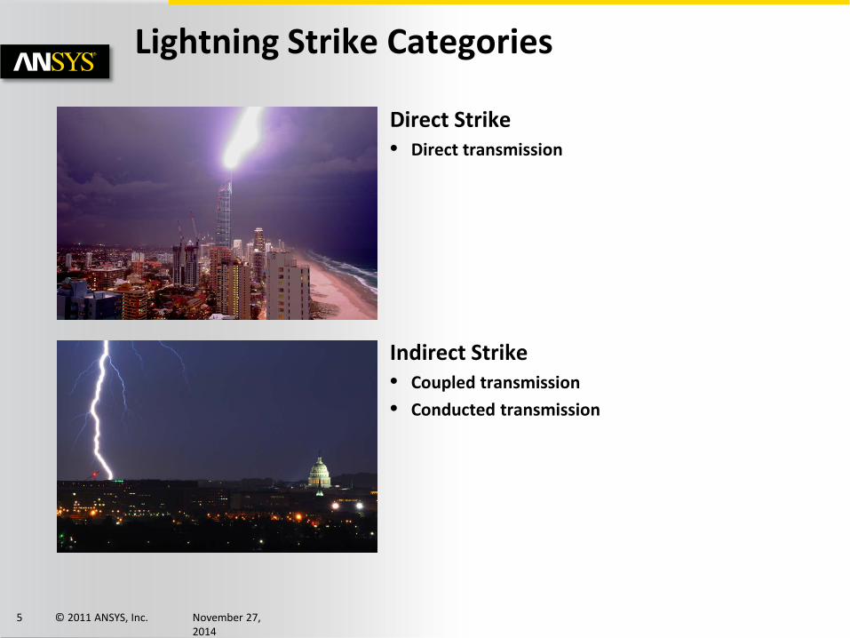
Direct Strike • Direct transmission
Indirect Strike • Coupled transmission • Conducted transmission
Lightning Strike Categories

© 2011 ANSYS, Inc. November 27, 2014
6
What is lightning… • Discharge of electricity resulting from terrestrially or atmospherically separated
charges.
Behaves like a massive current pulse.
Lightning Behavior

© 2011 ANSYS, Inc. November 27, 2014
7
Double exponential rise/fall characteristic
Lightning Characteristics
[ ] ( ) ( )( )ttm eeItI βα −− −=
Curr
ent [
A]
Time [s]
+
−+
=βα ss
II m11][L
fjs π2=Cu
rren
t [A
/Hz]
Frequency [Hz]
15kHz (-3dB)

© 2011 ANSYS, Inc. November 27, 2014
8
Multiple strikes of decreased magnitude are common • 4+ re-strikes of similar shape but smaller amplitude common. • Examples that follow look only at the first strike as it is always the most severe.
Lightning Characteristics

© 2011 ANSYS, Inc. November 27, 2014
9
Defense: 2.9/69 µs • MIL STD 464
Power Distribution: 1.2/50 µs • ANSI/IEEE C62.41
Telecommunications: 10/700 µs • TR-NWT-001089 • ITU K17-K20
Aeronautics: 6.4/69 µs • RTCA/DO-160, Section 22 • SAE/ARP5412
Lightning Waveform Standards
Decay to 50%
Rise from 10% to 90 %
Waveform time constants defined

© 2011 ANSYS, Inc. November 27, 2014
10
Waveform model parameter severity comes from averaged empirical data
Lightning Waveform Severity
>10kA >28kA >80kA >200kALightning 90% 50% 9.90% 0.10%
0%
20%
40%
60%
80%
100%
Lightning Magnitude Percentiles

© 2011 ANSYS, Inc. November 27, 2014
11
Agenda
• Industry Trends and Lightning Strikes
• Lightning Characterization
• ANSYS Simulation Approaches
• Examples
• Direct Strike : Tank and Aircraft
• Shielding
• Composite UAV Airframe
• Cabling
• Electromagnetic Pulse on a Tank

© 2011 ANSYS, Inc. November 27, 2014
12
3D Field Solvers • Time domain • Frequency domain
System Simulation • Parameter extraction • Circuit + 3D link
– Transient – System
ANSYS Simulation Methods
3D Field Solvers HFSS
• High Frequency FEM
Maxwell • Quasi-Static FEM
Q3D • Parameter Extraction
System Simulation Simplorer
• Multi-domain systems
Designer • Electronics, RF systems

© 2011 ANSYS, Inc. November 27, 2014
13
Simulation Methodology • Time Domain
– Direct waveform – Maximum time and time step are simulation parameters – Time steps must be solved sequentially
• Frequency Domain
– DFT waveform – Maximum frequency and frequency step are simulation
parameters – For linear problems impulse response can be obtained in highly
parallel fashion. – Alternative: Export a Reduced Order Model from HFSS Frequency
Domain with Full-Wave SPICE. Then simulate a coupled 3D + transient circuit with Designer or Simplorer
Measure current distribution and voltage levels at specific locations
ANSYS Simulation Methods
0 1 2 3 4 5
x 10-5
0
0.5
1
1.5
2x 10⁵
Time (s)
Cur
rent
(A)
Source Current
0 1 2 3 4 5 6 7 8
x 105
0
0.5
1
1.5
2
2.5
3x 10⁴
Frequency (Hz)
Cur
rent
(A)
Source Harmonics up to 125 of 400

© 2011 ANSYS, Inc. November 27, 2014
14
Frequency Methods (“By Hand”) • Fourier transform current input waveform • Calculate impulse response from 3D FEM
– Unit excitation as input across “all” frequencies in sweep • Convolve impulse response with input current • Inverse Fourier transform
Simulation Model
0 1 2 3 4 5
x 10-5
0
0.5
1
1.5
2
2.5x 10
5
time
curre
nt
0 5 10 15
x 104
0
0.5
1
1.5
2
2.5
3x 10
4
freq
curre
nt
X
0 5 10 15
x 104
0
0.2
0.4
0.6
0.8
freq
curre
nt
0 5 10 15
x 104
0
1
2
3
4
5
6x 10
6
freq
curre
nt
0 1 2 3 4 5
x 10-5
0
1
2
3
4
5
6x 10
4
time
curre
nt
=
F(ω) f (t)

© 2011 ANSYS, Inc. November 27, 2014
15
Lightning strike • Lightning enters through a bolt path • Lightning exits through ground contact • No material breakdown
Simulation Model
Lightning Entrance
Lightning Ground Exit

© 2011 ANSYS, Inc. November 27, 2014
16
Compare field values from time domain method to frequency domain method
Simulation Domain Comparison
0 1 2 3 4 5
x 10-5
0
0.5
1
1.5
2x 10⁵
Time (s)
Cur
rent
(A)
Source Current
Input Current
Colored- Time Domain Gray Dashed – Freq Domain
• 2.5MHz max frequency, • 5MHz sample frequency, • 6250Hz bandwidth
Output Currents Measure current through each leg
8” thick concrete, with rebar
7.2ft
6.5ft
1 2
3 4
0.00 10.00 20.00 30.00 40.00 50.00Time [us]
0.00
10000.00
20000.00
30000.00
40000.00
50000.00
60000.00
Cur
rent
[A]
No Frequency Dependence ANSOFT
Curve InfoTransient_J1
Setup1 : TransientTransient_J2
Setup1 : TransientTransient_J3
Setup1 : TransientTransient_J4
Setup1 : Transient
More evenly distributed. Peak down 10%.

© 2011 ANSYS, Inc. November 27, 2014
17
Agenda
• Industry Trends and Lightning Strikes
• Lightning Characterization
• ANSYS Simulation Approaches
• Examples
• Direct Strike : Tank and Aircraft
• Shielding
• Composite UAV Airframe
• Cabling
• Electromagnetic Pulse on a Tank

© 2011 ANSYS, Inc. November 27, 2014
18
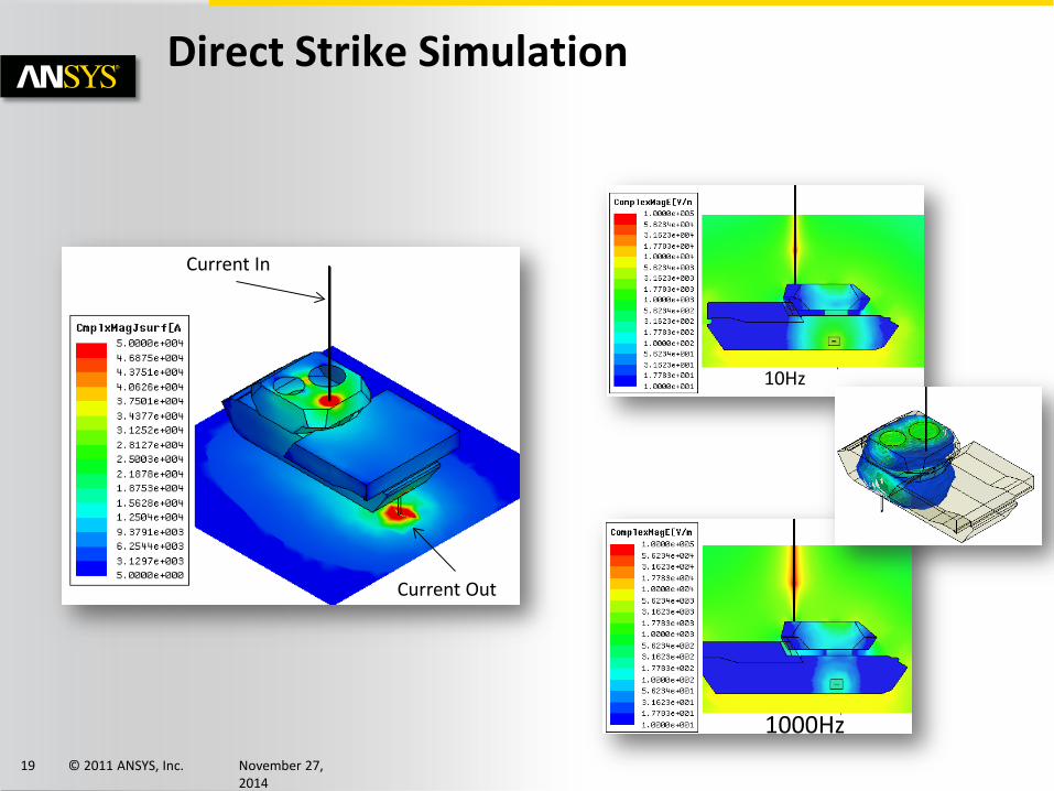
Tank: Identify surface current densities and field strength inside
Direct Strike Simulation
Lightning strike
Increased current density along edges
T=4uS
DC
© 2011 ANSYS, Inc. November 27, 2014
19
Direct Strike Simulation
10Hz
1000Hz
Current In
Current Out

© 2011 ANSYS, Inc. November 27, 2014
20
Building with water infiltration (4S/m)
Direct Strike Simulation
no water
1ft water
Electric current flows into the flooded space from the structure
Current animation
Current animation
0 0.2 0.4 0.6 0.8 1x 10⁻⁴
0
500
1000
1500
Time (s)C
urre
nt (A
)
Current Into Water
Without water, skin effect and low impedance rebar keeps current out of the habited area
With flooding significant current enters the habited area

© 2011 ANSYS, Inc. November 27, 2014
21
Aircraft - Direct Strike
HFSS: Aircraft direct strike

© 2011 ANSYS, Inc. November 27, 2014
22
Agenda
• Industry Trends and Lightning Strikes
• Lightning Characterization
• ANSYS Simulation Approaches
• Examples
• Direct Strike : Tank and Aircraft
• Shielding
• Composite UAV Airframe
• Cabling
• Electromagnetic Pulse on a Tank

© 2011 ANSYS, Inc. November 27, 2014
23
Aircraft Outer Shell • Typically made of aluminum or carbon fiber • What is the expected frequency dependent shielding provided by each for a 3mm
material thickness?
Shielding Effectiveness
Material Conductivity [S/m] Thickness Frequency below which fields penetrate
with minimal attenuation*
Aluminum 3.8e7 3mm 10Hz
Carbon Fiber 6.7e4 3mm 1KHz

© 2011 ANSYS, Inc. November 27, 2014
24
Boundary Conditions • Use empty PerfE/PerfH tube with voltage source
as reference. Expect full transmission.
Shielding Test • Can 2D boundary yield the same results vs
frequency as 3D Shell?
Shielding Test
Side Walls PerfH Top/Bottom are PerfE
Voltage Source
Polyline down center to measure E and H field values
Far end is radiation boundary
© 2011 ANSYS, Inc. November 27, 2014
25
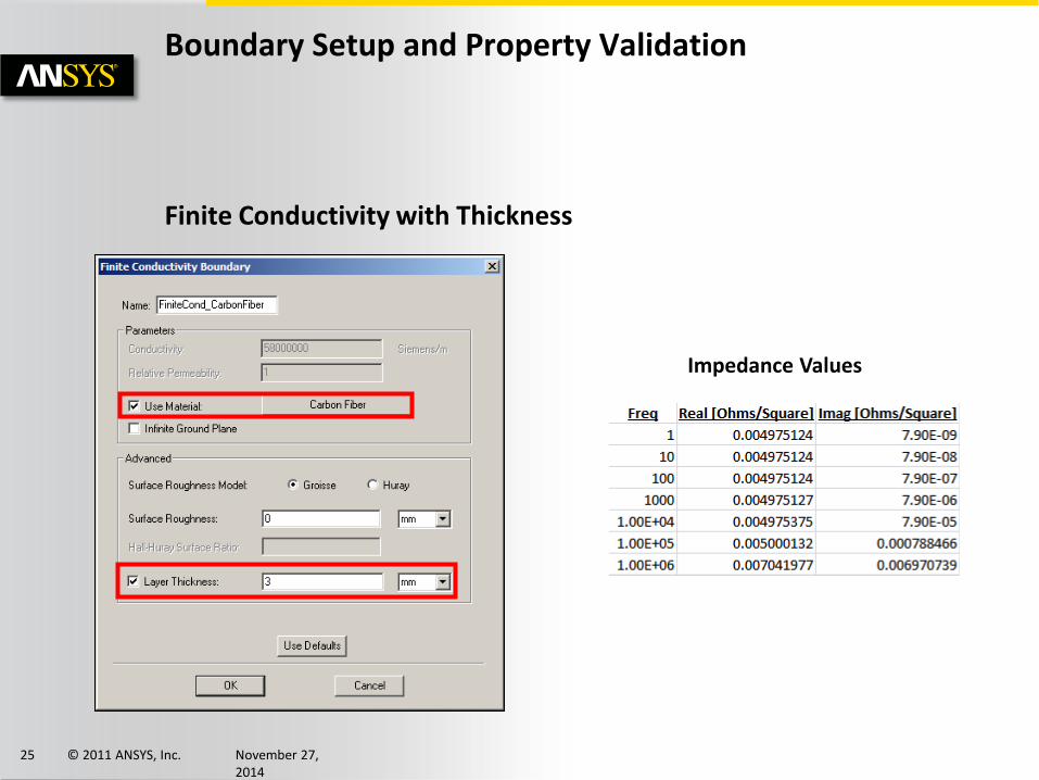
Finite Conductivity with Thickness
Boundary Setup and Property Validation
Impedance Values

© 2011 ANSYS, Inc. November 27, 2014
26
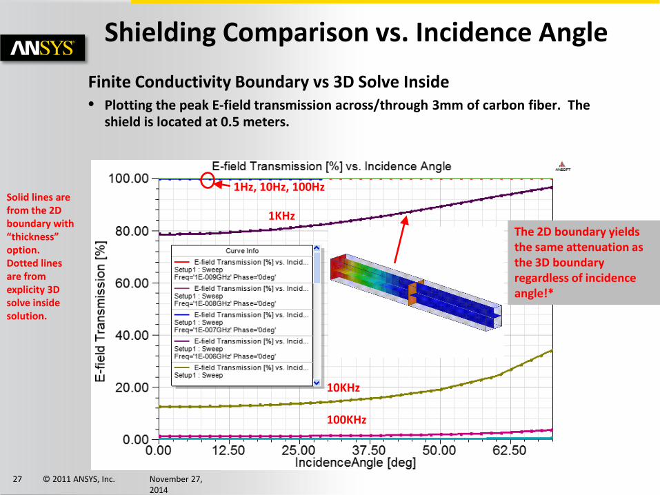
Finite Conductivity Boundary vs 3D Solve Inside • Plotting the peak electric field along a polyline across/through 3mm of carbon
fiber. The shield is located at 0.5 meters.
PeakE vs. Distance and Frequency
Solid lines are from the 2D boundary with “thickness” option. Dotted lines are from explicitly 3D solve inside solution.
1Hz, 10Hz, 100Hz
1KHz
10KHz
100KHz
The 2D boundary yields the same attenuation as the 3D boundary for boresight energy incidence!
© 2011 ANSYS, Inc. November 27, 2014
27
Finite Conductivity Boundary vs 3D Solve Inside • Plotting the peak E-field transmission across/through 3mm of carbon fiber. The
shield is located at 0.5 meters.
Shielding Comparison vs. Incidence Angle
Solid lines are from the 2D boundary with “thickness” option. Dotted lines are from explicity 3D solve inside solution.
The 2D boundary yields the same attenuation as the 3D boundary regardless of incidence angle!*
1Hz, 10Hz, 100Hz
1KHz
10KHz
100KHz

© 2011 ANSYS, Inc. November 27, 2014
28
Summary • 2D finite conductivity boundaries with the “thickness” option provide can
effectively be used to calculate transmission through carbon fiber or metallic shells. • The 2D boundary approximation has been shown to compare well with a 3D solve
inside metal at lightning frequencies, but with much greater solution efficiency!
Shielding Test Conclusions

© 2011 ANSYS, Inc. November 27, 2014
29
Agenda
• Industry Trends and Lightning Strikes
• Lightning Characterization
• ANSYS Simulation Approaches
• Examples
• Direct Strike : Tank and Aircraft
• Shielding
• Composite UAV Airframe
• Cabling
• Electromagnetic Pulse on a Tank

© 2011 ANSYS, Inc. November 27, 2014
30
Predator UAV with Carbon Fiber Shell
Strike at wingtip
Exit at tail PeakH at 1Hz Penetrates the wings and fuselage

© 2011 ANSYS, Inc. November 27, 2014
31
H-field on Cut Planes Inside the Predator
H-Field vs Frequency Filled at low frequencies, and H-field repelled at higher frequencies

© 2011 ANSYS, Inc. November 27, 2014
32
Agenda
• Industry Trends and Lightning Strikes
• Lightning Characterization
• ANSYS Simulation Approaches
• Examples
• Direct Strike : Tank and Aircraft
• Shielding
• Composite UAV Airframe
• Cabling
• Electromagnetic Pulse on a Tank

© 2011 ANSYS, Inc. November 27, 2014
33
A320 with Cables in the Wing and Fuselage
Orange/yellow color in fuselage is at 1Hz. Blue color in fuselage is at 1MHz.

© 2011 ANSYS, Inc. November 27, 2014
34
A320 with Cables in the Wing and Fuselage
Two single strand cables inside fuselage. A four conductor cable in the wing.

© 2011 ANSYS, Inc. November 27, 2014
35
Current along A320 Cables
Current flowing on cables, here at 1MHz
Plot PeakH vs. distance along the whole cable length for each frequency.

© 2011 ANSYS, Inc. November 27, 2014
36
Multiphysics and Lighting Strikes
ANSYS HFSS Simulation of Lightning Strike ANSYS Mechanical – Transient Thermal
Mapped Heat Flux

© 2011 ANSYS, Inc. November 27, 2014
37
ANSYS Workbench

© 2011 ANSYS, Inc. November 27, 2014
38
ANSYS Mechanical - Transient Thermal
Apply HFSS Heat Flux until t1
Deactivate Heat Flux after t1
HFSS - Heat Flux
Transient Thermal - Temperature

© 2011 ANSYS, Inc. November 27, 2014
39
Agenda
• Industry Trends and Lightning Strikes
• Lightning Characterization
• ANSYS Simulation Approaches
• Examples
• Direct Strike : Tank and Aircraft
• Shielding
• Composite UAV Airframe
• Cabling
• Electromagnetic Pulse on a Tank

© 2011 ANSYS, Inc. November 27, 2014
40
Electromagnetic Pulse
EMP
EMP explosive device in background

© 2011 ANSYS, Inc. November 27, 2014
41
Fourier Transform
Peak 50 kV/m Rise time ~3ns
( )4 7 6 8( ) 6.5 4 e t e ty t e e e− ⋅ − ⋅= ⋅ − ( )( )2 4 7 2 6 83.64 13( )
j f e j f eeY f
π π⋅ + ⋅ +=
High Altitude EMP Signal

© 2011 ANSYS, Inc. November 27, 2014
42
103MHz
146MHz
Different scale (not shown)
Sensitive microstrip line on board inside tank
Tank Resonance Results

© 2011 ANSYS, Inc. November 27, 2014
43
p1:1p1_45:1
p2_45:1
PNUM=1
RZ=50ohmIZ=0ohm
PNUM=2
IZ=0ohm
PNUM=3RZ=50ohm
V
Name=Vout
V Nam
e=Vi
n
0
10000
20000
30000
40000
50000
60000
0.0E+00 5.0E-08 1.0E-07 1.5E-07 2.0E-07 2.5E-07
EMP Excitation
Input Pulse
What’s the EMP effect on the output signal?
Microstrip on board inside tank.
EMP and Electronics Interaction
© 2011 ANSYS, Inc. November 27, 2014
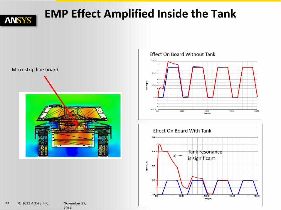
44
Microstrip line board
Effect On Board Without Tank
Effect On Board With Tank
Tank resonance is significant
EMP Effect Amplified Inside the Tank