AeroMACS Verification Plan & Report - Phase 2
159
AeroMACS Verification Plan & Report - Phase 2 Document information Project Title Airport Surface Datalink Project Number 15.02.07 Project Manager INDRA Deliverable Name AeroMACS Verification Plan & Report - Phase 2 Deliverable ID D10 Edition 00.00.07 Template Version 03.00.00 Task contributors THALES; DSNA ; SELEX ES; INDRA; EUROCONTROL; AIRBUS; Abstract The general purpose of the 15.02.07 is to verify the AeroMACS Data Link. This document describes the verification plan applied within the 15.02.07 Project for phase 2 testing and the corresponding tests report. AeroMACS phase 2 integration and testing activities includes: • Laboratory tests, • Toulouse airport tests.
Transcript of AeroMACS Verification Plan & Report - Phase 2

AeroMACS Verification Plan & Report - Phase 2
Document information
Project Title Airport Surface Datalink
Project Number 15.02.07
Project Manager INDRA
Deliverable Name AeroMACS Verification Plan & Report - Phase 2
Deliverable ID D10
Edition 00.00.07
Template Version 03.00.00
Task contributors
THALES; DSNA ; SELEX ES; INDRA; EUROCONTROL; AIRBUS;
Abstract
The general purpose of the 15.02.07 is to verify the AeroMACS Data Link. This
document describes the verification plan applied within the 15.02.07 Project for phase
2 testing and the corresponding tests report.
AeroMACS phase 2 integration and testing activities includes:
• Laboratory tests,
• Toulouse airport tests.

Disclaimer
The contents presented in this document are for informative purposes only.
The P15.02.07 Members grant permission to ICAO ACP WGS to consult this document for information only without any right to resell or redistribute them or to compile or create derivative works therefrom, except for supporting the validation of the AeroMACS SARPs.
This document has been developed by AENA, AIRBUS, DSNA, EUROCONTROL, INDRA, NATMIG, SELEX and THALES for the SESAR Joint Undertaking within the frame of the SESAR Programme co-financed by the European Union and EUROCONTROL.
The opinions expressed herein reflect the author’s view only. It is provided “as is”, without warranty of any kind, either express or implied, including, without limitation, warranties of merchantability, fitness for a particular purpose and non-infringement. The SJU does not, in particular, make any warranties or representations as to the accuracy or completeness of this document which has not yet been formally assessed or approved in the framework of the SESAR Programme. Therefore, this document after review of the SJU may change, improve, be updated or replaced by another version without notice.
Under no circumstances shall the SESAR Joint Undertaking and the P.15.02.07 Members be liable for any loss, damage, liability or expense incurred or suffered that is claimed to have resulted from the use of any of the information included herein including, without limitation, any fault, error, omission, interruption or delay with respect thereto. The use of this document is at the ICAO ACP WGS sole risk.
Any reproduction or use of this document other than the ones defined above requires the prior written approval of the P15.02.07 Members, author(s) of this document

Project Number 15.02.07 Edition 00.00.07 D10 - AeroMACS Verification Plan & Report - Phase 2
2 of 158
©SESAR JOINT UNDERTAKING, 2014. Created by AENA, AIRBUS, DSNA, EUROCONTROL, INDRA, NATMIG, SELEX ES
and THALES for the SESAR Joint Undertaking within the frame of the SESAR Programme co-financed by the EU and EUROCONTROL. Reprint with approval of publisher and the source properly acknowledged.
Authoring & Approval
Prepared By - Authors of the document.
Name & Company Position & Title Date
Philippe Charpentier / THALES Task leader 25/09/2014
Giulio Vivaldi / SELEX ES Project Contributor 25/09/2014
Marc Lehmann / DSNA Project Contributor 25/09/2014
Pierre Cluzeaud / THALES Project Contributor 25/09/2014
Jean-Marc Bazin / THALES Project Contributor 25/09/2014
Simona Pierattelli / SELEX ES Project Contributor 25/09/2014
Fabrizio Faggi / SELEX ES Project Contributor 25/09/2014
Reviewed By - Reviewers internal to the project.
Name & Company Position & Title Date
Hyung-Woo Kim / INDRA Project Manager 25/09/2014
Nikos Fistas / EUROCONTROL Project Member 25/09/2014
Stéphane Tamalet / AIRBUS Project Member 25/09/2014
Aurora Sanchez Barro / AENA Project Member 25/09/2014
Reviewed By - Other SESAR projects, Airspace Users, staff association, military, Industrial Support, other organisations.
Name & Company Position & Title Date
Domenico Cardamone / SELEX ES P09.16 Contributor 25/09/2014
Approved for submission to the SJU By – Representatives of the company involved in the project.
Name & Company Position & Title Date
Project Number 15.02.07 Edition 00.00.07 D10 - AeroMACS Verification Plan & Report - Phase 2
3 of 158
©SESAR JOINT UNDERTAKING, 2014. Created by AENA, AIRBUS, DSNA, EUROCONTROL, INDRA, NATMIG, SELEX ES
and THALES for the SESAR Joint Undertaking within the frame of the SESAR Programme co-financed by the EU and EUROCONTROL. Reprint with approval of publisher and the source properly acknowledged.
Document History
Edition Date Status Author Justification
00.00.01 17/01/2014 DRAFT THALES New document based on VP & VR template
00.00.02 27/06/2014 DRAFT THALES
Document with Thales lab and Airport tests results for partner review
00.00.03 15/07/2014 DRAFT SELEX Added Selex test cases and test results for partner review
00.00.04 20/08/2014 DRAFT THALES Changes following document review by partners
00.00.05 04/09/2014 DRAFT SELEX
Changes following document review by partners. Added information on IOT tests. Errors fixing, editorial changes.
00.00.06 25/09/2014 DRAFT THALES Integration of changes following last comments.
00.00.07 10/10/2014 DRAFT THALES Additional comments from joint SESAR P15.2.7/P9.16 meeting addressed

Project Number 15.02.07 Edition 00.00.07 D10 - AeroMACS Verification Plan & Report - Phase 2
4 of 158
©SESAR JOINT UNDERTAKING, 2014. Created by AENA, AIRBUS, DSNA, EUROCONTROL, INDRA, NATMIG, SELEX ES
and THALES for the SESAR Joint Undertaking within the frame of the SESAR Programme co-financed by the EU and EUROCONTROL. Reprint with approval of publisher and the source properly acknowledged.
Table of Contents
TABLE OF CONTENTS ..................................................................................................................................... 4
LIST OF TABLES ................................................................................................................................................ 6
LIST OF FIGURES .............................................................................................................................................. 6
EXECUTIVE SUMMARY .................................................................................................................................... 8
1 INTRODUCTION .......................................................................................................................................... 9
1.1 PURPOSE OF THE DOCUMENT ............................................................................................................... 9 1.2 INTENDED READERSHIP......................................................................................................................... 9 1.3 STRUCTURE OF THE DOCUMENT ........................................................................................................... 9 1.4 GLOSSARY OF TERMS ......................................................................................................................... 10 1.5 ACRONYMS AND TERMINOLOGY ......................................................................................................... 10
2 CONTEXT OF THE VERIFICATION ...................................................................................................... 12
3 VERIFICATION APPROACH .................................................................................................................. 13
3.1 VERIFICATION OVERVIEW ................................................................................................................... 13 3.2 VERIFICATION PLAN............................................................................................................................. 13 3.3 VERIFICATION ASSUMPTIONS ............................................................................................................. 13 3.4 VERIFICATION REQUIREMENTS ........................................................................................................... 14 3.5 INTEGRATION AND PRELIMINARY VERIFICATION ACTIVITIES ............................................................... 14
3.5.1 Introduction ................................................................................................................................... 14 3.5.2 Lab testing ..................................................................................................................................... 14 3.5.3 Airport testing ................................................................................................................................ 17
3.6 ACCEPTANCE CRITERIA ....................................................................................................................... 31
4 VERIFICATION ACTIVITIES ................................................................................................................... 32
4.1 VERIFICATION EXERCISES LIST .......................................................................................................... 32 4.1.1 Thales lab and airport test cases identification ........................................................................ 32 4.1.2 Selex lab test cases identification .............................................................................................. 34
4.2 VERIFICATION ACTIVITIES MASTER SCHEDULE ................................................................................... 35
5 VERIFICATION EXERCISES RESULTS ............................................................................................... 36
5.1 SUMMARY OF VERIFICATION EXERCISES RESULTS ........................................................................... 36 5.2 ANALYSIS OF VERIFICATION EXERCISES RESULTS ............................................................................ 37
6 CONCLUSIONS AND RECOMMENDATIONS .................................................................................... 38
7 REFERENCES ........................................................................................................................................... 39
7.1 REFERENCE DOCUMENTS .................................................................................................................. 39
APPENDIX A PHASE 2 VERIFICATION EXERCISES AND RESULTS ............................................ 40
A.1 SELEX LAB VERIFICATION EXERCISES ................................................................................................. 41 A.1.1 Verification Exercise # P2_LAB1_1 Connection Re-Establishment ..................................... 41 A.1.2 Verification Exercise # P2_LAB1_2 Power Control ................................................................ 47 A.1.3 Verification Exercise # P2_LAB1_3 Quality of Service .......................................................... 54 A.1.4 Verification Exercise # P2_LAB1_4 Security ........................................................................... 64 A.1.5 Verification Exercise # P2_LAB1_5 Radio Characteristic Requirements ............................ 70 A.1.6 Verification Exercise # P2_LAB1_6 Limited IOT Requirements ........................................... 74
A.2 THALES LAB VERIFICATION EXERCISES ............................................................................................... 83 A.2.1 Verification Exercise # TLAB2_010 ........................................................................................... 83 A.2.2 Verification Exercise # TLAB2_020 ........................................................................................... 86 A.2.3 Verification Exercise # TLAB2_030 ........................................................................................... 94 A.2.4 Verification Exercise # TLAB2_040 ........................................................................................... 97
A.3 THALES TOULOUSE AIRPORT VERIFICATION EXERCISES .................................................................... 99 A.3.1 Introduction ................................................................................................................................... 99 A.3.2 Verification Exercise # TAIR_010 ............................................................................................ 102

Project Number 15.02.07 Edition 00.00.07 D10 - AeroMACS Verification Plan & Report - Phase 2
5 of 158
©SESAR JOINT UNDERTAKING, 2014. Created by AENA, AIRBUS, DSNA, EUROCONTROL, INDRA, NATMIG, SELEX ES
and THALES for the SESAR Joint Undertaking within the frame of the SESAR Programme co-financed by the EU and EUROCONTROL. Reprint with approval of publisher and the source properly acknowledged.
A.3.3 Verification Exercise # TAIR_020 ............................................................................................ 117 A.3.4 Verification Exercise # TAIR_030 ............................................................................................ 128 A.3.5 Verification Exercise # TAIR_040 ............................................................................................ 145 A.3.6 Verification Exercise # TAIR_050 ............................................................................................ 151

Project Number 15.02.07 Edition 00.00.07 D10 - AeroMACS Verification Plan & Report - Phase 2
6 of 158
©SESAR JOINT UNDERTAKING, 2014. Created by AENA, AIRBUS, DSNA, EUROCONTROL, INDRA, NATMIG, SELEX ES
and THALES for the SESAR Joint Undertaking within the frame of the SESAR Programme co-financed by the EU and EUROCONTROL. Reprint with approval of publisher and the source properly acknowledged.
List of tables
Table 1: Testing organization ................................................................................................................ 13 Table 2: Phase 2 lab verification objectives summary .......................................................................... 16 Table 3: Airport dedicated frequencies for testing ................................................................................ 18 Table 4: VO summary ........................................................................................................................... 26 Table 5: identification of Phase 2 Thales lab test cases ....................................................................... 32 Table 6: Identification of Thales/DSNA Toulouse airport test cases .................................................... 33 Table 7: identification of Phase 2 Selex lab test cases ......................................................................... 34 Table 8: Summary of Thales lab tests results for phase 2 .................................................................... 36 Table 9: Summary of Selex Lab. tests results for phase 2 ................................................................... 36 Table 10: Summary of Thales/DSNA Airport tests results .................................................................... 37 Table 11: Service Flows characteristics ................................................................................................ 59
List of figures
Figure 3-1 : Lab_test_bed_01 (THALES) ............................................................................................. 15 Figure 3-2 : Lab_test_bed_02 (SELEX) ................................................................................................ 15 Figure 3-3 : Thales-DSNA airport ground test configuration ................................................................. 18 Figure 3-4 : Airport installation .............................................................................................................. 19 Figure 3-5: General view of the former control tower ........................................................................... 20 Figure 3-6: GS location ......................................................................................................................... 20 Figure 3-7: Roof situation on the left – Working position on the right ................................................... 21 Figure 3-8: Ground station mechanical interface .................................................................................. 21 Figure 3-9: Calculated coverage of the two GS (best server zone) ...................................................... 22 Figure 3-10: Overlapping zone between GS1 and GS2 ....................................................................... 23 Figure 3-11: fix MS location .................................................................................................................. 24 Figure 3-12: MS fix location .................................................................................................................. 24 Figure 3-13: MS setup ........................................................................................................................... 25 Figure 3-14: Setup of MS in the vehicles .............................................................................................. 25 Figure 3-15: Items integrated in the vehicles ........................................................................................ 25 Figure 3-16: Test location in Toulouse Airport ..................................................................................... 30 Figure 4-1 : 15.02.07 Verification Activities ........................................................................................... 35 Figure 4-2 : Integration and Testing Phase 2 schedule ........................................................................ 35 Figure 7-1: MS Log - Initial Net Entry: MS Registration ........................................................................ 44 Figure 7-2: Forced Link Loss and Network Exit .................................................................................... 45 Figure 7-3: Network Re-entry ................................................................................................................ 46 Figure 7-4: BS Log - CQICH Allocation ................................................................................................ 51 Figure 7-5: CQICH measurements ....................................................................................................... 52 Figure 7-6: CL PC - initial situation ....................................................................................................... 53 Figure 7-7: CL PC - Final situation ........................................................................................................ 54 Figure 7-8: IPERF Log - 2 SFs with the same priority but different MSTR ........................................... 60 Figure 7-9: UL - throughput on SF1 ...................................................................................................... 61 Figure 7-10: UL - throughput on SF2 .................................................................................................... 62 Figure 7-11: SF2 with higher priority ..................................................................................................... 63 Figure 7-12: Cipher Suites supported by MS ........................................................................................ 67 Figure 7-13: "Server Hello" from ASN-GW ........................................................................................... 68 Figure 7-14: Privacy Key Management Protocol .................................................................................. 69 Figure 7-15: First cyphered messages after Authentication: DHCP ..................................................... 70 Figure 7-16: Frequency filter at 5113.5 MHz ........................................................................................ 73 Figure 7-17: Net Entry - Pre-attachment ............................................................................................... 78 Figure 7-18: Authentication - MS Identity Acceptance .......................................................................... 79 Figure 7-19: Authentication – Certificates exchange ............................................................................ 80 Figure 7-20: Authentication – Net Exit .................................................................................................. 81 Figure 7-21: TLAB2_010 iperf screenshot ............................................................................................ 84 Figure 7-22: test bed configuration with a signal generator .................................................................. 86 Figure 7-23: Selex MS in Thales lab (Baseband 1U rack below and RF 1U rack above) .................... 97

Project Number 15.02.07 Edition 00.00.07 D10 - AeroMACS Verification Plan & Report - Phase 2
7 of 158
©SESAR JOINT UNDERTAKING, 2014. Created by AENA, AIRBUS, DSNA, EUROCONTROL, INDRA, NATMIG, SELEX ES
and THALES for the SESAR Joint Undertaking within the frame of the SESAR Programme co-financed by the EU and EUROCONTROL. Reprint with approval of publisher and the source properly acknowledged.
Figure 7-24: Detailed Airport schedule ................................................................................................. 99 Figure 7-25: Training for Airport Clearance and test plan preparation (TAIR_10 up to TAIR_50) ..... 100 Figure 7-26: Setup of the BS on a tower and MS on a truck for outdoor tests ................................... 100 Figure 7-27: Outdoor tests in gennevilliers premises in NLOS ........................................................... 101 Figure 7-28: Outdoor tests in Gennevilliers @ 80 km/h ...................................................................... 101 Figure 7-29: The former control tower with the 2 Thales BS .............................................................. 105 Figure 7-30: BS orientation and operator position .............................................................................. 106 Figure 7-31: MS1 at "PB" fix location (+ two equipped vehicles with MS2 and MS3) ........................ 106 Figure 7-32: 2 DGAC Vehicle installation with 2 Thales MS ............................................................... 107 Figure 7-33: BS1 Airport measured coverage (BS 2 off) .................................................................... 108 Figure 7-34: Thales BS1 coverage calculation ................................................................................... 109 Figure 7-35: Thales BS2 Airport measured coverage (BS1 off) ........................................................ 110 Figure 7-36: Thales BS2 coverage calculation ................................................................................... 111 Figure 7-37: MLS (south) test location ................................................................................................ 112 Figure 7-38: MLS (south & north) interference zone with 70dB rejection (source D04) ..................... 113 Figure 7-39: MLS tests location .......................................................................................................... 113 Figure 7-40: Close analyse in the vicinity of MLS ............................................................................... 114 Figure 7-41: Spectrum measurement near MLS signal (south) .......................................................... 114 Figure 7-42: Spectrum measurements near MLS signal (north) ......................................................... 115 Figure 7-43: Mask due to aircraft which hide the antenna on PB ....................................................... 116 Figure 7-44: THALES BS1 coverage measurements versus simulation ............................................ 124 Figure 7-45: BS2 coverage measurements versus coverage simulation ........................................... 127 Figure 7-46: Recordings on the Fly of the RSSI in NLOS conditions ................................................. 133 Figure 7-47: NLOS point #1 measurement details ............................................................................. 134 Figure 7-48: NLOS point #3 measurement details ............................................................................. 135 Figure 7-49: NLOS point #7 measurement details ............................................................................. 136 Figure 7-50: NLOS point #9 measurement details ............................................................................. 137 Figure 7-51: NLOS point #11 measurement details ........................................................................... 138 Figure 7-52: NLOS point #13 measurement details ........................................................................... 139 Figure 7-53: NLOS point #15 measurement details ........................................................................... 140 Figure 7-54: NLOS point #18 measurement details ........................................................................... 141 Figure 7-55: NLOS point #19 measurement details ........................................................................... 142 Figure 7-56: Measurements on the outside of the Airport .................................................................. 143 Figure 7-57: Simulated field strength near the terminal ...................................................................... 144 Figure 7-58: Mobility test location (ATE -> Taxiway W 100 to W 60 – round trip) .............................. 147 Figure 7-59: Priority to the Aircrafts traffic on the taxiway .................................................................. 147 Figure 7-60: recorded RSSI of mobility test at 50 km/h ...................................................................... 148 Figure 7-61: recorded RSSI of mobility test at 90 km/h ...................................................................... 149 Figure 7-62: recorded RSSI of mobility test at 120 km/h .................................................................... 150 Figure 7-63: THALES BS1 / BS2 best server map ............................................................................. 151 Figure 7-64: The two MS at point 7 ..................................................................................................... 154 Figure 7-65: 3 MS at PB ...................................................................................................................... 154 Figure 7-66: Alternate channels - BS1 measurements ....................................................................... 155 Figure 7-67: Adjacent channels - BS1 measurements ....................................................................... 155 Figure 7-68: Alternate channels - BS2 measurements ....................................................................... 156 Figure 7-69: Adjacent channels - BS2 measurements ....................................................................... 156

Project Number 15.02.07 Edition 00.00.07 D10 - AeroMACS Verification Plan & Report - Phase 2
8 of 158
©SESAR JOINT UNDERTAKING, 2014. Created by AENA, AIRBUS, DSNA, EUROCONTROL, INDRA, NATMIG, SELEX ES
and THALES for the SESAR Joint Undertaking within the frame of the SESAR Programme co-financed by the EU and EUROCONTROL. Reprint with approval of publisher and the source properly acknowledged.
Executive summary
The goal of project 15.02.07, in strong collaboration with Project 9.16, is to define, validate and demonstrate the technical standard based upon existing IEEE 802.16e of the future airport surface data link as foreseen by the aviation community and ICAO. Therefore, it includes the modification of the IEEE 802.16e standard and the developing of a new AeroMACS profile dedicated for airport surface datalink for ATC / AOC services, in order to be compliant with SESAR / ICAO FCI recommendations.
The mentioned evaluation assessed the performance and capacity of the technology by means of analytical work and simulations in order to develop design specifications. Moreover, prototypes were defined and developed to demonstrate results through measurements and trials, in a strong coordination with the appropriate standardisation bodies.
Therefore, 9.16 and 15.02.07 projects are contributing to the development of an aviation technical standard to be recognised by ICAO in direct and strong cooperation with Eurocae WG82 and RTCA SC 223.
The purpose of the present document is to establish project 15.02.07 “Verification plan and report” corresponding to the “Verification Objectives” described in document D05.2. (cf. [1]) and identified for phase 2 test campaigns.

Project Number 15.02.07 Edition 00.00.07 D10 - AeroMACS Verification Plan & Report - Phase 2
9 of 158
©SESAR JOINT UNDERTAKING, 2014. Created by AENA, AIRBUS, DSNA, EUROCONTROL, INDRA, NATMIG, SELEX ES
and THALES for the SESAR Joint Undertaking within the frame of the SESAR Programme co-financed by the EU and EUROCONTROL. Reprint with approval of publisher and the source properly acknowledged.
1 Introduction
1.1 Purpose of the document The purpose of the Verification Plan & Report is to describe the phase 2 verification test cases and to gather corresponding test results achieved within the 15.02.07 project in order to assess the AeroMACS Data Link thanks to the use of Mobile Stations (MS) mock-ups and Ground Stations (GS) prototypes.
Verification test cases are derived from the Verification Objectives (VO) defined in the D05.2 document (see [1]). They cover following aspects:
MS/BS Interoperability, including AeroMACS Profile,
RF specification and performances,
RF performances in real environments. Within the 15.02.07 project, verification tests consist in:
Laboratory tests, held in SELEX and THALES premises, with both partners pieces of equipment,
Field tests, held in Toulouse Airport, by THALES & DSNA. The 15.02.07 Verification Activity has been divided in two separate Working Activities described in the D05.2 document (see [1]):
Phase 1 is related to Laboratory Tests that verify the main part of the MS/BS Interoperability and RF performances objectives. This was completed through task T06 in 2013 and concluded by deliverable D06.
Phase 2 is related both to Laboratory Tests and Toulouse Airport Tests. They are reported in present D10 document. Indeed, this document is the deliverable related to P15.02.07. “integration & testing - phase 2”, supported by tasks T010 and T011.
1.2 Intended readership This document is intended to be used primarily by the partners of the 15.02.07 Project. However, for coordination reasons, also Projects SESAR 9.16, SANDRA SP6 and SANDRA SP7 could take this deliverable into account. The document is also useful for standardization groups, and in particular for AeroMACS SARPS validation. Other operational/system projects could make use of the deliverables of 15.02.07/9.16 projects.
1.3 Structure of the document
The structure of the document is based on 7 chapters and appendix:
- Chapter 1 is an introduction describing the purpose of the document and the intended readership.
- Chapter 2 describes the context of the Verification.
- Chapter 3 defines the verification approach, describing how the verification scenarios will be implemented in the various test locations (Manufacturers Laboratories, Toulouse Airports).
- Chapter 4 details verification activities and means
- Chapter 5 gives a summary of the test results
- Chapter 6 consists of the conclusion and recommendations
- Chapter 7 lists the reference documents
Project Number 15.02.07 Edition 00.00.07 D10 - AeroMACS Verification Plan & Report - Phase 2
10 of 158
©SESAR JOINT UNDERTAKING, 2014. Created by AENA, AIRBUS, DSNA, EUROCONTROL, INDRA, NATMIG, SELEX ES
and THALES for the SESAR Joint Undertaking within the frame of the SESAR Programme co-financed by the EU and EUROCONTROL. Reprint with approval of publisher and the source properly acknowledged.
- Appendix A gives the tests cases related to the verification objectives of the SESAR 15.02.07 project for phase 2 and the detailed tests results.
This document structure maps both SJU VP and VR templates.
1.4 Glossary of terms
For terminology clarification, the following terms are defined below:
- “Mock-up” : Part of MS test equipment
- “Prototype” : Base/Mobile station prototype equipment
- “System test platform”: Bring together several prototypes, mock-up and tools
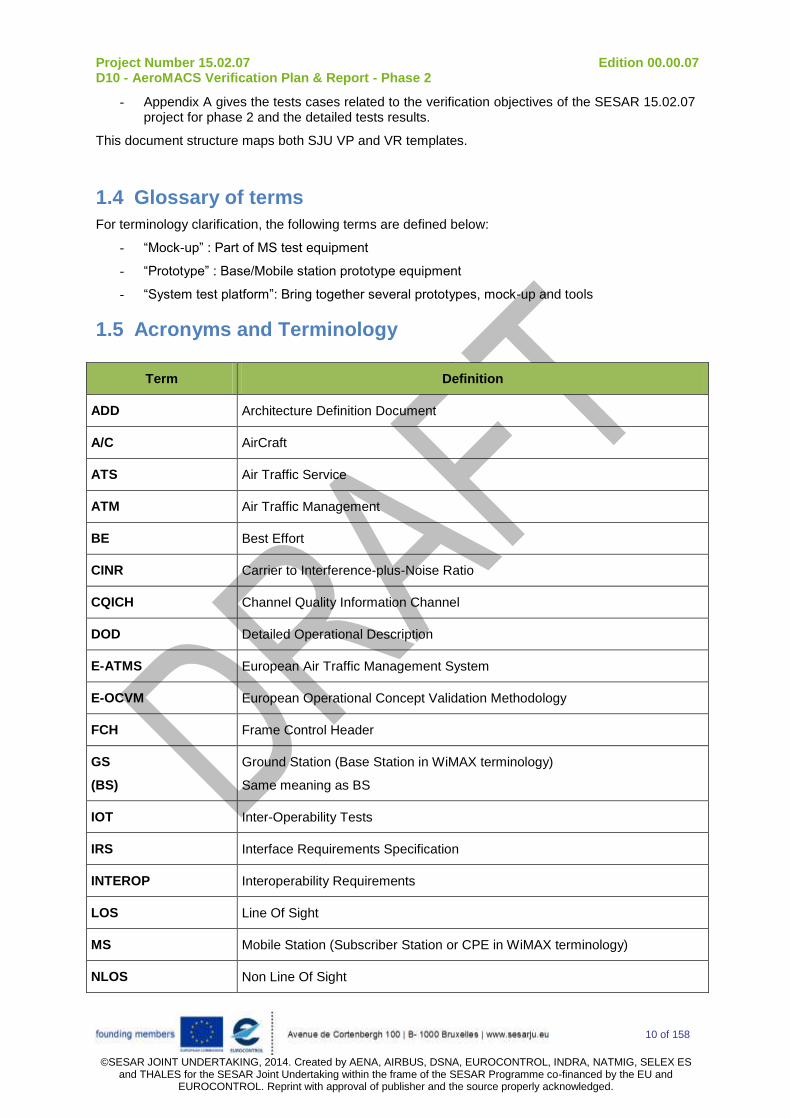
1.5 Acronyms and Terminology
Term Definition
ADD Architecture Definition Document
A/C AirCraft
ATS Air Traffic Service
ATM Air Traffic Management
BE Best Effort
CINR Carrier to Interference-plus-Noise Ratio
CQICH Channel Quality Information Channel
DOD Detailed Operational Description
E-ATMS European Air Traffic Management System
E-OCVM European Operational Concept Validation Methodology
FCH Frame Control Header
GS
(BS)
Ground Station (Base Station in WiMAX terminology)
Same meaning as BS
IOT Inter-Operability Tests
IRS Interface Requirements Specification
INTEROP Interoperability Requirements
LOS Line Of Sight
MS Mobile Station (Subscriber Station or CPE in WiMAX terminology)
NLOS Non Line Of Sight

Project Number 15.02.07 Edition 00.00.07 D10 - AeroMACS Verification Plan & Report - Phase 2
11 of 158
©SESAR JOINT UNDERTAKING, 2014. Created by AENA, AIRBUS, DSNA, EUROCONTROL, INDRA, NATMIG, SELEX ES
and THALES for the SESAR Joint Undertaking within the frame of the SESAR Programme co-financed by the EU and EUROCONTROL. Reprint with approval of publisher and the source properly acknowledged.
Term Definition
nLOS Near Line Of Sight
nRTPS Non-Real-Time Polling Service
OFA Operational Focus Areas
OSED Operational Service and Environment Definition
PCO Point of COntrol
QOS Quality Of Service
RSSI Received Signal Strength Indicator
RTPS Real-Time Polling Service
SESAR Single European Sky ATM Research Programme
SESAR Programme The programme which defines the Research and Development activities and Projects for the SJU.
SF Service Flow
SJU SESAR Joint Undertaking (Agency of the European Commission)
SJU Work Programme The programme which addresses all activities of the SESAR Joint Undertaking Agency.
SPR Safety and Performance Requirements
SUT System Under Test
TAD Technical Architecture Description
TS Technical Specification
UGS Unsolicited Grant Service
VALP Validation Plan
VALR Validation Report
VALS Validation Strategy
VP Verification Plan
VR Verification Report
VS Verification Strategy

Project Number 15.02.07 Edition 00.00.07 D10 - AeroMACS Verification Plan & Report - Phase 2
12 of 158
©SESAR JOINT UNDERTAKING, 2014. Created by AENA, AIRBUS, DSNA, EUROCONTROL, INDRA, NATMIG, SELEX ES
and THALES for the SESAR Joint Undertaking within the frame of the SESAR Programme co-financed by the EU and EUROCONTROL. Reprint with approval of publisher and the source properly acknowledged.
2 Context of the Verification Project 15.02.07 is a technological project dealing with the adaptation of the WiMAX 802.16-2009 standard (in the aeronautical C band) and with the definition of a profile suited to airport surface communications supporting both ATS and AOC data exchanges.
In this context, the verification approach consists in assessing and collecting evidences on the suitability and performances of the proposed technology (AeroMACS) against the on-going standardization of the new generation of airport data link system, performed in close conjunction with RTCA SC223 and EUROCAE WG82.
The objective of the verification phase is thus to perform real evaluation using lab testing and field trials together with analysis and modelling to deliver the appropriate material for decision making and for preparation of pre-operational and implementation decisions.

Project Number 15.02.07 Edition 00.00.07 D10 - AeroMACS Verification Plan & Report - Phase 2
13 of 158
©SESAR JOINT UNDERTAKING, 2014. Created by AENA, AIRBUS, DSNA, EUROCONTROL, INDRA, NATMIG, SELEX ES
and THALES for the SESAR Joint Undertaking within the frame of the SESAR Programme co-financed by the EU and EUROCONTROL. Reprint with approval of publisher and the source properly acknowledged.
3 Verification Approach
3.1 Verification Overview As already stated, AeroMACS Data Link global overall verification is addressed by Project 15.02.07, but also by Projects 9.16, SANDRA SP6 and SANDRA SP7.
This document focuses on the verification test cases to be achieved within the 15.02.07 Project, namely:
- Lab tests: performances measurement related to the new AeroMACS profile and interoperability between different vendors pieces of equipment,
- Field tests: tests in real airport environment focussed on the ground segment datalink.
The table below gives an overview of main partners involved in lab and field tests within project 15.02.07 and close contributing to project 9.16:
P 15.02.07 P 9.16
Lab. test THALES, THALES Lab. SELEX ES, Selex Lab.
SELEX ES, Selex Lab.
Field test
THALES + DSNA SELEX ES + Airbus
Toulouse airport Toulouse airport
Focus on ground component of AeroMACS
Focus on airborne component of AeroMACS
Table 1: Testing organization
3.2 Verification plan Within the 15.02.07 / 9.16 projects, the planned verification consists in:
- Performances measurement regarding the AeroMACS profile, by testing the GS with the MS originating from the same suppliers in laboratories (enclosed environment),
- Interoperability evaluation of the prototypes, by cross-testing of GS with MS from different suppliers in laboratories,
- Technology assessment, by carrying out tests in a real airport environment (Toulouse Airport).
To be able to achieve such objectives, SELEX and THALES built prototypes of a Ground Station (GS), and mock-ups of Mobile Stations (MS) able to communicate in the aeronautical C-Band (5091 – 5150 MHz) to be used both in laboratory and on the field. They are described in document D05.1 (Ref. [2]).
Additionally, test cases described in appendix A are used to performed the tests on two different platforms:
- Firstly lab tests, by connecting the pieces of equipment with the measurement devices on the table,
- Secondly airport tests, by installing the MS in cars and the BS on a fix place in the Airport.
3.3 Verification Assumptions Main assumptions to be able to perform the tests are:

Project Number 15.02.07 Edition 00.00.07 D10 - AeroMACS Verification Plan & Report - Phase 2
14 of 158
©SESAR JOINT UNDERTAKING, 2014. Created by AENA, AIRBUS, DSNA, EUROCONTROL, INDRA, NATMIG, SELEX ES
and THALES for the SESAR Joint Undertaking within the frame of the SESAR Programme co-financed by the EU and EUROCONTROL. Reprint with approval of publisher and the source properly acknowledged.
- Availability of MS/BS prototypes in C-Band of the involved partners for interoperability testing
- Granted airport access:
o Equipment vendors engineers trained to access Airport
o Qualified drivers available to drive the cars in Airport area
o Airport facilities shall be available for testing purpose without interfering with normal airport activities
o Cars shall be available and equipped
- Frequency compatibility with authorization provided by authorities in order to operate Airport tests.
3.4 Verification requirements
Verification requirements are defined in reference [1] “P 15.02.07 D05.2 - AeroMACS Verification Strategy”.
D05 describes the Verification Objectives (VO) to be reached within the 15.02.07 Project and identifies each VO by an ID and a title.
The VO concerning phase 2 testing are summarized hereafter in § 3.5 (while the VO corresponding to phase 1 testing were summarized in reference [3] (“P 15.02.07 D06 - AeroMACS integration & testing – phase 1”).
In § 4, test cases are identified in front of each VO to perform the corresponding verification activities.
3.5 Integration and preliminary Verification activities
3.5.1 Introduction The preliminary verification activities are:
- Verification strategy definition (see D05.2 [1]),
- MS and BS prototypes development (see D05.1 [2]),
- Test bed development/definition for laboratory testing (see § 3.5.2) and for airport test scenarios (see § 3.5.2.3 ).
3.5.2 Lab testing
3.5.2.1 Lab Test beds
Prior to lab testing, a test bed will be built with following elements:
- GS , MS, antennas, GPS, network and IT elements (switch, PC), cables, attenuators
- Laboratory test cases and related lab test means (spectrum analyser, protocol analyser, etc.) for Signal & Protocol measurement,
- IP traffic generators.
The test bed will be configured to comply with the different lab tests scenario as depicted in the following pictures:
- Lab_test_bed_01: to perform RF measurements and interoperability evaluation in THALES labs
- Lab_test_bed_02: to perform RF measurements and interoperability evaluation in SELEX labs

Project Number 15.02.07 Edition 00.00.07 D10 - AeroMACS Verification Plan & Report - Phase 2
15 of 158
©SESAR JOINT UNDERTAKING, 2014. Created by AENA, AIRBUS, DSNA, EUROCONTROL, INDRA, NATMIG, SELEX ES
and THALES for the SESAR Joint Undertaking within the frame of the SESAR Programme co-financed by the EU and EUROCONTROL. Reprint with approval of publisher and the source properly acknowledged.
Figure 3-1 : Lab_test_bed_01 (THALES)
Figure 3-2 : Lab_test_bed_02 (SELEX)
GS MS
AAA
Signal Generator / Analyser
A (dB) CouplerDelta A (dB) Coupler A (dB)
Data traffic generator
PC Mngt
PC Mngt
Signal Generator/ Analyser
MS
MS from vendor 2
ASN-GW AAA Server
AeroMACS BS PSU PC Mngt
AeroMACS MS PSU PC Mngt
Data Traffic Generator
CISCO Router
RF Test Bench: Fixed Attenuators Couplers Variable Attenuators
To Spectrum Analyzer Signal Generator
To: Spectrum Analyzer Signal Generator
Fading Simulator

Project Number 15.02.07 Edition 00.00.07 D10 - AeroMACS Verification Plan & Report - Phase 2
16 of 158
©SESAR JOINT UNDERTAKING, 2014. Created by AENA, AIRBUS, DSNA, EUROCONTROL, INDRA, NATMIG, SELEX ES
and THALES for the SESAR Joint Undertaking within the frame of the SESAR Programme co-financed by the EU and EUROCONTROL. Reprint with approval of publisher and the source properly acknowledged.
3.5.2.2 Phase 2 verification activities
The verification activities to be conducted during phase 2 lab testing (task T011) are summarized below. The details can be found in [1] and these objectives are further derived in test cases in appendix A by both involved manufacturers.
General VO Id Title Purpose
AeroMACS_VO_Interop_03 (Selex)
Network Entry Verify that AeroMACS MS and BS perform all relevant actions at Network Entry that affects the air interface
AeroMACS_VO_Interop_05 (Thales)
SF establishment, change and deletion
Verify the completion of the control messages transmission to successfully complete the creation, change and deletion of a service flow to the MS.
AeroMACS_VO_Interop_06 (Selex, Thales)
MS channel quality report
Verify the Fast Feedback Channel Allocation of the BS in order to get information on the currently SNR the MS has.
AeroMACS_VO_Interop_07 (Selex)
Dynamic BW allocation Verification of correct allocation of MAC resources
AeroMACS_VO_Interop_10 (Selex)
Uplink Power Control
Check that a data transfer continues properly when there is a fading in the UL channel. Verify that MS-BS interface supports the closed loop power control.
AeroMACS_VO_Interop_11 (Selex)
Security functions
Verify that the security functions on the air interface are interoperable between AeroMACS MS and BS. Verify the fragmentation and correct reassembling of the packets and the data integrity (FCS)
AeroMACS_VO_RF_04 (Selex, Thales)
Channel selectivity Verify the receiver Adjacent and non-adjacent channel selectivity
AeroMACS_VO_RF_05 (Thales)
FCC transmission mask Verify the BS/MS transmission mask
AeroMACS_VO_RF_08 (Thales)
Transmit power requirements
Verify AeroMACS Transmit power requirements
AeroMACS_VO_RF_11 (Thales)
MS transmit synchronization
Verify the transmitted center frequency of the MS
AeroMACS_VO_RFReal_01 (Selex)
Spectrum operations
Verify that AeroMACS BS/MS operates in the extended MLS band between 5091 and 5150 MHz with a 5MHz spacing between channels.
Table 2: Phase 2 lab verification objectives summary

Project Number 15.02.07 Edition 00.00.07 D10 - AeroMACS Verification Plan & Report - Phase 2
17 of 158
©SESAR JOINT UNDERTAKING, 2014. Created by AENA, AIRBUS, DSNA, EUROCONTROL, INDRA, NATMIG, SELEX ES
and THALES for the SESAR Joint Undertaking within the frame of the SESAR Programme co-financed by the EU and EUROCONTROL. Reprint with approval of publisher and the source properly acknowledged.
3.5.2.3 Interoperability testing
IOT tests consist of a limited interoperability testing of air interface with following verification objectives. They are performed with same testbed as described in § 3.5.2.2. where the mobile stations are exchanged between manufacturers.
General VO Id Title Purpose
AeroMACS_VO_Limited Interop_A Scanning and synchronization
When switched on, MS starts off with the scanning of the spectrum. Verify that the correct expected broadcast messages are exchanged, the preamble is correctly decoded by the MS.
AeroMACS_VO_Limited Interop_B Initial Ranging Verify that, after successful DL Synchronization, MS and BS exchanges the proper RNG-REQ/RNG-RSP messages, completing the Initial Ranging
AeroMACS_VO_Limited Interop_C Basic Capabilities Negotiation Verify the correct exchange of Service
Basic Capability informations.
AeroMACS_VO_Limited Interop_D Admission control
Security associations and key exchange that concern only to the "air interface" as part of the MS Authentication and Authorization procedures.
AeroMACS_VO_Limited Interop_E Registration Verify that BS and MS successfully conclude the registration procedure
3.5.3 Airport testing
3.5.3.1 General scope
Airport tests are split between two different projects:
- P 9.16 : test scenario operated by SELEX & AIRBUS, focused on the airborne segment (see. 9.16 dedicated documentation),
- P 15.02.07: airport test scenario operated by THALES & DSNA, focused on ground segment.
The P15.02.07 airport test scenario will be based on 2 THALES’s GS and 3 THALES’s MS deployed at the Toulouse airport by DSNA.
As depicted in following picture, the 2 GS are installed on an appropriate building in the Airport. Appropriate means appropriate in terms of propagation (sufficient height to improve the coverage, reduce the masks) and installation capacities (antennas and equipment on the roof, power supply, limited impact on airport normal activities etc…).
Two MS are installed on vehicles which are moving in different airport areas at different speeds and collect measurements regarding different propagation conditions. One MS is located on a fix place.

Project Number 15.02.07 Edition 00.00.07 D10 - AeroMACS Verification Plan & Report - Phase 2
18 of 158
©SESAR JOINT UNDERTAKING, 2014. Created by AENA, AIRBUS, DSNA, EUROCONTROL, INDRA, NATMIG, SELEX ES
and THALES for the SESAR Joint Undertaking within the frame of the SESAR Programme co-financed by the EU and EUROCONTROL. Reprint with approval of publisher and the source properly acknowledged.
Figure 3-3 : Thales-DSNA airport ground test configuration
Following frequencies where requested for the P15.02.07. airport tests:
Channel ID Centre Freq. (Mhz) Thales BS 1 Thales BS 2
1 5093.5 X
2* (temporally used) 5098.5 X
3 5103.5 X
Table 3: Airport dedicated frequencies for testing
PC Mngt+ traffic generator
GSMS1
MS2
GS
MS3PC Mngt+ traffic gen. MS3
or

Project Number 15.02.07 Edition 00.00.07 D10 - AeroMACS Verification Plan & Report - Phase 2
19 of 158
©SESAR JOINT UNDERTAKING, 2014. Created by AENA, AIRBUS, DSNA, EUROCONTROL, INDRA, NATMIG, SELEX ES and THALES for the SESAR Joint Undertaking within the frame of
the SESAR Programme co-financed by the EU and EUROCONTROL. Reprint with approval of publisher and the source properly acknowledged.
In the picture below, the first deployment project is mentioned.
Figure 3-4 : Airport installation
MS1
MS2
MS3
PC Mngt+ traffic generator
GS GS
Page 8
GS
GSGS

Project Number 15.02.07 Edition 00.00.07 D10 - AeroMACS Verification Plan & Report - Phase 2
20 of 158
©SESAR JOINT UNDERTAKING, 2014. Created by AENA, AIRBUS, DSNA, EUROCONTROL, INDRA, NATMIG, SELEX ES and
THALES for the SESAR Joint Undertaking within the frame of the SESAR Programme co-financed by the EU and EUROCONTROL. Reprint with approval of publisher and the source properly acknowledged.
3.5.3.2 GS integration and preliminary verification
The Ground Stations are installed on the former control tower represented on picture below (PA position, lat. 43.623078, long. 1.380049).
Figure 3-5: General view of the former control tower
The two BS are installed on the roof. The working position with the IT devices (PCs, PoE injectors, switch) are installed on the top room of the control power. The connection to the GS is achieved via Ethernet cables.
Figure 3-6: GS location
PA

Project Number 15.02.07 Edition 00.00.07 D10 - AeroMACS Verification Plan & Report - Phase 2
21 of 158
©SESAR JOINT UNDERTAKING, 2014. Created by AENA, AIRBUS, DSNA, EUROCONTROL, INDRA, NATMIG, SELEX ES and
THALES for the SESAR Joint Undertaking within the frame of the SESAR Programme co-financed by the EU and EUROCONTROL. Reprint with approval of publisher and the source properly acknowledged.
Each GS is oriented to make the best coverage of the airport with an optimized overlapping zone. From the GS on the roof, an Ethernet cable will come from the GS to the control tower upper room where IT devices will be installed as represented on following picture. All necessary means to accommodate the IT devices and the people are to be provisioned by DSNA (e.g. table, chairs and 230 V AC power supply).
Figure 3-7: Roof situation on the left – Working position on the right
As described in the picture below, the Thales ground station is equipped with a pole mounting kit. DSNA will provide a proper pole to install the base station on the selected location (former control tower roof).
Figure 3-8: Ground station mechanical interface
GS1
GS2
Project Number 15.02.07 Edition 00.00.07 D10 - AeroMACS Verification Plan & Report - Phase 2
22 of 158
©SESAR JOINT UNDERTAKING, 2014. Created by AENA, AIRBUS, DSNA, EUROCONTROL, INDRA, NATMIG, SELEX ES and
THALES for the SESAR Joint Undertaking within the frame of the SESAR Programme co-financed by the EU and EUROCONTROL. Reprint with approval of publisher and the source properly acknowledged.
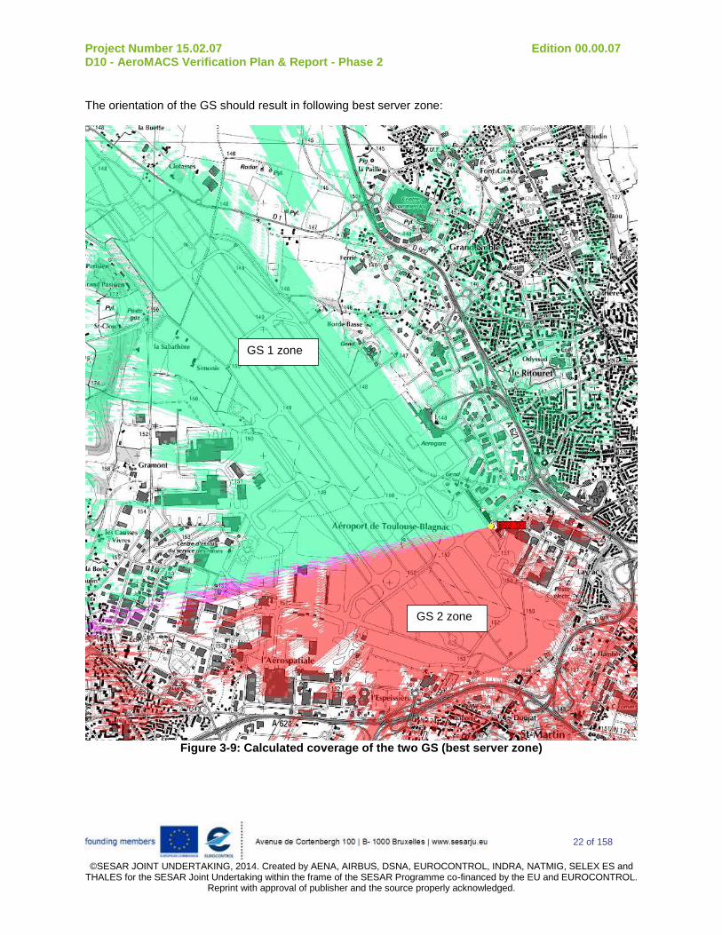
The orientation of the GS should result in following best server zone:
Figure 3-9: Calculated coverage of the two GS (best server zone)
GS 1 zone
GS 2 zone
Project Number 15.02.07 Edition 00.00.07 D10 - AeroMACS Verification Plan & Report - Phase 2
23 of 158
©SESAR JOINT UNDERTAKING, 2014. Created by AENA, AIRBUS, DSNA, EUROCONTROL, INDRA, NATMIG, SELEX ES and
THALES for the SESAR Joint Undertaking within the frame of the SESAR Programme co-financed by the EU and EUROCONTROL. Reprint with approval of publisher and the source properly acknowledged.
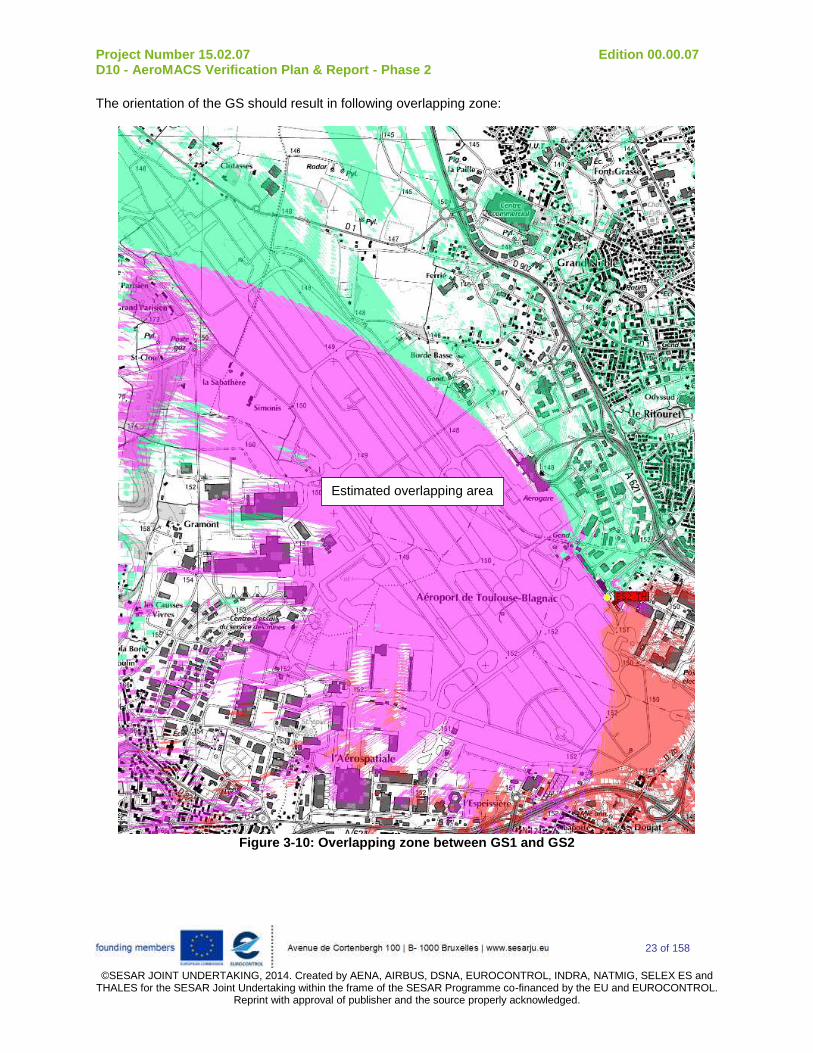
The orientation of the GS should result in following overlapping zone:
Figure 3-10: Overlapping zone between GS1 and GS2
Estimated overlapping area

Project Number 15.02.07 Edition 00.00.07 D10 - AeroMACS Verification Plan & Report - Phase 2
24 of 158
©SESAR JOINT UNDERTAKING, 2014. Created by AENA, AIRBUS, DSNA, EUROCONTROL, INDRA, NATMIG, SELEX ES and
THALES for the SESAR Joint Undertaking within the frame of the SESAR Programme co-financed by the EU and EUROCONTROL. Reprint with approval of publisher and the source properly acknowledged.
3.5.3.3 Fix MS integration
The fixed MS is located on a DSNA building near position PB on above map.
Figure 3-11: fix MS location
The MS and the antenna are setup on the roof and an Ethernet cable is coming down to the working position as depicted in following picture.
Figure 3-12: MS fix location

Project Number 15.02.07 Edition 00.00.07 D10 - AeroMACS Verification Plan & Report - Phase 2
25 of 158
©SESAR JOINT UNDERTAKING, 2014. Created by AENA, AIRBUS, DSNA, EUROCONTROL, INDRA, NATMIG, SELEX ES and
THALES for the SESAR Joint Undertaking within the frame of the SESAR Programme co-financed by the EU and EUROCONTROL. Reprint with approval of publisher and the source properly acknowledged.
Figure 3-13: MS setup
3.5.3.4 Mobile MS integration Two MS will also be installed in DSNA vehicles. In the picture below the setup is represented. The MS antenna is installed on the vehicle roof as well as a GPS antenna to record the vehicle position with the PC.
Figure 3-14: Setup of MS in the vehicles
Figure 3-15: Items integrated in the vehicles
Mechanical
interface
Antenna
50 W load
MS
GPS
Battery
PoE
AC/DC converter
Ethernet
PC
12 V
220 V
220 VEth.+48V
RF
RS232
MS
GPS
Battery
PoE
AC/DC converter
Ethernet
PC
12 V
220 V
220 VEth.+48V
RF
RS232
RF
Alternate case with second antenna (MIMO option)

Project Number 15.02.07 Edition 00.00.07 D10 - AeroMACS Verification Plan & Report - Phase 2
26 of 158
©SESAR JOINT UNDERTAKING, 2014. Created by AENA, AIRBUS, DSNA, EUROCONTROL, INDRA, NATMIG, SELEX ES and
THALES for the SESAR Joint Undertaking within the frame of the SESAR Programme co-financed by the EU and EUROCONTROL. Reprint with approval of publisher and the source properly acknowledged.
3.5.3.5 Scenarios and associated verification activities
The verification objectives (VO) devoted to the Toulouse Airport P15.02.07 test campaign are summarized in following tables. They can be found in D05.2 document [1].
General VO Id Title Purpose
AeroMACS_VO_Interop_02 Link adaptation Assess the different modulation schemes and the throughput hence supported.
AeroMACS_VO_Interop_04 Quality of Service Verify that the MS-BS interface supports nrtPS, rtPS and BE QoS classes.
AeroMACS_VO_Interop_06 MS channel quality report
Verify the Fast Feedback Channel Allocation of the BS in order to get information on the currently SNR the MS has.
AeroMACS_VO_RF_01 Cell Coverage Verify the cell coverage
AeroMACS_VO_RF_04 Channel selectivity Verify the receiver Adjacent and non-adjacent channel selectivity (in max speed)
AeroMACS_VO_RF_08 Transmit power requirements
Verify AeroMACS Transmit power requirements
AeroMACS_VO_RF_09 MS scanning performance
Verify that MS can perform the frequency and channel scanning within the required durations.
AeroMACS_VO_RF_10 MS ranging performance
Verify the successful completion of the ranging process
AeroMACS_VO_RFReal_02 Real deployment Characterize the coverage (signal strength) in real testing environment.
AeroMACS_VO_RFReal_03 Modulations performances
Characterize the performances of the AeroMACS modulations in real environment (uplink and downlink data latency, round-trip time, real throughput available, jitter…).
AeroMACS_VO_RFReal_04 NLOS performances Evaluate the impacts of obstructions (such as buildings…) on the coverage.
AeroMACS_VO_RFReal_07 Multi-channel utilization
Validate the possibility to communicate simultaneously on several channels without interference or impact on performances from one channel to the other (Alternate and adjacent Channel)
AeroMACS_VO_RFReal_08 Mobility performances Evaluate the impact of mobility on the communications.
Table 4: VO summary

Project Number 15.02.07 Edition 00.00.07 D10 - AeroMACS Verification Plan & Report - Phase 2
27 of 158
©SESAR JOINT UNDERTAKING, 2014. Created by AENA, AIRBUS, DSNA, EUROCONTROL, INDRA, NATMIG, SELEX ES and
THALES for the SESAR Joint Undertaking within the frame of the SESAR Programme co-financed by the EU and EUROCONTROL. Reprint with approval of publisher and the source properly acknowledged.
The scenarios are built regarding the different categories of objective:
- Cell coverage / MS channel quality report:
o Objective: verify the maximum distance in the airport where the datalink is synchronized and get information on the SNR of the MS and on the received level with spectrum analyzer.
o Means: one mobile MS and one BS are used at a time, two people from Thales and one from DSNA (qualified driver), one spectrum analyzer in the car
o Method: The vehicle is driven to different points on the Airport where it is stopped to perform the measurements.
The “route de service’ in green in following picture is used in order to cover the whole airport (e.g.: near points T50, P3, P5, ATE, P7, S50, S30, P9) while maintaining LOS conditions
Measured at each point: Vehicle position through GPS, radio statistics (RSSI, CINR, modulation...) through interrogation of the MS and GS, and data transmission performances (max throughput, jitter and delay) via iPerf and Ping.
- Modulation performances / Link adaptation:
o Objective: assess the different modulation schemes and the throughput hence supported, characterize the performances of the modulations in real environment
o Means: one mobile MS and one BS are used at a time, two people from Thales and one from DSNA (qualified driver)
o Method: The vehicle is driven to a point on the Airport where it is stopped to perform the measurement.
The “route de service’ is used, the stop point is selected with a good coverage so as to be able to test all the modulation and coding schemes.
Measured at each point: Vehicle position through GPS, radio statistics (RSSI, CINR, modulation...) through interrogation of the MS and GS, and data transmission performances (max throughput, jitter and delay) via iPerf and Ping.
- Real deployment / NLOS performances
o Objective: Evaluate the impact of buildings, hangars on the strength of the signal
o Means: one mobile MS and one BS are used at a time, two people from Thales and one
from DSNA (qualified driver)
o Method: Method is similar to the one described for cell coverage, but in this case stop
points are spots where communications are established in near-LOS or Non-LOS
conditions. As far as possible (depending on authorization), the different kind of zones of
the Airport are visited: ramp Area, parking Area, Tower Area, Access roads to air
navigation installations for maintenance operations (note: Taxiway used during the
mobility tests).
- Mobility performances / Channel selectivity:
o Objective: Evaluate the impact of mobility on the data communications and channel selectivity.

Project Number 15.02.07 Edition 00.00.07 D10 - AeroMACS Verification Plan & Report - Phase 2
28 of 158
©SESAR JOINT UNDERTAKING, 2014. Created by AENA, AIRBUS, DSNA, EUROCONTROL, INDRA, NATMIG, SELEX ES and
THALES for the SESAR Joint Undertaking within the frame of the SESAR Programme co-financed by the EU and EUROCONTROL. Reprint with approval of publisher and the source properly acknowledged.
o Means: one mobile MS and one BS are used at a time, two people from Thales and one from DSNA (qualified driver). Then one MS and two BS at max speed to check selectivity.
o Method:
0 km/h: first general performance before mobility is recorded.
At 50 km/h: uses of taxiway or runway (depending upon authorization),
parameters are recorded while driving at a constant speed of 50 km/h, MS being
preliminary registered to the servicing BS.
At 90 km/h: use of runway or taxiway (depending upon authorization and vehicle
capacity)
- Multi-channel utilization:
o Objective: Evaluate the impact of two BS with overlapping coverage and using alternate or adjacent channels.
o Means: one to three MS and two BS are used at a time, two to three people from Thales and two from DSNA (qualified drivers)
o Method: The vehicle is driven on different points in the overlapped area (“route of service” is used).
The 2 GS channels are either separated from 5 MHz (adjacent channels) or 10 MHz (alternate channels), MS is registered to the GS offering the best signal strength at the point.
Measured at each point: Vehicle position through GPS, radio statistics (RSSI, CINR, modulation...) through interrogation of the MS and GS, and data transmission performances (max throughput, jitter, delay) via iPerf and Ping
- Quality of service:
o Objective: Verify that the MS-BS interface supports nrtPS, rtPS and BE QoS classes.
o Means: one MS (fix location) and one GS, two people from Thales
o Method: The different SF are programmed on the GS and allocated to the MS. Through iPerf, communications are generated between GS and MS with controlled data rates. Then it is verified that data traffic exceeding the Maximum Sustained Traffic Rate QoS value related to a SF is dropped or delayed.
- Transmit power requirements:
o Objective: Verify AeroMACS Transmit power requirements
o Means: one MS (fix location) and one GS, two people from Thales, one spectrum analyser with additional antenna.
o Method: through iPerf, communications are generated between GS and MS. The mean EIRP is measured during the transmission via the spectrum analyser.
- MS scanning and ranging performance:

Project Number 15.02.07 Edition 00.00.07 D10 - AeroMACS Verification Plan & Report - Phase 2
29 of 158
©SESAR JOINT UNDERTAKING, 2014. Created by AENA, AIRBUS, DSNA, EUROCONTROL, INDRA, NATMIG, SELEX ES and
THALES for the SESAR Joint Undertaking within the frame of the SESAR Programme co-financed by the EU and EUROCONTROL. Reprint with approval of publisher and the source properly acknowledged.
o Objective: Verify that MS can perform the frequency and channel scanning within the required durations and successful completion of the ranging process
o Means: one MS (fix location) and one GS, two people from Thales.
o Method: through iPerf, communications are generated between GS and MS. A list of frequencies is programmed on the MS between 5091 and 5150 MHz and the connection time is measured and connection processed including ranging is observed:
One frequency is programmed 5093,5 MHz
Two frequencies are programmed: 5093,5 MHz & 5103.5 MHz
A scan band with frequency step of 250 kHz: 5093,5 – 5147,5 MHz / step 250 kHz.

Project Number 15.02.07 Edition 00.00.07 D10 - AeroMACS Verification Plan & Report - Phase 2
30 of 158
©SESAR JOINT UNDERTAKING, 2014. Created by AENA, AIRBUS, DSNA, EUROCONTROL, INDRA, NATMIG, SELEX ES and THALES for the SESAR Joint Undertaking within the
frame of the SESAR Programme co-financed by the EU and EUROCONTROL. Reprint with approval of publisher and the source properly acknowledged.
Figure 3-16: Test location in Toulouse Airport
Route de service (P5 is the farthest point), used for cell coverage
Runways (32L – 14R and 32R – 14L), used for mobility at 90 km/h
Whisky Taxiway (W20 – W100), used for mobility up to 50 km/h
Mobile MS on “route de service” Fix MS
Mobile MS on runway
Mobile MS on taxiway
BS 1 + BS2 on former control tower

Project Number 15.02.07 Edition 00.00.07 D10 - AeroMACS Verification Plan & Report - Phase 2
31 of 158
©SESAR JOINT UNDERTAKING, 2014. Created by AENA, AIRBUS, DSNA, EUROCONTROL, INDRA, NATMIG, SELEX ES and THALES
for the SESAR Joint Undertaking within the frame of the SESAR Programme co-financed by the EU and EUROCONTROL. Reprint with approval of publisher and the source properly acknowledged.
3.6 Acceptance criteria
The 15.02.07 project is a technological project where the verification approach consists in assessing and collecting evidences on the performances of the proposed AeroMACS technology against the on-going standardization.
In terms of acceptance, for each test case, a paragraph (cf. § A.x.y.3) called “verification exercise results” analyses if the tests results are in compliance with the AeroMACS standardization (cf. § Ax.y.3.2). Any unexpected behaviour is mentioned and its impact is further assessed (cf. § A.x.y.3.3). Finally, based on the test results, recommendations are drawn (cf. § A.x.y.4).
Chapter 5 summarizes and draws the whole picture about the tests results (whether each Verification test achieves the corresponding verification objective expectations or not) while chapter 6 summarizes the recommendations.
Based on these test results, an availability note will be issued by each vendor to state if tested devices are ready for system/platform integration.

Project Number 15.02.07 Edition 00.00.07 D10 - AeroMACS Verification Plan & Report - Phase 2
32 of 158
©SESAR JOINT UNDERTAKING, 2014. Created by AENA, AIRBUS, DSNA, EUROCONTROL, INDRA, NATMIG, SELEX ES and THALES
for the SESAR Joint Undertaking within the frame of the SESAR Programme co-financed by the EU and EUROCONTROL. Reprint with approval of publisher and the source properly acknowledged.
4 Verification Activities
4.1 Verification Exercises List
The phase 2 verification exercises (test cases) are derived in Appendix A from the Verification Objectives’ list defined in D05.2 [1].
Each company (SELEX or THALES) describes the test cases related to the verification objectives it owns. Tests cases are described depending on the tests means involved and can covers several verification objectives. They describe into details the various tests to be executed in each company test environments. Each test case will contain one test objective, a brief description, a reference to the test bench used (as identified in 3.5.2 for lab tests and in 3.5.3 for Airport tests), and the detailed test procedure.
4.1.1 Thales lab and airport test cases identification
This Chapter contains the summary of laboratory test cases to be done by THALES in phase 1. All defined lab test cases have been reported in the following table and are detailed in the appendix. For each test case all the VO’s addressed by that particular test are shown in the table. The complete list of VOs is reported in D05.2 document (ref. [1]).
The test case number is identified TLAB2_XXX or TAIR_XXX, where:
TLAB2: means Thales LABoratory test – phase 2
TAIR: means Thales AIRport test
XXX: is the test identification number
Test Case nr.
Test Case Name Lab. Environment
VO’s addressed
TLAB2_010 Service flows control
Lab_test_bed_01 AeroMACS_VO_Interop_05 B/C
TLAB2_020 channel selectivity and transmit power measurements
Lab_test_bed_01 AeroMACS_VO_RF_04 B/C AeroMACS_VO_RF_05 A/B AeroMACS_VO_RF_08 E
TLAB2_030 MS channel quality report and MS transmit synchronisation
Lab_test_bed_01 AeroMACS_VO_Interop_06 A/B AeroMACS_VO_RF_11 A
TLAB2_040 IOT test between Thales GS and Selex MS
Lab_test_bed_01 with Selex MS
AeroMACS_VO_Limited Interop A/B/C/D/E
Table 5: identification of Phase 2 Thales lab test cases
Project Number 15.02.07 Edition 00.00.07 D10 - AeroMACS Verification Plan & Report - Phase 2
33 of 158
©SESAR JOINT UNDERTAKING, 2014. Created by AENA, AIRBUS, DSNA, EUROCONTROL, INDRA, NATMIG, SELEX ES and THALES
for the SESAR Joint Undertaking within the frame of the SESAR Programme co-financed by the EU and EUROCONTROL. Reprint with approval of publisher and the source properly acknowledged.
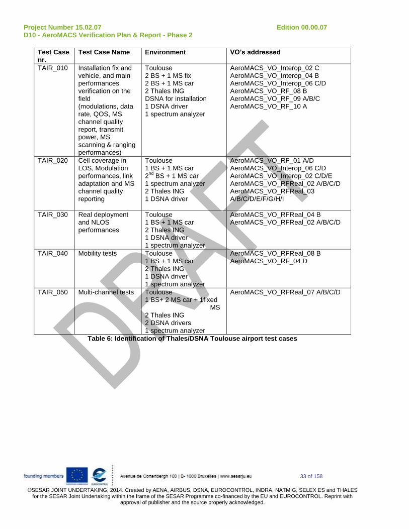
Test Case nr.
Test Case Name Environment VO’s addressed
TAIR_010 Installation fix and vehicle, and main performances verification on the field (modulations, data rate, QOS, MS channel quality report, transmit power, MS scanning & ranging performances)
Toulouse 2 BS + 1 MS fix 2 BS + 1 MS car 2 Thales ING DSNA for installation 1 DSNA driver 1 spectrum analyzer
AeroMACS_VO_Interop_02 C AeroMACS_VO_Interop_04 B AeroMACS_VO_Interop_06 C/D AeroMACS_VO_RF_08 B AeroMACS_VO_RF_09 A/B/C AeroMACS_VO_RF_10 A
TAIR_020 Cell coverage in LOS, Modulation performances, link adaptation and MS channel quality reporting
Toulouse 1 BS + 1 MS car 2
nd BS + 1 MS car
1 spectrum analyzer 2 Thales ING 1 DSNA driver
AeroMACS_VO_RF_01 A/D AeroMACS_VO_Interop_06 C/D AeroMACS_VO_Interop_02 C/D/E AeroMACS_VO_RFReal_02 A/B/C/D AeroMACS_VO_RFReal_03 A/B/C/D/E/F/G/H/I
TAIR_030 Real deployment and NLOS performances
Toulouse 1 BS + 1 MS car 2 Thales ING 1 DSNA driver 1 spectrum analyzer
AeroMACS_VO_RFReal_04 B AeroMACS_VO_RFReal_02 A/B/C/D
TAIR_040 Mobility tests
Toulouse 1 BS + 1 MS car 2 Thales ING 1 DSNA driver 1 spectrum analyzer
AeroMACS_VO_RFReal_08 B AeroMACS_VO_RF_04 D
TAIR_050
Multi-channel tests Toulouse 1 BS+ 2 MS car + 1fixed MS 2 Thales ING 2 DSNA drivers 1 spectrum analyzer
AeroMACS_VO_RFReal_07 A/B/C/D
Table 6: Identification of Thales/DSNA Toulouse airport test cases

Project Number 15.02.07 Edition 00.00.07 D10 - AeroMACS Verification Plan & Report - Phase 2
34 of 158
©SESAR JOINT UNDERTAKING, 2014. Created by AENA, AIRBUS, DSNA, EUROCONTROL, INDRA, NATMIG, SELEX ES and THALES
for the SESAR Joint Undertaking within the frame of the SESAR Programme co-financed by the EU and EUROCONTROL. Reprint with approval of publisher and the source properly acknowledged.
4.1.2 Selex lab test cases identification This Chapter contains the summary of laboratory test cases to be done by SELEX in phase 2. All defined lab test cases have been reported in the following table and are detailed in the appendix. For each Test Case all the VO’s addressed by that particular test are shown in the table. The complete list of VOs is reported in D05.2 document (ref. [1]).
Lab Test
Case nr.
Test Case Name Lab.
Environment
VO’s addressed
P2_LAB1_1 Connection Re-establishment Lab_test_bed_02 AeroMACS_VO_Interop_03_B
P2_LAB1_2 Power Control Lab_test_bed_02 AeroMACS_VO_Interop_06_A/B AeroMACS_VO_Interop_10_C/D
P2_LAB1_3 Quality of Service Lab_test_bed_02 AeroMACS_VO_Interop_07_B/C
P2_LAB1_4 Security Lab_test_bed_02 AeroMACS_VO_Interop_11_C/D/F
P2_LAB1_5 Radio Performance Lab_test_bed_02 AeroMACS_VO_RF_04_A AeroMACS_VO_RFReal_01_B
P2_LAB_6 IOT between Selex Ground System and Thales MS
Lab_test_bed_02 AeroMACS_VO_Limited Interop A/B/C/D/E
Table 7: identification of Phase 2 Selex lab test cases

Project Number 15.02.07 Edition 00.00.07 D10 - AeroMACS Verification Plan & Report - Phase 2
35 of 158
©SESAR JOINT UNDERTAKING, 2014. Created by AENA, AIRBUS, DSNA, EUROCONTROL, INDRA, NATMIG, SELEX ES and THALES
for the SESAR Joint Undertaking within the frame of the SESAR Programme co-financed by the EU and EUROCONTROL. Reprint with approval of publisher and the source properly acknowledged.
4.2 Verification activities master schedule
The steps of the verification plan are summarized on the diagram below.
Figure 4-1 : 15.02.07 Verification Activities
The latest Integration and Testing phase 2 schedule is given in following picture:
Figure 4-2 : Integration and Testing Phase 2 schedule

Project Number 15.02.07 Edition 00.00.07 D10 - AeroMACS Verification Plan & Report - Phase 2
36 of 158
©SESAR JOINT UNDERTAKING, 2014. Created by AENA, AIRBUS, DSNA, EUROCONTROL, INDRA, NATMIG, SELEX ES and THALES
for the SESAR Joint Undertaking within the frame of the SESAR Programme co-financed by the EU and EUROCONTROL. Reprint with approval of publisher and the source properly acknowledged.
5 Verification exercises Results
5.1 Summary of Verification Exercises Results The results of the different Verification test cases analysed in appendix A are summarized in following tables:
OK: Verification test achieves the verification objective expectations
NOK (Non OK): Verification test does not achieve the verification objective expectations
POK (Partially OK): Verification test achieves partially the verification objective expectations
NT (Not Tested): Verification test not performed.
Test Case nr.
Test Case Name VO’s addressed Result
TLAB2_010 Service flows control AeroMACS_VO_Interop_05 B/C
OK
TLAB2_020 channel selectivity and transmit power measurements
AeroMACS_VO_RF_04 B/C AeroMACS_VO_RF_05 A/B AeroMACS_VO_RF_08 E
OK
TLAB2_030 MS channel quality report and MS transmit synchronisation
AeroMACS_VO_Interop_06 A/B AeroMACS_VO_RF_11 A
OK
TLAB2_040 IOT between Thales GS and Selex MS AeroMACS_VO_Limited_ Interop A/B/C/D/E
pOK
Table 8: Summary of Thales lab tests results for phase 2
Lab Test
Case nr.
Test Case Name VO’s addressed Result
P2_LAB1_1 Connection Re-establishment AeroMACS_VO_Interop_03_ B OK
P2_LAB1_2 Power Control AeroMACS_VO_Interop_06_A/B AeroMACS_VO_Interop_10_ C/D
OK
P2_LAB1_3 Quality of Service AeroMACS_VO_Interop_07_ B/C OK
P2_LAB1_4 Security AeroMACS_VO_Interop_11_C/D/F OK
P2_LAB1_5 Radio Performance AeroMACS_VO_RF_04_A
AeroMACS_VO_RFReal_01_B
OK
P2_LAB_6 IOT between Selex Ground System and Thales MS
AeroMACS_VO_Limited Interop A/B/C/D/E
pOK
Table 9: Summary of Selex Lab. tests results for phase 2

Project Number 15.02.07 Edition 00.00.07 D10 - AeroMACS Verification Plan & Report - Phase 2
37 of 158
©SESAR JOINT UNDERTAKING, 2014. Created by AENA, AIRBUS, DSNA, EUROCONTROL, INDRA, NATMIG, SELEX ES and THALES
for the SESAR Joint Undertaking within the frame of the SESAR Programme co-financed by the EU and EUROCONTROL. Reprint with approval of publisher and the source properly acknowledged.
Test Case nr.
Test Case Name VO’s addressed Result
TAIR_010 Installation and main performances verification (modulations, data rate, QOS, MS channel quality report, transmit power, MS scanning & ranging performances)
AeroMACS_VO_Interop_02 C AeroMACS_VO_Interop_04 B AeroMACS_VO_Interop_06 C/D AeroMACS_VO_RF_08 B AeroMACS_VO_RF_09 A/B/C AeroMACS_VO_RF_10 A
OK
TAIR_020 Cell coverage in LOS, Modulation performances, link adaptation, and MS channel quality reporting
AeroMACS_VO_RF_01 A/D AeroMACS_VO_Interop_06 C/D AeroMACS_VO_Interop_02 C/D/E AeroMACS_VO_RFReal_03 A/B/C/D/E/F/G/H/I AeroMACS_VO_RFReal_02 A/B/C/D
OK
TAIR_030 Real deployment and NLOS performances
AeroMACS_VO_RFReal_04 B AeroMACS_VO_RFReal_02 A/B/C/D
OK
TAIR_050 Mobility tests
AeroMACS_VO_RFReal_08 B AeroMACS_VO_RF_04 D
OK
TAIR_060
Multi-channel tests AeroMACS_VO_RFReal_07 A/B/C/D OK
Table 10: Summary of Thales/DSNA Airport tests results
5.2 Analysis of Verification Exercises Results
The detailed analysis of the verification Exercises can be found in each verification exercise report in Appendix A.
Indeed, each verification exercise has a dedicated paragraph: “Ax.y.3.2 Analysis of Verification Exercise Results”.
Each test case was performed successfully regarding the related verification objectives except IOT between vendors’ devices:
TLAB2_040: IOT between Thales BS and Selex MS performed on THALES Lab_test_bed_01 was only partially successful. Only Scanning was completed successfully, with proper identification of the BS Preamble by MS side. Synchronization was not successfully completed, as the Selex MS indicated a FCH decoding failed. The reasons of this interoperability issue should be investigated in a further IOT activity beyond P15.02.07.
P2_LAB_6: IOT between Selex BS and Thales MS performed on SELEX ES Lab_test_bed_02 was partially successful: authentication was not successful finalizing with an Authentication Failure. Further investigation beyond P15.02.07 is recommended in the security field.

Project Number 15.02.07 Edition 00.00.07 D10 - AeroMACS Verification Plan & Report - Phase 2
38 of 158
©SESAR JOINT UNDERTAKING, 2014. Created by AENA, AIRBUS, DSNA, EUROCONTROL, INDRA, NATMIG, SELEX ES and THALES
for the SESAR Joint Undertaking within the frame of the SESAR Programme co-financed by the EU and EUROCONTROL. Reprint with approval of publisher and the source properly acknowledged.
6 Conclusions and recommendations
The main objective of the integration & testing work area of P15.02.07 is to assess the performances of AeroMACS prototypes.
The phase 1 lab measurements (see ref. [3]) gave a good characterization of the prototypes with positive test results. This gave a good confidence before the field testing.
The phase 2 testing, the results of which are reported in the present document, allowed gathering additional measurements in lab and real environment of the Airport surface datalink and thus complement significantly the assessment of the AeroMACS technology in ground segment context with some important information as cell coverage, LOS / nLOS / NLOS propagation behaviour, mobility effect....
Interoperability between Thales and Selex ES prototypes was tested in both senses (Selex Mobile Station versus Thales Ground System and vice versa), but, despite numerous efforts from P15.02.07 teams, it has not been completely achieved. The details of the Interoperability tests performed are provided in A.1.6 and A.2.4. The test campaigns executed suggest further investigations being required in the field of Interoperability, and also confirm the need to identify unambiguously the WiMAX network protocols and messages formatting involved in the Authentication/Encryption process.
Planning ad-hoc activities with the purpose to complete IOT and to cover the network and security (e.g certificates) layers in the near future (SESAR2020/VLD could be suitable opportunities) in coordination with the relevant standardization authorities is thus recommended.
As a conclusion, both lab and Airport testing allowed collecting positive evidences on the suitability of the prototypes to assess the AeroMACS technology regarding the on-going standardization, to prefigure future realizations, and representative airport deployments, which are highly recommended to complete P15.2.7 achievements at the upper layer, namely network layer.

Project Number 15.02.07 Edition 00.00.07 D10 - AeroMACS Verification Plan & Report - Phase 2
39 of 158
©SESAR JOINT UNDERTAKING, 2014. Created by AENA, AIRBUS, DSNA, EUROCONTROL, INDRA, NATMIG, SELEX ES and THALES
for the SESAR Joint Undertaking within the frame of the SESAR Programme co-financed by the EU and EUROCONTROL. Reprint with approval of publisher and the source properly acknowledged.
7 References
7.1 Reference Documents
The following documents were used to provide input:
[1] P 15.02.07 D05.2 - AeroMACS Verification Strategy
[2] P 15.02.07 D05.1 - AeroMACS prototypes description
[3] P 15.02.07 D06 - AeroMACS integration & testing – phase 1
[4] http://freeradius.org/
[5] P15.02.07 D04- AeroMACS Deployment & Integration Analysis

Project Number 15.02.07 Edition 00.00.07 D10 - AeroMACS Verification Plan & Report - Phase 2
40 of 158
©SESAR JOINT UNDERTAKING, 2014. Created by AENA, AIRBUS, DSNA, EUROCONTROL, INDRA, NATMIG, SELEX ES and THALES
for the SESAR Joint Undertaking within the frame of the SESAR Programme co-financed by the EU and EUROCONTROL. Reprint with approval of publisher and the source properly acknowledged.
Appendix A Phase 2 verification exercises and results

Project Number 15.02.07 Edition 00.00.07 D10 - AeroMACS Verification Plan & Report - Phase 2
41 of 158
©SESAR JOINT UNDERTAKING, 2014. Created by AENA, AIRBUS, DSNA, EUROCONTROL, INDRA, NATMIG, SELEX ES and THALES
for the SESAR Joint Undertaking within the frame of the SESAR Programme co-financed by the EU and EUROCONTROL. Reprint with approval of publisher and the source properly acknowledged.
A.1 Selex lab verification exercises
A.1.1 Verification Exercise # P2_LAB1_1 Connection Re-Establishment
A.1.1.1 Verification Exercise Scope
The purpose of this Test Case is verifying that the MS after a signal loss (in Network Re-entry) is able to re-establish the DL Synchronization.
A.1.1.2 Conduct of Verification Exercise
A.1.1.2.1 Verification Exercise Preparation
The test bed described in Figure 3-2 was arranged.
Equipment:
ASN-GW is an Aricent Wing ASN-GW.
MS, BS and ASN-GW were linked together according to test bed configuration with proper attenuation and switched on.
Fading Simulator and Data Traffic Generators shown in Figure 3-2 were not used in this test.
A.1.1.2.2 Verification Exercise execution
Step nr. Action Action description
(if needed)
PCO (Point of Control
and Observation)
Result
1. Switch on MS OK
2. Verify that MS begins
scanning for BS
Mngt PC
connected to MS
OK
3. Switch on BS OK
4. Configure BS to one
channel (e.g. 5091 MHz)
OK
5 Reboot BS OK
6. Verify that MS connects
successfully
Mngt PCs
connected to MS
and BS
OK
7. Increase attenuation until
the MS loses the
Variable attenuator
and Mngt PCs
connected to MS
OK

Project Number 15.02.07 Edition 00.00.07 D10 - AeroMACS Verification Plan & Report - Phase 2
42 of 158
©SESAR JOINT UNDERTAKING, 2014. Created by AENA, AIRBUS, DSNA, EUROCONTROL, INDRA, NATMIG, SELEX ES and THALES
for the SESAR Joint Undertaking within the frame of the SESAR Programme co-financed by the EU and EUROCONTROL. Reprint with approval of publisher and the source properly acknowledged.
connection with BS and BS
8. Verify that the MS is able
to re-establish the DL
Synchronization.
Mngt PCs
connected to MS
and BS
OK

Project Number 15.02.07 Edition 00.00.07 D10 - AeroMACS Verification Plan & Report - Phase 2
43 of 158
©SESAR JOINT UNDERTAKING, 2014. Created by AENA, AIRBUS, DSNA, EUROCONTROL, INDRA, NATMIG, SELEX ES and THALES for the SESAR Joint Undertaking within the
frame of the SESAR Programme co-financed by the EU and EUROCONTROL. Reprint with approval of publisher and the source properly acknowledged.
A.1.1.2.3 Deviation from the planned activities
None.
A.1.1.3 Verification exercise Results
A.1.1.3.1 Summary of Verification exercise Results
ID Result Description When
observed?
Expected result Obtained result VO
1 Resynchronization Verify that the
MS after a
signal loss (in
Network Re-
entry) is able to
re-establish the
DL
Synchronization
.
Step 8 Resynchronization OK AeroMACS_VO_Interop_03_B

Project Number 15.02.07 Edition 00.00.07 D10 - AeroMACS Verification Plan & Report - Phase 2
44 of 158
©SESAR JOINT UNDERTAKING, 2014. Created by AENA, AIRBUS, DSNA, EUROCONTROL, INDRA, NATMIG, SELEX ES and THALES
for the SESAR Joint Undertaking within the frame of the SESAR Programme co-financed by the EU and EUROCONTROL. Reprint with approval of publisher and the source properly acknowledged.
A.1.1.3.2 Analysis of Verification Exercise Results
As a test preamble, the various phases of the normal Initial Network Entry was executed by BS and MS (test step no. 6). Figure 7-1 shows the last step (MS DHCP Registration),
Figure 7-1: MS Log - Initial Net Entry: MS Registration
After the address assignment to the MS, the attenuation between MS and BS was gradually increased; this caused a Link Loss, with a subsequent Network Exit by the MS side (see Figure 7-2).

Project Number 15.02.07 Edition 00.00.07 D10 - AeroMACS Verification Plan & Report - Phase 2
45 of 158
©SESAR JOINT UNDERTAKING, 2014. Created by AENA, AIRBUS, DSNA, EUROCONTROL, INDRA, NATMIG, SELEX ES and THALES
for the SESAR Joint Undertaking within the frame of the SESAR Programme co-financed by the EU and EUROCONTROL. Reprint with approval of publisher and the source properly acknowledged.
Figure 7-2: Forced Link Loss and Network Exit
Subsequently, the attenuation between MS and BS was gradually decreased, until the MS correctly repeated the Network Entry (Figure 7-3).

Project Number 15.02.07 Edition 00.00.07 D10 - AeroMACS Verification Plan & Report - Phase 2
46 of 158
©SESAR JOINT UNDERTAKING, 2014. Created by AENA, AIRBUS, DSNA, EUROCONTROL, INDRA, NATMIG, SELEX ES and THALES
for the SESAR Joint Undertaking within the frame of the SESAR Programme co-financed by the EU and EUROCONTROL. Reprint with approval of publisher and the source properly acknowledged.
Figure 7-3: Network Re-entry
A.1.1.3.3 Unexpected behaviors/results
None.
A.1.1.4 Conclusions and recommendations The testing allowed checking successfully the correct Network Re-entry of the MS after a signal loss.
TX
192.168.0.67
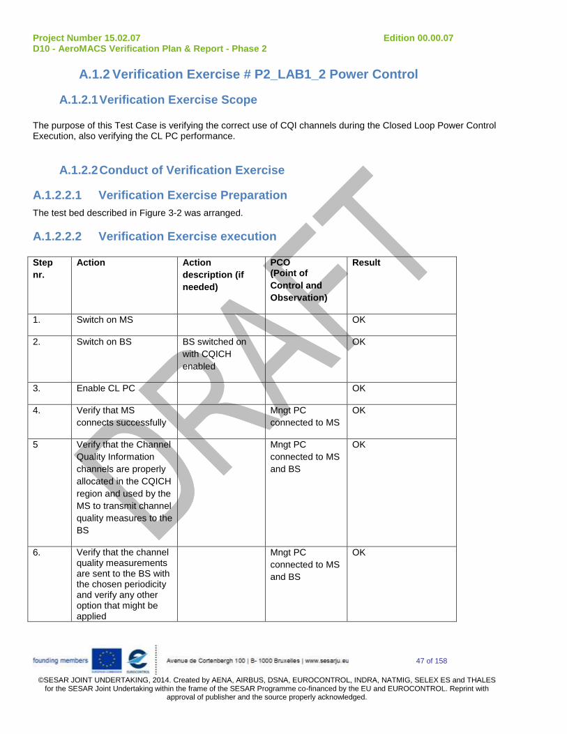
Project Number 15.02.07 Edition 00.00.07 D10 - AeroMACS Verification Plan & Report - Phase 2
47 of 158
©SESAR JOINT UNDERTAKING, 2014. Created by AENA, AIRBUS, DSNA, EUROCONTROL, INDRA, NATMIG, SELEX ES and THALES
for the SESAR Joint Undertaking within the frame of the SESAR Programme co-financed by the EU and EUROCONTROL. Reprint with approval of publisher and the source properly acknowledged.
A.1.2 Verification Exercise # P2_LAB1_2 Power Control
A.1.2.1 Verification Exercise Scope
The purpose of this Test Case is verifying the correct use of CQI channels during the Closed Loop Power Control Execution, also verifying the CL PC performance.
A.1.2.2 Conduct of Verification Exercise
A.1.2.2.1 Verification Exercise Preparation
The test bed described in Figure 3-2 was arranged.
A.1.2.2.2 Verification Exercise execution
Step
nr.
Action Action
description (if
needed)
PCO (Point of
Control and
Observation)
Result
1. Switch on MS OK
2. Switch on BS BS switched on
with CQICH
enabled
OK
3. Enable CL PC OK
4. Verify that MS
connects successfully
Mngt PC
connected to MS
OK
5 Verify that the Channel
Quality Information
channels are properly
allocated in the CQICH
region and used by the
MS to transmit channel
quality measures to the
BS
Mngt PC
connected to MS
and BS
OK
6. Verify that the channel quality measurements are sent to the BS with the chosen periodicity and verify any other option that might be applied
Mngt PC
connected to MS
and BS
OK

Project Number 15.02.07 Edition 00.00.07 D10 - AeroMACS Verification Plan & Report - Phase 2
48 of 158
©SESAR JOINT UNDERTAKING, 2014. Created by AENA, AIRBUS, DSNA, EUROCONTROL, INDRA, NATMIG, SELEX ES and THALES
for the SESAR Joint Undertaking within the frame of the SESAR Programme co-financed by the EU and EUROCONTROL. Reprint with approval of publisher and the source properly acknowledged.
7. Verify that closed loop parameters remain within specified tolerances
Mngt PC
connected to MS
and BS
OK
8. Verify that closed loop
PC satisfactorily
counteracts channel
gain variations up to
30 dB/s
Mngt PC
connected to MS
and BS
OK

Project Number 15.02.07 Edition 00.00.07 D10 - AeroMACS Verification Plan & Report - Phase 2
49 of 158
©SESAR JOINT UNDERTAKING, 2014. Created by AENA, AIRBUS, DSNA, EUROCONTROL, INDRA, NATMIG, SELEX ES and THALES for the SESAR Joint Undertaking within the
frame of the SESAR Programme co-financed by the EU and EUROCONTROL. Reprint with approval of publisher and the source properly acknowledged.
A.1.2.2.3 Deviation from the planned activities
None.
A.1.2.3 Verification exercise Results
A.1.2.3.1 Summary of Verification exercise Results
ID Result Description When
observed?
Expected result Obtained
result
VO
1 CQI channels
allocation &
application
Verify that the Channel
Quality Information
channels are properly
allocated in the CQICH
region and used by the
MS to transmit channel
quality measures to the
BS
Step 5 CQI
channels
allocation &
application
OK AeroMACS_VO_Interop_06_A
2. CQI periodicity Verify that the channel
quality measurements
are sent to the BS with
the chosen periodicity
and verify any other
option that might be
applied
Step 6 CQI
periodicity OK AeroMACS_VO_Interop_06_B
3. CL power
control
parameters
Verify that all closed
loop parameters (power
levels, power steps,
power range ...) are all
applied within the
Step 7 CL power
control
parameters
OK AeroMACS_VO_Interop_10_C

Project Number 15.02.07 Edition 00.00.07 D10 - AeroMACS Verification Plan & Report - Phase 2
50 of 158
©SESAR JOINT UNDERTAKING, 2014. Created by AENA, AIRBUS, DSNA, EUROCONTROL, INDRA, NATMIG, SELEX ES and THALES for the SESAR Joint Undertaking within the
frame of the SESAR Programme co-financed by the EU and EUROCONTROL. Reprint with approval of publisher and the source properly acknowledged.
specified tolerances
4. CL power
control
performance
Verify that the closed
loop power control
satisfactorily sustains a
data transfer without
causing any oscillation
or instability in the
system, facing channel
gain variations of up to
30 dB/s
Step 8 CL power
control
performance
OK AeroMACS_VO_Interop_10_D

Project Number 15.02.07 Edition 00.00.07 D10 - AeroMACS Verification Plan & Report - Phase 2
51 of 158
©SESAR JOINT UNDERTAKING, 2014. Created by AENA, AIRBUS, DSNA, EUROCONTROL, INDRA, NATMIG, SELEX ES and THALES
for the SESAR Joint Undertaking within the frame of the SESAR Programme co-financed by the EU and EUROCONTROL. Reprint with approval of publisher and the source properly acknowledged.
A.1.2.3.2 Analysis of Verification Exercise Results MS and BS were switched on, and the Network Entry was completed. The CQICH procedure and Closed Loop Power Control had been previously enabled on the BS, which allocated a CQICH sub-channel to the MS using a CQICH IE (CQICH Allocation IE), in order to allow the MS to send periodic CINR reports. The CQICH Allocation, together with the periodicity expressed in frames (8 in this case) is evidenced in the BS Log file shown in Figure 7-4.
Figure 7-4: BS Log - CQICH Allocation After that, it was observed that the MS started to send periodically its measurements in the allocated CQICH channels. In Figure 7-5 it is possible to appreciate that the measurements periodicity is 8 frames as expected.

Project Number 15.02.07 Edition 00.00.07 D10 - AeroMACS Verification Plan & Report - Phase 2
52 of 158
©SESAR JOINT UNDERTAKING, 2014. Created by AENA, AIRBUS, DSNA, EUROCONTROL, INDRA, NATMIG, SELEX ES and THALES
for the SESAR Joint Undertaking within the frame of the SESAR Programme co-financed by the EU and EUROCONTROL. Reprint with approval of publisher and the source properly acknowledged.
Figure 7-5: CQICH measurements
Finally the Closed Loop Power Control was also successfully verified. In particular, it was verified that the Algorithm was able to face a sudden attenuation of 30 dB/s during a data transfer, without any connection loss. The variable attenuation was manually increased by 30 dBs in about 1 second, and it was verified that the MS did not lose the connection with MS. From the MS log in Figure 7-6 it is possible to appreciate the initial situation, in which RSSI= -43 dBm, and as a consequence the MS is applying a certain TX power offset, evidenced in the picture. After the sudden attenuation by 30 dBs, the BS started commanding power adjustments to the MS, until the TX power offset became 32 dBs higher than the initial one (see “PHY PowOff” in Figure 7-7). Subsequently, the initial attenuation was restored, and the proper working of the MS-BS connection was observed.

Project Number 15.02.07 Edition 00.00.07 D10 - AeroMACS Verification Plan & Report - Phase 2
53 of 158
©SESAR JOINT UNDERTAKING, 2014. Created by AENA, AIRBUS, DSNA, EUROCONTROL, INDRA, NATMIG, SELEX ES and THALES
for the SESAR Joint Undertaking within the frame of the SESAR Programme co-financed by the EU and EUROCONTROL. Reprint with approval of publisher and the source properly acknowledged.
Figure 7-6: CL PC - initial situation

Project Number 15.02.07 Edition 00.00.07 D10 - AeroMACS Verification Plan & Report - Phase 2
54 of 158
©SESAR JOINT UNDERTAKING, 2014. Created by AENA, AIRBUS, DSNA, EUROCONTROL, INDRA, NATMIG, SELEX ES and THALES
for the SESAR Joint Undertaking within the frame of the SESAR Programme co-financed by the EU and EUROCONTROL. Reprint with approval of publisher and the source properly acknowledged.
Figure 7-7: CL PC - Final situation
A.1.2.3.3 Unexpected behaviors/results
None.
A.1.2.4 Conclusions and recommendations
The testing allowed checking successfully the correct use of CQI channels during the Closed Loop Power Control Execution.
A.1.3 Verification Exercise # P2_LAB1_3 Quality of Service
A.1.3.1 Verification Exercise Scope
The purpose of this Test Case is to verify that all QoS related requirements are satisfied (SF creation and deletion, traffic parameters, bandwidth management) for different Scheduling Types and for different traffic priorities, in both directions.
A.1.3.2 Conduct of Verification Exercise
A.1.3.2.1 Verification Exercise Preparation
The test bed described in Figure 3-2 was arranged, except the Spectrum Analyser/Signal Generator and Fading Simulator, which were not needed in this test.

Project Number 15.02.07 Edition 00.00.07 D10 - AeroMACS Verification Plan & Report - Phase 2
55 of 158
©SESAR JOINT UNDERTAKING, 2014. Created by AENA, AIRBUS, DSNA, EUROCONTROL, INDRA, NATMIG, SELEX ES and THALES
for the SESAR Joint Undertaking within the frame of the SESAR Programme co-financed by the EU and EUROCONTROL. Reprint with approval of publisher and the source properly acknowledged.
A.1.3.2.2 Verification Exercise execution
Step nr. Action Action description
(if needed)
PCO (Point of Control
and Observation)
Result
1. Switch on BS OK
2. Set 1 SF (SF1) with the
scheduling type (QoS
class) to be used as 1
among BE/nrtPS/rtPS
Mngt PC
connected to ASN-
GW/AAA
OK
3. Switch on MS OK
4. Start an IP Flow with a
configuration compatible
with the SF Classification
for DL (then for UL) traffic
Using IPERF IPERF @ PC
connected to ASN-
GW x DL (MS x
UL)
OK
5. Verify that the IP packets
are transferred on the air
interface
Using IPERF IPERF @ PC
connected to MS x
DL (ASN-GW x UL)
OK
6. Verify that data exceeding
the MSTR is dropped or
delayed
Using IPERF IPERF @ PC
connected to MS x
DL (ASN-GW x UL)
OK
7. Set 1 additional SF (SF2)
with the same
configuration of the SF of
step 3 except for MSTR
Mngt PC
connected to ASN-
GW/AAA
OK
8. Restart MS OK
9. Start two IP Flow one compatible with SF1 configuration and the other with SF2. SF1 throughput < SF2 throughput SF1 throughput + SF2
throughput > Channel
capacity
Using IPERF IPERF @ PC
connected to ASN-
GW x DL (MS x
UL)
OK
10. Check fairness between
flows
Using IPERF IPERF @ PC
connected to MS x
DL (ASN-GW x UL)
OK

Project Number 15.02.07 Edition 00.00.07 D10 - AeroMACS Verification Plan & Report - Phase 2
56 of 158
©SESAR JOINT UNDERTAKING, 2014. Created by AENA, AIRBUS, DSNA, EUROCONTROL, INDRA, NATMIG, SELEX ES and THALES
for the SESAR Joint Undertaking within the frame of the SESAR Programme co-financed by the EU and EUROCONTROL. Reprint with approval of publisher and the source properly acknowledged.
11. Increase the Traffic
Priority of SF2 (SF2
higher priority than SF1)
Mngt PC
connected to ASN-
GW/AAA
OK
12. Restart MS OK
13. Start two IP Flow one compatible with SF1 configuration and the other with SF2. SF1 throughput > SF2 throughput SF1 throughput + SF2
throughput > Channel
capacity
Using IPERF IPERF @ PC
connected to ASN-
GW x DL (MS x
UL)
OK
14. Check unfairness
between flows (SF1
throughput > SF2
throughput)
Using IPERF IPERF @ PC
connected to MS x
DL (ASN-GW x UL)
OK
15. Switch off MS OK
16. Pass to another
scheduling type (QoS
class) and repeat steps
from 2 to 18 until all types
have been tested
OK

Project Number 15.02.07 Edition 00.00.07 D10 - AeroMACS Verification Plan & Report - Phase 2
57 of 158
©SESAR JOINT UNDERTAKING, 2014. Created by AENA, AIRBUS, DSNA, EUROCONTROL, INDRA, NATMIG, SELEX ES and THALES for the SESAR Joint Undertaking within the
frame of the SESAR Programme co-financed by the EU and EUROCONTROL. Reprint with approval of publisher and the source properly acknowledged.
A.1.3.2.3 Deviation from the planned activities
None.
A.1.3.3 Verification exercise Results
A.1.3.3.1 Summary of Verification exercise Results
ID Result Description When
observed?
Expected result Obtained result VO
1. Priority Verify the behaviour
of two SFs with the
same configuration
except traffic
priorities
Step 14 Step 16
Behaviour of two
SFs with the same
configuration
except traffic
priorities
OK AeroMACS_VO_Interop_04_A
2. MSTR Verify that the
Maximum
Sustained Traffic
Rate value for a SF
is respected
Step 6 Maximum
Sustained Traffic
Rate value for a SF
is respected
OK AeroMACS_VO_Interop_04_B
3. DSA Verify that the
correct DSA
procedure is
implemented
Step 5 Step 6
The correct DSA
procedure is
implemented
OK AeroMACS_VO_Interop_05_A
4. BW allocation Verification of
correct allocation of
the MAC resources
Step 5 Step 6 Step 10
Correct allocation
of the MAC
resources
OK AeroMACS_VO_Interop_07_A AeroMACS_VO_Interop_07_B AeroMACS_VO_Interop_07_C AeroMACS_VO_Interop_07_D

Project Number 15.02.07 Edition 00.00.07 D10 - AeroMACS Verification Plan & Report - Phase 2
58 of 158
©SESAR JOINT UNDERTAKING, 2014. Created by AENA, AIRBUS, DSNA, EUROCONTROL, INDRA, NATMIG, SELEX ES and THALES for the SESAR Joint Undertaking within the
frame of the SESAR Programme co-financed by the EU and EUROCONTROL. Reprint with approval of publisher and the source properly acknowledged.
Step 14 Step 16

Project Number 15.02.07 Edition 00.00.07 D10 - AeroMACS Verification Plan & Report - Phase 2
59 of 158
©SESAR JOINT UNDERTAKING, 2014. Created by AENA, AIRBUS, DSNA, EUROCONTROL, INDRA, NATMIG, SELEX ES and THALES
for the SESAR Joint Undertaking within the frame of the SESAR Programme co-financed by the EU and EUROCONTROL. Reprint with approval of publisher and the source properly acknowledged.
A.1.3.3.2 Analysis of Verification Exercise Results As usual, MS and BS were switched on, and the Network Entry was completed. The attenuation was set at a value such to allow BS and MS to establish a 16-QAM ½ connection. Since the BS imposed a DL:UL ratio equal to 35:12, the maximum data throughput available in DL (channel capacity) is estimated being about 3.7 Mbps (excluding FCH+DLMAP+ULMAP overheads in DL) Under these conditions, two Service Flows with Scheduling Type Best Effort and same priority but different MSTRs were set up at the BS (see Table 11).
Service Flow
Scheduling Type
DL MSTR
UL MSTR
SF1 BE 4 Mbps 600 Kbps
SF2 BE 3 Mbps 400 Kbps
Table 11: Service Flows characteristics Then, two IP Flows were subsequently started with IPERF, compatibly with the SFs classification rules for DL and with the following throughputs:
- IP flow on SF1: 4.5 Mbps - IP flow on SF2: 5 Mbps.
The needed bandwidth was assigned by the BS to the MS thanks to the BW-REQ/BW-RSP mechanism, and the data transfer started. In Figure 7-8 it may be observed certain fairness between the exchanged data flows. The difference between them is compatible with the difference between MSTR1 and MSTR2 values.

Project Number 15.02.07 Edition 00.00.07 D10 - AeroMACS Verification Plan & Report - Phase 2
60 of 158
©SESAR JOINT UNDERTAKING, 2014. Created by AENA, AIRBUS, DSNA, EUROCONTROL, INDRA, NATMIG, SELEX ES and THALES
for the SESAR Joint Undertaking within the frame of the SESAR Programme co-financed by the EU and EUROCONTROL. Reprint with approval of publisher and the source properly acknowledged.
Figure 7-8: IPERF Log - 2 SFs with the same priority but different MSTR
Then the test was repeated for the UL, using the same Service Flows set before. This time the IP Flows were both set to 1 Mbps. However, this time the channel capacity was about 880 Kbps, as the active MCS was QPSK ¾. As it is possible to see from the IPERF logs in Figure 7-9 and Figure 7-10, the total throughput was compliant with the channel capacity. Again, the difference between the throughputs is compatible with the difference between UL MSTR1 and MSTR2 values.
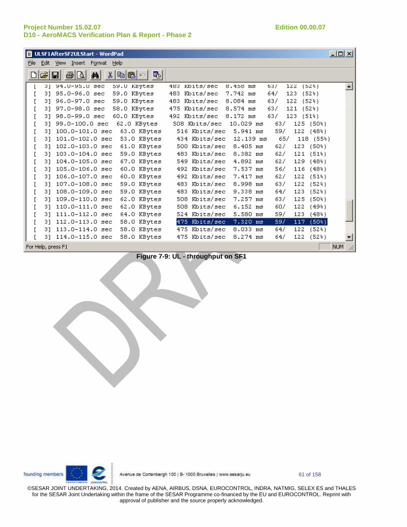
Project Number 15.02.07 Edition 00.00.07 D10 - AeroMACS Verification Plan & Report - Phase 2
61 of 158
©SESAR JOINT UNDERTAKING, 2014. Created by AENA, AIRBUS, DSNA, EUROCONTROL, INDRA, NATMIG, SELEX ES and THALES
for the SESAR Joint Undertaking within the frame of the SESAR Programme co-financed by the EU and EUROCONTROL. Reprint with approval of publisher and the source properly acknowledged.
Figure 7-9: UL - throughput on SF1

Project Number 15.02.07 Edition 00.00.07 D10 - AeroMACS Verification Plan & Report - Phase 2
62 of 158
©SESAR JOINT UNDERTAKING, 2014. Created by AENA, AIRBUS, DSNA, EUROCONTROL, INDRA, NATMIG, SELEX ES and THALES
for the SESAR Joint Undertaking within the frame of the SESAR Programme co-financed by the EU and EUROCONTROL. Reprint with approval of publisher and the source properly acknowledged.
Figure 7-10: UL - throughput on SF2
Subsequently, the Traffic Priority of Service Flow #2 was increased with respect to SF1, and the MS was restarted; the same tests done before in DL and UL were repeated. This time, a reversal of results was observed, both in DL and UL: in fact this time, thanks to the SF2 higher priority, its throughput got higher, to the detriment of SF1 throughput (and despite of the lower MSTR2 threshold). Figure 7-11 shows the DL case.
The tests were repeated with different Scheduling Types (rtps, e-rtps, nrtps), giving similar results.

Project Number 15.02.07 Edition 00.00.07 D10 - AeroMACS Verification Plan & Report - Phase 2
63 of 158
©SESAR JOINT UNDERTAKING, 2014. Created by AENA, AIRBUS, DSNA, EUROCONTROL, INDRA, NATMIG, SELEX ES and THALES
for the SESAR Joint Undertaking within the frame of the SESAR Programme co-financed by the EU and EUROCONTROL. Reprint with approval of publisher and the source properly acknowledged.
Figure 7-11: SF2 with higher priority
A.1.3.3.3 Unexpected behaviors/results
None
A.1.3.4 Conclusions and recommendations
The testing allowed verifying that all QoS related requirements are satisfied for different Scheduling Types and for different traffic priorities, in both directions.

Project Number 15.02.07 Edition 00.00.07 D10 - AeroMACS Verification Plan & Report - Phase 2
64 of 158
©SESAR JOINT UNDERTAKING, 2014. Created by AENA, AIRBUS, DSNA, EUROCONTROL, INDRA, NATMIG, SELEX ES and THALES
for the SESAR Joint Undertaking within the frame of the SESAR Programme co-financed by the EU and EUROCONTROL. Reprint with approval of publisher and the source properly acknowledged.
A.1.4 Verification Exercise # P2_LAB1_4 Security
A.1.4.1 Verification Exercise Scope
Scope of this test is to verify that after Authentication, Data are properly encrypted, according to the required Private Key Management Protocol.
A.1.4.2 Conduct of Verification Exercise
A.1.4.2.1 Verification Exercise Preparation The test bed described in Figure 3-2 was used, except the Spectrum Analyser/Signal Generator and Fading Simulator, which were not needed in this test.
A.1.4.2.2 Verification Exercise execution
Step nr. Action Action description PCO (Point of Control
and Observation)
Result
1. Switch on MS OK
2. Switch on BS and ASN-
GW/AAA
OK
3. Establish a communication and verify that the EAP based authentication method is supported:
With Authentication
enabled, valid
credentials inserted
R6 i/f with
wireshark
OK
4. Verify that the used PKM
protocol is PKMv2
Authentication has
been previously
enabled
Internal log OK
5. Verify that all the
Encrypted Data Traffic is
correctly sent and
received without errors
due to the application of
the Encryption procedure
Internal log OK
6. Verify re-authentication Forced re-
authentication on the
ASN-GW/AAA
R6 i/f with
wireshark
OK

Project Number 15.02.07 Edition 00.00.07 D10 - AeroMACS Verification Plan & Report - Phase 2
65 of 158
©SESAR JOINT UNDERTAKING, 2014. Created by AENA, AIRBUS, DSNA, EUROCONTROL, INDRA, NATMIG, SELEX ES and THALES
for the SESAR Joint Undertaking within the frame of the SESAR Programme co-financed by the EU and EUROCONTROL. Reprint with approval of publisher and the source properly acknowledged.
A.1.4.2.3 Deviation from the planned activities
None.
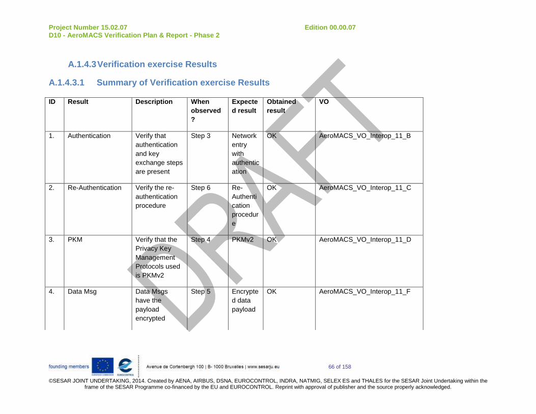
Project Number 15.02.07 Edition 00.00.07 D10 - AeroMACS Verification Plan & Report - Phase 2
66 of 158
©SESAR JOINT UNDERTAKING, 2014. Created by AENA, AIRBUS, DSNA, EUROCONTROL, INDRA, NATMIG, SELEX ES and THALES for the SESAR Joint Undertaking within the
frame of the SESAR Programme co-financed by the EU and EUROCONTROL. Reprint with approval of publisher and the source properly acknowledged.
A.1.4.3 Verification exercise Results
A.1.4.3.1 Summary of Verification exercise Results
ID Result Description When
observed
?
Expecte
d result
Obtained
result
VO
1. Authentication Verify that
authentication
and key
exchange steps
are present
Step 3 Network
entry
with
authentic
ation
OK AeroMACS_VO_Interop_11_B
2. Re-Authentication Verify the re-
authentication
procedure
Step 6 Re-
Authenti
cation
procedur
e
OK AeroMACS_VO_Interop_11_C
3. PKM Verify that the
Privacy Key
Management
Protocols used
is PKMv2
Step 4 PKMv2 OK AeroMACS_VO_Interop_11_D
4. Data Msg Data Msgs
have the
payload
encrypted
Step 5 Encrypte
d data
payload
OK AeroMACS_VO_Interop_11_F

Project Number 15.02.07 Edition 00.00.07 D10 - AeroMACS Verification Plan & Report - Phase 2
67 of 158
©SESAR JOINT UNDERTAKING, 2014. Created by AENA, AIRBUS, DSNA, EUROCONTROL, INDRA, NATMIG, SELEX ES and THALES
for the SESAR Joint Undertaking within the frame of the SESAR Programme co-financed by the EU and EUROCONTROL. Reprint with approval of publisher and the source properly acknowledged.
A.1.4.3.2 Analysis of Verification Exercise Results The ASN-GW was configured in order to require Authentication to the MS entering the Network; BS and MS were switched on, and the MS started the Net Entry procedure, that was completed successfully. Concerning the Authentication procedure, Wireshark log in Figure 7-12 shows the “Client Hello” message sent by the BS (125.125.40.32, on behalf of the MS) to the ASN-GW (125.125.40.48) starting the Handshake for Authentication, In particular the picture shows the Cipher Suites supported by the MS. The ASN-GW will then select one of the supported suites in a subsequent “Server Hello” message, containing also the BS Certificate (see Figure 7-13). So it is possible to see that the MS and BS negotiate the AES128 Encryption method for data plane.
Figure 7-12: Cipher Suites supported by MS

Project Number 15.02.07 Edition 00.00.07 D10 - AeroMACS Verification Plan & Report - Phase 2
68 of 158
©SESAR JOINT UNDERTAKING, 2014. Created by AENA, AIRBUS, DSNA, EUROCONTROL, INDRA, NATMIG, SELEX ES and THALES
for the SESAR Joint Undertaking within the frame of the SESAR Programme co-financed by the EU and EUROCONTROL. Reprint with approval of publisher and the source properly acknowledged.
Figure 7-13: "Server Hello" from ASN-GW After the successful MS authentication, the subsequent phase of Registration started. It is possible to observe in Figure 7-14 that the PKMv2 is used. From this point on, all of the Data exchanged between BS and MS were cyphered, and the proper reception at the addressee was observed. After the expiration of the AK Lifetime timer, the proper Re-Authentication was observed.

Project Number 15.02.07 Edition 00.00.07 D10 - AeroMACS Verification Plan & Report - Phase 2
69 of 158
©SESAR JOINT UNDERTAKING, 2014. Created by AENA, AIRBUS, DSNA, EUROCONTROL, INDRA, NATMIG, SELEX ES and THALES
for the SESAR Joint Undertaking within the frame of the SESAR Programme co-financed by the EU and EUROCONTROL. Reprint with approval of publisher and the source properly acknowledged.
Figure 7-14: Privacy Key Management Protocol

Project Number 15.02.07 Edition 00.00.07 D10 - AeroMACS Verification Plan & Report - Phase 2
70 of 158
©SESAR JOINT UNDERTAKING, 2014. Created by AENA, AIRBUS, DSNA, EUROCONTROL, INDRA, NATMIG, SELEX ES and THALES
for the SESAR Joint Undertaking within the frame of the SESAR Programme co-financed by the EU and EUROCONTROL. Reprint with approval of publisher and the source properly acknowledged.
Figure 7-15: First cyphered messages after Authentication: DHCP
A.1.4.4 Conclusions and recommendations It was verified that, after Authentication, Data are properly encrypted, according to the required Private Key Management Protocol.
A.1.5 Verification Exercise # P2_LAB1_5 Radio Characteristic Requirements
A.1.5.1 Verification Exercise Scope Scope of this Test is to estimate the tolerated co-channel OFDMA signal and the capability to recover and operate correctly when the co-channel is removed.
A.1.5.2 Conduct of Verification Exercise
A.1.5.2.1 Verification Exercise Preparation
The test bed described in Figure 3-2 was arranged.
A.1.5.2.2 Verification Exercise execution
Step
nr.
Action Action description
(if needed)
PCO (Point of Control
and Observation)
Result
1. Switch on MS OK
2. Switch on BS (BS1) BS switched on with
PTX = 30 dBm
OK
3. Verify the frequency filter
for each channel of the
BS prototype
OK
4. Verify that MS connects
successfully
Mngt PCs
connected to MS
and BS
OK
5. Measure RSSI level
received at MS
Mngt PCs
connected to MS
OK
6. Switch on the interfering
device at the same
frequency as MS/BS,
applying the maximum
As BS2 TX power is
equal to 30 dBm, an
initial attenuation
equal to 130 dB
Use another BS
(BS2)
OK
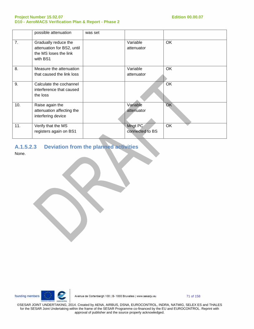
Project Number 15.02.07 Edition 00.00.07 D10 - AeroMACS Verification Plan & Report - Phase 2
71 of 158
©SESAR JOINT UNDERTAKING, 2014. Created by AENA, AIRBUS, DSNA, EUROCONTROL, INDRA, NATMIG, SELEX ES and THALES
for the SESAR Joint Undertaking within the frame of the SESAR Programme co-financed by the EU and EUROCONTROL. Reprint with approval of publisher and the source properly acknowledged.
possible attenuation was set
7. Gradually reduce the
attenuation for BS2, until
the MS loses the link
with BS1
Variable
attenuator
OK
8. Measure the attenuation
that caused the link loss
Variable
attenuator
OK
9. Calculate the cochannel
interference that caused
the loss
OK
10. Raise again the
attenuation affecting the
interfering device
Variable
attenuator
OK
11. Verify that the MS
registers again on BS1
Mngt PC
connected to BS
OK
A.1.5.2.3 Deviation from the planned activities
None.

Project Number 15.02.07 Edition 00.00.07 D10 - AeroMACS Verification Plan & Report - Phase 2
72 of 158
©SESAR JOINT UNDERTAKING, 2014. Created by AENA, AIRBUS, DSNA, EUROCONTROL, INDRA, NATMIG, SELEX ES and THALES for the SESAR Joint Undertaking within the
frame of the SESAR Programme co-financed by the EU and EUROCONTROL. Reprint with approval of publisher and the source properly acknowledged.
A.1.5.3 Verification exercise Results
A.1.5.3.1 Summary of Verification exercise Results
ID Result Description When
observed?
Expected
result
Obtained
result
VO
1 Frequency filter Verify the
frequency filter
for each
channel of the
BS prototype
Step 3 Measurement
of the
frequency filter
for each
channel
OK AeroMACS_VO_RFReal_01_B
2 Co-Channel Test the
tolerated co-
channel
OFDMA signal
Step 9 Co-channel
rejection
capability OK
AeroMACS_VO_RF_04_A

Project Number 15.02.07 Edition 00.00.07 D10 - AeroMACS Verification Plan & Report - Phase 2
73 of 158
©SESAR JOINT UNDERTAKING, 2014. Created by AENA, AIRBUS, DSNA, EUROCONTROL, INDRA, NATMIG, SELEX ES and THALES
for the SESAR Joint Undertaking within the frame of the SESAR Programme co-financed by the EU and EUROCONTROL. Reprint with approval of publisher and the source properly acknowledged.
A.1.5.3.2 Analysis of Verification Exercise Results
The frequency filter for each channel of the BS prototype was verified. Figure 7-16 shows an example for the 5113.5 MHz channel.
Figure 7-16: Frequency filter at 5113.5 MHz
Then, the MS was switched on and executed the complete Net Entry. The received power level received by the MS was measured as -70 dBm. (BS1 TX Power = 30 dBm and total attenuation = 100 dB).
All the steps described in A.1.5.2.2 were executed, and it was verified that the MS lost the link when the attenuation affecting BS2 transmission was 10 dB lower than the one affecting BS1 transmission. This indicated a co-channel rejection capability estimate equal to 10 dB.
A.1.5.3.3 Unexpected behaviors/results
None
A.1.5.4 Conclusions and recommendations The testing allowed proper estimation of the tolerated co-channel OFDMA signal and the capability to recover and operate correctly when the co-channel is removed.

Project Number 15.02.07 Edition 00.00.07 D10 - AeroMACS Verification Plan & Report - Phase 2
74 of 158
©SESAR JOINT UNDERTAKING, 2014. Created by AENA, AIRBUS, DSNA, EUROCONTROL, INDRA, NATMIG, SELEX ES and THALES
for the SESAR Joint Undertaking within the frame of the SESAR Programme co-financed by the EU and EUROCONTROL. Reprint with approval of publisher and the source properly acknowledged.
A.1.6 Verification Exercise # P2_LAB1_6 Limited IOT Requirements
A.1.6.1 Verification Exercise Scope
The scope of this Exercise is verifying basic interoperability capability between prototypes from Selex ES and Thales. The verification scenario in this section is limited to one BS with a static MS to check that the various steps of the Initial Network Entry are properly executed.
A.1.6.2 Conduct of Verification Exercise
A.1.6.2.1 Verification Exercise Preparation
The Test Bed used in the SELEX ES Labs for the Air Interface Limited Interoperability Tests is the same reported in Figure 3-2, in which the Mobile Station was a Thales Mobile Station. In particular:
- the ASN-GW used was a COTS Aricent Wing 4.2.0 ASN-GW, compatible with WMF NWG 1.2.
- the AAA Server used was FreeRADIUS 2.1.3.1 (see [4] for details).
- Wireshark 1.8.6 was used to monitor the messages exchange between the Thales MS and the ASN-GW/AAA Server
A.1.6.2.2 Verification Exercise execution
Step
nr.
Action Action description
(if needed)
PCO (Point of Control
and Observation)
Result
1. Switch on MS
2. Switch on BS
3. Verify that MS starts off with the scanning of the spectrum. Verify that the correct
expected broadcast
messages are
exchanged, and the
preamble is correctly
decoded by the MS.
Mngt PCs
connected to MS
and BS
OK
4. Verify that, after
successful DL
Synchronization, MS and
BS exchanges the
proper RNG-REQ/RNG-
RSP messages,
completing the Initial
Ranging
Mngt PCs
connected to MS
and BS
OK

Project Number 15.02.07 Edition 00.00.07 D10 - AeroMACS Verification Plan & Report - Phase 2
75 of 158
©SESAR JOINT UNDERTAKING, 2014. Created by AENA, AIRBUS, DSNA, EUROCONTROL, INDRA, NATMIG, SELEX ES and THALES
for the SESAR Joint Undertaking within the frame of the SESAR Programme co-financed by the EU and EUROCONTROL. Reprint with approval of publisher and the source properly acknowledged.
5. Verify the correct
exchange of Service
Basic Capability
informations
Mngt PCs
connected to MS
and BS
OK
6. Verify the Security
associations and key
exchange that concern
only to the "air interface"
as part of the MS
Authentication and
Authorization procedures
Mngt PCs
connected to MS
and BS
NOK
7. Verify that BS and MS
successfully conclude
the registration
procedure
Mngt PCs
connected to MS
and BS
NT
A.1.6.2.3 Deviation from the planned activities It was not possible to complete the last step of the test: step number 7 above as authentication/authorization in step 6 failed. The reasons for the MS Certificate Authentication failure by the AAA Server were investigated by Selex ES and Thales teams, for more information about the results of this investigation refer to A.1.6.3.3.

Project Number 15.02.07 Edition 00.00.07 D10 - AeroMACS Verification Plan & Report - Phase 2
76 of 158
©SESAR JOINT UNDERTAKING, 2014. Created by AENA, AIRBUS, DSNA, EUROCONTROL, INDRA, NATMIG, SELEX ES and THALES for the SESAR Joint Undertaking within the
frame of the SESAR Programme co-financed by the EU and EUROCONTROL. Reprint with approval of publisher and the source properly acknowledged.
A.1.6.3 Verification exercise Results
A.1.6.3.1 Summary of Verification exercise Results
ID Result Description When
observed?
Expected result Obtained result VO
1 Scanning and
synchronization
Verify that
scanning and
synchronization
are correctly
performed
Step 3 Synchronization OK AeroMACS_VO_Limited
Interop_A
2 Initial Ranging Verify that Initial
Ranging is
correctly
performed
Step 4 Initial ranging
executed
OK AeroMACS_VO_Limited
Interop_B
3 Basic Capabilities
Negotiation
Verify the correct
exchange of SBC
information
Step 5 SBC_REQ/SBC
_RSP properly
exchanged
OK AeroMACS_VO_Limited
Interop_C
4 Admission control Verify that
Authentication
and Authorization
procedures are
correctly
executed on MS
and BS side
Step 6 Verify that MS
is authenticated
by the Ground
System
NOK AeroMACS_VO_Limited
Interop_D
5 Registration Verify that BS
and MS
successfully
Step 7 Verify that BS
and MS
successfully
NT AeroMACS_VO_Limited
Interop_E

Project Number 15.02.07 Edition 00.00.07 D10 - AeroMACS Verification Plan & Report - Phase 2
77 of 158
©SESAR JOINT UNDERTAKING, 2014. Created by AENA, AIRBUS, DSNA, EUROCONTROL, INDRA, NATMIG, SELEX ES and THALES for the SESAR Joint Undertaking within the
frame of the SESAR Programme co-financed by the EU and EUROCONTROL. Reprint with approval of publisher and the source properly acknowledged.
conclude the
registration
procedure
conclude the
registration
procedure
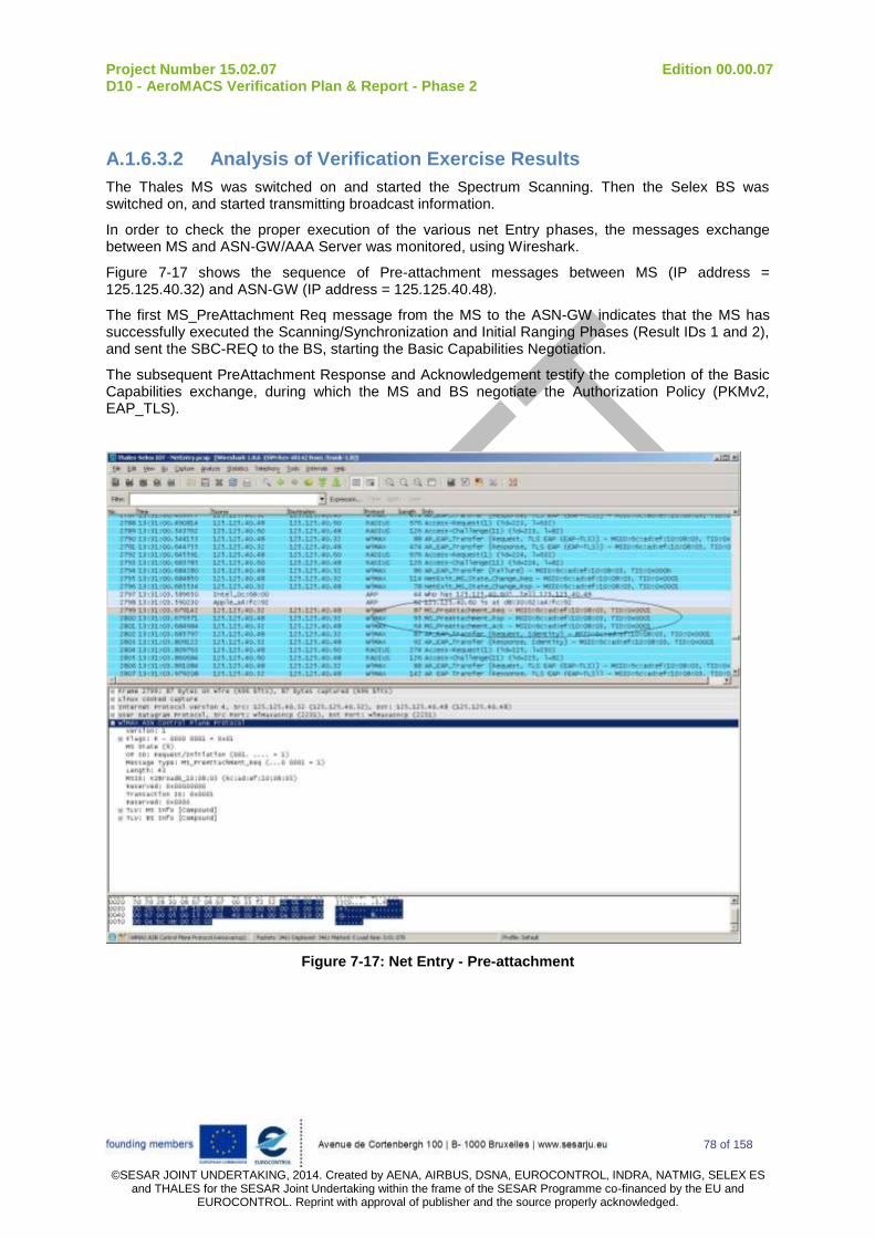
Project Number 15.02.07 Edition 00.00.07 D10 - AeroMACS Verification Plan & Report - Phase 2
78 of 158
©SESAR JOINT UNDERTAKING, 2014. Created by AENA, AIRBUS, DSNA, EUROCONTROL, INDRA, NATMIG, SELEX ES
and THALES for the SESAR Joint Undertaking within the frame of the SESAR Programme co-financed by the EU and EUROCONTROL. Reprint with approval of publisher and the source properly acknowledged.
A.1.6.3.2 Analysis of Verification Exercise Results
The Thales MS was switched on and started the Spectrum Scanning. Then the Selex BS was switched on, and started transmitting broadcast information.
In order to check the proper execution of the various net Entry phases, the messages exchange between MS and ASN-GW/AAA Server was monitored, using Wireshark.
Figure 7-17 shows the sequence of Pre-attachment messages between MS (IP address = 125.125.40.32) and ASN-GW (IP address = 125.125.40.48).
The first MS_PreAttachment Req message from the MS to the ASN-GW indicates that the MS has successfully executed the Scanning/Synchronization and Initial Ranging Phases (Result IDs 1 and 2), and sent the SBC-REQ to the BS, starting the Basic Capabilities Negotiation.
The subsequent PreAttachment Response and Acknowledgement testify the completion of the Basic Capabilities exchange, during which the MS and BS negotiate the Authorization Policy (PKMv2, EAP_TLS).
Figure 7-17: Net Entry - Pre-attachment

Project Number 15.02.07 Edition 00.00.07 D10 - AeroMACS Verification Plan & Report - Phase 2
79 of 158
©SESAR JOINT UNDERTAKING, 2014. Created by AENA, AIRBUS, DSNA, EUROCONTROL, INDRA, NATMIG, SELEX ES
and THALES for the SESAR Joint Undertaking within the frame of the SESAR Programme co-financed by the EU and EUROCONTROL. Reprint with approval of publisher and the source properly acknowledged.
Subsequently, the Authentication procedure started. The MS sent its Identity (NAI) by means of a PKMv2-REQ message to the BS, which forwarded it to the ASN-GW by means of a AuthRelay_EAP_Transfer_Response message (packet n° 2803 in Figure 7-18).
The Identity was then forwarded to the AAA-Server (IP address = 125.125.40.60) for its acceptance, that happened properly (packet n°2805 in Figure 7-18).
Figure 7-18: Authentication - MS Identity Acceptance
Once the MS Identity was accepted by the AAA Server, the ASN-GW sent a "Server Hello" EAP-TLS Request towards the MS, containing the AAA Server Certificate and asking for the MS Certificate (packet n°2810 in Figure 7-19).
The MS sent an EAP_Response containing its Certificate (packet n°2821 in Figure 7-19).

Project Number 15.02.07 Edition 00.00.07 D10 - AeroMACS Verification Plan & Report - Phase 2
80 of 158
©SESAR JOINT UNDERTAKING, 2014. Created by AENA, AIRBUS, DSNA, EUROCONTROL, INDRA, NATMIG, SELEX ES
and THALES for the SESAR Joint Undertaking within the frame of the SESAR Programme co-financed by the EU and EUROCONTROL. Reprint with approval of publisher and the source properly acknowledged.
Figure 7-19: Authentication – Certificates exchange
At this point, after a conversation with the AAA-Server, the ASN-GW answered for 6 times with an Alert message, the MS tried for 6 other times to re-send the certificate, until at packet n°2848 in Figure 7-20 the ASN-GW answered with an Authentication Failure. (This behavior is compliant with RFC5216). The Net Exit was then executed.

Project Number 15.02.07 Edition 00.00.07 D10 - AeroMACS Verification Plan & Report - Phase 2
81 of 158
©SESAR JOINT UNDERTAKING, 2014. Created by AENA, AIRBUS, DSNA, EUROCONTROL, INDRA, NATMIG, SELEX ES
and THALES for the SESAR Joint Undertaking within the frame of the SESAR Programme co-financed by the EU and EUROCONTROL. Reprint with approval of publisher and the source properly acknowledged.
Figure 7-20: Authentication – Net Exit
A.1.6.3.3 Unexpected behaviors/results
The MS Certificate Authentication failure by the AAA Server was investigated by Selex ES and Thales teams, and it was not possible to identify a definitive reason.
One difference noted between the two implementations is that the Thales Ground System and MS Certificate were compliant to a FreeRADIUS version 1.1.7, while the AAA Server used by Selex ES was a FreeRADIUS 2.1.3.1. This could imply differences in the expected MS Certificates, or differences in some expected messages formats (e.g. the AR_EAP_Transfer_Response message sent by the Thales MS and refused by the Selex AAA Server).
Further investigations are recommended, to reach an unambiguous conclusion, using these indications as starting point.
A.1.6.4 Conclusions and recommendations
The testing allowed checking successfully the messages exchanges between BS and MS concerning the phases of Scanning, Synchronization, Initial Ranging, and Basic Capabilities Negotiation. The Authentication failed, and it was not possible to identify a definitive reason. However some useful indications were identified and described in the previous chapters. They can be used as starting point for further investigations.
There are currently discussions ongoing among various standardization Authorities (ICAO, WMF, EUROCAE, RTCA) about the security framework necessary for AeroMACS. There is the need to define a clear Certification Authority scheme, which is required in order to be able to use AeroMACS
Project Number 15.02.07 Edition 00.00.07 D10 - AeroMACS Verification Plan & Report - Phase 2
82 of 158
©SESAR JOINT UNDERTAKING, 2014. Created by AENA, AIRBUS, DSNA, EUROCONTROL, INDRA, NATMIG, SELEX ES
and THALES for the SESAR Joint Undertaking within the frame of the SESAR Programme co-financed by the EU and EUROCONTROL. Reprint with approval of publisher and the source properly acknowledged.
on a worldwide basis. The results of this test confirm also the need to identify unambiguously the WiMAX network protocols and messages formatting related to Authentication/Encryption.
It is suggested to plan ad-hoc activities with this purpose in the near future (SESAR2020/VLD could be suitable opportunities), to be conducted in strict coordination with the relevant standardization Authorities.

Project Number 15.02.07 Edition 00.00.07 D10 - AeroMACS Verification Plan & Report - Phase 2
83 of 158
©SESAR JOINT UNDERTAKING, 2014. Created by AENA, AIRBUS, DSNA, EUROCONTROL, INDRA, NATMIG, SELEX ES
and THALES for the SESAR Joint Undertaking within the frame of the SESAR Programme co-financed by the EU and EUROCONTROL. Reprint with approval of publisher and the source properly acknowledged.
A.2 Thales lab verification exercises
A.2.1 Verification Exercise # TLAB2_010
A.2.1.1 Verification Exercise Scope Test Service flow control: Verify the completion of the control messages to successfully complete the creation, change and deletion of a service flow to the MS.
A.2.1.2 Conduct of Verification Exercise
A.2.1.2.1 Verification Exercise Preparation Lab-test_bed_01 is prepared.
A.2.1.2.2 Verification Exercise execution
Step action Action result PCO Result
1 Set frequency on the GS :
- 5093,5 MHz
Provision new RF parameter on the GS
New frequency provisioned on GS
GS control MMI
Spectrum analyzer
OK
2 Set frequency scan of MS :
- 5093,5 MHz
- 5098,5 MHz
- 50103,5 MHz
MS connects eventually to the GS
GS control MMI OK
3 Attenuators are tuned to get a high modulation rate (16QAM3/4)
Initiate traffic in the DL thanks to the traffic generator (Iperf):
Datarate 5 Mbps
Communication established
Iperf OK
4 Create a new SF: BE with a max datarate of 300 kbps which is far below generated data throughput
A new SF is created GS control MMI OK
5 Allocate SF to MS and verify that it is dynamically taken into account
Datarate goes down to 300 kbps
Iperf OK
6 Delete SF and verify that it is dynamically taken into account
Datarate goes back to 5 Mbps
Iperf OK
A.2.1.2.3 Deviation from the planned activities
None.

Project Number 15.02.07 Edition 00.00.07 D10 - AeroMACS Verification Plan & Report - Phase 2
84 of 158
©SESAR JOINT UNDERTAKING, 2014. Created by AENA, AIRBUS, DSNA, EUROCONTROL, INDRA, NATMIG, SELEX ES
and THALES for the SESAR Joint Undertaking within the frame of the SESAR Programme co-financed by the EU and EUROCONTROL. Reprint with approval of publisher and the source properly acknowledged.
A.2.1.3 Verification exercise Results
A.2.1.3.1 Summary of Verification exercise Results
The SF change is dynamically allocated to the MS and the data traffic is transmitted via the created connection. After SF deletion the data traffic is no more sent on its connection. Hence, the SF creation change and deletion are successfully completed.
A.2.1.3.2 Analysis of Verification Exercise Results
Below, we put some details on the test execution. The screenshot from iperf server which is located on a PC connected to MS are shown.
One can see that first the data rate is around 5 Mbps which is compliant to what is sent and the default SF that is initially set.
Then the SF that limits the max data rate to 300 kbps is applied. One can see that the data rate received by iperf goes down and stabilizes at the 300 kbps limit.
Then the SF is deleted and the data rate goes back to 5 Mbps.
Figure 7-21: TLAB2_010 iperf screenshot

Project Number 15.02.07 Edition 00.00.07 D10 - AeroMACS Verification Plan & Report - Phase 2
85 of 158
©SESAR JOINT UNDERTAKING, 2014. Created by AENA, AIRBUS, DSNA, EUROCONTROL, INDRA, NATMIG, SELEX ES
and THALES for the SESAR Joint Undertaking within the frame of the SESAR Programme co-financed by the EU and EUROCONTROL. Reprint with approval of publisher and the source properly acknowledged.
A.2.1.3.3 Unexpected behaviors/Results
None
A.2.1.4 Conclusions and recommendations
The creation, change and deletion of a service flow to the MS have been successfully verified.

Project Number 15.02.07 Edition 00.00.07 D10 - AeroMACS Verification Plan & Report - Phase 2
86 of 158
©SESAR JOINT UNDERTAKING, 2014. Created by AENA, AIRBUS, DSNA, EUROCONTROL, INDRA, NATMIG, SELEX ES
and THALES for the SESAR Joint Undertaking within the frame of the SESAR Programme co-financed by the EU and EUROCONTROL. Reprint with approval of publisher and the source properly acknowledged.
A.2.2 Verification Exercise # TLAB2_020
A.2.2.1 Verification Exercise Scope Test channel selectivity and transmit power measurements: Verify the receiver adjacent channel selectivity, verify the BS/MS transmission mask in terms of adjacent and non-adjacent channel interferences, verify the BS output power to assess OFDMA crest factor.
A.2.2.2 Conduct of Verification Exercise
A.2.2.2.1 Verification Exercise Preparation Lab-test_bed_01 is prepared with an additional signal generator to simulate the interfering signal on adjacent and alternate channel.
Figure 7-22: test bed configuration with a signal generator
A.2.2.2.2 Verification Exercise execution
See also IEEE 802.16-2009 § 8.3.11.2 “Receiver adjacent and alternate channel rejection”.
Step action Action result PCO Result
Phase 1 Adjacent and non-adjacent channel leakage ratio
1 Set frequency on the GS :
- 5093,5 MHz
Provision new RF parameter on the GS
New frequency provisioned on GS
GS control MMI
Spectrum analyzer
OK
2 Set frequency scan of MS :
- 5093,5 MHz
- 5098,5 MHz
- 5103,5 MHz
MS connects eventually to the GS
GS control MMI OK
3 Initiate traffic through the traffic generator (Iperf)
Communication established
Iperf OK
4 Measure through spectrum analyzer adjacent and alternate channel leakage
Spectrum Analyzer ACPR menu selected
Spectrum OK

Project Number 15.02.07 Edition 00.00.07 D10 - AeroMACS Verification Plan & Report - Phase 2
87 of 158
©SESAR JOINT UNDERTAKING, 2014. Created by AENA, AIRBUS, DSNA, EUROCONTROL, INDRA, NATMIG, SELEX ES
and THALES for the SESAR Joint Undertaking within the frame of the SESAR Programme co-financed by the EU and EUROCONTROL. Reprint with approval of publisher and the source properly acknowledged.
ration of MS and BS and spectrum measurement done
Analyzer
Phase 2 ACS (Receiver adjacent channel selectivity)
1 Set frequency on the GS :
- 5093,5 MHz
Fix modulation to 64QAM3/4
Provision new RF parameter on the GS
New frequency provisioned on GS
GS control MMI
Spectrum analyzer
OK
2 Set frequency scan of MS :
- 5093,5 MHz
- 5098,5 MHz
- 5103,5 MHz
MS connects eventually to the GS
GS control MMI OK
3 Initiate traffic through the traffic generator (Iperf)
Communication established
Iperf OK
4 Increase attenuation to set the signal’s strength close to the rate dependent receiver sensitivity (+3 dB)
Attenuator tuned Iperf
OK
5 Generate the interfering signal on adjacent channel.
Raise its power level until the error rate is obtained.
Note down the difference between the interfering signal and the desired channel: it is the corresponding adjacent channel rejection.
Adjacent Channel rejection characterized for 64QAM3/4
Spectrum Analyzer
Iperf
OK
6 Generate the interfering signal on alternate channel.
Raise its power level until the error rate is obtained.
Note down the difference between the interfering signal and the desired channel: it is the corresponding adjacent channel rejection.
Alternate Channel rejection characterized for 64QAM3/4
Spectrum Analyzer
OK
7 Fix modulation to 16QAM3/4
And redo step 3, 4, 5, and 6
Adjacent Channel rejection characterized for 16QAM3/4
Alternate Channel rejection characterized for 64QAM3/4
Spectrum Analyzer
OK
Phase 3 Crest factor measurement
1 Set frequency on the GS :
- 5093,5 MHz
Provision new RF parameter on the GS
New frequency provisioned on GS
GS control MMI
Spectrum analyzer
OK

Project Number 15.02.07 Edition 00.00.07 D10 - AeroMACS Verification Plan & Report - Phase 2
88 of 158
©SESAR JOINT UNDERTAKING, 2014. Created by AENA, AIRBUS, DSNA, EUROCONTROL, INDRA, NATMIG, SELEX ES
and THALES for the SESAR Joint Undertaking within the frame of the SESAR Programme co-financed by the EU and EUROCONTROL. Reprint with approval of publisher and the source properly acknowledged.
2 Set frequency scan of MS :
- 5093,5 MHz
- 5098,5 MHz
- 5103,5 MHz
MS connects eventually to the GS
GS control MMI OK
3 Initiate traffic through the traffic generator (Iperf)
Communication established
Iperf OK
4 Measure the crest factor on the spectrum analyzer
Measurement around 9 dB
Spectrum Analyzer
OK
A.2.2.2.3 Deviation from the planned activities
None.
A.2.2.3 Verification exercise Results
A.2.2.3.1 Summary of Verification exercise Results
Phase 1: ACLR
The measured adjacent and non-adjacent channel interference levels of GS / MS mask are given in table below:
Adjacent Channel Leakage Ratio of GS Mask Alternate Channel Leakage Ratio of GS Mask
-42 dB -51 dB
Adjacent Channel Leakage Ratio of MS Mask Alternate Channel Leakage Ratio of MS Mask
-44 dB -53 dB
Phase 2: ACS
The adjacent and alternate channel selectivity gives following results:
Modulation / coding Adjacent channel Rejection (dB)
/ limit in IEEE 802.16-2009 table 313 (dB)
Alternate channel Rejection (dB)
/ limit in IEEE standard 802.16-2009 table 313 (dB)
16 QAM ¾ 24 / 10 38 / 29
64 QAM ¾ 20 / 4 29 / 23
Phase 3: crest factor
The measured crest factor with traffic is about 9 dB, which corresponds to what is expected.

Project Number 15.02.07 Edition 00.00.07 D10 - AeroMACS Verification Plan & Report - Phase 2
89 of 158
©SESAR JOINT UNDERTAKING, 2014. Created by AENA, AIRBUS, DSNA, EUROCONTROL, INDRA, NATMIG, SELEX ES
and THALES for the SESAR Joint Undertaking within the frame of the SESAR Programme co-financed by the EU and EUROCONTROL. Reprint with approval of publisher and the source properly acknowledged.
A.2.2.3.2 Analysis of Verification Exercise Results
Phase 1: ACLR
Adjacent Channel Power Ratio (ACPR) or Adjacent Channel Leakage Ratio (ACLR) is a measure of the transmitter energy that is ‘leaking’ into an adjacent or alternate channel. Ideally, a transmitter could keep all of its transmitted energy in its assigned channel, but realistically some small amount of the transmitter energy will show up in other nearby channels. A spectrum analyzer is used to make this measurement: the first step is to measure the in-channel power; after this, the analyzer measures the frequency offset 1 channel away, and the ‘leakage’ power is measured as the difference in these two measurements (called ACP ratio or ACLR).
Below we see the result for the DL (values expressed in difference compared to central channel (TX)):
Below we see the result for the UL (values expressed in difference compared to central channel (TX)):

Project Number 15.02.07 Edition 00.00.07 D10 - AeroMACS Verification Plan & Report - Phase 2
90 of 158
©SESAR JOINT UNDERTAKING, 2014. Created by AENA, AIRBUS, DSNA, EUROCONTROL, INDRA, NATMIG, SELEX ES
and THALES for the SESAR Joint Undertaking within the frame of the SESAR Programme co-financed by the EU and EUROCONTROL. Reprint with approval of publisher and the source properly acknowledged.
Phase 2: ACS
The adjacent channel rejection and alternate channel rejection is measured by setting the desired signal’s strength above but close to (3 dB) the rate dependent receiver sensitivity and raising the power level of the interfering signal until the sensitivity specified error rate is obtained. The power difference between the interfering signal and the desired channel is the corresponding adjacent channel rejection.
The interfering signal in the adjacent or alternate channel is a conforming OFDMA signal, not synchronized with the signal in the channel under test but with same type of parameters: 5ms frame, 5MHz bandwidth.
The screenshot below from the spectrum analyser shows the spectrum of the signal under test (central) and the spectrum of the interfering signal either in adjacent channel or alternate channel. The difference between both signal power is highlighted.
64QAM ¾ case:

Project Number 15.02.07 Edition 00.00.07 D10 - AeroMACS Verification Plan & Report - Phase 2
91 of 158
©SESAR JOINT UNDERTAKING, 2014. Created by AENA, AIRBUS, DSNA, EUROCONTROL, INDRA, NATMIG, SELEX ES
and THALES for the SESAR Joint Undertaking within the frame of the SESAR Programme co-financed by the EU and EUROCONTROL. Reprint with approval of publisher and the source properly acknowledged.
16 QAM ¾ case:

Project Number 15.02.07 Edition 00.00.07 D10 - AeroMACS Verification Plan & Report - Phase 2
92 of 158
©SESAR JOINT UNDERTAKING, 2014. Created by AENA, AIRBUS, DSNA, EUROCONTROL, INDRA, NATMIG, SELEX ES
and THALES for the SESAR Joint Undertaking within the frame of the SESAR Programme co-financed by the EU and EUROCONTROL. Reprint with approval of publisher and the source properly acknowledged.
We can see the 16QAM3/4 is more robust than the 64QAM3/4 by around 7 dB which is what was expected.

Project Number 15.02.07 Edition 00.00.07 D10 - AeroMACS Verification Plan & Report - Phase 2
93 of 158
©SESAR JOINT UNDERTAKING, 2014. Created by AENA, AIRBUS, DSNA, EUROCONTROL, INDRA, NATMIG, SELEX ES
and THALES for the SESAR Joint Undertaking within the frame of the SESAR Programme co-financed by the EU and EUROCONTROL. Reprint with approval of publisher and the source properly acknowledged.
Phase 3: Crest factor
The WiMAX option of our spectrum analyser directly computes the crest factor as one can see in following picture. The crest factor with data transmission active is around 9 dB, in conformance with what was expected.
A.2.2.3.3 Unexpected behaviors/Results
None.
A.2.2.4 Conclusions and recommendations
The prototypes present a good behaviour compared to what is expected in standard.

Project Number 15.02.07 Edition 00.00.07 D10 - AeroMACS Verification Plan & Report - Phase 2
94 of 158
©SESAR JOINT UNDERTAKING, 2014. Created by AENA, AIRBUS, DSNA, EUROCONTROL, INDRA, NATMIG, SELEX ES
and THALES for the SESAR Joint Undertaking within the frame of the SESAR Programme co-financed by the EU and EUROCONTROL. Reprint with approval of publisher and the source properly acknowledged.
A.2.3 Verification Exercise # TLAB2_030
A.2.3.1 Verification Exercise Scope MS channel quality report and MS transmit synchronisation Verify that MS channel quality report to BS and verify the MS transmitted centre frequency precision.
A.2.3.2 Conduct of Verification Exercise
A.2.3.2.1 Verification Exercise Preparation
Lab-test_bed_01 is prepared. Spectrum Analyzer is moved to replace MS in order to measure the actual received power of the MS
A.2.3.2.2 Verification Exercise execution
Step action Action result PCO Result
Phase 1 MS feedback to BS
1 Set frequency on the GS :
- 5093,5 MHz
Provision new RF parameter on the GS
New frequency provisioned on GS
GS control MMI
Spectrum analyzer
OK
2 Set frequency scan of MS :
- 5093,5 MHz
- 5098,5 MHz
- 5103,5 MHz
MS connects eventually to the GS
GS control MMI
OK
3 Initiate traffic through the traffic generator (Iperf)
Communication established Iperf OK
4 Measure through spectrum analyzer the received level at MS antenna port and compare with the RSSI measured by MS itself and received on BS
Measured level on Spectrum Analyzer
RSSI at MS
And BS side
Spectrum Analyzer
MS MMI
GS control MMI
OK
Phase 2 Central frequency measurement
1 Set frequency on the GS :
- 5093,5 MHz
Provision new RF parameter on the GS
New frequency provisioned on GS
GS control MMI
Spectrum analyzer
OK
2 Set frequency scan of MS :
- 5093,5 MHz
- 5098,5 MHz
- 5103,5 MHz
MS connects eventually to the GS
GS control MMI
OK
3 Initiate traffic through the traffic generator (Iperf)
Communication established Iperf OK
4 Measure through spectrum analyzer the central frequency of MS
Measured frequency on Spectrum Analyzer
Spectrum Analyzer
OK

Project Number 15.02.07 Edition 00.00.07 D10 - AeroMACS Verification Plan & Report - Phase 2
95 of 158
©SESAR JOINT UNDERTAKING, 2014. Created by AENA, AIRBUS, DSNA, EUROCONTROL, INDRA, NATMIG, SELEX ES
and THALES for the SESAR Joint Undertaking within the frame of the SESAR Programme co-financed by the EU and EUROCONTROL. Reprint with approval of publisher and the source properly acknowledged.
A.2.3.2.3 Deviation from the planned activities None.
A.2.3.3 Verification exercise Results
A.2.3.3.1 Summary of Verification exercise Results
Phase 1: Measured RSSI on the MS is in good correlation with measured power from the spectrum analyser. The RSSI transmitted by MS to the BS is good (1 dB rounding) except for RSSI above -40 dBm, as they are floored to -40 dBm on BS control MMI.
Phase 2: The measured centre frequency on the UL doesn’t deviate more than 2% of the subcarrier spacing compared to the BS center frequency.
A.2.3.3.2 Analysis of Verification Exercise Results
Phase 1: MS feedback
received Power
On Spectrum Analyzer
MS MMI BS control MMI
Att 1 TD Power DL preamble -56 dBm
Power DL Preamble -51 dBm
RSSI -54 dBm
RSSI -55 dBm
Att 2 TD Power DL preamble -46 dBm
Power DL Preamble -41 dBm
RSSI -44 dBm
RSSI -45 dBm
Att 3 TD Power DL preamble -36 dBm
Power DL Preamble -31 dBm
RSSI -34 dBm
RSSI -40 dBm
Att 4 TD Power DL preamble -26 dBm
Power DL Preamble -21 dBm
RSSI -24 dBm
RSSI -40 dBm
Att 5 - Non synchronized - RSSI -64 dBm RSSI -65 dBm
Att6 - Non synchronized - RSSI -75 dBm RSSI -76 dBm
Phase 2:
The measured centre frequency on the DL is : 5 093 464 737 Hz (5093,5 MHz – 35263,17 Hz)

Project Number 15.02.07 Edition 00.00.07 D10 - AeroMACS Verification Plan & Report - Phase 2
96 of 158
©SESAR JOINT UNDERTAKING, 2014. Created by AENA, AIRBUS, DSNA, EUROCONTROL, INDRA, NATMIG, SELEX ES
and THALES for the SESAR Joint Undertaking within the frame of the SESAR Programme co-financed by the EU and EUROCONTROL. Reprint with approval of publisher and the source properly acknowledged.
The center frequency of the Spectrum analyser is tuned to 5 093 464 737 Hz and the spectrum analyser is plugged in the UL to measured the MS spectrum.
The measured UL centre frequency is: 5 093 464 720 Hz (5 093 500 – 35279,74)
The subcarrier spacing is: 5 600 000 / 512 = 10937,5 Hz
2% of subcarrier spacing is: 219 Hz
The deviation of the MS centre frequency compared to the BS frequency divided by to the subcarrier spacing is < 2%: 5 093 464 737 - 5 093 464 720 = 17 Hz compared to 219 Hz
A.2.3.3.3 Unexpected behaviors/Results
The DL RSSI read on the BS control MMI is at maximum -40 dBm. This behaviour doesn’t prevent performing the outdoor testing as the DL RSSI is generally well below -40 dBm and the RSSI shown on MS MMI is correct.
A.2.3.4 Conclusions and recommendations
The testing allowed checking successfully the feedback of MS information to the BS and the MS centre frequency precision.
TX

Project Number 15.02.07 Edition 00.00.07 D10 - AeroMACS Verification Plan & Report - Phase 2
97 of 158
©SESAR JOINT UNDERTAKING, 2014. Created by AENA, AIRBUS, DSNA, EUROCONTROL, INDRA, NATMIG, SELEX ES
and THALES for the SESAR Joint Undertaking within the frame of the SESAR Programme co-financed by the EU and EUROCONTROL. Reprint with approval of publisher and the source properly acknowledged.
A.2.4 Verification Exercise # TLAB2_040
A.2.4.1 Verification Exercise Scope IOT testing Verify the interoperability of Selex MS with Thales GS over the air interface.
A.2.4.2 Conduct of Verification Exercise
A.2.4.2.1 Verification Exercise Preparation
Lab-test_bed_01 is prepared. Selex MS replaced Thales MS.
Figure 7-23: Selex MS in Thales lab (Baseband 1U rack below and RF 1U rack above)
A.2.4.2.2 Verification Exercise execution
Step Action Action result PCO Result
Phase 1
Set frequency on the GS :
- 5093,5 MHz
Provision new RF parameter on the GS
New frequency provisioned on GS
GS control MMI
Spectrum analyzer
OK
2 Set frequency scan of Selex MS :
- 5093,5 MHz
MS performs successive stages for registration:
Scanning / synchronization
Initial ranging
Basic capabilities negotiation
Admission control
Registration
And connects eventually to the GS
GS control MMI
pOK

Project Number 15.02.07 Edition 00.00.07 D10 - AeroMACS Verification Plan & Report - Phase 2
98 of 158
©SESAR JOINT UNDERTAKING, 2014. Created by AENA, AIRBUS, DSNA, EUROCONTROL, INDRA, NATMIG, SELEX ES
and THALES for the SESAR Joint Undertaking within the frame of the SESAR Programme co-financed by the EU and EUROCONTROL. Reprint with approval of publisher and the source properly acknowledged.
A.2.4.2.3 Deviation from the planned activities
Only the first step of the verification exercise could be successfully verified: scanning and preamble detection. It is noted that the testing session was held as planned during July in Thales lab with remote assistance of Selex team. Despite numerous attempts to identify the source of the problem, no improvement was achieved, and the test campaign was closed. A tentative second session was initially identified in September, but it was not possible to conduct it as the equipment could not finally be made available due to budget limitations and high activity in other AeroMACS related projects.
A.2.4.3 Verification exercise Results
A.2.4.3.1 Summary of Verification exercise Results
The results are:
Scanning / preamble detection => OK
Synchronization => NOK
Initial ranging => NT
Basic capabilities negotiation => NT
Admission control => NT
Registration => NT
A.2.4.3.2 Analysis of Verification Exercise Results
The Thales BS is switched on and starts transmitting broadcast information.
The Selex MS is switched on and starts the Spectrum Scanning.
Selex MS Logs indicate that the MS, after scanning, stops on the BS frequency and identifies the preamble sent by the BS: scanning and preamble detection is achieved.
After this first synchronization step, the MS logs indicate a “FCH decoding failed”, meaning that the MS doesn’t decode successfully the Frame Control Header (FCH) sent by the BS. As a result, synchronization is not finalized and the subsequent Network Entry phases are not executed.
During the tests, this situation was observed irrespectively of the value of attenuation inserted between MS and BS and various parameterizations.
A.2.4.3.3 Unexpected behaviors/Results
Only a part of this IOT is OK: scanning and preamble detection. Despite both Selex ES and Thales teams’ investigation efforts, it was not possible to demonstrate further interoperability in the frame of this test campaign.
A.2.4.4 Conclusions and recommendations
Only a small part of this interoperability testing is OK (additional IOT results can be found in A.1.6).
It is suggested to plan ad-hoc activities with the purpose to complete IOT in the near future (SESAR2020/VLD could be suitable opportunities) in coordination with the relevant standardization authorities.

Project Number 15.02.07 Edition 00.00.07 D10 - AeroMACS Verification Plan & Report - Phase 2
99 of 158
©SESAR JOINT UNDERTAKING, 2014. Created by AENA, AIRBUS, DSNA, EUROCONTROL, INDRA, NATMIG, SELEX ES
and THALES for the SESAR Joint Undertaking within the frame of the SESAR Programme co-financed by the EU and EUROCONTROL. Reprint with approval of publisher and the source properly acknowledged.
A.3 Thales Toulouse airport verification exercises
A.3.1 Introduction
Thanks to an appropriate preparation, the optimized test schedule is planned as follows:
Figure 7-24: Detailed Airport schedule Four Thales engineers were trained to have access to the Airport and Airport tests exercises were written and presented by THALES and then, analyzed and accepted by DSNA prior the testing period.
Install equipment(« pole mounting »)
DSNA
UninstallEquipment sent back
DSNA-> THALES
07/04 08/04 09/04 10/04 11/0431/03 14/04 15/04 16/04 17/04 18/04
SendTHALES
equipment
Access BadgesFinalize installation (IT)
TAIR_010
TAIR_020 TAIR_050
TAIR_030TAIR_040
Spare time
04/0403/0402/0401/04
week09 week13week12week11Week 10
Week 14 Week 15 Week 16
Indoor/outdoor tests to be prepared

Project Number 15.02.07 Edition 00.00.07 D10 - AeroMACS Verification Plan & Report - Phase 2
100 of 158
©SESAR JOINT UNDERTAKING, 2014. Created by AENA, AIRBUS, DSNA, EUROCONTROL, INDRA, NATMIG, SELEX ES
and THALES for the SESAR Joint Undertaking within the frame of the SESAR Programme co-financed by the EU and EUROCONTROL. Reprint with approval of publisher and the source properly acknowledged.
Figure 7-25: Training for Airport Clearance and test plan preparation (TAIR_10 up to TAIR_50)
Below, the results of the preparation phase before Toulouse Airport test campaign are summarized. Outdoor tests were performed in the vicinity of Thales premises in order to assess the behavior of the equipment in different propagation conditions that will be met at Toulouse: LOS, NLOS, and mobility. Two main setups were used:
- Installation in the countryside near Thales test premises near Paris: test up to 4 km in LOS.
Figure 7-26: Setup of the BS on a tower and MS on a truck for outdoor tests
- Installation in Thales premises Gennevilliers: test in NLOS and mobility, registration to the two
base stations. Furthermore, the testing software that records positions along with MS measurements (called survey tool) was also verified.
BS MS BS

Project Number 15.02.07 Edition 00.00.07 D10 - AeroMACS Verification Plan & Report - Phase 2
101 of 158
©SESAR JOINT UNDERTAKING, 2014. Created by AENA, AIRBUS, DSNA, EUROCONTROL, INDRA, NATMIG, SELEX ES
and THALES for the SESAR Joint Undertaking within the frame of the SESAR Programme co-financed by the EU and EUROCONTROL. Reprint with approval of publisher and the source properly acknowledged.
Figure 7-27: Outdoor tests in gennevilliers premises in NLOS
Figure 7-28: Outdoor tests in Gennevilliers @ 80 km/h
NLOS area 1
NLOS area 1
BS
NLOS area 2
NLOS area 3
90 km/h mobility
BS

Project Number 15.02.07 Edition 00.00.07 D10 - AeroMACS Verification Plan & Report - Phase 2
102 of 158
©SESAR JOINT UNDERTAKING, 2014. Created by AENA, AIRBUS, DSNA, EUROCONTROL, INDRA, NATMIG, SELEX ES
and THALES for the SESAR Joint Undertaking within the frame of the SESAR Programme co-financed by the EU and EUROCONTROL. Reprint with approval of publisher and the source properly acknowledged.
A.3.2 Verification Exercise # TAIR_010
A.3.2.1 Verification Exercise Scope Installation and Main performances verification on the field: 1) Install BS1 and BS2 in PB and fix MS in PA 2) Perform main AeroMACS performances measurements at fix MS point: Scanning, ranging, registration, throughput, QOS, mean power … 3) Install one MS in car.
BS1 on (BS2 off): perform a lap on the “route de service” (green below) and record MS RSSI on the fly
BS2 on (BS1 off): perform a lap again and record MS RSSI on the fly
A.3.2.2 Conduct of Verification Exercise
A.3.2.2.1 Verification Exercise Preparation
Equipment: BS1&2 + 1 fix MS + 1 MS in a car+ Spectrum Analyzer Resources:
- Thales: 2 engineers - DSNA: Required people for installation, one driver with a car.
Links and car trajectories: (the “route de service” will be used twice)
A.3.2.2.2 Verification Exercise execution
Step action Action result PCO Result
Phase 1 installation, scanning performance and successful completion of the ranging process
1 Install GS 1 and GS 2 as depicted in § 3.5.3.2
Orientation:
- BS1_TH : az 300° tilt : -3°
- BS2_TH : az 210° tilt : -3°
Take pictures of installation
GS started
GPS synchronized
Photos saved
GS control MMI
OK
2 GS2 is switched off.
Set frequency on the GS 1:
New frequency provisioned on GS
GS control MMI
OK

Project Number 15.02.07 Edition 00.00.07 D10 - AeroMACS Verification Plan & Report - Phase 2
103 of 158
©SESAR JOINT UNDERTAKING, 2014. Created by AENA, AIRBUS, DSNA, EUROCONTROL, INDRA, NATMIG, SELEX ES
and THALES for the SESAR Joint Undertaking within the frame of the SESAR Programme co-financed by the EU and EUROCONTROL. Reprint with approval of publisher and the source properly acknowledged.
- 5093,5 MHz
Provision new RF parameter on the GS 1
3 Install fix MS as depicted in § 3.5.3.3
Take pictures of installation
MS installed
MS accessed through its computer
Photos saved
MS Web interface
OK
4 Set frequency list of MS :
- 5093,5 MHz
- 5098,5 MHz
- 5103,5 MHz
MS connects eventually to the GS 1
F=5093,5 MHz
GS control MMI
MS web interface
OK
5 Initiate traffic in the UL or DL thanks to the traffic generator (Iperf)
Check RSSI on both side : MS and BS
Communication established in both directions (UL and DL)
Store information about RSSI / modulation
Iperf
BS/MS MMI
OK
-61 dBm
76 GS1 is switched off. GS2 is switched ON
Set frequency on the GS 2:
- 5103,5 MHz
Provision new RF parameter on the GS 2
New frequency provisioned on GS
GS control MMI
OK
7 Fix MS eventually connects to GS2 MS frequency 5103,5 MHz
Store information about RSSI / modulation
MS web interface
OK
-73 dBm
Phase 2 Lap on the Airport surface / fast coverage survey
1 GS 2 is switched OFF
GS 1 is switched ON
Switch off MS 1
Install MS 2 in a DSNA car
Switch ON MS2
Take pictures of installation
Set frequency list of MS 2 :
- 5093,5 MHz
- 5098,5 MHz
- 5103,5 MHz
MS 2 connects eventually to the GS 1
F=5093,5 MHz
Photos saved
GS control MMI
MS web interface
OK
2 Perform a lap on the “route de service” (green road on previous picture) and record MS RSSI on the fly with survey tool
RSSI recorded
BS1 Coverage of Airport done
Test application
OK

Project Number 15.02.07 Edition 00.00.07 D10 - AeroMACS Verification Plan & Report - Phase 2
104 of 158
©SESAR JOINT UNDERTAKING, 2014. Created by AENA, AIRBUS, DSNA, EUROCONTROL, INDRA, NATMIG, SELEX ES
and THALES for the SESAR Joint Undertaking within the frame of the SESAR Programme co-financed by the EU and EUROCONTROL. Reprint with approval of publisher and the source properly acknowledged.
3 Switch OFF GS 1
Switch ON GS 2
MS2 connects eventually to the GS 2
F=5103,5 MHz
GS or MS MMI OK
5 Perform a lap on the “route de service” and record MS RSSI on the fly with survey tool
RSSI recorded
BS2 Coverage of Airport
Test application
OK
Phase 3 MLS interferences measurements
1 Measure the possible interferences with Spectrum Analyzer:
- MLS signal near MLS emitter (FMLS = 5038,8 MHz)
- (Check if there is any AMT perturbation FAMT= 5126 and above)
Measurements achieved Spectrum Analyzer
OK
MLS detected
No AMT
2 Perform a communication between MS2 and BS while closed to MLS
Communication performed
Iperf OK
Phase 4 Modulation performances
1 GS 1 is ON
Switch on MS1 (fix location)
Switch off GS 2
Switch off MS 2
MS 1 connects eventually to the GS 1
F=5093,5 MHz
GS or MS MMI OK
2 Fix modulation to 64QAM 5/6 in DL in the GS
Start iperf in DL with a 10Mbps datarate
MS 1 connects eventually to the GS 1 in the selected modulation
Read the DL max datarate
Iperf OK
Up to
64QAM3/4
3 Go back to step 2 after switching successively to 64QAM ¾, 64QAM 2/3, 64QAM ½, 16 QAM ¾, 16 QAM ½, QPSK ¾ and QPSK ½
-
4 Fix modulation to 64QAM 5/6 in UL in the GS
Sart iperf in UL with a 3Mbps datarate
MS 1 connects eventually to the GS 1 in the selected modulation
Read the UL max datarate
Iperf OK
Up to
64QAM2/3
5 Go back to step 2 after switching successively to 64QAM ¾, 64QAM 2/3, 64QAM ½, 16 QAM ¾, 16 QAM ½, QPSK ¾ and QPSK ½
-
Phase 5 QOS performances
1 GS 1 is ON and MS1 (fix location) is ON
MS 1 connects eventually to the GS 1
GS or MS MMI OK

Project Number 15.02.07 Edition 00.00.07 D10 - AeroMACS Verification Plan & Report - Phase 2
105 of 158
©SESAR JOINT UNDERTAKING, 2014. Created by AENA, AIRBUS, DSNA, EUROCONTROL, INDRA, NATMIG, SELEX ES
and THALES for the SESAR Joint Undertaking within the frame of the SESAR Programme co-financed by the EU and EUROCONTROL. Reprint with approval of publisher and the source properly acknowledged.
GS 2 and other MS are OFF F=5093,5 MHz
2 Fix the QOS scheme to BE
Start iperf in DL with a 10Mbps datarate
Read the DL max datarate
And check that it is limited as indicated by the QOS policy
Iperf OK
3 Go back to step 2 after switching the QOS to n-RT, RT, UGS
QOS changed GS MMI OK
A.3.2.2.3 Deviation from the planned activities
None. The exercise was performed as expected. Two days were needed, first day was dedicated to installation and first lap of the Airport, and second day was dedicated to MLS interferences and modulation performances measurements.
A.3.2.3 Verification exercise Results
Phase 1: Installation, and completion of the scanning, synchronization, ranging process
GS 1 and GS 2 are installed on the former control tower and the fix MS in the building called “PB”. Once the pieces of equipment are started, the fix MS connects successfully to both BS:
- DL RSSI from GS1 is -61 dBm (f=5093,5 MHz),
- DL RSSI from GS2 is -73 dBm (f=5103,5 MHz)
The pictures below show the installation on the field.
Figure 7-29: The former control tower with the 2 Thales BS

Project Number 15.02.07 Edition 00.00.07 D10 - AeroMACS Verification Plan & Report - Phase 2
106 of 158
©SESAR JOINT UNDERTAKING, 2014. Created by AENA, AIRBUS, DSNA, EUROCONTROL, INDRA, NATMIG, SELEX ES
and THALES for the SESAR Joint Undertaking within the frame of the SESAR Programme co-financed by the EU and EUROCONTROL. Reprint with approval of publisher and the source properly acknowledged.
Figure 7-30: BS orientation and operator position
Figure 7-31: MS1 at "PB" fix location (+ two equipped vehicles with MS2 and MS3)

Project Number 15.02.07 Edition 00.00.07 D10 - AeroMACS Verification Plan & Report - Phase 2
107 of 158
©SESAR JOINT UNDERTAKING, 2014. Created by AENA, AIRBUS, DSNA, EUROCONTROL, INDRA, NATMIG, SELEX ES
and THALES for the SESAR Joint Undertaking within the frame of the SESAR Programme co-financed by the EU and EUROCONTROL. Reprint with approval of publisher and the source properly acknowledged.
Phase 2 Lap on the Airport surface / fast coverage survey
Additionally to the one installed at the fix point, two MS were installed in DSNA cars to perform tests all around the Toulouse Airport. One or two antennas are installed on the vehicle roof and connected to the MS via RF cables. The MS is connected to a PC which is equipped with a special survey tool that is able to record at the same time the vehicle position (thanks to a GPS installed on the vehicle roof and connected to the PC) and the RSSI level (from MS). The results are displayed in real time on the Airport map in THALES survey tool.
The following pictures show the vehicle installation.
Figure 7-32: 2 DGAC Vehicle installation with 2 Thales MS

Project Number 15.02.07 Edition 00.00.07 D10 - AeroMACS Verification Plan & Report - Phase 2
108 of 158
©SESAR JOINT UNDERTAKING, 2014. Created by AENA, AIRBUS, DSNA, EUROCONTROL, INDRA, NATMIG, SELEX ES
and THALES for the SESAR Joint Undertaking within the frame of the SESAR Programme co-financed by the EU and EUROCONTROL. Reprint with approval of publisher and the source properly acknowledged.
The following pictures show the coverage map of the BS 1 and the BS 2. They are obtained while driving around the airport at a speed between 30 to 50 km/h speed. They are similar to the simulations: the whole Airport is covered. It was reported that the MIMO A for the MS equipped with two antennas gives an additional 2 to 3 dB reception gain (compensating loss in antenna cables).
Figure 7-33: BS1 Airport measured coverage (BS 2 off) Simulations with a propagation tool were done to compare the field results with simulations. The results can be found on map below. The same scale of colours for the RSSI is used in order to have a quick visual comparison: the measured levels are similar to the simulations. Additional analysis is given in the TAIR_020 test (see § A.3.3.3).

Project Number 15.02.07 Edition 00.00.07 D10 - AeroMACS Verification Plan & Report - Phase 2
109 of 158
©SESAR JOINT UNDERTAKING, 2014. Created by AENA, AIRBUS, DSNA, EUROCONTROL, INDRA, NATMIG, SELEX ES
and THALES for the SESAR Joint Undertaking within the frame of the SESAR Programme co-financed by the EU and EUROCONTROL. Reprint with approval of publisher and the source properly acknowledged.
Figure 7-34: Thales BS1 coverage calculation

Project Number 15.02.07 Edition 00.00.07 D10 - AeroMACS Verification Plan & Report - Phase 2
110 of 158
©SESAR JOINT UNDERTAKING, 2014. Created by AENA, AIRBUS, DSNA, EUROCONTROL, INDRA, NATMIG, SELEX ES
and THALES for the SESAR Joint Undertaking within the frame of the SESAR Programme co-financed by the EU and EUROCONTROL. Reprint with approval of publisher and the source properly acknowledged.
Figure 7-35: Thales BS2 Airport measured coverage (BS1 off)
Simulations with a propagation tool were done to compare the field results with simulations. The results can be found on map below. The same scale of colours for the RSSI is used in order to have a quick visual comparison. The measured levels are similar to the simulations once we considered side lobe of the antenna in the simulation (it explains the propagation up to the remote end of the airport).
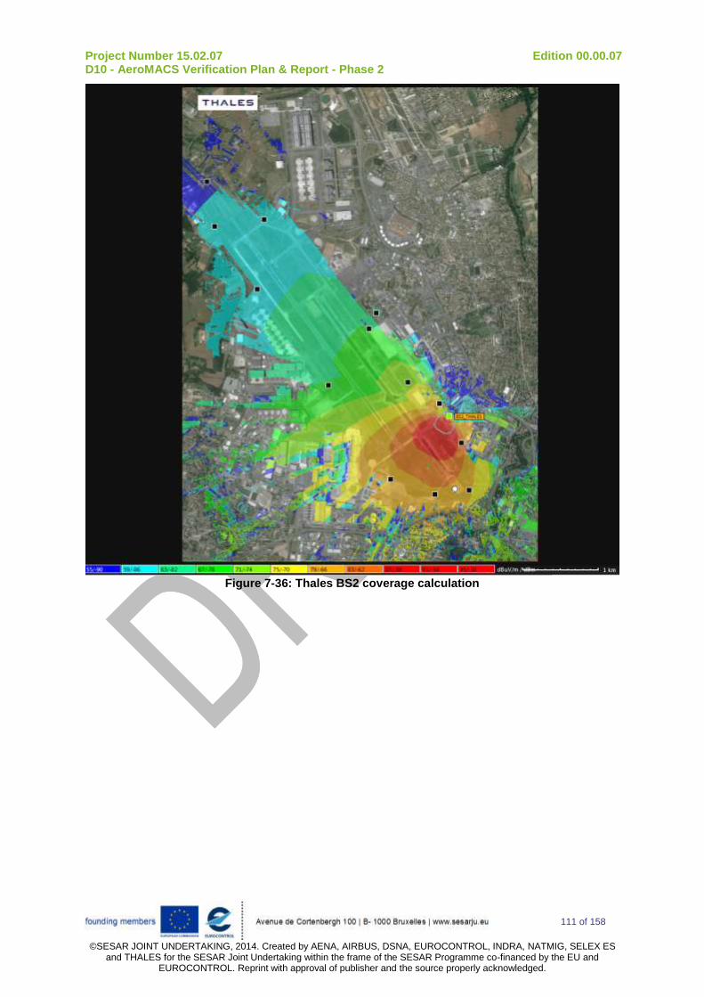
Project Number 15.02.07 Edition 00.00.07 D10 - AeroMACS Verification Plan & Report - Phase 2
111 of 158
©SESAR JOINT UNDERTAKING, 2014. Created by AENA, AIRBUS, DSNA, EUROCONTROL, INDRA, NATMIG, SELEX ES
and THALES for the SESAR Joint Undertaking within the frame of the SESAR Programme co-financed by the EU and EUROCONTROL. Reprint with approval of publisher and the source properly acknowledged.
Figure 7-36: Thales BS2 coverage calculation

Project Number 15.02.07 Edition 00.00.07 D10 - AeroMACS Verification Plan & Report - Phase 2
112 of 158
©SESAR JOINT UNDERTAKING, 2014. Created by AENA, AIRBUS, DSNA, EUROCONTROL, INDRA, NATMIG, SELEX ES
and THALES for the SESAR Joint Undertaking within the frame of the SESAR Programme co-financed by the EU and EUROCONTROL. Reprint with approval of publisher and the source properly acknowledged.
Phase 3 MLS Spectrum measurements The MLS (Microwave Landing Systems) signal use Time Division Multiplexing (TDM) including azimuth and elevation signals. These signals are Continuous Wave (CW) with DPSK preambles with 3 dB bandwidth of 15.626 kHz. It is the preambles that may interfere with other systems and notably AeroMACS due to its low out-of-band attenuation. The frequency of MLS is 5038,8 MHz. In P15.02.07. D04 deliverable, it was stated that “MLS transmitters may cause harmful interference to AeroMACS receivers when installed at the same airport, even when the two systems are separated in frequency by several tens of MHz”. Some measurements were made nearby the MLS (see picture below) in Toulouse to see the impact of MLS on AeroMACS.
Figure 7-37: MLS (south) test location
The frequency gap between Toulouse minimum authorized frequency (5093,5 MHz) and the MLS is: 54,7 MHz. Based on D04, such a frequency gap means that no interferences are expected above a distance of 250 m. More precisely, in D04 assuming a rejection of -70 dB (more than 3 channels spacing from MLS frequency), the interference zone was defined as follow:

Project Number 15.02.07 Edition 00.00.07 D10 - AeroMACS Verification Plan & Report - Phase 2
113 of 158
©SESAR JOINT UNDERTAKING, 2014. Created by AENA, AIRBUS, DSNA, EUROCONTROL, INDRA, NATMIG, SELEX ES
and THALES for the SESAR Joint Undertaking within the frame of the SESAR Programme co-financed by the EU and EUROCONTROL. Reprint with approval of publisher and the source properly acknowledged.
Figure 7-38: MLS (south & north) interference zone with 70dB rejection (source D04)
We went as close as possible from the MLS sites see trajectory below (distance approximately 150 m) to be in the computed interfered area of MLS.
Figure 7-39: MLS tests location
- Close to MLS north (MLS for site angles), we performed in DL a constant 8.9 Mbps
communication (modulation between 64QAM ¾ and 64QAM 5/6) with a DL RSSI of -68 dB: no interferences were apparently noticed.
Pt 9
car

Project Number 15.02.07 Edition 00.00.07 D10 - AeroMACS Verification Plan & Report - Phase 2
114 of 158
©SESAR JOINT UNDERTAKING, 2014. Created by AENA, AIRBUS, DSNA, EUROCONTROL, INDRA, NATMIG, SELEX ES
and THALES for the SESAR Joint Undertaking within the frame of the SESAR Programme co-financed by the EU and EUROCONTROL. Reprint with approval of publisher and the source properly acknowledged.
- In the vicinity of MLS south (MLS for azimuth angles), we performed a DL communication: the DL data rate varied between 3,5 and 5 Mbps (modulation between 16 QAM ½ and 64 QAM 1/2). These variations lead us think about experiencing interferences from the MLS.
- A close up on the recordings near MLS South seems to confirm this assumption: one can see below that the RSSI seems sometimes increased artificially potentially due to MLS interference (left picture), while the CINR is at the same time comparatively low (right picture), confirming the hypothesis of the interferences presence, close to the MLS signal source. A degradation of about 4 dB in CINR (light blue points at center of image) while CINR can increase of about 4 dB (red point at center of image).
Figure 7-40: Close analyse in the vicinity of MLS
Concerning other potential sources of interferences, note that no AMT and no other AeroMACS system signals were detected on the Airport during our field trials. Below the spectrum measurements:
Figure 7-41: Spectrum measurement near MLS signal (south)
MLS
AeroMACS
5150 MHz 5000 MHz

Project Number 15.02.07 Edition 00.00.07 D10 - AeroMACS Verification Plan & Report - Phase 2
115 of 158
©SESAR JOINT UNDERTAKING, 2014. Created by AENA, AIRBUS, DSNA, EUROCONTROL, INDRA, NATMIG, SELEX ES
and THALES for the SESAR Joint Undertaking within the frame of the SESAR Programme co-financed by the EU and EUROCONTROL. Reprint with approval of publisher and the source properly acknowledged.
Figure 7-42: Spectrum measurements near MLS signal (north)
Phase 4 Modulation performances All the modulations were tested in DL and UL from the MS1 on the fix point (PB) and the BS1. Additionally, a test was performed closer from BS1 location with a MS in car to test the upper modulations 64QAM5/6 (see TAIR_20, point 1) as it happens they would not be working at PB. The results are summarized in following table and are similar to what was measured in lab.
Note: the throughput comes from the information displayed by iperf. It is an “UDP” throughput: the
effective radio throughput is a bit higher if one considers the UDP headers.
MCS UL throughput DL throughput
QPSK1/2 0,4 Mbps 1,7 Mbps
QPSK3/4 0,7 Mbps 2,6 Mbps
16QAM1/2 0,9 Mbps 3,5 Mbps
16QAM3/4 1,4 Mbps 5,3 Mbps
64QAM1/2 1,4 Mbps 5,3 Mbps
64QAM2/3 1,9 Mbps 7,0 Mbps
64QAM3/4
KO at fix point (PB) which is too far No other measurement attempt performed 8,0 Mbps
64QAM5/6
KO at PB 2,3 Mbps measured nearer to BS1
KO at PB 8,9 Mbps measured nearer to BS1
Phase 5 QOS performances Each QOS service flow (BE, nRTP, RTP, eRTP, UGS) was successively and dynamically assigned to the MS while having a 1 Mbps communication. The max data rate of each service flow was set to 300 kbps. As expected, the throughput of the communication was limited to 300 kbps once the SF is allocated to the MS.
MLS AeroMACS
5150 MHz 5000 MHz

Project Number 15.02.07 Edition 00.00.07 D10 - AeroMACS Verification Plan & Report - Phase 2
116 of 158
©SESAR JOINT UNDERTAKING, 2014. Created by AENA, AIRBUS, DSNA, EUROCONTROL, INDRA, NATMIG, SELEX ES
and THALES for the SESAR Joint Undertaking within the frame of the SESAR Programme co-financed by the EU and EUROCONTROL. Reprint with approval of publisher and the source properly acknowledged.
Additional results The fix MS at PB is most of the time in line of sight with the BS. In fact, as it is located near the terminal area, it happens that the aircrafts drives close to PB and generates a mask between the MS antenna and the BS antenna (as one can see on the picture below taken from the BS location). The corresponding RSSI degradation was between 10 to 15 dB.
Figure 7-43: Mask due to aircraft which hide the antenna on PB
A measurement of the net entry time was also performed:
- The MS scan is programmed to scan all frequencies between 5093,5 MHz (included) and 5147,5 (included), with a step size of 250 kHz (217 frequencies) (note: all the frequencies are scanned equivalently, no signal threshold etc…)
- The MS is off - The time between the moment when the MS is switched on and a ping is performed
successfully through the AeroMACS link is around: 2 minutes and 10 seconds. All the frequencies were scanned.
A.3.2.3.1 Unexpected behaviors/Results
None
A.3.2.4 Conclusions and recommendations
The TAIR-10 test case allows controlling the installation of the pieces of equipment (BS1 and BS2 in the former control tower, MS in cars and in fix location) and verifying the main performances of AeroMACS on the field.
Additionally, interferences in the vicinity of the MLS were evaluated and the potential effects of Aircraft masks were quantified.
Main conclusion is that the coverage of the whole Toulouse Airport can be achieved with two BS in LOS conditions.

Project Number 15.02.07 Edition 00.00.07 D10 - AeroMACS Verification Plan & Report - Phase 2
117 of 158
©SESAR JOINT UNDERTAKING, 2014. Created by AENA, AIRBUS, DSNA, EUROCONTROL, INDRA, NATMIG, SELEX ES
and THALES for the SESAR Joint Undertaking within the frame of the SESAR Programme co-financed by the EU and EUROCONTROL. Reprint with approval of publisher and the source properly acknowledged.
A.3.3 Verification Exercise # TAIR_020
A.3.3.1 Verification Exercise Scope Cell coverage and MS channel quality reporting: Verify the maximum distance in the airport where the datalink is synchronized, and assess the different modulation schemes and the throughput hence supported. At each point of the “route de service’ in green, stop and perform measurements in LOS (RSSI, max throughput, jitter and delay). The “route de service” is used twice to assess the coverage of the two servicing cells:
first time with BS 1 on (BS 2 off)
and second time with BS2 on (BS 1 off)
A.3.3.2 Conduct of Verification Exercise
A.3.3.2.1 Verification Exercise Preparation
Equipment: BS1&2 + 1 MS in a car+ Spectrum Analyzer Resources:
- Thales: 2 engineers - DSNA: a driver with a car.
Potential measurement points and car trajectories:

Project Number 15.02.07 Edition 00.00.07 D10 - AeroMACS Verification Plan & Report - Phase 2
118 of 158
©SESAR JOINT UNDERTAKING, 2014. Created by AENA, AIRBUS, DSNA, EUROCONTROL, INDRA, NATMIG, SELEX ES
and THALES for the SESAR Joint Undertaking within the frame of the SESAR Programme co-financed by the EU and EUROCONTROL. Reprint with approval of publisher and the source properly acknowledged.

Project Number 15.02.07 Edition 00.00.07 D10 - AeroMACS Verification Plan & Report - Phase 2
119 of 158
©SESAR JOINT UNDERTAKING, 2014. Created by AENA, AIRBUS, DSNA, EUROCONTROL, INDRA, NATMIG, SELEX ES
and THALES for the SESAR Joint Undertaking within the frame of the SESAR Programme co-financed by the EU and EUROCONTROL. Reprint with approval of publisher and the source properly acknowledged.
A.3.3.2.2 Verification Exercise execution
Step action Action result PCO Result
Phase 1 Cell coverage of GS 1
1 GS1 is switched ON
GS2 is switched OFF
GS1 is provisioned with frequency: 5093,5 MHz
Fix MS 1 is OFF
GS 1 is started GS control MMI
OK
2 Set frequency scan of MS 2 (mobile) :
- 5093,5 MHz
- 5098,5 MHz
- 5103,5 MHz
Go to point 1 and stop
MS connects eventually to the GS
F=5093,5 MHz
MS MMI OK
3 Adaptive modulation is selected on the GS as MS profile
Site survey tool is shut down
Perform measurements:
- Write down geo-localization
- Write down measured RSSI / CINR on MS MMI and on BS MMI
- ‘ping’ in both direction and write
Written down are the different measurements
GPS MMI
GS/MS MMI
MS MMI
ping cmd
iperf cmd
OK

Project Number 15.02.07 Edition 00.00.07 D10 - AeroMACS Verification Plan & Report - Phase 2
120 of 158
©SESAR JOINT UNDERTAKING, 2014. Created by AENA, AIRBUS, DSNA, EUROCONTROL, INDRA, NATMIG, SELEX ES
and THALES for the SESAR Joint Undertaking within the frame of the SESAR Programme co-financed by the EU and EUROCONTROL. Reprint with approval of publisher and the source properly acknowledged.
down mean Round Trip Time
- Initiate a bidirectional ‘iperf’ communications to evaluate DL and UL throughput:
o Write down mean maximum throughput
o Write down mean jitter
o Write down the UL and DL modulations (during ‘iperf’)
4 Go to most approrpiate points around airport from 2 to 12 and stop and perform steps 3 to 5 to characterize cell coverage
- - OK
Phase 2 Cell coverage of GS 2
1 GS1 is switched OFF
GS2 is switched ON
GS2 is provisioned with frequency: 5103,5 MHz
Fix MS 1 is OFF
GS 2 is started GS control MMI
OK
2 Set frequency scan of MS 2 (mobile) :
- 5093,5 MHz
- 5098,5 MHz
- 5103,5 MHz
MS connects eventually to the GS
F=5103,5 MHz
MS MMI OK
3 Adaptive modulation is selected on the GS as MS profile
Go to point 1 and stop
Perform measurements:
- Write down geo-localization
- Write down measured RSSI / CINR on MS MMI (site survey tool is shut down) and on BS MMI
- ‘ping’ in both direction and write down mean Round Trip Time (RTT)
- Initiate a bidirectional ‘iperf’ communications to evaluate DL and UL throughput:
o Write down mean maximum throughput
o Write down mean jitter / latency
Written down are the measurements.
GPS MMI
GS/MS MMI
ping cmd
iperf cmd
OK

Project Number 15.02.07 Edition 00.00.07 D10 - AeroMACS Verification Plan & Report - Phase 2
121 of 158
©SESAR JOINT UNDERTAKING, 2014. Created by AENA, AIRBUS, DSNA, EUROCONTROL, INDRA, NATMIG, SELEX ES
and THALES for the SESAR Joint Undertaking within the frame of the SESAR Programme co-financed by the EU and EUROCONTROL. Reprint with approval of publisher and the source properly acknowledged.
o Write down the UL and DL modulations (during ‘iperf’)
6 Go to the most appropriate points 2 to 12 and stop and perform steps 3 to 5 to characterize cell coverage.
- OK
A.3.3.2.3 Deviation from the planned activities
None. TAIR_20 was performed on day 3 as expected.
A.3.3.3 Verification exercise Results
Phase 1 Cell coverage of GS 1
A circle trip was performed all around the airport with stops at some points to perform communications and measurements. It was verified that the modulation and coding scheme were changed accordingly to the received level and signal to noise ratio. The results are also compared with the coverage simulations. The complete set of measurements of BS1 is reported below.
Point 1.1:
- DL RSSI: -47 dBm, UL RSSI: -1101 dBm, UL CINR: 22 dB, DL CINR: 30.5 dB
- Max MCS: 64QAM 5/6 (DL) 64QAM 5/6 (UL)
- Max throughput: 8.91 Mbits/sec (DL), 2.29 Mbits/sec (UL)
- Mean RTT: 72 ms, mean latency: 36 ms, mean jitter: 7 ms
Point 3:
- DL RSSI: -68 dBm, UL RSSI: -117 dBm, UL CINR: 15 dB, DL CINR: 25.5 dB
- Max MCS: 64QAM 5/6 (DL) / 64QAM ½ (UL)
- Max throughput: 8.00 Mbits/sec (DL) / 1.37 Mbits/sec (UL)
- Mean RTT: 70 ms, mean latency: 35 ms , mean jitter: 3 to 8 ms
Point 4:
- DL RSSI: -78 dBm, UL RSSI: -125.0 dBm, UL CINR: 10 dB, DL CINR: 18.3 dB
- Max MCS: 64QAM ½ (DL), QPSK ¾ (UL)
- Max throughput: 4.53 Mbits/sec (DL), 680 Kbits/sec (UL)
- Mean RTT: 78 ms, mean latency: 39 ms , mean jitter: 4 to 7,5 ms
Point 6:
- DL RSSI: -72 dBm, UL RSSI: -121.5 dBm, UL CINR: 11.5 dB, DL CINR: 21.4 dB
- Max MCS: 64QAM 5/6 (DL) 16QAM 1/2 (UL)
- Max throughput: 6.60 Mbits/sec (DL), 743 Kbits/sec (UL)
- Mean RTT: 72 ms, mean latency: 36 ms, mean jitter: 3 to 4 ms
1 In UL the RSSI is measured by subcarrier

Project Number 15.02.07 Edition 00.00.07 D10 - AeroMACS Verification Plan & Report - Phase 2
122 of 158
©SESAR JOINT UNDERTAKING, 2014. Created by AENA, AIRBUS, DSNA, EUROCONTROL, INDRA, NATMIG, SELEX ES
and THALES for the SESAR Joint Undertaking within the frame of the SESAR Programme co-financed by the EU and EUROCONTROL. Reprint with approval of publisher and the source properly acknowledged.
Point 7:
- DL RSSI: -68 dBm, UL RSSI: -114 dBm, UL CINR: 16.5 dB, DL CINR: 23.2 dB
- Max MCS: 64QAM 5/6(DL) / 64QAM ½ (UL)
- Max throughput: 6.79 Mbits/sec (DL) / 1.24 Mbits/sec (UL)
- Mean RTT: 71 ms , mean latency: 36 ms , mean jitter: 3 to 8 ms
Point 9:
- DL RSSI: -70 dBm, UL RSSI: -115,5 dBm, UL CINR: 15 dB, DL CINR: 18.5 / 21.0 dB
- Max MCS: 64QAM ½ (DL) 16QAM ¾ (UL)
- Max throughput: 4.00 Mbits/sec (DL) / 1.25 Mbits/sec (UL)
- Mean RTT: 70 ms, mean latency: 35 ms , mean jitter: 2.5 to 7.5 ms

Project Number 15.02.07 Edition 00.00.07 D10 - AeroMACS Verification Plan & Report - Phase 2
123 of 158
©SESAR JOINT UNDERTAKING, 2014. Created by AENA, AIRBUS, DSNA, EUROCONTROL, INDRA, NATMIG, SELEX ES
and THALES for the SESAR Joint Undertaking within the frame of the SESAR Programme co-financed by the EU and EUROCONTROL. Reprint with approval of publisher and the source properly acknowledged.
Point 11:
- DL RSSI: -87 to -84 dBm, UL RSSI: -126,5 dBm, UL CINR: 0.5, DL CINR: 0 to 2 dB
- Max MCS / Max throughput: no measurements as iperf didn’t work
- Mean RTT: 91 ms (DL: 10% of ping lost, max RTT 341 ms / UL: 28% of ping lost max RTT: 172 ms)
As expected from simulations, this point is at the limit of coverage of BS1.
Point 12:
- DL RSSI: -75 dBm, UL RSSI: -118,5 dBm, UL CINR: 8 dB, DL CINR: 11.0 dB
- Max MCS: 16QAM ½ (DL) / 16QAM ½ (UL)
- Max throughput: 2.27 Mbits/sec (DL) / 745 Kbits/sec (UL)
- Mean RTT: 70 ms, mean latency: 35 ms , mean jitter: 2.7 to 4.8 ms
Contrary to simulations, this point is still reachable from BS1..

Project Number 15.02.07 Edition 00.00.07 D10 - AeroMACS Verification Plan & Report - Phase 2
124 of 158
©SESAR JOINT UNDERTAKING, 2014. Created by AENA, AIRBUS, DSNA, EUROCONTROL, INDRA, NATMIG, SELEX ES
and THALES for the SESAR Joint Undertaking within the frame of the SESAR Programme co-financed by the EU and EUROCONTROL. Reprint with approval of publisher and the source properly acknowledged.
The measurements are compared to the simulations below. Globally the results are similar to simulations. The received level at point 11 and point 12 are much better than expected: it was analysed that it is due to the side lobe of the antenna that was not sufficiently considered in simulation
2. Point 9 is not as good as expected (when compared to point 6 for example). It is believed
that MLS interference could have influenced the data rate at this point.
Figure 7-44: THALES BS1 coverage measurements versus simulation
Phase 2 Cell coverage of GS 2
The complete set of measurements for BS2 is reported below.
Point 1:
- DL RSSI: -70 dBm, UL RSSI: -118.0 dBm, UL CINR: 14.5 dB, DL CINR: 12 dB
- Max MCS: 16QAM ¾ (DL) /16QAM ¾ (UL)
- Max throughput: 3.69 Mbits/sec (DL) / 1.20 Mbits/sec (UL)
- Mean RTT: 72ms, mean latency: 36 ms, mean jitter: 4 to 7,5 ms
2 BS2 coverage simulation was considered with antenna side lobe to confirm this assumption.
-78 dBm / 4.5 Mbps (DL) / 0.68 Mbps (UL)
-68 dBm / 8 Mbps (DL) / 1.37 Mbps (UL)
-72 dBm / 6.6 Mbps (DL) / 0.74 Mbps (UL)
-68 dBm / 6.8 Mbps (DL) / 1.24 Mbps (UL) -47 dBm / 8.9 Mbps (DL) / 2.29 Mbps (UL)
-70 dBm / 4 Mbps (DL) / 1.25 Mbps (UL)
-87 dBm
-75 dBm

Project Number 15.02.07 Edition 00.00.07 D10 - AeroMACS Verification Plan & Report - Phase 2
125 of 158
©SESAR JOINT UNDERTAKING, 2014. Created by AENA, AIRBUS, DSNA, EUROCONTROL, INDRA, NATMIG, SELEX ES
and THALES for the SESAR Joint Undertaking within the frame of the SESAR Programme co-financed by the EU and EUROCONTROL. Reprint with approval of publisher and the source properly acknowledged.
Point B:
- DL RSSI: -79 dBm, UL RSSI: -127.5 dBm, UL CINR: 6 dB, DL CINR: 9,5 dB
- Max MCS: 16QAM ½ (DL) /QPSK ¾ (UL)
- Max throughput: 3.2 Mbits/sec (DL) / 583 Kbits/sec (UL)
- Mean RTT: 73ms, mean latency: 36 ms, mean jitter: 6.5 to 7.5 ms
Point 3:
- DL RSSI: -81 dBm, UL RSSI: -124.5 dBm, UL CINR: 7 dB, DL CINR: 8.79
- Max MCS: QAM16 ½ (DL) / QPSK ½ (UL)
- Max throughput: 3.40 Mbits/sec (DL) / 188 Kbits/sec (UL)
- Mean RTT: 71 ms, mean latency: 35 ms, mean jitter: up to 16 ms (UL)
Point 4:
- DL RSSI: - 86 dBm, UL RSSI: -123.5 dBm, UL CINR: 8 dB, DL CINR: 6.5 dB
- Max MCS: QPSK ½ (DL) / QPSK ½ (UL)
- Max throughput: 2.43 Mbits/sec (DL) / 111 Kbits/sec (UL)
- Mean RTT: 77 ms, Mean latency: 38 ms, mean jitter: 7 up to 22 ms (UL)
Point 5:
- DL RSSI: -83 dBm, UL RSSI: -126 dBm, UL CINR: 7 dB, DL CINR: 9.5 dB
- Max MCS: QAM16 ½ (DL) / QPSK ¾ (UL)
- Max throughput: 3.34 Mbits/sec (DL) / 378 Kbits/sec (UL)
- Mean RTT: 72 ms, mean latency: 36 ms, mean jitter: 5.5 ms
Point 6:
- DL RSSI: -79 dBm, UL RSSI: -125.5 dBm, UL CINR: 7.5 dB, DL CINR: 12.5 dB
- Max MCS: 64QAM ½ (DL) / QPSK ¾ (UL)
- Max throughput: 4.41 Mbits/sec (DL) / 644 Kbits/sec (UL)
- Mean RTT: 63 ms, mean latency: 36 ms, mean jitter: 3.3 to 7.6 ms
Point 7:
- DL RSSI: -67 dBm, UL RSSI: -115.5 dBm, UL CINR: 19.5 dB, DL CINR: 21 dB
- Max MCS: 64QAM 5/6 (DL) / 64QAM 2/3 (UL)
- Max throughput: 8.66 Mbits/sec (DL) / 1.52 Mbits/sec (UL)
- Mean RTT:70 ms , mean latency: 35 ms, mean jitter: 7 to 9 ms
Point 9:
- DL RSSI: -68 dBm, UL RSSI: -114.5 dBm, UL CINR: 20 dB, DL CINR: 21 dB
- Max MCS: 64QAM 5/6 (DL) / 64QAM 2/3 (UL)

Project Number 15.02.07 Edition 00.00.07 D10 - AeroMACS Verification Plan & Report - Phase 2
126 of 158
©SESAR JOINT UNDERTAKING, 2014. Created by AENA, AIRBUS, DSNA, EUROCONTROL, INDRA, NATMIG, SELEX ES
and THALES for the SESAR Joint Undertaking within the frame of the SESAR Programme co-financed by the EU and EUROCONTROL. Reprint with approval of publisher and the source properly acknowledged.
- Max throughput: 8.68 Mbits/sec (DL) / 1,5 Mbits/sec (UL)
- Mean RTT: 70 ms, mean latency: 35 ms, mean jitter: 2.5 ms to 8.5 ms
Point 10:
- DL RSSI: -60 dBm, UL RSSI: -110.0 dBm, UL CINR: 22.5 dB, DL CINR: 22 dB
- Max MCS: 64QAM 5/6 (DL) / 64QAM 5/6 (UL)
- Max throughput: 8.90 Mbits/sec / 1.59 Mbits/sec
- Mean RTT: 69 ms, mean latency: 35 ms, mean jitter: 2.5 ms to 8.5 ms
Point 11:
- DL RSSI: -65, UL RSSI: -110.0, UL CINR: 23.0, DL CINR: 21
- Max MCS: 64QAM 5/6 (DL) / 64QAM 5/6 (UL)
- Max throughput: 7.94 Mbits/sec (DL) / 1.46 Mbits/sec (UL)
- Mean RTT: 70 ms, mean latency: 35 ms, mean jitter: 3 to 6.5 ms
Point 12:
- DL RSSI: -59 dBm, UL RSSI: -108.5 dBm, UL CINR: 21.5 dB, DL CINR: 16.5 dB
- Max MCS: 64QAM ¾ (DL) / 64QAM 5/6 (UL)
- Max throughput: 7.34 Mbits/sec / 1.97 Mbits/sec
- Mean RTT: 77 ms, mean latency: 38 ms, mean jitter: 3 to 6,5 ms

Project Number 15.02.07 Edition 00.00.07 D10 - AeroMACS Verification Plan & Report - Phase 2
127 of 158
©SESAR JOINT UNDERTAKING, 2014. Created by AENA, AIRBUS, DSNA, EUROCONTROL, INDRA, NATMIG, SELEX ES
and THALES for the SESAR Joint Undertaking within the frame of the SESAR Programme co-financed by the EU and EUROCONTROL. Reprint with approval of publisher and the source properly acknowledged.
The measurements are compared to the simulations below. Globally the results are similar to simulations.
Figure 7-45: BS2 coverage measurements versus coverage simulation
Additional measurements
A measurement was done in extremely low reception conditions in the DGAC parking. With a RSSI around -91 dBm, a DL communications was established in QPSK ½ still offering 1 Mbps DL (TDD ratio 32/15).
A.3.3.3.1 Unexpected behaviors/Results
None
A.3.3.4 Conclusions and recommendations
The test allowed making cell coverage for BS1 on one side and BS2 on the other side. Good performances were reported. They are generally in accordance with simulations.
-70 dBm / 3.7 Mbps (DL) / 1.2 Mbps (UL)
-79 dBm / 3.2 Mbps (DL) / 0.6 Mbps (UL)
-81 dBm / 3.4 Mbps (DL) / 0.2 Mbps (UL)
-86 dBm / 2.4 Mbps (DL) / 0.1 Mbps (UL)
-83 dBm / 3.3 Mbps (DL) / 0.3 Mbps (UL)
-79 dBm / 4.4 Mbps (DL) / 0.6 Mbps (UL)
-68 dBm / 8.6 Mbps (DL) / 1.5 Mbps (UL)
-68 dBm / 8.6 Mbps (DL) / 1.5 Mbps (UL) -65 dBm / 7.9 Mbps (DL) / 1.5 Mbps (UL)
-59 dBm / 7.3 Mbps (DL) / 1.9 Mbps (UL)
192.168.0.67

Project Number 15.02.07 Edition 00.00.07 D10 - AeroMACS Verification Plan & Report - Phase 2
128 of 158
©SESAR JOINT UNDERTAKING, 2014. Created by AENA, AIRBUS, DSNA, EUROCONTROL, INDRA, NATMIG, SELEX ES
and THALES for the SESAR Joint Undertaking within the frame of the SESAR Programme co-financed by the EU and EUROCONTROL. Reprint with approval of publisher and the source properly acknowledged.
A.3.4 Verification Exercise # TAIR_030
A.3.4.1 Verification Exercise Scope Real deployment and NLOS performances: Evaluate the impact of buildings, hangars on the strength of the signal. Stop in places with near-LOS or Non-LOS conditions. As far as possible, different kind of zones of the Airport are visited: ramp Area, parking Area, Tower Area, Access roads to installations for maintenance operations.
A.3.4.2 Conduct of Verification Exercise
A.3.4.2.1 Verification Exercise Preparation
Equipment: BS1&2 + 1 MS in a car+ Spectrum Analyzer Resources:
- Thales: 2 engineers - DSNA: a driver with a car.
Measurement points and car trajectories:

Project Number 15.02.07 Edition 00.00.07 D10 - AeroMACS Verification Plan & Report - Phase 2
129 of 158
©SESAR JOINT UNDERTAKING, 2014. Created by AENA, AIRBUS, DSNA, EUROCONTROL, INDRA, NATMIG, SELEX ES
and THALES for the SESAR Joint Undertaking within the frame of the SESAR Programme co-financed by the EU and EUROCONTROL. Reprint with approval of publisher and the source properly acknowledged.

Project Number 15.02.07 Edition 00.00.07 D10 - AeroMACS Verification Plan & Report - Phase 2
130 of 158
©SESAR JOINT UNDERTAKING, 2014. Created by AENA, AIRBUS, DSNA, EUROCONTROL, INDRA, NATMIG, SELEX ES
and THALES for the SESAR Joint Undertaking within the frame of the SESAR Programme co-financed by the EU and EUROCONTROL. Reprint with approval of publisher and the source properly acknowledged.

Project Number 15.02.07 Edition 00.00.07 D10 - AeroMACS Verification Plan & Report - Phase 2
131 of 158
©SESAR JOINT UNDERTAKING, 2014. Created by AENA, AIRBUS, DSNA, EUROCONTROL, INDRA, NATMIG, SELEX ES
and THALES for the SESAR Joint Undertaking within the frame of the SESAR Programme co-financed by the EU and EUROCONTROL. Reprint with approval of publisher and the source properly acknowledged.

Project Number 15.02.07 Edition 00.00.07 D10 - AeroMACS Verification Plan & Report - Phase 2
132 of 158
©SESAR JOINT UNDERTAKING, 2014. Created by AENA, AIRBUS, DSNA, EUROCONTROL, INDRA, NATMIG, SELEX ES
and THALES for the SESAR Joint Undertaking within the frame of the SESAR Programme co-financed by the EU and EUROCONTROL. Reprint with approval of publisher and the source properly acknowledged.
A.3.4.2.2 Verification Exercise execution
Step action Action result PCO Result
1 GS1 is switched ON
GS2 is switched OFF
GS1 is provisioned with frequency: 5093,5 MHz
Fix MS is OFF
Adaptive modulation is selected on the GS as MS profile
GS 1 is started GS control MMI
OK
2 Set frequency scan of mobile MS:
- 5093,5 MHz
- 5098,5 MHz
- 5103,5 MHz
MS connects eventually to the GS
F=5093,5 MHz
MS MMI OK
3 Perform a trip on the “NLOS car trajectory” (green below) and record MS RSSI on the fly with survey tool
RSSI recorded on the map Survey tool OK
4 Go to point 1 and stop
- - -
5 Adaptive modulation is selected on the GS as MS profile
Perform measurements:
- Write down geo-localization / (Take a picture to illustrate the NLOS conditions)
- Write down measured RSSI / CINR on MS MMI (site survey tool is shut down) and on BS MMI
- ‘ping’ in both direction and write down mean Round Trip Time
- Initiate a bidirectional ‘iperf’ communications to evaluate DL and UL throughput:
o Write down mean maximum throughput
o Write down mean jitter
o Write down the UL and DL modulations (during ‘iperf’)
Written down are the measurements
GS/MS MMI
ping cmd
iperf cmd
GPS MMI
OK
8 Go to ‘NLOS’ measurement point 3, 5, 7, 9, 11, 13, 15, 18, 19 and stop where possible and perform steps 5 to 7
- OK

Project Number 15.02.07 Edition 00.00.07 D10 - AeroMACS Verification Plan & Report - Phase 2
133 of 158
©SESAR JOINT UNDERTAKING, 2014. Created by AENA, AIRBUS, DSNA, EUROCONTROL, INDRA, NATMIG, SELEX ES
and THALES for the SESAR Joint Undertaking within the frame of the SESAR Programme co-financed by the EU and EUROCONTROL. Reprint with approval of publisher and the source properly acknowledged.
A.3.4.2.3 Deviation from the planned activities
None.
A.3.4.3 Verification exercise Results
The recordings of the DL RSSI on the fly are in accordance with the NLOS conditions: the more obstacles, the less signal. Communications are still possible even in very important NON LOS conditions. The distances are between 330 m (point #1) and 1400 m (point #19). Detailed performances and pictures of the “NLOS” position are displayed in following pages.
Figure 7-46: Recordings on the Fly of the RSSI in NLOS conditions

Project Number 15.02.07 Edition 00.00.07 D10 - AeroMACS Verification Plan & Report - Phase 2
134 of 158
©SESAR JOINT UNDERTAKING, 2014. Created by AENA, AIRBUS, DSNA, EUROCONTROL, INDRA, NATMIG, SELEX ES and THALES for the SESAR Joint Undertaking within the frame of
the SESAR Programme co-financed by the EU and EUROCONTROL. Reprint with approval of publisher and the source properly acknowledged.
Figure 7-47: NLOS point #1 measurement details

Project Number 15.02.07 Edition 00.00.07 D10 - AeroMACS Verification Plan & Report - Phase 2
135 of 158
©SESAR JOINT UNDERTAKING, 2014. Created by AENA, AIRBUS, DSNA, EUROCONTROL, INDRA, NATMIG, SELEX ES and THALES for the SESAR Joint Undertaking within the frame of
the SESAR Programme co-financed by the EU and EUROCONTROL. Reprint with approval of publisher and the source properly acknowledged.
Figure 7-48: NLOS point #3 measurement details

Project Number 15.02.07 Edition 00.00.07 D10 - AeroMACS Verification Plan & Report - Phase 2
136 of 158
©SESAR JOINT UNDERTAKING, 2014. Created by AENA, AIRBUS, DSNA, EUROCONTROL, INDRA, NATMIG, SELEX ES and THALES for the SESAR Joint Undertaking within the frame of
the SESAR Programme co-financed by the EU and EUROCONTROL. Reprint with approval of publisher and the source properly acknowledged.
Figure 7-49: NLOS point #7 measurement details
Note: This point was quite in visibility with the BS although it was located at the ramp access.

Project Number 15.02.07 Edition 00.00.07 D10 - AeroMACS Verification Plan & Report - Phase 2
137 of 158
©SESAR JOINT UNDERTAKING, 2014. Created by AENA, AIRBUS, DSNA, EUROCONTROL, INDRA, NATMIG, SELEX ES and THALES for the SESAR Joint Undertaking within the frame of
the SESAR Programme co-financed by the EU and EUROCONTROL. Reprint with approval of publisher and the source properly acknowledged.
Figure 7-50: NLOS point #9 measurement details

Project Number 15.02.07 Edition 00.00.07 D10 - AeroMACS Verification Plan & Report - Phase 2
138 of 158
©SESAR JOINT UNDERTAKING, 2014. Created by AENA, AIRBUS, DSNA, EUROCONTROL, INDRA, NATMIG, SELEX ES and THALES for the SESAR Joint Undertaking within the frame of
the SESAR Programme co-financed by the EU and EUROCONTROL. Reprint with approval of publisher and the source properly acknowledged.
Figure 7-51: NLOS point #11 measurement details

Project Number 15.02.07 Edition 00.00.07 D10 - AeroMACS Verification Plan & Report - Phase 2
139 of 158
©SESAR JOINT UNDERTAKING, 2014. Created by AENA, AIRBUS, DSNA, EUROCONTROL, INDRA, NATMIG, SELEX ES and THALES for the SESAR Joint Undertaking within the frame of
the SESAR Programme co-financed by the EU and EUROCONTROL. Reprint with approval of publisher and the source properly acknowledged.
Figure 7-52: NLOS point #13 measurement details

Project Number 15.02.07 Edition 00.00.07 D10 - AeroMACS Verification Plan & Report - Phase 2
140 of 158
©SESAR JOINT UNDERTAKING, 2014. Created by AENA, AIRBUS, DSNA, EUROCONTROL, INDRA, NATMIG, SELEX ES and THALES for the SESAR Joint Undertaking within the frame of
the SESAR Programme co-financed by the EU and EUROCONTROL. Reprint with approval of publisher and the source properly acknowledged.
Figure 7-53: NLOS point #15 measurement details

Project Number 15.02.07 Edition 00.00.07 D10 - AeroMACS Verification Plan & Report - Phase 2
141 of 158
©SESAR JOINT UNDERTAKING, 2014. Created by AENA, AIRBUS, DSNA, EUROCONTROL, INDRA, NATMIG, SELEX ES and THALES for the SESAR Joint Undertaking within the frame of
the SESAR Programme co-financed by the EU and EUROCONTROL. Reprint with approval of publisher and the source properly acknowledged.
Figure 7-54: NLOS point #18 measurement details

Project Number 15.02.07 Edition 00.00.07 D10 - AeroMACS Verification Plan & Report - Phase 2
142 of 158
©SESAR JOINT UNDERTAKING, 2014. Created by AENA, AIRBUS, DSNA, EUROCONTROL, INDRA, NATMIG, SELEX ES and THALES for the SESAR Joint Undertaking within the frame of
the SESAR Programme co-financed by the EU and EUROCONTROL. Reprint with approval of publisher and the source properly acknowledged.
Figure 7-55: NLOS point #19 measurement details
7.5

Project Number 15.02.07 Edition 00.00.07 D10 - AeroMACS Verification Plan & Report - Phase 2
143 of 158
©SESAR JOINT UNDERTAKING, 2014. Created by AENA, AIRBUS, DSNA, EUROCONTROL, INDRA, NATMIG, SELEX ES
and THALES for the SESAR Joint Undertaking within the frame of the SESAR Programme co-financed by the EU and EUROCONTROL. Reprint with approval of publisher and the source properly acknowledged.
Additional measurements
We had an opportunity to do some measurements outside of the Airport; these measurements are reported below.
Figure 7-56: Measurements on the outside of the Airport
A.3.4.3.1 Unexpected behaviors/Results
None
A.3.4.4 Conclusions and recommendations
The testing allowed showing the impact of NLOS conditions of propagation.
Up to 10-20 dB of attenuation can be noticed in the worst case (NLOS point 19 compared to LOS PB point (fix MS)). Still the communications are still possible with off course limited data rates compared with LOS conditions (fix MS in PB compared to NLOS point 19 for example).
Simulations were also performed but they are too much pessimistic compared to field results. As an example the figure below shows that no communications are expected in the gates area. One should

Project Number 15.02.07 Edition 00.00.07 D10 - AeroMACS Verification Plan & Report - Phase 2
144 of 158
©SESAR JOINT UNDERTAKING, 2014. Created by AENA, AIRBUS, DSNA, EUROCONTROL, INDRA, NATMIG, SELEX ES
and THALES for the SESAR Joint Undertaking within the frame of the SESAR Programme co-financed by the EU and EUROCONTROL. Reprint with approval of publisher and the source properly acknowledged.
note that even if we use a clutter map to represent the obstacles above the ground this represents not all the real phenomena explaining the differences between simulations and field measurements.
Figure 7-57: Simulated field strength near the terminal
In general, we found in the NLOS conditions:
- Mean UL modulation: QPSK ¾, Mean DL modulation : 16QAM ½
- UL Throughput from 200 kbits/s up to 750 kbits/s in the most adverse situations in the Toulouse configuration (point #9 up to # 19) and from 1 to 1.5 Mbit/s in nearer NLOS location from BS (point #3 and point #1). 2.26 Mbits/s in point #7 which was more in LOS.
- DL Throughput from 2.3 Mbits/s up to 4.2 Mbits/s in the most adverse situations in the Toulouse configuration (point #9 up to # 19) and up to 8.9 Mbits/s in the nearest NLOS location (point #1).
In the case of AeroMACS on board an aircraft, we can expect far better propagation conditions as the antenna will be at the top of the Aircraft (several meters above the ground) and the Aircraft in front of the terminals. In this case, it is expected to be very often in the best case situation represented by point #7.
Finally, we were able to perform a relatively good (video tuned to a 500 kbps constant bit rate) quality video communications between the MS and the BS to confirm this good behaviour.
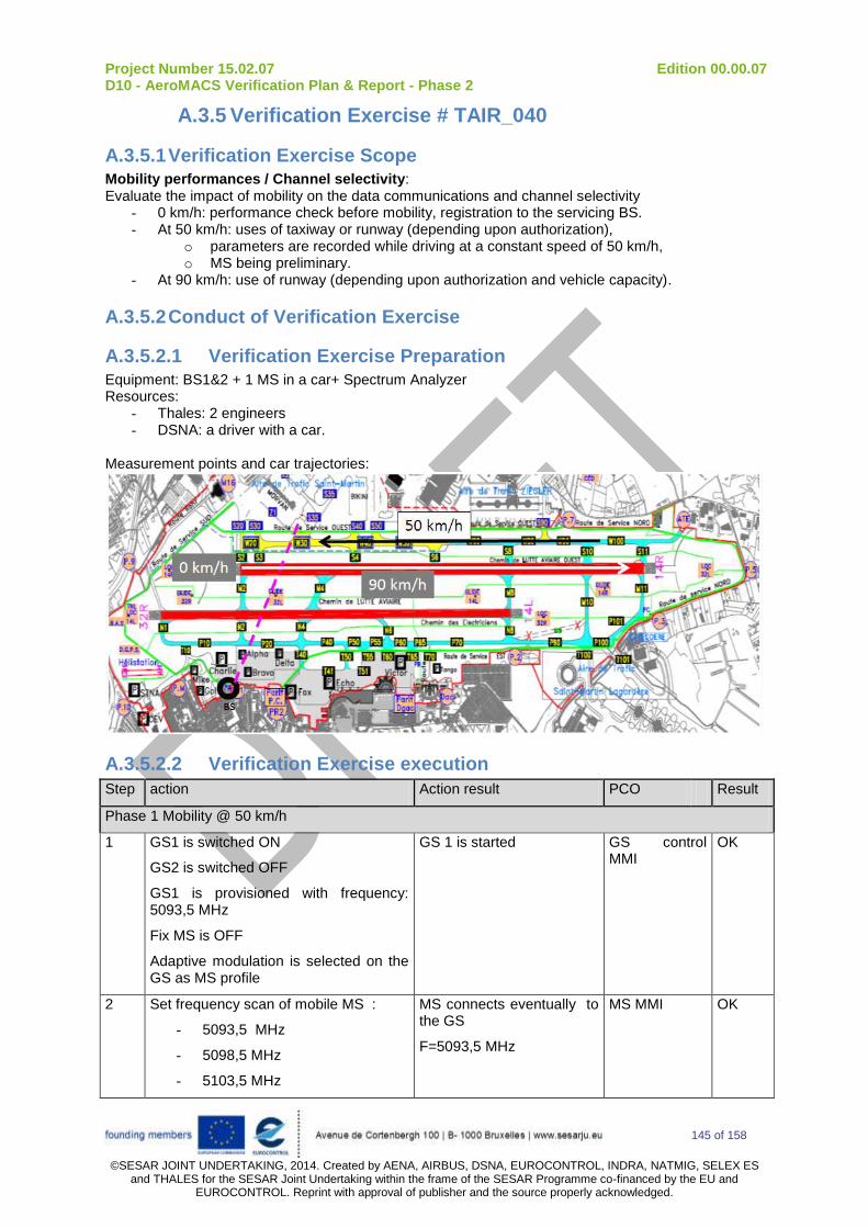
Project Number 15.02.07 Edition 00.00.07 D10 - AeroMACS Verification Plan & Report - Phase 2
145 of 158
©SESAR JOINT UNDERTAKING, 2014. Created by AENA, AIRBUS, DSNA, EUROCONTROL, INDRA, NATMIG, SELEX ES
and THALES for the SESAR Joint Undertaking within the frame of the SESAR Programme co-financed by the EU and EUROCONTROL. Reprint with approval of publisher and the source properly acknowledged.
A.3.5 Verification Exercise # TAIR_040
A.3.5.1 Verification Exercise Scope Mobility performances / Channel selectivity: Evaluate the impact of mobility on the data communications and channel selectivity
- 0 km/h: performance check before mobility, registration to the servicing BS. - At 50 km/h: uses of taxiway or runway (depending upon authorization),
o parameters are recorded while driving at a constant speed of 50 km/h, o MS being preliminary.
- At 90 km/h: use of runway (depending upon authorization and vehicle capacity).
A.3.5.2 Conduct of Verification Exercise
A.3.5.2.1 Verification Exercise Preparation
Equipment: BS1&2 + 1 MS in a car+ Spectrum Analyzer Resources:
- Thales: 2 engineers - DSNA: a driver with a car.
Measurement points and car trajectories:
A.3.5.2.2 Verification Exercise execution
Step action Action result PCO Result
Phase 1 Mobility @ 50 km/h
1 GS1 is switched ON
GS2 is switched OFF
GS1 is provisioned with frequency: 5093,5 MHz
Fix MS is OFF
Adaptive modulation is selected on the GS as MS profile
GS 1 is started GS control MMI
OK
2 Set frequency scan of mobile MS :
- 5093,5 MHz
- 5098,5 MHz
- 5103,5 MHz
MS connects eventually to the GS
F=5093,5 MHz
MS MMI OK

Project Number 15.02.07 Edition 00.00.07 D10 - AeroMACS Verification Plan & Report - Phase 2
146 of 158
©SESAR JOINT UNDERTAKING, 2014. Created by AENA, AIRBUS, DSNA, EUROCONTROL, INDRA, NATMIG, SELEX ES
and THALES for the SESAR Joint Undertaking within the frame of the SESAR Programme co-financed by the EU and EUROCONTROL. Reprint with approval of publisher and the source properly acknowledged.
3 Vehicle is stopped at the start of the runway or taxiway. Start survey tool.
Perform a trip @ 50 km/h on the car trajectory (runway or taxiway) and record MS RSSI on the fly with survey tool.
RSSI recorded on the map
Survey tool
OK
4 Vehicle is stopped at the start of the runway or taxiway. Survey tool is shut down.
Start “iperf” with a duration greater than trip duration in both direction
Perform a second trip @ 50 km/h on the car trajectory (runway or taxiway).
Stop iperf and write down iperf results
Results recorded Iperf cmd
OK
5 Perform step 3 & 4 at 90 km/h Results recorded OK
120 km/h also done

Project Number 15.02.07 Edition 00.00.07 D10 - AeroMACS Verification Plan & Report - Phase 2
147 of 158
©SESAR JOINT UNDERTAKING, 2014. Created by AENA, AIRBUS, DSNA, EUROCONTROL, INDRA, NATMIG, SELEX ES
and THALES for the SESAR Joint Undertaking within the frame of the SESAR Programme co-financed by the EU and EUROCONTROL. Reprint with approval of publisher and the source properly acknowledged.
A.3.5.2.3 Deviation from the planned activities
The mobility tests were done on the day planned. The speed tests were done on the taxiway at 50 km/h, 90 km/h and also up to 120 km/h. Finally the mobility test was located on the Whisky Taxiway from W60 to W100 which was more convenient regarding aircraft traffic and was also interesting in terms of distance from the BS (the farthest possible location). Off course, we gave priority to the Aircrafts, as shown below.
Figure 7-58: Mobility test location (ATE -> Taxiway W 100 to W 60 – round trip)
Figure 7-59: Priority to the Aircrafts traffic on the taxiway

Project Number 15.02.07 Edition 00.00.07 D10 - AeroMACS Verification Plan & Report - Phase 2
148 of 158
©SESAR JOINT UNDERTAKING, 2014. Created by AENA, AIRBUS, DSNA, EUROCONTROL, INDRA, NATMIG, SELEX ES
and THALES for the SESAR Joint Undertaking within the frame of the SESAR Programme co-financed by the EU and EUROCONTROL. Reprint with approval of publisher and the source properly acknowledged.
A.3.5.3 Verification exercise Results
Below, the maps show the recordings of the DL RSSI at the different speed: 50 km/h, 90 km/h and 120 km/h. The mean achieved data rates are also mentioned.
Figure 7-60: recorded RSSI of mobility test at 50 km/h
The mean data throughputs obtained during the round trip at 50 km/h are:
- 7,4 Mbits/sec in DL
- 1 Mbits/sec in UL
We did also a round trip with fix data rates lower than the maximum achievable ones:
- In UL 400 Kbits/sec was generated and transmitted with no errors
- In DL 1.50 Mbits/sec was generated and transmitted with no errors

Project Number 15.02.07 Edition 00.00.07 D10 - AeroMACS Verification Plan & Report - Phase 2
149 of 158
©SESAR JOINT UNDERTAKING, 2014. Created by AENA, AIRBUS, DSNA, EUROCONTROL, INDRA, NATMIG, SELEX ES
and THALES for the SESAR Joint Undertaking within the frame of the SESAR Programme co-financed by the EU and EUROCONTROL. Reprint with approval of publisher and the source properly acknowledged.
Figure 7-61: recorded RSSI of mobility test at 90 km/h
The mean data throughputs obtained during the round trip at 90 km/h are:
- 6,98 Mbits/sec in DL,
- 918 kbits/sec in UL.
We did also a round trip with fix data rates lower than the maximum achievable ones:
- In UL a data stream of 400 Kbits/sec was generated and transmitted with no errors,
- In DL a data stream of 1.50 Mbits/sec was generated and transmitted with no errors.
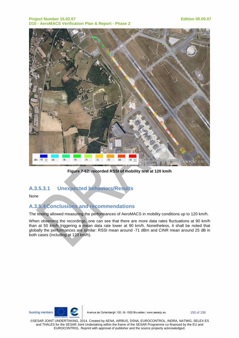
Project Number 15.02.07 Edition 00.00.07 D10 - AeroMACS Verification Plan & Report - Phase 2
150 of 158
©SESAR JOINT UNDERTAKING, 2014. Created by AENA, AIRBUS, DSNA, EUROCONTROL, INDRA, NATMIG, SELEX ES
and THALES for the SESAR Joint Undertaking within the frame of the SESAR Programme co-financed by the EU and EUROCONTROL. Reprint with approval of publisher and the source properly acknowledged.
Figure 7-62: recorded RSSI of mobility test at 120 km/h
A.3.5.3.1 Unexpected behaviors/Results
None
A.3.5.4 Conclusions and recommendations
The testing allowed measuring the performances of AeroMACS in mobility conditions up to 120 km/h.
When observing the recordings, one can see that there are more data rates fluctuations at 90 km/h than at 50 km/h triggering a mean data rate lower at 90 km/h. Nonetheless, it shall be noted that globally the performances are similar: RSSI mean around -71 dBm and CINR mean around 25 dB in both cases (including at 120 km/h).

Project Number 15.02.07 Edition 00.00.07 D10 - AeroMACS Verification Plan & Report - Phase 2
151 of 158
©SESAR JOINT UNDERTAKING, 2014. Created by AENA, AIRBUS, DSNA, EUROCONTROL, INDRA, NATMIG, SELEX ES
and THALES for the SESAR Joint Undertaking within the frame of the SESAR Programme co-financed by the EU and EUROCONTROL. Reprint with approval of publisher and the source properly acknowledged.
A.3.6 Verification Exercise # TAIR_050
A.3.6.1 Verification Exercise Scope Multi-channel test: Evaluate the impact of 2 BS with overlapping coverage using alternate or adjacent channels
- BS1 and BS2 are on, - 3 MS used: 2 vehicles and 1 fix point.
A.3.6.2 Conduct of Verification Exercise
A.3.6.2.1 Verification Exercise Preparation Equipment: BS1&2 + 2 MS in a car + 1 fix MS Resources: - Thales: 3 engineers - DSNA: 2 drivers / 2 cars. In order to define the car trajectories, the best server map was calculated:
Figure 7-63: THALES BS1 / BS2 best server map

Project Number 15.02.07 Edition 00.00.07 D10 - AeroMACS Verification Plan & Report - Phase 2
152 of 158
©SESAR JOINT UNDERTAKING, 2014. Created by AENA, AIRBUS, DSNA, EUROCONTROL, INDRA, NATMIG, SELEX ES
and THALES for the SESAR Joint Undertaking within the frame of the SESAR Programme co-financed by the EU and EUROCONTROL. Reprint with approval of publisher and the source properly acknowledged.
Measurement points and car trajectories:
A.3.6.2.2 Verification Exercise execution
Step action Action result PCO Result
Phase 1 Multi-channel tests with alternate channels spacing
1 GS1 is switched ON
F=5093,5 MHz
GS2 is switched ON
F=5103,5 MHz
Adaptive modulation is selected on the GS as MS profile
GS 1 is started
GS 2 is started
GS control MMI
OK
2 Go to fix MS location
Set frequency on fix MS to 5093,5 MHz
Write down RSSI
Fix MS connects eventually to the GS 1
F=5093,5 MHz
(screenshot of MS MMI)
MS MMI OK
3 Set frequency on the two mobile MS:
MS in car 1
- 5093,5 MHz
MS in car 2
- 5103,5 MHz
Go to point 1 with cars
Write down RSSI
MS in car 1 connects eventually to the GS 1
F=5093,5 MHz
MS in car 2 connects eventually to the GS 2
F=5103,5 MHz
RSSI written down for both MS
(screenshot of MS MMI)
MS MMI OK
4 Start survey tool.
GO with both cars from point 1 to point 7 with no stop (the cars are going through the overlapping area)
RSSI recorded on the map Survey tool OK
BS
235
6
4
fix MS
BS2
BS1 1
7
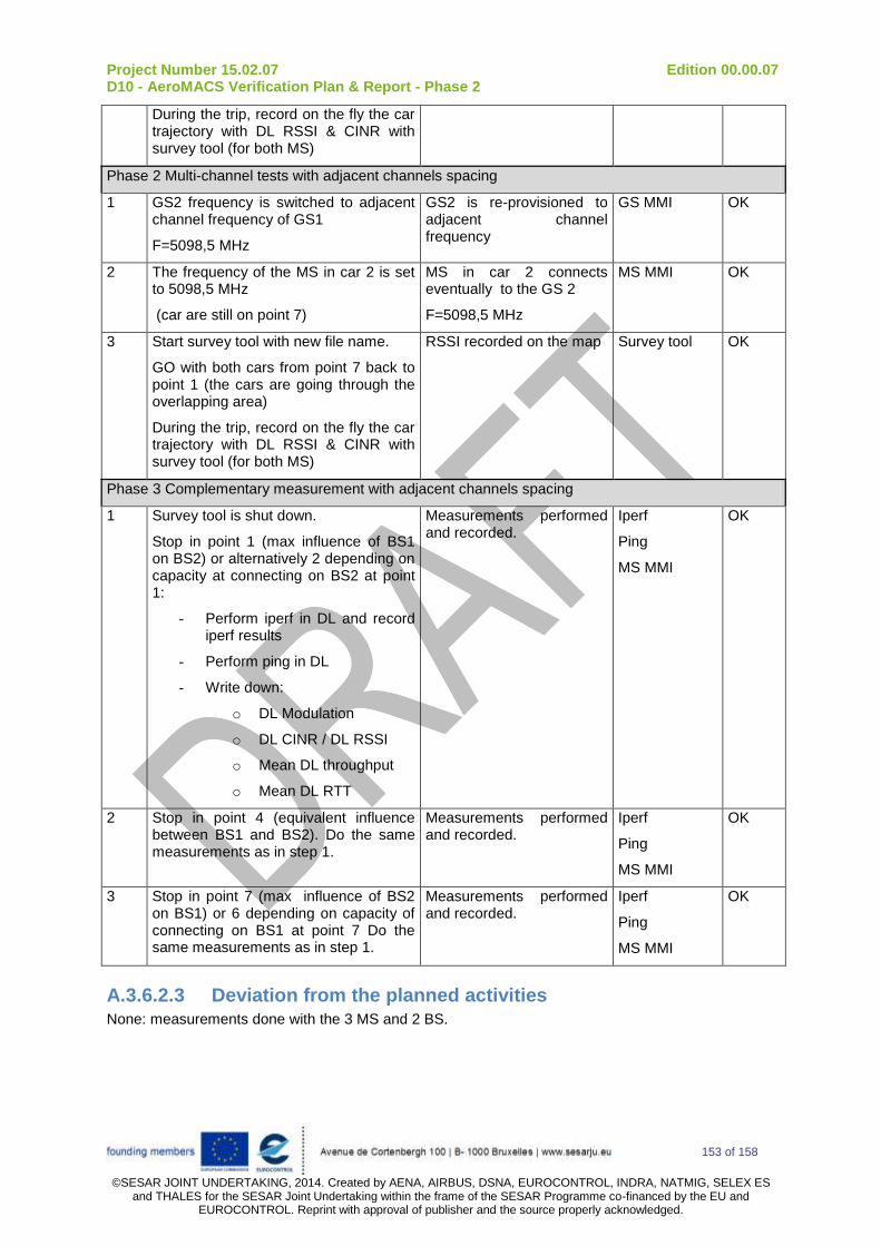
Project Number 15.02.07 Edition 00.00.07 D10 - AeroMACS Verification Plan & Report - Phase 2
153 of 158
©SESAR JOINT UNDERTAKING, 2014. Created by AENA, AIRBUS, DSNA, EUROCONTROL, INDRA, NATMIG, SELEX ES
and THALES for the SESAR Joint Undertaking within the frame of the SESAR Programme co-financed by the EU and EUROCONTROL. Reprint with approval of publisher and the source properly acknowledged.
During the trip, record on the fly the car trajectory with DL RSSI & CINR with survey tool (for both MS)
Phase 2 Multi-channel tests with adjacent channels spacing
1 GS2 frequency is switched to adjacent channel frequency of GS1
F=5098,5 MHz
GS2 is re-provisioned to adjacent channel frequency
GS MMI OK
2 The frequency of the MS in car 2 is set to 5098,5 MHz
(car are still on point 7)
MS in car 2 connects eventually to the GS 2
F=5098,5 MHz
MS MMI OK
3 Start survey tool with new file name.
GO with both cars from point 7 back to point 1 (the cars are going through the overlapping area)
During the trip, record on the fly the car trajectory with DL RSSI & CINR with survey tool (for both MS)
RSSI recorded on the map Survey tool OK
Phase 3 Complementary measurement with adjacent channels spacing
1 Survey tool is shut down.
Stop in point 1 (max influence of BS1 on BS2) or alternatively 2 depending on capacity at connecting on BS2 at point 1:
- Perform iperf in DL and record iperf results
- Perform ping in DL
- Write down:
o DL Modulation
o DL CINR / DL RSSI
o Mean DL throughput
o Mean DL RTT
Measurements performed and recorded.
Iperf
Ping
MS MMI
OK
2 Stop in point 4 (equivalent influence between BS1 and BS2). Do the same measurements as in step 1.
Measurements performed and recorded.
Iperf
Ping
MS MMI
OK
3 Stop in point 7 (max influence of BS2 on BS1) or 6 depending on capacity of connecting on BS1 at point 7 Do the same measurements as in step 1.
Measurements performed and recorded.
Iperf
Ping
MS MMI
OK
A.3.6.2.3 Deviation from the planned activities None: measurements done with the 3 MS and 2 BS.

Project Number 15.02.07 Edition 00.00.07 D10 - AeroMACS Verification Plan & Report - Phase 2
154 of 158
©SESAR JOINT UNDERTAKING, 2014. Created by AENA, AIRBUS, DSNA, EUROCONTROL, INDRA, NATMIG, SELEX ES
and THALES for the SESAR Joint Undertaking within the frame of the SESAR Programme co-financed by the EU and EUROCONTROL. Reprint with approval of publisher and the source properly acknowledged.
Figure 7-64: The two MS at point 7
Figure 7-65: 3 MS at PB

Project Number 15.02.07 Edition 00.00.07 D10 - AeroMACS Verification Plan & Report - Phase 2
155 of 158
©SESAR JOINT UNDERTAKING, 2014. Created by AENA, AIRBUS, DSNA, EUROCONTROL, INDRA, NATMIG, SELEX ES
and THALES for the SESAR Joint Undertaking within the frame of the SESAR Programme co-financed by the EU and EUROCONTROL. Reprint with approval of publisher and the source properly acknowledged.
A.3.6.3 Verification exercise Results
Figure 7-66: Alternate channels - BS1 measurements
Figure 7-67: Adjacent channels - BS1 measurements

Project Number 15.02.07 Edition 00.00.07 D10 - AeroMACS Verification Plan & Report - Phase 2
156 of 158
©SESAR JOINT UNDERTAKING, 2014. Created by AENA, AIRBUS, DSNA, EUROCONTROL, INDRA, NATMIG, SELEX ES
and THALES for the SESAR Joint Undertaking within the frame of the SESAR Programme co-financed by the EU and EUROCONTROL. Reprint with approval of publisher and the source properly acknowledged.
Figure 7-68: Alternate channels - BS2 measurements
Figure 7-69: Adjacent channels - BS2 measurements

Project Number 15.02.07 Edition 00.00.07 D10 - AeroMACS Verification Plan & Report - Phase 2
157 of 158
©SESAR JOINT UNDERTAKING, 2014. Created by AENA, AIRBUS, DSNA, EUROCONTROL, INDRA, NATMIG, SELEX ES
and THALES for the SESAR Joint Undertaking within the frame of the SESAR Programme co-financed by the EU and EUROCONTROL. Reprint with approval of publisher and the source properly acknowledged.
From previous recordings, one can see that operating on adjacent or alternate channels seems not to have a noticeable difference.
For instance measures of RSSI and CINR at point 1 for BS2, using alternate (5103,5 MHz) or adjacent channel (5098,5 MHz) to BS1 (5093,5 MHz, DL RSSI = -74 dBm) are similar: around -83 dBm and 10 dB. Besides, the communication is established with: DL throughput of 3,10 Mbps and UL throughput 470 kbps similar to what was obtained in TAIR_20_point#5, where BS1 was off.
The same applies for BS1 at point 7: RSSI = -85 dBm and CINR = 4 dB in both cases, BS2 being on alternate channels or BS2 being on adjacent channels (with a DL RSSI level of -66 dBm).
Additional results:
Test with 3 MS (DL RSSI fix MS ~ -62 dBm and DL RSSI Mobile MS ~ -70 dBm) localised at PB and connected to BS1:
- UL throughput shared between the MS: 450 to 500 kbps per MS
- DL throughput shared between the MS: around 2 Mbps per MS
Two MS on one BS with good reception level (point #4, RSSI = -66 dBm) were able to establish simultaneous communications of 1 Mbps in UL (per MS) and around 3 Mbps in DL (per MS).
A.3.6.3.1 Unexpected behaviors/Results
None
A.3.6.4 Conclusions and recommendations
The test case allowed checking multi-channel influence. No influence was noticeable during the tests.

Project Number 15.02.07 Edition 00.00.07 D10 - AeroMACS Verification Plan & Report - Phase 2
158 of 158
©SESAR JOINT UNDERTAKING, 2014. Created by AENA, AIRBUS, DSNA, EUROCONTROL, INDRA, NATMIG, SELEX ES
and THALES for the SESAR Joint Undertaking within the frame of the SESAR Programme co-financed by the EU and EUROCONTROL. Reprint with approval of publisher and the source properly acknowledged.
-END OF DOCUMENT-