AeroLab Flow Visualization Tunnel Operation and Experiment ... LAB Flow Visualization Tunnel ......
14
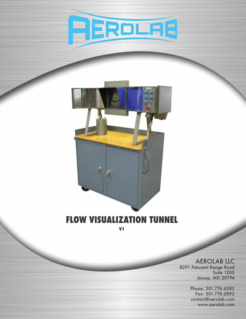
AEROLAB LLC 8291 Patuxent Range Road Suite 1200 Jessup, MD 20794 Phone: 301.776.6585 Fax: 301.776.2892 [email protected] www.aerolab.com FLOW VISUALIZATION TUNNEL V1
Transcript of AeroLab Flow Visualization Tunnel Operation and Experiment ... LAB Flow Visualization Tunnel ......
AEROLAB LLC8291 Patuxent Range Road
Suite 1200Jessup, MD 20794
Phone: 301.776.6585Fax: 301.776.2892
FLOW VISUALIZATION TUNNELV1

Flow Visualization TunnelV1
TABLE OF CONTENTS
Introduction 3
Description 3
Tunnel Overview 5Main Control Panel 6Model Operation and Experiment Suggestions 7 Airfoil with Blown Flap 7 Airfoil with Vacuum Holes 7 Airfoil for Student Experimentation 7 Airfpoil with Tangential Blowing Slots 8 Venturi 8 Circular Cylinder (Spin Model) 8 Delta Wing 8
Example Images 9
www.aerolab.com | 301.776.6585 2

www.aerolab.com | 301.776.6585 3
Flow Visualization TunnelV1
INTRODUCTION
The shape of an object moving through a fl uid has a major infl uence on the way the fl uid reacts. Using the AERO-LAB Flow Visualization Tunnel (FVT), students can see fi rsthand the fl ow of air over objects such as airfoils, wings, cylinders and other aerodynamic shapes.
While the AEROLAB Flow Visualization Tunnel is great for group demonstrations, itʼs also intended for hands-on student experimentation. Students can change pitch angles, defl ect fl aps, rotate circular cylinders and apply vacu-um or blowing to improve aerodynamic performance. Hands-on activities motivate learners because the effects of their adjustments are immediate and obvious.
DESCRIPTION
Wind Tunnel• Length: 53 inches (1.35m)• Height: 28.5 inches (72cm)• Width: 17 inches (43cm)
Cabinet:• Height: 37 inches (94cm)• Width: 45.5 inches (1.16cm)• Depth: 24 inches (61cm)
Power requirements:115 VAC 60 Hz ONLY, minimum 15 Amp circuit, international use requires a transformer.
Flow visualization tunnels, in particular, require exceptionally smooth, steady airfl ow. This quality of airfl ow is aerodynamically termed laminar fl ow. Laminar fl ow contains no eddies or other types of turbulence. Turbulence is undesirable because it diffuses the injected water vapor lines causing them to lose defi nition and appear fuzzy.
In general, laminar fl ow is not easy to generate and diffi cult to maintain. Two factors promote laminar fl ow: a carefully designed inlet bell mouth (known as the contraction) and an effective honeycomb fl ow straightener. The AEROLAB Flow Visualization Tunnel design includes a large-area-ratio (inlet to outlet) contraction and engineered aluminum honeycomb. The honeycomb provides approximately 7700 hexagonal channels, 7 inches in length and 1/8 inch across fl ats (Aspect Ratio 56). Honeycomb is also employed at the exit of the model area to ensure laminar fl ow.
Vaporized water (created by an ultrasonic atomizer) is introduced in streaklines spaced 0.25 inches (6.35mm) apart through a special rake. The rake is located near the exit of the contraction. The ultrasonic atomizer is housed in an enclosure directly below the smoke rake. During prolonged use, water vapor condenses in the vapor line. To remove the water droplets and restore vapor fl ow, the control panel has a purge button.
Flow Visualization TunnelV1
www.aerolab.com | 301.776.6585 4
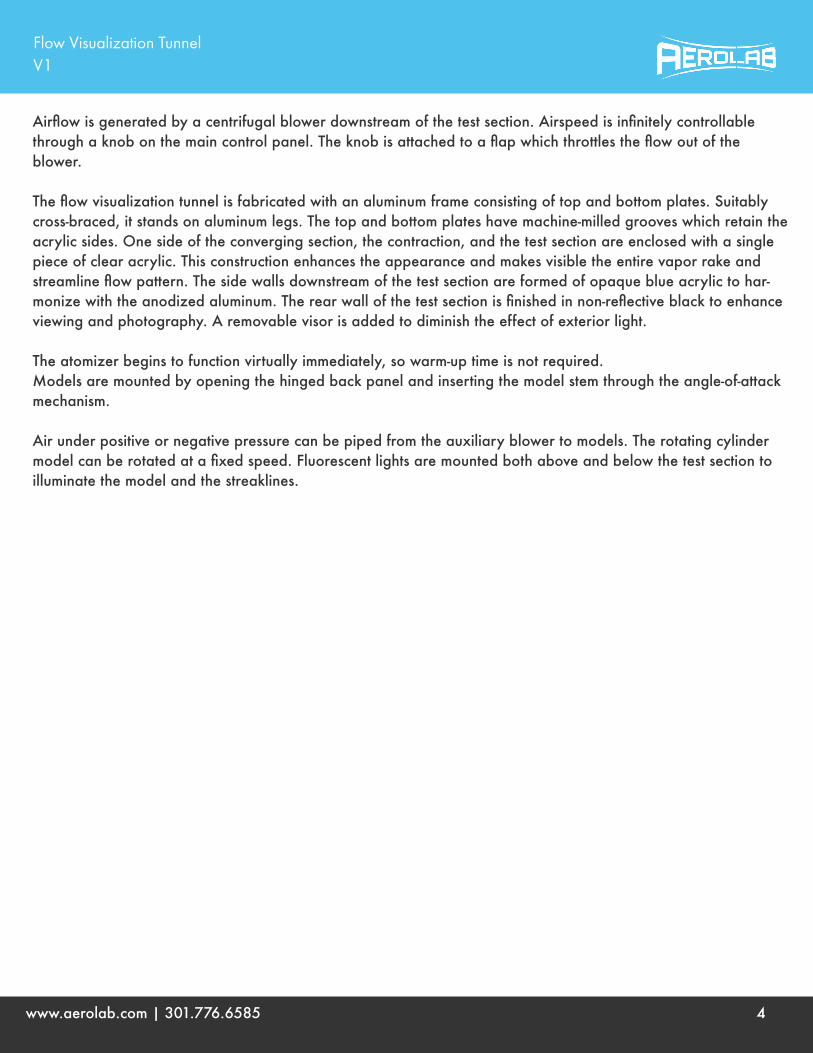
Airfl ow is generated by a centrifugal blower downstream of the test section. Airspeed is infi nitely controllable through a knob on the main control panel. The knob is attached to a fl ap which throttles the fl ow out of theblower.
The fl ow visualization tunnel is fabricated with an aluminum frame consisting of top and bottom plates. Suitably cross-braced, it stands on aluminum legs. The top and bottom plates have machine-milled grooves which retain the acrylic sides. One side of the converging section, the contraction, and the test section are enclosed with a single piece of clear acrylic. This construction enhances the appearance and makes visible the entire vapor rake and streamline fl ow pattern. The side walls downstream of the test section are formed of opaque blue acrylic to har-monize with the anodized aluminum. The rear wall of the test section is fi nished in non-refl ective black to enhance viewing and photography. A removable visor is added to diminish the effect of exterior light.
The atomizer begins to function virtually immediately, so warm-up time is not required. Models are mounted by opening the hinged back panel and inserting the model stem through the angle-of-attack mechanism.
Air under positive or negative pressure can be piped from the auxiliary blower to models. The rotating cylinder model can be rotated at a fi xed speed. Fluorescent lights are mounted both above and below the test section to illuminate the model and the streaklines.

Flow Visualization TunnelV1
www.aerolab.com | 301.776.6585 5
Tunnel Overview

Flow Visualization TunnelV1
www.aerolab.com | 301.776.6585 6
Main Control Panel
The POWER button is the main switch for the tunnel. Nothing can operate unless this switch is engaged. The air compressor (located sinside the cabinet) will run for a short period of time and the test section lights (top and bottom) will turn on when this button is activated.
The FAN button activates the wind tunnel fan.
The SMOKE button activates the atomizer.
The MOTOR button activates the cylinder electric motor.
The VACUUM button activates the auxiliary blower. The blower provides pressurized air and/or vacuum to the vacuum/blowing models.
The PURGE button provides a short blast of air to the vapor rake. This blast of air clears the rake of collected water droplets.

Flow Visualization TunnelV1
www.aerolab.com | 301.776.6585 7
The AIR SPEED knob (located on the right side of the FVT) changes the wind tunnel airspeed. Turn the knob clockwise to slow the fl ow or counterclockwise to speed it up.
Model Operation and Experiment Suggestions
Note - Because the airfoil models span the test area (they go from wall to wall), air is forced to move in only two dimensions (it cannot fl ow sideways to go around the ends of the models). This type of fl ow is termed two-dimensional.
Airfoil with Blown FlapThe Flap Model is intended to be used with and without blowing – note the slot just in front of the fl ap hinge on the top of the airfoil. The fl ap can be adjusted down or up. The model demonstrates the Coanda Effect when used with blow-ing. The Coanda Effect is used to increase high angle-of-attack performance. The intensity of the blowing should be adjusted to the lowest possible setting to achieve the desired result. The Boeing C-17 Globemaster III employs blown fl aps to increase performance.
Airfoil with Vacuum HolesVacuum applied to the top surface of a wing can increase high angle-of-attack performance. The Airfoil with Vacuum Holes serves to demonstrate this phe-nomenon. The intensity of the vacuum should be adjusted to the lowest possible setting to achieve the desired result. As an added experiment, use cellophane tape to partially or fully close holes and observe the result.
Airfoil for Student ExperimentationA large chamber has been cut into the top surface of the student experimenta-tion airfoil. The chamber can be covered with tape or paper and holes or slots can be opened to experiment with the application of blowing or vacuum.

Flow Visualization TunnelV1
www.aerolab.com | 301.776.6585 8
Airfoil with Tangential Blowing SlotsThe Flap Model is intended to be used with and without blowing – note the slot just in front of the fl ap hinge on the top of the airfoil. The fl ap can be adjusted down or up. The model demonstrates the Coanda Effect when used with blowing. The Coanda Effect is used to increase high angle-of-attack performance. The intensity of the blowing should be adjusted to the lowest possible setting to achieve the desired result. The Boeing C-17 Globemaster III employs blown fl aps to increase performance.
VenturiThe Venturi model serves to demonstrate the effect of a converging duct on moving air. Observe the streaklines as they pass through the model. Change the pitch angle of the model and observe the streaklines.
Circular Cylinder (Spin Model)The Circular Cylinder serves to demonstrate the Magnus Effect. Operate the tunnel with and without the cylinder spinning. Note the direction of the spin and the effect on the streak lines. By observing the vapor lines, what is happening and why.
Note - The delta and rectangular wing models allow air to fl ow around them just as it would on an actual air-craft. This is termed three-dimensional fl ow because the air is allowed to move in all three dimensions.
Delta WingThe delta wing model serves to demonstrate the vortices generated by such a wing design. The wingʼs angle of attack can be adjusted by gently twisting the wing on the mounting post. Also, change the yaw, or side-slip, angle of the model by means of the model mount and observe the result. Discuss the advantages of a delta-wing aircraft. What is the benefi t of the obvious vortices generated on the top of the wing?
Rectangular WingThe rectangular wing model serves to demonstrate the vortices generated by such a wing design. The wingʼs angle of attack can be adjusted by gently twisting the wing on the mounting post. Discuss the vortices – How do they affect the performance of the wing?

Flow Visualization TunnelV1
www.aerolab.com | 301.776.6585 9
EXAMPLE IMAGES
Airfoil with Blown Flap
Without Blowing
With Blowing (No Change in Pitch Angle or Flap Defl ection)

Flow Visualization TunnelV1
www.aerolab.com | 301.776.6585 10
Airfoil with Vacuum Holes
Without Vacuum
With Vacuum (No Change in Pitch Angle)

Flow Visualization TunnelV1
www.aerolab.com | 301.776.6585 11
Airfoil with Tangential Blowing Slots
Without Blowing
With Blowing (No Change in Pitch Angle)

Flow Visualization TunnelV1
www.aerolab.com | 301.776.6585 12
Circular Cylinder (Spin Model)
Without Spinning (Motor Off)
With Spinning (Motor On)

Flow Visualization TunnelV1
www.aerolab.com | 301.776.6585 13
Delta Wing
Rectangular Wing

Flow Visualization TunnelV1
www.aerolab.com | 301.776.6585 14
Venturi