Aerohive Branch on Demand
37
Aerohive Branch on Demand Delivering Enterprise Access and Network Security Anywhere Users Go 5.0r3 Evaluation Guide
Transcript of Aerohive Branch on Demand

Aerohive Branch on Demand
Delivering Enterprise Access and Network Security Anywhere Users Go
5.0r3 Evaluation Guide

Table of Contents
Aerohive Branch on Demand ................................................................................................. 1
Introduction .............................................................................................................................. 3
Initial Setup ............................................................................................................................... 4
Configure Branch Office Wireless and Wired LAN Policy ..................................................... 8
Test Branch Office Wireless and Routing Policy .................................................................. 25
Web Filtering with Websense ................................................................................................ 29
USB 3G/4G LTE Connectivity ................................................................................................. 33
And There Is More… .............................................................................................................. 36

Branch On Demand Evaluation Guide
Copyright ©2012, Aerohive Networks, Inc. 3
Introduction
Aerohive’s Branch on Demand solution enables enterprises to readily deliver robust Layer 2-7 corporate policy enforcement, enterprise class network visibility, and remote remediation capabilities to both branch office networks and teleworkers. Comprised of Aerohive’s BR Series branch router platforms, HiveOS router capabilities, the Cloud VPN Gateway, and the Aerohive Cloud Services Platform, Branch on Demand can be deployed with minimal effort, and scaled to a network of hundreds or thousands of Aerohive devices, delivering enterprise-class, secured connectivity to the corporate network from both branch offices and telecommuter sites. When utilizing Aerohive’s cloud-based management platform, HiveManager Online, IT administrators can manage their Branch Router and Wi-Fi infrastructure without having to purchase or deploy an on-premise network management system. A company can purchase Aerohive Routers, connect these devices to an Internet-accessible network connection anywhere in the world, and the Aerohive devices will automatically locate and connect to the user’s HiveManager Online account. Through the use of auto-provisioning profiles, HiveManager Online can then automatically push a configuration profile to the Aerohive device – lighting up corporate and guest Wi-Fi network settings, multiple LAN port access policies, web content security filtering and policy controls, IPsec VPN tunnels, and much more - while requiring no interaction from either the administrator or end user beyond plugging the device into power and an internet connection. Alternately, customers that prefer an on-premise management solution can opt for Aerohive’s HiveManager, delivered as either a virtual appliance or a hardware appliance. HiveManager is deployed in the customer’s datacenter, providing the same level of control and visibility over corporate wireless access points and branch routers. The following evaluation guide will walk a network administrator through a full-featured, multi-site deployment of 5.0r3-enabled Aerohive Branch Routers using HiveManager Online. This guide will show the administrator how to configure 1) a secured corporate wireless network and a guest wireless network, 2) authenticated wired connections and a dedicated guest Ethernet port, 3) network-wide Layer 3/Layer4 firewalls, 4) an IPsec VPN tunnel and concentrator to deliver secured corporate user access back to HQ, 5) integration with best-of-breed cloud-based web filtering solutions, and 6) 3G/4G USB-based internet connectivity. We will also demonstrate how to set up auto-provisioning profiles to easily deploy, provision, and configure Aerohive Routers in the field with no hands-on administration and no truck rolls. For those using on-premise HiveManager, these instructions apply just as well. To successfully complete the full setup for this demonstration, you will need:
• At least one Aerohive Branch Router(BR100, BR200) (running 5.0r3 or later) • A HiveManager Online account (running 5.0r3 or later) • A server running VMware ESXi (4.1 or later), used to deploy the Aerohive Cloud VPN Gateway • An activation code for the Aerohive Cloud VPN Gateway • A RADIUS server deployed on the corporate LAN, configured to support authentication from
wired and wireless clients. (This can be an Aerohive AP RADIUS server or a Branch Router RADIUS server if desired.)
• A Websense Cloud Web Security Account (We will show you how to sign up for a Websense trial account, but registration may take 24 hours, so you should get this process started right away (see the Web Filtering With Websense section.)
• A supported USB Modem (see the USB 3G/4G Connectivity section for list of supported devices) • One or more client devices that can be used to test access through the various networks we will
create.

4 Copyright ©2012, Aerohive Networks, Inc.
Initial Setup
When setting up Aerohive’s Branch on Demand solution for the first time, it is important to realize that the configuration methodology used in HiveManager is not intended for a single site deployment. Instead, think as if you were configuring a large number of branch office sites. For example, Figure 1 shows a corporate headquarters network (HQ) with three branch offices. Instead of having to configure each site individually, in HiveManager you can configure a single policy that is applied to all branch sites giving each site their own IP subnets, DHCP server service and settings, employee wireless and wired access with VPN access to corporate headquarters, guest networks, and web security. Figure 1 – Network Diagram for an HQ site with multiple branch offices.
When you are testing branch office scenarios, you can use one of the two pictures below as reference. Figure 2 shows a small branch office or teleworker site with a BR100. Figure 3 shows a small to medium size branch office with a BR200-WP that may have additional APs connected to it via wireless mesh, Ethernet if externally powered, or PoE connection directly from the BR200WP. In both cases the branch routers can be connected directly to a dedicated Ethernet link, cable modem, or a DSL modem using PPPoE. Optionally, wireless USB modems can be used for a primary connection or as a backup to Ethernet. When testing this solution, please be aware that the intent of the branch router solution is to have the router be the primary connection to the Internet to which all other devices connect through. Each router can provide DHCP service and uses network address port translation (NAPT) to translate internal traffic, not destined to an IPsec VPN, to its WAN IP address before sending the traffic to the Internet.

Branch On Demand Evaluation Guide
Copyright ©2012, Aerohive Networks, Inc. 5
Figure 2- Figure 3-
At this time, we will get started by guiding you through the initial setup of your HiveManager Online account, and through the process of connecting Aerohive Routers and APs to your network.
1. Please follow the steps outlined in the printed quickstart guide that comes with your router to get it connected to the internet, or from an Internet connected computer locate the guides online: BR200-WP Quickstart Guide http://www.aerohive.com/330000/docs/help/english/5.0r3/ref/BR200_QuickStart_330069-01.pdf BR100 Quickstart Guide http://www.aerohive.com/330000/docs/help/english/5.0r3/ref/BR100_QuickStart_330057-02.pdf Aerohive Routers may be installed behind existing firewalls/NAT routers (Figure 4) or connected directly to the live Internet through a DSL modem, cable modem, or router (Figure 5). All Aerohive Routers support DHCP, static IP addresses, and PPPoE for the WAN connection. Figure 4 Figure 5

6 Copyright ©2012, Aerohive Networks, Inc.
Aerohive Routers may also be deployed at a site in conjunction with Aerohive APs to provide additional wireless LAN coverage. In this situation, Aerohive APs should be deployed behind the Aerohive Router (Figure 6) or meshed with the Aerohive Router (Figure 7). Figure 6 Figure 7
Customers should not deploy Aerohive APs along side the Router, with ETH0 port of each device connected to the same subnet (Figure 8).
Figure 8
2. After your routers are attached to their Internet connection, open a web browser from your web-enabled management device (computer or tablet), and log in to MyHive - a secure site that lets you access HiveManager Online and the Redirector - at https://myhive.aerohive.com.
3. MyHive login information is emailed from the Aerohive account: [email protected]. Please search
your inbox for an email from: hmol

Branch On Demand Evaluation Guide
Copyright ©2012, Aerohive Networks, Inc. 7
Note: Please be aware that emails from HMOL may be located in your junk/SPAM email folder. If you do find the email in your junk/SPAM folder, please make sure to change your junk/SPAM email options to allow emails from aerohive.com.
4. Upon logging into MyHive, you will be presented
with the choice of going to HiveManager Online or the Redirector. Click the HiveManager Online button.
Optional: Click the Redirector button to view or enter new serial numbers for Aerohive Routers and APs that will attach to your HiveManager Online account. Aerohive automatically inputs this data as part of the order fulfillment process.
5. Read the End User License Agreement, then click Agree if you accept the agreement. Click the radio button next to Enterprise
Note: HiveManager Online must be set to Enterprise mode when managing an Aerohive Router.
6. Set the Hive Name to Aerohive_Evaluation
7. Set and confirm a New HiveManager Password.
<remember this password>
8. Set and confirm a new QuickStart SSID Password. <remember this password>
Note: The administrator password will be employed to log into HiveManager Online, to log into Aerohive devices via SSH or console cable, and as the PSK for the Virtual Access Console. The Quick Start Password is used as the PSK security key for an automatically generated QuickStart SSID.
9. Set the Time Zone appropriate for your location. 10. Click Continue.

8 Copyright ©2012, Aerohive Networks, Inc.
Configure Branch Office Wireless and Wired LAN Policy
In this demonstration, we will create and deploy a Wireless and Routing Network policy that includes both wired and wireless network settings that will be deployed to Branch Routers in the field. To gain remote access to the corporate network, corporate users accessing the network via wireless or a wired connection will authenticate using 802.1X to the corporate RADIUS server deployed at HQ. Access to the corporate network is provided through a VPN tunnel formed automatically between the Branch Router and the Cloud VPN Gateway, which is deployed in the corporate DMZ. For guest and home use, a wireless network secured with WPA2 Personal and a Use Policy Acceptance Captive Web Portal will be created, with a single LAN port dedicated to guest usage. Guest users will not have any access to the VPN tunnel or corporate data resources.
For this exercise, you will need to install and configure a Cloud VPN Gateway virtual appliance in order to establish an IPsec VPN between HQ and the Branch Routers. Detailed instructions on setting up VMware ESXi server and deploying a Cloud VPN Gateway virtual appliance can be found starting on page 48 of the Aerohive Deployment Guide.

Branch On Demand Evaluation Guide
Copyright ©2012, Aerohive Networks, Inc. 9
Create Network Policy To get started, you will need to create a network policy. A network policy is a collection of configuration settings that can be applied to multiple Aerohive APs and routers that share a common characteristic, such as being located at the same site or working together to connect multiple remote sites through VPN tunnels. Depending on the policy type, a Network Policy may reference a hive, one or more SSIDs, or LAN ports, as well as other configuration elements pertaining to networking, management services, QoS, and VPN tunneling.
The type of network policy you choose depends on the type of devices being deployed:
• A Wireless Only network policy is selected when you have an AP only deployment, or you require specific wireless policies for APs in a mixed AP and router deployment.
• A Wireless + Routing network policy is selected when you are managing routers, or APs behind routers that do not require different Network Policies than the router they connect through.
While you could create the Network Policy completely from scratch, HiveManager provides Quick Start policies for both Wireless Only and Wireless + Routing deployments that can be easily cloned for use with customer deployments. While we will not use the Quick Start SSID and LAN port settings during this evaluation, the Quick Start network policy also lights up numerous behind-the-scenes optimizations like the access console and QoS Classification settings that will be helpful to getting the routers running quickly and to ensure smooth operations thereafter.
1. From the Choose Network Policy panel, single-click or tap QuickStart-Wireless-Routing to highlight in
yellow, then click the gear icon and select Clone. 2. In the Clone Network Policy dialog box that appears, set the Name as Corp_Policy.
3. From the Hive drop-down box, select Aerohive_Evaluation . 4. Click the Clone button.

10 Copyright ©2012, Aerohive Networks, Inc.
I. Configure Wireless LAN
A. Create Two SSIDs (Corp + Guest)
1. You should find a QuickStart SSID and a QuickStart LAN Profile already populated in your new policy. Later, we will remove these objects from the policy for this evaluation.
2. Next to SSIDs, click Choose. The Choose SSIDs box will appear onscreen. 3. Click New, and you will be taken to the New SSID dialog. 4. Set the Profile Name as Corp_1X. Once you click elsewhere in the panel, the SSID field will auto-
populate with the same name. 5. To set the SSID Access Security, click the radio button next to WPA/WPA2 802.1X (Enterprise). 6. Click Save.
7. You will return to the Choose SSIDs
dialog box. Click New again to create a second network.
8. Set the Profile Name as Guests. Once you click elsewhere in the panel, the SSID field will auto-populate with the same name.
9. To set the SSID Access Security, click the radio button next to WPA/WPA2 PSK (Personal).
10. Set and confirm the PSK security Key Value. <remember this password>
11. Click the check box next to Enable Captive Web Portal.
12. Click Save.

Branch On Demand Evaluation Guide
Copyright ©2012, Aerohive Networks, Inc. 11
13. Single-click or tap Corp_1X and Guests as needed to ensure both new SSIDs are highlighted. Also ensure that QS-SSID is not highlighted, so it will not be included in the network policy.
14. With both new SSIDs selected, click OK.
15. When you return to the Configure Interface & User Access panel, both SSIDs require further configuration.
Note: Both SSIDs appear with blue link text, with additional links to the right shaded in rust. Rust colored links indicate additional configuration is required.
B. Configure Corporate SSID Corp_1X
We will start by configuring authentication for our Corporate Wireless Network Corp_1X.
1. Under Authentication, click <RADIUS
Settings>. 2. A Choose RADIUS dialog box will
appear. Click New. 3. Set the RADIUS Name as RADIUS1. 4. Uncheck the box next to Obtain an
Aerohive RADIUS server address through DHCP options.
5. In the IP Address/Domain Name drop down box, type in the IP address of the RADIUS server (for this example, 10.5.1.250).
6. Enter and Confirm the Shared Secret for the RADIUS server (for this example, aerohive123!).
7. Click Apply, then Save. Note: It is important to hit Apply before you hit Save. If you do not hit Apply, the RADIUS IP address will not be saved.

12 Copyright ©2012, Aerohive Networks, Inc.
8. In the User Profile column, click Add/Remove. 9. In the Choose User Profiles dialog box that
appears, click New. 10. For Name, type Corp_Users. 11. Set the Attribute Number as 10. 12. To create a new Network or VLAN-only
Assignment, click .
13. In the Networks > New box that appears onscreen, enter the Name CorpBranch_172.25.0.0/16.
14. From the VLAN drop-down box, select Create New VLAN then type 10.
15. To create a new DNS Service, click . 16. In the DNS Service > New box that appears, set
Name as Corp_DNS. 17. Select the radio button next to Use separate
DNS servers for internal and external domain name resolution. 18. For Internal Domains, enter your corporate Domain Name (in this example, ahdemo.local). 19. For DNS Server #1 enter the IP address of your corporate internal DNS server (in this example,
10.5.1.250).
Note: Aerohive Routers provide great flexibility when configuring DNS usage. Administrators may define both Internal and External DNS servers, as access to corporate resources may necessitate the use of an internal DNS server located on the other end of a VPN tunnel, while at the same time administrators may not want DNS lookups for basic Internet browsing to go through the tunnel. 20. For External, select the radio button for Resolve client name requests using the same DNS servers
as configured for the router. 21. Click Save. You will return to the Networks > New page, the DNS Service field will auto-populate
with the Corp_DNS object. 22. Ensure the Network Type drop down box is set to Internal Use. 23. Under Subnetworks, click New.

Branch On Demand Evaluation Guide
Copyright ©2012, Aerohive Networks, Inc. 13
24. For IP Network, type the network and mask of 172.25.0.0/16. 25. Slide the IP Address Allocation bar to the right until the number of Branches is 256.
Note: HiveManager Online does all the grunt work of assigning addresses across a large, distributed network. In the previous step, you simply gave us a large network (172.25.0.0) and a subnet mask (16, which is the same as 255.255.0.0). These two figures tell HiveManager Online the maximum amount of assignable network space available for the entire network. When you used the slider bar to set the number of branches (256), you told HiveManager Online to carve that very large chunk into 256 equal blocks, each of which has 253 IP addresses available for client use by client devices. One of those blocks will be assigned to each Aerohive Router using the subnetwork. If you need more branches, slide the IP Address Allocation bar further to the right, and HiveManager Online will allocate a smaller block of addresses to each Router. 26. Click the check box next to Enable DHCP Server.
27. With your mouse, grab the box at the left of the DHCP Address Pool slider bar. Slide the leftmost marker to the right until 10 addresses are reserved at Start. You can also use the arrow keys on your keyboard to fine tune this setting.
Note: This allows you to set aside a block of addresses that will not be included in the Aerohive Router’s DHCP scope and can therefore be statically assigned to servers or other devices. Notice that static addresses can be reserved from the beginning of the range, the end of the range, or both. 28. To have the Aerohive Router’s DHCP server assign a DNS suffix to clients, enter your Domain Name
(in this example, ahdemo.local). 29. Click Save. 30. Back on the Networks > New screen, click Save. 31. Back on the New User Profile panel, click Save. 32. Back in the Choose User Profiles box, notice the Corp_Users(10) object you just created has the
attribute number appended to the end, and is highlighted yellow. Click Save.

14 Copyright ©2012, Aerohive Networks, Inc.
This completes setup for the Corp_1X SSID. We will now configure the Guests SSID.
C. Configure Guest SSID Guests
1. In the row for the Guests SSID, in the Authentication column, click <CWP>. 2. In the Choose CWP box, click New.
3. Set the CWP Name as Guest_CWP. 4. From the Registration Type drop down box, select Use Policy Acceptance . 5. Click the Expand Arrow next to Captive Web Portal Success Page Settings. 6. To set the default action After a successful login, select the radio button for Redirect to the
initially requested page. 7. Click Save. The new Captive Web Portal will be automatically included for the Guests SSID. 8. In the User Profile column, click Add/Remove. 9. The Choose User Profiles box appears. Click New. 10. Set Name as Guest_Users. 11. Set Attribute Number to 100. 12. For Network or VLAN-only Assignment, click to create a new network.

Branch On Demand Evaluation Guide
Copyright ©2012, Aerohive Networks, Inc. 15
13. The Networks > New box will appear onscreen. Set Name to Guest_192.168.83.0/24. 14. From the VLAN drop-down box, select Create New VLAN then type 100. 15. In the DNS Service drop down box, select Aerohive_Evaulation .
Note: The Aerohive Router assigns itself via DHCP as the DNS Server for any client devices on the network, proxying for each of the configured DNS servers as defined in each Network. The Aerohive_Evaluation DNS object is created by default when the HiveManger Online account is first set up, utilizing the DNS server assigned to the Aerohive Router by an upstream DHCP server on its WAN connection. 16. For the Network Type drop down box, select Guest Use . 17. Leave the Guest Use Network address range as the default value of 192.168.83.0/24.
Note: Guest Use networks use a different addressing scheme than Internal Use networks. Whereas an Internal Use network is designed to be part of a larger, routable network utilizing IPsec VPN tunnels to build and secure the routes between the networks, the address range on Guest Use networks are the same on every Aerohive Router assigned the Network Policy. This network is a standard, non-routable NAT address range like that used by consumer grade home routers, and clients using this network will have no access to the VPN tunnel. While client devices using this network can only access the Internet, they will still be subject to Network Firewall policies or Web Filtering policies (Websense or Barracuda), as defined by the network administrator. 18. Ensure the check box next to Enable DHCP Server is checked. 19. Enter an NTP Server IP address. (For instance, 208.87.104.40 is the IP address for pool.ntp.org). 20. Click Save. 21. You will return to the New User Profile panel. Click Save. 22. In the Choose User Profiles box, ensure Guest_Users(100) is highlighted in yellow, then click Save.
16 Copyright ©2012, Aerohive Networks, Inc.
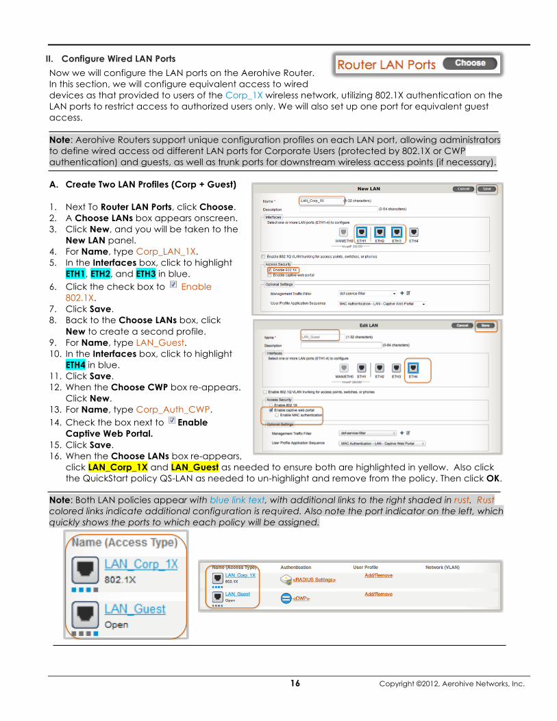
II. Configure Wired LAN Ports
Now we will configure the LAN ports on the Aerohive Router. In this section, we will configure equivalent access to wired devices as that provided to users of the Corp_1X wireless network, utilizing 802.1X authentication on the LAN ports to restrict access to authorized users only. We will also set up one port for equivalent guest access. Note: Aerohive Routers support unique configuration profiles on each LAN port, allowing administrators to define wired access od different LAN ports for Corporate Users (protected by 802.1X or CWP authentication) and guests, as well as trunk ports for downstream wireless access points (if necessary). A. Create Two LAN Profiles (Corp + Guest)
1. Next To Router LAN Ports, click Choose. 2. A Choose LANs box appears onscreen. 3. Click New, and you will be taken to the
New LAN panel. 4. For Name, type Corp_LAN_1X. 5. In the Interfaces box, click to highlight
ETH1, ETH2, and ETH3 in blue. 6. Click the check box to Enable
802.1X. 7. Click Save. 8. Back to the Choose LANs box, click
New to create a second profile. 9. For Name, type LAN_Guest. 10. In the Interfaces box, click to highlight
ETH4 in blue. 11. Click Save. 12. When the Choose CWP box re-appears.
Click New. 13. For Name, type Corp_Auth_CWP. 14. Check the box next to Enable
Captive Web Portal. 15. Click Save. 16. When the Choose LANs box re-appears,
click LAN_Corp_1X and LAN_Guest as needed to ensure both are highlighted in yellow. Also click the QuickStart policy QS-LAN as needed to un-highlight and remove from the policy. Then click OK.
Note: Both LAN policies appear with blue link text, with additional links to the right shaded in rust. Rust colored links indicate additional configuration is required. Also note the port indicator on the left, which quickly shows the ports to which each policy will be assigned.

Branch On Demand Evaluation Guide
Copyright ©2012, Aerohive Networks, Inc. 17
B. Configure Corporate LAN Policy LAN_Corp_1X 1. We will start by configuring our Corporate LAN Network LAN_Corp_1X. Because we are configuring
equivalent access to the network for wired and wireless users alike, we can re-use the RADIUS, User Profile, and Network settings that we created for the Corp_1X wireless network.
2. In the Authentication column, click <RADIUS Settings>. 3. In the Choose RADIUS dialog box, single-click RADIUS1 to highlight in yellow. This will set wired LAN
port 802.1X authentication to use the same RADIUS server previously configured. 4. Click OK. 5. In the User Profile column, click Add/Remove. 6. In the Choose User Profiles dialog box, single-click Corp_Users(10) to highlight in yellow. 7. Click Save. Note: Because the Corp_1X SSID and the LAN_Corp_1X LAN profile utilize the same User Profile and Network allocation, clients of both networks will be assigned addresses from the same subnetwork.
This completes setup for the LAN_Corp_1X Router LAN Port profile. We will now configure the LAN_Guest LAN profile. C. Configure Guest LAN Policy LAN_Guest
1. In the row for the LAN_Guest LAN profile, in the Authentication column, click <CWP>. 2. In the Choose CWP dialog box that appears, single-click Guest_CWP to highlight in yellow. 3. Click OK. 4. In the User Profile column,
click Add/Remove. 5. In the Choose User Profiles
dialog box, single-click Guest_Users(100) to highlight in yellow.
6. Click Save. Note: Because the Guests SSID and the LAN_Guest LAN profile utilize the same User Profile and Network allocation, clients of both networks will be assigned addresses from the same subnetwork.
III. Management Settings
1. The Aerohive_Evaluation Management Network object defines the default VLAN and subnetwork
used for communications between Aerohive devices and other network components. The default Management VLAN is 4094, and the default subnetwork allocation range is 172.18.0.0/16, supporting 512 branches.
2. The default Native (untagged) VLAN is VLAN 1. Note: Each Aerohive device is assigned an address in the 172.18.0.0/16 range. It is this IP address that will communicate with the RADIUS server in our example. Make sure your RADIUS server is configured to accept requests from the 172.18.0.0/16 address range.

18 Copyright ©2012, Aerohive Networks, Inc.
IV. Router Firewall
The router firewall is more than just a stateful IP-based firewall. The network administrator can assign router firewall rules based on traffic sourced from an IP Network, Network Object, IP Range, User Profile, VPN, or IP Wildcard, or hostname, and similarly define rules for traffic destined to an IP Network, IP Range, Network Object, VPN, IP Wildcard, or Hostname. Administrators may configure stateful firewall policies that will automatically be applied to every Branch Router configured to use the network policy. This allows corporations to restrict remote user access to sensitive data applications and resources or likewise to restrict corporate access to resources at the Branch. 1. Next to Router Firewall, click Choose. 2. When the Choose Firewall box appears, click New. 3. When the Network Firewall Policies > New box appears, set the Policy name to Corp_User_FW. 4. Create the first rule using the Rule 1 settings in the chart below.
Rule 1 Rule 2 Source <any> <any> Destination IP Range IP Range 10.5.1.240-10.5.1.250 * 10.5.1.240-10.5.1.250 * Service HTTP HTTPS Action Deny Deny Logging Disable Disable
* Note: In this demonstration network, there are webservers running on machines with IP addresses from 10.5.1.240 to 10.5.1.250. We will walk you through setting up policies to deny access from clients attached to Branch Routers to this webserver on HTTP (TCP Port 80) and HTTPS (TCP 443). Please make sure to adjust the IP address used in the rules to reflect your corporate network addressing.
5. Once you create the first rule, click Apply. 6. To create a second rule, click New. 7. Create the second rule using the Rule 2 settings in the chart above. 8. Click Apply.
Note: Rules are enforced from the top down, with a default rule applied at the end to either permit or deny all. You can easily reorder the rules created from this screen. Using your mouse, simply click and drag a rule to a different spot in the list.
9. Once the rules are in the preferred order, click Save.

Branch On Demand Evaluation Guide
Copyright ©2012, Aerohive Networks, Inc. 19
V. Layer 3 IPsec VPN
HiveManager Online and HiveOS make it incredibly easy to configure and deploy route-based IPsec tunnels between Aerohive Branch Routers and Aerohive’s VPN concentrator, the Cloud VPN Gateway. Unlike software-based VPN solutions that require VPN clients be installed on the clients themselves, a Branch Router with an established IPsec VPN tunnel allows multiple types of devices to connect through a secure SSID or authenticated LAN connection to the Router, which tunnels their traffic to the corporate network via the Cloud VPN Gateway. There is no need to install and license VPN client software for all end user devices, nor is there any need to manually create and manage IPsec client credentials. 1. Next to Layer 3 IPsec VPN, click Choose 2. In the Choose VPN Profile box, click New. 3. In the New VPN Service panel that
appears, set the Profile Name to Corp_VPN.
4. Ensure the radio button for Layer 3 IPsec VPN is selected.
5. Under VPN Gateway Settings, select your
Cloud VPN Gateway from the VPN Gateway drop-down box.
Note: To appear in this drop-down list, the Cloud VPN Gateway must be activated and must have established a CAPWAP connection to HiveManager Online.
6. Set the External IP Address.
The external IP address is the public-facing address of the Cloud VPN Gateway that Branch Routers can contact from the Internet. If a network firewall performs NAT for a Cloud VPN Gateway in the DMZ, then enter the external IP address that the firewall maps to the IP address of the Cloud VPN Gateway’s eth0 interface. If the firewall does not perform NAT, then enter the Cloud VPN Gateway’s eth0 IP address.
7. For Default Tunnel Policy, ensure Route only internal traffic through the VPN tunnel is selected. 8. Click Apply, then click Save.
We have now created our VPN policy, connecting every Branch Router using the Network Policy to the HQ corporate network.

20 Copyright ©2012, Aerohive Networks, Inc.
VI. Additional Settings
Ensuring the correct time and DNS settings are applied to all Branch Routers across the Aerohive network is essential for smooth operation. There is a great wealth of other features to explore here as well, but we will concentrate on NTP and DNS for this evaluation.
1. Next to Additional Settings, click Modify. 2. Expand Management Server Settings. 3. Because we cloned the Quick Start template at the start of the exercise. the NTP Server drop-down
box should be prepopulated with Aerohive_Evaluation . 4. From the DNS Server drop-down box, select Aerohive_Evaluation . 5. Click Save.
We have completed setting up our Branch Office Wireless and Routing Network Policy. Click the Continue button, which is located in the black Configure Interface & User Access bar towards the top of the screen. This will save your Network Policy and take you to the Configure & Update Devices panel.

Branch On Demand Evaluation Guide
Copyright ©2012, Aerohive Networks, Inc. 21
VII. Configure the Cloud VPN Gateway
1. From the Configure & Update Devices panel, click on the Cloud VPN Gateway’s blue link (AH-172a51), in this example).
2. Edit the Host Name, adding CVG- before the existing name (CVG-AH-172a51, in this example). 3. Configure the Eth0 (WAN) and Eth1 (LAN) IP address/subnet mask for your network, as well as the
Default Gateway for the WAN connection. Note: In this example, WAN = 1.1.1.10/24, Default Gateway = 1.1.1.1, LAN = 10.5.1.10/24. The addresses you input must match your network address plan. In this example, the WAN is using a public IP address with no NAT used for the Cloud VPN Gateway. If NAT is used, the Cloud VPN Gateway’s WAN address will be a private IP address, and the public NAT address for the Cloud VPN Gateway needs to be configured in the VPN policy.
4. Define the internal networks and routes that Cloud VPN Gateway needs to know about.
Administrators must tell the Cloud VPN Gateway about all internal networks and routes accessible via the VPN. The Cloud VPN Gateway will propagate this network and route information out to the Branch Routers, so client traffic originating from branch networks can be successfully routed to the correct destination. The Cloud VPN Gateway supports dynamic routing (either OSPF or RIPv2) or administrators can define static routes.
Option 1 – Configure Dynamic Routing i. Aerohive supports OSPF and RIPv2 routing protocols, allowing the CVG to automatically pick up
routes advertised by other routers on the internal network. ii. To enable, check the box for Enable Dynamic Routing. iii. From the drop-down box, select either OSPF or RIPv2 based on the routing protocol supported
on your internal network.
iv. Mark the check box for the Ethernet port that will receive the route advertisements, either Eth0 (WAN) or Eth1 (LAN).
Note: Cloud VPN Gateways may be deployed in one-arm or two-arm modes, utilizing either one or two Ethernet ports. When one-arm mode is employed, the Eth1 port will not be used. Therefore, the route advertisement will be received on Eth0. In two-arm mode, Eth1 will be the port used to receive route advertisements.

22 Copyright ©2012, Aerohive Networks, Inc.
Option 2 – Static Routing i. For networks without dynamic routing on the internal network or those that have only a single
subnet behind the Cloud VPN Gateway, administrators may configure static routes and Internal Networks.
ii. For this demo, the only subnet on the corporate LAN behind the Cloud VPN Gateway is 10.5.1.0/255.255.255.0. By default, the subnet connected to each Ethernet port of the CVG is automatically included in the routing table to be distributed to Aerohive Routers.
iii. To add additional networks, click the arrow to expand Internal Networks.
iv. Add the correct internal Network for your network (in this example, 10.5.1.0) and Netmask (255.255.255.0).
v. Click Apply. vi. For networks with additional internal subnets, you will need to add and define additional
Internal Networks, and also create new Static Routes for each additional internal network, defining the Destination IP subnet, Netmask, and Gateway. You can also mark each static route that will be distributed to Branch Routers.
5. Once Internal Networks and routes are defined, click Save for the Edit Device panel. 6. To upload the configuration to your Cloud VPN Gateway, check the box next to your Cloud
VPN Gateway then click Upload. 7. After a moment, upload will complete. Click Reboot, then click Yes to confirm the reboot. After the Cloud VPN Gateway completes the reboot cycle, it will be ready to accept connections as Aerohive Routers come online in the field.

Branch On Demand Evaluation Guide
Copyright ©2012, Aerohive Networks, Inc. 23
VIII. Auto Provisioning & Plugging in the Aerohive Device Whether you have dozens or thousands of devices in your Aerohive network, auto provisioning makes it simple to configure APs and Branch Routers without manual intervention from the user or the administrator, no matter where in the world the device is connected. In this demonstration, we will set up Auto Provisioning profiles that will automatically deliver our Network Policy to both BR100 and BR200 models of Aerohive Branch Routers. Note: If testing with a BR200-WP or an Aerohive AP330 or AP350, please adjust the instructions below accordingly for your correct device model. 1. Towards the top left of the screen, click Show Nav. When the Policy
Configuration sidebar appears, click Auto Provisioning. 2. To set up the new Auto Provisioning policy for the BR100, click New. 3. Check Enable HiveAP Auto Provisioning. 4. For Name, type Corp_BR100 .
5. For Device Model, select BR100 from the drop-down menu. Note: When provisioning an Aerohive AP330 or AP350 as a Branch Router, you will need to configure an additional setting. To ensure that the AP330/AP350 will be configured as a Router instead of an Access Point, select Router from the Device Type drop-down box.
6. For the Network Policy drop-down, select Corp_Policy . 7. Expand Advanced Settings. 8. Check Upload configuration
automatically. 9. Check Reboot after uploading. 10. Click Save. 11. To create the BR200 Auto Provisioning
policy, click New. 12. Check Enable HiveAP Auto Provisioning. 13. For Name, type Corp_BR200 .
14. For Device Model, select BR100 from the drop-down menu.
15. For the Network Policy drop-down, select
Corp_Policy . 16. Expand Advanced Settings. 17. Check Upload configuration
automatically. 18. Check Reboot after uploading. Note: You can also automatically upload the latest version of HiveOS to Aerohive devices as part of the Auto Provisioning process. Check Upload HiveOS upon device authentication, and select from the drop down list the desired image version for the device model.

24 Copyright ©2012, Aerohive Networks, Inc.
19. Click Save. Note: You can ensure an Auto Provisioning profile is only installed on approved or specified devices. Check Apply to devices with the following identification, then in the resulting box that appears, you can import and select a list of serial numbers for approved devices. 20. You may now connect your Aerohive device to the
network. Consult the Install Guide that comes in the box with the device for installation instructions. If the Aerohive device is already connected to HiveManager Online, you can go to Monitor > All Devices and remove the device from the New Devices list. After a moment, the device will be discovered again and auto provisioning will begin.
21. Once you connect the device to the Internet, grab a cup of coffee and wait about 10 minutes. After that time, the BR100 should be up and running. You can tell that the device is operating correctly if the white LED shines steadily on the front of the device.
22. You can check the progress of your BR100’s configuration from HiveManager Online by browsing to Monitor > Device Update Results.

Branch On Demand Evaluation Guide
Copyright ©2012, Aerohive Networks, Inc. 25
Test Branch Office Wireless and Routing Policy
I. Test The Corp_1X SSID
1. To test the new corporate Wi-Fi network, attach to the Corp_1X SSID.
2. Enter valid username and password that is already configured for use on the RADIUS server.
3. Accept the RADIUS server certificate, if necessary.
4. Notice the IP address assigned to the device, and you will find that the client has been assigned an address in the 172.25.0.0/16 block we created earlier. The client has also been assigned the search domain you specified earlier.
5. From the client, ping a device on your corporate network to ensure the VPN tunnels work.
6. Using a web browser on your client, attempt to browse to the web server blocked by the firewall rule you created earlier.
II. Test The Guests SSID
1. To test the new guest network, attach to the Guests SSID. 2. Input the PSK security key you defined earlier for the Guests SSID. 3. Notice the IP address assigned to the client address will be in the 192.168.83.0/24 range you defined
earlier. 4. Using a web browser on your client device, attempt to browse to any website. 5. An Acceptable Use Policy Captive Web Portal appears on screen. Read the Terms Of Use and click
Accept. 6. After a few seconds, the browser will redirect to the site you first attempted to contact. 7. Try to ping an address on your protected corporate LAN. You will find that Guest users have no
access to the VPN tunnel.

26 Copyright ©2012, Aerohive Networks, Inc.
III. Test the LAN_Corp_1X LAN Policy 1. Connect a computer to ETH1, ETH2, or ETH3 on your
Aerohive device. 2. Authenticate to the network using your RADIUS
credentials. 3. Notice the IP address assigned to the device, and you
will find that the client has been assigned an address in the 172.25.0.0/16 block we created earlier. The client has also been assigned the search domain you specified earlier.
4. From the client, ping a device on your corporate network to ensure the VPN tunnels work.
5. Using a web browser on your client, attempt to browse to the web server blocked by the firewall rule you created earlier.
IV. Test The LAN_Guests LAN Policy 1. To test the LAN port guest network, attach a
computer to ETH4. 2. Notice the IP address assigned to the client
address will be in the 192.168.83.0/24 range you defined earlier.
3. Using a web browser on your client device, attempt to browse to any website. 4. An Acceptable Use Policy Captive Web Portal appears on screen. Read the Terms Of Use and click
Accept. 5. After a few seconds, the browser will redirect to the site you first attempted to contact. 6. Try to ping an address on your protected corporate LAN. You will find that Guest users have no
access to the VPN tunnel.

Branch On Demand Evaluation Guide
Copyright ©2012, Aerohive Networks, Inc. 27
V. HiveManager Online Tools
1. Active Clients - From HiveManager Online, you can view the various clients you have attached to your Branch Routers by browsing to Monitor > Clients > Active Clients.
Active Clients provides a customizable overview of every client currently attached to a managed Aerohive AP or Branch Router throughout the distributed network. For each attached client, this interface by default shows the Client Health Score, client addresses (both IP and MAC), host name (as detected by the Aerohive device), location (as defined by assigned topology map of the associated AP or Branch Router), session start time, connected Aerohive device, SSID/Security Object in use, Interface (WiFi or LAN), plus Client Authentication method and Wi-Fi channel, if applicable. You can also
add columns to view VLAN, User Attribute, Association Mode and others by clicking and adding those columns to the view.
For each client, HiveManager Online also presents a visually discernible and an easy to understand Client Health Score that quantifies the radio link quality, network connectivity, and throughput for applications provided by the associated Aerohive device. The score is presented using a color-coded system to show individual (for each metric) and overall scores. Green means that a score is good, yellow means that the score is passable but could be better, and red means that there is a problem needing attention. The overall score is equal to the lowest of three measurements.
- The radio link score is based on a client's data rates (applicable to wireless clients). - The network connectivity score is derived based on whether the client can obtain an IP address
through DHCP. - The application score is based on how well a client's SLA (service level agreement) is met.
2. All Devices You can view all the Aerohive APs, Branch Routers, and Cloud VPN Gateways that are managed by HiveManager Online by browsing to Monitor > Devices > All Devices. You can also view Aerohive devices by category, as there are also separate views for APs, Branch Routers, and VPN Gateways.

28 Copyright ©2012, Aerohive Networks, Inc.
By default, you can audit the status of your Aerohive devices to ensure they are running an up-to-date version of their configuration profile. Indicates that a device is up to date, while indicates that a device requires an update to its configuration. You can see exactly what updates are required by clicking on to perform a configuration audit.
The All Devices screen also shows the status of the VPN connection. The symbol indicates that the Cloud VPN Gateway is online and ready to accept VPN connections from Branch Routers, while the symbol indicates that a Branch Router has successfully established a tunnel with a Cloud VPN Gateway. You can also view the status of the Aerohive device’s CAPWAP connection to HiveManager Online through the Connection column. The symbol indicates a healthy, active connection between the
Aerohive device and HiveManager Online, while indicates a device is offline or unable to contact HiveManager Online. 3. VPN Topology If you browse to Monitor > Devices > VPN Gateways, then click on the blue link for an active Cloud VPN Gateway, you can view detailed information about your VPN. The default view includes graphs depicting System CPU and Memory usage, VPN availability, and WAN throughput. You can also view uptime information for every VPN tunnel in the distributed network. If you click on the VPN Topology link, you can also view a graphical depiction of the tunnels in your network.
Note: Some of the graphs on this page currently require Adobe Flash is installed on your management PC.

Branch On Demand Evaluation Guide
Copyright ©2012, Aerohive Networks, Inc. 29
Web Filtering with Websense
Aerohive’s Cloud Proxy (N-Way Split Tunneling) ensures the integrity of web traffic originating from telecommuter locations and branch offices through seamless integration with best-of-breed cloud-based security vendors, such as Websense and Barracuda Networks. Through Cloud Proxy, network administrators can deliver branch offices and remote users HQ-like levels of protection against web threats, unwanted or illicit content, and productivity-sapping web sites and services, while mission-critical, known-good traffic destined for approved sites like Salesforce.com can be whitelisted from the filtering service. Aerohive Routers forward traffic with client identity to the security partner, allowing administrators to define user or group-based filtering policies, with no need for users to log in to the filtering service and no need for any client device configuration at all.
To demonstrate the ease and flexibility of web filtering deployment, we will walk you through the process of configuring Aerohive Branch Routers for use with Websense Hosted Web Security. I. Sign up For Free Websense Trial and Enable Aerohive’s Websense Services
1. From HiveManager Online, navigate to Home > Administration > HiveManager Services 2. Check the box next to Websense Service Settings.

30 Copyright ©2012, Aerohive Networks, Inc.
3. Click the onscreen link (or click here) to browse to Websense’s sign up page. 4. From the screen that appears, download the Websense Hosted Web Security Getting Started Guide
from the link on the right side of the screen (or click here.) 5. If you already have a Websense account, log in. Otherwise, click Register and follow the steps to
enter your details, then return to the Evaluate page and click free evaluation again. 6. Answer the registration questions, then click Continue. 7. Read the terms and conditions by clicking on the link, then check the box confirming you have read
them and click Confirm. 8. After you click Confirm, you receive a confirmation email telling you how to proceed. It could take
up to 24 hours to receive confirmation. 9. The confirmation email will contain your login information for the Websense filtering service. You
may login with these credentials at https://www.mailcontrol.com/login/login_submit.mhtml. The Websense free evaluation is good for 30 days.
10. To obtain the security key and Account ID needed to link your Aerohive setup to your Websense services, click the Web Security button, then click Configuration Info. Copy both the Security Key and Account ID.
11. A new account will automatically be provisioned with a default profile which blocks access to certain categories of web sites (adult, drug related, gambling, etc.). The default policy also enables inline virus detection and application scanning. Consult the Websense Hosted Web Security Getting Started Guide for instructions on setting up a more complex web filtering policy.
12. Back in HiveManager Online, check Enable Websense Server Settings. 13. Enter the Account ID and Security Key you copied from the Websense interface. 14. Enter your Default Domain (in this example, ahdemo.local). The default domain is only used if users
do not authenticate to the network using a mechanism that requires a domain name for login. 15. Click Update to save these settings. Note: The default whitelist consists of a handful of sites known to deliver high volumes of known-safe web traffic (for instance, various Microsoft download sites like Windows Update). II. Configure Websense use for Corp_1X SSID and LAN_Corp_1X LAN Profile 1. Click Configuration from the yellow navigation bar, then highlight the Corp_Policy Network Policy.
Then click OK. 2. In the SSID section, find the Network (VLAN) column and click Corp_Branch_172.2… (10).

Branch On Demand Evaluation Guide
Copyright ©2012, Aerohive Networks, Inc. 31
3. In the Edit Network box that appears, select Websense from the Web Security drop-down box. 4. By default, if the connection between the Aerohive Router and the Websense filtering service is
broken, Aerohive Routers will drop all outbound HTTP and HTTPS traffic that is not white-listed or destined for the VPN tunnel. If you want to fail open in case that connection drops, click Permit all outbound HTTP and HTTPS traffic instead.
5. Click Save. 6. Notice the small red icon added to the network
object, indicating an active web filtering policy. Because the Corp_1X SSID and the LAN_Corp_1X LAN Profile share the same network, the LAN_Corp_1X LAN profile will automatically pick up these settings as well.
7. In the black Configure Interfaces & User Access bar, click Save. III. Create and Deploy a Custom Whitelist
1. Click blue Show Nav button in the top left of
the screen to reveal the Policy Configuration sidebar.
2. Browse to Advanced Configuration > Common Objects > Device Domain Objects.
3. Check the box for QS-WebSense_Whitelist and click Clone.
4. Set Object Name as Aerohive_Evaluation_Whitelist.
5. To add a custom domain name to the whitelist, click New.
6. Add a Domain Name (for this example, salesforce.com).
7. Click Apply, then repeat steps 5 and 6 for each domain you wish to add to the whitelist.
8. When you are done adding domains, click Save.
9. Navigate back to Home > Administration > HiveManager Services, then check the box next to Websense Server Settings.
10. From the Web Security Whitelist drop-down box, select Aerohive_Evaluation_Whitelist , then click Update.
32 Copyright ©2012, Aerohive Networks, Inc.
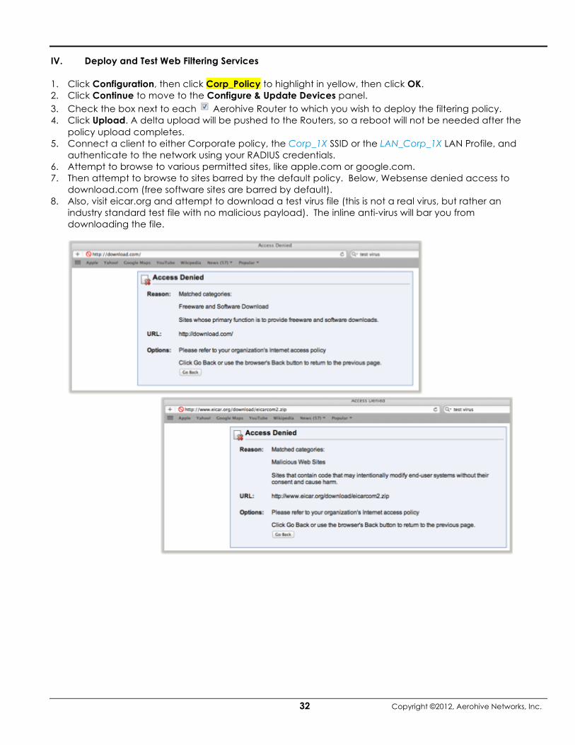
IV. Deploy and Test Web Filtering Services
1. Click Configuration, then click Corp_Policy to highlight in yellow, then click OK. 2. Click Continue to move to the Configure & Update Devices panel. 3. Check the box next to each Aerohive Router to which you wish to deploy the filtering policy. 4. Click Upload. A delta upload will be pushed to the Routers, so a reboot will not be needed after the
policy upload completes. 5. Connect a client to either Corporate policy, the Corp_1X SSID or the LAN_Corp_1X LAN Profile, and
authenticate to the network using your RADIUS credentials. 6. Attempt to browse to various permitted sites, like apple.com or google.com. 7. Then attempt to browse to sites barred by the default policy. Below, Websense denied access to
download.com (free software sites are barred by default). 8. Also, visit eicar.org and attempt to download a test virus file (this is not a real virus, but rather an
industry standard test file with no malicious payload). The inline anti-virus will bar you from downloading the file.

Branch On Demand Evaluation Guide
Copyright ©2012, Aerohive Networks, Inc. 33
USB 3G/4G LTE Connectivity
All Aerohive Branch Routers (BR100, BR200, BR200-WP, and the AP330/AP350 in router mode) can use a wireless USB modem for a WAN connection. The typical use of the USB modem is to act as a backup to the Eth0/WAN interface. You may also use the USB modem as the primary interface to the WAN with Eth0 as the backup WAN connection, or use the USB modem as the only WAN interface.
Note: When using a wireless USB modem on an Aerohive AP330 or AP350, you must connect the access point to an AC power source instead of using Power over Ethernet (PoE) to power the device. The BR100, BR200, and BR200-WP can not be powered via PoE and must always use an AC power source.
In this release, Aerohive supports the following modems:
• Sierra Wireless USBConnect 308, and Sierra Wireless Aircard 310U, 312U, 313U, and 320U to connect to a 3G/HSPA+ wireless network.
• Pantech UML290 to connect to a 4G (LTE) or 3G/EVDO Rev A. wireless network.
The dialup PPP settings (APN, dialup number, user ID, and password) for AT&T and Verizon are preconfigured for HiveManager Online and Aerohive devices. Due to the preconfigured settings, you can typically use a wireless USB modem for WAN connectivity without the need to configure anything extra as long as the following conditions are met:
• The modem is one of the models that Aerohive supports and has been previously activated.
• The wireless carrier provides adequate coverage where the branch router is deployed.
• The Aerohive device references a track IP profile with WAN connectivity testing enabled (this is configured and enabled by default).
When using International versions of the supported Sierra Wireless adapters, additional configuration will be required. Specifically, you will need to obtain the APN, dialup number, User ID, and password for the carrier in question, then input that data into HiveManager Online and push the configuration to the Aerohive Router.
• The international version of the Sierra Wireless USBConnect 308 is the AirCard 310U.
• The international versions of the Sierra Wireless AirCard 313U are the AirCard 312U and 320U.
You must activate any supported USB modem before the device may be used with an Aerohive Router. Activation may be completed in the store when you purchase the modem, or you might install software such as the Verizon VZAccess Manager on your computer, attach the modem to a USB port on your computer, and run the activation software yourself. In either case, try the modem first on your computer, preferably at the site where you plan on deploying the branch router. You can then confirm that the modem works properly and that there is adequate wireless network coverage at that location. Verizon Note: Out of the box, Aerohive supports the Pantech UML290 for use with Verizon’s LTE network. If Verizon LTE coverage is not available in your location, but Verizon EVDO Rev. A coverage is available, there is a workaround available to reprogram the modem to connect to Verizon’s EVDO network by default. For further information about the underlying issue and to download a workaround tool, check out http://www.evdoinfo.com/content/view/3492/64/. While Aerohive has successfully tested this workaround, we must note that this website and workaround tool are not affiliated with Aerohive in any way. Download and use the tool at your own risk.

34 Copyright ©2012, Aerohive Networks, Inc.
I. Configuring WAN Failover to the USB Modem
You can configure a router to use its Eth0 interface for its primary WAN connection and, if any issues with this connection arise, to fail over to a USB modem as its backup WAN connection. Loss of Layer 1 connectivity on the ETH0/WAN port or a WAN connectivity loss detected by IP tracking can trigger a failover. The failover from the Eth0/WAN interface to the USB modem can take about 30-45 seconds for full WAN and VPN connectivity to be restored, depending on the WAN link heartbeat settings employed. When failover to USB WAN occurs, the status LED on a BR100 changes from steady white, which indicates it has a CAPWAP connection to HiveManager Online through its Eth0/WAN interface, to flashing white, which indicate it is in a failover state and is using the wireless USB modem for its WAN link.
1. Connect a supported 3G/4G USB modems to the USB port of the Aerohive Router.
2. In the HiveManager Online GUI, click Configuration, then single-click or tap Corp_Policy to highlight in yellow, then click OK.
3. In the Configure Interface & User Access panel, click the Modify button next to Additional Settings,
expand Service Settings, choose QS-IP-Track-Router from the Track IP Group for router WAN connectivity drop-down list if it is not already chosen, and then click Save.
Note: The QS-IP-Track-Router profile tracks the default gateway for the branch router and two IP addresses. The only action the router will take if all targets become unresponsive is to fail over to the USB modem.
4. Back on the Configure Interface & User Access panel, click Continue. This will save your network policy and take you to the Configure & Update Devices panel.

Branch On Demand Evaluation Guide
Copyright ©2012, Aerohive Networks, Inc. 35
5. To view or change the default settings for the USB modem, click the host name of the Aerohive Router to which you will attach the USB modem.
6. Under Optional Settings, expand Interface and Network Settings.
7. In the Port Settings section, Eth0 defaults as the Primary WAN port with USB as Backup. You may reverse these roles, if you want 3G/4G to be the primary connection.
8. In the Wireless USB Modem Settings section, you will find the controls over 3G/4G connection settings and behaviors.
Note: When you select Connect as Needed, the branch router initiates a connection from its USB modem to the ISP only when there is a loss of network connectivity on its Eth0/WAN interface. When you select Always Stay Connected, the branch router is always connected through its USB modem to the ISP in anticipation of a failover. An advantage to connecting only when needed is that you can minimize the number of minutes that the branch router is on the 4G or 3G network as well as the number of data bytes it transmits. An advantage to always being connected is that the failover occurs faster because the dialup PPP connection is already established. Note: Use the AT&T Shockwave row to configure Sierra Wireless USB308 or 310U adapters. Use the AT&T Momentum row to configure Sierra Wireless 313U, 312U, and 320U adapters. Note: In late summer 2011, the AT&T network in the U.S. updated the SIM cards used in 3G/4G devices. SIMs obtained before September 2011 will work with APN = ISP.CINGULAR. SIMs obtained after September 2011 should use APN = broadband.
9. Click Save.
10. Check the box next to the Aerohive Router you wish to update then click Upload.
11. To test the failover and network connectivity through the USB modem, disconnect the Ethernet cable from the Eth0/WAN interface of the branch router, and then do the following:
• Wait a moment after disconnecting the cable and then check that the status LED flashes white.
• Check the Monitor > Devices > Branch Routers page to see if the device has a CAPWAP connection to HiveManager Online. It may take up to five minutes for the device to re-establish a CAPWAP connection with HiveManager.
• From a client connected to the branch router, ping 8.8.8.8 to see it can connect to devices on the Internet. Also verify that the VPN tunnel works correctly, if you are connected to the Corp_1X SSID or the wired Ethernet ports configured to use the LAN_Corp_1X LAN profile.
• From the same client, ping ntp1.aerohive.com to see the client can resolve DNS.
12. To return the WAN link to the Eth0/WAN interface, simply reconnect the Ethernet cable. The device will fail back about 12-15 seconds after the Eth0/WAN interface regains network connectivity. After a moment, the device reforms its CAPWAP connection with HiveManager Online.

36 Copyright ©2012, Aerohive Networks, Inc.
And There Is More…
This guide provided instructions how to deploy some common use cases using Aerohive APs, Branch Routers, and Cloud VPN Gateways when using Aerohive’s cloud-based management solution, HiveManager Online. There are still many possible scenarios, features, and functionality that we have not outlined in this document. For more details on how to configure an Aerohive network, check out the extensive help files, configuration guides, and training videos that can be accessed directly from HiveManager Online by clicking the Help Link found in the top right corner of the screen. We also highly recommend you browse to http://www.aerohive.com/support/technical-training to locate and schedule an Aerohive training session.

Branch On Demand Evaluation Guide
Copyright ©2012, Aerohive Networks, Inc. 37
About Aerohive Aerohive Networks reduces the cost and complexity of today’s networks with cloud-enabled, distributed Wi-Fi and routing solutions for enterprises and medium sized companies including branch offices and teleworkers. Aerohive’s award-winning cooperative control Wi-Fi architecture, public or private cloud-enabled network management, routing and VPN solutions eliminate costly controllers and single points of failure. This gives its customers mission critical reliability with granular security and policy enforcement and the ability to start small and expand without limitations. Aerohive was founded in 2006 and is headquartered in Sunnyvale, Calif. The company’s investors include Kleiner Perkins Caufield & Byers, Lightspeed Venture Partners, Northern Light Venture Capital and New Enterprise Associates, Inc. (NEA).
Corporate Headquarters EMEA Headquarters Aerohive Networks, Inc. Aerohive Networks Europe LTD 330 Gibraltar Drive Sequel House Sunnyvale, California 94089 USA The Hart Phone: 408.510.6100 Surrey, UK GU9 7HW Toll Free: 1.866.918.9918 +44 (0)1252 736590 Fax: 408.510.6199 Fax: +44 (0)1252711901 [email protected] www.aerohive.com