
Aerodynamic Design of the Vertical Takeoff Hopper Concept...
26
9 Aerodynamic Design of the Vertical Takeoff Hopper Concept of Future Launchers Preparatory Programme Giuseppe Pezzella Italian Aerospace Research Centre - CIRA, via Maiorise, Capua Italy 1. Introduction In the frame of the Future Launchers Preparatory Program, carried out by the European Space Agency, the vertical take-off (VTO) Hopper - reusable launch vehicle concept is investigated (Guédron, 2003) (Kauffmann, 2006). The VTO Hopper is a reusable, winged sub-orbital single stage vehicle, featuring a circular cross-section, designed for vertical take-off. The launch vehicle is composed of a reusable booster (the Hopper) and an expendable upper stage, mounted on top of it (Pezzella et al., 2009). After the staging at suborbital altitude (> 130 km), the reusable booster will follow a ballistic arc trajectory, will re-enter the Earth’s atmosphere, and will then perform a downrange landing (Pezzella et al., 2009). The upper stage will deliver a payload up to 8 Mg in geostationary transfer orbit. In this chapter the current aerodynamic analysis related to the launcher design is described. The goal was to define the aerodynamic data-base of the vehicle in order to provide the necessary input for the Flight Mechanics analysis. Different design approaches were adopted in this work. In fact, aerodynamic analysis has been performed starting from engineering based methods, in order to rapidly accomplish the preliminary aerodynamic database to generate a number of possible re-entry trajectories, able to fulfill the program requirements. To do these analyses, a three dimensional (3-D) panel methods code, based on the simplified Newtonian approach and local inclination methods typical of hypersonics, was employed (Bertin, 1994). Increasing the order of complexity, a number of detailed computational fluid dynamics (CFD) analyses have been carried out to more deeply characterize the hypersonic re-entry environment of the vehicle. To this end, 3-D Euler and Navier-Stokes numerical flowfield computations were performed at different Mach numbers and angles of attack, at the most critical flight conditions of the vehicle descent trajectory. In the chapter, qualitative summaries of the results are given for each aerodynamic force and moment coefficient as function of Mach number, Reynolds number and angle of attack. www.intechopen.com
Transcript of Aerodynamic Design of the Vertical Takeoff Hopper Concept...
9
Aerodynamic Design of the Vertical Takeoff Hopper Concept of Future Launchers
Preparatory Programme
Giuseppe Pezzella Italian Aerospace Research Centre - CIRA, via Maiorise, Capua
Italy
1. Introduction
In the frame of the Future Launchers Preparatory Program, carried out by the European
Space Agency, the vertical take-off (VTO) Hopper - reusable launch vehicle concept is
investigated (Guédron, 2003) (Kauffmann, 2006).
The VTO Hopper is a reusable, winged sub-orbital single stage vehicle, featuring a circular
cross-section, designed for vertical take-off. The launch vehicle is composed of a reusable
booster (the Hopper) and an expendable upper stage, mounted on top of it (Pezzella et al.,
2009).
After the staging at suborbital altitude (> 130 km), the reusable booster will follow a ballistic
arc trajectory, will re-enter the Earth’s atmosphere, and will then perform a downrange
landing (Pezzella et al., 2009).
The upper stage will deliver a payload up to 8 Mg in geostationary transfer orbit.
In this chapter the current aerodynamic analysis related to the launcher design is described.
The goal was to define the aerodynamic data-base of the vehicle in order to provide the
necessary input for the Flight Mechanics analysis.
Different design approaches were adopted in this work. In fact, aerodynamic analysis has
been performed starting from engineering based methods, in order to rapidly accomplish
the preliminary aerodynamic database to generate a number of possible re-entry trajectories,
able to fulfill the program requirements. To do these analyses, a three dimensional (3-D)
panel methods code, based on the simplified Newtonian approach and local inclination
methods typical of hypersonics, was employed (Bertin, 1994).
Increasing the order of complexity, a number of detailed computational fluid dynamics
(CFD) analyses have been carried out to more deeply characterize the hypersonic re-entry
environment of the vehicle.
To this end, 3-D Euler and Navier-Stokes numerical flowfield computations were performed
at different Mach numbers and angles of attack, at the most critical flight conditions of the
vehicle descent trajectory.
In the chapter, qualitative summaries of the results are given for each aerodynamic force
and moment coefficient as function of Mach number, Reynolds number and angle of
attack.
www.intechopen.com
Applied Computational Fluid Dynamics
178
2. The VTO-Hopper concept
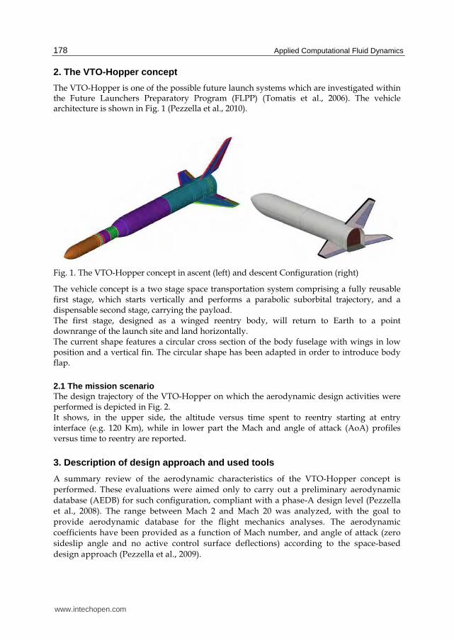
The VTO-Hopper is one of the possible future launch systems which are investigated within the Future Launchers Preparatory Program (FLPP) (Tomatis et al., 2006). The vehicle architecture is shown in Fig. 1 (Pezzella et al., 2010).
Fig. 1. The VTO-Hopper concept in ascent (left) and descent Configuration (right)
The vehicle concept is a two stage space transportation system comprising a fully reusable first stage, which starts vertically and performs a parabolic suborbital trajectory, and a dispensable second stage, carrying the payload. The first stage, designed as a winged reentry body, will return to Earth to a point downrange of the launch site and land horizontally. The current shape features a circular cross section of the body fuselage with wings in low position and a vertical fin. The circular shape has been adapted in order to introduce body flap.
2.1 The mission scenario The design trajectory of the VTO-Hopper on which the aerodynamic design activities were performed is depicted in Fig. 2. It shows, in the upper side, the altitude versus time spent to reentry starting at entry interface (e.g. 120 Km), while in lower part the Mach and angle of attack (AoA) profiles versus time to reentry are reported.
3. Description of design approach and used tools
A summary review of the aerodynamic characteristics of the VTO-Hopper concept is
performed. These evaluations were aimed only to carry out a preliminary aerodynamic
database (AEDB) for such configuration, compliant with a phase-A design level (Pezzella
et al., 2008). The range between Mach 2 and Mach 20 was analyzed, with the goal to
provide aerodynamic database for the flight mechanics analyses. The aerodynamic
coefficients have been provided as a function of Mach number, and angle of attack (zero
sideslip angle and no active control surface deflections) according to the space-based
design approach (Pezzella et al., 2009).
www.intechopen.com

Aerodynamic Design of the Vertical Takeoff Hopper Concept of Future Launchers Preparatory Programme
179
This approach dictates the generation of a complete data set as function of a number of independent parameters (i.e. M, Re, ┙, ). Then, by using engineering based design, one can rapidly develop aerodynamic database as a function of the freestream parameters in a matter of hour (Bertin, 2004). In the present analysis only continuum regime (supersonic and hypersonic speed ranges) with the air modeled as perfect gas has been studied. It is worth to underline, however, that at high altitudes the rarefaction and real gas effects should be taken into account when the vehicle is flying at high Mach number, being the AEDB strongly affected by both these aspects (Bertin, 2004). Therefore, for the prosecution of vehicle design (i.e. phase B and C) more reliable design methodologies are mandatory. In the following paragraphs the tools used for the analysis are described.
0
20
40
60
80
100
120
140
0 200 400 600 800 1000 1200
Time to reentry (s)
Alt
itu
de
(km
)
0
2
4
6
8
10
12
14
16
18
20
0 200 400 600 800 1000 1200
Time to reentry (s)
Mac
h N
o (
-)
0
10
20
30
40
50
60A
oA
(d
eg)
Mach No.
AoA
\
Fig. 2. The VTO-Hopper design trajectory in Altitude-time map (up) and Mach no/AoA vs time to reentry (down)
www.intechopen.com

Applied Computational Fluid Dynamics
180
3.1 Aerodynamic analysis tools The VTO-Hopper has a number of extreme loading flight conditions for which analyses are required. It must return from orbit, fly trimmed throughout hypersonic and supersonic regimes until landing is gained, and withstand severe aeroheating. An accurate aerodynamic analysis of all these flight conditions is very complex and time consuming, and is not compatible with a Phase A design study, in which fast predicting methods are mandatory (Pezzella, 2011). Therefore, the evaluations of the vehicle AEDB and of its reentry aerothermal environment were mainly performed by means of engineering tools, while a limited number of more advanced CFD computations were performed in order to verify the attained accuracy and to focus on some critical design aspects not predictable with simplified tools. Engineering based aerodynamic and aerothermodynamic analyses were extensively performed by using a 3D Panel Methods code developed by CIRA (SIM–Surface Impact Method) in the frame of its research activities on preliminary design of reentry vehicles (Pezzella, 2011). This tool at high supersonic and hypersonic speeds is able to accomplish the aerodynamic and aerothermodynamic analyses of a complex reentry vehicle configuration by using simplified approaches as local surface inclination methods and approximate boundary-layer methods, respectively. Surface Impact Methods (SIM), typical of hypersonics, are: Newtonian, Modified Newtonian, Tangent cone and Tangent Wedge theories (Bertin, 2004). In Fig. 3 is shown a typical mesh surface of VTO-Hopper that has been used for the engineering level computations (Pezzella, 2011). On the other hand the numerical code used to carry out the CFD analyses of the VTO vehicle concept is the CIRA code H3NS (Pezzella et al., 2009). It solves the flowfield governing equations, including chemical and vibrational non-equilibrium, with a finite volume approach; a flux difference splitting upwind scheme is used for the convective terms, with a 2nd order ENO-like reconstruction of cell interface values. The viscous fluxes are calculated by central differencing, i.e. computing the gradients of flow variables at cell interfaces by means of Gauss theorem. Time integration is performed by employing an Euler Forward scheme coupled with a point implicit treatment of the species and vibration energies source terms. Also a parallel version of the code is currently available. Several boundary conditions are available for the viscous computations, including different catalycity models and the possibility to assign at the wall a fixed temperature or a radiative equilibrium condition (Pezzella et al., 2009).
X Y
Z
Fig. 3. Example of surface mesh used for engineering analysis
www.intechopen.com

Aerodynamic Design of the Vertical Takeoff Hopper Concept of Future Launchers Preparatory Programme
181
CFD computations have been carried out on a multiblock structured grid similar to that shown in Fig. 4 that is generated with the commercial tool ICEM-CFD. The grid used for Euler calculations has consisted of 62 blocks for an overall number of 829000 cells (half body).
Fig. 4. Example of multiblock CFD domain. Mesh on symmetry plane and vehicle surface (left). Mesh on vehicle surface (right)
The grid is tailored for the freestream conditions of the trajectory check points, that are summarized in Table 1. The distribution of surface grid points was dictated by the level of resolution desired in various areas of vehicle such as stagnation region and base fillet, according to the computational scopes. Grid refinement in strong gradient regions of flowfield was made through a solution adaptive approach.
4. Aerodynamic analysis and features of the VTO-Hopper vehicle in ascent and descent configuration
The VTO Hopper launcher consists of a rather conventional slender missile-like vehicle with a small delta planform wing (37.2° leading edge sweep) at very rear position and a central vertical stabilizer, as basic shape. The concept shows a circular cross section with a loft fillet on the belly side to accommodate the wing (blended wing body interface). The Wing geometry data are: root/tip chord: 11.70 m / 4.914 m; half span b/2: 11.63 m; wing leading / trailing edge angle: 37.23° / 10°; apex longitudinal position (from the base of the fuselage): 11.70 m; angle of incidence (setting) of the wing: 3°; dihedral: 3°. With these data the wing surface is equal to 193.23 m2. The VTO-Hopper is characterized by a clean aerodynamic configuration, (i.e. controls in neutral position), that is depicted in Fig. 5 for ascent and descent flight.
www.intechopen.com

Applied Computational Fluid Dynamics
182
Fig. 5. Vehicle clean aerodynamic configuration for ascent (up) and descent flight (down)
The aerodynamic controls comprise rudders on the vertical tail, elevons and ailerons on the wings, and a body flap underneath the main engines in order to provide maneuverability and longitudinal stability during atmospheric descent. At hypersonic speeds a surface behind the vehicle centre of gravity (CoG) balances the nose up pitching moment typical of such kind of vehicle configuration at hypersonic speeds (Bertin, 2004). Normalizing the vehicle overall dimensions by fuselage length (Lref=58.8 m), the VTO-Hopper is characterized by the following normalized reference data:
B’ (wing span)=0.54;
S’ (reference surface)=0.056;
X’MRP=0.69; Y’MRP=0; Z’MRP=0; In the following, the aerodynamic analysis is shown in term of lift (CL), drag (CD) and pitching moment (CMy) coefficients which are calculated according to Eq. 1 and Eq. 2, respectively.
D,LiSv
2
1F
C
ref2
ii
(1)
YjSLv
2
1
MC
refref2
j
jM
(2)
4.1 The VTO-Hopper aerodynamic for ascent flight The aerodynamic performance of VTO Hopper in ascent flight has been carried out starting from the results summarized in (Guédron et al., 2003) for the French concept RFS. The geometry of RFS launcher configuration with booster, expendable upper stage and fairing is shown in Fig. 6.
www.intechopen.com

Aerodynamic Design of the Vertical Takeoff Hopper Concept of Future Launchers Preparatory Programme
183
Fig. 6. RFS Configuration. Dimensions in [m] (Guédron et al., 2003)
As one can see this vehicle concept is characterized by an aerodynamic configuration very close to the VTO one, except for canard flight control surfaces mounted in front of launcher. Therefore, the preliminary ascent AEDB of the VTO-Hopper has been built by properly scaling the RFS’s AEDB on the base of VTO aerodynamic configuration features. For the RFS launcher configuration the aerodynamic coefficients are summarized in Fig. 7 (Guédron et al., 2003).
Fig. 7. Aerodynamic coefficients for ascent flight of RFS launcher (Guédron et al., 2003)
www.intechopen.com
Applied Computational Fluid Dynamics
184
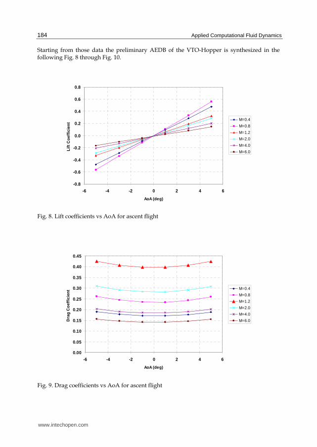
Starting from those data the preliminary AEDB of the VTO-Hopper is synthesized in the following Fig. 8 through Fig. 10.
-0.8
-0.6
-0.4
-0.2
0.0
0.2
0.4
0.6
0.8
-6 -4 -2 0 2 4 6
AoA (deg)
Lif
t C
oef
fici
ent
M=0.4
M=0.8
M=1.2
M=2.0
M=4.0
M=6.0
Fig. 8. Lift coefficients vs AoA for ascent flight
0.00
0.05
0.10
0.15
0.20
0.25
0.30
0.35
0.40
0.45
-6 -4 -2 0 2 4 6
AoA (deg)
Dra
g C
oef
fici
ent M=0.4
M=0.8
M=1.2
M=2.0
M=4.0
M=6.0
Fig. 9. Drag coefficients vs AoA for ascent flight
www.intechopen.com

Aerodynamic Design of the Vertical Takeoff Hopper Concept of Future Launchers Preparatory Programme
185
-0.08
-0.06
-0.04
-0.02
0.00
0.02
0.04
0.06
0.08
-6 -4 -2 0 2 4 6
AoA (deg)
Pit
chin
g m
om
ent
Co
effi
cien
t
M=0.4
M=0.8
M=4.0
M=6.0
Fig. 10. Pitching moment coefficients vs AoA for ascent flight
4.2 The VTO-Hopper aerodynamic for descent flight in clean configuration The re-entry scenario of the VTO-Hopper launcher is summarized in the following Fig. 11
where the flight profile refers to the altitude-velocity map. Moreover, the Mach and
Reynolds numbers grid is also reported in order to characterize the aerodynamic flight
scenario of the booster.
0 1000 2000 3000 4000 5000 6000 70000
2
4
6
8
10
12x 10
4
Velocity [m/s]
Alti
tud
e [m
]
Fig. 11. The VTO-Hopper re-entry trajectory in the altitude-velocity map
www.intechopen.com

Applied Computational Fluid Dynamics
186
Mach number ranges from 2 to 20 while five Reynolds numbers (i.e. [1, 3, 8, 20, 70]x106) with
respect to Lref are displayed. It must be noted that the ranges of Mach and Reynolds numbers
were chosen in such a way to cover a wide part of the reentry flight, especially the most
critical one from the aeroheating point of view (i.e. M=13.4) (Pezzella et al., 2009).
For the VTO-Hopper booster, the following reference parameters have been chosen in order to make aerodynamic forces and moments non-dimensional coefficients (see Fig. 12):
Lref =58.8 [m] (Fuselage length – longitudinal reference length);
Sref =193.23 [m2] (wing wetted area – black in Fig. 12 –)
Pole coordinates are (0,0,0) [m] (e.g., vehicle nose);
Lre
XC
Fig. 12. The VTO-Hopper booster reference parameters
Based on reentry flight scenario summarized in Fig. 11 the aerodynamic data set was
generated for the following ranges:
2 < M < 20 [2, 3, 5, 7, 10, 15, 20];
0° < ┙ < 50° [0, 5, 10, 15, 20, 25, 30, 35, 40, 45, 50];
106 < Re < 70 x 106 [1, 3, 8, 20, 70] x 106;
┚ =0° Neither lateral directional analysis nor wing and body flap effects have been taken into account in this report.
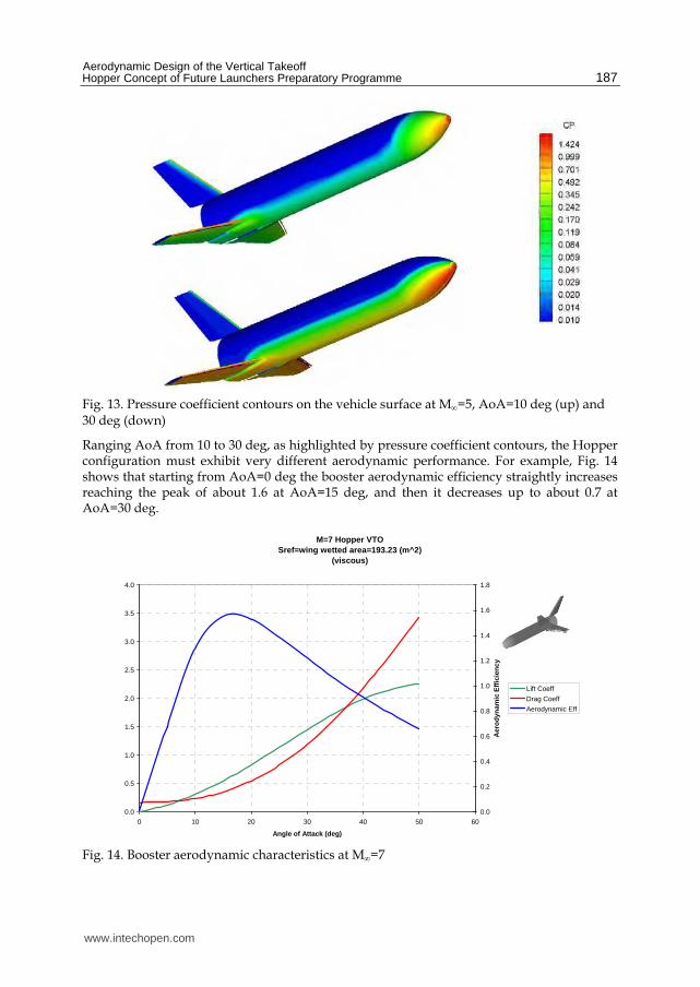
As an example, results for M=5 are summarized in Fig. 13, where the static pressure distribution over the wetted vehicle surface for two AoAs (i.e. 10 and 30 deg) is reported.
www.intechopen.com
Aerodynamic Design of the Vertical Takeoff Hopper Concept of Future Launchers Preparatory Programme
187
Fig. 13. Pressure coefficient contours on the vehicle surface at M=5, AoA=10 deg (up) and 30 deg (down)
Ranging AoA from 10 to 30 deg, as highlighted by pressure coefficient contours, the Hopper configuration must exhibit very different aerodynamic performance. For example, Fig. 14 shows that starting from AoA=0 deg the booster aerodynamic efficiency straightly increases reaching the peak of about 1.6 at AoA=15 deg, and then it decreases up to about 0.7 at AoA=30 deg.
M=7 Hopper VTOSref=wing wetted area=193.23 (m^2)
(viscous)
0.0
0.5
1.0
1.5
2.0
2.5
3.0
3.5
4.0
0 10 20 30 40 50 60
Angle of Attack (deg)
0.0
0.2
0.4
0.6
0.8
1.0
1.2
1.4
1.6
1.8
Aer
od
ynam
ic E
ffic
ien
cy
Lift Coeff
Drag Coeff
Aerodynamic Eff
Fig. 14. Booster aerodynamic characteristics at M=7
www.intechopen.com
Applied Computational Fluid Dynamics
188
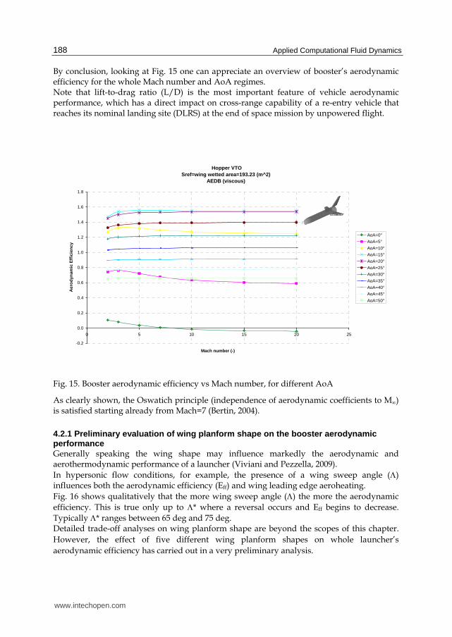
By conclusion, looking at Fig. 15 one can appreciate an overview of booster’s aerodynamic efficiency for the whole Mach number and AoA regimes. Note that lift-to-drag ratio (L/D) is the most important feature of vehicle aerodynamic performance, which has a direct impact on cross-range capability of a re-entry vehicle that reaches its nominal landing site (DLRS) at the end of space mission by unpowered flight.
Hopper VTO
Sref=wing wetted area=193.23 (m^2)AEDB (viscous)
-0.2
0.0
0.2
0.4
0.6
0.8
1.0
1.2
1.4
1.6
1.8
0 5 10 15 20 25
Mach number (-)
Aer
od
ynam
ic E
ffic
ien
cy
AoA=0°
AoA=5°
AoA=10°
AoA=15°
AoA=20°
AoA=25°
AoA=30°
AoA=35°
AoA=40°
AoA=45°
AoA=50°
Fig. 15. Booster aerodynamic efficiency vs Mach number, for different AoA
As clearly shown, the Oswatich principle (independence of aerodynamic coefficients to M)
is satisfied starting already from Mach=7 (Bertin, 2004).
4.2.1 Preliminary evaluation of wing planform shape on the booster aerodynamic performance Generally speaking the wing shape may influence markedly the aerodynamic and aerothermodynamic performance of a launcher (Viviani and Pezzella, 2009).
In hypersonic flow conditions, for example, the presence of a wing sweep angle () influences both the aerodynamic efficiency (Eff) and wing leading edge aeroheating.
Fig. 16 shows qualitatively that the more wing sweep angle () the more the aerodynamic
efficiency. This is true only up to * where a reversal occurs and Eff begins to decrease.
Typically * ranges between 65 deg and 75 deg. Detailed trade-off analyses on wing planform shape are beyond the scopes of this chapter.
However, the effect of five different wing planform shapes on whole launcher’s
aerodynamic efficiency has carried out in a very preliminary analysis.
www.intechopen.com

Aerodynamic Design of the Vertical Takeoff Hopper Concept of Future Launchers Preparatory Programme
189
A simplified approach has been used to build the wing. Each of them has been derived by
scaling up the baseline geometry, in x and y directions, by different factors.
An overview of these wing planforms are shown in Fig. 17. The first wing, identified as step
#1, has been obtained scaling up the baseline one in x-direction by 1.5, taking constant y.
The second one (e.g., step #2) is characterized by a x scaling of a factor of two.
Eff
*
Fig. 16. Qualitatively behavior of Eff vs wing swept.
The wing number three (step #3) differs from the baseline one for a y scaling by a factor of
1.3. The step #4 identifies a wing obtained by x and y scaling up the baseline by a factor of
1.5 and 1.3, respectively.
Finally, the wing step #5 is obtained by x and y scaling the baseline wing by a factor of 2 and
1.3, respectively.
Fig. 18 shows the comparison between the baseline configuration on the left side of the
booster and the modified wing (e.g., step #i) on the right side. Therefore, one can appreciate
at same time the wing differences.
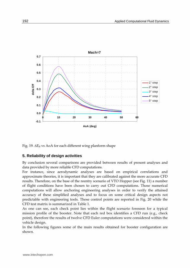
The effect of each wing shape is summarized in Fig. 19 where is shown the Eff (e.g., aerodynamic efficiency with respect the baseline at the same AoA) versus AoA at M∞=7. Note that this Mach number was chosen as representative of whole hypersonic regime on the base of Oswatich principle. As one can see, a strong effect can be appreciated only around AoA=10 deg. Therefore, if the vehicle re-enters flying at an AoA higher than 20 deg no matter is wing planform shape on aerodynamic performance for a configuration as such that of VTO Hopper.
www.intechopen.com

Applied Computational Fluid Dynamics
190
Baseline Step #1: X scale=1.5
Step #2: X scale =2
Step #3 Y scale=1.3
Step #4 X scale=1.5 Y scale=1.3
Step #5 X scale=2
Y scale=1.3
X
Y
Fig. 17. The VTO-Hopper booster with different wing planform shapes
www.intechopen.com

Aerodynamic Design of the Vertical Takeoff Hopper Concept of Future Launchers Preparatory Programme
191
Baseline – Step #3 Baseline – Step #2
Baseline – Step #1
Baseline – Step #4 Baseline – Step #5
Fig. 18. The VTO-Hopper booster with base line wing (left side) and different wing planform shapes (right side)
www.intechopen.com
Applied Computational Fluid Dynamics
192
Mach=7
-0.1
0.0
0.1
0.2
0.3
0.4
0.5
0.6
0.7
0 10 20 30 40 50 60
AoA (deg)
del
ta E
ff
1° step
2° step
3° step
4° step
5° step
Fig. 19. Eff vs AoA for each different wing planform shape
5. Reliability of design activities
By conclusion several comparisons are provided between results of present analyses and
data provided by more reliable CFD computations.
For instance, since aerodynamic analyses are based on empirical correlations and
approximate theories, it is important that they are calibrated against the more accurate CFD
results. Therefore, on the base of the reentry scenario of VTO Hopper (see Fig. 11) a number
of flight conditions have been chosen to carry out CFD computations. Those numerical
computations will allow anchoring engineering analyses in order to verify the attained
accuracy of these simplified analyses and to focus on some critical design aspects not
predictable with engineering tools. Those control points are reported in Fig. 20 while the
CFD test matrix is summarized in Table 1.
As one can see, each check point lies within the flight scenario foreseen for a typical
mission profile of the booster. Note that each red box identifies a CFD run (e.g., check
point), therefore the results of twelve CFD Euler computations were considered within the
vehicle design.
In the following figures some of the main results obtained for booster configuration are
shown.
www.intechopen.com

Aerodynamic Design of the Vertical Takeoff Hopper Concept of Future Launchers Preparatory Programme
193
For example, Fig. 21 shows the normalized temperature contours field both on the vehicle
symmetry plane and booster outer surface when the vehicle is flying at M=5 and
AoA=10 deg.
VTO-SOH-reentry
0
2
4
6
8
10
12
14
16
18
20
0 200 400 600 800 1000 1200
Time to reentry (s)
Mac
h N
o (
-)
0
10
20
30
40
50
60
Ao
A (
deg
)
Mach No.
AoA
CFD Control Point
M=10M=5
M=16
M=13.4
Fig. 20. The VTO-Hopper booster re-entry scenario with control points for CFD analyses
AoA [deg]
Mach [-]
5 10 13.4 16 0 10 20 30 40 50
Table 1. The CFD Test Matrix
Looking at contour field on the vehicle symmetry plane one can appreciate the strong bow shock that occurs ahead of vehicle during descent. This shock surface envelopes the vehicle and may impinge on wing leading edge (e.g., shock-shock interaction – SSI) thus increasing locally the heat flux (overheating) that the vehicle thermal shield has to withstand, as shown in Fig. 22 where the Mach number contour field in the cross plane where bow shock impinges over the wing for M∞=10, AoA=20 deg is displayed. Therefore, analyses of SSI with overloads (pressure and heat flux) at impingement are mandatory for a reliable vehicle design (Viviani and Pezzella, 2009).
www.intechopen.com

Applied Computational Fluid Dynamics
194
Fig. 21. Normalized temperature contours on symmetry plane and vehicle surface at M∞=5, AoA=10 deg. Euler computation.
Fig. 22. Mach number contours in the cross plane where bow shock impinges over the wing (SSI) for M∞=10 and AoA=20 deg. Euler CFD computation
Further flowfield features can be recognized in Fig. 23, where the normalized pressure contour field is shown for M∞=5 and AoA=20 deg.
www.intechopen.com

Aerodynamic Design of the Vertical Takeoff Hopper Concept of Future Launchers Preparatory Programme
195
Fig. 23. Normalized pressure contours on vehicle surface at M∞=5, AoA=20 deg. Euler computation
For what concerns the reliability of aerodynamic coefficient from Fig. 24 to Fig. 29 it can be clearly noted the good agreement between the engineering-based aerodynamics and the CFD data.
Hopper-VTO Sref=wing wetted area=193.23 (m^2)
AEDB (inviscid)Mach=10
-0.5
0.0
0.5
1.0
1.5
2.0
2.5
0 10 20 30 40 50 60
Angle of Attack (deg)
Lif
t C
oef
fici
ent
CIRA engineering-SIM
CFD-Euler
Fig. 24. Lift coefficient vs AoA. Comparison between SIM and CFD Euler at M=10.
www.intechopen.com

Applied Computational Fluid Dynamics
196
Hopper-VTO Sref=wing wetted area=193.23 (m^2)
AEDB (inviscid)Mach=10
0.0
0.5
1.0
1.5
2.0
2.5
3.0
3.5
0 10 20 30 40 50 60
Angle of Attack (deg)
Dra
g C
oef
fici
ent
CIRA engineering-SIM
CFD-Euler
Fig. 25. Drag coefficient vs AoA. Comparison between SIM and CFD Euler at M=10.
Hopper-VTO AEDB (viscous)Sref=wing wetted area=193.23 (m^2); Lref=fuselage length=58.807 (m);
pole @ vehicle nose Mach=10
-3.0
-2.5
-2.0
-1.5
-1.0
-0.5
0.0
0.5
0 10 20 30 40 50 60
Angle of Attack (deg)
Pit
chin
g m
om
ent
coef
fici
ent
CIRA engineering-SIM
CFD-Euler
Fig. 26. Pitching moment coefficient vs AoA. Comparison between SIM and CFD Euler at
M=10.
www.intechopen.com

Aerodynamic Design of the Vertical Takeoff Hopper Concept of Future Launchers Preparatory Programme
197
Hopper-VTO Sref=wing wetted area=193.23 (m^2)
AEDB (inviscid)Mach=16
-0.5
0.0
0.5
1.0
1.5
2.0
2.5
3.0
0 10 20 30 40 50 60
Angle of Attack (deg)
Lif
t C
oef
fici
ent
CIRA engineering-SIM
CFD-Euler
Fig. 27. Lift coefficient vs AoA. Comparison between SIM and CFD Euler at M=16 (error bar for 10%).
Hopper-VTO
Sref=wing wetted area=193.23 (m^2)AEDB (inviscid)
Mach=16
0.0
0.5
1.0
1.5
2.0
2.5
3.0
3.5
4.0
0 10 20 30 40 50 60
Angle of Attack (deg)
Dra
g C
oef
fici
ent
CIRA engineering-SIM
CFD-Euler
Fig. 28. Drag coefficient vs AoA. Comparison between SIM and CFD Euler at M=16 (error bar for 10%).
www.intechopen.com

Applied Computational Fluid Dynamics
198
Hopper-VTO AEDB (viscous)Sref=wing wetted area=193.23 (m^2); Lref=fuselage length=58.807 (m);
pole @ vehicle nose Mach=16
-3.5
-3.0
-2.5
-2.0
-1.5
-1.0
-0.5
0.0
0.5
0 10 20 30 40 50 60
Angle of Attack (deg)
Pit
chin
g m
om
ent
coef
fici
ent
CIRA engineering-SIM
CFD-Euler
Fig. 29. Pitching moment coefficient vs AoA. Comparison between SIM and CFD Euler at
M=16 (error bar for 10%).
As clearly evident, results of engineering based approach and CFD computations compare very well at each Mach number and AoA considered. The maximum difference was found at Mach 16 and AoA=50 deg even if it is comprised within an error bar of 10%.
6. Concluding remarks
Preliminary hypersonic aerodynamics dataset for the VTO-Hopper, under development as launcher system concept within the Future Launchers Preparatory Program of European Space Agency, have been carried out in the present chapter. The Hopper configuration is a missile-like re-entry body designed for performing a suborbital, parabolic trajectory with a horizontal landing. A possible re-entry mission profile has been considered as design trajectory with respect to the aerodynamics of the vehicle concept. Hopper aerodynamics review analyses refer to Mach number ranging from 2 to 20 and AoA from 0 to 50 deg, which are conditions covering the whole reentry scenario of the vehicle concept (space-based design approach). It must be underlined, however, that present analysis has not been obtained by means of
accurate and more reliable CFD computations. Therefore, a proper margin should be
adopted in recognizing vehicle aerodynamics.
Overall available results highlight that the difference between eulerian CFD and engineering based design is smaller than 10%, thus confirming that surface impact method (SIM) represent a reasonable preliminary design approach in order to accomplish the aerodynamic characterization of a re-entry vehicle across the hypersonic regime. Note, in conclusion, that in the next phases of VTO-Hopper design, further analyses have to be performed on specific topics in order to increase the reliability of the aerodynamic
www.intechopen.com

Aerodynamic Design of the Vertical Takeoff Hopper Concept of Future Launchers Preparatory Programme
199
database and to reduce the design margins. In particular, the attention has to be focused on real gas and rarefaction effects, as well as shock-shock interactions and laminar-to-turbulent transition. The real gas effects can be important because, during atmospheric re-entry, dissociation and ionization processes take place in the shock layer, which can have an influence on the aerodynamic coefficients. Real gas effects are expected to affect stability and control derivatives of vehicle, in particular its pitching moment, as highlighted by first U.S Space Shuttle reentry (STS-1) where an unexpected higher nose-up pitching moment required a body-flap deflection twice the one predicted by the pre-flight analyses to trim the Orbiter. Moreover, real gas effects cause a shock that lies closer to the vehicle with respect to the position that would characterize a perfect gas case. These effects obviously occur only at higher Mach numbers. Further, regarding to the aerodynamic coefficients, it is well known that at very high altitude, when the Reynolds number decreases and rarefaction effects are present, there is a strong increase of the drag coefficient and a consequent reduction of the maximum efficiency. Another aspect that has to be considered is the interaction of the bow shock with the shock generated by the wing. It is an important phenomenon that has to be investigated because it can have a significant impact on the local pressure and heat flux distribution.
7. References
Bertin, John J., Hypersonic Aerothermodynamics, AIAA Education Series, 2004. Kauffmann, J. Future European Launch Systems in the FLPP Overview and Objectives. 57th
International Astronautical Congress, 2-6 Oct. 2006, Valencia, Spain. IAC-06-D2.4.05.
Guédron, S., Prel, Y., Bonnal, C., Rojo, I., RLV Concepts and Experimental Vehicle System Studies: Current Statuse, 54th International Astronautical Congress, 29 Sept.-3 Oct. 2003, Bremen, Germany, IAC-03-V.6.05.
Pezzella, G., Marini, M., Roncioni, P., Kauffmann, J., Tomatis, C., Preliminary Design of Vertical Takeoff Hopper Concept of Future Launchers Preparatory Program, Journal of Spacecraft and Rockets 2009. ISSN 0022-4650 vol.46 no.4 (788-799) doi: 10.2514/1.39193
Pezzella, G., Marini, M., De Matteis, P., Kauffmann, J., Dapra, A. and Tomatis, C., Aerothermodynamic Analyses of Four Reusable Launchers in the Framework of ESA Future Launchers Preparatory Programme. Aerotecnica Missili & Spazio (The Journal of Aerospace Science, Technologies & Systems). Vol. 89 No. 1 January 2010.
Pezzella, G., Aerodynamics and Aerothermodynamics Analysis of Three Winged Re-Entry Vehicle Concepts. International Journal of Engineering and Allied Sciences (IJEAS), Volume (1): Issue (1). 2011. ISSN 2248-8568.
Pezzella, G., Aerodynamic and Aerothermodynamic Trade-off Analysis of a Small Hypersonic Flying Test Bed. Acta Astronautica. doi:10.1016/j.actaastro.2011.03.004. Volume (69): Issue (3-4). 2011. ISSN (0094-5765): pag.: 209-222.
Pezzella, G., Preliminary Aerodynamic and Aerothermodynamic Assessment of the VTO Hopper Booster. ISRN Mechanical Engineering. Volume 2011, Article ID 215785, 15 pages. doi:10.5402/2011/215785.
Pezzella, G., Marini, M., Roncioni, P., Kauffmann, J., Tomatis, C., Aerodynamic and Aerothermodynamic Evaluation of the VTO Hopper Concept in the Frame of ESA Future Launchers Preparatory Program, 15th AIAA International Space Planes and
www.intechopen.com

Applied Computational Fluid Dynamics
200
Hypersonic Systems and Technologies Conference. Apr. 28-1, 2008. Dayton, Ohio (USA), paper AIAA-2008-2639.
Pezzella, G., Kauffmann, J., Dapra, A., Tomatis, C., An Italian Contribution to the Next Generation Launcher in the Framework of ESA Future Launchers Preparatory Programme, XX AIDAA Congress, Milan, Italy, June 29-July 3, 2009.
Tomatis, C., Bouaziz, L., Franck, T., Kauffmann, J., RLV Candidates for European Future Launchers Preparatory Programme. 57th International Astronautical Congress, 2-6 Oct. 2006, Valencia, Spain. IAC-06-D2.2.07.
Viviani, A., Pezzella, G., Heat Transfer Analysis for a Winged Reentry Flight Test Bed, International Journal of Engineering (IJE), Volume (3): Issue (3). 2009. ISSN: 1985-2312.
www.intechopen.com

Applied Computational Fluid DynamicsEdited by Prof. Hyoung Woo Oh
ISBN 978-953-51-0271-7Hard cover, 344 pagesPublisher InTechPublished online 14, March, 2012Published in print edition March, 2012
InTech EuropeUniversity Campus STeP Ri Slavka Krautzeka 83/A 51000 Rijeka, Croatia Phone: +385 (51) 770 447 Fax: +385 (51) 686 166www.intechopen.com
InTech ChinaUnit 405, Office Block, Hotel Equatorial Shanghai No.65, Yan An Road (West), Shanghai, 200040, China
Phone: +86-21-62489820 Fax: +86-21-62489821
This book is served as a reference text to meet the needs of advanced scientists and research engineers whoseek for their own computational fluid dynamics (CFD) skills to solve a variety of fluid flow problems. KeyFeatures: - Flow Modeling in Sedimentation Tank, - Greenhouse Environment, - Hypersonic Aerodynamics, -Cooling Systems Design, - Photochemical Reaction Engineering, - Atmospheric Reentry Problem, - Fluid-Structure Interaction (FSI), - Atomization, - Hydraulic Component Design, - Air Conditioning System, -Industrial Applications of CFD
How to referenceIn order to correctly reference this scholarly work, feel free to copy and paste the following:
Giuseppe Pezzella (2012). Aerodynamic Design of the Vertical Takeoff Hopper Concept of Future LaunchersPreparatory Programme, Applied Computational Fluid Dynamics, Prof. Hyoung Woo Oh (Ed.), ISBN: 978-953-51-0271-7, InTech, Available from: http://www.intechopen.com/books/applied-computational-fluid-dynamics/fluid-dynamics-analysis-of-a-space-vehicle-entering-the-mars-atmosphere-

© 2012 The Author(s). Licensee IntechOpen. This is an open access articledistributed under the terms of the Creative Commons Attribution 3.0License, which permits unrestricted use, distribution, and reproduction inany medium, provided the original work is properly cited.