Shape-Representation and Shape Similarity. Motivation WHY SHAPE ?

Aerodynamic Design Considerations and Shape
Optimization of Flying Wings in Transonic Flight
M. Zhang1, A. Rizzi1, P. Meng1, R. Nangia2, R. Amiree3 and O. Amoignon3
1Royal Institute of Technology (KTH), 10044 Stockholm, Sweden2Nangia Aero Research Associates, Bristol BS8 1QU, UK
3Swedish Defence Research Agency (FOI), 16490 Stockholm, Sweden
This paper provides a technique that minimize the cruise drag (or maximize L/D) fora blended wing body transport with a number of constraints. The wing shape design isdone by splitting the problem into 2D airfoil design and 3D twist optimization with a frozenplanform. A 45% to 50% reduction of inviscid drag is �nally obtained, with desired pitchingmoment. The results indicate that further improvement can be obtained by modifying theplanform and varying the camber more aggressively.
I. Introduction & Overview
Historically, the ying wing aircraft concept dates as far back as to 1910, when Hugo Junkers believedthe ying wing’s potentially large internal volume and low drag made it capable of carrying a reasonableamount of payload e�ciently over a large distance. In the 30’s and 40’s the ying wing concept was studiedextensively and a series of designs were tried out, with the Horten Ho 229 �ghter being the most famousone (Fig 1). Currently, a Blended Wing Body con�guration is being investigated by NASA and its industrypartners, which incorporates both a ying wing and and the features of conventional transport aircraft (Fig2). The BWB is quiet, strong, inexpensive to build, and because of its economical performance is a promisingcandidate for the future large airliner. Estimates indicate that it is capable of carrying larger payload withbetter fuel e�ciency, for both civilian and military applications, than conventional con�gurations.
Figure 1. Horten Ho 2291 Figure 2. Blended Wing Body2
The BWB aircraft eliminates the tail of the conventional aircraft and blends the fuselage with thewing. Essentially a ying wing, it has been studied extensively by Liebeck et al.17 and many others.The BWB center-body provides lift which improves the aerodynamic performance by reducing the wingloading, compared to the cylindrical fuselage of a conventional aircraft. Moreover, because of its smallerouter wing, the decrease in wetted area relative to a similar sized conventional aircraft translates into anincreased lift-to-drag ratio. For a very large BWB the low wetted-area-to-volume ratio compounds thebene�t.
1 of 17
American Institute of Aeronautics and Astronautics
12th AIAA Aviation Technology, Integration, and Operations (ATIO) Conference and 14th AIAA/ISSM17 - 19 September 2012, Indianapolis, Indiana
AIAA 2012-5402
Copyright © 2012 by Arthur Rizzi. Published by the American Institute of Aeronautics and Astronautics, Inc., with permission.
Dow
nloa
ded
by A
rthu
r R
izzi
on
Oct
ober
9, 2
012
| http
://ar
c.ai
aa.o
rg |
DO
I: 1
0.25
14/6
.201
2-54
02
The paper presents an optimization technique applied to the transonic-wing design of the MOB BWBaircraft studied by Ciampa et al.3
A good deal of the aerodynamic design work has been carried out with Euler-based optimization tech-niques and the results have demonstrated the potential for ‘discovering’ aerodynamically e�cient featuresof ying wings. Using higher-�delity optimization at the conceptual design phase may lead the way to newand innovative shapes that might not have been discovered otherwise. Typical components in the tool-chestused to explore the conceptual design space are: a CFD ow solver, gradient-evaluation algorithm and opti-mizer, and an integrated geometry and mesh manager which provides a exible parametrization linked witha robust and rapid mesh movement algorithm.
We focus on the transonic-cruise design with an Euler solver and gradient-based optimization to determinethe minimum wave-drag and induced-drag design. The baseline con�guration is the zero-twist and zero-camber version of the Ciampa et al.3 geometry. As constraints, the planform and airfoil thickness at eachsection are held to the baseline values. Other constraints are formulated as needed, such as limits on pitchingmoment, etc. The optimization problem then is to �nd the spanwise wing-twist distribution and the camberof each airfoil section. Key considerations include: wave drag, spanwise load distribution, aerofoil sectiondesign, and 3D shaping of the wing for performance improvement.
A. Challenges to Design Highly Swept Flying Wing
Highly swept wings, always accompanied with low aspect ratio or highly taper ratio, will cause the leading-edge suction peaks to stall at at some critical lift coe�cient, and the lift-induced drag increases accordingly.The other challenge is that the outer wing, with increasing sweep angle and decreasing taper ratio, is highlyloaded. It means that the tip is prone to stall �rst, which causes a series of problems. First of all, the aileronswould lose their e�ectiveness. Since the tip stall will cause a local lift loss, the large sweep would shift theaerodynamic center forward and cause a nose-up pitching moment. In this state the ying wing is di�cultto control. If the platform is frozen, the designer is induced to increase the outboard washout to release tiploads.
Our speci�c goal here is to explore the conceptual design space of the BWB to see if equal or superioraerodynamic performance can be achieved compared to a conventional large commercial transport, e.g. theB-777, or A-380. Typically the aspect ratio of the BWB is lower, e.g. around 5, compared to approximately8 to 10 for current civil airliners. Figure 3 shows that the tip-stall tendencies increase with sweepback angle.The MOB BWB studied in this paper and the Boeing blended-wing-body X-48 lie on the central part, andhave planforms more similar in fact to the F-18 than to the B-777.
For low-speed climb-out substantial lift, around CL = 0:6, is required at a limited range of angle ofattack because of passenger deck-angle limitations. The BWB advantage is the promise of lower drag, andthe challenge, as well as the opportunity, occurs at the transonic cruise condition, say around Mcr = 0:8.Interference drag is reduced due to the elimination and reduction of junctions between the wings and thefuselage, resulting in a more streamlined shape for the BWB. The naturally area-ruled shape of the BWBmeans that higher cruise Mach numbers ought to be more easily attainable without changes in the basiccon�guration geometry. In fact, the BWB’s cross-sectional area variation resembles that of the body ofminimum wave drag due to volume (Sears-Haack body) and thus has favorable transonic wave drag.
Certain aerodynamic challenges also exist along side the promises of the BWB to deliver lower drag,especially at transonic cruise. For instance, in order to accommodate passengers, cargo and landing gear,the BWB requires inboard airfoils of unusually large thickness-to-chord ratio, (e.g. 17% thick), which mustalso be maintained along a considerable portion of the chord length, making it a very challenging designproblem to maintain low wave drag. This inboard geometry may also impact unusually strong shock wavebuild-up on the outer wing.
II. Design Procedures and Algorithm
The power of aerodynamic shape optimization (ASO) based on Computational Fluid Dynamics (CFD)is to automatically improve the design of aircraft components. Today, the fastest approach in this typeof optimization is a combination of gradient algorithms for non linear constrained optimization, such asSequential Quadratic Programming, with a solver of the adjoint ow equations. The unstructured owsolver Edge9 solves the compressible Euler equations and its adjoint.10 These must be integrated e�ciently
2 of 17
American Institute of Aeronautics and Astronautics
Dow
nloa
ded
by A
rthu
r R
izzi
on
Oct
ober
9, 2
012
| http
://ar
c.ai
aa.o
rg |
DO
I: 1
0.25
14/6
.201
2-54
02

Figure 3. Planform e�ect on tip stalling leading to pitch-up (re-produced from Whitford,27 Fig. 41
with the geometrical parametrization and mesh adaption by deformation, as explained by Amoignon.12 Theformal optimization problem that will be solved then aims at the reduction of the inviscid drag, i.e. wavedrag due to shocks and lift-induced drag, at one design point de�ned by the Mach number M and angle-of-attack �, or lift coe�cient, including constraints on the lift, pitching moment and geometrical characteristicslike thicknesses and wing planform. Such an optimal design problem takes the form:8>>>>>>>>>>>><>>>>>>>>>>>>:
mina2Rn
CD (w;X) subject to
CL (w;X) � l0 ;
l1 � Cm (w;X) � l2 ;
gj (X�) � 0 ; 1 � j � m;
R (wk;X;M; �) = 0 ;
M (X;X�) = 0 ;
S (X�;a) = 0 ;
(1)
where a is the vector of parameters being optimized, the aerodynamic coe�cients CD, CL and Cm denotethe drag, the lift and pitching moment coe�cients, l0, l1 and l2 are real numbers and gj denotes the jth
geometrical constraint. For application in this paper the design point will be transonic cruise at Mcr = 0:8and CL = 0:3. The discretized ow equations, mesh adaption equation and parametrization, respectively,are described above as systems of equations written in residual form R, M and S in order to have as lightnotations as possible. The vector of mesh coordinates is X, its restriction on the shape being deformeddenoted X�, and the vector of all ow unknowns (density, velocity and pressure) at all nodes in the meshw. The adjoint of the discretized ow equations, the mesh deformation, and the details of the gradientcomputation are presented in detail by Amoignon and Berggren.11
The mesh-deformation - adjoint scheme introduced above guarantees smoothness of objective functionwith parameter variation, and is certainly much to be recommended. The current paper has instead used the
3 of 17
American Institute of Aeronautics and Astronautics
Dow
nloa
ded
by A
rthu
r R
izzi
on
Oct
ober
9, 2
012
| http
://ar
c.ai
aa.o
rg |
DO
I: 1
0.25
14/6
.201
2-54
02

loose coupling of CFD solver with CAD and mesh software, so our focus here will be on the integration of theCAD parametrization in the optimization loop using the surface modeler-mesher sumo7 which constructs themesh on the parametric surface patches by a 3D circumsphere criterion to produce a 3D-Delaunay grid. Onemay then worry about di�erentiability, but that has not created any noticeable problems in the computationsreported.
A. Engineer-in-Loop: Re-meshing Technique
In this paper we choose re-meshing together with a �nite-di�erence approximation of gradients and involvethe engineer very much in the loop. Optimization steps are used as indications to the engineer on whatdirection her design modi�cations should choose. Figure 4 shows the ow chart of solving the optimizationproblem. The geometry is parameterized and sent to CAD and the mesh generator sumo, CFD computationsare carried out on a
Figure 4. Flow chart of the optimization procedure with the engineer in the loop to guide the search
cluster and the results are sent back to the optimizer. The optimizer assesses progress towards a minimum.The iterations will stop once the optimizer estimates that future improvements will be small, e.g. by assessinggradients. As explained below, it is a two-step procedure, and a distinguishing feature of our approach isthat the engineer is very much in the loop to guide the parameter search.
The Matlab c Optimization Toolbox provides a number of algorithms. In this paper an interior-pointalgorithm18 is used. In order to capture the di�erence in geometry when small variations of geometrical pa-rameters are applied, the minimum di�erence change to all the design parameters (to calculate the Jacobian)is restricted to a relatively large number 0:01. To reduce the computation time, the gradient is calculatedby �nite di�erences of the function using parallel computing: all derivatives are computed at once, each oneon its own pc cluster node.
B. sumo-Based Wing Geometry: Parametrization & Re-Meshing
The surface modeler sumo de�nes the wing surface by a given number of airfoils speci�ed along the span ofthe wing (Fig 5).
4 of 17
American Institute of Aeronautics and Astronautics
Dow
nloa
ded
by A
rthu
r R
izzi
on
Oct
ober
9, 2
012
| http
://ar
c.ai
aa.o
rg |
DO
I: 1
0.25
14/6
.201
2-54
02

(a) Creating wing surface with sumo (b) sumo-based geometry parametrization
(c) Symmetric airfoil parametrization by four cubic Beziercurves
(d) Cambered airfoil parametrization by adding the thick-ness distribution to a parameterized camber line (a cubicBezier curve) controlled by four control points
Figure 5. Airfoil-wing parametrization and re-meshing: a two-step procedure.
It stores the cross-sectional information (points) as skeletons for the components e.g., wings, fuselages, na-celles, and pylons. All the surfaces are represented by bi-parametric patches of the form (x; y; z) = S(u; v),where at least the �rst derivatives with respect to the parameters u and v are continuous7 across patchboundaries and the parametrization is such that G1-continuity ensues.. It provides an easy-to-change envi-ronment to modify/re-construct the geometry by specifying the global or/and local leading edge positions,cross-section points, twists, rotations, etc., which are the parameters we control.
sumo together with the TetGen28 automatic tetrahedral mesher can provide a high-quality unstructuredvolume mesh for Euler computation in few seconds.
To proceed step by step with a reduced number of design parameters at each step, the overall optimizationtask is split into sequential processes, 2D airfoil design and 3D twist optimization. which again choice ofthickness distribution and choice of camber, The 2D level is again split into two, with airfoil geometry treatedas a combination of thickness distribution and the added camber e�ect. The overall problem is not exactlyseparable in this way, so there is no guarantee of �nding the overall optimum in this way, but we have foundthe decomposition very instructive for the engineer. Anyway, there is no guarantee of �nding global optima,so we are content to obtain improvements and to understand why the proposed change was bene�cial.
� the thickness distribution is obtained from a parameterized symmetric airfoil, similarly to Venkatara-man.19 Four control points, or seven design variables are used for each section. There are six indepen-dent sections to make the wing, thus 42 design variables to be optimized at this stage;
5 of 17
American Institute of Aeronautics and Astronautics
Dow
nloa
ded
by A
rthu
r R
izzi
on
Oct
ober
9, 2
012
| http
://ar
c.ai
aa.o
rg |
DO
I: 1
0.25
14/6
.201
2-54
02

� the camber line of each section is parameterized by a cubic Bezier curve, with two control points sittingin the nose and the tail and two free for a total of 4 dof per section. The cambered airfoil is obtainedby adding the thickness distribution to the camber line.
The complete wing geometry parametrization is completed by the choice of twist,
� local twist angle is parameterized within the functionality in sumo.
III. Transonic Cruise Design
Many di�erent BWB con�guration studies have been reported in the literature, e.g. the MOB-Projectcon�guration, the European VELA Projects (3 di�erent layouts), the current NASA X-48 con�guration basedon Liebeck’s design, and many others. We have already worked on a derivative of the MOB con�guration,as de�ned by Ciampa et al.3 for the parametrization of its geometry.
The MOB geometry was made available to us by DLR in the CPACS format developed by DLR.6
Translators have been developed so that CPACS �les can be sent to sumo through the wrapping �lters,.31
Note that CPACS supports a wealth of information, such as engine performance data, structural components,etc., of which we use but the exterior geometry. The generality of CPACS enables investigation of eg.aero-elastic design by optimization steps and provides a very general data format for aircraft design, fromconceptual design on.
The reference area used for aerodynamic coe�cients is Sref = 1369m2 (full span model), with referencelength cref = 27:4m, which is the mean aerodynamic chord (MAC).
That BWB geometry has a leading edge sweep angle 64� and low aspect ratio less than 5. This con�g-uration will cause leading-edge suction peaks especially at the tip region. Steady state Euler computationswere made from low speed up to transonic speed showing that the maximum Lift-to-drag ratios is about 15at M1 = 0:65.4 This is not competitive with Lift-to-drag ratios L=D = 21:5 at CL � 0:6. for conventionalaircraft.
The challenge for the BWB, as we see it, is transonic cruise at Mcr = 0:8 where one wants to reachL=D � 22 for a CL � 0:3, i.e. about 136 counts of total drag, CD � 0:0136, i.e., CD = CD0
+CDi� 0:0136.
In addition the design must o�er acceptable pitching moment and wing-bending moment.
(a) (b)
Figure 6. BWB initial model (a) iso-sonic and isoMach contours at cruise condition Mcr = 0:8, CL = 0:3 ; (b)initial platform properties
A. Design Considerations
The initial wing has inviscid drag CDi� 0:0147 which exceeds the goal around 50%. Figure 6(a) shows that
the local Mach is up to 1.9 at the outer wing, accompanied with a strong shock starting to build-up at thecrank. The shock wave is likely to form �rst from the crank along the outer sections. The very high sweepangle at the inboard wing section makes the outer part of the wing more exposed to the trailing vorticity in
6 of 17
American Institute of Aeronautics and Astronautics
Dow
nloa
ded
by A
rthu
r R
izzi
on
Oct
ober
9, 2
012
| http
://ar
c.ai
aa.o
rg |
DO
I: 1
0.25
14/6
.201
2-54
02
the wake of the inboard wing sections. The sudden reduction of the sweep angle on the outer wing sectionincreases the e�ective Mach locally so the shock forms earlier on that part of the wing.
Note that the initial wing is washed-in, namely, the tip wing has more load. The central sections haveextremely large thickness-to-chord ratio around 17% while the outer sections are under 10%.
1. Twist & Camber Design
We now focus on aerodynamic shape optimization of the BWB, and we adopt the baseline geometry asdetermined by Ciampa et al.,3 and use it as the starting point for our minimum drag design.
The classical elliptical aerodynamic loading for a conventional aircraft is not the expected optimum forminimum wave drag.8 Qin et al.8 found a better aerodynamic force distribution to be between the elliptic andtriangular spanwise lift distribution. The optimal spanwise lift distribution for best aerodynamic performanceat both transonic cruise and low speed climb-out may well be a �ne balance of induced drag due to lift andwave drag due to shock wave formation at transonic speeds, perhaps as a combined elliptical/triangulardistribution.
A set of eleven pro�le sections with given thickness and zero camber and twist de�nes the planar BWBwing. sumo closes the wing tip, creates a triangular surface mesh, and generates a volume grid for Eulersimulation using TetGen,28 as described above.
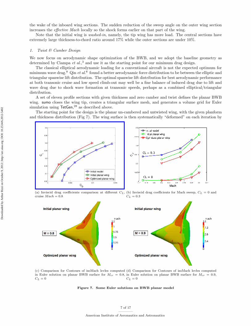
The starting point for the design is the planar un-cambered and untwisted wing, with the given planformand thickness distribution (Fig 7). The wing surface is then systematically \deformed" on each iteration by
(a) Inviscid drag coe�cients comparison at di�erent CL,cruise Mach = 0:8
(b) Inviscid drag coe�cients for Mach sweep, CL = 0 andCL = 0:3
(c) Comparison for Contours of isoMach levles computedin Euler solution on planar BWB surface for Mcr = 0:8,CL = 0
(d) Comparison for Contours of isoMach levles computedin Euler solution on planar BWB surface for Mcr = 0:9,CL = 0
Figure 7. Some Euler solutions on BWB planar model
7 of 17
American Institute of Aeronautics and Astronautics
Dow
nloa
ded
by A
rthu
r R
izzi
on
Oct
ober
9, 2
012
| http
://ar
c.ai
aa.o
rg |
DO
I: 1
0.25
14/6
.201
2-54
02
varying the design parameters controlling the mean camber line and the twist angle, similar to the proceduredescribed in Meng’s thesis30 but there applied to the inverse design problem
2. Constraints
A satisfactory wing design must demonstrate good performance throughout the ight envelope. The designis therefore subject to high and low speed constraints.
Most transport wings follow the time-honoured guidelines (e.g. Kuchemann23) for simple isobar patternat design speed. Further o�-design characteristics have to be acceptable. This implies suitable thicknessdistribution (fuel volume) and local CL and pitch stability constraints. Camber and twist therefore need tobe designed within reasonable planform geometry parameters, without forgetting the aero-elastic behaviouras the design process advances.
Although for minimum drag, spanwise lift distribution is needed, design constraints from structuralconsiderations of e.g. wing bending moment and low speed performance of outer wing may prevent this.Many large aircraft (e.g. A380) use a more triangular spanwise lift loading.
For longitudinal stability, a useful approach for preliminary design is to assume that aircraft is 3-5%MAC stable at low speed and this �xes the CG for high speed. So at high speed Cm � 0. At low speedthat implies need for trim surfaces e.g. elevons to be de ected slightly up. Alternatively, fuel and CGmanagement systems come into play as on most civil aircraft currently.
To specify, the constraints applied practically are as follows:
� thickness taper, which has been applied by Holmes and Hjelte24 at KTH in 1953, is also followed as aconstraint for the thickness distribution of the three-dimensional ying wing at high speed. It has beenshown that a reduction of thickness from the central towards the tips may cause a signi�cant reductionof the velocity increments because of the more three-dimensional nature of the ow. Thickness tapermay be combined with a CL-distribution which increases towards the tip and yet produces fully-sweptisobars. This should bring the vortex drag closer to its minimum value.23
� wash-out, which is always used by wing designers to reduce the lift distribution across the span of thewing. To avoid wing tip stall and aileron ine�ectiveness of swept-wing aircraft (stated in Chapter A),the wing is always designed so that the angle of incidence (local twist) is greater at the wing rootsand decreases across the span, becoming lowest (always negative) at the wing tip. On aircrafts withhighly swept-back wings, the decrease of the local twist angle at the tip would add a nose-up pitchingmoment, which should be considered to be balanced to get it trimmed.
� pitching moment must be su�cient to maintain the stability of the aircraft. A certain stability marginhas to be achieved. In cruise, the aircraft should also be trimmed: so that the lift is not lost to controlsurface de ections. In this condition the trim drag is also small, with L/D the best. At low speed, theneutral point would shift forward. With a too small static margin (SM), it might be unstable at lowspeed and hard to control by the pilot.
� bending moment, is always considered as the �rst step towards aero-structural design. The wing is likelyto bend towards the center of gravity (CG). It might cause aeroelastic problems when the aerodynamicforces couples with the structure’s natural mode of vibration to produce rapid periodic motion, suchas utter or aileron reversal. A practical factor to look into is the local CL (CLL) on the wing. Forthis BWB case the CLL;max should not exceed 0.65, as indicated by Nangia et al.25
Besides, the cabin box in the central body has to �t into the geometry; and the cruise angle of attack(AoA) should be such to keep the cabin oor level.
IV. Results and Discussion
A. First Step Optimized Design { Start with planar wing
We start with the planar wing, all twists and cambers are zero, only the thickness of the airfoils is kept.Figure 9(a) shows the planar BWB geometry created in sumo and used as the start of the optimizationprocedure. The airfoil’s thickness distributions are free to change from the tip to the inboard part close tocentral. Figure 7(c) shows that at cruise condition Mcr = 0:8 a mild shock forms �rst at the outer part of
8 of 17
American Institute of Aeronautics and Astronautics
Dow
nloa
ded
by A
rthu
r R
izzi
on
Oct
ober
9, 2
012
| http
://ar
c.ai
aa.o
rg |
DO
I: 1
0.25
14/6
.201
2-54
02

the wing at zero angle of attack (i.e. zero lift). The ow reaches up to a local Mach number of M = 1:2 inthe red region of Fig. 7(c), and this is not a good sign because if the planar wing already has supersonic ow,adding twist and camber might make it worse, and �nding an acceptable wave drag will be very di�cult.The wing thickness to chord ratio may as well be too high for e�cient M = 0:8 cruise. The optimized planarwing reduces the wave drag coe�cient from 4.8 counts to 3.3 counts, around 31% reduction.
The wave drag at M = 0:8 computed by Edge at zero lift is only a few counts). Thus, the induced dragCDi is comparably large especially at higher CL, due to the appearance of the shock, and it becomes strongerwith increasing Mach and CL (Fig. 7(b)). The optimal thickness distribution for the planar wing serves toreduce the drag at the design point, ie, cruise condition M = 0:8 and CL = 0:3, as well as for higher Machnumbers.
Figure 8 shows that at design cruise condition the shock is signi�cantly weakened. The improved thickness
(a) (b)
Figure 8. BWB planar model: initial planar model v.s. the optimized one, at cruise condition Mcr = 0:8;CL = 0:3 (a) iso-sonic contours; (b) isoMach contours
distribution reduces the shock dramatically especially from the crank down to the tip. This phenomenoncorresponds to Figure 9 the thickness reduction from a bit inboard of the crank (ystation = 17:5m), and ahuge reduction at the crank (ystation = 13m). The station before the crank also has an in uence on the owat the crank and down to the tip, since the high-swept central part makes the outer part more exposed tothe vorticity in its shed wake.
B. Second Step Optimized Design - adding the camber and twisting the wing
The cambers and twists are always coupled, the goal is to further reduce the drag while providing enoughlift. The Angle of Attack (AoA) will be reduced as well. The cruise AoA for civil airliner is supposed to besmall, around 3� is acceptable. The drag is further reduced, while the pitching moment and bending momentare considered at the same time. Due to the con�guration type which has a blended wing body at central,the centre of gravity is a bit aft compared with conventional aircraft, located at 35% MAC. It is calculatedthat the BWB is trimmed (Cm � 0) for its 4th step optimized model, with 45% inviscid CD reduction fromthe initial model. It is obtained by �rst varying camber and then varying twist on the optimized planarwing (2th step optimized design in 11). Figure 10 shows the camber lines and the local twists for this model.The outer wing has negative twist that releases loading at the tip, consistent with modern aircraft designrule that the wing is favourable to have washout. Note that the tip twist is quite large to release loads. Theoptimal design is constrained by the selected constraints, to be expected.
C. Optimized Design Discussion
There are two main steps to iterate to a better design, as stated above. If we look closely at Figure 11, wecan see that we start with the initial wing, or 0th step, then the inviscid drag is reduced �rst by removing allthe twists and cambers, when the con�guration becomes a planar wing, or the 1st optimized design step. Wehave to say the initial wing is a \bad" design, it makes its behaviour worse by adding the cambers and the
9 of 17
American Institute of Aeronautics and Astronautics
Dow
nloa
ded
by A
rthu
r R
izzi
on
Oct
ober
9, 2
012
| http
://ar
c.ai
aa.o
rg |
DO
I: 1
0.25
14/6
.201
2-54
02

(a) (b)
(c) (d)
Figure 9. Thickness distribution design on the planar BWB geometry. (a) The planar BWB geometry withgiven planform and airfoil-section thickness - the starting design model; (b) Comparison of the thicknessdistribution between the initial planar wing and the optimized planar wing; (c) & (d) Comparison of theairfoils between the initial planar wing and the optimized planar wing, at di�erent spanwise stations, red:initial airfoil thickness; blue: optimized airfoil thickness
twists. The re-designed thickness distribution makes the inviscid drag further reduced by 20% from about0:0125 to 0:01. The further reduction is made by varying the twists and the cambers with �xed thicknessdistribution. There are two independent approaches to take. One is to follow the red arrow in Figure 11 by�rst varying the camber (the 3rd optimized design step) and then varying the twist (the 4th optimized designstep), from the optimized planar wing (the 2nd optimized design step), as stated in Section B. We endedup with the 4th step optimized design, with the inviscid drag reduced further by around 19% from around0:01 to 0:0081, and the aircraft trimmed at this stage as well (Fig 13(a)). The other approach is to couplethe camber and twist variation together, following the blue arrow in Figure 11, by varying the camber andtwist at the same time, from the optimized planar wing (the 2nd optimized design step). The drag is furtherreduced to a even lower value by 25% from the 2nd step optimized design, while the trim condition can notbe maintained. This is still quite useful if we further consider the planform into the optimization loop. Toremedy this, in general the neutral point should be shifted a bit forward to obtain good ying qualities,thus the wing part (i.e., the outer wing) can be shifted a bit forward to move the neutral point, while theCG position is almost unchanged. Struber26 did the similar optimization by varying the chord length (�xedsweep angles) in addition to the airfoils shape and local twist, resulting a con�guration with the central partquite aft and outer wing part shifted quite forward. The author also obtained the trim condition (Cm � 0)
10 of 17
American Institute of Aeronautics and Astronautics
Dow
nloa
ded
by A
rthu
r R
izzi
on
Oct
ober
9, 2
012
| http
://ar
c.ai
aa.o
rg |
DO
I: 1
0.25
14/6
.201
2-54
02

(a) (b)
Figure 10. BWB optimized design, (a) camber lines for di�erent ystation from root to tip, normalized by rootchord; (b) local twist angle
Figure 11. BWB optimal design, optimization main steps for CD
if the outer part of wing shifted 3 meters, or 10% MAC forward, and it is called the 5th step of optimizeddesign (Fig. 13(b)).
The initial wing has a local Mach up to 1.9, and forms a strong shock early from the crank down to thetip. The 4th step optimized wing reduces the shock quite a lot, while the 5th step optimized wing almosteliminates the shock at the crank and it only has a mild shock further down to the tip. Note that the 4th
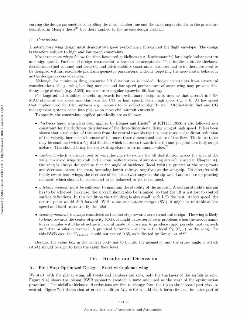
step optimized design almost completely remove the shock at the tip, while pushing it a bit inboard.Now we talk more about why the optimized model has less drag, or, better design. Figure 14(b) and
14(c) show the span loads and local lift coe�cient CLL for each iteration, recalling the Fig. 11. The 0st
step, or the initial MOB, the root is not carrying su�cient loads, while the tip is over loaded. This design isdangerous that the tip is quite likely to stall �rst, as we can see the strong shock existing at the wing tip in6(a). Also the loss of e�ectiveness of moving devices mounted at the tip is also dangerous, especially for the ying wing, whose 3 DOFs moments are all controlled by the quite swept-afterward wing tip devices. Theoptimal MOB has small loads at the tip, while almost the constant loads at the central part until the crank.
11 of 17
American Institute of Aeronautics and Astronautics
Dow
nloa
ded
by A
rthu
r R
izzi
on
Oct
ober
9, 2
012
| http
://ar
c.ai
aa.o
rg |
DO
I: 1
0.25
14/6
.201
2-54
02

(a) (b)
Figure 12. Geometry comparison between the initial MOB (magenta) and the 4th step optimized MOB (green)
(a) BWB optimal design, optimization main steps for CD (b) Comparison of the isoMach contours for the initial wingand the 4th step optimized design
Figure 13. Euler predictions on optimized design of BWB for di�erent steps, for CL = 0:3 at M = 0:8
After the crank, the span-load distribution is more like a triangular. This is consistent with what Qin8 hasstated. The local pressure distribution (Cp) is re�ned to avoid leading edge suction (signi�cant Cp peaks)and strong shocks (pressure jump) while improving the drag. The pressure distribution is overall re�ned,especially near the crank and the outer part, which are quite critical for the drag. Note that the ow atcentral part also in uences the outer region of the wing. The mathematical optimization algorithm is highlycoupled with aerodynamics in this design. A simply reduction of drag in number does not necessarily leadto a good design.
An Reynolds-Averaged Navier-Stoke (RANS) computation on the planar wing has been carried out at thebeginning. The viscous drag is almost 0:0054, so we have the total drag coe�cient at designed lift CL = 0:3:
CD;total = CD;pressure + CD;friction = 0:00807 + 0:0054 = 0:0135 (2)
Thus, we have the L/D at designed cruise point L=D = 22:3 > 21 for the 4th step optimized design, thedesign goal is met.
D. Design Analysis & Remarks
The work is half-done if we only consider \one-point solution". Usually we would like to have an aircraftwith best performance along its ight, not only at one single point. Figure 7(b) already shows that the
12 of 17
American Institute of Aeronautics and Astronautics
Dow
nloa
ded
by A
rthu
r R
izzi
on
Oct
ober
9, 2
012
| http
://ar
c.ai
aa.o
rg |
DO
I: 1
0.25
14/6
.201
2-54
02
(a) iso-sonic contours at cruise condition (b) Span Loads
(c) Local CL (d) Local pressure distribution Cp, quantity demonstration; blackline: initial wing; blue line: 4th step optimized model; red line:5th step optimized model
Figure 14. Comparison between the initial wing and the optimized design in some aspects, computed by EulerEdge, for CL = 0:3 at M = 0:8
design follows a promising trend as Mach number increases. Now we concentrate a bit on ying for variedCL, or AoA. Figure 15 shows two di�erent measuring criteria, drag polar and L/D curve. Both of themindicate that both the 4th and the 5th step optimized designs meet the requirements, not only for the cruisepoint at CL = 0:3.
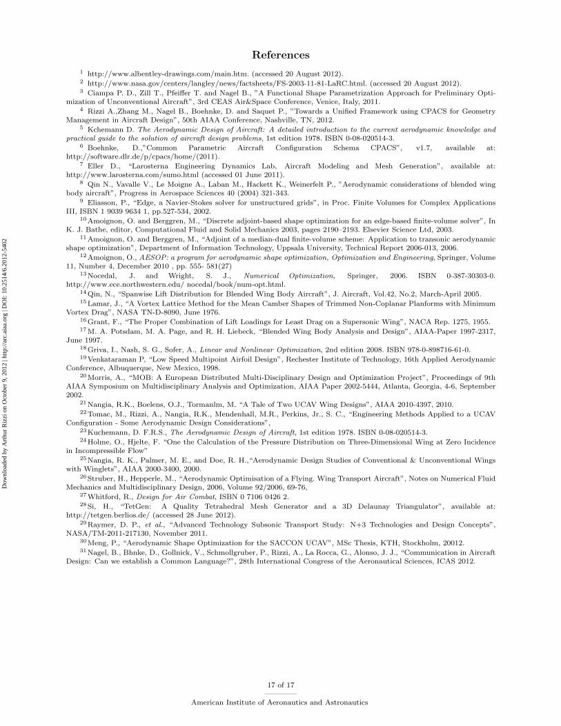
Figure 16 shows that the pressure coe�cient (CP) contour comparisons on the upper surface betweenthe 4th and 5th step optimized designs and the initial one. For both optimized designs the magnitude ofthe negative pressure has been weakened, while the area of the low pressure region is not reduced, resultinga \milder" shock compared with the initial model. Figure 17 and Figure 18 show the comparisons for theairfoils and sectional CP of the three models (initial model: marked by black; the 4th step optimized model:marked by blue; the 5th step optimized model: marked by red) at four spanwise stations. The stations arelabeled in Fig. 16(a).
For the inboard stations (� = 0; 0:15; 0:33), the optimized models are more twisted than the initial one,while the airfoils from 5th step optimized model are a bit more cambered than the 4th step optimized one.The CP is generally re�ned at the central sections. At the crank, where the initial model has a signi�cantpressure jump (shock forms), the 5th step optimized design (red) (Fig. 18(b) for � = 0:33) almost gets rid ofthe sharp pressure jump, thus the shock is reduced quite a lot, if we recall Fig. 16(b) and Fig. 13(b), whereonly a mild shock exists at the crank sitting at around 50% downstream.
13 of 17
American Institute of Aeronautics and Astronautics
Dow
nloa
ded
by A
rthu
r R
izzi
on
Oct
ober
9, 2
012
| http
://ar
c.ai
aa.o
rg |
DO
I: 1
0.25
14/6
.201
2-54
02
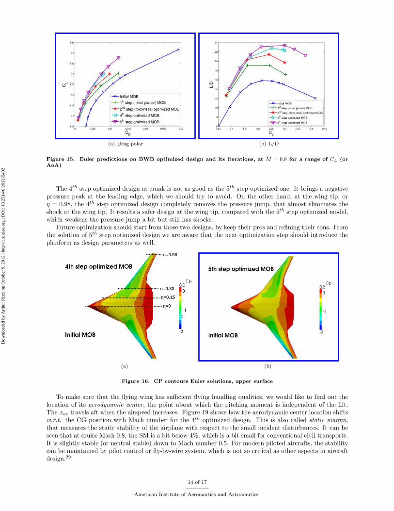
(a) Drag polar (b) L/D
Figure 15. Euler predictions on BWB optimized design and its iterations, at M = 0:8 for a range of CL (orAoA)
The 4th step optimized design at crank is not as good as the 5th step optimized one. It brings a negativepressure peak at the leading edge, which we should try to avoid. On the other hand, at the wing tip, or� = 0:98, the 4th step optimized design completely removes the pressure jump, that almost eliminates theshock at the wing tip. It results a safer design at the wing tip, compared with the 5th step optimized model,which weakens the pressure jump a bit but still has shocks.
Future optimization should start from those two designs, by keep their pros and re�ning their cons. Fromthe solution of 5th step optimized design we are aware that the next optimization step should introduce theplanform as design parameters as well.
(a) (b)
Figure 16. CP contours Euler solutions, upper surface
To make sure that the ying wing has su�cient ying handling qualities, we would like to �nd out thelocation of its aerodynamic center, the point about which the pitching moment is independent of the lift.The xac travels aft when the airspeed increases. Figure 19 shows how the aerodynamic center location shiftsw.r.t. the CG position with Mach number for the 4th optimized design. This is also called static margin,that measures the static stability of the airplane with respect to the small incident disturbances. It can beseen that at cruise Mach 0:8, the SM is a bit below 4%, which is a bit small for conventional civil transports.It is slightly stable (or neutral stable) down to Mach number 0.5. For modern piloted aircrafts, the stabilitycan be maintained by pilot control or y-by-wire system, which is not so critical as other aspects in aircraftdesign.29
14 of 17
American Institute of Aeronautics and Astronautics
Dow
nloa
ded
by A
rthu
r R
izzi
on
Oct
ober
9, 2
012
| http
://ar
c.ai
aa.o
rg |
DO
I: 1
0.25
14/6
.201
2-54
02

(a) (b)
Figure 17. BWB geometry comparison, four spanwise stations, black: initial MOB; blue: the 4th step optimizedMOB; red: the 5th step optimized MOB
(a) (b)
Figure 18. BWB CP comparison, four stations,black: initial MOB; blue: the 4th step optimized MOB; red:the 5th step optimized MOB
E. Thoughts of Future Work
The optimization work can be further proceeded to get a better design. The camber line shape can probablybe improved. For example, re ex camber at the inner sections increases the e�ective leading edge suctionwhere it is relatively lower. Alternatively, allowing the tip section to re ex might be a good way to trim andbalance a clean wing combined with washout at the tips.
The considerations to change the planform would be �rst to change the leading edge position, or shiftthe wing fore (or aft), just as the 5th step optimized design, which shifts the wing part forward resultinga shift of the neutral point while the total lift is maintained. Next we maybe would like to consider to �xthe sweep angle and change the chord length, i.e. we change the taper ratio by stretching or shrinking thechord. Changing the planform would add more design degrees of freedom, it is important to keep it simpleat �rst and make it easy to implement.
V. Conclusions
This paper represents the optimization work for the transonic ying wing: the blended wing body trans-port. The authors describe an e�cient and robust technique to do the geometry parametrization, with Euler
15 of 17
American Institute of Aeronautics and Astronautics
Dow
nloa
ded
by A
rthu
r R
izzi
on
Oct
ober
9, 2
012
| http
://ar
c.ai
aa.o
rg |
DO
I: 1
0.25
14/6
.201
2-54
02

Figure 19. Computed aerodynamic center location xac relative to CG by Euler predictions on BWB 4th stepoptimized design
mesh re-generated every iteration. The work is then straight forward and easy to understand. Engineer mustbe involved in the design loop, to guide the direction of the optimization work. The optimized results showthat it is converged towards the design goal. With the �xed planform, the inviscid drag is reduced by about45% at the designed lift. The aircraft is trimmed at this point, with static margin slightly positive. The wingroot is highly loaded, and the tip load is reduced quite a lot compared with the initial design. However, itintroduces suctions at some span wise stations of the leading edge, which ought to be avoided. An attemptat further improvement is made, by not only parameterizing the wing pro�le shape and local twist, but alsothe planform. It shows that the results can be improved by introducing more design parameters and morestrict constraints.
Acknowledgment
This work was supported by the Swedish National Infrastructure for Computing via the PDC ParallelComputer Center at KTH.
16 of 17
American Institute of Aeronautics and Astronautics
Dow
nloa
ded
by A
rthu
r R
izzi
on
Oct
ober
9, 2
012
| http
://ar
c.ai
aa.o
rg |
DO
I: 1
0.25
14/6
.201
2-54
02
References
1 http://www.albentley-drawings.com/main.htm. (accessed 20 August 2012).2 http://www.nasa.gov/centers/langley/news/factsheets/FS-2003-11-81-LaRC.html. (accessed 20 August 2012).3 Ciampa P. D., Zill T., Pfei�er T. and Nagel B., "A Functional Shape Parametrization Approach for Preliminary Opti-
mization of Unconventional Aircraft", 3rd CEAS Air&Space Conference, Venice, Italy, 2011.4 Rizzi A.,Zhang M., Nagel B., Boehnke, D. and Saquet P., "Towards a Uni�ed Framework using CPACS for Geometry
Management in Aircraft Design", 50th AIAA Conference, Nashville, TN, 2012.5 Kchemann D. The Aerodynamic Design of Aircraft: A detailed introduction to the current aerodynamic knowledge and
practical guide to the solution of aircraft design problems, 1st edition 1978. ISBN 0-08-020514-3.6 Boehnke, D.,"Common Parametric Aircraft Con�guration Schema CPACS", v1.7, available at:
http://software.dlr.de/p/cpacs/home/(2011).7 Eller D., \Larosterna Engineering Dynamics Lab, Aircraft Modeling and Mesh Generation", available at:
http://www.larosterna.com/sumo.html (accessed 01 June 2011).8 Qin N., Vavalle V., Le Moigne A., Laban M., Hackett K., Weinerfelt P., "Aerodynamic considerations of blended wing
body aircraft", Progress in Aerospace Sciences 40 (2004) 321-343.9 Eliasson, P., \Edge, a Navier-Stokes solver for unstructured grids", in Proc. Finite Volumes for Complex Applications
III, ISBN 1 9039 9634 1, pp.527-534, 2002.10Amoignon, O. and Berggren, M., \Discrete adjoint-based shape optimization for an edge-based �nite-volume solver", In
K. J. Bathe, editor, Computational Fluid and Solid Mechanics 2003, pages 2190{2193. Elsevier Science Ltd, 2003.11Amoignon, O. and Berggren, M., \Adjoint of a median-dual �nite-volume scheme: Application to transonic aerodynamic
shape optimization", Department of Information Technology, Uppsala University, Technical Report 2006-013, 2006.12Amoignon, O., AESOP: a program for aerodynamic shape optimization, Optimization and Engineering, Springer, Volume
11, Number 4, December 2010 , pp. 555- 581(27)13Nocedal, J. and Wright, S. J., Numerical Optimization, Springer, 2006. ISBN 0-387-30303-0.
http://www.ece.northwestern.edu/ nocedal/book/num-opt.html.14Qin, N., \Spanwise Lift Distribution for Blended Wing Body Aircraft", J. Aircraft, Vol.42, No.2, March-April 2005.15Lamar, J., \A Vortex Lattice Method for the Mean Camber Shapes of Trimmed Non-Coplanar Planforms with Minimum
Vortex Drag", NASA TN-D-8090, June 1976.16Grant, F., \The Proper Combination of Lift Loadings for Least Drag on a Supersonic Wing", NACA Rep. 1275, 1955.17M. A. Potsdam, M. A. Page, and R. H. Liebeck, \Blended Wing Body Analysis and Design", AIAA-Paper 1997-2317,
June 1997.18Griva, I., Nash, S. G., Sofer, A., Linear and Nonlinear Optimization, 2nd edition 2008. ISBN 978-0-898716-61-0.19Venkataraman P, \Low Speed Multipoint Airfoil Design", Rechester Institute of Technology, 16th Applied Aerodynamic
Conference, Albuquerque, New Mexico, 1998.20Morris, A., \MOB: A European Distributed Multi-Disciplinary Design and Optimization Project", Proceedings of 9th
AIAA Symposium on Multidisciplinary Analysis and Optimization, AIAA Paper 2002-5444, Atlanta, Georgia, 4-6, September2002.
21Nangia, R.K., Boelens, O.J., Tormanlm, M. \A Tale of Two UCAV Wing Designs", AIAA 2010-4397, 2010.22Tomac, M., Rizzi, A., Nangia, R.K., Mendenhall, M.R., Perkins, Jr., S. C., \Engineering Methods Applied to a UCAV
Con�guration - Some Aerodynamic Design Considerations",23Kuchemann, D. F.R.S., The Aerodynamic Design of Aircraft, 1st edition 1978. ISBN 0-08-020514-3.24Holme, O., Hjelte, F. \One the Calculation of the Pressure Distribution on Three-Dimensional Wing at Zero Incidence
in Incompressible Flow"25Nangia, R. K., Palmer, M. E., and Doe, R. H.,\Aerodynamic Design Studies of Conventional & Unconventional Wings
with Winglets", AIAA 2000-3400, 2000.26Struber, H., Hepperle, M., \Aerodynamic Optimisation of a Flying. Wing Transport Aircraft", Notes on Numerical Fluid
Mechanics and Multidisciplinary Design, 2006, Volume 92/2006, 69-76,27Whitford, R., Design for Air Combat, ISBN 0 7106 0426 2.28Si, H., \TetGen: A Quality Tetrahedral Mesh Generator and a 3D Delaunay Triangulator", available at:
http://tetgen.berlios.de/ (accessed 28 June 2012).29Raymer, D. P., et al., \Advanced Technology Subsonic Transport Study: N+3 Technologies and Design Concepts",
NASA/TM-2011-217130, November 2011.30Meng, P., \Aerodynamic Shape Optimization for the SACCON UCAV", MSc Thesis, KTH, Stockholm, 20012.31Nagel, B., Bhnke, D., Gollnick, V., Schmollgruber, P., Rizzi, A., La Rocca, G., Alonso, J. J., \Communication in Aircraft
Design: Can we establish a Common Language?", 28th International Congress of the Aeronautical Sciences, ICAS 2012.
17 of 17
American Institute of Aeronautics and Astronautics
Dow
nloa
ded
by A
rthu
r R
izzi
on
Oct
ober
9, 2
012
| http
://ar
c.ai
aa.o
rg |
DO
I: 1
0.25
14/6
.201
2-54
02