Aerodynamic Control of NASP-Type Vehicles Through Vortex ... · NASP-Type Vehicles Through Vortex...
148
NASA Contractor Report 177626 /N-6_ Aerodynamic Control of NASP-Type Vehicles Through Vortex Manipulation Volume !1 Static Wind Tunnel Tests Carlos J. Su&rez, Brian R. Kramer, Brooke C. Smith, and Gerald N. Malcolm CONTRACT NAS2-13196 September 1993 "_CJ w NASA National Aeronautics and Space Administration (NASA-CR-17762&-Voi-2) AERODYNAMIC CONTROL OF NASP-TYPE VEHICLES THROUGH VOKTEX MANIPULATION- VOLUME 2: STATIC WIND TUNNEL TESTS (Eidetics International) 144 p N94-15677 Unclas G3/02 0190819 https://ntrs.nasa.gov/search.jsp?R=19940011204 2019-02-03T04:24:40+00:00Z
Transcript of Aerodynamic Control of NASP-Type Vehicles Through Vortex ... · NASP-Type Vehicles Through Vortex...

NASA Contractor Report 177626
/N-6_
Aerodynamic Control ofNASP-Type Vehicles ThroughVortex Manipulation
Volume !1
Static Wind Tunnel TestsCarlos J. Su&rez, Brian R. Kramer, Brooke C. Smith, and Gerald N. Malcolm
CONTRACT NAS2-13196
September 1993
"_CJ
w
NASANational Aeronautics andSpace Administration
(NASA-CR-17762&-Voi-2) AERODYNAMICCONTROL OF NASP-TYPE VEHICLESTHROUGH VOKTEX MANIPULATION- VOLUME2: STATIC WIND TUNNEL TESTS(Eidetics International) 144 p
N94-15677
Unclas
G3/02 0190819
https://ntrs.nasa.gov/search.jsp?R=19940011204 2019-02-03T04:24:40+00:00Z


NASA Contractor Report 177626
Aerodynamic Control ofNASP-Type Vehicles ThroughVortex Manipulation
Volume II
Static Wind Tunnel TestsCarlos J. Su&rez, Brian R. Kramer, Brooke C. Smith, and Gerald N. Malcolm
Eidetics International, Inc.3415 Lomita Blvd.
Torrance, CA 90505
tl-
Prepared forAmes Research CenterCONTRACT NAS2-13196
September 1993
National Aeronautics andSpace Administration
Ames Research CenterMoffett Field, California 94035-1000

PAGE_=_=_.._._INTE,_JTIONALLYBLA[_K

TABLE OF CONTENTS
NOMENCLATURE ............................................................................................... v
LIST OF FIGURES ............................................................................................... vi
SUMMARY ............................................................................................................ 1
1.0 INTRODUCTION ...................................................................................... 2
2.0 TECHNICAL OBJECTIVES ..................................................................... 3
3.0 EXPERIMENTAL SETUP ......................................................................... 4
4.0 RESULTS AND DISCUSSION ............................................................. 5
4.1 Force and Moment Measurements ........................................... 5
4.1.1 Baseline Configuration ................................................... 5
4.1.2 Effect of Control Surface Deflections ............................ 7
4.1.3 Effect of Blowing (Aft Blowing, Nozzle A) ..................... 8
4.1.4 Effect of Blowing (Aft Blowing, Nozzles B301N andB30OUT) ............................................................................ 10
4.1.5 Effect of Blowing (Forward Blowing, Nozzles Cand D) ................................................................................. 1 1
4.1.6 Effect of Blowing (Combined Blowing, Nozzles E1and E2) ............................................................................... 12
4.2 Pressure Measurements ............................................................. 12
4.2.1 Baseline Configuration ................................................... 12
4.2.2 Effect of Blowing (Aft Blowing, Nozzle A) ..................... 13
4.2.3 Effect of Blowing (Aft Blowing, Nozzles B301Nand B30OUT) .................................................................... 14
4.2.4 Effect of Blowing (Forward Blowing, Nozzles Cand D) ................................................................................. 1 4
IIIPR'ECEDtNIB PAGE BLANK NOT Ffl.MEb
4.2.5 Effect of Blowing (Combined Blowing, Nozzles E1and E2) ............................................................................... 15
4.3 Time Lag Measurements ............................................................ 15
5.0 CONCLUSIONS ....................................................................................... 16
6.0 ACKNOWLEDGMENTS .......................................................................... 18
7.0 REFERENCES .......................................................................................... 18
FIGURES ............................................................................................................... 20
iv

NOMENCLATURE
ArefbC
L
Ctl
mjqVoo
vjo_,AOA
dedrCNCm(b)Cn(b)Cl(b)Cy(b)CL
ACn(b)ACl(b)ACy(b)Cp
Cnl3C113R/L30
B30
reference wing areawing spanwing chordreference length = total length of the model
momentum coefficient of blowing = rhj Vj / q Arefmass flow rate of the blowing jetfree-stream dynamic pressurefree-stream velocity
average exit velocity of the blowing jet
angle of attack
sideslip angle
roll angle
azimuth angle (from the windward meridian)elevon deflection (+ down)rudder deflection (+ right)normal force coefficientbody axes pitching moment coefficientbody axes yawing moment coefficientbody axes rolling moment coefficientbody axes side force coefficientstability axes lift coefficientbody axes yawing moment incrementbody axes rolling moment incrementbody axes side force incrementpressure coefficientdirectional derivative
lateral derivative
blowing on the right/left side with a reservoir pressure of 30 psi,
which corresponds to a CI_ = 0.00075*
blowing on both sides simultaneously with a reservoir pressure
of 30 psi, which corresponds to a C_ = 0.00075*
L/R/B40, 50 and 60 correspond to CI_ = 0.001, 0.00125 and0.0015, respectively

LIST OF FIGURES
Figure 1 -
Figure 2 -
Figure 3 -
Figure 4 -
Figure 5 -
Figure 6 -
Figure 7 -
Figure 8 -
Figure 9 -
Figure 10 -
Figure 11 -
Figure 12-
Figure 13 -
Figure 14-
Figure 15 -
Figure 16 -
Page
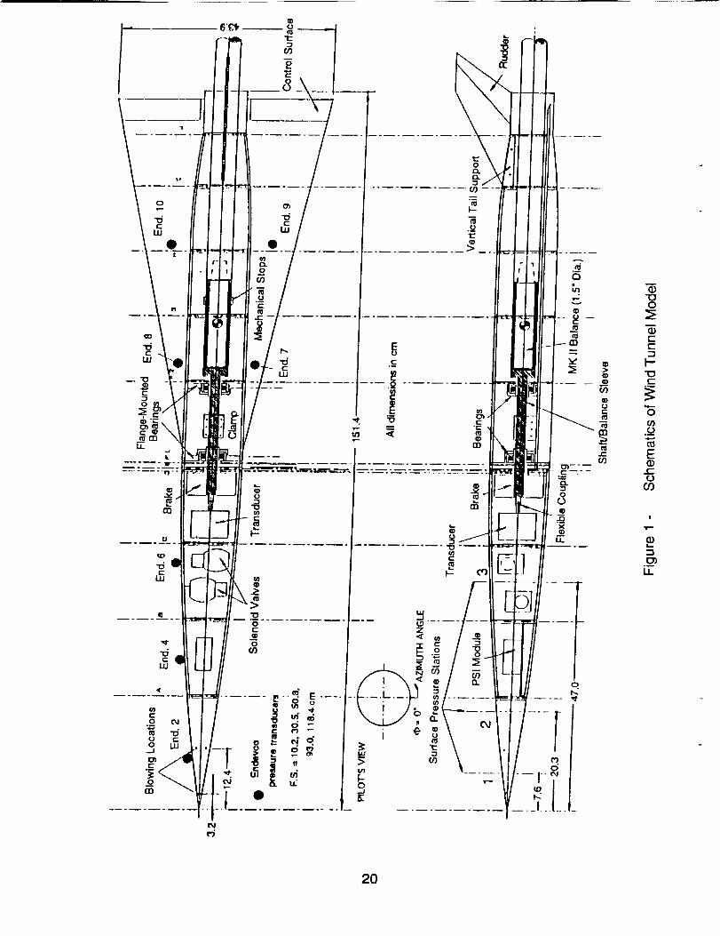
Schematics of Wind Tunnel Model ........................................... 20
Photos of Wind Tunnel Model 21
Schematics of Different Blowing Schemes ............................. 22
Influence of Blowing Ports on Forces and Moments(No Ports vs. Baseline A) ............................................................ 23
Effect of Sideslip Angle on Forces and Moments(Baseline A) ................................................................................... 26
Directional and Lateral Derivatives (Baseline A) ................... 29
Effect of Sideslip Angle on Forces and Moments (No Tail) .. 30
Effect of Elevon Deflection on Forces and Moments ............. 33
Effect of Differential Elevon Deflection (ailerons) onForces and Moments 36
Effect of Rudder Deflection on Forces and Moments ............ 39
Effect of Rudder Deflection on Forces and Moments
(13= -10 °) 42
Effect of Aft Blowing on Forces and Moments
(Nozzle A, Left Side, _ = 0°) ....................................................... 44
Effect of Aft Blowing on Forces and Moments
(Nozzle A, Right Side, 13= 0 °) .................................................... 48
Effect of Aft Blowing on Forces and Moments
(Nozzle A, Both Sides, 13= 0 °) ................................................... 52
Effect of Aft Blowing on Forces and Moments (No Tail)
(Nozzle A, Left Side, 13= 0 °) ....................................................... 55
Effect of Aft Blowing on Forces and Moments (No Tail)
(Nozzle A; Left, Right and Both Sides; [[3= 0°) ........................ 56
vi

Figure 17 -
Figure 18-
Figure 19-
Figure 20 -
Figure 21 -
Figure 22 -
Figure 23 -
Figure 24 -
Figure 25 -
Figure 26 -
Figure 27 -
Figure 28 -
Figure 29 -
Figure 30 -
Figure 31 -
Effect of Aft Blowing on Forces and Moments
(Nozzle A, Left and Right Sides, 13= 5 °) ................................... 58
Effect of Aft Blowing on Forces and Moments
(Nozzle A, Left and Right Sides, 13= -5 °) ................................. 61
Effect of Aft Blowing on Forces and Moments
(Nozzle A, Left and Right Sides, 13=-10 °) ............................... 64
Effect of Aft Blowing on Forces and Moments
(Nozzle B301N, Left and Right Sides, 13= 0 °) .......................... 67
Effect of Aft Blowing on Forces and Moments
(Nozzle B30OUT, Left and Right Sides, 13= 0 °) ...................... 70
Effect of Forward Blowing on Forces and Moments
(Nozzle C; Left, Right and Both Sides, 13= 0 °) ........................ 73
Effect of Forward Blowing on Forces and Moments
(Nozzle C, Left and Right Sides, 13= -10 °) ............................... 77
Effect of Forward Blowing on Forces and Moments
(Nozzle D, Left and Right Sides, 13= 0 °) .................................. 80
Effect of Combined Blowing on Forces and Moments
(Nozzle El, 13= 0 °) .......................... ,._........................................ 83
Effect of Combined Blowing on Forces and Moments
(Nozzle E2, Left Side, 13= 0 °) ..................................................... 84
Forebody Pressure Distribution at Different Angles of
Attack (13= 0 °) ................................................................................ 86
Forebody Pressure Distribution at Different Angles of
Attack (13= 5°) ................................................................................ 87
Forebody Pressure Distribution at Different Angles of
Attack (13=-5 °) .............................................................................. 88
Forebody Pressure Distribution at Different Angles of
Attack (_ =-10 °) ............................................................................ 89
Forebody Pressure Distribution at Different Angles ofAttack (No Tail, 13= 0 °) ................................................................. 90
vii
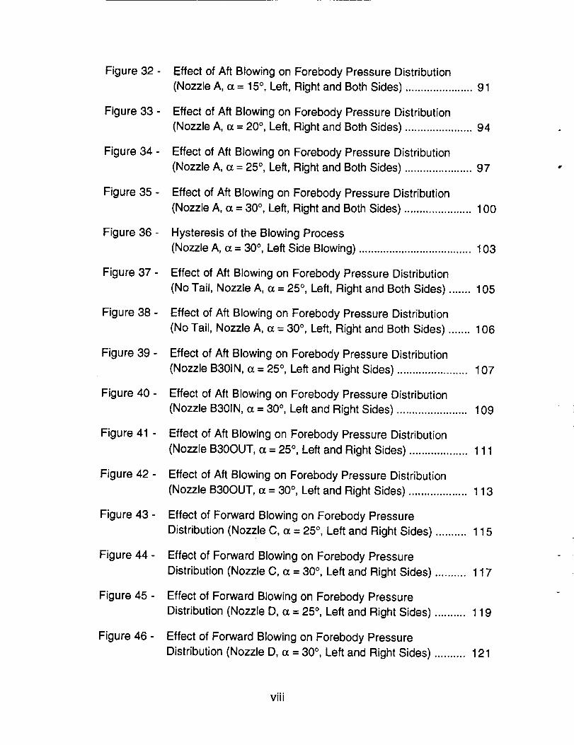
Figure 32 -
Figure 33 -
Figure 34 -
Figure 35 -
Figure 36 -
Figure 37 -
Figure 38 -
Figure 39 -
Figure 40 -
Figure 41 -
Figure 42 -
Figure 43 -
Figure 44 -
Figure 45 -
Figure 46 -
Effect of Aft Blowing on Forebody Pressure Distribution
(Nozzle A, o_= 15 °, Left, Right and Both Sides) ...................... 91
Effect of Aft Blowing on Forebody Pressure Distribution
(Nozzle A, o_= 20 °, Left, Right and Both Sides) ...................... 94
Effect of Aft Blowing on Forebody Pressure Distribution
(Nozzle A, o_= 25 °, Left, Right and Both Sides) ...................... 97
Effect of Aft Blowing on Forebody Pressure Distribution
(Nozzle A, o_= 30 °, Left, Right and Both Sides) ...................... 100
Hysteresis of the Blowing Process
(Nozzle A, c_= 30 °, Left Side Blowing) ............... ........ 103
Effect of Aft Blowing on Forebody Pressure Distribution
(No Tail, Nozzle A, _ = 25 °, Left, Right and Both Sides) ....... 105
Effect of Aft Blowing on Forebody Pressure Distribution
(No Tail, Nozzle A, o_= 30 °, Left, Right and Both Sides) ....... 106
Effect of Aft Blowing on Forebody Pressure Distribution
(Nozzle B301N, cc= 25 °, Left and Right Sides) ....................... 107
Effect of Aft Blowing on Forebody Pressure Distribution
(Nozzle B301N, o_= 30 °, Left and Right Sides) ....................... 109
Effect of Aft Blowing on Forebody Pressure Distribution
(Nozzle B30OUT, o_= 25 °, Left and Right Sides) ................... 111
Effect of Aft Blowing on Forebody Pressure Distribution
(Nozzle B30OUT, cc= 30 °, Left and Right Sides) ................... 113
Effect of Forward Blowing on Forebody Pressure
Distribution (Nozzle C, cz= 25 °, Left and Right Sides) .......... 115
Effect of Forward Blowing on Forebody Pressure
Distribution (Nozzle C, o_= 30 °, Left and Right Sides) .......... 117
Effect of Forward Blowing on Forebody Pressure
Distribution (Nozzle D, o_= 25 °, Left and Right Sides) .......... 119
Effect of Forward Blowing on Forebody Pressure
Distribution (Nozzle D, o_= 30 °, Left and Right Sides) .......... 121
,,o
VIII

Figure 47 -
Figure 48 -
Figure 49 -
Figure 50 -
Figure 51 -
Figure 52 -
Figure 53 -
Figure 54 -
Figure 55 -
Figure 56 -
Effect of Combined Blowing on Forebody Pressure
Distribution (Nozzle El, o_= 25 °) ............................................... 123
Effect of Combined Blowing on Forebody Pressure
Distribution (Nozzle El, (_= 30 °) ............................................... 124
Effect of Combined Blowing on Forebody Pressure
Distribution (Nozzle E2, _ - 25 °, Left Side Blowing) ............. 125
Effect of Combined Blowing on Forebody Pressure
Distribution (Nozzle E2, (z = 30 °) ............................................... 126
Time Response of Forces and Pressures to Blowing Inputs
(Nozzle A, Left Blowing, Cp = 0.0015, o_= 25 °) ...................... 127
Time Response of Forces and Pressures to Blowing Inputs
(Nozzle A, Left Blowing, Cl_ = 0.0015, o_= 30 °) ...................... 128
Time Response of Forces and Pressures to Blowing Inputs
(Nozzle A, Right Blowing, Cp = 0.0015, o_= 30 °) ................... 130
Time Response of Forces and Pressures to Blowing Inputs
(Nozzle A, Simultaneous Blowing, CILt= 0.0015, _ = 30 °) ... 131
Time Response of Forces and Pressures to Blowing Inputs
(Nozzle A, Left and Right Blowing, Cp = 0.0015, (z = 30 °,
13=-10 °) ......................................................................................... 132
Time Response of Forces and Pressures to Blowing Inputs
(Nozzle C, Left and Right Blowing, Cp = 0.0015, e_= 30 °) ... 133
ix


SUMMARY
Forebody Vortex Control (FVC) is an emerging technology that has receivedwidespread and concentrated attention by many researchers for application on fighteraircraft to enhance aerodynamic controllability at high angles of attack. Thistechnology has also been explored in this research program for potential applicationto a NASP-type configuration. Wind tunnel tests, using 6-component force andmoment and surface pressure measurements, have been conducted to evaluate anumber of forebody jet blowing schemes. The configuration tested has a slender,circular cross-section forebody and a 78 ° swept delta wing. Blowing jets wereimplemented on the leeward side of the forebody with small circular tubes tangential tothe surface at various longitudinal locations that could be directed aft, forward, or atangles in between. Jet blowing on each side of the forebody individually and on bothsides simultaneously were evaluated. The effects of blowing are observed primarily inthe yawing and rolling moments and are highly dependent on the jet configuration andthe angle of attack. Effectiveness is also evaluated at sideslip conditions. Results showthat the baseline flow field, without blowing activated, is quite sensitive to the geometrydifferences of the various protruding jets, as well as being sensitive to the blowing,particularly in the angle of attack range where the forebody vortices are naturallyasymmetric. In addition to the static forces, moments and pressures, an assessmentwas made at the time lag of the flow field response to the initiation of blowing. The timeresponse was very short, on the order of the time required for the flow disturbance totravel the distance from the nozzle to the specific airframe location of interest at thefree stream velocity. Overall, results indicate that sizable yawing and rolling momentscan be induced with modest blowing levels. However, direct application of thistechnique on a very slender forebody would require thorough wind tunnel testing tooptimize the jet location and configuration.

AERODYNAMIC CONTROL OF NASP-TYPE VEHICLE-C:THROUGH VORTEX MANIPULATION
VOLUME II: STATIC WIND TUNNEL TEST-_
1.0 INTRODUCTION
One of the most significant and ambitious programs in the aerospace industry inthe near future will be the development and eventual flight test of the National Aero-Space Plane (NASP). A high proportion of the technological research now beingconducted to support the development of a NASP is concentrated in the hypersonicregime. In addition to excellent hypersonic performance, however, high-quality low-speed flight must also be achieved. Conceivably, configurations optimized forhypersonic flight may experience adverse low-speed aerodynamic phenomenadominated by separated and vortex flows, such as wing rock or non-zero yawingmoments at zero sideslip, which could complicate the effort for achieving goodhandling qualities during the takeoff and the approach and landing phases. Usingconventional control effectors such as rudder or aileron to overcome the effects ofthese adverse phenomena and satisfy low-speed flight quality criteria may result in aweight increment over and above that which exists if hypersonic flight quality were theonly concern. Using non-conventional vortex control effectors, on the other hand, maypotentially satisfy low-speed flight quality criteria with a substantially lower weightpenalty. The principal mechanism to accomplish a saving in weight is with fluidamplification, where a small fluidic input, such as surface blowing in the forebodyregion, results in large output control forces and moments to the airframe byinfluencing the vortex flow field.
The powerful forebody vortices are one of the main causes of aircraftinstabilities at high angles of attack. An effective means of suppressing the instabilitiesin this flight regime is, therefore, to directly control these vortices. Recent researchefforts on fighter-type aircraft indicated that some of the most promising methods forForebody Vortex Control (FVC) are movable forebody strakes, rotatable nose-tip andnose-boom devices, and blowing on the forebody surface. The use of symmetricallydeployed forebody strakes has been shown to be effective in forcing naturally-occurring asymmetric vortices at high angles of attack to be symmetric. The largeforebody side forces and resulting yawing moments at zero sideslip are thereforereduced or eliminated. The use of asymmetrically deployed forebody strakes has
been investigated for possible application to controlling the yawing moment 1,2.Rotatable nose-tip devices are also found to be effective in controlling the forebody
flow. These devices are in the forms of a small cylinder attached to the tip3, machinedflats3, elliptic tips 4, and small vortex generators 5. Miniature, rotatable strakes attached
to the nose-boom of an F-16 also influence the forebody vortex flow field, creatingforces and moments that can be used for additional control6. Due in part to theconcern about strakes and mechanical surfaces interfering with forebody radaroperation, various forebody blowing techniques to control the forebody vortexorientations have also been investigated as alternatives to mechanical devices. Two
main forms of blowing have been studied: (1) blowing from a localized jet 2,7,8, and
2

(2) blowing from a tangential slot2,8-12. In either form, blowing was found to be highlyeffective in controlling the vortex orientation.
The Phase I technical results (Ref. 13) show that it is potentially feasible toutilize vortex manipulation with blowing to provide the necessary control forces for aNASP-type configuration, as well as fighter configurations, at low speeds. The massflow requirements for blowing scaled to a full-size NASP based on sub-scaleexperiments appear to be low, well within practical limits of acquiring the requiredmass flow through engine bleed or similar sources. The resulting control moments,based on wind tunnel studies of fighter configurations, can be greater than thosegenerated by a typical rudder. The vertical tail area and structural weight may bereduced, and thus, can potentially lead to an improvement in the hypersonic dragperformance. Preliminary tests in the water tunnel, as part of this Phase II investigation,also showed that blowing can produce sizable forces and moments at angles of attackbetween 20° and 30°.
It is important to note that at the time the research contract with NASA wasawarded, there was no specific design for the NASP yet selected. The models used inthe Phase I study and in this investigation are based on drawings of a generic,preliminary NASP configuration provided by the duPont Aerospace Co., Inc. Theconfiguration that now appears from the consolidated NASP design team, however, issignificantly different. Even thought it still has highly-swept wings, the fuselage has ablunt forebody, so the lateral/directional stability problems will be different. This by nomeans diminishes the value of this research program; the general results obtained inthis study can be applied to similar configurations, such as the High Speed CivilTransport (HSCT) or any other supersonic/hypersonic advanced configuration. Also,the basic fluid mechanics associated with blowing will be better understood. Despitethe dissimilarity between the current NASP and the configurations used in thisinvestigation, the models will still be referred to as NASP-type configurations.
The Phase II research effort includes static and dynamic ("free-to-roll") watertunnel tests, static and dynamic wind tunnel tests, and a simulation exercise. It is theintention of this report (Volume II of a Final Report) to summarize the results of thestatic wind tunnel tests performed on this configuration.
2.0 TECHNICAL OBJECTIVES
The principal objectives of the Phase I study were to identify, early-on in thetechnology development phase of NASP, the potential adverse low-speedaerodynamic phenomena associated with typical NASP configurations (which areoptimized for high-speed flight), and to investigate potential solutions to theseproblems. The idea was to utilize vortex control methods similar to those investigatedfor fighter aircraft at high angles of attack as an alternative method or an augmentationto conventional methods of aerodynamic control of the National Aero-Space Plane.The Phase I study showed that blowing could be utilized to manipulate the forebodyvortices and to create forces that could be used for control. That study, however, wasqualitative, based on flow visualization. The Phase II study was structured to quantifyand optimize those force and moment inputs. The overall goal was to develop the
3

technology of forebody vortex control by blowing to a level where it could be seriouslyconsidered as a viable candidate for incorporation into the flight control system of thistype of aircraft. Results from the Phase II research were expected to provide high-confidence in the aerodynamic performance benefits to the generic NASPconfiguration with forebody blowing. A six degree-of-freedom simulation wasperformed to evaluate the advantages of the blowing system for take-off and approachand landing tasks, where the angle of attack is sufficiently high to require enhancedcontrollability.
Water tunnel tests were conducted prior to the wind tunnel test to evaluatedifferent blowing techniques and to perform a preliminary "screening", so only the bestblowing configurations were investigated in the wind tunnel. Both slot blowing and jetblowing were studied in the water tunnel. Slot blowing did not show significantimprovements over jet blowing in terms of behavior and magnitude of the forces andmoments produced, therefore, it was decided to investigate only the jet blowingtechnique in the wind tunnel test. The results of that water tunnel test are extensivelydiscussed in Volume I of this Final Report.
The specific objectives of the static wind tunnel tests are listed below:
1. Evaluate and quantify the effectiveness of jet blowing for controlling theforebody vortices of a NASP-type configuration.
..... 2. : _ Investigate_t_e effects of different parameters on the blowing process,such as nozzle location, blowing direction and mass flow rate. Force, moment andpressure measurements will be performed for each of the blowing schemes.
3. Study and quantify the time response (time lag) of the vortex system tothe blowing inputs, by using surface-mounted dynamic pressure transducers(Endevco) to acquire surface pressure changes in response to blowing activation.
3.0 EXPERIMENTAL SETUP
The experiments were conducted in the NASA Ames Research Center 7 x 10Foot Wind Tunnel. it is a closed-throat, single return atmospheric tunnel with about10% air exchange accomplished by means of a ventilating tower. The tunnel ispowered by a single 8-blade, 8.5 m (28 ft) diameter fan driven by a 1600 HPsynchronous motor located in the nacelle in the return passage.
The model used in this test (which was twice the scale of the water tunnelmodel), can be seen in Figs. 1 and 2. The forebody has a length-to-base diameter ratioof 6, and is circular in cross-section. The wing is a sharp-edge delta with a 78 ° sweep.This NASP-type configuration possesses characteristics that may be considered assimilar to certain forebody/leading edge extension (LEX) and missile forebody/canardcombinations.
The forebody of the model is provided with three rings of static pressure ports atF.S. 7.6 cm, 20.3 cm and 47 cm (3", 8" and 18.5"). The first two stations have 20 static
4
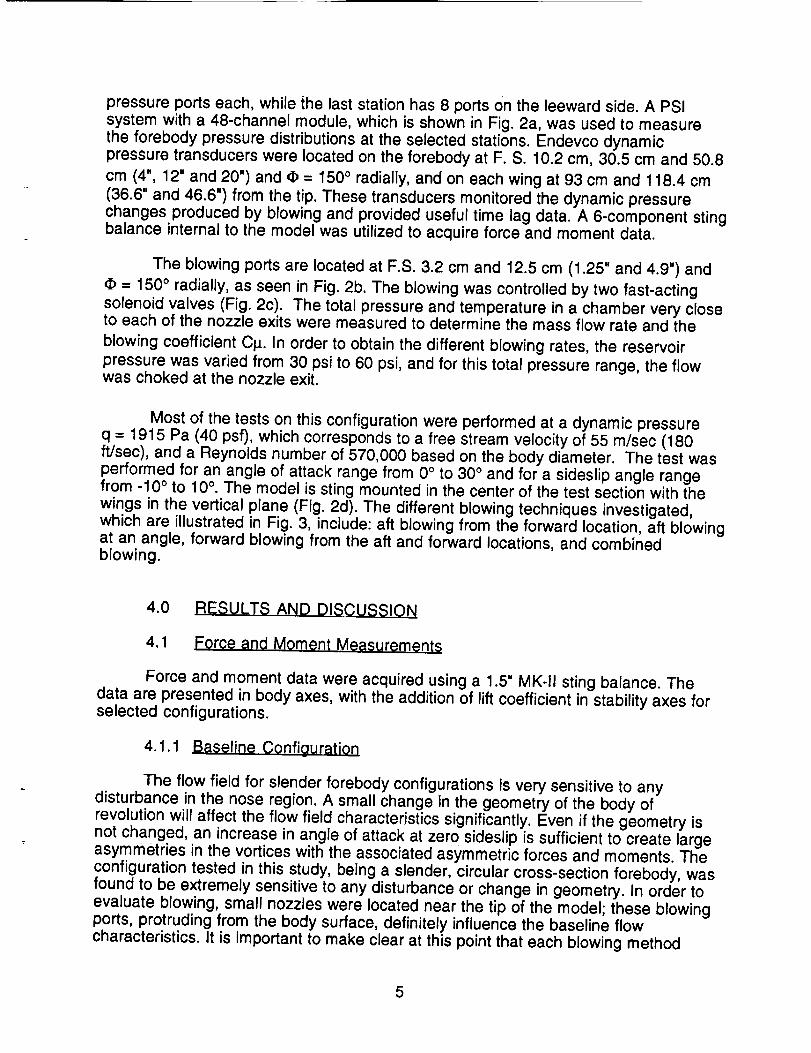
pressure ports each, while the last station has 8 ports on the leeward side. A PSIsystem with a 48-channel module, which is shown in Fig. 2a, was used to measurethe forebody pressure distributions at the selected stations. Endevco dynamicpressure transducers were located on the forebody at F. S. 10.2 cm, 30.5 cm and 50.8
cm (4", 12" and 20") and (I) = 150 o radially, and on each wing at 93 cm and 118.4 cm(36.6" and 46.6") from the tip. These transducers monitored the dynamic pressurechanges produced by blowing and provided useful time lag data. A 6-component stingbalance internal to the model was utilized to acquire force and moment data.
The blowing ports are located at F.S. 3.2 cm and 12.5 cm (1.25" and 4.9") and
(t) = 150 ° radially, as seen in Fig. 2b. The blowing was controlled by two fast-actingsolenoid valves (Fig. 2c). The total pressure and temperature in a chamber very closeto each of the nozzle exits were measured to determine the mass flow rate and the
blowing coefficient Cp.. In order to obtain the different blowing rates, the reservoir
pressure was varied from 30 psi to 60 psi, and for this total pressure range, the flowwas choked at the nozzle exit.
Most of the tests on this configuration were performed at a dynamic pressureq = 1915 Pa (40 psf), which corresponds to a free stream velocity of 55 m/sec (180ft/sec), and a Reynolds number of 570,000 based on the body diameter. The test wasperformed for an angle of attack range from 0 ° to 30 ° and for a sideslip angle rangefrom -10 ° to 10 °. The model is sting mounted in the center of the test section with the
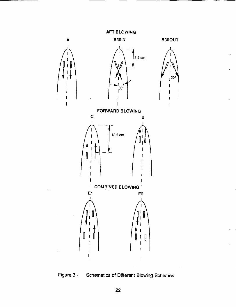
wings in the vertical plane (Fig. 2d). The different blowing techniques investigated,which are illustrated in Fig. 3, include: aft blowing from the forward location, aft blowingat an angle, forward blowing from the aft and forward locations, and combinedblowing.
4.0 RESULTS AND DISCUSSION
4.1 Force and Moment Measurements
Force and moment data were acquired using a 1.5" MK-II sting balance. Thedata are presented in body axes, with the addition of lift coefficient in stability axes forselected configurations.
4.1.1 Baseline Configuration
The flow field for slender forebody configurations is very sensitive to anydisturbance in the nose region. A small change in the geometry of the body ofrevolution will affect the flow field characteristics significantly. Even if the geometry isnot changed, an increase in angle of attack at zero sideslip is sufficient to create largeasymmetries in the vortices with the associated asymmetric forces and moments. Theconfiguration tested in this study, being a slender, circular cross-section forebody, wasfound to be extremely sensitive to any disturbance or change in geometry. In order toevaluate blowing, small nozzles were located near the tip of the model; these blowingports, protruding from the body surface, definitely influence the baseline flowcharacteristics. It is important to make clear at this point that each blowing method
5
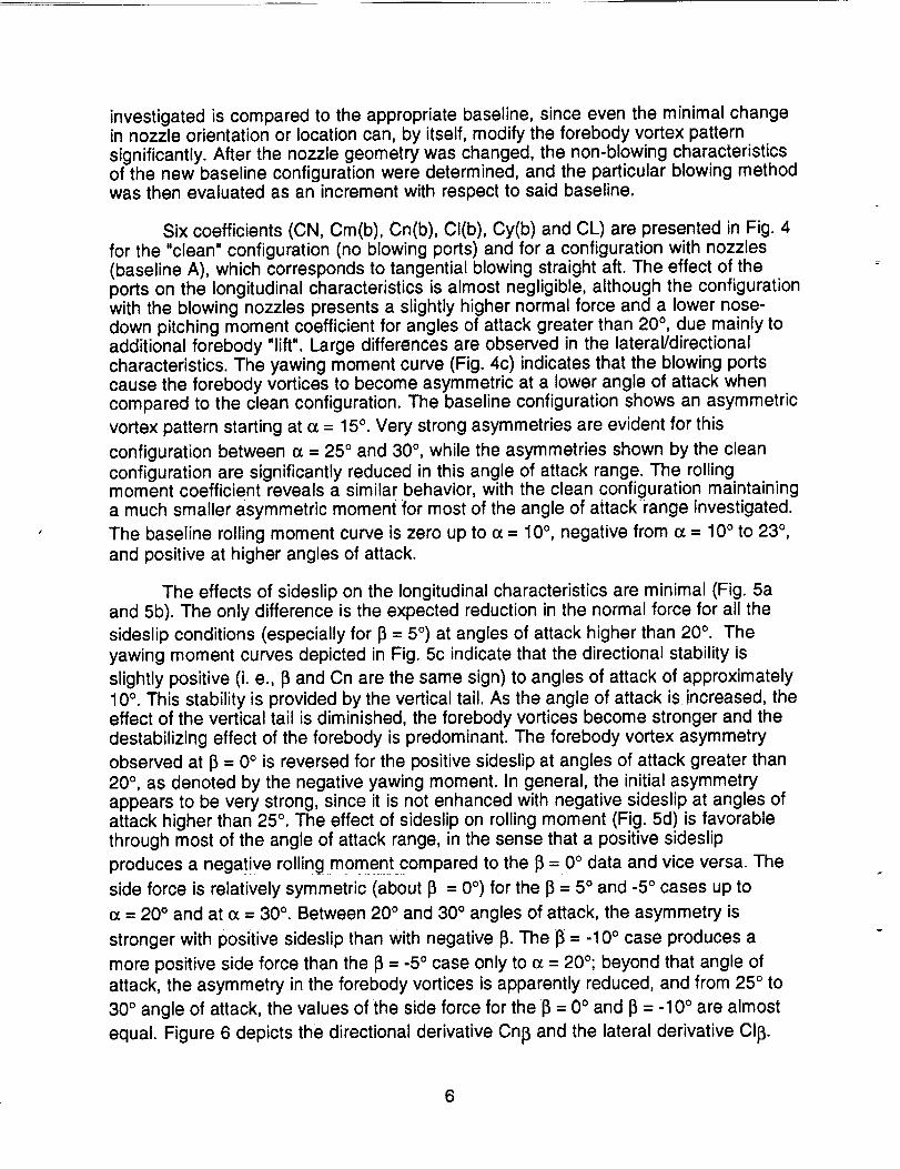
investigated is compared to the appropriate baseline, since even the minimal changein nozzle orientation or location can, by itself, modify the forebody vortex patternsignificantly. After the nozzle geometry was changed, the non-blowing characteristicsof the new baseline configuration were determined, and the particular blowing methodwas then evaluated as an increment with respect to said baseline.
Six coefficients (CN, Cm(b), Cn(b), Cl(b), Cy(b) and CL) are presented in Fig. 4for the "clean" configuration (no blowing ports) and for a configuration with nozzles(baseline A), which corresponds to tangential blowing straight aft. The effect of theports on the longitudinal characteristics is almost negligible, although the configurationwith the blowing nozzles presents a slightly higher normal force and a lower nose-down pitching moment coefficient for angles of attack greater than 20 °, due mainly toadditional forebody "lift". Large differences are observed in the lateral/directionalcharacteristics. The yawing moment curve (Fig. 4c) indicates that the blowing portscause the forebody vortices to become asymmetric at a lower angle of attack whencompared to the clean configuration. The baseline configuration shows an asymmetric
vortex pattern starting at o_= 15°. Very strong asymmetries are evident for this
configuration between (z = 25 ° and 30 °, while the asymmetries shown by the cleanconfiguration are significantly reduced in this angle of attack range. The rollingmoment coefficient reveals a similar behavior, with the clean configuration maintaininga much smaller asymmetric moment for most of the angle of attack range investigated.
The baseline rolling moment curve is zero up to o_= 10°, negative from (z = 10° to 23 °,and positive at higher angles of attack.
The effects of sideslip on the longitudinal characteristics are minimal (Fig. 5aand 5b). The only difference is the expected reduction in the normal force for all the
sideslip conditions (especially for 13= 5 °) at angles of attack higher than 20 °. Theyawing moment curves depicted in Fig. 5c indicate that the directional stability is
slightly positive (i. e., 13and Cn are the same sign) to angles of attack of approximately10 °. This stability is provided by the vertical tail. As the angle of attack is increased, theeffect of the vertical tail is diminished, the forebody vortices become stronger and thedestabilizing effect of the forebody is predominant. The forebody vortex asymmetry
observed at 13= 0 ° is reversed for the positive sideslip at angles of attack greater than20 °, as denoted by the negative yawing moment. In general, the initial asymmetryappears to be very strong, since it is not enhanced with negative sideslip at angles ofattack higher than 25 °. The effect of sideslip on rolling moment (Fig. 5d) is favorablethrough most of the angle of attack range, in the sense that a positive sideslip
produces a negative rolling moment compared to the 13= 0 ° data and vice versa. The
side force is relatively symmetric (about 13 = 0 °) for the 13= 5 ° and -5 ° cases up to
(x = 20 ° and at ec= 30 °. Between 20 ° and 30 ° angles of attack, the asymmetry is
stronger with positive sideslip than with negative 13.The 13= -10 ° case produces a
more positive side force than the 13= -5 ° case only to e_= 20°; beyond that angle ofattack, the asymmetry in the forebody vortices is apparently reduced, and from 25 ° to
30 ° angle of attack, the values of the side force for the 13= 0 ° and 13= -10 ° are almost
equal. Figure 6 depicts the directional derivative Cnl3 and the lateral derivative CII_.
6

The first plot indicates positive directional stability for angles of attack lower than 10°
(Cnl3> 0), neutral stability at (_= 10°, and negative stability for angles of attack greaterthan 10° (Cnl3< 0). The lateral stability is positive (CII3is negative) for the entire angleof attack range.
The same coefficients are presented in Fig. 7 for the tail off configuration, stillwith the same blowing nozzles (A). Again, no major changes are observed in thelongitudinal characteristics. Without the vertical tail, the main contributor to the yawingmoment change with sideslip is the forebody, and it is a destabilizing contribution. Apositive yawing moment is produced for negative sideslip angles, mainly resultingfrom the positive side force created in the forebody. The effect of sideslip on rollingmoment on this configuration is still favorable, i. e., a positive rolling moment isproduced for negative sideslips. It is important to note that the asymmetries in thebaseline flow for the tail off case are significantly reduced compared to the tail onconfiguration, indicating strong interactions between the vortices and the vertical tail.
4.1.2 Effect of Control Surface Deflections
A limited control surface deflection study was performed in order to obtainbenchmark values of the conventional control power for later comparison with thecontrol power that can be obtained with blowing. The model is provided with a rudderand with elevons on each wing (see Fig. 1) that were deflected differentially asailerons and together as an elevator. The results for two elevator deflections (30 ° and-30 °) are presented in Fig. 8, and the trends are as expected. Most of the effect isobserved in the longitudinal coefficients (CN, Cm(b) and CL), with the downwarddeflection producing an increase in normal force and a more negative pitchingmoment than the shown by the baseline case. A small effect is observed in thelateral/directional coefficients, especially in the yawing moment and side force.
Figure 9 reveals the results for the differential elevon deflections. The primaryeffect, as expected, is in the rolling moment coefficient (Fig. 9d). For a +/- 30 °deflection, the value of the rolling moment coefficient change produced isapproximately 0.035. This incremental value with respect to the baseline is almostconstant for most of the angle of attack range. A very interesting result is the couplingof the ailerons with the directional characteristics. The differential elevon deflectioninduces also a significant change in yawing moment and in side force, as shown inFigs. 9c and 9e. It appears that the differential elevon deflection is affecting the flownear the vertical tail, creating a pressure gradient over this surface with the associatedside force and yawing moment.
The deflection of the rudder, shown in Fig. 10, does not affect the longitudinalcoefficients, and minimal changes are seen in the rolling moment curves. The majorityof the changes are evident in the yawing moment and side force coefficients (Figs. 10cand 10e). A rudder deflection of 30 ° produces a change in yawing moment comparedto the baseline case of about 0.03-0.04, At angles of attack between 20 ° and 25 °, it isevident that a progressive deflection of the rudder from 15 ° to 30 ° does not necessarilyproduce a larger yawing moment. This is most likely due to the interaction of theasymmetric forebody vortices with the tail in that region. The side force shows acontinuous negative increment with respect to the baseline with rudder deflection. The
7

magnitude of the yawing moment increment is important to keep in mind for latercomparison with the changes in yawing moment obtained by blowing. The effect of therudder under sideslip conditions ([3= -10°) is presented in Fig. 11. Trends are similarto the j] = 0° case in terms of yawing moment increments. The side force curves showpositive increments for positive or negative deflections at angles of attack greater than20°, denoting changes in the position of the center of pressure. At angles of attackabove 15°, the positive deflection of the rudder results in a positive yawing momentincrement (as desired), but in near-zero or positive side force increment, implying thatthe center of pressure shifts forward and the contribution of the forebody is increasedin a direction opposite to the tail contribution. From the yawing moment data, therudder is still effective, but the overall flow field changes sufficiently to also produce apositive side force. The reason for this is not clear. The flow visualization experimentsin the water tunnel showed that, at angles of attack higher than 25 °, the forebodyvortices burst close to the vertical tail, so it is possible that interactions between therudder and the vortex's burst point might influence the flow field in the forebody region.The effect of the rudder deflection on the rolling moment is larger than for the zerosideslip case, and produces a negative rolling moment increment for rudderdeflections in either direction. Perhaps the rudder deflection is influencing the flow onthe wing near the trailing edge sufficiently to produce negative roll inputs in bothcases.
4.1.3 Effect of Blowing (Aft Blowing, Nozzl_ A)
The first blowing technique evaluated was blowing straight aft, tangentially tothe forebody surface, from the forward location (see Fig. 1). Blowing from the left andright sides, and from both sides simultaneously, were investigated extensively. Theresults for left blowing appear in Fig. 12, and as expected, blowing does not affect thelongitudinal characteristics significantly. The only change observed is a smallreduction in normal force for the high blowing coefficient cases at angles of attackgreater than 22 °. Figs. 12c-e reveal the effect of left side blowing on thelateral/directional coefficients. Blowing is not effective at angles of attack below 15°; at
oc = 15% blowing starts producing a nose-left or negative yawing moment. Confirmingthe water tunnel test results, the blowing jet appears to be delaying separation on thatside of the forebody, inducing a left-vortex-low pattern and the associated negativeside force and yawing moment coefficients (with respect to the baseline). Between 15°and 23 ° angles of attack, the magnitude change in yawing moment increases as theblowing coefficient is increased and the trends appear to be well-behaved. Blowing at
the highest CI_ = 0.0015 induces a negative change in the yawing moment coefficient
of about 0.06 at o_= 20 °, larger than the increment produced by a 30 ° rudderdeflection. The effect of blowing on the rolling moment coefficient appears to be alsofavorable, in the sense that it reduces the asymmetric rolling moment, especially at the
highest blowing coefficient. At this Ct_, a positive rolling moment increment is observed
between o_= 15 ° and 23 °, while a negative increment is observed between 23 ° and30 ° angles of attack. There is obviously some interactions of vortices with either the tailor wing surfaces at angles of attack between 20 ° and 25 °, since the direction of therolling and yawing moments reverse. The side force and the increments in side force,
8

yawing moment and rolling moment coefficients with respect to the baseline areplotted in Figs. 12e-h.
Figure 13 shows the effect of blowing on the right side of the forebody, andagain, no changes are observed in the longitudinal characteristics. The effects on thelateral/directional characteristics are quite different than for the left side blowing case.Even though a small positive side force is generated at angles of attack higher than25 °, the yawing moment increment generated with respect to the baseline is negative,as in the left side blowing case. This could be due to several reasons, such as, forexample, the initial vortex asymmetries and the location of the blowing ports. The initialforebody asymmetry, as denoted by the baseline yawing moment curve, is very strong,and apparently, blowing on this side (which means blowing into the vortex that isalready closest to the forebody) and in this angle of attack range cannot enhance thatasymmetry much more. The blowing ports are probably located too far forward, andtherefore, very close to each other, so the jets are actually influencing the flowcharacteristics on both sides of the forebody and the net effect of blowing isdiminished. The impact of right side blowing on the rolling moment coefficient isminimal.
The changes in the lateral/directional characteristics produced by blowing onboth sides simultaneously are shown in Fig. 14. This technique appears to be veryefficient for eliminating the initial natural asymmetries. The advantage of this scheme isthe fact that significant yawing moment and rolling moment coefficient increments(0.03 and 0.02, respectively) can be obtained when blowing at the minimum blowing
coefficient (Cp. = 0.00075). Actually, the yawing and rolling moment coefficientsobtained when blowing at the two lowest rates present almost zero values throughoutthe entire angle of attack range. The mass flow rates corresponding to these blowingcoefficients appear to be well within the practical limits of full size blowingrequirements, based on studies related to fighter configurations with available enginebleed for the required pressurized air source.
When the vertical tail is removed, blowing strongly influences the vortex flowfield and it appears that the trends are better behaved than for the tail on configuration,probably because the interaction between the vortices and the vertical tail is notpresent. Fig. 15 shows left-hand-side blowing for the no tail configuration. At theminimum blowing coefficient, the initial asymmetries in yawing and rolling moment are
totally eliminated. As CI_ is increased, a negative yawing moment is obtained, whichincreases with both angle of attack and blowing rate. At 30 ° angle of attack and the
maximum blowing rate (CI_ = 0.0015), left side blowing induces a negative change of0.09 in yawing moment coefficient with respect to the baseline. Unfortunately, similaryawing moment increments are not obtained when blowing on the right side (Fig. 16).In general, left, right and simultaneous blowing produce a negative, positive andalmost zero yawing moments, respectively, as seen in Fig. 16b. However, the initialasymmetry presented by this configuration showed a positive yawing moment,therefore, as in the tail on case, the increment produced by right side blowing isminimal. Apparently, blowing on the right side from this port location and at theseblowing coefficients is not sufficient to enhance the vortex asymmetry at zero sideslip.
9

The effect of blowing under sideslip conditions was also investigated. Figure 17reveals the results for blowing at 13= 5°. Left blowing is destabilizing in yawingmoment, as denoted in Fig. 17a, in which a negative yawing moment increment isobserved for most of the angle of attack range for a nose-left attitude. Blowing on theright side at the highest blowing coefficient (CI_= 0.0015) induces a positive orstabilizing yawing moment increment between (_= 20° and 25°, that tends to bring thenose back to a zero sideslip condition. At 13= -5° (Fig. 18), blowing on the left side atC_ = 0.0015 ais0 produces a n0se-left yawing moment which has an stabilizing effect,and blowing on the right side is not effective (Fig. 18d-f). Not much change in therolling moment coefficient is observed. Depicted in Fig. 19 are results for 13= -10°.Blowing on the left side at the maximum CI_tends to reduce the initial asymmetry up to25° angles of attack, as shown in Fig. 19a. The trends are not well behaved, probablybecause there are strong interactions between the forebody vortices and the verticaltail. Blowing on the right side (Fig. 19e) enhances the asymmetry and produces aconstant positive increment in yawing moment (destabilizing) of about 0.02 from(x = 20° to 30°.
4.1.4 Effect of Blowing (Aft Blowing. Nozzles B301N and B30OUT)
It was reported in Ref. 7 that by rotating the nozzles inboard 60 °, the magnitudeof the yawing moment increment obtained by blowing was increased significantly. Inan effort to investigate the sensitivity of blowing to a change in the nozzle angle, theports were turned inboard 30 °. This experiment illustrated how sensitive thisconfiguration is to changes in geometry. Just by changing the orientation of thenozzles, the baseline flow is modified substantially, as denoted by the yawing androlling moment curves in Figs. 20a and 20b. Not only the magnitude of the initialasymmetries is modified, but their sign (i.e., the vortex orientation) is totally changedwith respect to the previous baseline (A) as well. Later in the test, when the nozzleangle was changed to 45 ° inboard, the non-blowing flow characteristics wereinfluenced in such a way that the dynamics of the model/sting system were totallymodified. The model vibrated so violently with this nozzle configuration that data couldnot be recorded at this condition.
Since the initial asymmetry for this configuration presents a left-vortex-lowpattern, as indicated by the negative values of the yawing moment curve, blowing onthe left side is not very effective. A negative yawing moment increment of about 0.02 isobtained for angles of attack between 20 ° and 30 °. Blowing on the right side produces
a very large positive change in side force up to (_ = 27 °. That positive change in side
force induces a positive change in yawing moment, however, the trends are very
unpredictable, as seen in Fig. 20e. At (z = 20 °, the largest change in yawing moment is
produced when blowing at the lowest rate (C_ = 0.00075). At (x = 25 °, the increments
are minimum, and at 30 ° angle of attack, a change in yawing moment of approximately
0.08 is obtained when blowing with the highest CI_ = 0.0015. This increment is muchlarger than any change induced by the previous blowing configuration, denoting theinfluence of blowing direction. A positive rolling moment increment is observed for the
10

right blowing case between (z= 22 ° and 30 °. It is evident that the orientation of thenozzles is an extremely important parameter in the blowing process.
The blowing nozzles were turned outboard 30 ° and the results are presented inFig. 21. The non-blowing flow field characteristics are again different than for previousconfigurations. The blowing ports are apparently acting as small strakes, reducing theinitial asymmetries, especially in the yawing moment coefficient shown in Fig. 21a. Thecoefficient has an almost zero value for most of the angle of attack range. This blowingscheme did not prove very efficient. Ref. 7 reported that outboard blowing creates aforce away from the blowing side. Some evidence of that trend is observed in thesedata for some blowing coefficients and angles of attack, but in general, this form ofblowing does not appear to provide an advantage over the previous blowing schemesinvestigated.
4.1.5 Effect of Blowing (Forward Blowing, Nozzles C and D)
Forward blowing was also evaluated as a possible means of lateral/directionalcontrol. The results of forward blowing from the aft location are presented in Fig. 22.Left blowing induces a negative yawing moment, and it seems to be more efficientthan right blowing. Both of them produce similar negative yawing moment changes at
CI_ = 0.0015, but left blowing is more efficient at the lowest blowing coefficients.
Neither left nor right blowing from this location is sufficient to enhance the vortexasymmetry and produce a positive change in yawing moment. It is difficult to speculateon the mechanism of this blowing technique, but it appears that both jets areinfluencing more the right side of the forebody, promoting an earlier separation on thatside and forcing the initial right-vortex-low pattern to be symmetric. The results fromblowing on both sides simultaneously seem to be independent of mass flow rate, andthe net effect is to produce an almost zero yawing and rolling moments (Fig. 22g and
22h). Trends at 13= -10 ° are shown in Fig. 23, and as expected from results at 13= 0 °,left blowing is more effective than right blowing. In general, blowing from one side ofthe forebody loses effectiveness when the aircraft is yawed too much towards the sideof the blowing port. Blowing on the left side can reverse the right-v0rtex-lowasymmetry, and blowing on the right side enhances the asymmetry but only for anglesof attack between 25 ° and 30 o and at the lower blowing rates (Figs. 23d and 23e).
The results for forward blowing from the forward location agree with the watertunnel test (Volume I of this Final Report), and with the results presented in Ref. 2 for ageneric fighter configuration. At high angles of attack, and at low blowing coefficients,forward blowing produces the opposite effect when compared to aft blowing, i.e.,
blowing on the left side at CI.[ = 0.00075 produces a positive (nose-right) change inyawing moments for angles of attack greater than 25 ° (Fig. 24a). As the blowingcoefficient is increased, this trend is reversed and a negative increment is produced.Between 15 ° and 25 ° angles of attack, however, the effect of left and right blowing onthe yawing moment is the same, and in both cases, the asymmetry is completelyeliminated at the highest blowing coefficient. For angles of attack greater than 25 °,
blowing at C_ = 0.0015 on the left side (Fig. 24a) and on the right side (Fig. 24d),induces negative and positive increments in yawing moment, respectively. The effect
of forward blowing at the highest CI_ on side force and rolling moment coefficients is
11

similar for left or right blowing, probably because with the blowing nozzles so farforward and therefore, very close to each other, the forward jet acts like a vortex spoilerand affects both left and right vortices almost equally. The jets are apparently too farforward to be useful.
4.1.6 Effect of Blowing (Combined Blowing. Nozzles E1 and E2)
This technique combines aft blowing on one side (left) and forward blowing onthe other side (right) applied simultaneously. The concept behind this blowing methodis to delay separation on the left side (by means of aft blowing), and to promote earlyseparation on the opposite side (by means of forward blowing). Results are revealedin Fig. 25, and a negative increment in the lateraVdirectional coefficients is produced.These changes appear to be better behaved than in all the other techniques testedbefore. An increase in blowing coefficient causes an almost proportional increase in
the increments produced, and at CI_ = 0.0015, the initial asymmetries are completelyeliminated. Limitations in the testing time did not allow for evaluation of the othercombination, i.e., aft blowing on the right side and forward blowing on the left side.
A quick test on blowing aft and forward on the same side simultaneously (seeFig. 3) was also performed but only for the two lower blowing coefficients (Fig. 26).Negative increments are obtained when blowing at these two rates, except near
o_= 25 °. It can be speculated that for blowing to be effective over the entire angle ofattack range, a combination technique that uses two jets to reinforce the effects ofblowing might be the best solution for obtaining maximum yawing moment inputs.
4.2 Pressure Measurements
Static pressures were measured on the forebody at three different stationsusing a PSI electronic scanner. The pressure distributions are presented at selectedangles of attack, both for the non-blowing baselines and for all the blowing techniques
investigated, and they are plotted against azimuth angles. Ports with azimuth angles (t)
between 1° and 179 ° are on the right side of the forebody; the left side contains ports
with • between 181° and 359 ° ((t) = 0 ° = 360 ° is the windward meridian).
4.2.1 Baseline Configuration
The pressure distributions at the three forebody stations for the non-blowingcase of the configuration with nozzle A (blowing straight aft) are presented in Fig. 27.
The pressures show a symmetric vortex flow field for the oc= 15 ° case, and a
asymmetric pattern is evident starting at 20 ° angle of attack, as denoted by the lowerpressures on the right side of the forebody. This indicates a higher suction on the rightside, and a right-vortex-low pattern, confirming the force and moment measurements,where the yawing moment curve presented a large positive value for angles of attackgreater than 15 ° (see Fig. 4c).
The pressure distributions for the same baseline at different sideslip conditions
are shown in Figs. 28, 29 and 30 for the 13= 5 °, -5 ° and -10 ° cases, respectively. The
12

13= 5° and -5 ° cases present mirror images only for the p0rts located on the windward
side. The pressures at the ports located between ¢ = 72 ° and 288 ° reveal different
aspects of the flow, such as vortex position, separation, etc., and because of thenatural asymmetries in the flow at zero sideslip, very different pressure distributions
can be expected in that forebody region for the 13= 5 ° and -5 ° cases. The pressures
show an almost symmetric vortex pattern for the [3 = 5° case up to 25 ° angles of attack.
At e_= 30 °, the asymmetric vortex pattern switches sign (left-vortex-low). At -5 ° sideslip,the asymmetry indicated by the pressures is similar to the baseline case, with a right-
vortex-low pattern. This asymmetric pattern, however, is not enhanced for the 13= -10 °case, as seen in Fig. 30. The asymmetry is apparently reduced, and the vorticesappear to be interacting with the opposite forebody sides, as denoted by the pressuredistribution at station 3, where a much lower pressure is observed on the left side ofthe forebody, contradicting the distributions observed in stations 1 and 2 for the samecondition.
The forebody pressure distribution for the tail off case, shown in Fig. 31, reveals
similar characteristics as the tail on case up to 25 ° angles of attack. At e_= 30 °, thedistribution at station 2 is slightly different, and the asymmetric pattern observed is notas dramatic as for the tail on configuration. The interactions between the forebodyvortices and the vertical tail apparently do not influence the forebody vortex flow fieldat angles of attack lower than 30 °.
4.2.2 Effect of Blowing (.Aft Blowing. Nozzle A)
The effect of blowing at o_= 15 ° and 20 ° are shown in Figs. 32 and 33,respectively, and no major changes are observed. The three blowing schemes (left,
right, both) produce a slight increase in pressure at e_= 15 °. At e_= 20 °, an indication ofthe effect of blowing is noticed, as the initial asymmetry observed in stations 2 and 3 is
eliminated completely. At ec= 25 ° and 30 ° (Figs. 34 and 35), the pressure distributions
confirm the force and moment measurements. Starting with the initial right-vortex-lowasymmetry, left blowing makes the pressure distribution symmetric when blowing at
the highest C_ = 0.0015, as evident in stations 2 and 3 in Figs. 34a and 35a. Not much
effect is observed for right blowing, as indicted in Figs. 34b and 35b for _ = 25 ° and
30 °, respectively. Simultaneous blowing (Fig. 35c) reduces the large initial asymmetry
at 30 ° angle of attack at the lowest blowing coefficient (CI_ = 0.00075). A combinationof the effects of left and right blowing appears to be beneficial in this case.
The hysteresis in the blowing process was also investigated, and it is illustratedin Fig. 36 at o_= 30 °. Blowing was applied on the left side and the mass flow was
increased to the maximum rate. The results in Fig. 36a (increasing rate portion) agreewith the pressure distributions depicted in Fig. 35a, showing good repeatabilitybetween similar type runs (in both runs, the mass flow of the blowing jet was increasedfrom zero to the maximum rate). The mass flow rates were then decreased until zero
blowing, and the pressures show some hysteresis (Fig. 36b). Changes in pressure onthe leeward side of the forebody are notas evident as in the previous figure (36a), and
13

the non-blowing case (baseline A) presents a slightly different vortex pattern. Theasymmetry still has the same orientation, but the magnitude is decreased.
Figures 37 and 38 show the effects of blowing at 25° and 30° angles of attack,respectively, for the tail off configuration. As shown by the force measurements, leftblowing produces a large change in side force and yawing moment at _= 30°. Figure38 appears to confirm those results; left blowing at C_ = 0.00125 produces a largechange in the pressure distribution, reversing completely the initial asymmetry, asobserved in stations 2 and 3.
4.2.3 Effect of BIQwing (Aft Blowing. Nozzles B301N and B30OUT)
The effect of changing the orientation of the nozzles in the vortex flow field isclearly shown also by the forebody pressure distribution. By turning the nozzlesinboard 30 °, the baseline characteristics are changed completely with respect to theprevious case (nozzle configuration A), and a left-vortex-low asymmetry is observed at
30 ° angle of attack. Left-hand-side blowing produces small changes at e_= 25 °, asshown in Fig. 39a. The large positive changes in side force produced by right blowingare reflected in the pressure changes in stations 2 and 3 shown in Fig. 39b. At 30 °angle of attack, the asymmetry is slightly enhanced when blowing on the left side, andtotally reversed when blowing on the right side (Fig. 40b). Large changes in pressuresare observed in all the stations, but especially in stations 2 and 3. The pressuresdecrease on the right side and increase significantly on the left side; higher suction iscreated on the right side and a large positive yawing moment is induced.
When the nozzles are turned outboard 30 °, it was speculated that these blowingports physically act as small strakes, eliminating the large forebody vortexasymmetries. Figs. 41 and 42 show pressure distributions for this configuration at
= 25 ° and 30 °, respectively, and an almost symmetric pattern is observed for thebaseline at both angles of attack. However, the effects of blowing are not as dramaticas the changes in the baseline flow, as the force and moment measurements had
shown in section 4.1.4. At oc= 25 °, the effect of blowing is minimum. At e_= 30 °, rightand left blowing create opposite asymmetries. Left blowing produces a left-vortex-lowasymmetry, as shown in Fig. 42a, while right blowing induces a right-vortex-lowasymmetry (Fig. 42b).
4.2.4 EffeCt of BIQwing (Forward Blowing, Nozzles C and D)
The local effect of the blowing jet in some forebody areas is evident in Fig. 43,
which shows pressure distributions for forward blowing with nozzle C at e_= 25 °. Themajority of the changes are seen in station 1, which is in front of the blowing ports. Leftblowing (Fig. 43a) clearly affects the left leeward side of the forebody, while rightblowing does the opposite (Fig. 43b). Apparently, the blowing jet is promoting an earlyseparation on the blowing side; however, this behavior is not being reflected on sideforce or yawing moment changes, probably because this is only a local effectproduced by the jets in a small forebody region. Behind the ports (stations 2 and 3),small changes are produced by left blowing that tend to decrease the initial
14
asymmetry, while right blowing does not show any major effect on the pressures. At
(_ = 30 ° (Fig. 44), similar trends are observed.
Figures 45 and 46 show forward blowing from the forward location at (z = 25 °
and 30 °. No major effects on the pressure are noticed at (_ = 25 °. The results at (z = 30 °reveal again the disadvantage of this method, i.e., changes are not well-behaved andcontrol reversals with blowing rate are observed. This is clearly illustrated in Fig. 46b,especially in station 2. Starting with the non-blowing case, that presents a slight right-
vortex-low asymmetry, forward blowing (right side) at the lowest C_ = 0.00075,
completely reverses the asymmetry, inducing a negative yawing moment, as seenpreviously in the force measurements. On the other hand, by blowing at the highest
CI_ = 0.0015 on the same forebody side, the asymmetry is reinforced, and a positive
yawing moment increment is obtained.
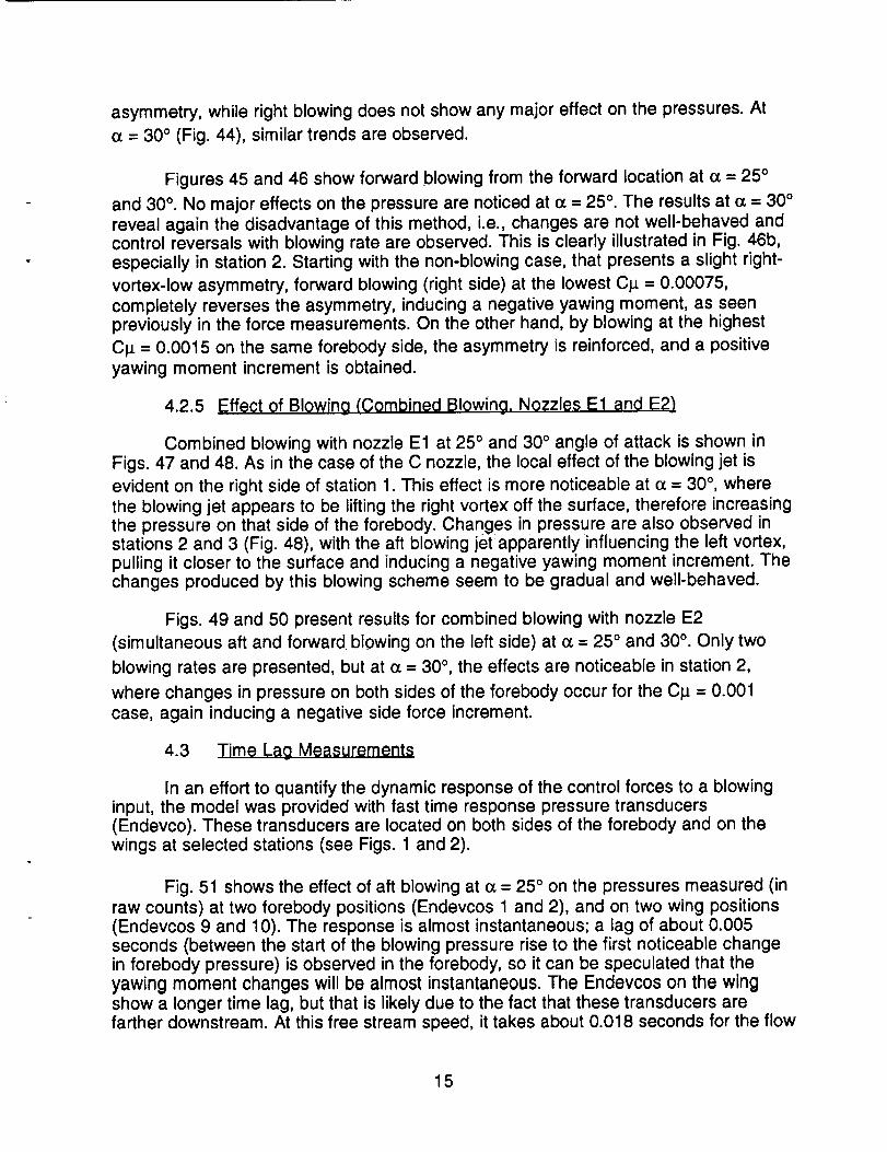
4.2.5 Effect of Blowing (Combined Blowing, Nozzles E1 and E2)
Combined blowing with nozzle E1 at 25 ° and 30 ° angle of attack is shown inFigs. 47 and 48. As in the case of the C nozzle, the local effect of the blowing jet is
evident on the right side of station 1. This effect is more noticeable at (z = 30 °, wherethe blowing jet appears to be lifting the right vortex off the surface, therefore increasingthe pressure on that side of the forebody. Changes in pressure are also observed instations 2 and 3 (Fig. 48), with the aft blowing jet apparently influencing the left vortex,pulling it closer to the surface and inducing a negative yawing moment increment. Thechanges produced by this blowing scheme seem to be gradual and well-behaved.
Figs. 49 and 50 present results for combined blowing with nozzle E2
(simultaneous aft and forward blowing on the left side) at o_= 25 ° and 30 °. Only two
blowing rates are presented, but at o_---30 °, the effects are noticeable in station 2,
where changes in pressure on both sides of the forebody occur for the C_ = 0.001
case, again inducing a negative side force increment.
4.3 Time L_g Measurements
In an effort to quantify the dynamic response of the control forces to a blowinginput, the model was provided with fast time response pressure transducers(Endevco). These transducers are located on both sides of the forebody and on thewings at selected stations (see Figs. 1 and 2).
Fig. 51 shows the effect of aft blowing at (_= 25 ° on the pressures measured (inraw counts) at two forebody positions (Endevcos 1 and 2), and on two wing positions(Endevcos 9 and 10). The response is almost instantaneous; a lag of about 0.005seconds (between the start of the blowing pressure rise to the first noticeable changein forebody pressure) is observed in the forebody, so it can be speculated that theyawing moment changes will be almost instantaneous. The Endevcos on the wingshow a longer time lag, but that is likely due to the fact that these transducers arefarther downstream. At this free stream speed, it takes about 0.018 seconds for the flow
15

to reach that Endevco location on the wing. Figure 51b shows that the changes inpressure are observed about 0.020 seconds after the blowing pressure starts buildingup, and the maximum pressure changes occur about 0.020 seconds after the setblowing pressure is reached. The response of the rolling moment gage (in raw counts)is also plotted in this figure, and it shows a very fast response (about 0.010 secondsafter the left and right pressures start changing).
Fig. 52 shows similar data at e_= 30°, and the pressures on the forebody startchanging almost immediately after blowing is turned on. Depicted in Fig 52b is theresponse of the side force gage (in raw counts), and again, a very fast response isobserved. It appears that the mean value of the side force change is obtainedapproximately 0.015 to 0.020 seconds after the blowing pressure reaches itsmaximum value. This time response is consistent with data presented in Ref. 7. Thetransducers located on the wing, in this case presented at two different stations, showsimilar behaviors. The Endevcos located at the aft wing station appear to respond0.005 seconds later than the ones at the forward station (Figs. 52c and 52d), but again,that is likely due to the time it takes the free stream flow to reach the second station.When blowing on the right side (Fig. 53), it is seen that the changes in the forebodypressures near the blowing ports are very rapid, as denoted by the instantaneouspressure change measured by Endevco 2. Force and moment measurements showedthat this blowing scheme did not produce any changes in yawing or rolling moments,and that is confirmed by the outputs of Endevco 9 and 10, where no changes inpressure are noticeable in Fig 53b. The simultaneous blowing technique (Fig. 54)shows a very fast response also. Similar behavior is observed at I] = -10 ° in the
forebody transducers for left blowing (Fig. 55a) and right blowing (Fig. 55b).
Finally, Fig. 56 shows results for forward blowing (Nozzle C). The first twographs illustrate the response of a transducer that is located in front of the blowingnozzle, clearly showing the unsteadiness of the signal when blowing is on. Thetransducers located on the forebody behind the blowing ports (Figs. 56c and 56d) andon the wings (Figs. 56e and 56f) present similar time responses as the observed forthe other blowing scheme, i.e., aft blowing.
According to the results obtained in this part of the experiment, it can bespeculated that the response of the control forces created by blowing is almostinstantaneous. The time for the configuration flow field to react to a blowing input at thefront of the forebody is approximately the time required for the disturbance to travel thelength of the model. No major time lags or overshoots were observed for any of theblowing techniques investigated.
5.0 CONCLUSIONS
A detailed investigation of the effect of various jet blowing schemes on a NASP-type configuration was performed in a wind tunnel. The main conclusions of this studycan be summarized as follows:
1. The configuration investigated, having a slender forebody, is extremelysensitive to small changes in forebody geometry and to disturbances in the flow field.
16

The sole presence of the small blowing ports near the tip of the forebody can causestrong asymmetries at angles of attack higher than 15 °.
2. Blowing straight aft is capable of producing significant changes in thelateral/directional characteristics for angles of attack greater than 15 °. These changesare strongly dependent on the initial flow field asymmetries. Left side blowing at
C_ = 0.0015 produces a negative change in yawing moment, with a magnitudecomparable to a rudder deflection of 30 °. The blowing jet is delaying separation on theleft side of the forebody, creating a higher suction on that side and a negative sideforce. Right side blowing, however, does not produce a similar increment in yawingmoment and side force, probably because the large initial vortex asymmetry (right-vortex-low) cannot be enhanced much more at these blowing coefficient and angle ofattack ranges. Simultaneous blowing eliminates the vortex asymmetry at the lowestC_ = 0.00075.
3. In addition to angle of attack and blowing rate, aft blowing appears to bevery sensitive to changes in nozzle direction. By turning the nozzles inboard 30 °, theyawing moment increments produced by blowing are magnified at some angles ofattack. The behavior of this blowing technique is still very dependent on blowing side.
4. Forward blowing can also affect the lateral/directional characteristics ofthis configuration but, in general, the results present unpredictable and non-lineartrends, with large control reversals in the angle of attack range investigated. Thisconfirms the results obtained in the water tunnel investigation.
5. Combined blowing, i.e., blowing aft on one side and forward on the other,reveal interesting results, with significant changes in side force, yawing moment androlling moment coefficients. These increments are gradual and well-behaved for thiscombination (aft blowing on the left side and forward blowing on the right side), buttime limitations did not allow for testing the other combination.
6. The forebody pressure distributions present excellent agreement with theforce and moment measurements. These pressures also show interesting aspects ofthe flow, such as forebody vortex position, local effects of the blowing jets, etc.
7. The dynamic response of the forces and pressures to the blowing inputswas also evaluated. Neither of the blowing techniques investigated presents majortime lags or overshoots. The response of the pressures on the forebody is almostinstantaneous, while the wing transducers show a lag that correspond to theconvective time, i.e., the time it takes the free stream flow to reach those wing stations.
In general, it was shown that blowing can be used to generate additional controlforces and moments that would improve the handling qualities of a NASP-typeconfiguration. The results, however, also show that an extensive and thoroughoptimization of some of the blowing parameters (especially port location and direction)is still necessary to take this control technique to a flight test program. Thisinvestigation definitely showed that, first of all, the blowing rates necessary to obtainadditional forces and moments to enhance controllability are well within the practicallimits of full size mass flow requirements. Secondly, the increments in forces and
17

moments are comparable, and sometimes larger, than a full rudder deflection. Eventhough the rudder of this configuration is still effective at 30 ° angle of attack, blowingoffers the possibility of decreasing the size of the vertical tail, therefore reducing weightand drag and improving high speed performance.
6.0 A(_KNQWLEDGMENT$
Support for this work is provided by NASA Ames Research Center undercontract NAS2-13196. The technical monitor is Mr. Larry Meyn of the Fixed-WingAerodynamics Branch. We would also like to acknowledge the efforts of Mr. Bert Ayersfor his high quality work in constructing the wind tunnel model.
7.0 REFERENCES
1. Murri, D.G. and Rao, D.M., "Exploratory Studies of Actuated ForebodyStrakes for Yaw Control at High Angles of Attack," AIAA-87-2557-CP, August 1987.
2. Malcolm, G.N., Ng, T.T., Lewis, L.C., and Murri, D.G., "Development ofNon-Conventional Control Methods for High Angle of Attack Flight Using VortexManipulation," AIAA-89-2192, July 31-August 1'2, 1989.
3. Zilliac, G., Degani, D., and M. Tobak, "Asymmetric Vortices on a SlenderBody of Revolution," AIAA-90-0388, January 1990.
4. Moskovitz, C., Hall, R., and DeJarnette, F., "Experimental Investigation ofa New Device to Control the Asymmetric Flowfield on Forebodies at Large Angles ofAttack," AIAA-90-0068, January 1990.
5. Ng, T. T. and Malcolm, G. N., "Aerodynamic Control Using ForebodyStrakes," AIAA-91-0618, Jananuary 1991.
6. Su_.rez, C. J., Malcolm, G. N., Ng, T. T., "Forebody Vortex Control withMiniature, Rotatable Nose-boom Strakes", AIAA-92-0022, January 1992.
7. Guyton, R. W., Maerki, G., "X-29 Forebody Jet Blowing", AIAA-92-0017,January 1992.
8. LeMay, S. P., Sewall, W. G., Henderson, J. F., "Forebody Vortex FlowControl on the F-16C Using Tangential Slot and Jet Nozzle Blowing", AIAA-92-0019,January 1992.
9. Tavella, D.A., Schiff, L.B., and Cummings, R.M., "Pneumatic Vortical FlowControl at High Angles of Attack," AIM-90-0098, January 1990.
10. Rosen, B. and Davis, W., "Numerical Study of Asymmetric Air Injection toControl High Angle-of-Attack Forebody Vortices on the X-29 Aircraft," AIAA-90-3004,August 1990.
18

11. Ng, T. T. and Malcolm, G. N., "Aerodynamic Control Using ForebodyBlowing and Suction," AIAA-91-0619, January 1991.
12. Ng, T. T., Su_rez, C. J., Malcolm, G.N., "Forebody Vortex Control UsingSlot Blowing," AIAA-91-3254, September 1991.
13. Ng, T. T., "Aerodynamic Control of NASP-type Vehicles Through VortexManipulation", Eidetics International TR89-009, 1989.
19
,=0
"dLU
¢'3
I--
a3
O3
z
t-_
¢D
• _m.B
o
@
-g_X
¢D
¢,')
c_
¢./3
e"
.C
O9
u
-g
r-e.-
I--"O¢-
o
E¢D¢-
O3
!
C_
u_
20

a_
_m
_m
o
o_m
!
C_J
LL
21
A
=
I
AFT BLOWING
B301N
I3,2 cm
/
--_ r"130°
I
FORWARD BLOWING
C D
-- t12.5 cm
I
I
I I
COMBINED BLOWING
E1 E2
t',!]I
B3OOUT
I
I
Figure 3 - Schematics of Different Blowing Schemes
22

CN
INFLUENCE OF BLOWING PORTS ON NORMAL FORCE
1.4 .... _1.... i1'-...... + ........ __--ITH PORTS ........................................................................................................................
1.2 - _
__--D- CLEAN
1 ............................_.............................._.............................'..............................'............................"
........................... ; .............................. ; ............................. i .............................. ; ...... 7 .................. ,'-............................0.8 _ _ _ ' ,- i
0.6 .......................................................................................................: .................................................................: i _ ," i i
0.4 ..........................._.............................- ..................... _"" ........................_............................._............................
0.2 ...........................+.............".............;.............................i.............................._.............................÷............................
0-C
| J i l i t ! i i i i i [ i s I i 1 i i i I i t J •
-0.2 i i
0 5 10 15 20 25 30
ANGLE OF ATTACK [deg.]
a)
INFLUENCE OF BLOWING PORTS ON PITCHING MOMENT
o_t ............ ' .... _+ ,+.... jtl- ++ lLi i .....................................................d:
o.1____1 [] CLEAN i + + ++cm(+) ..::..:.......-.....................................+.............................+..............................+..............................i..........................k b)
0.05 ............................i...............................................................................................................................;.....................
-0.05 .................................................................................................................................................................;.......
]-01
o,, ............................i ]I i i i I l ] I i I i z ] , [ ] , I I I I I I I I !-0.2 i t
0 5 10 15 20 25 30
ANGLE OF ATTACK [deg.]
Figure 4 - Influence of Blowing Ports on Forces and Moments(No Ports vs. Baseline A)
23

0.16
0.12 -
Cn(b)
0.08 .................................................................................................................................................................................
o.o4- i __! .............._........y. .........;.........................0 -1 ......................-_..........=..=....-..._........._-- ...:..z....=._._.-_.-.".-......_............................1............._....7..`...
-0.04 ..................................................................................................................................................................................
_O 0 8
• I I I
INFLUENCE OF BLOWING PORTS ON YAWING MOMENT
• l liI
WITH PORTS
--[3- CLEAN
0 5 10 15 20 25 30
ANGLE OF ATTACK [deg.]
c)
Cl(b)
0.16
0.12 -
INFLUENCE OF BLOWING PORTS ON ROLLING MOMENT
i,[
WITH PORTS
--[3- CLEAN
---- ............................................................ ; ..........................................................
0.08 ............................ ,............................................................,.........................................................................................
0.04 .................................................................................................................................................................................
i!
-0.04 ........................................................... _............................................................_............................._............................
-0.08 .... 1 ''', l .... ,,,, i , , , 1 , , , l it I
0 5 10 15 20 25 30
ANGLE OF ATTACK [deg.]
d)
Figure 4 - Continued
24

INFLUENCE OF BLOWING PORTS ON SIDE FORCE
t " I I; i
'_e_ WITH PORTS--G- CLEAN
.1 ...................................................................................................................................................................................
o.os............................T..............................!.............................i......................... ..........'"
-o.o5............................T.............................7.......................................................................................................................: i
•_
I I I l ' .... ! ........ ' ...... i 1
01° I I I
0.15 -
Cy(b)
0 5 10 15 20 25 30
ANGLE OF ATTACK [deg.]
e)
1.4 "
1.2 --
CL
1
0.8
0.6
0.4
0.2
01
-0.2
INFLUENCE OF BLOWING PORTS ON LIFT (STABILITY AXIS)
.... I .... I .... I .... - .... • ....
_.1--_-°_'_ lii i i i i .a-" _
........................... _............................. _,,............................. _.............................. _............. ;_.._......÷ .........................
: i ! : ,,,
........................... , .............................. _............................. i................ ._------; ............................. .;...........................
i _ .. : :
..........................."..............................._................._".......i.............................._.............................÷...........................
E
''''1'''' ''''1''''1' .......
0 5 10 15 20 25 30
ANGLE OF ATTACK [deg.]
f)
Figure 4 - Concluded
25

CN
EFFECT OF SIDESLIP ANGLE ON NORMAL FORCE
14 .... 1 .... I ........ I .... t ....
1.2 -- _ BETA=O° "................................................................i........................................................
_ --[3- BETA=S°° , __
1 -. -- -_- - BETA=-5 ......i .............................i..............................i.............'_";"_ ...........
.... "A - BETA='10° i ! i ./_:/" i_';"__-'_:0.8 - _ _ '""r .............................:.............................._.................. _.............................
0.6
0.4
0.2 ...........................;........................._............................._.............................._............................._.............................
0 1
1 I I i I I ! I j ! i i i i 1 J 1 t 1 1 i 1 i i i
-0.2 _ I1
0 5 10 15 20 25 30
ANGLE OF ATTACK [deg.]
a)
EFFECT OF SIDESLIP ANGLE ON PITCHING MOMENT
02 .... t .... .... .... I ........|
-i _ BETA-Oo!
- --[] - BETA= 5°
il - - "_ - - BETA= -5° "................................................................................................"..........................----A--- BETA,=-10° •............................................................................................................................
!
o1
-0.05 -
-0.1 -
_r_._ I l I i I I I 1 I t i I
0.15 -
Cm(b)0.1 -
0.05
0 5 10 15 20 25 30
ANGLE OF ATTACK [deg.]
b)
Figure 5 - Effect of Sideslip Angle on Forces and Moments (Baseline A)
26

EFFECT OF SIDESLIP ANGLE ON YAWING MOMENT
016. .... I ' ' 1+ ' " ' , , , " .... " .... ' ....I
BETA ,=oo
- -[] - BETA=5 °
---_-- BETA--5 ° •
0.08 -- ....A... BETA=-10 ° "............................................................................................................................
0.04 ............................".............................-,'.............................i...........__:"...........i............................-........ i_-
++ '-" - ii++.._-,:::_-_-:+.-.---...................................,.......+......:.._.:::._.............................o............+..-- ,_, ,__-m,,+
: F"]"
-0.04 ..........................."...................................................................................................................................................
-oo8 '''' 1''''', .... t'''' .... '''''
0.12 -
Cn(b)
0 5 10 15 20 25 30
ANGLE OF ATTACK [deg.]
c)
EFFECT OF SIDESLIP ANGLE ON ROLLING MOMENT
0.16 .... I .... ' ,
i _ i_TA'O°- -_ - _TA=5 o
I
- - -0 - - BEtA = -5 o
0.08 - "1 "'"A"" BETA=-IO °
0.04 .......................................................................................................... .'.'_' ...........................¢:'"....................
..._.." "¢.,-___.---E_..._
- - ,_,_---,-.:+.-e- .....__ ....................
• - _.,_}.. ..... __ .[_. __- rz}.
-[]- - £]-."ID-_
............................................................ _ -[] .
i............i..................i..................,,,, ,,,,,,,,,,,,,,t' • .... 1''''II I
0.12 -
Cl(b)
-0.04 -
-0.08
tI
4 I I | 1 [ I I I 1 | 4 " I I + == + 'i
........................................................................................_':'"_":':':':":_i...........
• j
0 5 10 15 20 25 30
ANGLE OF ATTACK [deg.]
Figure 5 - Continued
d)
27

0.2
0.15
Cy(b)
0.1
0.05
-0.05
-0.1
EFFECT OF SIDESLIP ANGLE ON SIDE FORCE
BETA = 0o i
.... [] - BETA = 5° ..................................................................i..........................................................
_- --- ¢,--'_-- BETA='5° .-_-.t" ,
._"" _>-" "'z3 ",...................................."..'-_................'...i.................".....................; .................
..... -A--- BETA = -10° ..._ . :: '. '<_
i ........ _ ..... _ ._" i ,, ",
• !_........................i.............................i..............................R.............................i...........................
[] []/:= ",
I l I t J t I i i t i ! i _ i f I I I I ! I ! I I I
t I
0 5 10 15 20 25 30
ANGLE OF ATTACK [deg.]
e)
CL
1.4
1.2
0.8
0.6
0.4
°2to-0.2 i
EFFECT OF SIDESLIP ANGLE ON LIFT (STABILITY AXIS)
t t i t
BETA=O°
-- - -A-- - BETA= -10°
5 10 15 20 25
ANGLE OF ATTACK [deg.]
Figure 5 - Concluded
f)
3O
28

DIRECTIONAL STABILITY (BASELINE CONFIGURATION)
0 02 " t ....
iE
0.015 ..........................................................._.......................................................................................................................Cn
0.01 .................................................................................................................................................................................Deg-1
0.005 ......................................................................................................................................................_:............................
oo::::::::::::::::::::::::::::)
-0.01 -
OOoo..................................................................i..............................................................................................................................l0 5 10 15 20 25 30
ANGLE OF ATTACK [deg.]
a)
LATERAL STABILITY (BASELINE CONFIGURATION)r
0.02 ........ _-, , , ............. •
0.015 ................................................................................................................................................................................
cip
Deg. 1 O.Ol ...................................................................................................................................................................................
0.005 .................................................................................................................................................................................!
: i
o, ...................i............................._.............................i.............................-.............................i...............:............-0.005 -
-0.01 - _-! i i i
i 2
.o.o1 ..........................................................T............................i.............................!.............................i................................... , , ! .... I , , , , 1 .... I , , ,
_Og02
II 1 t 1
0 5 10 15 20 25 30
ANGLE OF ATTACK [deg.]
Figure 6 - Directional and Lateral Derivatives (Baseline A)
29
b)

CN
1.4
1.2
0.8
0.6
0.4
0.2
0
-0.2
i
BETA = 0 o
EFFECT OF SIDESLIP ANGLE ON NORMAL FORCE (NO TAIL)
,I .... I .... t .... f ....t....i.............................J..............................i.............................i..........................t; i
5 10 15 20 25 30
ANGLE OF ATTACK [deg.]
a)
0.2
0.15 -
Cm(b)0.1 -
EFFECT OF SIDESLIP ANGLE ON PITCHING MOMENT (NO TAIL)
• I t 1 t
ii I --_ BETA = 0o
- -I_t - BETA = -5 °
- - -._ - - BETA = -10 °
0.05 ............................ _....................................................................................................................................................
0 "t :.........................._.................. t..............................................................................................................---
! i............................o.o_............................................................................................................._...................i....i....i i i i i _
-0.1 -
-0.15 ................................................................................................................................................................................:
I _ t t I = = = = I L [ _ I = I I I I I I _ I = J = =
-0.2 t = i
0 5 10 15 20 25 30
ANGLE OF ATTACK [deg.]
Figure 7 - Effect of Sideslip Angle on Forces and Moments (No Tail)
b)
30

Cn(b)
Cl(b)
0.16
0.12
0.08
0.04
0
-0.04
-0.08
EFFECT OF SIDESLIP ANGLE ON YAWING MOMENT (NO TAIL)
1 !i t I I I I I I I I I I I I I I ---T -° I" I i 1 t t I
I
BETA= o°
--D- BETA=-5 °
..... -_- - BETA=-10 _ ....................................................................................................................._,-
| I I I i i 1 i I I I 1 [ I I 1 I . i l i i i x i i
1
0 5 10 15 20 25 30
ANGLE OF ATTACK [deg.]
EFFECT OF SIDESLIP ANGLE ON ROLLING MOMENT (NO TAIL)
o16. .... 1,,,, ,-,,,1 .... *,:, , , .... m
BETA=O =
0.12 .............................................................................................................................--G- BETA=-5 °
I
0.08 .... J -- -_- - BETA=-tO o .......................................................................................................................=
0.04 ................................................................................................................:_ -"''"T'"'¢_'""':'"(>"_"......................
--- .... []..... 1
0 t -'_ .... _
-0.04 ...............................................................................................................................................................................
008 .... ' ' ' ' ' ' ' ' ....... = ' ' ' '
0 5 10 15 20 25 30
ANGLE OF ATTACK [deg.]
c)
d)
Figure 7 - Continued
31

Cy(b)
CL
0.16
0,12
0.08
0.04
0
-0.04
-0.08
-0.12 -
-0.16
EFFECT OF SIDESLIP ANGLE ON SIDE FORCE (NO TAIL)
.... • .... I .... t .... I .... t ....: i
i :
............................... .............................. .............................. ..............................
............................. _..............................i.............................._.............................._.........................................................
.......................... .',,.............................. ;.......... r,.:. ............ _ .-...._ ............................... -- _ ._.-_:" _" •. _ :. - . - " _. :_'-r_; ......................--,-!
2 ..-r..._ ..................................................... .......................................
BETA = O°
--13- BETA=-5o
--.o
- - -_ - - BETA = -10°
..... r ......................................................................................................................
IIII IJll lllj
5 10 15 20 25
ANGLE OF ATTACK [deg.]
30
1.4 "
1.2 --
__
0o8 --
0.6 --
0.4 --
-0.2
EFFECT OF SIDESLIP ANGLE ON LIFT (STABILITY AXIS, NO TAIL
.... I .... I ............ I ....
_1-_-B_,-oo1.i.........................................................................................i............................
-I--o--i_T,--,0oI'_,............................._,....................,i.........................i,._.........::-.-.--.-.-,..-'•........................... i..............................;............................._.......................... _............................._............................
i J t I I I I I i i r I I
0 5 10 15 20 25 30
ANGLE OF ATTACK [deg.]
e)
f)
Figure 7 - Concluded
• 32

CN ¸
1.4
1.2
0.8
0.6
0,4
0.2
-0.2
EFFECT OF ELEVON DEFLECTION ON NORMAL FORCE
BASEUNE
--[]- de=3OOl, 3OOr
__ -_- _ de=-30Ol,-30o r
5 10 15 20 25
ANGLE OF ATTACK [deg.]
3O
a)
0.15
Cm(b)0.1
0.05
0
EFFECT OF ELEVON DEFLECTION ON PITCHING MOMENT
1 • t
BASEUNE
--[3- _,_o'l,_°r
-- -0- - de--30°l,-30°r
0 5 10 15 20 25
ANGLE OF ATTACK [deg.]
Figure 8 - Effect of Elevon Deflection on Forces and Moments
3o
b)
33

EFFECT OF ELEVON DEFLECTION ON YAWING MOMENT
016 , , , ,_ _, , _ .... -- 1 _ , ,-- , , , , " ....• r
_ BASEUNE
0.12 ..... --E]- de=30°l,30°r
Cn(b) -- _- - de=-30°l,-aO°r
0.08 ...................................................................................................................................................................................
0.04 ............................;..............................;............................................................' .............................- ............
o ....
°"............................i...........................................................i............................................................i............................1 A I | I , i i i L i t i I i i i i i i i [ ] i i ! i
-0.08 i _
0 5 10 15 20 25 30
ANGLE OF ATTACK [deg.]
c)
EFFECT OF ELEVON DEFLECTION ON ROLLING MOMENT
13 1R .... I , , , ' ..... " , ", , , " , , ','"-I ....v g _ !
_ BASEUNE0.12 ....... []- _,,._,_°r .......................................................................................................................
Cl(b) -- -O- - de='30°l,-30°r
0.08 ..................................................................................................................................................r............................
0.04
0 4 ..... ,,p ,_ _'__¢__ _'-
-o.o4............................ i i !E : i
............ i .... i .... i ....-0.08 t i i
0 5 10 15 20 25 30
ANGLE OF ATTACK [deg.]
d)
Figure 8 - Continued
34

EFFECT OF ELEVON DEFLECTION ON SIDE FORCE
0.2 .... I .... .... I .... .... I ....m
...... E3- de=30°l,30°r ......................................................................................................................
-- -0- - de=-30°l,-30°r i
0.1 ......................................................................................................................................................! ...........................
............................ : ............................. _ ............................. •............ :.-.._.-_.., - ......o.os ! i
E
-0.05 ............................i.............................-.......................................................................................................................
oi .... i''''l .... '''''I'' ......" ° I
0.15 -
Cy(b)
0 5 10 15 20 25 30
ANGLE OF ATTACK [deg.]
e)
CL
1.4
1.2
0.8
0.6
0.4
0.2
0
-0.2
EFFECT OF ELEVON DEFLECTION ON LIFT (STABILITY AXIS)
---(_----BASEUNE
--D- de=30°l,30°r
0 5 10 15 20
ANGLE OF ATTACK [deg.]
25
Figure 8 - Concluded
30
f)
35

CN
EFFECT OF DIFFERENTIAL ELEVON DEFLECTION ON NORMAL FORCE
1.4 = ' ' ' • t .... m
. i
-_ BASEUNE1.2 --
--D- de='30°l, 30°r
1 - __ -_- _ de=30Ol,.30or
0.8 _ --- -A- -- de=lS°l,-15°r
0.6
0.4
0.2
0
-0.2
0 5 10 15 20 25 30
ANGLE OF ATTACK [deg.]
a)
0.2
0.15
Cm(b)0.1
0.05
0
-0.05
-0.1
-0.15
-0.2
EFFECT OF DIFFERENTIAL ELEVON DEFLECTION ON PITCHING MOMENT
• Ii i t i i i i i
!
_ _| -_ BASEUNE
,[--D- _=-30_,_°r
__ .__ _ _ol,._or
.... 1 .... I .... t ....
: i
_ _ . .. _- -. _i_,_15_ °1S1_ " ...........................................................................................................................
............................ i .......... '_'"="'_:':Z'"': .................... _............................. : ............................. _"............. _'"_ .......
...... , .... ,,,,,,,,,,,,,,,I I I 1
0 5 10 15 20 25 30
ANGLE OF ATTACK [deg.]
Figure 9 - Effect of Differential Elevon Deflection (ailerons) on Forcesand Moments
b)
36

0.16
0.12 -
Cn(b)
0.08 -
0.04
-0.04
-0.08
EFFECT OF DIFFERENTIAL ELEVON DEFLECTION ON YAWING MOMENT
i
i
BASEUNE
--I-4- de=-30Ol, 30or
- , -- -0- - de=30°l,-30°r
..... _............................................................i........................................................:- - - -A- - - de=15°l,-15°r : : .. :.
............................i..............................i.........................:_:.:::.::...::_:.::.-.,........]..,..,..i _ .... " ..._ ........ i ...... :.. i.."
........ _ ......... ¢- . ..... _ :: -.._ "'/ _/
.......... ._. ........... _..- _ : . ..: i i ,t6
-EF ..... _---0 "''El" % I
...........................i...........................................................i..........................................._.-.....__...........................j
I I I I I
! l | ! • i I I i i I i [ • t I I t •
0 5 10 15 20 25 30
ANGLE OF ATTACK [deg.]
c)
0.16
0.12
Cl(b)
0.08
0.04
0
-0.04
-0.08
EFFECT OF DIFFERENTIAL ELEVON DEFLECTION ON ROLLING MOMENT
.... i ........ ........ I ....---e--- BASEUNE i
- -[3 - de='-30°l, 30°r
-- -O- - de=30°l,-aO°r i
--- -A--- de=15°l,-15°r . _>. ........
::.:::.:::.-.,-...........a........ j, _..-"_
0 _o .........._ .............:---:-::-:-
[ --_ :: El-................ ____=__.._ ........... "'_'"l::fl',::'"---:'r-r ............ _.............................. i ........ _...:: .........................................
I 1 [ i J t I I I
.... l l i l , I , l l l _i I
0 5 10 15 20 25 30
ANGLE OF ATTACK [deg.]
d)
Figure 9 - Continued
37

0.2
0.15
Cy(b)
0.1
0.05
0
-0.05
-0.1
EFFECT OF DIFFERENTIAL ELEVON DEFLECTION ON SIDE FORCE
i
BASEUNE
----D- de=-30°l, 30°r .............................................................................................................................
-- _3- - de=30°l,3o°r - [] -
-_ -- - -A- - - de=15°l,-15°r / " "1
L ....................!........................[]..-....-...._.......-...._...................................................."....L _ - -E)- .... _ ! "
_.(1 ................................_............_--,,- ,,,,,,
I I I l . I t I I, I I t t 1 i t 1 l t l I t t I I
0 5 10 15 2O 25 3O
ANGLE OF ATTACK [(:leg.]
e)
CL
EFFECT OF DIFFERENTIAL ELEVON DEFLECTION ON LIFT (STABIU'rY AXIS)
1.2 ...................................................................--[3- de,=-30°l, 30°r
.................................................................. • ............................. ,-;..................... • _. _-! i--' ----A--- de=15°l,-15°r ....i ..................... _ .............................!...........: ...................
........................... _..............................,_.............................:_..................... ._............................._............................
i ¢" _ i :
........................... _. ........ _-..- ............ _ ............................. _.............................. - ............................. _. ............................
I ] I I I I I I . I I I I .... | 1 [ | ,. _ I I t 1 I ! I
m
0.8
0.6
0.4
0.2
-0.2
0 5 10 15 20 25 3O
ANGLE OF ATTACK [deg.]
f)
Figure 9 - Concluded
38

CN
EFFECT OF RUDDER DEFLECTION ON NORMAL FORCE
f J1.4 .... I ..... ' ' " ' ' ...... ' ' ' '" _ i
1.2 " --_ BASEUNE i , ..
1 : --'_--dr'15° i ! ! J" "'"o : ! _ ,
0.8 .... -/k- - - dr=30 ..................................................................................
0.6 i i i _ _ I
0.4
0.2
0 I _
........ _ .... i .... i,,,,02 I I I I
- • I I I
0 5 10 15 20 25 30
ANGLE OF ATTACK [deg.]
a)
EFFECT OF RUDDER DEFLECTION ON PITCHING MOMENT
0.2
0.15 -
Cm(b)0.1 -
0.05 -
.... I .... I ....
_J_ BASEUNE
_J- -[3 - dr= -30°
I ---_-- dr= 15 °I
"] ----A--- dr=30 °L
.... I .... t .... •: i
__
-0.05
-0.1t
5
! ........ , .... , .... i,,,, i,,,,_Oo 2 I I I I I
0 5 10 15 20 25 30
ANGLE OF ATTACK [deg.]
Figure 10 - Effect of Rudder Deflection on Forces and Moments
b)
39

0.16
Cn(b) 0"12
0.08
0.04
-0.04
-0.08
EFFECT OF RUDDER DEFLECTION ON YAWING MOMENT
.... I ........ I .... ........i :
BASEUNE
- -[3 - dr=-30 °
__ ._. _ dr=15 o l_"
.__._ _,._o i / ," 2_..... ,_ i." ,
..........................._,..............................,............._......:.:_o._--..............,.,._,.._................._'........,:_±-_............ _............ _-_i-----T i _."- _>"/ -I........_.........?--__ J ',
0 e _ ......._.............................._ ................"--/
/
[ ..... _ ..... E_...... _'-- -- ,............................i............................!..............................................................................."....._ .......................-
: i
''''1''''1''''-''''t'''' ''''
0 5 10 15 20 25 30
ANGLE OF ATTACK [deg.]
c)
0.16
C1(b)0.12 -
0.08 -
EFFECT OF RUDDER DEFLECTION ON ROLLING MOMENT
.... I .... I .... I ........ I ....
BASEUNE
- -[] - dr=-30 °
---O-- dr= 15°
----A--- dr=30 °
:,
.........?.............................;.............................._.............................3 ............................
......................................_.............................._..........................................................
0.04 .......................................................... . .
0 i ..... -IR- ..... El- - ..-_ _ __ . "._:';;'_-" ....
-0.04 .......................................................................................................................:;..............................".............................
-008 , , , , I ..... , , , k I .... I ........• i t i
0 5 10 15 20 25 30
ANGLE OF ATTACK [deg.]
d)
Figure 10- Continued
40

0.2
Cy(b) °'15
0.1
0.05
-0.05
-0.1
EFFECT OF RUDDER DEFLECTION ON SIDE FORCE
4
i
BASEUNE
- __ _ dr=-30 °
---_-- dr= 15 °
............................._:5'";; .......... ."........
- --A- - dr-30 ° .." ,-............................:............................._..............._........_.._..:_......___..._.__......_..:._
............6..........................o........__> .........:;........ 4 ......... * ......... _ .a." ! ".'........... ,_............ ,_..... _ .....,--- z_.".
: i "t
I I I 1 i I I I I I 1 I I, 1 ' I I l I I l 1 I ' ' l 1 II
0 5 10 15 20 25 30
ANGLE OF ATTACK [deg.]
e)
CL
1.4
1.2 --
__
0.8
0.6
0.4
0.2
01
-0.2
EFFECT OF RUDDER DEFLECTION ON LIFT (STABILITY AXIS)
.... I,,,,. .... I .... t-,.,,,.,,_ --
BASEUNE ........................................ i ............................. ...........................................................
--1-4- dr=-30 °
o.,,o i iII ----A---<',-_>° i i i _ .....................
• - : _ :.-_. :........................... ,.............................. _,............................. _................... . ...... _............................. _............................
i i _. i i
I i i i I ....... ' I ' ' ' ' I .... I , , , II
0 5 10 15 20 25 30
ANGLE OF ATTACK [deg.]
f)
Figure 10 - Concluded
41

0.16
0.12
Cn(b)
0.08
0.04
0
-0.04
-0.08
EFFECT OF RUDDER DEFLECTION ON YAWING MOMENT (BETA = -10 °
--I • ' t -
_ BASEUNE i
- - - -E} - dr=30 ..................................................................................................................................
i
-- -_- - dr=.30 ° ../
.................................................................................................................................................. ,s. ............................. I
...........................i............................................._._ .......................!.............................;...........................: ._" " " " "O. i O-
°
}
t I l 1 J I I | I , t I I I t t [ t ] i i I I | | I
I
0 5 10 15 2O 25 3O
ANGLE OF ATTACK [deg.]
a)
EFFECT OF RUDDER DEFLECTION ON ROLLING MOMENT IrBETA = -10 °)
016 - l
,_ BASEUNE
0.12 - -'1 - -[3 - dr = 30 ° "........ ; ............................. i .............................. ;............................. _ ............................
Cl(b) I i i i i
0 "_-::"::"=' .................................................................. :........................................................_.......................
-0.04 .................................................................................................................................................................................._
i
008 .... i ....... 'l' ....... ,,,," • I
0 5 10 15 20 25 30
ANGLE OF ATTACK [deg.]
b)
Figure 11 - Effect of Rudder Deflection on Forces and Moments (13= -10 °)
42

Cy(b)<
0.1 -
(
0.05 "_
EFFECT OF RUDDER DEFLECTION ON SIDE FORCE (BETA = -10 °)
o.15 ............................................................................................:-_ :--:--'-_-'-"--T-:-:-:-_:-_--";_-'-'--
___-----_ :._.:./.......................J..............................i...........__---_--_ _ _-.... _ BASEUNE .............................................................................................................................
i
-0.05 -
-0.1
--[-4- dr=30 °
-''0-- dr=-30°
_ _ _ , ] _ , _ l I .... I .... I .... I , , , _I I I I I
0 5 10 15 20 25 30
ANGLE OF ATTACK [deg.]
c)
CL
1.4
1,2 m
I
0.8 -
0.6 --
0.4 --
0.2 --
0 "(
-0.2
EFFECT OF RUDDER DEFLECTION ON LIFT (STABILITY AXIS, BETA = -10 °) ,
.... t .... I .... ,_, , , - ,--, ,_I -_-T_-_ i i
...._ BASEUNE ........i......................................................................................................................
.1____.._OOo........i.............................i..............................i.............................T........................:r
: iI I l I I I l I | I I I I I I I lI I I I i I I I
I
0 5 10 15 20 25 30
ANGLE OF ATTACK [deg.]
d)
Figure 11 - Concluded
43

CN
EFFECT OF BLOWING (NOZZLE A, LEFT)NORMAL FORCE
14 t ' I Ii i t i i t i J _ i i _ t _ 1 i * J i i i t t
BASEUNE ii: i
1.2 -
_
0.8 -
0.6 -
0.4 -
0.2 -
01
-0.2 =
: ....--D- _0 ......7.............................i..............................i.............................-...........................
:_...,--o__ ......i.............................i..............................i....._'... .....J.....................:_
.......................i ............................i ..................... i....... L40 => Cmu = 0.001 I _-Li ............. L50 => Cmu 0.00125 I"_
L60 => Cmu = 0.0015 J
0 5 10 15 20 25 30
ANGLE OF ATTACK [deg.]
EFFECT OF BLOWING (NOZZLE A, LEFT)PITCHING MOMENT
o2. .... I .... I .... t .... t .... I ....BASEUNE _ i
: i
--D- 1.30I
--KY-- 1.40
----A--- LS0
0.05 _ __...1- -Q - Leo .............................................................................................................................
o. ...................................................iii.................................................................................................................-0.05 -
i-0.1 -
-0.15 ..................................................................................................................................................................................
02 - _ , ]_. i ] t i i ] 1 i i i i i I i f i i i s i ¢
0.15 -
Cm(b)0.1 -
0 5 10 15 20 25 30
ANGLE OF ATTACK [deg.]
Figure 12 - Effect of Aft Blowing on Forces and Moments
(Nozzle A, Left Side, 13= 0 °)
a)
A
0
b)
44

0.16
0.12 -
Cn(b)
0.08 -
0.04 -
o-.{
EFFECT OF BLOWING (NOZZLE A, LEFT)YAWING MOMENT
H ' tBASEUNE
--D- 1.30
---<)-- L40
- -A--- Lg:)
--0- Le0
L30 => Cmu = 0.00075....................................................L40 => Cmu = 0.001
L50 => Cmu = 0.00125L60 => Cmu = 0.0015
I ...........
...........................;.............................T.............................;..............................•.............................;.........E-
............... -!, .................. .::..:.;_....:.:.:.._,.............,...........:._..:......_.,_-...-.,_;,_...........L" _-" ..... Z_..... .k--'" " "- ._:. ""
g z_ O" ="U
-0.04 ........................................................................................._..............................!........................................................i
-o.o8 ' ' ' '' ' '' t ''' I'''' ....0 5 10 15 20 25 30
ANGLE OF ATTACK [deg.]
0.16
0.12 -
Cl(b)
0.08 -
--I- LE}
BASEUNE
....... D- L30
-- -O- - L40
........ -A-.- I._
.04 ...........................................................................................................................................................................
0 I
EFFECT OF BLOWING (NOZZLE A, LEFT)ROLLING MOMENT
.... I .... I .... . .... • .... t ....
=_- _ -- _._:/.,, _I
If
.n.n___.......................................................................................................................;
i
-o.o8 ' I' t I .... i , ,I
0 5 10 15 20 25 30
ANGLE OF ATTACK [deg.]
c)
d)
Figure 12- Continued
45

EFFECT OF BLOWING (NOZZLE A, LEFT)SIDE FORCE
016. .... t .... ' .... I .... I .... I ....
BASELINE ; L30 => Cmu = 0.00075: L40 => Cmu = 0.001
.... - -[3 - 13o .................................................L50 => Cmu = 0.00125 ...............L60 => Cmu = 0.0015
-- -_- - L40
°°_-r' '-_---_ ......F.............................i..................................._i ....................± ,
, _ _ i / .'''" 7
L"O - - O. _ .O - -
-0.04 ............................!...............................................................................................................................................
-o.o8 .... I ' ....... lj ...... ' ' I ' ' ' '
0.12 -
Cy(b)
0 5 10 15 20 25 30
ANGLE OF ATTACK [deg.]
EFFECT OF BLOWING (NOZZLE A, LEFT)SIDEFORCE INCREMENT
016. .... I ....................i
I
...... . ......................................................... o.........................................................
- - -_3 - - DELTA L50I
0.04 ..... --- -A--- DELTAL60 ............................................................................................................................
0
--_.--_-- ,, .,-0.04 ............................................................._......................................................................................................",k :"-;, A. °
•._ .... _. __.,_. .._,- ! ,°
...........................................................................................................................:_:.,_._,.:..:.:._,.---........................iOIO8
-0.12 .................................................................................................................................................................................
-016. .................... ' ' ' '
0.12 -
ACy(b)0.08 -
0 5 10 15 20 25 30
ANGLE OF ATTACK [deg.]
e)
f)
Figure 12- Continued
46

0.08
0.06 -
A Cn(b)
0.04 -
0.02 -
o i
-0.02 -
EFFECT OF BLOWING (NOZZLE A, LEFT)YAWING MOMENT INCREMENT
i I i t _ i i i I I _ J I I I _ I * r *
i
DELTA1.30
--[3- DELTAL40
- - -_ - - DELTA
--- -A- - - DELTAL60
................................................................... • . . . _. .,;,, ,, ,"
-o.o4- i i .........'_::?t; ................................."_:"-
-°.°°...........................i.............................:....................................................................................................................... i .... i , , , , i , , , , I ........
-0.08 I I I I
0 5 10 15 20 25 30
ANGLE OF ATTACK [deg.]
EFFECT OF BLOWING (NOZZLE A, LEFT)ROLLING MOMENT INCREMENT
i I I t0.08 .............. ,---, ,,,, --,--T , , -
_ DELTAL3O :O.06 .......... _............................._............................................................
z_ Cl(b) - -ra - DELTAL4O
0.04 ..... l ............................................................................................................................i
- - -_ - - DELTA1.50
i
o.o_F-_-I_ °_'_...._.............................i........::_"-'::_::-_.v ........................-..................._........o_._ ...._ ..... :"--o _......................_ ........_-.=.-
-0.02 + ........................_.............................':........................ "..............................i............................._..:._._.............
-0.04 ............................ '....................................................................................................................................................
0 06 ..................................................................................................................................................................................
¢ n = n J I ! I [ I , , , i , i i i 1 i i i i __l I [ I
-0.08 _ j 1
0 5 10 15 20 25 30
ANGLE OF ATTACK [deg.]
g)
h)
Figure 12- Concluded
47
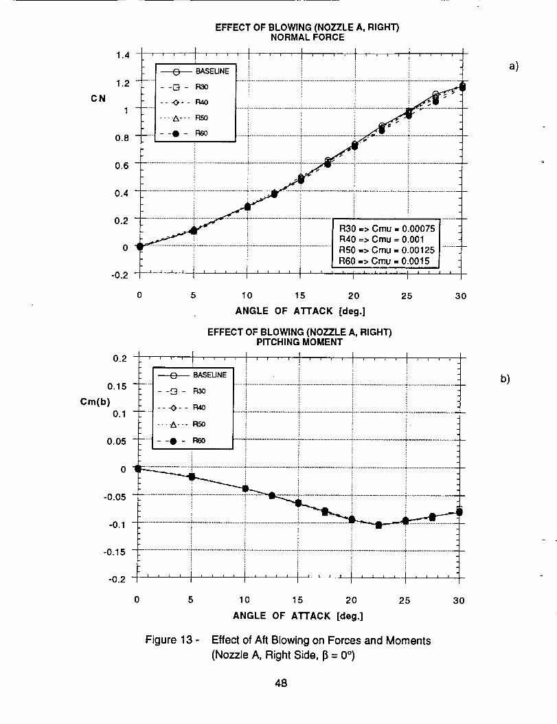
CN
1.4
1.2
0.8
0.6
0.4
0.2
-0.2
EFFECT OF BLOWING (NOZZLE A, RIGHT)NORMAL FORCE
J It .... t ....
|
R30 => Cmu = 0.00075 iR40 => Cmu = 0.001 IRS0 => Cmu = 0.00125 .........R60 => Cmu = 0.0015
I I l I JL L • I l ! I I
0 5 10 15 20 25 30
ANGLE OF ATTACK [deg.]
EFFECT OF BLOWING (NOZZLE A, RIGHT)PITCHING MOMENT
o2. .... I .... I .... I ........ t .... •BASEUNE i :: !
........... }.............................. ,........................................................... , ...........................
--[3- R30
.... ---_- - R40
----A.-- RS0
0.05 ..... I--O- 96o ............................................................................................................................|
01 - -
-0.05 -
i
-0.1 - _
-0.15 ..........................................................
-o2 '''' i ............ ' 1'''' I''''
0.15 -
Cm(b)0.1 -
0 5 10 15 20 25 30
ANGLE OF ATTACK [deg.]
Figure 13 - Effect of Aft Blowing on Forces and Moments
(Nozzle A, Right Side, I] = 0 °)
a)
b)
48

0.16
0.12 -
Cn(b)
0.08 -
EFFECT OF BLOWING (NOZZLE A, RIGHT)YAWING MOMENT
.... I ........ t .... I .... t ....-----E)_BASEUNE
--D- R30
-- -O-- R40
----A--- RSO
R30 => Cmu = 0.00075
R40 => Cmu = 0.001
RS0 => Cmu = 0.00125
R60 => Cmu = 0.0015
--Q- R6O
................................................................................................................................................................. _ .,t..a.._.. °
004 i ii i . ./-_ _ _':,_" _.."
0 4 ......... r ....................................................................... ","_; .........................
-0.04 .....................................................................................................................................................- ............................
E
008 I | I L ......... i i x 1 . , , i , i i i n I= ,
0 5 10 15 20 25 30
ANGLE OF ATTACK [deg.]
Cl(b)
0.16
0.12 -
0.08 -
EFFECT OF BLOWING (NOZZLE A, RIGHT)ROLLING MOMENT
T'"_ ; I ' I i I ' I -n _ ; •
BASEUNE
--G- R3o
---_- - R40
----A--- R50
--O- Pro0
II _ i I I t I l l • | I I
q
0.04 ..................................................................................................................................................................................:
........ ram"
0 04 .................................................................................................................................................................................
: !
w
I | I I I I I I I 1 , , , , , , , , , , = I , , , ,-0.08 w I
0 5 10 15 20 25 30
ANGLE OF ATTACK [deg.]
c)
d)
Figure 13- Continued
49

cy(b)
0.2
0.15 ......
.
i.
EFFECT OF BLOWING (NOZZLE A, RIGHT)SIDE FORCE
_BASEUNE
- -D - R30
---O-- R40
R30 => Cmu = 0.00075R40 => Cmu = 0.001
R50 => Cmu = 0.00125
R60 => Cmu = 0.0015I ............
0.1 ...... - -A--- RS0 ......".......................................................................................................................
o.... .................................:.......... ::o _ --_: ...........................i.............................i..........
!1
-o.o5 ............................i..........................................................................................._.........................................................ii
, , , , I ...... , , L I l l J , I _ , , , I , , , ,_Ou 1 I I I I
0 5 10 15 20 25 30
ANGLE OF ATTACK [deg.]
0.16
0.12 -
ACy(b)
0.08 -
0.04 -
o-t
EFFECT OF BLOWING (NOZZLE A, RIGHT)SIDEFORCE INCREMENT
• . I 1 I_.1t_ DELTAR_
I- -D - DELTAF_!!
-'1 " - "_ - - DELTARSOI
--| ----A--- DELTARC_
' i ._'.
-0.04 ...............................................................................................................................................................................
-0.08 .................................................................................................................................................................................
-0.12 .......................................................................................................................;.............................- ............................
..... ,,, ,,,, _,,,, ,,,, i ....-016. I I
..... ':" .......................................................................................... .:- ............................
0 5 10 15 20 25 30
ANGLE OF ATTACK [deg.]
e)
f)
Figure 13- Continued
5O

EFFECT OF BLOWING (NOZZLE A, RIGHT)YAWING MOMENT INCREMENT
0 08 I1
i
. i
DELTA R30
--D- DELTAR40
- - --O - - DELTA RSO
0.02 ..................................................................... :..........................................................
o I __.-,,.,:_:,-_---:-:.--_-..'_ ......................
-o.o2............................i..............................[.............................]..............................i.......................:,a-;-.-"_- ,
-0.04 ............................:......................................................................................................................................................
-o.oo............................i...........................................................].........................................................................................i :,,,,_ .... J .... J ..... , , , j____....
- 008. t I I I
0.06 -
A Cn(b)0.04 -
T_I i11_'i,ii'iiil'
0 5 10 15 20 25 30
ANGLE OF ATTACK [deg.]
ACl(b)
0.08
0.06 ......
0.04 ......
0.02 -
DELTA R30
--[3- DELTAR40
- - -_ - - DELTA R50
----A- -- DELTA R60
EFFECT OF BLOWING (NOZZLE A, RIGHT)ROLLING MOMENT INCREMENT
I I
i
"-."t, ............................................................ • .................... , ........ * ............................
............................................................................................. = ............................
-0.02 ..............................................................................................................................................................................
-0.04 ............................'....................................................................................................................................................
-0.06 ...................................................................................................................................................:_............................{
: i' ' ' ' ! ............ I .... I0 08- • I I I
0 5 10 15 20 25 30
ANGLE OF ATTACK [deg.]
Figure 13- Concluded
g)
h)
51

EFFECT OF BLOWING (NOZZLE A, BOTH)YAWING MOMENT
016. .... I .... I ........ l .... I ...., !
BASEUNEB30 => Cmu = 0.00075 I
I
B40 => Cmu ,, 0.001 I ................ E3- 133o ......................................................B50 => Cmu = 0.00125 °!
- - _- - 134o B60 => Cmu = 0.0015 I
........ -A--- EO ...................................................................i.............................+...........................
--0- BOO _ :
............................ •,............................. .:............................................................. _............................. + .......... _._ ....004 _ ! _ ti i i ,,i ! / ..
0 " _ " "_'""_ ..... "
-0.04 ................................................................................................................................................................................
__ __J._ • I I I i I l [ I l I I I • I = i ] l l I I I I-0.08 i
0.12 -
Cn(b)
0.08 -
Ci(b)
0.16
O.12 -
0.08 -
0 5 10 15 20 25 30
ANGLE OF ATTACK [deg.]
EFFECT OF BLOWING (NO77LE A, BOTH)ROLLING MOMENT
.... I ........ t ........I _ BASEUNE
.... _ - -I_ - 1330
---O-- IMO
---A--- !_
I• --O- BOOs
0.04 ...............................................................................................................................................t ............................
i G - -o : -¢
-0.04 .......................................................................................................................;...........................................................i i :
I I I
0 5 10 15 20 25 30
ANGLE OF ATTACK [deg.]
Figure 14 - Effect of Aft Blowing on Forces and Moments
(Nozzle A, Both Sides, I_= 0 °)
a)
b)
52

EFFECT OF BLOWING (NOZZLE A, BOTH)SIDE FORCE
J l t02. .... I .... _ ' ' _ - i , , , I ........
BASEUNE B30 > Cmu = 0.00075 I
.... - -D - 133o ...................................................B40 => Cmu = 0.001 !.............B50 => Cmu = 0.00125
-- -,3- - 94o B60 --> Cmu = 0.0015
0.1 ..... ....A-.. B6O ..............................................................................................................................
--t- 196o
0.05 _--0
-0.05 ............................ i....................................................................................................................................................
i i I i i , i i , . = , , , I , , , , I , i , = . _ J l t_Oe I I I I
0.15 -
Cy(b)
0 5 10 15 20 25 30
ANGLE OF ATTACK [deg.]
0.16
0.12 -
_' Cy(b)0.08 -
DELTA B30
- -[] - DELTAB40
- - -_ - - DELTA BSO
EFFECT OF BLOWING (NOZZLE A, BOTH)SIDEFORCE INCREMENT
.... .... .... I .... t ....II
q
: i
0.04 ---' ----A--- DELTA B60 ............................................................. 7"""t ............................. ".............................
= __ ! _;......0 "_ _- - -- _ ..... ".................................................. :'_":':';'5" . -....."':""-";:':':
............................_.............................._............................;...................._ ..e-.-...-....-...e..............d....'...l ..........i
-0.04 i i ; - F-'I- "_ .................I_
.o.o _i..................................................... i iii iii ii iiii iii ii i i iii iiiiii ii , -0.12
-0.16 ' ' ' ' ' ' ' ' ' ''' i, ...... ....
0 5 10 15 20 25 30
ANGLE OF ATTACK [deg.]
c)
d)
Figure 14- Continued
53

008
0.06 ......
A Cn(b) i0.04 ......
EFFECT OF BLOWING (NOZZLE A, BOTH)YAWING MOMENT INCREMENT
.... t ........ I ........i
DELTAB30
- -[] - DELTA1340
-O - - DELTAB50
t °_0.02 -Z_- DELTAB60 i
: _ i A
.......... i ................... ._ " - _-/ ' , .''.........................................................................................................: ! ! :
-0.04 ..........................:..........................................................................................._.............i : E : : ,
-0.08
0 5 10 15 20 25 30
ANGLE OF ATTACK [deg.]
0.08
0.06 -
A Cl(b)0.04 -
EFFECT OF BLOWING (NOZZLE A, BOTH)ROLLING MOMENT INCREMENT
• I I I I t I r
DELTAB30 i.... ..°.._. .............................. • .............................. i ...........................................................
- -[] - DELTAB40
.... i
- - -O - - DELTABS0 i
o.....0 | --" ,_ ........ : _.-_ "......;":_":':':'i-.'-":"
-0.04 ....................................................................................................................':..........................................................
-0.06 ...............................................................................................................................................................................i i i
008 i i .... i , i ...." " I I
0 5 10 15 20
ANGLE OF ATTACK [deg.]
25 30
Figure 14- Concluded
e)
f)
54

0.16
0.12 -
Cn(b)
0.08 -
EFFECT OF BLOWING (NOZZLE A, LEFT, NO TAIL)YAWING MOMENT
.... I .... ....... -,I .... I ....i
--_ BASEUNE
......... 13- 1.30
-- -_-- L40
...... ---_--- L50
--0- I_60
L30 => Cmu = 0.00075
.................................................L40 => Cmu = 0.001L50 => Cmu = 0.00125L60 => Cmu = 0.0015
°04 .......................................................................................................................................................................
o .... .-0.04 ........................................................._...................................................................................................i "':_
0 08 ........ I , , , l , ...........
0.16
0.12 -
Cl(b)
0.08 -
-0.04 -
-0.08
0 5 10 15 20 25 30
ANGLE OF ATTACK [deg.]
EFFECT OF BLOWING (NOZZLE A, LEFT, NO TAIL)ROLLING MOMENT
I .....i i i i i i i i i i i 1 i i i i i i _ 1
BASEUNE
.....I--G- 1.30
, -- -<)-- L4O
..... i
----A--- LSO
--t- 1.60
.04 ....................................................................................... ....................................................... ...........................
t
o: _ =
'''' '''' '''' ''''t'''' ''''1
0 5 10 15 20 25 30
ANGLE OF ATTACK [deg.]
a)
b)
Figure 15 - Effect of Aft Blowing on Forces and Moments (No Tail)
(Nozzle A, Left Side, _ = 0 °)
55

0.2
0.15 -
Cy(b)
0.1 --
EFFECT OF BLOWING (NOZZLE A, LEFT, NO TAIL)SIDE FORCE
• t 1 II i i _ i i J i t _ i i i i i i i i i i
T
BASEUNE
--D- 1_30
-- -_- - L40
----_--- t.50
--O- 1.60
L30 => Cmu = 0.00075
............................................L40 => Cmu = 0.001 .:..............L50 => Cmu = 0.00125L60 => Cmu = 0.0015
i
o.o_.......................................................T............................i............................._.........................i...................._;
-0.05 ............................ !...............................................................................................................................................
-Ol ''' '1 .... I ...... ,, I ..... ,,,$
1
0.16
Cy(b)0"120.08 I
0 5 10 15 20 25 30
ANGLE OF ATTACK [deg.]
Figure 15- Concluded
EFFECT OF BLOWING (NOZZLE A, NO TAIL)SIDE FORCE
........i....! i i............iI ---e--_ BASEUNE--El- 1.50
....' -- _-- _ .....;.............................i...................................................................................-1-
o:.c :o.oo, iiiiiiii IR50 => Cmu = 0.00125
BS0 => Cmu = 0.00125
i
I 1
0.04 -
o |
-0.04 -
-0.08 -
-0.12 .........................................................;............................................: .=
-o.16 '''' '''' i'''' I'''' I''''''
0 5 10 15 20 25 30
ANGLE OF ATTACK [deg.]
Figure 16 - Effect of Aft Blowing on Forces and Moments (No Tail)
(Nozzle A; Left, Right and Both Sides; J_= 0°)
c)
a)
56

EFFECT OF BLOWING (NOZZLE A, NO TAIL)YAWING MOMENT
0.16 .... I .... • , r , , • .... - .... • _---T --i
BASEUNE
....... [2- 1.50
---O-- FLS0
0.08 ......i'"_ BSO ................................................................_........................................................
i
0.04 ............................"............................"............................_.............................._,_i....................................................
o i ....T
-o.o4T i i i i i a.
-0.08 j j _ I '
0.12 -
Cn(b)
0 5 10 15 20 25 30
ANGLE OF ATTACK [deg.]
b)
EFFECT OF BLOWING (NOZZLE A, NO TAIL)ROLLING MOMENT
016. ! .... I ........ ' ...... _ ,", , ,
BASELINE
--'_- - R50
0.08 .......... -A--- BSO .........................................................................................................................
0.04 ............................................................................................................................................................................
o -i _ -_-_
-0.04 ...................................................................................................................
I [ I ! i , l I I I I I I | I I I i I 1 I I i I I-0.08 i
0.12 -
Cl(b)
0 5 10 15 20 25 30
ANGLE OF ATTACK [deg.]
c)
Figure 16- Concluded
57

0.16
0.12 ......
C n(b)
o.o8 ..... -.-.A-.- L_
--El- I_m
0.04 ...........
EFFECT OF BLOWING (NOZZLE A, LEFT, BETA = 5 °)YAWING MOMENT
• I I I t IBASEUNE ;
: _ L30 => Cmu = 0.00075i
- -[3 - 1.3o .......; ............................._................ L40 => Cmu = 0.001L50 => Cmu = 0.00125
- - _- - 1.4o L60 => Cmu = 0.0015...........
.__................: , _-';"_" _ _-_;_l
-o.o_ .........................................................................................-_-_:-:,...................._..........................t"0.08 I z [ , i z I , l _ I J , I I I J _ , , 1 .... 1
I I
0 5 10 15 20 25 30
ANGLE OF ATTACK [deg.]
EFFECT OF BLOWING (NOZZLE A, LEFT, BETA = 5 °)ROLLING MOMENT
0.16 .... I ....................
• v'_ BASEUNE
....i--[3- 1.30 ......, ....................................................................................................................
i---_-- 1.4oi
0.08 ..... i ""'_"" I.E) ..........................................................................................................................
I --i leot
0.04 ..................................................................................................................................................................................
0 4
...........................i..............................i...................................................................................rj
0.12 -
Cl(b)
-0.04 -
-0.08
0 5 10 15 20 25 30
ANGLE OF ATTACK [deg.]
Figure 17 - Effect of Aft Blowing on Forces and Moments
(Nozzle A, Left and Right Sides, _ = 5°)
a)
b)
58

02
016 -
Cy(b)012 -
008 -
0.04 -
i
EFFECT OF BLOWING (NOZZLE A, LE_, BETA = 5°)SIDE FORCE
_1tll i#11 ill| illl ii#J
=
BASEUNE
--i--4- I..30
--K)- - L40
-..oleo..I..._0
--I- LeO....................................i.........................................................................................
E
0 --
-0,08 -
-012, , , , i , , , J i , , , ,
I 1 1 i
Cy(b)
016
0.12 .....
0.08 .....
0.04 ......
5 10 15 20 25
ANGLE OF ATTACK [deg.]
EFFECT OF BLOWING (NOZZLE A, RIGHT, BETA = 5 °)SIDE FORCE
I ....., , i i _ _ i i i i t i s I i i i i i
BASEUNE
--[3- R30
---O-- R40
- A- - R._
3O
! .-0-0 --0- R60 • ........................................... ;............................................. :....... ......... .;.......... ................... _-
! _ • _." " 1'4._
!_____..._.....i.............................o.o iiiiiii iiiiiii!ii!ii;i; .i ii -o.12............................!.............................!...........................................................i............................._............................
: } :
.... i .... i ........ i .... i ....-0.16 _ I i J
0 5 10 15 20 25 30
ANGLE OF ATTACK [deg.]
c)
d)
Figure 17- Continued
59

EFFECT OF BLOWING (NOZZLE A, RIGHT, BETA - 5°)YAWING MOMENT
l '0.16 .... t .... " .... ' .... I .... t .... '
+ BASEUNE R30 => Cmu = 0.00075 IR40 => Cmu = 0.001 !0.12 - -[3 - R3O R50 => Cmu = 0.00125
Cn(b) -- -O- - R4O R60 => Cmu = 0.0015
0.08 ----Z_--- RSo ..............................................................................................................................
......;................'............................i...........................,..........................lo.........................i .... _:"5__2_:::A-..... '_,-::::-÷2 .................i- -i i -_-.. ................ ""
-0.04
-o.o8 , .... ,' .... '''' t'''' 1'''' t''''
0 5 10 15 20 25 30
ANGLE OF ATTACK [deg.]
0.16
0.12 -
Cl(b)
0.08 -
0.04 -
0 4
-0.04 -
-0.08
EFFECT OF BLOWING (NOZZLE A, RIGHT, BETA = 5°)ROLLING MOMENT
.... I .... I .... 1 ........ ....BASEUNE
,
,--[3- R30
--.-_-- R40
----A--- R50-0- F_
....................................................._...:....._...2..:..i....:.;:_:.:_.<_:. ..................................................
_i ! - - _:.c . -j _......
.... l,,,,I,,,,l,,,,I,,,,I ....I
0 5 10 15 20 25 30
ANGLE OF ATTACK [deg.]
e)
f)
Figure 17- Concluded
60

0.16
0.12 -
Cn(b)
0.08 -
EFFECT OF BLOWING (NOZZLE A, LEFT, BETA = -5 °)YAWING MOMENT
I t II i i i i i i i • i i i i i t r T r i i i r i I i
BASEUNE
--D- 1.30
-- "_3- - L40
-..._--- i.50
L30 => Cmu = 0.00075
.................................................L40 => Cmu = 0.001
L50 => Cmu = 0.00125
L60 => Cmu = 0.0015
i ,;.LJ...-'_ .-" .L "_--.,. _,.-,f_
-0.04 ...................................................................................................................................................................................
........ I ''''l ........ I''''-0.08 i
0 5 10 15 20 25 30
ANGLE OF ATTACK [dog.]
0.16
0.12 -
Cl(b)
0.08 -
0.04
0 t
EFFECT OF BLOWING (NOZZLE A, LEFT, BETA = -5 °ROLLING MOMENT
. _ , i i i i i ; ; _ i i i i i i i _ • l 1 _ i i '
BASEUNE
--D- 1.30
i!
---_-- 1.40
.... A _o .......i.............................i..............................i.............................T..........................--.- _ .......i.............................i............................i.........................__
...._ -- i ! i _":i .........
........i............................
i
I t i I I I I I
0 04 ......................................................................................................................
0 08 ........ I ..........- . l
0 5 10 15 20 25 30
ANGLE OF ATTACK [deg.]
Figure 18 - Effect of Aft Blowing on Forces and Moments
(Nozzle A, Left and Right Sides, I] = -5°)
a)
b)
61
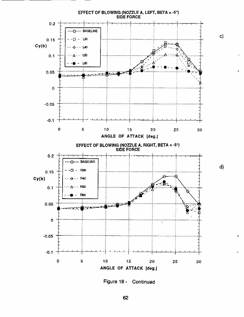
0.2
0.15
Cy(b)
0.1
0.05
-0.05
-0.1
EFFECT OF BLOWING (NOZZLE A, LEFT, BETA = -5°)SIDE FORCE
I I 1 I t I I I l .
0 5 10 15 20 25 30
ANGLE OF ATTACK [deg.]
EFFECT OF BLOWING (NOZZLE A, RIGHT, BETA = -5°)SIDE FORCE
..............................................................................................Cy(b) ' -- -O-- R4o i ! _
0.1
0
-0.05
-0.1 1 t I I = I I I I I I I I 1 t I i = I I I I I I
I
0 5 10 15 20 25 30
ANGLE OF ATTACK [deg.]
c)
d)
Figure 18- Continued
62

0.16 _'. ' ' ' IBASEUNE
0.12 " --[-4- R3o
Cn(b) -- -O-- P,4o
0.08 .....-.--A--- RSO
0.04 -
Ol
EFFECT OF BLOWING (NOZZLE A, RIGHT, BETA = -5 °)YAWING MOMENT
I _ I III_tltl ,11
R30 => Cmu = 0.00075
...............................................R40 => Cmu = 0.001 ................
R50 => Cmu = 0.00125
R60 => Cmu = 0.0015
4,
--0- _ '-. i ,""
- ._
-0.04 ..............................................................................................................................................................................
, , [ , ! , J , i I I J 2 s . z i , J . , z z x _ [ , ii0108 I
0 5 10 15 20 25 30
ANGLE OF ATTACK [deg.]
EFFECT OF BLOWING (NOZZLE A, RIGHT, BETA = -5 °)ROLLING MOMENT
016. .... I ..... -, , , ' .... " .... I .... m
t i
BASEUNE i
- -D - R30 ....................................................................................................:............................
---O- - R40
----A-- - I:LSOo
--0- Rso_ ..__._,
.... ..'..._...'....._ .............................................................................................................. . :..........O. 04! -Z
_, ........ _ _ -__,.o_i _0 • .................. -;7,..................................................................._ .......................................................
............................ i .............................. t ............................. t ........................................................................................
-0.04 i i
-o.o8 '''' i'''' I'''' I'''' '''' ''''
0.12 -
Cl(b)
0.08 -
0 5 10 15 20 25 30
ANGLE OF ATTACK [deg.]
e)
f)
Figure 18- Concluded
63

0.16 l ....
BASEUNE
0.12 --[2- L3O
Cn(b)---<)--I.4o
0.08
0.04
-0.04
-0.08
EFFECT OF BLOWING (NOZZLE A, LEFT, BETA = -10 °)YAWING MOMENT
' I l J ll | i i f i i i J i i i _ J t _ i r i _ i
..........i.............................i............!i
L30 => Cmu = 0.00075 |
L40 => Cmu = 0.001 !..............LS0 => Cmu = 0.00125L60 => Cmu = 0.0t 15
u _
--O- Ie0 _,.'q......................................................... -,............................. :.............................. ;.................... ; ........................ _f ,1_
0
...........................!.............................i..........................................................................................i...........................I I U I _1 t ] I I I I J I I I A I i _ z I I I I_ t I l
5 10 15 20 25 30
ANGLE OF ATTACK [deg.]
EFFECT OF BLOWING (NOZZLE A, LEFT, BETA = -10 °)ROLLING MOMENT
0.16 .... I .... /
BASEUNE : i
- --[2- 1.3o ...............................................................................................................................
---_-- LAO
0.08 ............ :.............................;........................................................._.-.'....-."._,,..........
----A---IS) i i ! ,__
0.04 _ _ .........._..........................._........:"t',:_ .............;_.: i-
0 -i ..............................................................................................................................
-0.04 ........................................................................................................................................
i i i i i ......................."0.08 _ _J I , , I i I 1 i i , t I i , , I , 1 I I I I L lI 1 I
0 5 10 15 20 25 30
ANGLE OF ATTACK [deg.]
Figure 19 - Effect of Aft Blowing on Forces and Moments
(Nozzle A, Left and Right Sides, 13= -10 °)
0.12
Cl(b)
b)
a)
64

Cy(b)
Cy(b)
0.2
0.15
0.1
0.05
_ _
-0.05 - -
-0ol
EFFECT OF BLOWING (NOZZLE A, LEFT, BETA = -10 °)SIDE FORCE
l ... I .... +.... I .... I ........
•_..-._+-_-__i_-,--:.----e------_--':
__ _, _,
_. -
--[3- L_ •
0.2
0.15
0.1
0.05
0
-0.05
-0.1
---_-- 1.40
....A-.. LS0
-0- LeO
i i [ i
I
] i [ t i I I [ ! 1 i t i I _ ! _ 1 1 1 [ I I
l I I
0 5 10 15 20 25 30
ANGLE OF ATTACK [deg.]
EFFECT OF BLOWING (NOZZLE A, RIGHT, BETA = -10 °)SIDE FORCE
, . . . .i i i i i l • t i i i i i i i J r i i i i i _ i
: ; _ Q_. _ --_all-.... _ _--- _,+
.... ..............................?..........._ ................,_ ......._-............_ ...........
...........................i.............................i..............................i.....................--[3- P,30
---_- - R40
--. -A--. P,50
--0- R60
I I A I i I t l I
1
.................................................................................................. T ............................
+t J I I t I E I I + I l I I I I I
I
I
0 5 10 15 20 25 30
ANGLE OF ATTACK [deg.]
c)
d)
Figure 19- Continued
65

EFFECT OF BLOWING (NOZZLE A, RIGHT, BETA = -10 °)YAWING MOMENT
o16 .... I .... .... I .... I .... I ....i
BASEUNE: R30 => Cmu = 0.00075
.... - -E3 - R30 ...................................._.............. R40 => Cmu = 0.001: R50 => Cmu = 0.00125
- - -o- - _ -: R60 => Cmu = 0.0015
i--I- 96o i i .
J i _B
............................:............................_.....................................................................................................#.--:- :.O.04i i
i i - -i_ _...._ .-._:;-• i i : "i----.--_ .
-0.04 ...........................i............................................................-........................................................................................
008 ''''I''''I''''I'''' ''' .....
0.12 -
Cn(b)
0.08 -
0 5 10 15 20 25 30
ANGLE OF ATTACK [deg.]
EFFECT OF BLOWING (NOZZLE A, RIGHT, BETA = -10 °)ROLLING MOMENT
016. .... I .... ' .... ' ............
BASEUNE
..... --[3- R30
---O- - R40
....i-. _-.- _ .....:.............................i..............................!..................i .........................--i i i ,< "o li i
Ot i ..........................................:'-.......
0 04 ..................................................................................................................................................................................." ° :: i
008 ..... '''''''''I''''I' ..... ''
0.12 -
Cl(b)
0.08 -
0 5 10 15 20 25 30
ANGLE OF ATTACK [deg.]
Figure 19- Concluded
e)
f)
66

0.16
0.12 -
Cn(b)
0.08 -
EFFECT OF BLOWING (NOZZLE B, 30 ° IN, LEFT)YAWING MOMENT
.... I .... I ....... - I .... I ....BASEUNE
--[]- 1.30
--._3-- 1_4o
----A--- t._
--I- I..60
L30 => Cmu = 0.00075
.............................................L40 => Cmu = 0.001L50 => Cmu = 0.00125L60 => Cmu = 0.0015
0.04 ........................................................................................._........................................................................................
.... _r .............................................i-..........................._...........................
..........................,............................._.............................!..........................-.=-.:......................._......."._-,::..iE i
I I I I 1 I I 1 I t I I J 1 i I i I , L l I I I I I i 1
I I I
-0.04 -
-0.08
0 5 10 15 20 25 30
ANGLE OF ATTACK [deg.]
EFFECT OF BLOWING (NOZZLE B, 30 ° IN, LEFT)ROLLING MOMENT
016. .... I .... " .... • ' _--_ , _ _ _ - , , ,_
_ BASEUNE
Ii---O-- L40I
0.08 ..... t ----A--- L.So ...........................................................................................................................
i
I --0 LeO
0.04 "- ..................................................................................................................................................................................
o
•_ i
-0.04 .................................................................................................................................................; ..........................
F :i0908 I i I
0.12 -
Cl(b)
0 5 10 15 20 25 30
ANGLE OF ATTACK [deg.]
Figure 20 - Effect of Aft Blowing on Forces and Moments
(Nozzle B301N, Left and Right Sides, 13= 0 °)
a)
- B301N
-- I32C m
.
b)
67
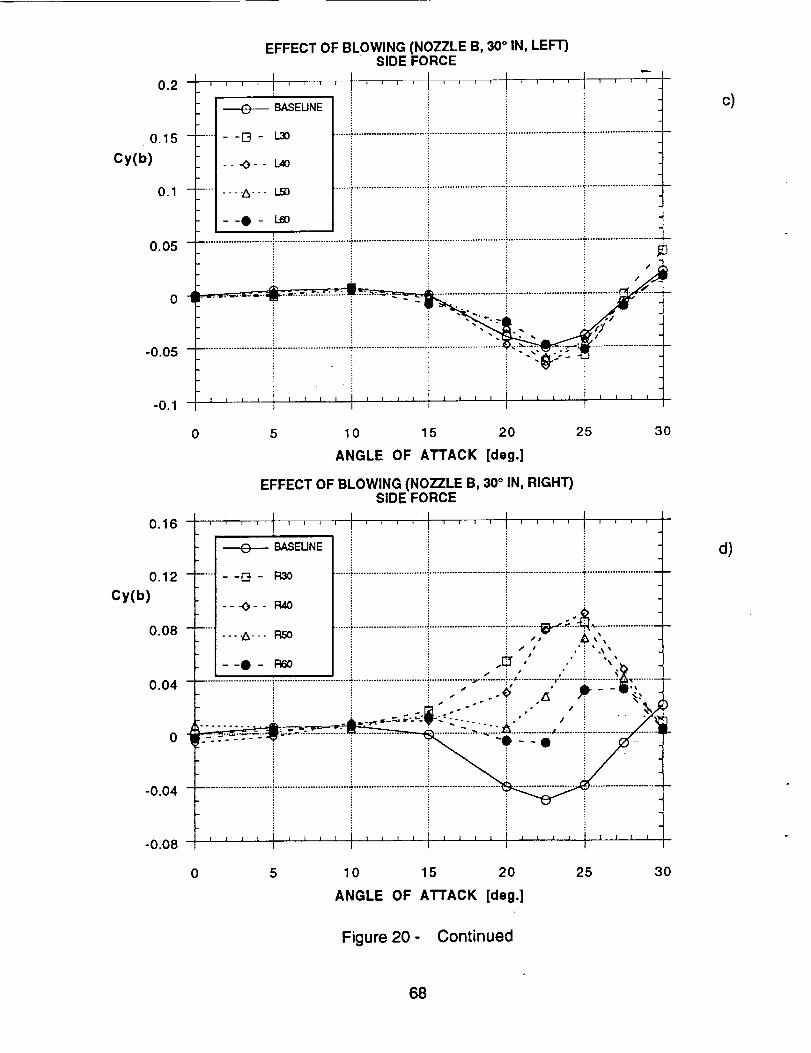
0.2
0.15 -
Cy(b)
0,1 --
0.05 -
o-I
-0.05 -
-0.1
0.16
0.12 -
Cy(b)
0.08 -
0.04 -
-0.04 -
-0.08
EFFECT OF BLOWING (NOZZLE B, 30° IN, LEFT)SiDE FORCE
_BASEUNE
--D- 1.30
---0-- 1.40
..._--- LSO
--0- 1_60
/
] I II
5 10 15 20 25 3O
ANGLE OF ATTACK [deg.]
EFFECT OF BLOWING (NOZZLE B, 30° IN, RIGHT)SIDE FORCE
,l ,,,I ........ .... ....BASEUNE
..... --D.- R3O .......':.......................................................................................................................
-- -o- - mo ................................................................................_.__._._,---.A-.- RSO ,,, ,&_,
,_ U • •
• • 4 •
--O- 96o .,_ ,, .. ,._>iii i J ; • &
= i _ ,, ,k" ' dL- - -_', -]--
.......... : .- --_"-="':"-v" :....... : ." , i /
.- ._ ............ :............-.........;.:._ ................_..........;.................,, ......-=_
1 I
0 5 10 15 20 25 30
ANGLE OF ATTACK [deg.]
c)
d)
Figure 20- Continued
68

0.16
EFFECT OF BLOWING (NOZZLE B, 30 ° IN, RIGHT)tAWING MOMENT
I ' l t -BASEUNE
R30 => Cmu = 0.00075.....................................................R40 => Cmu = 0.001
RS0 => Cmu = 0.00125R60 => Cmu = 0.0015
0.12 _ ..... [3- R3o
Cn(b) -- -O- - 1:14o
0.08 ........ A-- _ .............................................................................................................................--._ _ Zi_m i
0.04........- -..,.--.......................:.............................:..............................:.............................:............E,_J_i i ,, -_ - i . ,;'_
ii . .
o.• _ " _ v ..... _"--'_'_':";:_";:."'" ............. :".":'"-":':'" "-'; .......................
"0.04 .................................................................................................................................................................................)-
" " I
0 5 10 15 20 25 30
ANGLE OF ATTACK [deg.]
EFFECT OF BLOWING (NOZZLE B, 30 ° IN, RIGHT)ROLLING MOMENT
016. .... 1 .... ........ ' ,', ...... --
I ---e-- BASEUNE
....1--O- R30
---O-- R40
0.08 ...... ----Z3- - - P,SO ..........................................................................................................................I
....!:;' '_ , loo, i ......................i.....................................................................
I • ¢-- ::?.::---:-._,::.._.:._.... _..r....!;. ......................
0 04 ...........................................................- , :
-o.o8 '''' I'''' '''' I'''' t, .... t''''
0.12 -
Cl(b)
0 5 10 15 20 25 30
ANGLE OF ATTACK [deg.]
e)
f)
Figure 20- Concluded
69

0.16 f '
0.12 ....
Cn(b)
0.08 .....
I
BASEUNE
--D- L30
-- -_-- L40
----A-.. L_
--0- LeO
EFFECT OF BLOWING (NOZZLE B, 30 ° OUT, LEFT)YAWING MOMENT
t t t
L30 => Cmu = 0.00075..................................................L40 => Cmu = 0.001
L50 => Cmu = 0.00125L60 => Cmu = 00015
.04 .................................................................................................................................................................................
..-" ..':--:-'-_- -b----_-... j"---"--"--" _" :""'" ..... . i x,.. ......... "- . -
0 " ................... _ _ ,._ _ _ -.
-0.04 .................................................................................................................................................................................
I I [ I _ I [ I . I 1 l I I I I I J I 1 l I | I I I
-0.08 i
0 5 10 15 20 25 30
ANGLE OF ATTACK [deg.]
EFFECT OF BLOWING (NOZZLE B, 30 ° OUT, LEFT)ROLLING MOMENT
016. .... t ....................
_ BASEUNE
....l--G- L3O .......................................................................................................................II---O-- 1.40
0.08 ..... ] --0""-A--- tnot'SO .............................................................................................................................
0.04 ............................................................................................................................................................................
. .°
-0.04 i
E!
008 .... i ...... .... '1 ....- o
0.12 -
Cl(b)
0 5 10 15 20 25 30
ANGLE OF ATTACK [deg.]
Figure 21 - Effect of Aft Blowing on Forces and Moments
(Nozzle B30OUT, Left and Right Sides, I_ = 0 °)
a)
B30OUT
b)
7O
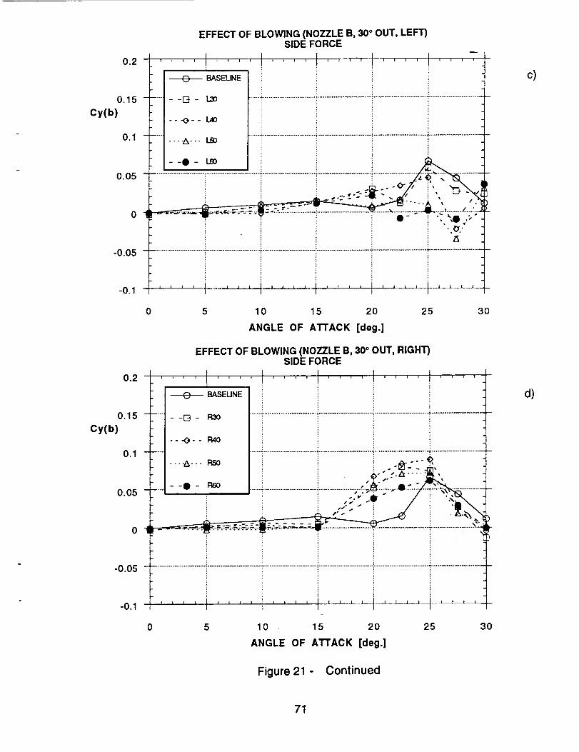
0.2
0.15 -
Cy(b)
0.1 --
0.05 -
ol
-0.05 -
-0.1
0.2
0.15
Cy(b)
0.1
0.05
0
-0.05
-0.1
EFFECT OF BLOWING (NOZZLE B, 30 ° OUT, LEFT)SIDE FORCE
.... I ........ 1 , , ,'_, ........i
]- I _ BASEUNE"' - -D- L3O ....................................._........................................................................................
I---._-- 1.4o
.... -Z_--- I..50
.... ....................................................................................................-I• - .. _Q ,;
5 10 15 20 25 30
ANGLE OF ATTACK [deg.]
EFFECT OF BLOWING (NOZZLE B, 30° OUT, RIGHT)SIDE FORCE
__. I I L_--
10 15 20
ANGLE OF ATTACK [deg.]
25 3O
Figure 21 - Continued
c)
d)
71

0.16 t
012 .....
Cn(b)
0.08 .....
EFFECT OF BLOWING (NOZZLE B, 30 ° OUT, RIGHT)YAWING MOMENT
t 1 ti
+BASEUNE
--D- R30
---_- - R40
_ R50
--I- Rroo
t i i t t
: R30 => Cmu = 0.00075......_..........................................R40 => Cmu = 0.001
R50 => Cmu= 0.00125R60 => Cmu = 0.0015
.................................................................. i .........................................................
.04 ...................................................................................................................... i .........................................................
; It
-0.08 l
0 5 10 15 20 25 30
ANGLE OF ATTACK [deg.]
EFFECT OF BLOWING (NOZZLE B, 30 ° OUT, RIGHT)ROLLING MOMENT
I I I0.16 ................ .., , , , ' ....; i i
+ BASEUNE i
.... - -ra - Pao ......:"............................._.........................................................................................
--_-- R40
0.08 ....................................................................................................................................----A..- RS0
--O- R600.04 ................................................................................................................................
0
-0 04 .................................................................................................................................................................................
i"008 ...... ' J ' ' I '' * '] I I I I l ] I I I I I
0.12 -
Cl(b)
0 5 10 15 20 25 30
ANGLE OF ATTACK [deg.]
Figure 21 - Concluded
f)
e)
72

0.16
0.12 ......
Cn(b)
0.08 ......
EFFECT OF BLOWING (NOZZLE C, LEFT)YAWING MOMENT
BASEUNE
--I-4- 1.30
---O-- 1_40
-...A... LS0
--0- le0
o ..........................:.......................................................................................i............-0.04
-0.08 _ i l i i I l i i [ i i I I J i . I i I i . i i i !
; ! C
L30 => Cmu = 0.00075
.....................................................L40 => Crnu = 0.001L50 > Cmu 0.00125L60 => Cmu = 0.0015
0 5 10 15 20 25 30
ANGLE OF ATTACK [deg.]
0.16
0.12 -
Cl(b)
0.08 -
0.04 ....................................................................................!............................................................i............................i i _ -G --_
o', =_____ :=_ .._..__,..._.,.-.._.-,..-...-..,Ik....-..-..__
= _ -_.....
EFFECT OF BLOWING (NOZZLE C, LEFT)ROLLING MOMENT
.... t ....... I ............BASEUNE !
---_-- L40
----A--- LS0 ...............................................................................................................................
--0- I..60
-o.o4 ............................. ! , i: i :
008 '''' .... _''''1''''t'''' ''''
0 5 10 15 20 25 30
ANGLE OF ATTACK [deg.]
Figure 22 - Effect of Forward Blowing on Forces and Moments
(Nozzle C; Left, Right and Both Sides, _ = 0 °)
a)
2 5 cm
b)
73
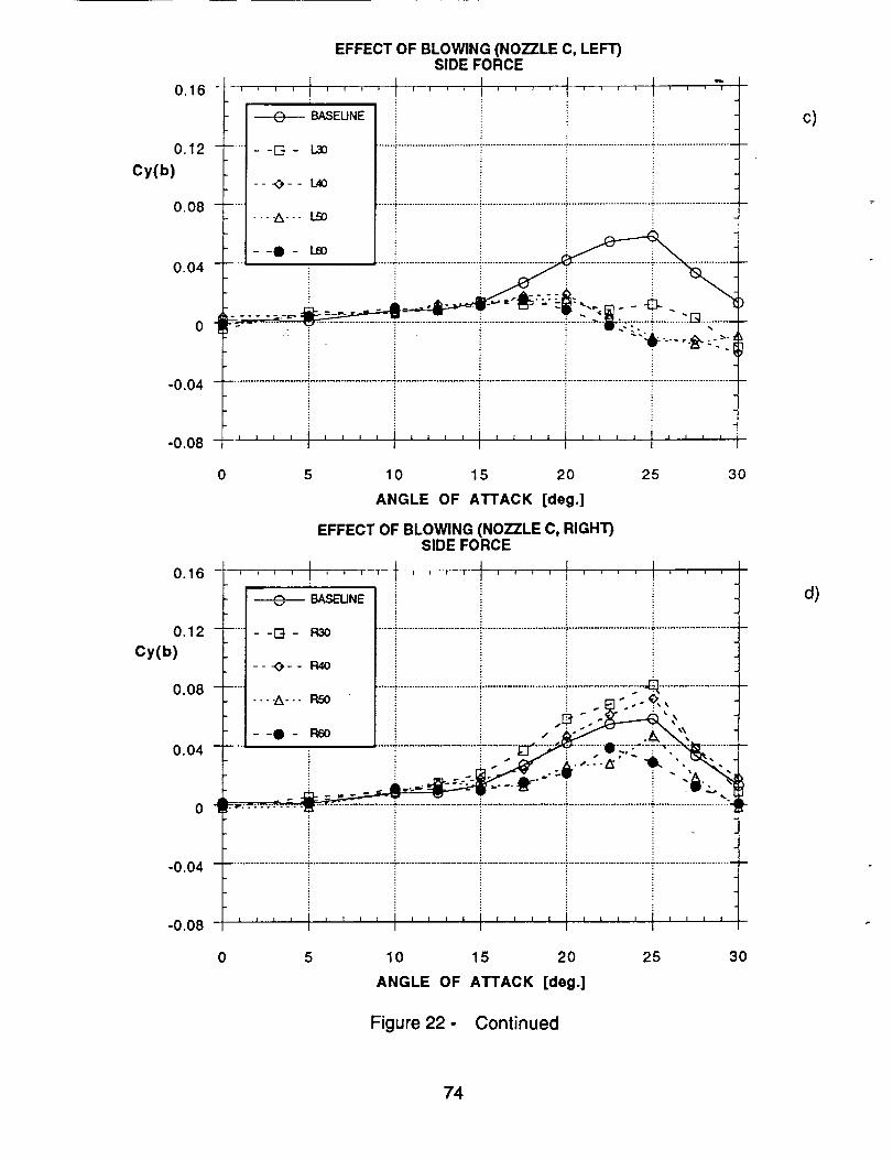
0.16 -
0.12 -
Cy(b)
0.08 -
0.04 -
o-!
EFFECT OF BLOWING (NOZZLE C, LEFT)SIDE FORCE
1 t ti i I I i i t '1 .... I l i I ' I 1 I i I I I I
n !
BASEUNE
--D- 1,30
-- -_- - L40
.,'k.. - LSO
ii
--_ .... _:_
-0.04 .....................................................................................................................................................T...........................
, , , , , , , , 1 , , , , I , , , , 1 , , L , I _ , _ _-0.08 J I t t
.....:-,,: _ ..............................._ -,c=--- ":..-.-_ll"z-- . . - _ ";1_i. i _J'a
0 5 10 15 20 25 30
ANGLE OF ATTACK [deg.]
EFFECT OF BLOWING (NOZZLE C, RIGHT)SIDE FORCE
0.16 - ' ' ' ' I .... _- ...... .........
o.o__7............._..._ i.............................i..............................i............_;;;__ .......................1 I _ _ .e .-_----a.'.," I--o- 96o I i i - J_.:.>P" ._\'\
004 ..... ' ; '_ ............................i.........; _:":-h_. .......
o ..............
-0.04 ...............................................................................................................................................................................
t 1 I t I I I I 1 I I | I | J I J l | I | I I I
-0.08
0.12 -
Cy(b)
0 5 10 15 20 25 30
ANGLE OF ATTACK [deg.]
Figure 22- Continued
c)
d)
74

0.16
0.12 -
Cn(b)
0.08 -
EFFECT OF BLOWING (NOZZLE C, RIGHT)YAWING MOMENT
i f I I ---_ BASEUNE
--O- R_
---_-- R40
----A---RS0
R30 => Cmu = 0.00075...................................................R40 => Cmu = 0.001
R50 => Cmu = 0.00125R60 => Cmu = 0.0015
--0- P,6O/
0.04 "--...........................":::..............................ii"............................."i..............................i".............................Ti............_.._r-,_-_i_""
! ii _ • _ 7, - _! i ,_- :_*o"0-I, ........ ,- ..................... _ ....................
-0.04 ........................................................................................:..........................................................................................
I I I I I I I I 1 1 l ] I I I ] ] I ] I I I I I I-0.08 j
0 5 10 15 20 25 30
ANGLE OF ATTACK [deg.]
0.16
0.12 -
Cl(b)
0.08 -
I ---e-_ BASEUNE
|
.... 1--[El- R30I
_--,-O-- R40
.... 1 ----A---_O_1:t6oR50
EFFECT OF BLOWING (NOZZLE C, RIGHT)ROLLING MOMENT
.... I ........ .... .... F-, ,,¢
I I I
0.04 ....................................................................................................................i...................................................
I qP .... I1_" .-,-_- :w:-_: .... :".T::';'" -',-It."---' .......... .i"...........................
-0.04 ...........................................................
008 .... i ...." • I
0 5 10 15 20 25 30
ANGLE OF ATTACK [deg.]
Figure 22- Continued
e)
f)
75

0.16
0.12 .....
Cn(b)
0.08 ......
EFFECT OF BLOWING (NOZZLE C, BOTH)YAWING MOMENT
I I t 1BASEUNE
--0- 133o
---O- - B4O
....A-.- BSO
--0- B6O
i
B30 => Cmu = 0.00075....................................-.............. B40 => Cmu = 0.001
B50 => Cmu = 0.00125B60 => Cmu = 0.0015
o.o4 ..........................i.............................T.............................]..............................i.............................7....................:
0
-0.04 ..................................................................................................................................................................................
z , , _ , , _ , ! ........ I .... I I I I"008 * I i
0 5 10 15 20 25 30
ANGLE OF ATTACK [deg.]
Cl(b)
0,16
0.12 -
0.08 -
EFFECT OF BLOWING (NOZZLE C, BOTH)ROLLING MOMENT
i _ 1 i I t _ i i i , i i t i i i _ = i ¢
,-_e----BASEUNE
.... t--_- 133o
t ---_3-- B,4o....... _--. Br:o
--t- I_i
o.. i i i
-0.04 ............................ i..............................i .......................................................................................................................
I I 1 I-0.08 .... i'''' i .... I,,, , t .... I ....
0 5 10 15 20 25 30
ANGLE OF ATTACK [deg.]
Figure 22- Concluded
g)
h)
76
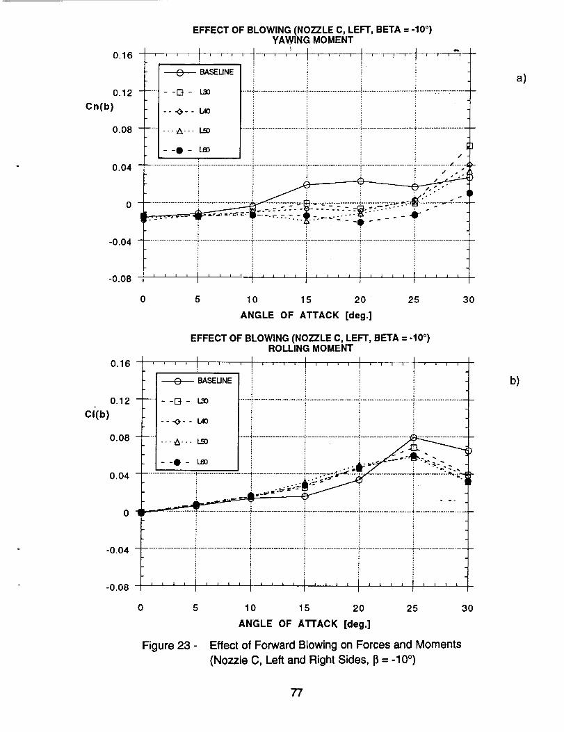
0.16
0.12
Cn(b)
0.08
0.04
-0.04
-0.08
EFFECT OF BLOWING (NOZZLE C, LEFT, BETA = -10 °)YAWING MOMENT
i ; t i i i i i ; i i t i i 1 ! i 1 i ; i ; I i
i ,
BASEUNE
--O- 1.20
---_-- 1_40
- - - -A--. 1..90
--O- leo
...... . ............................. , ....................................................................... =.+.,,.............
/
...................................................................... ,,, J- ......s
/ ,,o •
,/ -o •
/j J.-"
................................... v. ......................... *................... z._ -_--- ............. _ ..........
..........................+..........................................................................................+..........................................................I I I t
0 5 10 15 20 25 30
ANGLE OF ATTACK [deg.]
EFFECT OF BLOWING (NOZZLE C, LEFT, BETA = -10 °)ROLLING MOMENT
016. .... I .... "'=' ' ' ' . ..... m-_- , - , , , , •
I _ BASEUNE
.... - -I--Jr - L_0 ..............................................................................................................................
-- K)-- L40
o. .... ---.A-.. L_ ......7.........................i........."....................................................................
--.- L= + +0.04 .........................................................+:.............................'.................- -: _'"_"'"="_" ................................. :'_'-"'_.
01 :
-0.04 ..........................................................................................................................................................................
+ J i J.... I .... I .... I ...... I .... I ....
-0.08 i i I _ I
0.12 -
Ci(b)
0 5 10 15 20 25 30
ANGLE OF ATTACK [deg.]
Figure 23 - Effect of Forward Blowing on Forces and Moments
(Nozzle C, Left and Right Sides, 13= -10 °)
a)
b)
77

0.2
0.15 -
Cy(b)
0.1-
0.05 "
__.
-0.05 .....
-0.1
EFFECT OF BLOWING (NOZZLE C, LEFT, BETA = -10 °)SIDE FORCE
i ] _ i _ F I I r f I r I I 1 n _ r I _ I , , I
....................................................................................................................... [ ........................................................
............................................................................................. _............. _,_,_ ....................... 2:'_
_ ---_ BASEUNE i k. ,_,, [ ] ° - :._:.- -'
0,2 "
0.15
Cy(b)
0.1
0.05
_
-0.05 -
-0.1 -
0 5 10 15 20 25 30
ANGLE OF ATTACK [deg.]
EFFECT OF BLOWING (NOZZLE C, RIGHT, BETA = -10°)SIDE FORCE
_ ' ............... I .... I ............................... ° .......................................................................................... i ............................. i ..........................
"A .... ":
_ BASEUNE- -t-:t - R30
-1---O-- 1:),40
_.1.--_... FLS0
I--e- RsoI
. .°
J 1 t t I I | 1 I i J i 1I
5 10 15 20
ANGLE OF ATTACK [deg.]
25 30
Figure 23- Continued
c)
d)
78

0.16
0.12
Cn(b)
0.08
0.04
0
-0.04
-0.08
EFFECT OF BLOWING (NOZZLE C, RIGHT, BETA = -10 °)YAWING MOMENT
I ' II i t n I _ 0 I "t I = I u " 1 I I 1 " I -" -I r u I I i
BASEUNE
....... D- R30
---_- - R4O
--O-
I f I I I 1 , , I , , , i i i i I . i i i l J 1 1 i i
I I
0 5 10 15 20 25 30
ANGLE OF ATTACK [deg.]
0.16
0.12 -
Cl(b)
EFFECT OF BLOWING (NOZZLE C, RIGHT, BETA = -10 °)ROLLING MOMENT
i
_ BASEUNE
..... --[3- R30i
----_-- R40
t
0.08.....mo ......i.............................!..............................i.............................................-- -
- -e ..............................i.............................i.........................
0.04 ........................... ,i ..-.'. _."-- _-." ,.'_. :: = "
0 04 .................................................................................................................................................................................
i :
I I m
I t I ! I I I I ] ] t X I I I I I | . I I .l ,l l 1 I I -J.__-0.08 i t I
0 5 10 15 20 25 30
ANGLE OF ATTACK [deg.]
Figure 23- Concluded
e)
f)
79

0.16
0.12 -
Cn(b)
0.08 -
EFFECT OF BLOWING (NOZZLE D, LEFT)YAWING MOMENT
BASEUNE
....... [3- 1.3:)
----A--. 1.50
........ I .... t'''_'!
L30 => Cmu = 0.00075 I
.......................................................L40 => Cmu = 0.001 I .............L50 => Cmu = 0.00125L60 => Cmu = 0.0015
........................................................................;........................................................_---t- LeO i "
Jl
-0.04 ..........................................................."......................................................................................................................
008 ''''f''''t'''' ..... I''''t''''- o
0 5 10 15 20 25 30
ANGLE OF ATTACK [deg.]
EFFECT OF BLOWING (NOZZLE D, LEFT)ROLLING MOMENT
016. .... l ........ I .... . ..... ...,, ,
I_ BASEUNE
I....... [] - L30 ......,.......................................................................................................................
--_3-- L40
I........ oA--- 1._ .........................................................................................................................
I
I--Q- I._
0.04 ............ i............................................i"........................................................................................i ..................i_
_ A0 I w ,w
-0.04 ..........................................................•.......................................................................................................................
-o.o8 '''' '''' I'''' I'''' I'''' t''''
0.12 -
Cl(b)
0.08 -
0 5 10 15 20 25 30
ANGLE OF ATTACK [deg.]
Figure 24 - Effect of Forward Blowing on Forces and Moments
(Nozzle D, Left and Right Sides, 13= 0 °)
a)
D
b)
8O

Cy(b)
Cy(b)
EFFECT OF BLOWING (NOZZLE D, LEFT)SIDE FORCE
02 I • ; • -1 i i i i i I I I f I I I I I i l I 1 I l I I Ii
i |
---e-- BASEUNE
0.15 ....... [] - 130
i -- -_-- L400.1 ----A--- I.S0 ......'...................................................................................................................
0.05 ....................................................................................................................'.......................
0"_- " : "'"'_-
-0.05 ...................................................................................................................................................................: ............
"01. t 1
0 5 10 15 20
ANGLE OF ATTACK [deg.]
EFFECT OF BLOWING (NOZZLE D, RIGHT)SIDE FORCE
|
BASEUNE
0.15 ...... - -1--t - R30
---_- - R40
0.1 .....
0.05 -
of
25 30
-o.o5 ........................................................................................1........................................................................................
llll Iill lillillll [|LJ 1111
-0.1 j
0 5 10 15 20 25 30
ANGLE OF ATTACK [deg.]
Figure 24- Continued
c)
d)
81

0.16 -
0.12 -
Cn(b)
0.08 -
EFFECT OF BLOWING (NOZZLE D, RIGHT)YAWING MOMENT
BASEUNE
--13- P,30
---O- - R40
...-A--- RSO
--O- P,60
R30 => Cmu = 0.00075.....................................................R40 => Cmu = 0,001
RS0 => Crrtu = 0.00125R60 => Crnu = 0.0015
o.o..............................................................................................................................................................................71
-0.04 ......................................................................................................................................................:-...........................
-0.08 ........... I i I | X I I I I I I ....
0 5 10 15 20 25 30
ANGLE OF ATTACK [deg.]
EFFECT OF BLOWING (NOZZLE D, RIGHT)ROLLING MOMENT
016. - , , , , I .....................
I_ BASEUNEII
.... l--D- R3O
[---0-- I::NOi
.... t ----A--- NSO
Il--O-
0.04 ......................................................................................................................;.........................................................
-0.04 ...................................................................................................................................................................................:: : : :
-0.08 I I I I 1
0.12 -
Cl(b)
0.08 -
B
0 5 10 15 20 25 30
ANGLE ()F ATTACK [deg.]
Figure 24- Concluded
e)
f)
82

0.16
0.12 -
Cn(b)
0.08 -
EFFECT OF BLOWING (NOZZLE El, COMBINED)YAWING MOMENT
.... I .... I .... .... I .... t ....BASEUNE
.... --I_- B30
-- -_-- B40
..... ----6--- BSO
--0- 1360
B30 => Cmu = 0.00075......i .............................................B40 => Cmu = 0.001
BS0 => Cmu = 0.00125B60 => Cmu = 0.0015
0.04 .........................
0 4
-0.04 ........................................................................................,........................................................................................
oo8 ' ' ' t' t' ' '0 5 10 15 20
ANGLE OF ATTACK [deg.]
25 30
EFFECT OF BLOWING (NOZZLE El, COMBINED)ROLLINGMOMENT
o16 I l I 1. ; i i I _ i _ I I i I i I T I I I I I I
I_ BASEUNEI
"_ - -[3 - B3O
I---_-- B40
0.08 .... J
----A--- BS0-0- _
0.04 ..... : ...........................................................................................................................................................................
- " ...A .....B= dlh 1=" _
0.12 -
Cl(b)
-0.08
I I I ! L
-0.04___........................................................................................................................i
0 5 10 15 20 25 30
ANGLE OF ATTACK [deg.]
Figure 25 - Effect of Combined Blowing on Forces and Moments
(Nozzle El, 13 0 °)
E1
a)
b)
83

0.16
0.12 -
Cy(b)
0.08 -
0.04 -
o_
EFFECT OF BLOWING (NOZZLE El, COMBINED)SIDE FORCE
l i i _ i i I _ I ' q I I , I I t , _ I i , i B , ii
, i
BASELINE
.... - -r-4 - B3O
---_3-- B40
----A--- BSO __
--e- _o ./_ ..v __..\.,
.......,- ........................................... ' ............
................................................................................E_..-:..._....._:............................
-0.04 .................................................................................................................................................................................
lllJ _Jll lll] ,,JJl_,_,li III|
-0.08 i
0 5 10 15 20 25
ANGLE OF ATTACK [deg.]
Figure 25- Concluded
3O
0.16
0.12 -
Cn(b) .... t -==O---
-- -[3, --
EFFECT OF BLOWING (NOZZLE E2, COMBINED)YAWING MOMENT
I
BASEUNE
L30
L40
Ill*ltJl_
L30 => Cmu = 0.00075 1...................L40 => Cmu = 0.001i
°08 ..............................................................................................................................................................................
0 4 ................. _ ...................
-0.04 ..................................................................................................................................................................................
008 1 = J i _ I I i , , ........ l J t ' ' '
0 5 10 15 20 25 30
ANGLE OF ATTACK [deg.]
Figure 26 - Effect of Combined Blowing on Forces and Moments
(Nozzle E2, Left Side, 13= 0°)
c)
F._2J,
a)
84

EFFECT OF BLOWING (NOZZLE E2, COMBINED)ROLLING MOMENT
--_ , ,J, L .... I .... I ........ I ....0.16
0.12 -
Cl(b)
0.08 -
0.04 -
0
-0.04
-0.08
........................... I ........................................................... ¢ .............................. _ ............................. ":"............................
] i I I i I I I I . I I I ! I I 1 I I ,I t I I t I I
I I
0 5 10 15 20 25 30
ANGLE OF ATTACK [deg.]
Cy(b)
0.2
o.15 -
0.1 -
EFFECT OF BLOWING (NOZZLE E2, COMBINED)SIDE FORCE
Ii I _ I t I 1 I I I I I I t I I ,
! i i
BASEUNE
--V_- 1,30
__.O__ L40
i 1 i i
0.05 ...........................................:'":..........."..............................._'"'""'""" _
o .............................
-o.o5........................................................._.........................................................................................-
| ] I l I l I I _ A I I I i I I I I I t L I ] [ I I
-0.1 m i
0 5 10 15 20
ANGLE OF ATTACK [deg.]
25 30
Figure 26- Concluded
b)
c)
85

1
CP
PRESSURE DISTRIBUTION AT STATION 1
..... t , . , l
-- "O-- AOA-25" [I i
0.5 b,:'i_..................._............................_... A,:_._ !.......................T........................
o - ' i i ! i ;................ ;'........................... i ........................... i ........................... _.....................
_ ; ' , et. .
• ,i "t2"" "L_,X'--.O'-'O. i "O" _'_" "
................"'..*_,,,_ ,'..'i".'_."'"_-_._:.:_-_.'" "1-o.5 ........,_- -_-:--.--_:_--[---.-_.:....................................._........................-j-
!i'" zs"'A''_" i_ l
0 72 144 216 288 360
AZIMUTH [deg.]
PRESSURE DISTRIBUTION AT STATION 2
/ .0-
0.5 b........................... "_i........................ |1""_'"" " AOA= 30" ........................ i'..........................
o i i
L-0.5
•_ e" a ,, .-'_ .." !"" " .... "g i
"1 I I I t I I I I I I J I I t = JI
0 72 144 216 288 360
AZIMUTH [deg.]
PRESSURE DISTRIBUTION AT STATION 3
I , I •i _ AOA,, tS"
--[3- AC_-20"
0.5 ........................ i......................... - - _- - Ao_.2s- ..................................................
-.w... _.3o"
i
0 ................................................... _ ................................................................................
.........................i...............i!:i...........................i...................................................-1 , , , i , _ , t , , , i ......
I t I
0 72 144 216 288 360
AZIMUTH [deg.]
1
CP
1
CP
-0.5
Figure 27 -
L n
STATION 1
I
_ Po_s_ - 20
angle
STATIONl
_ PO_I: 21 - 40
121 Azimuth
angle
STATION $
lP_rfs 41 - 48
-- i Aztm_h
angle
Forebody Pressure Distribution at Different Angles of Attack(p=0o)
86

PRESSURE DISTRIBUTION AT STATION 1 (BETA = 5 ° )
c, i I_-.o.-._:I i 1..-_,:.................i........................t--_-- "f .......................-........................-t-o.__ i /:_--'°'-*'J J
................... .t;........................ ;........................ ............................ _...... _. .......0 _,, !
:. "-o'" ._' i'. 6-'°-'e-.i," .' -I
IT'*..........................y',:..................:_--_..........................._.-:-,......................_-...a.................-t-
i .. .. ..
-1 * ' ' I i .... 10 72 144 216 288 360
AZIMUTH [deg.]
PRESSURE DISTRIBUTION AT STATION 2 (BETA = 5 °)
11i0.5 "=",_"............................................. "O- - AOA=25" ..........................
I .r-; - ..._... AOA=30_
o -..............::.............................!...........................i.........................................!_.....
.............._:...t:._.-.i..,...._',,i..__-o-,-_..-o.s i 'A-................ "Z..............-__""_ ............i'"_ .................T
-_ '''i ...... i ...... !0 72 144 216 288 360
AZIMUTH [deg.]
PRESSURE DISTRIBUTION AT STATION 3 (BETA = 5 °)
...... _ ' ' ' I , , , i
_ = IS*
--E3- AOA.20"
0.5 .......................... '......................... -- "0- - AOA.2S ...................................................
. . . _ . . . AOA . 30o
o
-o.s .......................................o:,':.....................................)........:',:-_............,..........................
-1 , i I I I I ' _ ' lJ = ' * j I I I
0 72 144 216 288 360
AZIMUTH [deg.]
1
CP
Figure 28 -Forebody Pressure Distribution at Different Angles of Attack(13= 5°)
87

PRESSURE DISTRIBUTION AT STATION 1 (BETA = -5 °
1 .... ! , , , ! r $
i I
CP --E) -- Ac_- ts°
--D- AGA._'
0.5 ................................................... -- -o- - AOA=25",o
I','_ ..,_.-. ,o,.= .,v• • i ._D
0 .......... ,...................................................... i..........................
-o.5 .................._.,:,._...0..-._........_._:.......:................¢..........._.:._-..._.........................'_.._.._.'__ _ ". ' i
-1 ''' I''' i ...... I'''
0 72 144 216 288 360
AZIMUTH [deg.]
PRESSURI DISTRIBUTION AT STATION 2 (BETA = -5 °)
......................... i. ......................... -- "O- - AC_=25" ................................................
! I,,
o ....... ,_..............T'.........................."_...........................i..........................._....................
................':,_,..i...._.-...o:...'9...,..:• .... .'-o.s _,"_'" _ _.".................i......................................................
"_"_'" i
-I I I . _ i i i • _ = i I • i i | I i il I
0 72 144 216 288 360
AZIMUTH [deg.]
PRESSURE DISTRIBLrrlON AT STATION 3 (BETA = -5°)
1 ...... i' ' , I |....CP ---e_ _= is-
--[3- Ac_._0"
0.5 -- ,)- - AO_=2S...................................
---._- -- AOA.30"
iii: .....
o 72 144 216 288 360
AZIMUTH [deg.]
Figure 29 - Forebody Pressure Distribution at Different Angles of Attack(p = -5o)
88
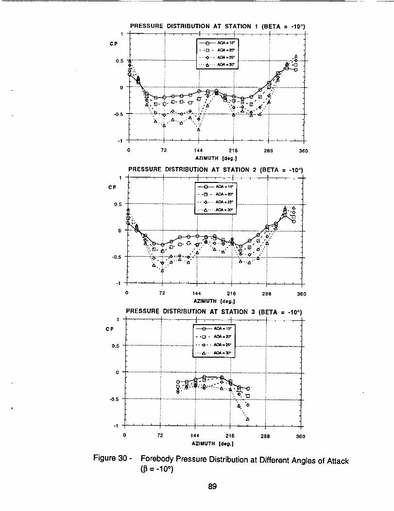
1
CP
0.5
0
-0.5
PRESSURE DISTRIBUTION AT STATION 1 (BETA = -10 _
......................... .,......................../ "" "O- - AOA-2S" ........................................ :A...
'" i ! i _'_,. _ i_ _ ,'_
_i} ........................... ;........................... i ..................... -,- ....................:. i i , _,..''_,', - _ i, _" ",,_._. #. i
'.._ _. .O..O,.._ :, .' .: _.',a.-" ' !.................. , "'_ ........... _,"';"_, "."..................... t_": ....... "_'_-_'""t .........................
-1 ' ' ' I ' ' ' I .........
0 72 144 216 288 360
AZIMUTH [deg.]
PRESSURE DISTRIBUTION AT STATION 2 (BETA = -10°,. ! =,=-!, , , !
I-'_- _'_'1 i.........................--........................t *- _'' _.......................i..........................
0 _-_i .......................... a............................ i;...........................................• 4>:.'- [] ,'_'
"' " e, "_' "" i'._-O'" ." i............... ".:_-"--_'":'..-_ - -_'_ -e; -" ÷ ............. ,;.......... :._..-.-! .......................... ,
k"_ t,." -,_ : ,_..,_.
'_ i i
-1 ' ' ' I ' ' ' ' ' ' I ' ' ' t • , ,I
0 72 144 216 288 360
AZIMUTH [deg.]
PRESSURE DISTRIBUTION AT STATION 3 (BETA = -10°., t I ,
_ AQA - lS°
................................................... _-- ._- - AQA.,25" ..............................................
• ..,A-.. AOA. 30"
0 .........................................................................................................................................
i °. •
.................................................................................. i---'-.-..... ;............... _..........................
i ", i
I I I i _ i i • J I , i | | i | II I
O 72 144 216 288 360
AZIMUTH [deg.]
1
CP
0.5
-0.5
1
CP
0.5
-0.5
Figure 30 - Forebody Pressure Distribution at Different Angles of Attack(B= -lo °)
89

CP
-0.5
PRESSURE DISTRIBUTION AT STATION 1 NO TAIL)
0.5 :"_" ........................................... ....&--- AOA= 3o" .......................
.............._,-_ ...........................!..................._ ...................t-_-;;_ ..........-1-
"",i "r_-B -r_- _. .o..e- " _,. "u- ._ "_ " i 4•.e.. o.o'i _...b..&..b.._....._ .
......................... &-.-.-e'-:-._ ......... :,_ ,:......; .......................... :-_-:---_-----%-- ......................"'_, .... .,,," ",,,' -A-..$
-I , , J J , , , , , , ' ' ' I ' ' '
0 72 144 216 288 360
AZIMUTH [deg.]
L --
STATION 1
I
_1 A PorIs_ - 20
L_ angle ¢
1
CP
0.5
CP
-0.5
PRESSURE DISTRIBUTION AT STATION 2 (NO TAIL)
i l--D- l_=2ff'
- - _> - - AQA=25°............................................................................................... STATION 2
...4°.. AO_.= 3o"
- ":3 i i ! _ 2_-4o
o ............._ .....T...........................[ ...........................":..........................._........,.. -......... t -
t_ '_: '_: m m" ...... " _3- _ _-_ _'.'Z: _ 12, Azimuth
l- "., "D"-'-'-' & "" "" "*--o--o-._-'U ." l
.o.__.......................;_".:"::_":--_-::_::"t.-..............':.;:"-"'-_::-_.......................I- " "ng""
-1 i i I
0 72 144 216 288 360
AZIMUTH [deg.]
PRESSURE DISTRIBUTION AT STATION 3 (NO TAIL)
, ! I
-G- AOA-20* !
0.5 ...... -_-- AGA.25" "............................................................................................ STATION3I
- - AOA = 3_' Pods 41 m _
0 ......................................................................................................................................... L R
..........................:_............_.._..-._..........................._........................_....................... @
@,.. .:
, , , i , , , i , , , i , , , _ , , ,-1 _ i _
0 72 144 216 288 360
AZIMUTH [dog.]
Figure 31 - Forebody Pressure Distribution at Different Angles of Attack
(No Tail, I_ = 0 °)
9O

CP
1
CP
0.5
EFFECT OF BLOWING (NOZZLE A, STATION 1)
...... t , , , t , , , I , , ,
|- -o - L30 => Cmu = 0.00075 t
...................... J-- -o-- L40 => Cmu = 0.001
"i.......................|..-,_-.. L50 => Cmu = 0.00125 | ...............
_i'_ ; |--e-i L60=>Cmu=O.O015i .',_j "_
..........................................................._-_-....:................................_.;.e ..............
-0.5 .......................... _....................................................... _.....................................................
0 72
1
0.5
-0.5 ....................................................
i , J I [ t i
0 72
144 216
AZIMUTH [deg.]
AOA= 15"
281t 360
Figure 32 -
L--
EFFECT OF BLOWING (NOZZLE A, STATION 2)
--D- L_ i
o ........................T.......................:::: ........................i......................
-0.5 .................................................... ._...........................:....................................................
AOA= 15°
-1 = J ' J I I I z i l , i i | , , II t
0 72 144 216 288 360
AZIMUTH [deg.]
EFFECT OF BLOWING (NOZZLE A, STATION 3)
-- - I.,30 :...... ° ..........................................................................................
0 ...................................................... ÷.................................................................................. L
AOA= 15°
ii l I i i I i I I
144 216 288 360
AZIMUTH [deg.]
Effect of Aft Blowing on Forebody Pressure Distribution
(Nozzle A, (z = 15 °, Left, Right and Both Sides)
a)
STATION 1
I
Ports _ - 20
Y Azlm_th
angle @
STATION 2
I
_21 AZ Pod: 21 - 40
im_th
angle @
STATION3I
-- ' Azlmulh
angle
91

1
CP
EFFECT OF BLOWING (NOZZLE A, STATION 1)
- -r_ - R30 => Cmu = 0.00075 I
o.5 ........................._................... -o-- R40 => Cmu = 0.001 j ..... /i ..-_... R50 => Cmu = 0.001251 ..........
i • R60 => Cmu = 0.0015 _
o L.._I -- - . I .;_.._
-0.5 ..................................................... [................................................................................
: AOA= 15°
=1 I I I , I i i I i i I I i I I I I
0 72 144 216 288 360
AZIMUTH [dog.]
EFFECT OF BLOWING (NOZZLE A, STATION 2)
...... !, .t. /
,,...........................-.........................o--- ........................i.........................
o ................... i..........................4...........................!...........................i....... _.; ..........
i i AOA = 15
-, ''' i ...... i''' '''/0 72 144 216 28B 360
AZIMUTH [deg.]
EFFECT OF BLOWING (NOZZLE A, STATION 3)
1
CP
0.5
.0.5
1
CP
0.5
-0.5
-1
i
--D- R30"'" -° °- R40
0 ........................................................................................................................................
'''l'''i'',i ......0 72 144 216 288 360
AZIMUTH [deg.]
Figure 32- Continued
b)
92

I
CP
EFFECT OF BLOWING (NOTTLE A, STATION 1)
i Ii - -D - B30 => Cmu = 0.00075 I
0.5 .........................-_.......................-- -o-- B40 => Cmu = 0.001 J..............." ! ---_.-- BSO=> Cmu = 0.00125
._. ii --.- B60=>Cmu=O.O015J,;.__• ,, • i i ! _ _'-
o ..................................-'-_-.: ..................::.............._: -. -.-:............................_.._,,.S................
-0.5 ......................................................_.................................................................................
-I
1
CP
0.5
i AOA = 15°
0 72 144 216 288 360
AZIMUTH [deg.]
EFFECT OF BLOWING (NOZZLE A, STATION 2)
--G- _
_ ._. i --e- _
o _m ....
.........................T..........................i...............................................................................i i AOA=Is.
" '''J'''J ...... I,,,0 72 144 216 288 360
AZIMUTH [deg.]
EFFECT OF BLOWING (NOZZLE A, STATION 3)
" "" °" 1340 ................. 4- ........................... _ .......................... 1..........................
0 ...................................................... - ........................... i ......................................................
-0.5
1
CP
0.5
-0.5 ......................... _............................. :-........................... _.......................................................
i AOA = 15=
-1 I I I i I I I ] = ' J I I I Il I I
0 72 144 216 288 360
AZIMUTH [deg.]
Figure 32- Concluded
c)
93

CP
1
CP
EFFECT OF BLOWING (NOZZLE A, STATION 1)
-_-.- BASEUNE'
--r_- 1.3o
O.S .................... ..,0- - t.,,=o ..................................................
o _L.....................__._..............................................................._ _-:,- ..i................................._ _............._
.,;,, L i ......... i ' ' 'l
0 72 144 216 288 360
AZIMUTH [deg.]
EFFECT OF BLOWING (NOZZLE A, STATION 2)
0.5 _ ........................i........................-o-- ,.,,o ........................i............................._.-. _ i
o .........."-_.......-;.........................._...........................i...........................i.........................
-0,5 ......................................................................................................................................
1
CP
0.5
Figure 33 -
AOA = 20'
0 72 144 216 288
AZIMUTH [deg.]
360
EFFECT OF BLOWING (NOZZLE A, STATION 3)_--_ t, 1 I ,7`
_ :
--D- _ i i _..... _.. _ ............... _ ..................................................................................
.,_... t_E
-0- _ i
0 ...................................................... _ ...................................................................................
i AOA = 2o=
0 72 144 216 288 360
AZIMUTH [dog,]
Effect of Aft Blowing on Forebody Pressure Distribution
(Nozzle A, o¢= 20 °, Left, Right and Both Sides)
a)
94

EFFECT OF BLOWING (NOZZLE A, STATION 1)
' --=- , , I ti ii............."...............o._ ................................................._.o.__ ...................
_ "_11 "_ _-_
0 _ ..... ;........................... ;........................... ;........................... <...................
-0,5 .................................................................................. ' .....................................................
AOA = 20°
I i I i i i • J i i i l l 1 •-1
1
CP
0 72 144 216 288 360
AZIMUTH [deg.]
EFFECT OF BLOWING (NOZZLE A, STATION 2)
0.5 ............................................. .0-- R40 ............................................
..._... R,S0 t
o .......... :; ....... _ ........................... !........................... !........................... , ....................... I°0,5 ..................................................... "."..................................................................................
AOA = 2O"
-1 , I I I , z i , i ¢ I I _ I I iI
0 72 144 216 288 360
AZIMUTH [dig.]
EFFECT OF BLOWING (NOZZLE A, STATION 3)
I I,. I ,,,_ BASEU_ _
1
CP
0.5
--[3- FI20
0 .............................................................................................................. * ..........................
.............. .I. ................................................................................
-0.5 .............................................................................................................. ,.........................
: AOA = 20 o
-, ' I ......... i '0 72 144 216 288
AZIMUTH [deg.]
360
Figure 33- Continued
b)
95

1
CP
0.5
EFFECT OF BLOWING (NOZZLE A, STATION 1)
.........................T..........................o-- =o ........................-.........................
o ...............................i...............-o.s .....................i ........................i.......................__.......................i ...................
-1
0 72 144 216 288 360
AZIMUTH [deg.]
EFFECT OF BLOWING (NOZZLE A, STATION 2)
o%i ......................!:_:i'_...........................!........._ ......015 ......................... __ .......................... _ ..................................................................................
1
CP
0.5
1
CP
0.5
-0.5
i _ AOA = 20_: i
"1 • J l | = I , I I I I i i I I
0 72 144 216 288
AZIMUTH [deg.]
-1
360
EFFECT OF BLOWING (NOZZLE A, STATION 3)
, , , ! ......... ! _ , , !
I-_-'_''_ t---I:-:-::...............,...............................................................................
...,,_... BSO i
0 72 144 216 288 360
AZIMUTH [deg.]
Figure 33- Concluded
c)
96

EFFECT OF BLOWING (NOZZLE A, STATION 1)
.... ....... '.... °
C P _ BASEUNE
- -r'-I - L3o
--.O- - L400,5 ...........................................................................
. -- -._--. L._ --
0 ........................ ' ........................... ;...................................................... +......................q : :
-0.5 .................. " >" " ".....
i =: AOA = 25°
-1 I l t
0 72 144 216 288 360
AZIMUTH [deg.]
EFFECT OF BLOWING (NOZZLE A, STATION 2)
CP --..-_-- _,_sm_
--[3- L_
0.5 ................................................... _>-- LAO ...........
,-_ , .-._,.-- L_ _a
o ...................................................................... iii ........................o_ .................._ ......._ ........................
1
CP
0.5
-0.5
-1
Figure 34 -
|lZi_il
AOA = 25°
I I [ ] I
0 72 144 216 288 360
AZIMUTH [deg.]
J ----e-- BASEUNE
--[3- L30
..... •O- - 1.40
---_--- LS0
--O-
EFFECT OF BLOWING (NOZZLE A, STATION 3)
I I t, ,, t
0 ...................................................... -' ...................................................................................
i .: AOA = 25"?
, , , J , , , i .........i I
0 72 144 216 288 360
AZIMUTH [deg.]
Effect of Aft Blowing on Forebody Pressure Distribution
(Nozzle A, _ = 25 °, Left, Right and Both Sides)
a)
97

CP
-0.5
EFFECT OF BLOWING (NOZZLE A, STATION 1)1 ......... I , , I
_ _u_
0.5 .................................................. ---0- -
--__ .'2"o ........................_i-i_x_........_...........................J_,:,_!......................................................-_'_.._ "_i........".....................
-I
1
CP
0.5
-0.5
1
CP
0.5
-0.5
AOA = 25°
i i i i i i I i i i
0 72 I44 216 288 360
AZIMUTH [deg.]
I
EFFECT OF BLOWING (NOZZLE A, STATION 2)
...... ! + ++ '1I-_-_'_ + t
..............................................................................+++7+AOA = 25 °
I i : 1 i , I : L iI
0 144 216 288 360
AZIMUTH [deg.]
-1
lllt,,it
72
BASEUNE
--D- 1:130
...... •.0- - PAO
•..._,.-- P,50
--0- RBO
EFFECT OF BLOWING (NOZZLE A, STATION 3)I I I I
I l ] 1 T ,
: i
. i
..........................1...........................T........:.L_:'_:_-............................................
........................_............_ ..................+2221....i i i i i i i , , , , , • , , ,
I
72 144 216 288
AZIMUTH [deg.]
360
Figure 34- Continued
b)
98

1
CP
0.5
-0.5
EFFECT OF BLOWING (NOZZLE A, STATION 1)
, , t ' , 1 .... I ' ' II i./-::.......................i..........................-o-- _ ......................_.........................
x_, ! i--0- BeO
............-_)..........;..........................._...........................i.........................:........._ ........: : : _. - .............
1
CP
0.5
-0.5
1
CP
0,5
-0.5
-1
AOA = 25°
0 72 144 216 288 360
AZIMUTH [deg.]
EFFECT OF BLOWING (NOZZLE A, STATION 2)
...... !,, I,,,l,,,1
--D- win i
.........................,........................1.-o.-- .......................i.........................1
%i'" " i _1"'_" _-_ i _1_I
0 ,, . ".......... _........................... i ........................... i ......................................................................J: AOA = 25°
-1 i l i I I I I I I I I i I I I II l
0 72 144 216 288 360
AZIMUTH [deg.]
EFFECT OF BLOWING (NOZZLE A, STATION 3)!
! _ eASEUNE
-- ,.,0- - B40 .............. "_........................... _"........................... ,t..........................
---_.-- B_
--0- _0
O ...................................................... "; .................................................................................
.....................................:_ __ -._i _--i_......................................." iZ21................
'''i'',t ...... i'''0 72 144 216 288 360
AZIMUTH [deg.]
Figure 34- Concluded
c)
99

a) 1
CP
EFFECT OF BLOWING (NOZZLE A, STATION 1)
...... !, ,,!, ,,, ,,,
0.5 _'._/_,_.................... "_........................ ... _... L_ ........................ _ .........................
o ! : .i tj t"& .' " ; -, i .......................
0 72 144 216 288 360
AZIMUTH [deg.]
EFFECT OF BLOWING (NOZZLE A, STATION 2)
:t...+--° .........._{.......T...........................i...........................!...........................7........................
,i il ,.............._.:.:.:.:.._...__:....:._ ........................
AOA : 30'
-0.5
1
CP
-0.5 -
-I
1
CP
0.5
-0.5
li i|1 ill iii
0 72 144 216 288 360
AZIMUTH [deg.]
EFFECT OF BLOWING (NOZZLE A, STATION 3)
-_, , , ...... ......I"
_ I.--_-=*_'"_I i
-I!."'"1'...........................---,_--- _ ..............T.... .....................i..........................
_ _ iii"i_!.....................i iT::i/:::.................................................
L ', gi "°"=i,,.i,_r,i .........
0 72 144 216 288 360
AZIMUTH [deg.]
Effect of Aft Blowing on Forebody Pressure Distribution
(Nozzle A, ¢x= 30 °, Left, Right and Both Sides)
L30 => Cmu = 0.00075
L40 => Cmu = 0.001
L50 => Cmu = 0.00125
L60 => Cmu ,=0.0015
Figure 35 -
100

b)1
CP
0.5
-0.5
-1
EFFECT OF BLOWING (NOZZLE A, STATION 1)
J ---.(_.-- BASEUNE'
..............................................................................................
..................... _........................... ;........................... _........................... .;.......... ;/ ............
AOA = 30 =
i I i I I I [ I I J
0 72 144 216 288
AZIMUTH [deg,]
EFFECT OF BLOWING (NOZZLE A, STATION 2)
! !
t ot0.5 ......................... _ ........................ -- "0,- - P.40 ....................... ............................
0
i
"'_-_ !" ¢ ' i ,oA--_ -
1
CP
0.5
360
-0.5
-1
-1 I I I I I J I I I I I I I I I I
0 72 144 216 288 360
AZIMUTH [deg.]
EFFECT OF BLOWING (NOZZLE A, STATION 3)
t --EP-.-- BASEUNE
--D- _
..... "0- - P,40 ............... * ........................... _.....................................................
. . . w. . . RSO i
--O- ReO i
0 .................................................................................. _.....................................................
:..."..'. -_. " -
0 72 144 216 288 360
AZIMUTH [deg.]
Figure 35 - Continued
R30 => Cmu = 0.00075 J
R40 => Cmu = 0,001 !R50 => Cmu = 0.00125
R60 => Cmu = 00015
101

c) 1
CP
0.5
-0.5
-1
1
Cp
0.5
o
-o.5
-1
1
CP
0.5
-0.5
-1
EFFECT OF BLOWING (NOZZLE A, STATION 1)
..... "'t__D__, BmBASEUNE'' t
........................................... "0--_ ........................ .,,¢........................
--0- B_ i
......................._............................i............................_.......................t.......... ..........i _ i ! ,
0 72 144 216 28B 360
AZIMUTH [deg.]
EFFECT OF BLOWING (NOZZLE A, STATION 2)
BASELINE
--[3- B30
._7.................... ..-_... as_'''O'-a_o...................................................._i........................../i
;........_......:--'-_ ....................................................i..........r ..........:
0 72 144 216 288 360
AZIMUTH [deg.]
EFFECT OF BLOWING (NOZZLE A, STATION 3)
BASEUNE
--[3- B0O
---O-- B_
. -_.-_--0- _
i
0 72 144 216 288 360
AZIMUTH [deg.]
Figure 35- Concluded
B30 => Cmu = 0.00075B40 => Cmu = 0.001
B50 => Cmu = 0.00125B60 => Cmu ,, 0.0015
102
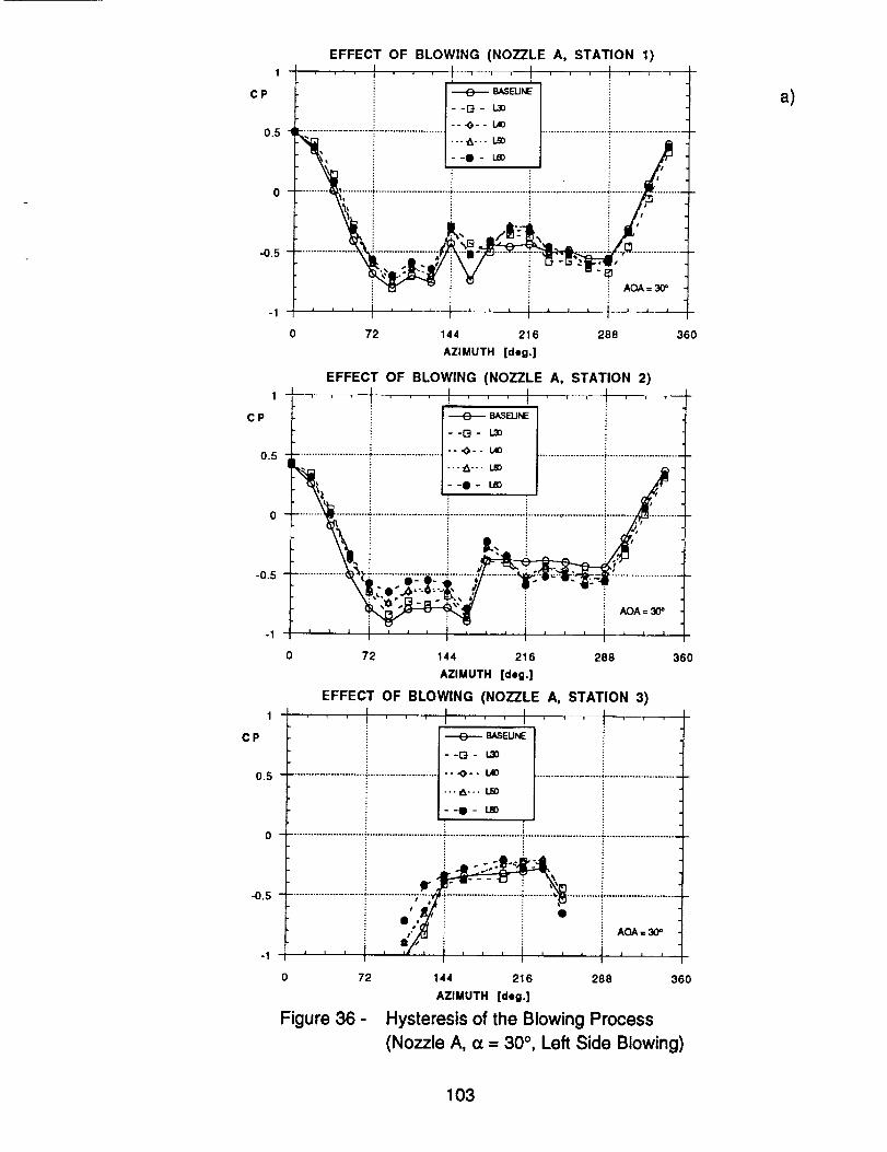
1
CP
EFFECT OF BLOWING (NOZZLE A, STATION 1)
_ ..... i !'''!
." _--o- '-',, i
................................. -- -,_° - L40 i
0 .......... _........... ;........................... i........................... i ........................... _.............................._i, _ _ _ ......" I _ i E ! i. .................................
0 72 144 216 288
AZIMUTH [deg.]
EFFECT OF BLOWING (NOZZLE A, STATION 2)
BASELINE
--13- L,_
0.5 .................................................. "" _" - I._ ........................ ,..........................
.._. -.-,a.- ,_ i- I : i J
0 ""i .......................... _......... _ .... , ........" i _ _ :• i _ : i
t't, :...................................._t; _".......e'._,-_-ii:-'_.........i.............................--.2:,,r;-,l-,;..,-i-;_• ,'0., - " t'_ ' AOA=30'
I l I l i = l | _ I I I I I J lm 1
I II I I
0 72 144 216 288
AZIMUTH [deg.]
EFFECT OF BLOWING (NOZZLE A, STATION 3)
, , , i _ i = I _ ' J
I
.................................................
0 ................................................................................. _ ......................................................
tr 'I i l
# : : :: # : : • :
0,, i i ii t i AOA = 30=
., ,,,,,'t,i,,,i,,,l,,,,0 72
1
CP
-0.5
1
CP BASELINE
--E}- L30
0.5 .................................................... ---o- - LAO
•..,_... LS0
-0.5
Figure 36 -
360
360
144 216 288 360
AZIMUTH [deg.]
Hysteresis of the Blowing Process
(Nozzle A, (x = 30 °, Left Side Blowing)
a)
103

1
CP
0,5
-0,5
-1
1
CP
-0.5
-1
1
CP
0.5
EFFECT OF BLOWING (NOZZLE A, STATION 1)
! ...... Ii i
----e----- BASEUNE I--[3- I..10
...... ---O-- 1.40
_" i_........................ _1""_"" _ ....................... -i .../.........................
.... i''-i ...... [.,,0 72 144 216 288 360
AZIMUTH [deg.]
-0.5
EFFECT OF BLOWING (NOZZLE A, STATION 2)
0.5 ......................... _"........................ -- "0- - 1.40 ................................---_$--- L_
--0- Leo
o .....................T..................................i.......................;........................................-'5+..........................- ......... -- " ------ ........................%
AOA = 30°
i i I i I /. 1 l i i i • 1 t
0 72 144 216 288 360
AZIMUTH [deg.]
EFFECT OF BLOWING (NOZZLE A, STATION 3), I
--[3- I._
"--'A--" L_
--I- U_
..........................]! _i................,.':i";"i"......................................_.......................................,o,:_-J I t I i 1 t i J _ I I I i I 1
l !
72 144 216 288 360
AZIMUTH [deg.]
Figure 36 - Concluded
b)
104

1
CP
0.5
-0.5
-1
1
CP
0.5
-0.5
-1
1
CP
0.5
-0.5
Figure 37 -
EFFECT OF BLOWING (NOZZLE A, STATION 1, NO TAIL
......................... _ ........................ _-_ _,- . _ ....................... T.........................
0 72 144 216 288 360
AZIMUTH [deg.]
EFFECT OF BLOWING (NOZZLE A, STATION 2, NO TAIL
l ! f !I -......_ B_._I.I_ _
--G- _
....... _...._ ....................... ..._,.. _ ..................................................
,,, .... i ...... i °0 72 144 216 288 360
AZIMUTH [deg.]
EFFECT OF BLOWING (NOZZLE A, STATION3, NO TAIL...... I I
, J--D- LS0.................................................. - ° ._t- - R.._}
f----A -. B_J ........................
. #. 4" "_ !
72 144 216 288 360
AZIMUTH [deg.]
Effect of Aft Blowing on Forebody Pressure Distribution
(No Tail, Nozzle A, (x = 25 °, Left, Right and Both Sides)
105

EFFECT OF BLOWING (NOZZLE A, STATION 1, NO TAIL
1 - , , T , , , I II ' _ i T l i i t
C P _ BASEUNE
- -r':l - L_
o.s _: ................7........................--.o--_ ........................T.................'_%
• i i
--'_ : : i "
o i i [] _ ::_.............. _........ _........................... , ...................................................... , .......... ;, ..........
i i _._-m- , i
AOA = 3O=
i i i I A i i i _ ,i [ i i iI
0 72 144 216 288 360
AZIMUTH [deg.]
EFFECT OF BLOWING (NOZZLE A, STATION 2, NO TAIL)
o.s _ ,,_-:-................T.......................... _>.. Rso ........................i........................."h, i .._,_ :: ._ :I"'_, '_ :.'---m i d/ i
:,71o ............,',.......T...........................i...........................i...........................i.........; ..........• i i m, i i
..................:: :]: " F"I" _" ....... 4: "- " .................
: AOA = 30'
l I I J | I I [ I I I I I I I I
m
0 72 144 216 288 360
AZIMUTH [deg.]
EFFECT OF BLOWING (NOZZLE A, STATION 3, NO TAIL
1 i I_ E
CP j _ BASI_NE i
0.5 .................. "_ .................................................................................
---O- - R50
...._... BS0
o ..........................i.........................._:_:: .............i...........................i..........................
-.0.5 '
AOA = 30=
-1 , , j , , , I , , , , , , , , ,!
0 72 144 216 288 360
AZIMUTH [deg.]
Figure 38 - Effect of Aft Blowing on Forebody Pressure Distribution
(No Tail, Nozzle A, (x = 30 °, Left, Right and Both Sides)
106

a) 1
CP
0.5
-0.5
-I
1
CP
0.5
-0.5
-1
1
CP
0.5
-0.5
-1
EFFECT OF BLOWING (NOZZLE B, 30° IN, STATION 1)J t , I , J
........................................... -- ._- - _40 ...................................................
--O- LeO
..:----" -- i /..... ..........................._...........................:.....................................
.............................. "_" i AOA= 25 °
z z l , , z I 1 I= i I I t I I I
0 72 144 216 288 360
AZIMUTH [deg.]
EFFECT OF BLOWING (NOZZLE B, 30 ° IN, STATION 2)
t,,, ......
' i ---._- -+ I-_ .... /
_................ .................AOA = 25 °
, l I I I _ I I II
0 72 144 216 288 360
AZIMUTH [deg.]
EFFECT OF BLOWING (NOZZLE B, 30° IN, STATION 3)I I ,-_-
F I '- or'l - 1.3o
"'" -''O-- _ ............... 4- ................................................................................
--Q- _
......................... i ............ P ................. < ..........................
! AOA = 25 °
I I I I I I I I I [ I I I ll
I t_I
0 72 144 216 288 360
AZIMUTH [deg.]
Figure 39 -
L30 => Cmu = 0.00075
L40 => Cmu = 0.001
L50 => Cmu = 0.00125
L60 => Cmu = 0.0015
Effect of Aft Blowing on Forebody Pressure Distribution
(Nozzle B301N, (z = 25 °, Left and Right Sides)
107

b)
EFFECT OF BLOWING (NOZZLE B, 30 ° IN, STATION 1)
--[3- _
0.5 .................... "_..................... -- -0- - mo ...............................................
'" i -.--A.-- _O
0 ....................................; ........................... i....................................................... _.......................
•-0.5 _ ,,
AOA=25"
l _ t 1 i , , _ • t 1 , ... t t ,-1
1
CP
0.5
o 72 144 216 288 360
AZIMUTH [deg.]
-0.5
-1
1
CP
0.5
-0.5
-1
EFFECT OF BLOWING (NOZZLE B, 30 ° IN, STATION 2)
f.......SASELJNe
--G- _
................................. -- -O- - _ ....................... !........................... !
--o-_ i ./o ", i i . i
: AOA=25°
t 1 t l I I , I I I J I | I I I I
0 72 144 216 288 360
AZIMUTH [deg.]
EFFECT OF BLOWING (NOZZLE B, 30 ° IN, STATION 3)
--i-4- _
...._... _
--o- R_
o ..........................i.......................................................i......................................................
.......................... i............ _ ............ ,..........................
AOA=25"
[ i i l i = i i l i I l I I I I
I
0 72 144 216 288 360
AZIMUTH [deg.]
Figure 39- Concluded
R30 => Cmu = 0.00075R40 ,,> Cmu ,, 0.001RS0 => Cmu = 0.00125R60 ,,> Cmu = 0.0015
108

1
CP
0.5
0
-0.5
-1
-1.5
1
CP
EFFECT OF BLOWING (NOZZLE B, 30 ° IN, STATION 1, , , ! , , , I , , , I , , , I , ,_
I '/...................r.........................---o-- _o ......................._.........................
........................ i ..........................."..........................._...........................- .....................
i 4_*" " i i "
i ;ti
i i ! ,, '
i AOA = 30_
0 72 144 216 288 360
AZIMUTH [deg.]
EFFECT OF BLOWING (NOZZLE B, 30 ° IN, STATION 2)
BASELINE
--G- 1.30
-°.0-- t_0.5 ......................................................................... i ..........................
--._-.. t,_
0 i .....":...........................":...........................":..........., ...........
_i o ! ! i ,
i: : •
• J I i i i l , • , I , , [ I j i l 1i ) I _ !
0 72 144 216 288 360
AZIMUTH [deg.]
EFFECT OF BLOWING (NOZZLE B, 30 ° IN, STATION 3)
! I [_e-- _.SEUNE i
--[3- _
.... "*" - _ ........................................... !.....................................................
---_--- L,._
--0- _
0 .........................................................................................................................................
-_i''' I''' i''' i .e. i'''0 72 288 360
-0.5
1
CP
0.5
-0.5
Figure 40 -
144 216
AZIMUTH [deg.]
Effect of Aft Blowing on Forebody Pressure Distribution
(Nozzle B301N, _ = 30 °, Left and Right Sides)
a)
109

1
CP
0.5
0
-0.5
-1
EFFECT OF BLOWING (NOZZLE B, 30 ° IN, STATION 1
, t , , ,i
BASEUNE
- -r-4 - R30
• ' ..................... -......................... "O - - R40 ........................ _ .........................
' i - -e - __ !....................... ;........................... ; ...................................................... ._......................
AOA = 30"
0 72 144 216 288 360
AZIMUTH [deg.]
1
CP
0.5
EFFECT OF BLOWING (NOZZLE B, 30° IN, STATION 2)
- -r'4 - _
-X....................... _ ....................... - - .O - - R40 ......................... _..........................
• i ---.A-.- _ .._--O- F_0
o .......... ,.i........._...........................i...........................i..........................._.........',:_ ...................._\-, , , _7.7?......'_,! _ ,<.i..,,.._,..,,..-,,...,,.._.;;l/
..................,...___...i-._.-.-lt:.._i._:i';.................
-1 ' ' ' ' ..... I ' ' ' t ' ' '
0 72 144 216 288 360
AZIMUTH [deg.]
EFFECT OF BLOWING (NOZZLE B 30° IN, STATION 3)
i t.__o-.._,... R._
l--t- _0 .................................................................................. ; .......................................................
.........................._............_!i_ ...........i..........................i _../l i ; \ ! AoA=_
0 72 144 216 288 360
AZIMUTH [deg.]
-0.5
1
CP
0.5
-0.5
-1
Figure 40- Concluded
b)
110

a)
1
CP
0.5
0
-0.5
EFFECT OF BLOWING (NOZZLE B, 30 ° OUT, STATION 1)
C P _ BASEUNE ii
--G-
05 .......................... : ....................... .- .0- - L40 ........................ - ........i .................i = ii --e ,_ i i
0 .......... ........................... _........................... _........................... _........................
-0.5 l
0 72 144 216 288 360
AZIMUTH [deg.]
EFFECT OF BLOWING (NOZZLE B 30 ° OUT, STATION 2)
L: AOA = 25=
-1 I L J _ i I I I t I I I I A I I
0 72 144 216 288 360
AZIMUTH [deg,]
EFFECT OF BLOWING NOZZLE B, 30 ° OUT, STATION 31
CP
0.5
:_ BASEUNE
- -I':1 - L_
--.,0-- L40
- - --_... I.._
--0- LeO
0 ............................................................................... i
AOA = 25"!
-1 ' ' ' i ......... j , , ,
0 72 144 216 288 360
AZIMUTH [deg.]
Figure 41 - Effect of Aft Blowing on Forebody Pressure Distribution
(Nozzle B3OOUT, _ = 25 °, Left and Right Sides)
L30 -> Cmu = 0.00075L40 -> Cmu - 0.001L50 => Cmu = 0.00125L60 => Cmu = 0.0015
111

b)EFFECT OF BLOWING (NOZZLE B, 30 ° OUT, STATION 1)
1 i I ' i i
; i t _ T I l
C P _ _ BASEUNE
--[3- ROO0.5 ............................................... ---o-- 940
o,°!......................( ................................:...................Z:.................._..........................
CP
I
CP
AOA = 25°
I ......... 1 ' '0 72 144 216 288 360
AZIMUTH [deg.]
iFFECT OF BLOWING (NOZZLE B, 30° OUT, STATION 2)
1 t [ t
1BASEUNE
--[3- R30
0.5 ................................................. -- "O- - Pa0
o_........:_....._........................_= .......................,.........
0.5
-0.5
-I
I I I I ' i ,
0 72 144 216 360
AZIMUTH [dog.]
AOA = 25°
l L J
288
EFFECT OF BLOWING (NOZZLE B, 30 ° OUT, STATION 3
! I i; i
_ _EU_
----6--- _ _:
--e- _ il
..........................!............ ..................ZIII....: i
I i J i , = z l • J I I i I I I I
I I
0 72 144 216 288 360
AZIMUTH [deg.]
Figure 41 - Concluded
R30 => Cmu = 0.00075R40 => Cmu = 0.001R50 => Cmu = 0.00125R60 => Cmu = 0.0015
112

1
CP
EFFECT OF BLOWING (NOZZLE B 30 ° OUT, STATION 1
1 1 ......, I .... t, _C P I -'_ BASEUNE
I --[3- 1.30
0.5 _" .................... •......................... -0- - L40 ......................... ::.........................
i AOA = 30_ ]
-11 ...... i ......... |
0 72 144 216 288 360
AZIMUTH [deg.]
EFFECT OF BLOWING (NOZZLE B, 30 ° OUT, STATION 2
0.5 ................. ---0-- _ ....................................................
fA_
-0.5 ' ......... .._
AOA = 30'
-_ _' ' 1 ' ' ' I .........
0 72 144 216 288 360
AZIMUTH [deg.]
EFFECT OF BLOWING NOZZLE B, 30 ° OUT, STATION 3
0.5 ..............._............................i...........................,..........................
1
CP BASEUNE
--[3- L,30
--'O- - L40
--._.--. LSO
--0- 1.60
i. :;_-'.-.. - .!_
°" ...........................................................................7..........................i i _.* i AOA 30'
._ , ,_ _, , i , , , i ,T, i ....
0 72 144 216 288 360
AZIMUTH [deg.]
Figure 42 - Effect of Aft Blowing on Forebody Pressure Distribution
(Nozzle B30OUT, e_= 30 °, Left and Right Sides)
a)
113

EFFECT OF BLOWING 'NOZZLE B, 30 ° OUT, ;TATION 1)
c p --e-- _u_;
--[3- FL30
0,5 .......................................................
CP
-0.5 -
°" I )
\i .............................
?
0 72 144 216 288 360
AZIMUTH [deg.]
"FFECT OF BLOWING (NOZZLE B, 30 ° OUT, STATION 2)
, I 1' ' [BASE;LINE
--[3- _
0.5 ................................................... .. _>-- R40
"_t -.._.-. P_o ,_i
o .........-_- ........., .........................--o- P_o ................................:,_ ...........- _ _ i i '. ! i i '
"_ _) AOA = 30'
A
0 72 144 216 288 360
AZIMUTH [deg.]
EFFECT OF BLOWING NOZZLE B, 30 ° OUT, STATION 3
•_._ BASELINE
-0.5
1
CP
0.5
-0.5
-1
--r_- R30............... 4. ................................................................................
--.O- - R40
.-..&... RSO
- -_, - R_O .................................................................................................
, , , , m , i , , , . , , , i i l-- I
72 144 216 288 360
AZIMUTH [deg.]
Figure 42- Concluded
b)
114

a)
EFFECT OF BLOWING (NOZZLE C, STATION 1)
1 ...... I ' .... .... |
C P I _ BASEUNEI
%,, f+°i...........................! _.:'41 i 2,_'"0
,_ + _ ^ _,_., "-.-,:_
-0,5 .................. _ ..................
+ + + _o_;+s°-i ' ' ' I ' ' ' + ...... i , , +,--
0 72 144 216 288 360
AZIMUTH [deg.]
EFFECT OF BLOWING (NOZZLE C, STATION 2)I ...... T , , , I , , , I , , ,
cp I -e-"_-_u'_ I !
i-+-° i +0.5 ......................... _ ....................... - - .0- - 1.4o ......................... i................
! l+°J++ I H+_0 .................... s ........................... +,............................................ i ...
,,+ i ! ! ..........' + + -_-+ i
-0.5 ..
+ + + i,o +I-1 , , , , , , l , l , , , I
0 72 144 216 288 360
AZIMUTH [deg,]
EFFECT OF BLOWING (NOZZLE C, STATION 3)/ /
0 ...................................................... " ..................................................................................
-0.5 ......................... <............ __._+.+._-.._.._ ............ _..........................
i ++++I l I l
0 72 144 216 288 360
AZIMUTH [deg.]
Figure 43 - Effect of Forward Blowing on Forebody Pressure Distribution
(Nozzle C, m = 25 °, Left and Right Sides)
L30 => Cmu = 0.00075L40 => Cmu = 0.001LS0 => Cmu = 0.00125L60 => Cmu = 0.0015
115

b)
-0.5 -
EFFECT OF BLOWING (NOZZLE C, STATION 1)
CP _
0.5 .......................................................................... 0-- mo ..........
AOA = 25=
-1
0 72 144 216 288 360
AZIMUTH [deg.]
EFFECT OF BLOWING (NOZZLE C, STATION 2)
I--_'_ _' 1--G- _ i
..................................................t-- O- - R_ ........................!........................"_.1-'_
o .-.........................._: ..........................
_, ,,,i ...... i,,,i,;__ '.0 72 144 216 288 360
AZIMUTH [dell.]
EFFECT OF BLOWING (NOZZLE C, STATION 3)
,l I ! t
t '...........................: i--[3- _ i _
..._... R,_
--0- _
0 ......................... i........................... - ..................................................................................
i _o"_
i :: AOA = 25°
1 I
0 72 144 216 288 360
AZIMUTH [deg.]
I
CP
0.5
-0.5
1 '
CP
0.5
-0.5
-1
Figure 43- Concluded
R30 => Cmu = 0.00075R40 => Cmu = 0.001R50 => Cmu = 0.00125R60 => Cmu = 0.0015
116
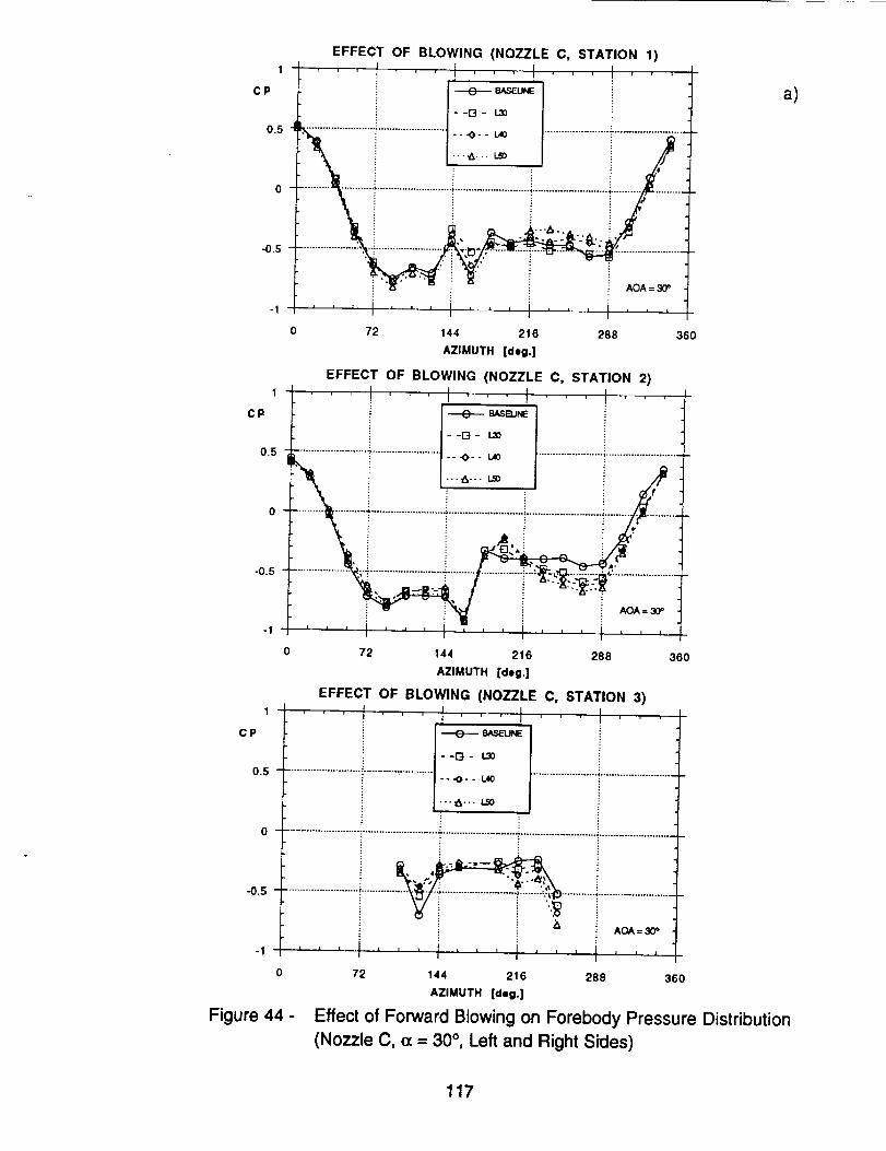
EFFECT OF BLOWING (NOZZLE C, STATION 1)
0.5 _ i _ i./"....................... _........................ - - -O- - L_ ....................... ?.........................
,__F i .......................7...........................T.......................
-1 ..... I'''1 ...... i'''
0 72 144 216 288 360
AZIMUTH [deg.]
EFFECT OF BLOWING (NOZZLE C, STATION 2)
C P _ SASBJNE
--_3- _
0.5 ........................ _ ........................
• --_-- 1.40 ....................... !..........................
0
-0.5 .................. ; T ................... -............................... " _.:......................
i " " i AOA = so"
-1 ' ' ' J, ' ' ' I ' ' ' I ......
0 72 144 216 288 360
AZIMUTH [deg.]
EFFECT OF BLOWING (NOZZLE C, STATION 3)
1 ...... I ' , , I ......
CP I _ e_SF-UNE
+ I -'G- _0.5 ................................................... -- "O- - 1.40 ....................... "..........................
I---_.-- LS0
++...................................... .................122...." '''1''' t'''1 '' 1I I I I I
0 72 144 216 288 360
AZIMUTH [deg.]
Figure 44 - Effect of Forward Blowing on Forebody Pressure Distribution
(Nozzle C, cx= 30 °, Left and Right Sides)
a)
117

1
CP
0.5
-0.5
-1
1
CP
0.5
EFFECT OF BLOWING (NOZZLE C, STATION 1)
i I :
...................... : ......................... "0- - _ ........................ _ .........................
..........._! ........_................._i_:"i ..................i'"" i _ ......' " 41" " "'" i i '
............ _.., >_:,_,.: -.._.;.'/_..__ ........................._._ _ :
, _ i l L r . I I ,L t t I I m A I I
0 72 144 216 288
AZIMUTH [deg.]
EFFECT OF BLOWING (NOZZLE C, STATION 2)
' ' ' ! ' ' ' I ....
--G- _
x,. i L--,- - j'o _-_:-'-'-_._............................._...........................i...........................;.........._.............
,_i i ; .......................
AOA = 30_
' ' ' I ' ' ' I .........0 72 144 216 288
AZIMUTH [deg.]
EFFECT OF BLOWING (NOZZLE C, STATION 3)
- I I,
-::-:-.0 .......................................................................... "'""°'_ ......................................................
......................i............ ...................22....
-0.5
-1
1
CP
0.5
-0.5
-1
360
0 72 144 216 288
AZIMUTH [deg.]
360
360
Figure 44- Concluded
b)
118

a)EFFECT OF BLOWING (NOZZLE D, STATION 1)
1 ' ' f ......... tcp I --°- _E''_ 1
Io.s .................................................,-- .<>--_o
0 /
"0.5
i i ii AOA=25°
0 72 144 216 288 360
AZIMUTH [deg.]
EFFECT OF BLOWING (NOZZLE D, STATION 2)
1L ...... I ...... I '
0.5 f ........................ T......................... .o-- L40 ......................... i:.........................
• i ""_" _ i
o - ..................T..........................._..........................._..........................i.........._.............
•_.5 ............ , ...........
i AOA = 25"
-I I I I _ _ J I| ' ' i lJ ) t ,_
0 72 144 216 288 360
AZIMUTH [dell.]
EFFECT OF BLOWING (NOZZLE D, STATION 3)1 , , , . , . , , , , , ,
cP J--o-- _u_
r--0- 1.30
0.5 "'" -- .0- - L40 ............... "_..................................................................................
----_- - • L,,._
--0- I.gO
0 ...................................................... ""....................................................... ,,..........................
..........................i............ .....................................! : AOA = 25 °
-1 ' ' ' I ' ' ' J ..... , ....
0 72 144 216 288 360
AZIMUTH [deil.]
Figure 45 - Effect of Forward Blowing on Forebody Pressure Distribution(Nozzle D, c¢= 25 °, Left and Right Sides)
L30 => Cmu = 0.00075L40 => Cmu = 0.001
LSO => Cmu = 0.00125
L60 => Cmu = 0.0015
119

b)1
CP
0.5
-0.5
-1
EFFECT OF BLOWING (NOZZLE D, STATION 1)
f , I
i --D- _ J
..................... _........................ ..._.. _ ! ....................... T.........................
•_.........i...........................i'-'_ .......i..........................i........._.,_.......
AOA = 25°
1 , 1 , , i t , J i l • t A ,
0 72 144 216 288 360
AZIMUTH [deg.]
1
CP
0.5
-0.5
-1
1
CP
0.5
-0.5
-1
EFFECT OF BLOWING (NOZZLE D, STATION 2)
--'0-- _
_....._........._.........................._:.'..-...._......._..........................._.........._..i.......
AOA = 25°
i i i i , i , , ,iJlillt
!
720 144 216 288 360
AZIMUTH [deg.]
EFFECT OF BLOWING (NOZZLE D, STATION 3)
I
t _ SASEUNE
--G- _
"" --.0-- _ ........................................... '_.....................................................
-..._... R._ i
--0- _ _
0 .................................................................................. _......................................................
....................i.....I............_ .......................................AOA = 25 _
, , , i , , , i ...... , , ,I 1
0 72 144 216 288 360
AZIMUTH [deg.]
Figure 45- Concluded
R30 => Cmu = 0.00075 1
R40 -> Cmu - 0.001
R50 => Cmu = 0.00125
R60 ,=> Cmu = 0.0015
120

EFFECT OF BLOWING (NOZZLE D, STATION 1)
°_ I-_- _°_1
- -E_ - L,.10
.............. _ -- ._- - La00.5"" ::........................ --. _-.. Lm ....................... T.....................
, ! --.-LEO i .
0 _ _," _ _ .:it _ / '/v_t-0.5
_3 i i i AOA =
-I ' ' ' i ' ' ' I ' ' ' I ' ' ' I ' ' ,
0 72 144 216 2BB 360
AZIMUTH [deg.]
EFFECT OF BLOWING (NOZZLE D, STATION 2)
CP _ E_SB.J_,E
--G- L30
--.0-- L400.5 ......................... _ ............................................... _..........................
--e- Leo
0 ...................... _................... _..................................... : ........... _......................
kl '.o.,.....................'._:-----._. _r=-_,.:.....................
"[3" i AOA = @0_
-1 , I I _ i I J I t I I I | i i 1
0 72 .144 216 288 360
AZIMUTH [deg.]
EFFECT OF BLOWING (NOZZLE D, STATION 3)
c,, t ]_._Eo_i i i i--o- _ i i io.,¢..t--o.._I...............i...........................i..........................._..........................--.- ,_ i ! i/
-0.5 .................................... _ ..................................
i i i i OA=:_
a)
0 72 144 216 288 360
AZIMUTH [deg.]
Figure 46 - Effect of Forward Blowing on Forebody Pressure Distribution
(Nozzle D, c_= 30 °, Left and Right Sides)
121

1
CP
0.5
-0.5
-1
1
CP
0.5
-0.5
1
CP
0.5
-0.5
-1
EFFECT OF BLOWING (NOZZLE D, STATION 1), , -'_'--1 -'--'--+-r'_++ ' ' r
IL_+__+,=o.+i
--G ° _ II
....'_i.......................I::.::-::.........................T............._
"",it-" + '_'_+ t't AOA = tIP
I I l I I .-I+ I + i ii i i i i i
0 72 144 216 288 360
AZIMUTH [deg.]
EFFECT OF BLOWING (NOZZLE D, STATION 2)
--D- R_
-_"+ki-_ +................................_.....+--_.i___i ........................_..........................•_:,..+,.:.,_.+..:;,+,+._..++:+..,.....................
Q,. ill: .,_.._b,,+" +" Eli "13 AOA = 30<,
I I i l i + l • i I I z i I I I
I
0 72 144 216 2Be 360
AZIMUTH [deg.]
EFFECT OF BLOWING (NOZZLE D, STATION 3)
i --o- _ !---t--o--_I...............+............................................................................+i..!..,.......+.!...............i...........................,..........................._...................................................i............,:°" ............i.........................
-- i _ AOA = 30_ -t
I I
0 72 144 216 288 360
AZIMUTH [deg.]
Figure 46- Concluded
b)
122

1
CP
0.5
-0.5
1
CP
0.5
-0.5
-1
1
CP
0.5
-0.5
_ eXSEUNE
--0- B30 i
---0-- Bao i
• .._-.. B50 i
--e- eeo
0 ...................................................... -:'..................................................................................
-1
EFFECT OF BLOWING (NOZZLE El, STATION 1)
t ......... ! '! ' J
--O- B._ i
....!......................................i.........
: ii
: AOA = 25°i
...... I ' ' ' I .......
0 72 144 216 288 360
AZIMUTH [deg.]
EFFECT OF BLOWING (NOZZLE El, STATION 2)
...... _!''!_;--.,,,_...... t
--G- B30 +........................................... ' ...... -- -O- - e,_ ........................ ':.........................
.-.-_- •. BSO i!
--4)- 1380 :i "
....................... T........................... "........................... ;........................... ;.......... , ............! ! ! i /
...
o
0 72 144 216 288 360
AZIMUTH [deg.]
EFFECT OF BLOWING (NOZZLE El, STATION 3)
,, I I I I
i :
: AOA = 25"
I I I I i i II',, i,'' I'''
0 72 144 216 288
AZIMUTH [deg.]
360
Figure 47 - Effect of Combined Blowing on Forebody Pressure Distribution
(Nozzle El, (z = 25 °)
B30 => Cmu ,, 0.00075
B40 => Cmu - 0.001
B50 --> Cmu = 0.00125
B60 => Cmu = 0.0015
123
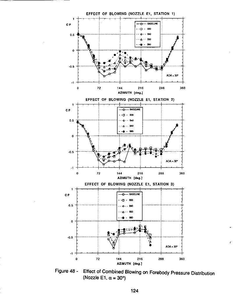
1
CP
0.5
0
-0.5
-1
1
CP
0.5
0
-0.5
-1
1
CP
EFFECT OF BLOWING (NOZZLE El, STATION 1)
,,, ! ...... !,,, !I-_o_ ii
--o- _ i......................... ":-........................... ;.................... "0- - B40 _.........................
i ?
0 72 144 216 288 360
AZIMUTH [deg.]
EFFECT OF BLOWING (NOZZLE El, STATION 2)
! !
. ........................T.........................-o-- s,,o ........................!...........................
__i.. i ...,_..._ i ,....i........................:.:.'..:...._....................................i......
\_f_-'_ i / - e'' ":_" " AOA = 30=
i I I 1 i i I i I i z i i _ [ i
72 144 216 288
AZIMUTH [deg.]
EFFECT OF BLOWING (NOZZLE El, STATION 3)
I I
--[3- _
0.5 .................................................. ..._.. 840 ..................................................
-°Q° _
-0.5
360
-1
0 .................................................................................. i ......................................................
i t
0
Figure 48 -
72 144 216 288 360
AZIMUTH [deg.]
Effect of Combined Blowing on Forebody Pressure Distribution(Nozzle E 1, _ = 30 °)
124

EFFECT OF BLOWING (NOZZLE E2, STATION 1)
1 ...... I , , , i , , , i , ,• , ¢
c P I L-e-- _._u_'
0.5 ............................................. - -C3 - L.30
0
-0.5 ii
i AOA = 25°
-I ' ' ' I ......... I ......
O 72 144 216 288 360
AZIMUTH [deg.]
EFFEC" OF BLOWING (NOZZLE E2, STATION 2)
c. f I+_,_
o:....................i...........................!...........................J...........................i.......................i i ._, ! !i i . i i
-0.5 '_ " " ' "<_ • : q' 1
! _; "
J i i ,o,._o-, '''1 ...... i'''i,,,/
0 72 144 216 288 360
AZIMUTH [deg.]
EFFECT OF BLOWING (NOZZLE E2, STATION 3)
0.5 "'" IJO ............... _............................ ,........................... _.........................
. k_
-0.5
1
CP
-1
Figure 49 -
L30'=> Cmu = 0.00075 l1.40 => Cmu - 0.001
i i i i AoA=_
'', i,,, i,, , i, ,-i, ,,72 144 216 288 360
AZIMUTH [deg.]
Effect of Combined Blowing on Forebody Pressure Distribution
(Nozzle E2, (x = 25 °, Left Side Blowing)
125

EFFECT OF BLOWING (NOZZLE E2, STATION 1)
1 i , , , I , ' ' ':
C P ---E)-- B_SEUNE
--D- I..30
0.5 _..........................i......................:-,,-- _ .........................7.........................
0 ...................... ; ........................... ;...................................................... <......................
7 " .8: ', _-0.5
• %_' • .- • ..-
AOA = 3(7'
-1 J J i J I I A I ' ' , , A _ , 1
0 72 144 216 288 360
AZIMUTH [deg.]
EFFECT OF BLOWING (NOZZLE E2, STATION 2) °
0.5 .................... _' ...........................................................
°!........:i...................................................iii!............................................._',. ¢..o.,. j O--o.._:-_:
i i x J l I | i 1 1 _ i 1 • i i
-I i i
0 72 144 216 288 360
AZIMUTH [deg.]
EFFECT OF BLOWING (NOZZLE E2, STATION 3)
CP I_ _'_1_
--1"4- 1.3o0.5 ............................................................................ _ ..........................
i0 ..................................................... _ ..............................................................................
|
-0.5 .......................... ' .......... _ "__I_ .....................................
A_=30 _
0 72 144 216 288 360
AZIMUTH [deg.]
Figure 50 - Effect of Combined Blowing on Forebody Pressure Distribution
(Nozzle E2, a = 30 °)
126

<zgQO
]=¢c
TIME LAG INVESTIGATION (AFT BLOWING)ALPHA = 2.5° - BETA - 0°
5000 , ;• , r t r
..... _ _ _ i _ _ i _ _ i i ! i i i i ! i'Tiii:o;_i_!;__;_i_;;i_._;;i;;-;;;;;i:_T......._--_-- i....• ' • "............................................._'__i .......i.......! i i L60=>Cmu=0.0015 i i _.._
! i i i _ _ _ _ __ i_-i i_x_;;_-;_-:_i ! -! i-............
J : : : i _ __]iiiiiiii!iiii_ii_ i]ii!iiiii[i_ ! , : : • " .... ._....... _........ ,."....... :.......z : i : i : : : : :
: _ i _ ! ........ .......:......._...............[........!.......i......." Ioo0_ _ , _ , -...... .............. .............. .......L __^...._..-/,,
-_o- i i ..!.... ! _ i i ! i i i i !
.......T.......i.......T.......i........."......._.........".......i.......?.......[........."......._"_-_o;__i;!;_'E"_s_i;'"i_;-_.....
....... + ....... _....... + ....... _....... + ....... ;....... _"....... _....... _........ _....... _........ ;....... _........ i....... _........ _....... _...... _._....... _.:......
......."..".......].......T.......i...............i.......'.-......._......._......._......."........i.......-........i.......-.........-.."................-..".......i........-so0o ,,, I ' ' _j i i i i ; i i i = = _
0.02 0.04 0.06 0.08 O.1
a)
TIME [ooc.]
5000 -
3OO0
1000
-1000
-3O0O
-5000
0
TIME LAG INVESTIGATION
ALPHA = 25 ° - BETA = 0 °
OLDWINGPRESSURe(LE_=T,
L60 -> Cmu = 0.00!5
ROLLIN(
".:, ..io" !o- .° • i
_..1.....!: : : i .
0.02 0.04
TIME [_©,]
BLOWING i PRESSURE
0.06 0.08 0.1
b)
Figure 51 - Time Response of Forces and Pressures to Blowing Inputs
(Nozzle A, Left Blowing, Cp. = 0.0015, c¢= 25 °)
127

-J,<Z_p(/)
,(rr
-5OOO
TIME LAG INVESTIGATIONALPHA = 30" - BETA = 0 °
I_LOWING IPRE._SUI_IE (LEFT_ 60 il_l)
L60 ,=> Cmu = 0.0015
• i iiENO_VCO
0 0.06 0.1
2 !(dg_)
: i
eLO_NG iPRESSU_E (m0aHT)
I L . -I I
0.08
TIME [',ec.]
a}
..i,<Z_o(/3
<n"
1 0OO
TIME LAG INVESTIGATION (AFT BLOWING)ALPHA ,_ 30 ° - BETA ,, 0 °
i'--_ i i I I l i t i _ i r r
)"...... "_....... ;....... "_....... ,;....... ÷ ....... _....... "_....... .;....... ÷ ....... ,;....... .:"....... "....... ,'-....... "....... _....... -.'....... "."....... - ....... ","....... "1: : ; : : : ,. . , ,
! BLOWING PRESSURE .(RIG ._. !
0 0.02 0.04 0.06 0.08 0.1
b)
Figure 52
TIME [_e¢.]
Time Response of Forces and Pressures to Blowing Inputs
(Nozzle A, Left Blowing, Cp = 0.0015, oc= 30 °)
128

50(_
3000
-5000
0
TIME LAG INVESTIGATION (AFT BLOWING)ALPHA =30 °. BETA = 0°
! SLOWING P_RES_;URI_ (LI_FT, 30
L60 => Cmu - 0.0015
i i _ i ii ROLUNG I MOMENT.'
.'i" _ _ ,!'"_..:...._.......;......._;,...._........_..; : .. i
i i'_
0.02
ENDEVCO;
0.04
i :
i',i
.;.......;........;.......!........_.,
ENDEVCO 7 (l_ft)
i i,"
.#....: ....... ! .......,!
(RIG I_T)
TIME [see.]
c)
5000
-1000-
-3000 -
-5OOO
0
TIME LAG INVESTIGATION (AFT BLOWING)ALPHA = 30° - BETA = 0°
BLOWINGI PeeSSU_E(LE_, =01p,I)
:! ROLLING MOMEN
'_i........ i......:._, ;....._.
0.02 0,04 0.06 0.08 0. I
TIME Isec.]
Figure 52- Concluded
d)
129

5000 '
3000 -
..J,(z0
_o_-
-11;100-
-3000 -
-5O0O
TIME LAG INVESTIGATION (AFT BLOWING)ALPHA = 30° - BETA © 0°
I I
• s I t I •• i I I I I I f I _ " i t I I I I
! ! ! ! ! ! ! ! ! ! ! ! ! : . :
...... _....... -"....... ._....... _....... _-...... . ....... :........ i....... :. ....... :............... _....... _........ _....... _........ ;....... "........ :........ "......
Zi!iZilZ!iiiiiiiiiiii__;_i.;.iZi!-_iiiiiiiiiill.....................................................................................
....... ._....... _....... $ ....... _.... _........ _....... _........ _....... _........ _....... _........ ;........ _........ ;....... ;........
71111111.......!iiiiTili/ri!._.iiiiil]ii_7-iiiiiiiiii!iiiiii_"! '.......................÷...............-:........................'................._......._......_--_,_-_--_-_::-x_;------.ooooo.oi'CE_)................ >....... , ........ ;....... , ....... _........ +....... _........ ;....... _........ ;....... ;........ _....... _........ )....... _........ , ....... _........ _....... , ........
..............!.......i.......i.......i.......i.......i.......i.......-.......i.......i........!.......-.......i.......i........i.......i........i.......i........
0 0.02 0.04 ).06 0.08 0.1
TIME [mec,]
a)
5000
3000-
-5000
0
TIME LAG INVESTIGATION (AFT BLOWING)ALPHA = 30 ° - BETA = 0 °
BLOWING _PRE$SURE
ENDEvCO
iENDEVCI
!
H
BLOWING_ PRESSURE (LEI_"
0.02 0.06 0.08 0.1
Figure 53 -
b)
TIME [111i¢.]
Time Response of Forces and Pressures to Blowing Inputs
(Nozzle A, Right Blowing, CI_ = 0.0015, (_ = 30 °)
_%-
130

5000
3000 -
o1000.
-5OOO
0
TIME LAG INVESTIGATION (AFT BLOWING)ALPHA = 30= - BETA = 0°
_ _ i - , .t i .t i _ i i i t _ i i i _ i-_......................................................................................................................................I ""']...... "_....... i ....... ._....... ;....... ",i-....... i ....... L ....... i ....... _........ I ....... _........ i ....... •........ i ....... i ........ _....... _........ ;....... ;........LbWIN'Q_ESSURe_(RC.NT.!60_,l) ' :: i i i i i
B60 => Cmu = 0.0015
,/'_'
i :I=NDEVCO
0.02
BLOWING
1 1
0.04
TIME {°ec.]
PRESSURE
ENOEVCO 1 i(lefti
0,06 0.08 0,1
a)
5000
-3000 -
-5000
0
TIME LAG INVESTIGATION (AFT BLOWING)ALPHA = 30° - BETA = 0°
i BL_WII_IG I_ESSUR|
l ;
i ROI;LIN(_ MOMENT
! :L/'_ ! ,.;o
o e ;. :" I : I
(RIGHT, i 60
i EN.DEVCO li0 (right)i
i i i ii i _ ! i
6 ileft) i
i..... ; ....... ..;.f ......
w
,
.!
JBLOWING"
....... _........ ; ...... _...-....;
i i ! _ i; i
PRi_SSU'RE(Le_r, _ poli _
i i i i i
0.02 0.04 0.06 O.OB O. 1
b)
Figure 54 -TIME [see.]
Time Response of Forces and Pressures to Blowing Inputs
(Nozzle A, Simultaneous Blowing, Cp. = 0.0015, (z = 30 °)
131

5000
TIME LAG INVESTIGATION (AFT BLOWING)ALPHA = 30 ° - BETA = -10 °
BLOWINGIPRESSU_iE(LEFTI6Oipe')i
L60 => Cmu = 0.0015
E
; ! :
ENDEV'CO il (left)
• I ! i .
I END.'EVC0 2 i(right)
! i ! i
i i i _ i
I
0 0.02 0.04 0.06 0.08 O. 1
TIME [see.]
a)
5000
3000-
-5OO0
0
TiME LAG INVESTIGATION (AFT BLOWING)ALPHA = 30° - BETA = -10°
BL_OWING PRES_;URE_ (RI_HT, i 60
i R6"0=>' Crr_ = 0.0015
i " i i _ i:_ ,iENI_EVCO• 1 i(iefti
2 (Hghl)
0.06
BLOWINGI PRESSURE iLEF_
0.02 0.04 0.08 O. 1
b)
Figure 55 -TIME [|ec.]
Time Response of Forces and Pressures to Blowing Inputs
(Nozzle A, Left and Right Blowing, Cp = 0.0015, o_= 30 °, [_= -10 °)
132

5000
TIME LAG INVESTIGATION (FORWARD BLOWING, C)ALPHA = 30 ° - BETA = 0 °
a)
3000-
Z
lOOO
re
-1000
-3000 -
-5O0O
0.02 0.04 0.06 0.08 O.I
TIME |sec.]
5000
3000-
.J
m 1000-
3:,,¢n-
-5OO0
o
TIME LAG INVESTIGATION (FORWARD BLOWING, C)ALPHA = 30 ° - BETA = 0 °
B_LOW_ING
ENDEVCO
_RE$SURE (RIGH'I', 60! pe_
i........_......._.....
BLOWING!PRESSURE
iii_i
0.02 0.04 0.06 0.08 0.1
b)
Figure 56 -TIME [*e¢.]
Time Response of Forces and Pressures to Blowing Inputs
(Nozzle C, Left and Right Blowing, CI.[ = 0.0015, (z = 30 °)
133

50O0
3000-
.=1
Zg#l 1000-
-1000-
-3O00_
-500O
TIME LAG INVESTIGATION (FORWARD BLOWING, C)
ALPHA = 30 ° - BETA ,= 0 °
, , t , , I , , _ I , , , l , , ,_ i ! ! _ i i i i _ ! ! ! " ! i "
...... _ ....... I ....... ,.:-....... i ....... 7,........ i ....... ,i........ t ....... ,i........!_!!!i!!!!!!!i!!!!ii_!!ii!!!!!!!!i!i!!!i!!!!!!!i!ii!!!ii!]i!!!i!_........ _....... ';........ I ....... _......... ; ....... 4........ _,....... i........
....... _,....... _....... _ ....... i ....... ,_....... l ....... _ ....... ;....... l ...... _....... i ........ ;....... _........ _....... : ....... ; ....... _........ ;....... ;........
....... ,,l,....... ;....... ,.l-....... ;....... ,l........ ;....... ,i........ ; .......... ;......... ' ..... ' ....
....... ,,l,....... ;....... _ ....... ;........ 4.
....... ,-:............... ,-i-.............. 4............. *-4-....... t....... ,i........ )....... ,[........ i ....... ,!........ )....... (........ _....... ,i........ _,....... i ........
i i i i i i i } i i i ! i i i i.......T.......i.......T...............T.......!......T......._........."......._.......T.......f.......T......._.......':......."7..'.......!.......7.......i........
i i i ] i i I i i i i i i i i iI I0.02 0.04 0.06 0.08 0.I
TIME [lic.]
c)
TIME LAG INVESTIGATION (FORWARD BLOWING, C)ALPHA = 30° - BETA = 0°
sooo-f---T , , , , " , , ".... l ' ' '
iiiiii_ i i i ! i ! i i i ! ! ! ! i ' :: :.
r-i .......!........!.......!........_.......i........!.......i........i.......!_ ......i.......1_ooo.......i_ ......_.......!......._......._.......-:......._ .......___ ...................................................,...............,........,....................,,i.....................................i........i..............:.......r......:......._.......:......._.......:......._.......:7:::::::::::::_-:::::::Ti!i;_::7:;iiil;i:::::i:::::::i:::::::
........ _....... _........ _....... _........ _....... _........ ;....... , ........ ,;..... , ........ ;....... _........ -;....... ;...... i ....... i ........ _....... 7........ _.......
1000,
,ooo_::::
-3ooo- ' : _ " _ " : " .'... _ : _......._ : _ .....i. : _ ..':...
........ ;....... i ........ i........ i ........ "....... ;........ ;....... ":........ i........ l ........ i........ _...... _....... i ....... -; ....... i ........ l, ....... _....... -_.......
......_........,T......"....'.......!.......7......i] .....].......7.........i.......-,,,"......i.......".......i.......".......i.......7.......!.......7.:.......
....... i........ ,i........ i ....... ,i........ i, ....... ¢........ i,....... (........ i,....... ,i........ i,....... i ........ I........ ,t....... -_....... ,I........ i. ....... ,i........ _.......
i ! i i i i i i J ; ; l _ : ; i ; ; ;-5000 i i t
0 0.02 0.04 0.06 0.08 0. I
TIME [lle¢.]
Figure 56- Continued
d)
P
134

TIME LAG INVESTIGATION (FORWARD BLOWING, C)ALPHA • 300 - BETA = 0°
5ooo BI
....... ......
....... ? ....... !........ _.............. _............. ¢........ _.................... _.....¢.., ....... _........ _....... _._.....;..t...._ ........ ; ....... ;.......
................. }....... ÷....._,_ ....... _........ _...... ,_....... _'....._.{....... - ....... !........
....... _....... !....... _"" . .... "_....... _........ " .... _........ _- -r'_...................... _.... "-_'"
-I000 : : : : : : : : : : _ '
: : _ : : T . * ...... :........ _....... :''7"': ....... :........
-3000
i i i i i i i i i i ! i ! ! i ! !.......-.......i.......-...............".......[.......T......._.......".......[......."......._.......".......[.......]................i.......-.......i........
0 0.02 0.04 0.06 0.08 O.1
TiME [sec.]
TIME LAG INVESTIGATION (FORWARD BLOWING, C)ALPHA ,, 30 ° - BETA ,, 0 °
3000 -
-lOOO -
-3ooo-
0.02
i ! :
! : : :
ENDEV_O t (leh)
:1
• : : "' : _ i1, i _ : * :" :..._........ _....... _........ )....... _._....&..t...._. : :
: : t i :
" i ,: ,! !i : iI
',! i.'! _...., "d""', ............... :'"¢ .
', i :' ! ! ".<.'_
o._ 0._ 0.08 0.1
TIME (eec.]
Figure 56- Concluded
e)
f)
135
Form Approved
REPORT DOCUMENTATION PAGE OMBNoo7o4-olo8Public reporting burden for this collection of information is estimated to average 1 hour per response, including the time for reviewing instructions, searching existing data source=.
gatheringand maintainin_,lthe data needed, and completing and reviewingthe collectionof information, Send commentsregarding this burdenestimateor any other aspect of thiscollectionof Inforhnation.includingsuggestionsfor reducing this burden, t0 WashingtonHeadquartersServices. Directoratefor informationOperations and Reports, 1215 JeffersonDavis Highway, Suite 1204, Arlington, VA 22202.4302, and to the Office of Management end Budget, Paperwork Reduction Pro_ect (0704-0188), Washington, DC 20503.
1, AGENCYUSE ONLY (Leave blank) 2. REPORT DATE ' 3. REPORT TYPE AND DATES COVERE[)
September 1993 Contractor Report4. TITLE AND SUBTITLE S. FUNDING NUMBERS
Aerodynamic Control of NASP-Type Vehicles Through Vortex
Manipulation, Volume II: Static Wind Tunnel Tests
6. AUTHORIS)
Carlos Su_irez, Brian R. Kramer, Brooke C. Smith, and
Gerald N. Malcolm
7. PERFORMING ORGANIZATION NAME(S) AND ADDRESS(ES)
Eidetics International, Inc.
3415 Lomita Blvd.
Torrance, CA 90505
9. SPONSORING/MONITORING AGENCY NAMEtS) AND ADDRESS(ES)
National Aeronautics and Space Administration
Washington, DC 20546-0001
NAS2-13196
8. PERFORMING ORGANIZATIONREPORT NUMBER
A-93138
10. SPONSORING/MONITORINGAGENCY REPORT NUMBER
NASA CR-177626
11. SUPPLEMENTARY NOTES
Point of Contact: Larry Meyn, Ames Research Center, MS 247-2, Moffett Field, CA 94035-1000
(415) 604-5038
12x. DISTRIBUTION/AVAILABILITY STATEMENT
Unclassified-Unlimited
Subject Category - 02
12b. DISTRIBUTION CODE
13. ABSTRACT (Maximum 200 words)
Forebody Vortex Control (FVC) has been explored in this research program for potential application to a
NASP-type configuration. Wind tunnel tests have been conducted to evaluate a number of jet blowing schemes.
The configuration tested has a slender forebody and a 78 ° swept delta wing. Blowing jets were implemented on
the leeward side of the forebody with small circular tubes tangential to the surface that could be directed aft,
forward, or at angles in between. The effects of blowing are observed primarily in the yawing and rolling moments
and are highly dependent on the jet configuration and the angle of attack. Results show that the baseline flow field,
without blowing activated, is quite sensitive to the geometry differences of the various protruding jets, as well
as being sensitive to the blowing, particularly in the angle of attack range where the forebody vortices are naturally
asymmetric. The time lag of the flow field response to the initiation of blowing was also measured. The time
response was very short, on the order of the time required for the flow disturbance to travel the distance from the
nozzle to the specific airframe location of interest at the free stream velolcity. Overall, results indicate that sizable
yawing and rolling moments can be induced with modest blowing levels. However, direct application of this
technique on a very slender forebody would require thorough wind tunnel testing to optimize the jet location and
configuration.
14. SUBJECT TERMS
Generic hypersonic configuration, Forebody vortex control, Wing rock
suppression, Experimental/simulation, Aerodynamic control
17. SECURITY CLASSIFICATION 18. SECURITY CLASSIFICATION 19. SECURITY CLASSIFICATIONOF REPORT OF THIS PAGE OF ABSTRACT
Unclassified Unclassifiedi
NSN 7540-01-280-5500
lS. NUMBER OF PAGES
14416. PRICE CODE
A0720. LIMITATION OF ABSTRACT
Standard Form 298 (Rev. 2-89)Prerlcttbed by ANSI Std. Z39-18290-102