AERODROME DESIGN MANUAL - Nigerian Civil …ncaa.gov.ng/media/1203/doc-9157-part-5.pdfAerodrome...
97
AERODROME DESIGN MANUAL PART 5 ELECTRICAL SYSTEMS FIRST EDITION - 1983 Approved by the Secretary General and published under his authority INTERNATIONAL CIVIL -4VI-ATION ORGANIZATION
-
Upload
nguyenliem -
Category
Documents
-
view
271 -
download
4
Transcript of AERODROME DESIGN MANUAL - Nigerian Civil …ncaa.gov.ng/media/1203/doc-9157-part-5.pdfAerodrome...

AERODROME
DESIGN
MANUAL
PART 5
ELECTRICAL SYSTEMS
FIRST EDITION - 1983
Approved by the Secretary General and published under his authority
INTERNATIONAL CIVIL -4VI-ATION ORGANIZATION

Aerodrome Design Manual
(Doc 9157-AN/901)
Part 5
Electrical Systems
First Edition - 1983

AMENDMENTS
Amendments are announced in the supplelnenfs to the Catalogue of ICAO Publications; the Catalogue and its supplements are available on the ICAO website at www.icao.int. The space below is provided to keep a record of such amendments.
%%ECO;taD OF AMENDMENTS AND CORRIGENDA
CORRIGENDA
--p-
p----
--.--.-pp
------p-
---.---
-.--p- ..
--.---p .-
p-
-
W----
-------
.-
.

Proper d e s i g n , i n s t a l l a t i o n and maintenance of e l e c t r i c a l sys tems f o r n a v i - g a t i o n a i d s , both v i s u a l and n o n v i s u a l , a r e p r e r e q u i s i t e s f o r t h e s a f e t y , r e g u l a r i t y , and e f f i c i e n c y of c i v i l a v i a t i o n . To t h i s end, t h i s manual p rov ides guidance on t h e d e s i g n and i n s t a l l a t i o n of e l e c t r i c a l systems f o r aerodrome l i g h t i n g and r a d i o naviga- t i o n a i d s .
The e l e c t r i c a l systems f o r aerodrome l i g h t i n g and r a d i o n a v i g a t i o n a i d s i n c l u d e f e a t u r e s which a r e n o t u s u a l l y involved i n o t h e r e l e c t r i c a l i n s t a l l a t i o n s . This manual t h e r e f o r e d i s c u s s e s n o t o n l y t h e g e n e r a l f e a t u r e s of e l e c t r i c a l p r a c t i c e s and i n s t a l l a t i o n s bu t a l s o t h o s e f e a t u r e s which a r e of s p e c i a l s i g n i f i c a n c e f o r aerodrome i n s t a l l a t i o n s . It i s assumed t h a t r e a d e r s of t h e manual w i l l be f a m i l i a r w i t h e l e c - t r i c a l c i r c u i t s and g e n e r a l d e s i g n concep t s , but may no t be knowledgeable of c e r t a i n f e a t u r e s of aerodrome i n s t a l l a t i o n s which a r e l e s s f r e q u e n t l y encoun te red i n o t h e r i n s t a l l a t i o n s . It i s important t o n o t e t h a t t h e m a t e r i a l p resen ted i n t h i s manual i s i n t e n d e d t o complement n a t i o n a l s a f e t y codes r e l a t e d t o e l e c t r i c a l i n s t a l l a t i o n s .
The manual does n o t d i s c u s s e l e c t r i c a l systems f o r b u i l d i n g s l o c a t e d on a n a i r p o r t o t h e r than t h e e f f e c t of such b u i l d i n g s on t o t a l power requ i rements f o r primary and secondary power s u p p l i e s . S i m i l a r l y , t h e manual does n o t d e a l w i t h t h e maintenance o f e l e c t r i c a l sys tems. For guidance on t h i s l a t t e r i s s u e t h e r e a d e r is a d v i s e d t o r e f e r t o t h e A i r p o r t Se rv ices Manual, (Doc 9137) , P a r t 9, A i r p o r t Maintenance P r a c t i c e s .
Fu tu re e d i t i o n s of t h i s manual w i l l be improved on t h e b a s i s of e x p e r i e n c e ga ined and of comments and s u g g e s t i o n s rece ived from u s e r s of t h i s manual. Readers of t h i s manual a r e i n v i t e d t o g i v e t h e i r views, comments and s u g g e s t i o n s t o t h e Secre ta ry General of ICAO.


Chapter 1 . I n t r o d u c t i o n .................................................... 5-1 1.1 Purpose ............................................................ 5-1 1.2 Organ iza t ion of t h e manual ............................................ 5-1
............................................ Chapter 2 . E l e c t r i c i t y Supp l ies 5-2
2'1 Sources of power ......................... ~ ~ P O O O O O O O O i O O O ~ e ~ ~ ~ ~ ~ ~ ~ ~ ~ 5 - 2 2.1.1 General ..................................................... 5-2 ....................................... 2.1.2 Primary power s o u r c e s 5-2 2.1.3 Secondary power s o u r c e s ..................................... 5-2 .......................... 2.1.4 D i s t r i b u t i o n of i n t e r m e d i a t e power 5-3
2.2 Power t r a n s f e r c h a r a c t e r i s t i c s ...................................... - 3 2.2.1 Trans fe r ( swi tch-over ) t ime requirements .................... 5-3 2.2.2 Continuous power s o u r c e s .................................... 5-3 2.2.3 Methods of t r a n s f e r ......................................... 5-5
2.3 Secondary power equipment .......................................... 5-7 2.3.1 Components .................................................. 5-7 2.3.2 Engine-generator s e t s ....................................... 5-9 2.3.3 Power t r a n s f e r swi tch ing .................................... 5-10 .............................. 2.3.4 U n i n t e r r u p t i b l e power s u p p l i e s 5-10 ............................. 2.3.5 S p e c i a l secondary power d e v i c e s 5-11
2.4 Vaul t s and s h e l t e r s f o r e l e c t r i c a l equipment ....................... 5-11 .................................................... 2.4.1 Shelters 5-11 2.4.2 Laca t ion .................................................... 5-13 .......................................... 2.4.3 S p e c i a l p r o v i s i o n s 5-13
2.5 D i s t r i b u t i o n of power .............................................. 5-14 ..................................................... 2s5sl General 5-14 2.5.2 Primary power f e e d e r c i r c u i t s ............................... 5-15 2.5.3 Above-ground (overhead) primary d i s t r i b u t i o n sys tems .......=5-- 15 2.5.4 Line-voltage r e g u l a t o r s ....................... 6 ( r ( r ( r ( r ( r ( r ( r O s D D D D 5 5 i 5 ................................................. 2.5.5 Power l i n e s 5-16 2.5.6 Conductors .................................................. 5-16 .................................................. 2.5.7 I n s u l a t o r s 5-17 2.5.8 Lacknuts .................................................... 5-18 ................................................ 2.5.9 Transformers 5-18 2.5.10 Capac i to r s .................................................. 5-19 ................................ 2.5.11 C i r c u i t i n t e r r u p t i o n d e v i c e s 5-19 2.5.12 Lightning p r o t e c t i o n ........................................ 5-20 .................................................. 2.5.13 Clearances 5-20 2.5.14 Grounding ................................................... 5-20 ............................ 2.5.15 Underground d i s t r i b u t i o n systems 5-21

Chapter 3 . E l e c t r i c a l C i r c u i t s f o r Aerodrome Ligh t ing and Radio Navigation Aids ........................................................... 5-23
....................................... Types of e l e c t r i c a l c i r c u i t s 5-23 3.1.1 E l e c t r i c a l c h a r a c t e r i s t i c s .................................. 5-23 ............................................. 3.1.2 S e r i e s c i r c u i t s 5-23 3. 1.3 P a r a l l e l c i r c u i t s ........................................... 5-24 ......... 3.1.4 Comparison of s e r i e s and p a r a l l e l l i g h t i n g c i r c u i t s 5-25 ............................ S e r i e s c i r c u i t r y f o r aerodrome l i g h t i n g 5-25 .................................... 3.2.1 Fac to r s t o be cons ide red 5-25 P a r a l l e l ( m u l t i p l e ) c i r c u i t r y ...................................... 5-41 3.3.1 Use of p a r a l l e l ( m u l t i p l e ) c i r c u i t r y i n aerodrome l i g h t i n g .. 5-41 .............................. Cont ro l of aerodrome l i g h t i n g systems 5-42 ........................................... 3.4.1 Control c i r c u i t r y 5-42 3.4.2 Cont ro l pane l s .............................................. 5-43 3.4.3 Use of r e l a y s ............................................... 5-44 3.4.4 I n t e r c o n n e c t i o n of c o n t r o l s ................................. 5-45 3.4.5 Automatic c o n t r o l s .......................................... 5-45 3.4.6 Radio remote c o n t r o l s ....................................... 5-46 .............................................................. Lamps 5-46 3.5.1 C h a r a c t e r i s t i c s of incandescen t lamps ....................... 5-46 .................. 3.5.2 C h a r a c t e r i s t i c s of g a s e o u s d i s c h a r g e lamps 5-48 Methods of o b t a i n i n g i n t e g r i t y and r e l i a b i l i t y f o r aerodrome
l i g h t i n g ......................................................... 5-49 3.6.1 D e f i n i t i o n of terms ......................................... 5-49 3.6.2 Summary of means of improving e l e c t r i c a l i n t e g r i t y
and r e l i a b i l i t y ........................................... 5-50 M f n i t o r i n g of aerodrome l i g h t i n g c i r c u i t s .......................... 5-51 3.7.1 Methods of moni tor ing . ~ ~ ~ ~ ~ . ~ ~ e ~ e ~ ~ ~ ~ . ~ ~ . ~ ~ ~ ~ e 6 6 6 6 6 L i 5 i i i 0 . 0 5-51 p t - *
3.7.2 Design of moni tor ing d e v i c e s ................................ 3-3"
3.7.3 Classes of moni tors .......................................a. 5-51 ................................... 3.7.4 Monitor o v e r r i d e c o n t r o l s 5-52 E l e c t r i c a l c i r c u i t s f o r r a d i o n a v i g a t i o n a i d s ..................a.e. 5-52 3.8.1 Types of r a d i o n a v i g a t i o n a i d s .............................. 5-52 3.8.2 E l e c t r i c a l c h a r a c t e r i s t i c s ....................C*...... e e a O O 0 5 - 5 2 3.8.3 Control c i r c u i t s f o r r a d i o n a v i g a t i o n a i d s .................. 5-53 3.8.4 R e l i a b i l i t y and i n t e g r i t y of r a d i o n a v i g a t i o n a i d s .......... 5-54 3.8.5 Monitoring of r a d i o n a v i g a t i o n a i d s ......................... 5-54 Acceptance t e s t i n g of aerodrome e l e c t r i c a l c i r c u i t s ................ 5-54 3.9.1 Appl ica t ion ................................................. 5-54 3.9.2 Guarantee p e r i o d ............................................ 5-55 ....................................... 3.9.3 Inspec t ion procedures 5-55 3.9.4 E l e c t r i c a l t e s t of s e r i e s - c i r c u i t equipment ................. 5-57 3.9.5 E l e c t r i c a l t e s t s of o t h e r c a b l e s ............................ 5-59 3.9.6 E l e c t r i c a l t e s t s of r e g u l a t o r s .............................. 5-60 ....................................... 3.9.7 Troubleshoot ing t e s t s 5-61 3.9.8 E l e c t r i c a l t e s t s of o t h e r equipment .........*...........*... 5-62 ........................................... 3.9.9 Tes t s of moni tors 5-62

Table of Contents ( v i i >
Chapter 4 . Underground E l e c t r i c a l Systems ........................I..*...... 5-63 ............................................... 4.1 General requirements 5-63
4.1.1 I n i t i a l c o n s i d e r a t i o n s ........................................ 5-63 ................................ 4.1.2 P r e c o n s t r u c t i o n arrangements 5-63 ..................................... 4.1.3 Methods of i n s t a l l a t i o n 5-63 ............................................. 4.2 Direc t b u r i a l of c a b l e 5-63 4.2.1 Steps of i n s t a l l i n g ......................................... 5-63 ................................................... 4.2.2 Trenching 5-63 4.2.3 S e p a r a t i o n between c a b l e s ................................... 5-64 ........................ 4.2.4 I n s t a l l a t i o n of d i r e c t - b u r i a l c a b l e s 5-65
4.3 I n s t a l l a t i o n of d u c t s ( c o n d u i t ) .................................... 5-66 ...................... 4.3.1 I n s t a l l a t i o n t echn iques and procedures 5-66 4.4 Manholes and handholes ............................................. 5-67 ................................................... 4.4.1 S e l e c t i o n 5-67
4.4.2 b c a t i o n .................................................... 5-69 4.4.3 Stubs ....................................................... 5-69 4.4.4 Hardware .................................................... 5-69 ........................................ 4.4.5 T w o s e c t i o n manholes 5-69
4.5 I n s t a l l a t i o n of underground c a b l e s ................................. 5-69 ........................................ 4.5.1 P r e p a r a t i o n of d u c t s 5-69 4.5.2 Cable p u l l i n g i n d u c t s ...................................... 5-69 4.5.3 I n s t a l l a t i o n of c a b l e i n manholes and handholes ............. 5-71 4.5.4 P r e s s u r i z e d type c o a x i a l c a b l e s ............................. 5-72 4.5.5 Cable i n s t a l l a t i o n i n saw c u t s ............................. 5-73 405.6 Cable marking . . ~ . e . . . . . . . . e . . . . . e . ~ e . . . . . . ~ e D i i 5 e i 6 6 i e e e ~ a e e 5 - 7 4 4.5.7 Enclosures f o r connec t ions .................................. 5-75
.................... Chapter 5. Cables f o r Underground Serv ice a t Aerodromes 5-77
5.1 Fea tu res of t h e c a b l e s . . . . . . e . . . . . . . . . . . . . . . e C e . . a e a e . O . I ) . . . . . . . . . . . . 5-77 5.1.1 C h a r a c t e r i s t i c s of c a b l e s f o r underground s e r v i c e ........... 5-77 5.1.2 Classes of s e r v i c e .......................................... 5-79 5.1.3 Causes of c a b l e damage ...................................... 5-80 .................................................. 5.2 Cable connec t ions 5-82 5.2.1 Cable s p l i c e s ............................................... 5-82 5.2.2 Taped s p l i c e s ........................................a.....e 5-83 5.2.3 Connector k i t s f o r aerodrome l i g h t i n g ....................... 5-85 .............................................. 5.2.4 Coaxial c a b l e s 5-85 5.2.5 Connection of conductors .................................... 5-88

1.1 PURPOSE
1.1.1 To ensure t h e r e g u l a r i t y and s a f e t y of a v i a t i o n , i t i s n e c e s s a r y t h a t a e r o - drome l i g h t i n g and r a d i o n a v i g a t i o n a l a i d s have high i n t e g r i t y and r e l i a b i l i t y . It i s cons idered t h a t t h e p r o b a b i l i t y of f a i l u r e of w e l l des igned and mainta ined l i g h t i n g and r a d i o a i d s a t a c r i t i c a l moment i s extremely low,
1.1.2 The fo l lowing m a t e r i a l i s in tended as a guide t o t h e recommended e l e c t r i c a l e n g i n e e r i n g p r a c t i c e s f o r des ign and i n s t a l l a t i o n of new systems and t h e modi f i ca t ion of e x i s t i n g systems of aerodrome f i x e d l i g h t i n g and of d i s t r i b u t i o n of power t o r a d i o n a v i g a t i o n a i d s . It does n o t imply t h a t e x i s t i n g i n s t a l l a t i o n s , i f d i f f e r e n t , a r e wrong and shou ld be changed a u t o m a t i c a l l y . It does mean t h a t some of t h e e a r l i e r des igns adopted a r e n o t recommended f o r r e p e t i t i o n s i n c e they have been superseded by l a t e r t h i n k i n g . Because of t h e d i f f e r e n c e s i n e n g i n e e r i n g s t y l e and equipment i n d i f f e r e n t c o u n t r i e s , t h i s m a t e r i a l e s t a b l i s h e s on ly b a s i c des ign p r i n c i p l e s . It i s n o t in tended t o i l l u s t r a t e d e t a i l e d des ign o r p a r t i c u l a r p i e c e s of equipment o r sys tems unique t o any one S t a t e .
1.1.3 The e l e c t r i c a l systems f o r aerodrome v i s u a l a i d s and n a v i g a t i o n systems r e q u i r e good q u a l i t y i n s t a l l a t i o n s and c o n s i d e r a t i o n f o r f e a t u r e s which a r e no t u s u a l l y invo lved i n o t h e r e l e c t r i c a l i n s t a l l a t i o n s . This manual d i s c u s s e s t h e g e n e r a l f e a t u r e s o f e l e c t r i c a l p r a c t i c e s and i n s t a l l a t i o n s w i t h emphasis on t h o s e f e a t u r e s which a r e l e s s commonly involved o r have s p e c i a l s i g n i f i c a n c e f o r aerodrome o p e r a t i o n s . It i s assumed t h a t t h o s e u s i n g t h i s manual w i l l be f a m i l i a r w i t h e l e c t r i c a l c i r c u i t s and g e n e r a l p r a c t i c e s but may n o t be knowledgeable of c e r t a i n f e a t u r e s of aerodrome i n s t a l l a t i o n s which a r e l e s s f r e q u e n t l y encountered i n o t h e r e l e c t r i c a l systems. Some of t h e s e f e a t u r e s a r e tha t most e l e c t r i c a l c i r c u i t s a r e i n s t a l l e d underground, s e r i e s c i r c u i t s a r e used f o r most l i g h t i n g systems, h i g h e r r e l i a b i l i t y i s r e q u i r e d o f t h e i n p u t power s o u r c e s , and r a p i d , au tomat ic t r a n s f e r t o secondary power i n c a s e of power f a i l u r e s . Each aerodrome i s unique, and i t s e l e c t r i c a l i n s t a l l a t i o n should be des igned t o provide economically power and c o n t r o l which is s a f e , r e l i a b l e , and e a s i l y mainta ined.
1.2 ORGANIZATION OF THE :NNUAL
1.2.1 This manual provides in format ion on t h e E l e c t r i c i t y Suppl ies i n Chapter 2, E l e c t r i c a l C i r c u i t s f o r Aerodrome Ligh t ing and Navigation Aids i n Chapter 3, Underground E l e c t r i c a l Systems i n Chapter 4 , and Cables f o r Underground Serv ice a t Aerodromes i n Chapter 5.

2.1 SOURCES OF POWER
2.1.1 General
2.1.1.1 The primary s o u r c e s of power f o r aerodromes should be determined b e f o r e t h e d e s i g n s of t h e aerodrome l i g h t i n g i n s t a l l a t i o n s and t h e r a d i o n a v i g a t i o n a i d s are i n i t i a t e d . The e l e c t r i c a l power f o r t h e s e i n s t a l l a t i o n s i s u s u a l l y on ly a s m a l l p a r t of t h e e l e c t r i c a l power used by t h e aerodrome. Whether t h e v i s u a l and r a d i o n a v i g a t i o n a i d s be ing i n s t a l l e d a r e f o r a new aerodrome o r f o r modernizat ion and expans ion of a n e x i s t i n g aerodrome, t h e s o u r c e s of power shou ld be analyzed f o r a v a i l a b i l i t y , c a p a c i t y , r e l i a b i l i t y , p r a c t i c a l i t y f o r t h e proposed i n s t a l l a t i o n , and f o r f u t u r e expans ion . Th i s a n a l y s i s shou ld i n c l u d e both t h e primary power s o u r c e and t h e secondary power s o u r c e r e q u i r e d by Annex 1 0 , Volume I, 2.9 and Annex 1 4 , 8.1 f o r u s e i n c a s e s of f a i l u r e o r ma l func t ion of t h e primary power source .
Primary power s o u r c e s
2.1.2.1 The primary s o u r c e s o f power f o r most aerodromes a r e f e e d e r s f rom a w i d e l y i n t e r c o n n e c t e d e l e c t r i c i t y network o u t s i d e t h e aerodrome, u s u a l l y from e i t h e r a commer- c i a l o r a p u b l i c mains supply . In some c a s e s t h e power may come f rom a l o c a l g e n e r a t i n g p l a n t o r from a l i m i t e d d i s t r i b u t i o n system. Two independent incoming power s o u r c e s a r e d e s i r a b l e f o r major aerodromes, i n s t e a d of a s i n g l e primary power source . They s h o u l d come from widely s e p a r a t e d s e c t i o n s of t h e e l e c t r i c i t y network beyond t h e aerodrome w i t h each supp ly ing s e p a r a t e c i r c u i t s t h a t would p rov ide i n t e g r i t y of f a c i l i t i e s if one f a i l e d . P r e f e r a b l y , t h e s e s o u r c e s w i l l have s e p a r a t e f e e d e r s from s e p a r a t e s u b s t a t i o n s and w i l l a l s o be from d i f f e r e n t g e n e r a t o r s . Other supp ly ar rangements may be u s e d depending on t h e security, r e l i a b i l i t y , s t a t i s t i c s , o r economics a p p l i c a b l e t o a p a r t i c u l a r situation,
2,1.2 .2 This power i s u s u a l l y s u p p l i e d a t h i g h e r v o l t a g e (over 5 0 0 0 v o l t s ) t o t h e aerodrome main power s u b s t a t i o n .
2.1.3 Secondary power sources
2.1.3.1 Most aerodromes w i t h aerodrome l i g h t i n g and r a d i o n a v i g a t i o n a i d s shou ld b e provided w i t h secondary e l e c t r i c a l power f o r t h e a i d s r e q u i r e d a s a minimum f o r opera- t i o n s . The c i r c u i t s and f a c i l i t i e s t o be provided w i t h secondary power v a r y w i t h t h e most c r i t i c a l c l a s s o r ca tegory of f l i g h t o p e r a t i o n s . The aerodrome f a c i l i t i e s f o r which a secondary power supply i s recommended a r e i n d i c a t e d i n Annex 1 4 , Chapter 8 f o r v i s u a l a i d s and i n Annex 10 , Volume I , P a r t I, Chapter 2 f o r r a d i o n a v i g a t i o n a i d s . Those f a c i l i t i e s f o r which secondary power i s r e q u i r e d shou ld be a r ranged t o a u t o m a t i c a l l y connect t o t h e secondary power supply on f a i l u r e of t h e pr imary s o u r c e power.
2.1.3.2 Sources of secondary power. As recommended i n Annex 1 4 , Chapter 8, s o a r c e s of secondary power may be independent p u b l i c power s o u r c e s o r stand-by power u n i t s .
2.1.3.3 For aerodromes wi th t h e pr imary supp dependent e l e c t r i c a l t r a n s m i s s i o n power l i n e s may be used t o p rov ide secondary power. These independent power s o u r c e s a r e n o t u s u a l l y connected t o t h e aerodrome l i g h t i n g and r a d i o n a v i g a t i o n a i d s l o a d s bu t can be a u t o m a t i c a l l y connected t o t h e s e l o a d s i n c a s e of f a i l u r e of t h e primary power source . These independent power s o u r c e s may be i n a r e s e r v e s t a t u s on ly o r may be supp ly ing e l e c t r i c a l power t o o t h e r f a c i l i t i e s on t h e aerodrome. An independent source supp ly ing power t o o t h e r f a c i l i t i e s should have adequa te c a p a c i t y t o p rov ide t h e power f o r t h e more e s s e n t i a l aerodrome l i g h t i n g and r a d i o n a v i g a t i o n a i d s i n a d d i t i o n t o t h e u s u a l l o a d o r s w i t c h i n g arrangements should be provided t o d i sconnec t f rom i t s u s u a l l o a d a s i t i s connected t o t h e l i g h t i n g and r a d i o a i d s l o a d . The improvement i n i n t e g r i t y of o p e r a t i o n s provided by independent power s o u r c e s depends on t h e s e p a r a t i o n and independence of t h i s source from t h e primary s o u r c e . I f t h e two s o u r c e s come from i n t e r c o n n e c t e d d i s t r i b u t i o n networks, a f a i l u r e i n t h e network may cause b o t h s o u r c e s t o f a i l . An independent power source may be used as a secondary power s o u r c e i f i t has t h e c a p a c i t y t o supply i t s own load p l u s t h e aerodrome l i g h t i n g and r a d i o a i d s load and i s s o s e p a r a t e d t h a t any s i n g l e cause of power f a i l u r e of t h e pr imary s o u r c e w i l l n o t i n t e r f e r e w i t h power from t h e o t h e r source . Unless t h e independent source Is complete ly i s o l a t e d from t h e primary s o u r c e and w i l l n o t be over loaded upon f a i l u r e of t h e pr imary source , l o c a l secondary power s h o u l d be provided f o r t h e v i s u a l and r a d i o n a v i g a t i o n a i d s e s s e n t i a l t o t h e o p e r a t i o n s of t h e aerodrome.
2.1.3.4 Independent l o c a l power source . Some aerodromes may have t u r b o - a l t e r n a t o r motor u n i t s which a r e used t o supply power t o n o n - c r i t i c a l f a c i l i t i e s . These l o c a l power s o u r c e s may be used a s t h e secondary s o u r c e of power f o r c r i t i c a l aerodrome l i g h t - i n g and r a d i o n a v i g a t i o n a l a i d s . I f t h e primary power f a i l s , t h e c r i t i c a l l i g h t i n g and r a d i o a i d s a r e t r a n s f e r r e d a u t o m a t i c a l l y t o t h e l o c a l power source . I f t h e l o c a l power s o u r c e h a s adequate c a p a c i t y , t h e l i g h t i n g and r a d i o a i d s load may be i n a d d i t i o n t o t h e u s u a l load . I f t h e c a p a c i t y of t h e l o c a l power s o u r c e i s l i m i t e d , t h e l o c a l power s o u r c e may need t o d i sconnec t some of t h e n o n - c r i t i c a l load b e f o r e connec t ing t o t h e c r i t i c a l l i g h t i n g and r a d i o a i d s load.
2.1.3.5 . Another arrangement i s t o s u p p l y t h e power f o r t h e aerodrome l i g h t i n g and r a d i o n a v i g a t i o n a l a i d s from t u r b o - a l t e r n a t o r motor u n i t s - - which may a l s o be supp ly ing power t o o t h e r f a c i l i t i e s . I f t h i s s o u r c e of power f a i l s , t h e c r i t i c a l l i g h t i n g and r a d i o a i d s l o a d may be t r a n s f e r r e d a u t o m a t i c a l l y t o t h e primary power source f o r t h e aerodrome.
2.1.3.6 Stand-by power sources . Secondary power s o u r c e s may be e n g i n e - g e n e r a t o r s e t s , o r t u r b i n e g e n e r a t o r s from which e l e c t r i c a l power can be o b t a i n e d and which can be a u t o m a t i c a l l y connected t o t h e f a c i l i t i e s r e q u i r i n g secondary power. The maximum l o a d which can be connected shou ld be w i t h i n t h e c a p a c i t y of t h e stand-by u n i t s . Stand-by u n i t s w i t h c a p a c i t i e s r a n g i n g from 50 t o more than 1 000 ki lovol t -amperes a r e used a s secondary power s o u r c e s f o r a i r p o r t s . The secondary power source should be capab le of supp ly ing power f o r a t ime p e r i o d t h a t exceeds t h e maximum t ime needed t o r e s t o r e power from t h e primary source . Engine-generator s e t s a r e o f t e n expected t o o p e r a t e f o r 24 t o 7 2 h o u r s wi thou t r e f u e l l i n g . Other secondary power s o u r c e s , u s u a l l y f o r s m a l l l o a d s , may be b a t t e r y u n i t s , f u e l c e l l s , e t c .
2.1.4.1 T1e v o l t a g e from t h e primary power source i s u s u a l l y reduced a t t h e a e r o - drome s u b s t a t i o a t o a n i n t e r m e d t a t e v o l t a g e ( 2 000 t o 5 500 v o l t s ) f o r d i s t r i b u t i o n
5-4 A e r o d r o l l l e D e s i g n Manual
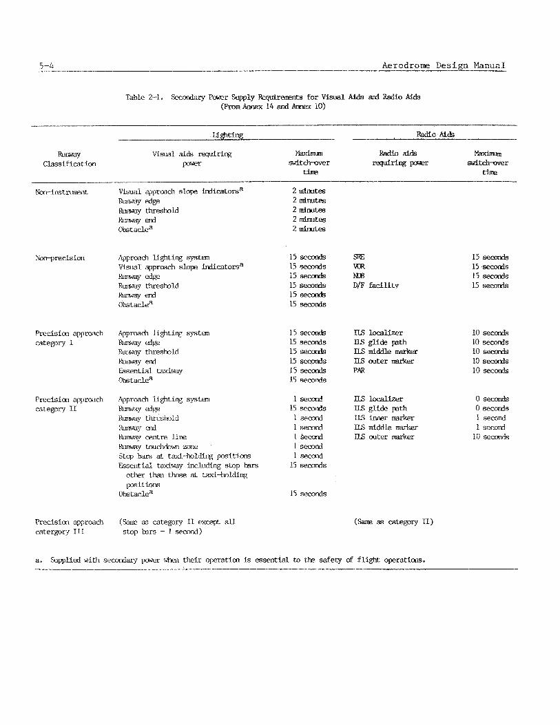
Table 2-1. ry Pawer Supply AidsdRBdioAlds ( b m &X 14 and &X 10)
P-
- WO Aids
C l a s s l f icat ion V i s u a l aids requiring ai
F r r % r t i n e time
Noll-in% trurnent Visual approach slope i d i c a t o r s a W edge RLmway threshold
e d Obstaclea
N o q m c i s i o n Approach Lighting s y s t w Visual approach slope indicatorsa m d g e m y threshold b a y end Obstaclea
Precision approach category I
Approach lighting systan -Y ~~ RLmwq threshold Kurway ad Essential taxiway Obstaclea
Precision approach Approach lighting systan c a t e p r y II -Y &S
Runway t h r e i b l d Rumay erd Ihlmq oentre line Runwrny mchdown zone Stop bars at taxi-holding pcxsitions Esserltial taxiway including stop bars
other than those at taxl-holdiq p i t ions
Obs taclea
Precision approach (%me as category I1 excepl- all c a t e r p r y I11 stop bars - I second)
15 seconds 15 seconds 15 seconds 15 seconds 15 secarads L5 seconds
15 seconds 15 seconds 15 seconds l5 &S
15 sec& 15 secorads
1 second 15 s e d s 1 s e d 1 second l &cord l sfxotki 1 secorad
15 seconds
15 seconds
a. %ppLif?d w i t h s e a m p e r when tlleir operatim is essent ial to tk safety
m m MDB D/F facility
IIS locallzer ILS glide path IIS middle marker ILS outer nrucker PAR
IIS locallzer ILS glide path m Inns ~ ~ l i l l h
ILs middle m outer llm-ka
of f 1igt-s operations.
15 seconds l5 seconds 15 seconds 15 seconds
10 seconds 10 secords 10 seconds 10 secords 10 seconds
0 s e d 0 seconds 1 second 1 second
10 seconds

w i t h i n t h e aerodrome. This power i s u s u a l l y d i s t r i b u t e d by a " p a r a l l e l " sys tem t o t h e v a r i o u s t r ans fo rmer s t a t i o n s f o r f u r t h e r step-down of v o l t a g e t o w t c h t h e i n p u t v o l t a g e of t h e equipment. Two independent incoming e l e c t r i c a l s u p p l i e s t a k e n from wide ly s e p a r a t e d s e c t i o n s of t h e e l e c t r i c i t y network beyond t h e aerodrome a r e recommended. Within t h e aerodrome, r e l i a b i l i t y i n t h e supply of power t o t h e i n d i v i d u a l s t a t i o n s c a n be improved by u s i n g a c l o s e d r i n g h i g h v o l t a g e i n p u t c i r c u i t w i t h ba lanced v o l t a g e p r o t e c t i o n on t h e d i s t r i b u t i o n t r a n s f o r m e r s o r by u s i n g a double l o o p sys tem from independent primary sources o p e r a t i n g a s open r i n g s f e e d i n g two t r a n s f o r m e r s a t each s t a t i o n . This l a t t e r sys tem i s i l l u s t r a t e d i n F igure 2-1. I f a c e n t r a l i z e d moni to r ing sys tem of t h e loop swi tches a t each s t a t i o n and of f a u l t c u r r e n t s l i k e l y t o occur i n each s e c t i o n a r e used p r a c t i c a l l y complete e l i m i n a t i o n of power f a i l u r e s t o t h e t r a n s f o r m e r s t a t i o n s can be achieved. Simpler arrangements p r o v i d i n g l e s s e r r e l i a b i l i t y may be used a t s m a l l e r a i r p o r t s .
2.2 POWER TRANSFER CHARACTERISTIC S
2.2.1 T r a n s f e r (swi tch-over) t ime requ i rements
2.2.1.1 When t h e primary power supply t o t h e more c r i t i c a l v i s u a l a i d s , f a c i l i t i e s , and r a d i o n a v i g a t i o n a i d s f a i l s , t h e l o a d must be t r a n s f e r r e d t o t h e secondary power source . The secondary power source must be s t a r t e d and speed and v o l t a g e s t a b i l i z e d b e f o r e t h e load i s t r a n s f e r r e d .
2.2.1.2 The t r a n s f e r , o r swi tch-over , t imes p e r m i t t e d depend on t h e most c r i t i c a l ins t rument c l a s s i f i c a t i o n of t h e aerodromes opera t ion . Annex 14, Chapter 8, and Annex 10, Volume I, P a r t I , Attachment C l i s t t h e maximum p e r m i s s i b l e t r a n s f e r t i m e s f o r t h e components of aerodrome l i g h t i n g systems and r a d i o a i d s a s s o c i a t e d w i t h non-instrument, n o n - p r e c i s i o n , and p r e c i s i o n approach runway c a t e g o r i e s I , I T , and III; (See Table 2-1. >
Continuous power s o u r c e s
2.2.2.1 C e r t a i n t y p e s of lamps cannot be r e s t a r t e d f o r s e v e r a l minutes i f t h e r e i s a b reak i n t h e c u r r e n t through t h e lamp of more than a few t e n t h s of a second. Some types of r a d i o n a v i g a t i o n and computer d e v i c e s a l low no i n t e r r u p t i o n of power, It i s neces- s a r y t o p rov ide a n u n i n t e r r u p t i b l e o r n e a r cont inuous source of power when t h e primary power s o u r c e f a i l s t o c a t e r t o such equipment. Some d e v i c e s , such a s some computers, a r e capab le of accommodating on ly ve ry l i m i t e d f l u c t u a t i o n s of f requency o r v o l t a g e and r e q u i r e a t r u l y u n i n t e r r u p t i b l e power supply .
2.2.3 Methods of t r a n s f e r
2.2.3.1 The fo l lowing methods a r e suggested a s p o s s i b l e ways t o r e s t o r e t h e power supp ly w i t h i n t h e s p e c i f i e d maximum t r a n s f e r t imes . It i s advantageous t o group l o a d s w i t h s i m i l a r l i m i t i n g t r a n s f e r t imes s o t h a t they may be c o n t r o l l e d a t t h e t r ans fo rmer supply o r a t t h e f e e d e r d i s t r i b u t i o n connect ions from t h e same secondary s o u r c e .
2 ~ i n u t e t r a n s f e r t im. m-ere a 2-minute t r a n s f e r t ime i s p e r m i s s i b l e , - I
l o c a l g a s o l i n e o r d i e s e l engine-generator o r g a s tu rb ine -genera to r s e t s w i t h au tomat ic o r remote s t a r t i n g and s w i t c h i n g are s a t i s f a c t o r y . I n t h i s 2--minute p e r i o d t h e engine o r t u r b i n e can be s t a r t e d and t h e speed and v o l t a g e r e g u l a t i o a can be s t a b i l i z e d .

o L . i g u ~ e C 2-1, Example of a double- loop open-ring i n t e r - m e d i a t e vo l tage d i s t r i b u t i o x network
P a r t 5.- E l e c t r i c a l Systems 5-7
2.3 . t h e majo
b ) 15-second t r a n s f e r t ime. Where a 15-second t r a n s f e r t i m e is r e q u i r e d , s tandby d i e s e l and g a s o l i n e engine-generator s e t s wi th r a p i d - s t a r t c a p a b i l i t y and f a s t - a c t i n g automat ic s w i t c h i n g o r an independent s o u r c e wi th au tomat ic t r a n s f e r swi tch ing can be used.
c ) 10-second t r a n s f e r t ime. Where a 10-second t r a n s f e r t i m e is r e q u i r e d , secondary power u n i t s w i t h s u i t a b l e s t a r t i n g and switch-over c a p a b i l i t y can be used.
d ) One-second t r a n s f e r t ime. Where a one second swi tch-over time i s r e q u i r e d , one of t h e fo l lowing two methods a r e u s u a l l y used f o r t h i s r a p i d t r a n s f e r of power. One method i s t o s t a r t t h e stand-by d i e s e l engine o r gas tu rb ine -genera to r s e t a s soon a s t h e RVR is of the o r d e r of 600 m and o p e r a t e t h e more c r i t i c a l l i g h t i n g and r a d i o a i d s from t h i s g e n e r a t o r s e t wi th au tomat ic t r a n s f e r t o t h e pr imary power source i n c a s e t h e secondary power f a i l s . The c r i t i c a l load power should con t inue t o be f u r n i s h e d by the secondary power source u n t i l an RVR of 800 m i s reached on a f i r m t r e n d of improvements. The second method is t o a u t o m a t i c a l l y switch-over t o a s a t i s f a c t o r y independent power supply.
e ) Near zero t r a n s f e r t ime. Very f a s t - a c t i n g ( s w i t c h i n g i n 0.3 second o r l e s s ) au tomat ic t r a n s f e r dev ices which can swi tch t h e l o a d from the o p e r a t i n g stand-by g e n e r a t o r t o t h e primary s o u r c e a r e r e q u i r e d f o r l i g h t s us ing some types of d i scharge lamps i n o r d e r t o main ta in t h e d i scharge . Another method of o b t a i n i n g a near-zero t r a n s f e r time is t o u s e an i n e r t i a f lywheel-dr iven genera to r which i s capab le of ma in ta in ing t h e power supply dur ing t h e s t a r t - u p of t h e secondary power source .
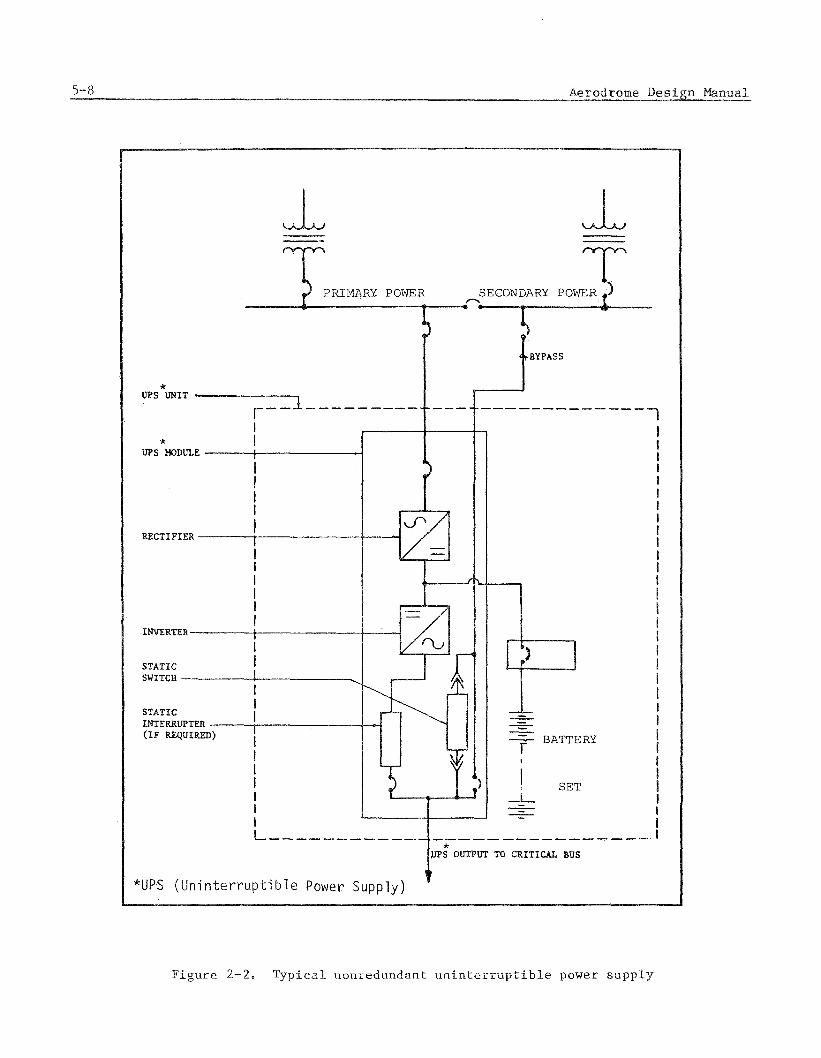
f ) Zero t r a n s f e r t ime. For those f a c i l i t i e s r e q u i r i n g u n i n t e r r u p t i b l e power and a c c e p t i n g on ly l i m i t e d v a r i a t i o n s of v o l t a g e o r f requency, ba t t e ry -d r iven s t a t i c i n v e r t e r ( s ) or g e n e r a t o r ( s ) ( s e e F i g u r e 2-2) may be used. Although t h e secondary power t r a n s f e r should u s u a l l y be accomplished i n on ly s e v e r a l seconds, t h e b a t t e r y s e t ( s ) should be capable of o p e r a t i n g t h e f a c i l i t i e s f o r a minimum of 15 minutes wi thou t recharging.
2.3 SECONDARY POWER EQUIPMENT
Component S
1.1 Secondary e l e c t r i c a l power should be of such q u a l i t y t h a t it w i l l p rov ide r e l i a b i l i t y , a v a i l a b i l i t y , and v o l t a g e s and f r e q u e n c i e s needed by t h e f a c i l i t y . The r i t ems of secondary power equipment commonly used f o r aerodrome l i g h t i n g and r a d i o
n a v i g a t i o n a i d s a r e engine-generator s e t s , power-transfer s w i t c h i n g d e v i c e s , b a t t e r i e s , and b a t t e r y chargers t o f u r n i s h power f o r s t a r c i n g t h e eng ine g e n e r a t o r s , and v a u l t s o r s h e l t e r s f o r t h i s equipment. Less o f t e n used, u s u a l l y f o r s p e c i a l f a c i l i t i e s , a r e u n i n t e r r u p t i b l e power (UPS) sys tems, s tandby battery-power sys tems , s o l a r o r wind g e n e r a t o r s wi th b a t t e r y systems, independent g e n e r a t i n g dev ices such a s t h e s m e l e c t r l c , n u c l e a r , o r f u e l c e l l s . The secondary power equipment should be l o c a t e d as c l o s e a s i s p r a c t i c a l t o t h e inpu t of the f a e i l i t h e a served.
--
UPS MODULE
I I I I l I I
STATIC
P S OUTPUT TO mITICAL BUS
*UPS ( U n i n t e r r u p t i b l e Power Supply)
-. r l g u r e 2-2, T y p i c a l n o n r e d u n d a n t uninterruptibfe power s u p p l y

2.3,2.1 The b a s i c secondary power eng ine -genera to r s e t c o n s i s t s of a prime mover, a g e n e r a t o r o r a l t e r n a t o r , a s t a r t i n g d e v i c e , s t a r t i n g c o n t r o l s , and a f u e l t a n k o r supply . Engine-generator s e t s f o r secondary power u n i t s a r e u s u a l l y i n 100 t o 500 ki lovol t -amperes c a p a c i t i e s but may range from 50 t o 1 000 ki lovol t -amperes i n c a p a c i t y .
a ) Prime movers. The prime movers f o r most secondary power u n i t s a r e g a s o l i n e , d i e s e l , o r gas eng ines o r t u r b i n e s , t h e cho ice b e i n g based on c o s t and a v a i l a b i l i t y of f u e l s . These prime movers a r e u s u a l l y a v a i l a b l e i n s t a n d a r d i z e d s i z e s w i t h adequate power t o h a n d l e t h e k i lovol t -ampere r a t i n g of t h e g e n e r a t o r . The prime movers f o r most major aerodromes a r e r a p i d - s t a r t types which can s t a r t a u t o m a t i c a l l y , s t a b i l i z e t h e speed , and be connected t o t h e l o a d w i t h i n 10 seconds .
b ) Generators . The g e n e r a t o r , u s u a l l y a n a l t e r n a t o r , i s mechan ica l ly coupled t o t h e prime mover and p rov ides secondary e l e c t r i c a l power a t t h e f requency, v o l t a g e , and power r a t i n g of t h e u n i t . These g e n e r a t o r s may be e i t h e r s i n g l e phase o r t h r e e phase. They should have h i g h e f f i c i e n c y i n c o n v e r t i n g mechanical energy t o e l e c t r i c a l ene rgy .
c ) S t a r t i n g dev ices . Most secondary power e n g i n e - g e n e r a t o r sets u s e b a t t e r y packs t o s t o r e energy f o r s t a r t i n g . Because of t h e i n f r e q u e n t u s e , s h o r t o p e r a t i n g p e r i o d s , h i g h s t a r t i n g c u r r e n t demands, and c o s t , lead-acid t y p e b a t t e r i e s a r e used most f r e q u e n t l y f o r s t a r t i n g t h e s e u n i t s . The b a t t e r y pack ( o f t e n a s e t of b a t t e r i e s connected i n s e r i e s and /o r p a r a l l e l ) must be capable of p rov id ing t h e v o l t a g e and c u r r e n t needed t o s t a r t t h e eng ine w i t h i n t h e r e q u i r e d t ime l i m i t s and under t h e most s e v e r e c o n d i t i o n s ( u s u a l l y a low tempera tu re of -7°C) a t which t h e secondary power u n l t i s expected t o o p e r a t e . A b a t t e r y c h a r g e r w i t h over -cur ren t and over-charge c o n t r o l i s permanently connected t o t h e e l c t r i c a l power t o main ta in t h e s t o r e d energy i n t h e b a t t e r i e s . The b a t t e r y pack should b e w e l l v e n t i l a t e d t o p reven t accumula t ion of hydrogen gas and shou ld be p r o t e c t e d from a r c s , s p a r k s , o r f lames which could cause a n exp los ion of any accumulated gas . Nickel-cadmium b a t t e r i e s may be used where s p e c i a l c o n d i t i o n s war ran t t h e i r h i g h i n i t i a l c o s t . Flywheels, pneumatic-pressure v e s s e l s , o the r - than-ba t t e ry s to red-energy dev ices a r e used i n f r e q u e n t l y f o r eng ine s t a r t i n g because of u n r e l i a b i l i t y o r c o s t .
d ) S t a r t i n g c o n t r o l s . The c o n t r o l s f o r t h e eng ine -genera to r s e t a r e u s u a l l y au tomat ic s t a r t w i t h t h e s e n s o r f o r primary power f a i l u r e a s p a r t of t h e t r a n f e r swi tch ing dev ice . Manual o r remote c o n t r o l s a r e sometimes used f o r f a c i l i t i e s w i t h low c r i t i c a l r equ i rements . Once i t i s s t a r t e d , speed and power a r e a u t o m a t i c a l l y r e g u l a t e d by t h e engine and t h e e l e c t r i c a l load i s connected by t h e t r a n s f e r s w i t c h . The eng ine g e n e r a t o r should o p e r a t e a u t o m a t i c a l l y wi thou t adjus tment o r o t h e r a t t e n t i o n . T r a n s f e r of power back t o t h e primary s o u r c e and s topp ing t h e eng ine may be au tomat ic o r by remote c o n t r o l .
e 1 . Liquid f u e l f o r secondary power i s u s u a l l y s t o r e d i n t a n k s n e a r t h e eng ine g e n e r a t o r l o c a t i o n . The c a p a c i t y of t h e f u e l t anks should be adequa te f o r t he m a x i m u m o p e r a t i n g t ime expected of t h e
eng ine-genera to r . Some a u t h o r i t i e s r e q u i r e a minimum of 72 h o u r s supply . Others d e s i g n f o r a l e s s e r t ime p e r i o d , but t h e t i m e pe r iod u s u a l l y should be a t l e a s t twice t h e maximum d u r a t i o n expec ted of c o n d i t i o n s t h a t could r e q u i r e t h e use of secondary power. F u e l t anks and connect ions should meet a l l s a f e t y requirements and s h o u l d p rov ide convenient a c c e s s f o r r e f u e l l i n g . These t a n k s should a l s o p rov ide arrangements f o r t e s t i n g f o r contaminat ion of t h e f u e l , e s p e c i a l l y t h e accumulation of wa te r i n t h e tank.
Power t r a n s f e r s w i t c h i n g
2.3.3.1 A s u i t a b l e t r a n s f e r dev ice i s needed f o r t r a n s f e r r i n g power f rom t h e primary s o u r c e t o t h e secondary source . For manual s t a r t i n g and c o n t r o l t h i s may be a s imple swi tch o r r e l a y t h a t d i s c o n n e c t s t h e load from one power s o u r c e and connec t s i t t o t h e o t h e r . A d d i t i o n a l c o n t r o l s a r e needed f o r au tomat ic t r a n s f e r . These a r e u s u a l l y combined i n t o a s i n g l e c o n t r o l u n i t o r c u b i c l e . Such a u n i t shou ld be c a p a b l e of s e n s i n g t h e f a i l u r e of primary power, i n i t i a t i n g t h e s t a r t i n g of t h e prime mover of t h e secondary g e n e r a t o r s e t , de te rmin ing t h a t t h e v o l t a g e and f requency of t h e g e n e r a t o r have s t a b i l i z e d adequa te ly , and connect ing t h e l o a d t o t h e g e n e r a t o r . Th i s u n i t may a l s o d i sconnec t n o n - e s s e n t i a l l o a d s and f a c i l i t i e s which a r e n o t t o be e n e r g i z e d by t h e secondary source and t r a n s f e r t h e s e l o a d s back t o t h e primary source a f t e r t h a t power has been r e s t o r e d . The swi tches o r r e l a y s f o r d i s c o n n e c t i n g and connec t ing t h e l o a d should have t h e c a p a c i t y t o hand le t h e r a t e d l o a d of t h e g e n e r a t o r . The f u n c t i o n i n g of t h e s e s w i t c h e s o r r e l a y s i s s i m i l a r f o r e i t h e r 2 a r i n u t e , 1 5 s e c o n d , o r l s e c o n d t r a n s f e r t imes , a l though more rap id -ac t ing r e l a y s may be needed f o r t h e s h o r t e s t t r a n s f e r t ime. For a 2-minute t r a n s f e r , t h e power f a i l u r e s e n s o r s may d e l a y a few seconds i n d e t e r - mining i f t h e primary power h a s f a i l e d o r i s on ly f l u c t u a t i n g and a l s o t o de te rmine i f t h e secondary power has s t a b i l i z e d . For a 1 5 s e c o n d t r a n s f e r , t h e s e n s o r s must respond i n l e s s than 3 seconds each because t h e qu ick s t a r t i n g eng ines need 10 seconds t o s t a r t and t o s t a b i l i z e . For t r a n s f e r t imes of 1 second o r l e s s , t ime i s t o o s h o r t t o s t a r t t h e eng ine , bu t t h e load can be swi tched from one power source t o a n o t h e r o p e r a t i n g source w i r h i n t h i s t ime l i m i t ; however, t h e power f a i l u r e s e n s o r ~ a s t r e s p ~ n d withdn a few c y c l e s .
2.3.4 U n i n t e r r u p t i b l e power s u p p l i e s (UPS) systems
2.3.4.1 An u n i n t e r r u p t i b l e e l e c t r i c power supply i s n e c e s s a r y f o r e l e c t r o n i c o r o t h e r equipment t h a t performs a c r i t i c a l f u n c t i o n and r e q u i r e s con t inuous , d i s t u r b a n c e - f r e e e l e c t r i c power t o o p e r a t e p roper ly .
2.3.4.2 UPS equipment. The u n i n t e r r u p t i b l e power supp ly (UPS) sys tem c o n s i s t s of one o r more UPS modules, a n energy-s torage b a t t e r y , and a c c e s s o r i e s a s r e q u i r e d t o p rov ide a r e l i a b l e arid h i g h q u a l i t y power supply . The UPS sys tem i s o l a t e s t h e l o a d from t h e primary and secondary s o u r c e s and i n t h e event of a power i n t e r r u p t i o n p r o v i d e s r e g u l a t e d power t o t h e c r i t i c a l load f o r a s p e c i f i e d pe r iod . (The b a t t e r y t y p i c a l l y has a 15-minute c a p a c i t y when o p e r a t i n g a t f u l l load.) (See F igure 2-2.)
a ) UPS module. A UPS module i s t h e s t a t i c power convers ion p o r t i o n of t h e UPS system and c o n s i s t s of a r e c t i f i e r , an i n v e r t e r , and a s s o d a t e d c o n t r o l s a long w i t h s y n c h r o ~ ~ i z i n g , p r o t e c t i v e , and a u x i l i a r y d e v i c e s . UPS modules may be des igned t o o p e r a t e e i t h e r i n d i v i d u a l l y o r i n p a r a l l e l .

b A nonredundant UPS s y s t e m i s s u i t a b l e f o r most o p e r a t i o n s . However, i f t h e expense i s j u s t i f i e d , a r edundan t UPS c o n f i g u r a t i o n ( s e e F i g u r e 2-3) may be used t o p r o t e c t a g a i n s t module f a i l u r e o r v e r y f r e q u e n t p r imary power f a i l u r e s .
c > The b a t t e r y s h o u l d be a heavy-duty i n d u s t r i a l u n i t of t h e lead-cadmium t y p e hav ing a n ampere-hour r a t i n g s u f f i c i e n t t o s u p p l y d i r e c t c u r r e n t t o t h e i n v e r t e r as r e q u i r e d by t h e UPS s y s t e m m a n u f a c t u r e r ' s i n s t a l l a t i o n i n s t r u c t i o n s . The b a t t e r y i s u s u a l l y f u r n i s h e d w i t h two- t i e r r a c k s ; however, where s p a c e i s l i m i t e d t h r e e - t i e r r a c k s may be n e c e s s a r y .
d ) Remote a l a rms . The UPS equipment s h o u l d be s u p p l i e d w i t h a remote-alarm p a n e l t o be i n s t a l l e d i n t h e o p e r a t i n g s p a c e s e r v e d by t h e UPS u n i t o r i n a n o t h e r c o n t i n u o u s l y occup ied room, s u c h as a gua rd o f f i c e . S ince UPS equipment rooms a r e u s u a l l y una t t ended , a d d i t i o n a l r emote i n d i c a t i n g d e v i c e s s h o u l d be p rov ided t o mon i to r t h e e n v i r o n m e n t a l c o n t r o l and f i r e a l a r m sys t em o f UPS module and b a t t e r y rooms.
e ) UPS and b a t t e r y room r e q u i r e m e n t s . The UPS modules and t h e i r a s s o c i a t e d b a t t e r y set s h o u l d be i n s t a l l e d i n s e p a r a t e rooms. C o n s t r u c t i o n s h o u l d be of a permanent t ype . The w a l l s e p a r a t i n g t h e UPS module room f rom t h e b a t t e r y room s h o u l d be f i r e p r o o f ( l -hour r a t i n g ) . When f e a s i b l e , s p a c e s h o u l d be p rov ided i n t h e UPS module and b a t t e r y rooms f o r t h e a d d i t i o n o f f u t u r e UPS equipment.
f ) Envi ronmenta l c o n t r o l . Both t h e UPS module and b a t t e r y rooms s h o u l d b e p rov ided w i t h a n env i ronmen ta l c o n t r o l s y s t e m t o m a i n t a i n t h e p r e s c r i b e d room c o n d i t i o n s . Each env i ronmen ta l c o n t r o l sys t em s h o u l d c o n s i s t of a p r imary sys t em w i t h a s econda ry sys t em c a p a b i l i t y . Upon f a i l u r e of t h e pr imary e n v i r o n m e n t a l c o n t r o l sys t em, a u t o m a t i c t r a n s f e r t o t h e secsnd- a r y systern s h o u l d o c c u r and shou ld sound a n a l a r m i n d i c a t i n g t h e need f o r main tenance .
2.3.5.1 Other s econda ry power d e v i c e s which may be u s e d f o r s p e c i a l f a c i l i t i e s a r e s t a n d b y b a t t e r y power sys t ems , w i t h o r w i t h o u t d c t o a c i n v e r t e r s ; p h o t o v o l t a i c o r wind g e n e r a t o r s w i t h b a t t e r y sys tems and w i t h o r w i thou t d c t o a c i n v e r t e r s ; i n d e p e n d e n t g e n e r a t i n g d e v i c e s , such as t h e r m o e l e c t r i c , n u c l e a r , o r chemica l f u e l c e l l s ; and i n e r t i a - f l y w h e e l g e n e r a t o r s . The m a n u f a c t u r e r ' s i n f o r m a t i o n shou ld e x p l a i n t h e f u n c t i o n i n g and i n s t a l l a t i o n s f o r u s i n g t h e s e d e v i c e s .
2.4 VAULTS A N D SHELTEKS F O K ELECTRICAL EQUIPMENT
2.4.1 S h e l t e r s
2.4.1.1 Host e l e c t r i c a l equipment f o r a i r p o r t L i g h t i n g and o t h e r f a c i l i t i e s i s l o c a t e d i n v a u i c s o r s p e c i a i s h e l t e r s f o r p r o t e c t i o n f rom t h e wea the r and f o r b e t t e r s e c u r i t y . S u b s t a t i o n s f o r h i g h v o l t a g e a r e u s u a l l y o u t d o o r s , and medium v o l t a g e d i s t r i h ~ f i o n t r a n s f o r m e r % a r e o f t e n p o l e mounted o r p l a c e d o n f enced t r a n s f o r m e r pads. Host e l e c t r i c a l v a u l t s & r e above ground aad made of f i r e ~ r o ~ f materials. P e i n f o r c e d

5-1 2 Aerodrome Des inn I?lanual
UPS MODULE NO. 2 UPS NoDVLE m.1
BATTERY PACK
NONAUTOMATIC CIRCUIT BREAKER
UPS OUTPUT T CRITICAL BUS
F i g u r e 2-3- i y p i c a i dP5 stana-by r edunnan t c o n f i g u r a t i o n
c o n c r e t e f o r t h e f l o o r s and c o n c r e t e , c o n c r e t e o r c i n d e r b lock , a n d / o r b r i c k f o r t h e w a l l s a r e m a t e r i a l s commonly used i n t h e s e v a u l t s . The use of such m a t e r i a l s reduce t h e hazard of e l e c t r i c shock, s h o r t i n g of e l e c t r i c a l c i r c u i t s , and f i r e h a z a r d s . P r e f a b r i - c a t e d meta l s t r u c t u r e s a r e o c c a s i o n a l l y used a s s h e l t e r s f o r t r a n s f o r m e r s and engine- g e n e r a t o r s e t s . These v a u l t s a r e used t o house t h e power d i s t r i b u t i o n and c o n t r o l equipment, secondary power equipment, and t h e v a r i o u s d e v i c e s used t o p rov ide power and c o n t r o l f o r t h e a i r p o r t l i g h t i n g sys tems. These v a u l t s shou ld be of a d e q u a t e s i z e t o c o n t a i n t h e necessa ry equipment wi thou t crowding. These v a u l t s may be d i v i d e d i n t o rooms f o r b e t t e r s e g r e g a t i o n of equipment and a c t i v i t i e s .
2.4.2 Locat ion
2.4.2.1 E l e c t r i c a l v a u l t s shou ld n o t be l o c a t e d where they would i n f r i n g e on o b s t a - c l e l i m i t a t i o n s u r f a c e s . The d i s t a n c e s from t h e c o n t r o l tower t o t h e v a u l t s should be s h o r t enough t o avoid e x c e s s i v e v o l t a g e drop i n t h e c o n t r o l c a b l e s . The p e r m i s s i b l e l e n g t h of t h e s e c a b l e s v a r i e s w i t h t h e s i z e of t h e c a b l e , t h e c o n t r o l v o l t a g e , and t h e t y p e s of c o n t r o l r e l a y s used, bu t some of t h e l o n g e r c o n t r o l systems l i m i t t h e l e n g t h of c o n t r o l c a b l e s t o about 2 250 metres . Vehicular a c c e s s t o t h e v a u l t s i n a l l types of weather c o n d i t i o n s i s necessa ry and minimum c o n f l i c t w i t h a i r c r a f t t r a f f i c i s d e s i r a b l e . The l o c a t i o n should be convenient f o r connec t ing t o t h e a p p r o p r i a t e l i g h t i n g c i r c u i t s and f a c i l i t i e s t o keep f e e d e r c a b l e l e n g t h s a s s h o r t a s i s p r a c t i c a l . The v a u l t s shou ld be i s o l a t e d from o t h e r b u i l d i n g s and f a c i l i t i e s t o p reven t t h e s p r e a d of f i r e s o r e x p l o s i o n s , except t h e s h e l t e r s f o r secondary eng ine -genera to r s e t s may be n e a r t h e e l e c t r i c a l v a u l t t o reduce c a b l e l e n g t h and s i z e and t o s i m p l i f y t h e power t r a n s f e r system. Aerodromes w i t h approach l i g h t i n g systems may need s e p a r a t e approach l i g h t i n g v a u l t s f o r each approach l i g h t i n g system. For major aerodromes, some a u t h o r i t i e s use a v a u l t n e a r each end of t h e runway o r approach l i g h t i n g sys tem t o more e a s i l y a r r a n g e f o r i n t e r l e a v i n g of t h e l i g h t i n g c i r c u i t s and t o improve i n t e g r i t y of t h e sys tems.
2.4.3 S p e c i a l p r o v i s i o n s
2 = 4 + 3 . 1 A s s p e c i a l purpose b u i l d i n g s , e l e c t r i c a l v a u l t s may r e q u i r e s p e c i a l f e a t u r e s t o p rov ide s a f e t y and r e l i a b l e performance of t h e equipment. Some of t h e s e f e a t u r e s a r e a s fo l lows :
a ) V e n t i l a t i o n . Provide adequate v e n t i l a t i o n t o p r e v e n t t r a n s f o r m e r t empera tu res exceeding t h e v a l u e s p r e s c r i b e d by t h e manufacture. Most of t h e e l e c t r i c a l h e a t l o s s e s must be removed by v e n t i l a t i o n ; on ly a minor p a r t can be d i s s i p a t e d by t h e v a u l t w a l l s . Some e l e c t r i c a l codes recommend 20 s q u a r e c e n t i m e t r e s of c l e a r g r a t i n g a r e a p e r k i l o v o l t - ampere of t r ans fo rmer c a p a c i t y . In l o c a l i t i e s w i t h above-average t empera tu res , such a s t r o p i c a l o r s u b t r o p i c a l a r e a s , t h e g r a t i n g a r e a should be i n c r e a s e d o r supplemented by f o r c e d v e n t i l a t i o n .
b ) Access. Adequate a c c e s s should be provided f o r r e p a i r s , maintenance, i n s t a l l a t i o n , and removal of equipment.
c ) Drainage. A l l v a u l t s shou ld be provided w i t h d ra inage . When normal d r a i n a g e i s n o t p o s s i b l e , provide a sump p i t t o pe rmi t t h e u s e of a p o r t a b l e pump.
d j S e c u r i t y . Each e l e c ~ r i c a l v a u i c shou ld b e equipped t o d e t e r i n a d v e r t e n t o r premedi ta ted a c c e s s by unauthor ized pe r sons . Th i s s e c u r i t y i s necessa ry t o p reven t i n t e r f e r e n c e w i t h equipmeat o p e r a t i o n and t o p r o t s c t t h o s s persGns f r o m p ~ s s i b l e e l e c t r i c s h ~ c k . Some rnerhods used

a r e ba r red and sc reened windows, heavy-duty meta l doors w i t h pad locks , and s e c u r i t y fencing.
e > . E l e c t r i c a l v a u l t s should be w e l l i l l u m i n a t e d f o r u s e e i t h e r day o r n i g h t . Th i s l i g h t i n g i s u s u a l l y provided by i n t e r i o r l i g h t s of a s i z e , type , and l o c a t i o n t o p rov ide good v i s i b i l i t y i n a l l a r e a s . Poor v i s i b i l i t y can i n c r e a s e t h e p o t e n t i a l f o r a c c i d e n t s r e s u l t i n g i n e l e c t r i c a l shock o r improper c o n t r o l and a d j u s t m e n t s .
f ) Local communications. Most e l e c t r i c a l v a u l t s should be p rov ided w i t h convenient and r e l i a b l e communications t o t h e c o n t r o l tower , o t h e r v a u l t s , and perhaps o t h e r f a c i l i t i e s o r o f f i c e s . S p e c i a l t e l e p h o n e o r in tercommunicat ion systems may avoid o u t s i d e i n t e r f e r e n c e w i t h t h e s e c i r c u i t s , b u t o t h e r dependable arrangements can be used.
g ) E l e c t r i c a l condu i t s . E l e c t r i c a l v a u l t s shou ld be provided w i t h a s u f f i c i e n t number of c o n d u i t s and c a b l e e n t r a n c e a c c e s s e s t o a v o i d l a t e r m o d i f i c a t i o n of t h e s t r u c t u r e t o permit t h e i n s t a l l a t i o n of a d d i t i o n a l i n p u t o r o u t p u t c i r c u i t s . These c a b l e s e n t r a n c e s a r e u s u a l l y through underground c o n d u i t s which may be connected t o e x i s t i n g c a b l e d u c t s , d i r e c t - b u r i a l c a b l e s , o r unused condu i t s a v a i l a b l e f o r f u t u r e expansion. Unused c o n d u i t s should be plugged, and c o n d u i t s w i t h c a b l e s shou ld be s e a l e d .
h) I n s t a l l a t i o n s of equipment. Arrange t h e equipment, e s p e c i a l l y t h e l a r g e r i t ems such a s r e g u l a t o r s , d i s t r i b u t i o n t r a n s f o r m e r s , c o n t r o l p a n e l s , and c i r c u i t s e l e c t o r o r c o n t r o l d e v i c e s , t o p rov ide a s imple , u n c l u t t e r e d , uncrowded plan. This arrangement should c o n s i d e r s a f e t y , e s p e c i a l l y p r o t e c t i o n from h i g h v o l t a g e e l e c t r i c a l c o n n e c t i o n s , a s w e l l a s a c c e s s t o t h e equipment and c o n t r o l s . The e l e c t r i c a l c i r c u i t s should a i s o be a r ranged i n a s imple p a t t e r n wherever p o s s i b l e . Follow t h e a p p l i c a b l e e l e c t r i c s a f e t y codes f o r i n s t a l l i n g a l l e l e c t r i c a l c i r c u i t s and c o n t r o l s .
2.5 DISTRIBUTION OF POWER
2.5.1 General
2.5.1.1 The equipment d i s c u s s e d i n t h i s s e c t i o n r e l a t e s o n l y t o t h a t used i n t r a n s m i t t i n g e l e c t r i c a l power f o r t h e aerodrome l i g h t i n g and r a d i o n a v i g a t i o n a i d s between t h e main aerodrome s u b s t a t i o n ( s ) and t h e l i g h t i n g v a u l t s o r t h e l o c a l s i t e d i s t r i b u t i o n t r ans fo rmers . Desc r ip t ions of equipment a r e i n g e n e r a l terms o f c h a r a c t e r - i s t i c s and needs and u s u a l l y a r e n o t r e l a t e d t o s p e c i f i c t y p e s o r i tems of equipments . Types of equipment and number of d e v i c e s w i l l vary g r e a t l y w i t h t h e s i z e and complexi ty of t h e aerodrome. Economics i s an important p a r t of i n s t a l l a t i o n s , and on ly equipment which c o n t r i b u t e s t o performance, s a f e t y , r e l i a b i l i t y , and i n t e g r i t y shou ld be used. The c i r c u i t s and equipment used should p rov ide f o r a r easonab le expansion of f a c i l i t i e s w E f f i c i e n t u s e of e l e c t r i c a l power is always a d e s i r a b l e goa l , bu t t h e power c o s t f o r aerodrome l i g h t i n g and r a d i o navigation a i d s i s u s u a l l y a r a t h e r s m a i i p a r t o f t h e t o t a l aerodrome energy c o s t and should n o t be emphasized t o t h e p o i n t of o v e r l y i n c r e a s i n g l r i s t a l l a t i o n c o s t s 01- of d imin i sh ing performa~lce , s a f e t y , o r r e l i a b l l i t y i Follow r h e l o c a l e l e c t r i c a l s a f e c y codes.

2.5.2.1 Primary power i s u s u a l l y reduced i n v o l t a g e a t t h e main aerodrome s u b s t a t i o n f o r d i s t r i b u t i o n on t h e aerodrome. For major aerodromes, t h i s power a t t h e f i r s t s t a g e may be a t a n i n t e r m e d i a t e v o l t a g e ( u s u a l l y 5 000 t o 20 000 v o l t s ) , b u t f o r s m a l l e r , l e s s complex aerodromes, t h i s power may be d i s t r i b u t e d a t a medium v o l t a g e ( u s u a l l y 1 000 t o 5 000 v o l t s ) . The d i s t a n c e and t o t a l l o a d on t h e c i r c u i t a r e impor tan t f a c t o r s i n de te rmin ing t h e v o l t a g e l e v e l of t r ansmiss ion . For a n i n t e r m e d i a t e - v o l t a g e d i s t r i b u t i o n system, power i s o f t e n r u n t o s u b s t a t i o n s n e a r l a r g e power usage a r e a s where i t i s reduced t o medium v o l t a g e f o r l o c a l d i s t r i b u t i o n . A combination of t h e s e v o l t a g e d i s t r i b u t i o n systems may be used. Primary power i s t r a n s m i t t e d from t h e main s u b s t a t i o n t o t h e l o c a l s u b s t a t i o n o r d i s t r i b u t i o n s i t e s u s u a l l y as multi-phase c i r c u i t s by above ground (overhead) c i r c u i t s , underground c i r c u i t s , o r a combination of t h e s e c i r c u i t s . Above ground c i r c u i t s a r e l e s s expensive t o i n s t a l l and a r e u s u a l l y used i f f e a s i b l e , but t h e s e c i r c u i t s may be more exposed t o damage and i n some a r e a s a r e a haza rd t o a i r c r a f t and c r e a t e e l e c t r o m a g n e t i c i n t e r f e r e n c e f o r o t h e r equipment. Underground f e e d e r c a b l e s a r e u s u a l l y i n s t a l l e d i n d u c t s , b u t sometimes d i r e c t b u r i a l i s used. Each t y p e of c i r c u i t , whether overhead o r underground, i n v o l v e s s p e c i f i c t y p e s of equipment and des ign .
2.5.3 Above-ground (overhead) primary d i s t r i b u t i o n systems
2.5.3.1 The fo l lowing f a c t o r s shou ld be cons ide red i n t h e d e s i g n of a n overhead power d i s t r i b u t i o n system:
a ) Appl ica t ion . Use overhead d i s t r i b u t i o n i n l i e u of underground d i s t r i b u - t i o n wherever f e a s i b l e .
b ) Capaci ty . Provide f o r s p a r e c a p a c i t y i n each p o r t i o n of t h e c i r c u i t . Peak l o a d s do n o t r e l a t e d i r e c t l y t o s p a r e c a p a c i t y .
c ) Wire s i z e . S e l e c t t h e w i r e s i z e i n accordance wi th t h e c u r r e n t - c a r r y i n g c a p a c i t y r e q u i r e d and, where a p p l i c a b l e , t h e vol tage-drop l i m i t a t i o n .
2.5.4 L i n e v o l t a g e r e g u l a t o r s
2.5.4.1 Regula tors a r e used f o r c o r r e c t i o n of 1 i n e v o Z t a g e v a r i a t i o n s r e s u l t i n g f rom changing l o a d s o r u t i l i t y company i n p u t v o l t a g e changes. Do n o t u s e t h e s e r e g u l a t o r s t o c o r r e c t f o r e x c e s s i v e v o l t a g e d rops . Booster t r a n s f o r m e r s which c o r r e c t f o r v o l t a g e drop should be used on ly i n r a r e i n s t a n c e s a s , i n most c a s e s , c o r r e c t d e s i g n e l i m i n a t e s e x c e s s i v e v o l t a g e drop.
a ) Rating. Choose t h e r a t i n g of t h e r e g u l a t i n g d e v i c e s i n accordance w i t h t h e amount of r ebwla t ion requ i red .
b ) S e l e c t i o n . Choose t h e t y p e of r e g u l a t o r s from f i x e d c a p a c i t o r s , swi tched c a p a c i t o r s , m u l t i s t e p (motor-driven t a p changing) r e g u l a t o r s , and i n d u c t i o n ( s t e p l e s s v o l t a g e change) r e g u l a t o r s .
c ) M u l t i s t e p o r i n d u c t i o n r e g u l a t o r s . Provide l i n e d r o p compensation f o r a u t o m a t i c o p e r a t i o n when t h e s e r e g u l a t o r s a r e used on more than one source o r when more t h a n one r e g u l a t o r i s used on a s i n g l e c i r c u i t .

Power l i n e s
2.5.5.1 S e l e c t t h e type of power l i n e s i n accordance wi th t h e type of c i r c u i t invo lved and t h e c o n d i t i o n s t o which i t is s u b j e c t e d from t h e fo l lowing :
a ) Open w i r e (ba re o r wea the rproof ) on i n s u l a t o r s .
b ) A e r i a l c a b l e , s e l f s u p p o r t e d o r suppor ted by a h i g h s t r e n g t h s t e e l (messenger) c a b l e , c o n s i s t i n g of i n s u l a t e d , bundled, s ing le -conduc to r c a b l e o r mul t ip le -conduc to r cab le .
Poles. Wood, c o n c r e t e ( r e i n f o r c e d w i t h p r e s t r e s s i n g o r p o s t a ) P
t e n s i o n i n g ) , o r me ta l ( s t e e l o r aluminum) may be used. Concre te or meta l p o l e s shou ld be used o n l y where they a r e more economical o r s p e c i a l c o n s i d e r a t i o n s w a r r a n t t h e i r use .
b ) Foot ings . Provide f o o t i n g s , o r r e in fo rcements of t h e p o l e b u t t - e n d , a s r e q u i r e d by founda t ion c o n d i t i o n s .
c ) Conf igura t ion . Armless c o n s t r u c t i o n f o r a e r i a l l i n e s i s u s u a l l y l e s s c o s t l y than crossarm c o n s t r u c t i o n and i t s u s e i s p r e f e r r e d , as i s mul t i - corlductor secondary c a b l e w i t h a l a r g e n e u t r a l conductor a s t h e suppor t - i n g member over i n d i v i d u a l suppor ted conductors . Use c rossa rms mainly f o r equipment suppor t .
d ) Guys and anchors . Provide guys and anchors t o s u p p o r t p o l e s o r l i n e towers a g a i n s t h o r i z o n t a l unbalanced l o a d s caused by a n g l e s , c o r n e r s , and t e rmina t ions of l i n e s and where r e q u i r e d because of ex t reme wind load ings . Consul t manufac tu re r s7 c a t a l o g u e s f o r t y p e s of eareh anchors and d e s i g n d a t a . S e l e c t equipment s u i t a b l e f o r t h e p a r t i c u l a r s o i l c o n d i t i o n s and t h e c o n s t r u c t i o n m t h o d t o be used.
2.5.6 Conductors
2.5.6.1 S i z e l i m i t a t i o n s . Limit t h e u s e of p o l e - l i n e conductors i n accordance w i t h Table 2-2 f o r an econom%cal sys tem from t h e i n s t a l l a t i o n , o p e r a t i o n a l , and maintenance p o i n t s of view. S p e c i a l i r l s t ances may r e q u i r e l a r g e r conductors . In a l l i n s t a n c e s be s u r e t h a t t h e type and s i z e of conductors used p rov ides adequa te s t r e n g t h f o r t h e span l e n g t h s and load ing c o n d i t i o n s .
Table 2-2
Conductor t y p e

2.5.6.2 Base w i r e s i z e on t h e ranges shown i n Table 2-2. Primary w i r e s i z e s u s u a l l y should n o t be l e s s than 13.0 mm2 copper o r 33.0 mm2 aluminum. For primary conduc to r s , s e l e c t from t h e fo l lowing :
a ) Bare copper conduc to r , s t r a n d e d o r s o l i d copper.
b ) Bare aluminum-alloy conduc to r , s t r a n d e d o r s o l i d aluminum-alloy.
c ) Bare aluminum conduc to r , s t e e l r e i n f o r c e d .
d ) Bare h i g h s t r e n g t h all-aluminum a l l o y conductor .
2.5.6.3 S p e c i a l conductors . In s p e c i a l i n s t a n c e s , u s e of t h e f o l l o w i n g conduc to r s may be a p p r o p r i a t e f o r primary conductors :
a ) I n s u l a t e d conduc to r , copper o r aluminum, preassembled n o n - m e t a l l i c - shea thed o r me ta l l i c - shea thed , s tee l -cable-suppor ted (messenger- s u p p o r t e d ) a e r i a l c a b l e i s used where necessa ry t o avo id exposure t o open w i r e haza rds , f o r example, h igh r e l i a b i l i t y s e r v i c e i n heavy s to rm a r e a s .
b ) Compound conductor m a t e r i a l s such a s copper-clad s t e e l , aluminum-clad s t e e l , ga lvan ized s t e e l , o r bronze a r e used t o p rov ide h i g h s t r e n g t h and c o r r o s i o n r e s i s t a n c e .
2.5.6.4 D i s s i m i l a r conductors . Where i t i s necessa ry t o connect aluminum conduc to r s t o copper conductors , a p p r o p r i a t e connec to r s s p e c i f i c a l l y des igned f o r such u s e should be i n s t a l l e d i n accordance w i t h t h e i n s t r u c t i o n s of t h e manufacturer .
2.5.7 I n s u l a t o r s
2 ,5 ,7 ,1 Types of i n s u l a t o r s - Select from t h e f o l l o w i n g l i s t t h e t y p e of i n s u l a t o r t o suppor t b a r e o r weatherproof i n s u l a t e d conductors .
a ) Suspension t y p e , s i n g l e o r m u l t i p l e .
b ) Spool type .
c ) Line-post t y p e (one-piece p o r c e l a i n on a b o l t f o r mounting on crossarms o r on a s a d d l e on t h e s i d e of a po le ) .
d ) S t r a i n t y p e (suspension u n i t s w i t h s t r e n g t h e q u a l o r exceed ing t e n s i l e s t r e n g t h of t h e conductor u s u a l l y having one t o t h r e e e x t r a d i s k s e c t i o n s and a r c i n g horns o r r i n g s ) .
e ) Pin type ( p o r c e l a i n , u s u a l l y two o r more s e p a r a t e s h e l l s cemented t o g e t h e r , w i t h a n i n t e r n a l t h r e a d f o r screwing on to a wood o r meta l p i n ) .
f ) Combinations. Various t y p e s of i n s u l a t o r s may be combined; f o r example, s t r a i n t y p e f o r anchor p o l e s o r t e r m i n a t i o n s w i t h e i t h e r p i n o r l i n e - p o s t t y p e s f o r l i n e i n s u l a t i o n . Line-post t y p e s a r e c o n s i d e r e d t o be bo th l e s s expensive and s u p e r i o r t o p i n types .

2.5.7.2 I f overhead l i n e s a r e used i n l o c a t i o n s e n s i t i v e t o e l e c t r o m a g n e t i c i n t e r - f e r e n c e , t h e i n s u l a t o r s shou ld be of a s t a t i c - f r e e type.
2.5.8 Locknuts
2.5.8.1 Hardware components shou ld be provided w i t h l o c k n u t s t o avo id l o o s e connect- i o n s which could cause s t a t i c . Locknuts must be th readed and of a type which w i l l p revent loosen ing of t h e connect ion when wood members s h r i n k .
2.5.9 Transformers
2.5.9.1 Mount t r a n s f o r m e r s on p o l e s o r a t ground l e v e l . When s h e e t me ta l e n c l o s u r e s a r e n o t tamperproof , ground mounted u n i t s shou ld be provided w i t h a f enced enc losure . A c o n c r e t e o r b r i c k s t r u c t u r e shou ld be used where a d v e r s e
-
weather c o n d i t i o n s make such an i n s t a l l a t i o n a d v i s a b l e .
a 1 For s i n g l e - p o l e mounting, l i m i t t h e s i z e o f s ingle-phase o r three-phase u n i t s i n accordance w i t h approved p r a c t i c e s .
b ) Pole-platform mounting. Po le -p la t fo rm mounting (two-pole s t r u c t u r e s ) should n o t be used, excep t i n i n s t a n c e s where o t h e r methods a r e no t s a t i s f a c t o r y . For i n s t a l l a t i o n s of 225 o r 500 k i lovo l t - ampers , pad-mounted compartmental-type t r a n s f o r m e r s become an a t t r a c t i v e economic a l t e r n a t i v e t o pole-mounted u n i t s *
c ) Ground m o u n t i n g For ground mounting on a c o n c r e t e b a s e , t h e r e i s no ki lovol t -ampere l i m i t . Usual ly tamperproof t r a n s f o r m e r s ( c l a s s i f i e d a s gad-mounted compartmental-type u n i t s ) shou ld n o t b e s p e c i f i e d f o r r a t i n g s of over 500 ki lovol t -amperes .
2.5.9.2 Ra t ings . S e l e c t t r a n s f o r m e r s w i t h s t a n d a r d ki lovol t -ampere r a t i n g s and i n p u t and o u t p u t v o l t a g e as single-phase o r three-phase u n i t s , Transformers w i t h i n p u t v o l t a g e t a p s f o r s e l e c t i n g t h e most s u i t a b l e i n p u t v o l t a g e l e v e l may be d e s i r a b l e f o r some i n s t a l l a t i o n s .
2.5.9.3 Indoor i n s t a l l a t i o n s . Oil-immersed (f lammable) t r ans fo rmers shou ld n o t be i n s t a l l e d indoors excep t i n v a u l t s conforming t o t h e requ i rements of t h e a p p l i c a b l e e l e c t r i c code. Such v a u l t s shou ld be provided o n l y when o t h e r t y p e s of t r a n s f o r m e r s a r e l e s s economical o r a r e p r o h i b i t e d by s p e c i a l c o n s i d e r a t i o n s . Where such a v a u l t is not p rov ided , s e l e c t t r ans fo rmers f o r indoor i n s t a l l a t i o n from t h e f o l l o w i n g :
a ) h i g h - f i r e - p o i n t , l iquid-immersed;
b ) dry-type , v e n t i l a t e d ;
c ) dry-type, s e a l e d t a n k ; and
d ) nonhazardous gas - insu la ted .
2.5.9.4 Toxic i n s u l a t i o n f l u i d s . The t r a n s f o r m e r s shou ld n o t u s e p o l y - c h l o r i n a t e d b ipheny l (PCB) o r o t h e r h i g h l y t o x i c i n s u l a t i o n f l u i d s . Leakage o r mishand l ing of t h e s e chemicals dur ing maintenance t e s t i n g can be hazardous t o pe r sonne l .

2.5.10 Capac i to r s
2,5.10.1 Use shun t c a p a c i t o r s t o improve t h e power f a c t o r of t h e load c a r r i e d by t h e c i r c u i t . I n app ly ing c a p a c i t o r s , c o n s i d e r t h e fo l lowing :
a ) Fixed capac i t ance . Fixed c a p a c i t a n c e i s t h e amount of c a p a c i t a n c e t h a t can be a p p l i e d con t inuous ly wi thou t e x c e s s i v e v o l t a g e rise a t reduced load.
b ) Switched capac i t ance . Switched c a p a c i t a n c e i s a n a d d i t i o n a l amount of c a p a c i t a n c e t h a t can be a p p l i e d , i f p r o v i s i o n i s made t o s w i t c h o f f t h i s a d d i t i o n a l amount a t reduced demand.
c ) Capac i to r swi tch ing . S e l e c t a type of c a p a c i t o r s w i t c h i n g t h a t i s s u i t a b l e f o r t h e c o n d i t i o n a t hand. P o s s i b l e cho ices i n c l u d e remote c o n t r o l of t h e c a p a c i t o r s w i t c h i n g d e v i c e , time-clock c o n t r o l , power- f a c t o r r e l a y c o n t r o l o r v o l t a g e - s e n s i t i v e r e l a y c o n t r o l .
2.5.10.2 Locat ion of c a p a c i t o r s . I n s t a l l c a p a c i t o r s i n banks on p o l e s , a t ground l e v e l , o r i n a s u b s t a t i o n a s n e a r l y a s p o s s i b l e t o t h e c e n t r o i d of t h e a r e a where c o r r e c t i o n i s requ i red .
2.5.11 C i r c u i t i n t e r r u p t i o n d e v i c e s
2.5.11.1 Fuses. A f t e r c o n s i d e r a t i o n of t h e necessa ry c u r r e n t - c a r r y i n g c a p a c i t i e s , i n t e r r u p t i n g d u t i e s , and t ime-current m e l t i n g and c l e a r i n g c h a r a c t e r i s t i c s , s e l e c t f u s e s from t h e f o l l o w i n g types :
a ) open f u s i b l e l i n k ;
b ) expu l s ion t y p e ;
c ) bor ic -ac id type ; and
d ) c u r r e n t - l i m i t i n g t y p e .
2.5.11.2 C i r c u i t b reakers . Co-ordinate t h e c i r c u i t b reaker r a t i n g w i t h t h e l o a d i n t e r r u p t i n g du ty and w i t h c i r c u i t b r e a k e r s and f u s e s ahead of o r a f t e r t h e c i r c u i t b reaker .
2.5.11.3 Automatic c i r c u i t r e c l o s e r s . Use of au tomat ic r e c l o s e r s f o r o t h e r than overhead l i n e loads may cause problems from h i g h - r e s i s t a n c e ground f a u l t s . I f an auto- m a t i c c i r c u i t r e c l o s e r i s used, c o n s i d e r t h e r e l i a b i l i t y and c o n t i n u i t y requ i rements of t h e s e r v i c e . Reclosers may c o n s i s t of a c i r c u i t - b r e a k e r o r m u l t i p l e s w i t c h i n g dev ices . Rec lose r s o p e r a t e s o t h a t a f a u l t e d c i r c u i t may be opened and t h e n , e i t h e r i n s t a n t a n e - o u s l y o r w i t h d e l i b e r a t e t ime d e l a y , r ec losed . Up t o t h r e e r e c l o s u r e s w i t h va ry ing t i m e i n t e r v a l s may be used. Co-ordinate au tomat ic c i r c u i t r e c l o s e r s w i t h f u s e s o r c i r c u i t b r e a k e r s on t h e same c i r c u i t .
2.5.11.4 Switches. Use swi tches t o l o c a l i z e d e f e c t i v e p o r t i o n s of a e r i a l and under- ground c i r c u i t s and t o accomplish dead-c i rcu i t work. S e l e c t from one of t h e fo l lowing p r i n c i p a l types :
a ) Nonload-break swi tches . Use nonload-break swi tches on ly f o r t h e i n t e r - t c a r r y no a p p r e c i a b l e load. S e l e c t t h e type
a p p l i c a b l e , depending on c i r c u i t importance , l o a d , v o l t a g e , and f a u l t c i r c u i t du ty . The t y p e s a v a i l a b l e a r e p o r c e l a i n d i s c o n n e c t f u s e c u t o u t s , p l a i n o r f u s e d s i n g l e - p o l e a i r d i sconnec t s w i t c h e s , and d i s c o n n e c t f u s e c u t o u t s of v a r i o u s types . Disconnect ing and horn-gap swi tches may a l s o be used a s nonload-break s w i t c h e s ,
b ) Load-break swi tches . b a d - b r e a k swi tches a r e provided w i t h a n i n t e r - r u p t i n g d e v i c e capab le of d i s c o n n e c t i n g c i r c u i t s under load. Fuse c u t o u t s , which a r e des igned t o be load-break and l o a d - i n t e r r u p t e r s w i t c h e s , are a v a i l a b l e . Vacuum swi tches a l s o provide load-break c a p a b i l i t y .
2.5.12.1 To determine t h e requ i rements f o r l i g h t n i n g p r o t e c t i o n , c o n s i d e r overhead ground w i r e , open o r e x p u l s i o n gaps , and d i s t r i b u t i o n - t y p e s u r g e ( l i g h t n i n g ) a r r e s t e r s . The weather shou ld a l s o be cons ide red . P r o t e c t i o n f o r l ightning- induced s u r g e s may be unnecessary i n a r e a s where annua l l i g h t n i n g s torms a r e few. A d m i n i s t r a t i v e p o l i c y o r l o c a l e l e c t r i c power company p r a c t i c e shou ld u s u a l l y be fo l lowed. S e l e c t t h e p roper a r r e s t e r i n accordance w i t h t h e chosen b a s i c impulse i n s u l a t i o n l e v e l f o r which t h e c i r c u i t must be b u i l t .
2.5.13 Clea rances
2.5.13.1 Provide t h e necessa ry h o r i z o n t a l and v e r t i c a l c l e a r a n c e s f rom a d j a c e n t p h y s i c a l o b j e c t s , such a s b u i l d i n g s , s t r u c t u r e s , and o t h e r e l e c t r i c l i n e s , a s r equ i red by t h e a p p l i c a b l e e l e c t r i c a l s a f e t y code. Provide a g a i n s t cont ingency i n t e r f e r e n c e s , such as broken p o l e s , broken c rossa rms , and broken c i r c u i t conductors . P rov ide f o r c l e a r a n c e c o n d i t i o n s a r i s i n g from mu.ltipurpose j o i n t u s e of p o l e s . !%e t h e a p p l i c a b l e e l e c t r i c a l s a f e t y code f o r c l imbing s p a c e c l e a r a n c e s , j o i n t use , and supply conductor p r o t e c t i o n .
2.5.14 Grounding
2.5.14.1 For in fo rmat ion on grounding of overhead d i s t r i b u t i o n sys tems, u s e t h e a p p l i c a b l e e l e c t r i c a l s a f e t y code o r A d m i n i s t r a t j v e p o l i c y . For s a f e t y p r o v i d e grnund- i n g f o r a l l equipment and s t r u c t u r e s a s s o c i a t e d w i t h e l e c t r i c a l systems t o p r e v e n t shock from s t a t i c o r dynamic v o l t a g e s . Maximum ground r e s i s t a n c e shou ld not exceed va lues s p e c i f i e d i n t h e a p p l i c a b l e e l e c t r i c a l s a f e t y code. Consider t h e source of e l e c t r i c power, c a p a c i t y , magnitude of f a u l t c u r r e n t , and method of sys tem grounding, a s they a f f e c t t h i s r e s i s t a n c e .
2.5.14.2 Ground rods . Ground rods may be used e i t h e r s i n g l y o r i n c l u s t e r s . Drive t h e ground rods t o ground wa te r l e v e l f o r a n e f f e c t i v e and permanent i n s t a l l a t i o n . Provide f o r c o r r o s i o n p reven t ion by a p roper cho ice of m e t a l s o r by c a t h o d i c p r o t e c t i o n . Where ground wa te r cannot be reached, chemicals such a s magnesium s u l p h a t e (MgS04) o r copper s u l p h a t e (CuSO,+) may be used t o improve s o i l c o n d u c t i v i t y where n e c e s s a r y . Manu- f a c t u r e r s of ground rods can p rov ide d a t a on such t r ea tment . Provide f o r e a s y mainte- nance and p e r i o d i c t e s t i n g . Although d r i v i n g ground rods deeper ( s e c t i o n a l t y p e ) may be more e f f e c t i v e than m u l t i p l e r o d s , i n many c a s e s , s o i i v a r i a t i o n s and p o s s i b l e bedrock may make p r o v i s i o n of a d d i t i o n a l r o d s l e s s expensive .

2.5.14.3 A b u r i e d network of ground conductors w i l l a s s u r e a n e f f e c t i v e s a f e t y ground i n poor s o i l and w i l l e l i m i n a t e l a r g e v o l t a g e g r a d i e n t s a t s u b s t a t i o n s f o r u t i l i t y aerodrome i n t e r c o n n e c t i o n s . Mesh spac ings of 3 t o 3.5 met res a r e commonly used and u s u a l l y such spac ings can c o n t r o l s u r f a c e v o l t a g e g r a d i e n t s even though t h e ground r e s i s t a n c e may be r e l a t i v e l y h igh.
2.5.14.4 Water p i p e connect ions . The e l e c t r i c a l sys tem may be grounded t o a w a t e r supply system excep t where n o n m e t a l l i c p i p e s , c a t h o d i c a l l y p r o t e c t e d m e t a l l i c p i p e s , o r i n s u l a t i n g coup l ings a r e i n c o r p o r a t e d i n t h e wa te r p i p e system. The w a t e r p i p e connec- t i o n should be supplemented by o t h e r grounding e l e c t r o d e s where r e q u i r e d by t h e a p p l i c a b l e e l e c t r i c a l s a f e t y code.
2.5.14.5 Combination of grounding methods. Where t h e ground r e s i s t a n c e i n a n e x i s t i n g sys tem i s h igh , two o r more of t h e aforementioned methods may be combined t o e f f e c t improvement.
2.5.14.6 Ground connect ions . Wires running from p r o t e c t i v e d e v i c e s ( f o r example, g a p s , g rad ing r i n g s , expu l s ion o r p r o t e c t i o n t u b e s , and s u r g e a r r e s t e r s ) t o ground shou ld be k e p t a s s t r a i g h t and s h o r t a s p o s s i b l e . Where bends a r e n e c e s s a r y they shou ld be of l a r g e r a d i i t o keep t h e s u r g e impedance a s low a s p o s s i b l e .
2.5.14.7 Overhead ground wi res . Where overhead ground w i r e s a r e used f o r p r o t e c t i o n of e l e c t r i c l i n e s , a ground connect ion should be provided a t t h e base of e a c h pole from t h e overhead ground w i r e t o a w i r e loop o r a ground p l a t e o r t o a d r i v e n r o d , depending on t h e e x i s t i n g s o i l c o n d i t i o n s . Use of wi re wraps o r p o l e b u t t p l a t e s is allowed on ly i n a r e a s of very low s o i l r e s i s t i v i t y .
2.5.14.8 Measurement of ground r e s i s t a n c e . Two methods of measuring ground r e s i s t a n c e a r e :
a ) Three-e lect rode method. In t h e t h r e e - e l e c t r o d e method, two t e s t e l e c - t r o d e s are used t o measure r e s i s t a n c e of t h e t h i r d e l e c t r o d e , t h e ground p o i n t . A s e l f - c o n t a i n e d source of a l t e r n a t i n g c u r r e n t and a b a t t e r y o p e r a t e d v i b r a t o r s o u r c e equipment p rov id ing d i r e c t r e a d i n g s a r e a v a i l - a b l e .
b) F a l l - o f - p o t e n t i a l method. The f a l l - o f - p o t e n t i a l method i n v o l v e s a n ungrounded a l t e r n a t i n g c u r r e n t source which c i r c u l a t e s a measured c u r r e n t t o ground. Voltage r e a d i n g s t a k e n , of t h e c o n n e c t i o n t o a u x i l i a r y grounds, a l low use of Ohm's law t o determine t h e ground r e s i s t a n c e .
Underground d i s t r i b u t i o n systems
2.5.15.1 Primary power d i s t r i b u t i o n c i r c u i t s i n c e r t a i n a r e a s on and n e a r aerodromes must be i n s t a l l e d underground. Although underground i n s t a l l a t i o n s c o s t more than over- head sys tems , r a d i o i n t e r f e r e n c e problems o r t h e proximity of t h e l i g h t i n g f a c i l i t i e s t o a r e a s of a i r c r a f t o p e r a t i o n s o f t e n r e q u i r e s t h e u s e of underground d i s t r i b u t i o n systems. Underground c i r c u i t s may be i n s t a l l e d by d i r e c t b u r i a l o r by t h e p u l l - i n method ( p u l l i n g t h e c a b l e s through condu i t s ) . D i r e c t b u r i a l of d i s t r i b u t i o n c i r c u i t s i s u s u a l l y l e s s c o s t l y than i n s t a l l a t i o n i n d u c t s ( p u l l i n method), but because of t h e p o o r e r p r o t e c - t i o n , d i r e c t b u r i a l i s u s u a l l y used on ly f o r smal l loads where r e i i a b i i i i y requirements

a r e low. Mediumvol tage d i r e c t b u r i a l c a b l e should be provided wi th a m e t a l armor cover ing o r s h i e l d f o r p r o t e c t i o n a g a i n s t mechanical i n j u r y . Where c o r r o s i o n r e s i s t a n c e i s i m p o r t a n t , armored c a b l e s may r e q u i r e a p l a s t i c o r syn the t i c - rubber j a c k e t over t h e armor. The underground d i s t r i b u t i o n c i r c u i t s used f o r aerodrome l i g h t i n g and r a d i o n a v i g a t i o n f a c i l i t i e s a r e p u l l - i n c i r c u i t s .
2.5.15.2 D e t a i l s of t h e i n s t a l l a t i o n of underground d i s t r i b u t i o n sys tems a r e g iven i n Chapter 4 , and c h a r a c t e r i s t i c s of c a b l e s u i t a b l e f o r underground s e r v i c e a r e g iven i n Chapter 5.
EUeTRZGBL CIRCUITS FOR AEBO LIGHTW m W I O WIGBTZON B I D S
3.1 TYPES OF ELECTRICAL CIRCUITS
3.1.1 E l e c t r i c a l c h a r a c t e r i s t i c s
3.1.1.1 E l e c t r i c a l power f o r aerodrome l i g h t i n g a i d s i s a l m o s t e n t i r e l y a l t e r n a t i n g c u r r e n t ( a c ) . (Some c o n t r o l c i r c u i t s are d i r e c t c u r r e n t (dc ) and e n e r g y f o r s t a r t i n g seconda ry power e n g i n e s o r f o r some u n i n t e r r u p t i b l e power sys t ems i s s t o r e d i n b a t t e r - i e s . ) T h i s a l t e r n a t i n g c u r r e n t i s u s u a l l y 50 t o 60 h e r t z . Both s e r i e s and p a r a l l e l c i r c u i t s a r e u sed i n t h e s e l i g h t i n g i n s t a l l a t i o n s . Most of t h e aerodrome l i g h t s are e n e r g i z e d by s e r i e s c i r c u i t s , b u t t h e incoming power i s d i s t r i b u t e d by p a r a l l e l cir- c u i t s , and some s i n g l e u n i t s o r s h o r t e r c i r c u i t s of l i g h t s may b e e n e r g i z e d by p a r a l l e l c i r c u i t s . Sequence-f lash ing l i g h t s o f app roach l i g h t i n g sys t ems , some f l o o d l i g h t s , and some o b s t a c l e l i g h t s a r e t h e more i m p o r t a n t l i g h t i n g s y s t e m s u s i n g p a r a l l e l c i r c u i t s .
3.1.2 S e r i e s c i r c u i t s
3.1.2.1 The c i r c u i t e l e m e n t s of s e r i e s c i r c u i t s a r e connec ted i n a s t r i n g w i t h t h e same c u r r e n t f l o w i n g i n e a c h e l emen t . The c i r c u i t i s one c o n t i n u o u s l o o p s t a r t i n g and e n d i n g a t t h e i n p u t power s o u r c e . I f a f i x e d i n p u t v o l t a g e were c o n n e c t e d t o t h e l o a d , t h e c u r r e n t i n t h e c i r c u i t would v a r y w i t h t h e connected l o a d ; however, c o n s t a n t - c u r r e n t r e g u l a t o r s w i l l m a i n t a i n a c o n s t a n t c u r r e n t i ndependen t o f t h e l o a d on t h e c i r c u i t . Thus t h e same c u r r e n t w i l l f l ow i n a l o n g c i r c u i t a s i n a s h o r t e r c i r c u i t and w i l l r ema in t h e same even i f some of t h e lamps f a i l . T h i s c o n s t a n t c u r r e n t means t h a t a s h o r t - c i r c u i t a c r o s s t h e o u t p u t o f a c o n s t a n t - c u r r e n t r e g u l a t o r i s a no-load c o n d i t i o n and a n o p e n - c i r c u i t i s a n o v e r l o a d . In a s i m p l e d i r e c t - c o n n e c t e d series c i r c u i t , a lamp f a i l u r e c a u s e s a n o p e n - c i r u i t ; hence , i t i t n e c e s s a r y t o p r o v i d e a by-pass d e v i c e , such as a f u s e d f i l m c u t o u t o r a n i s o l a t i n g t r a n s f o r m e r , as p a r t of e a c h l i g h t i n g f i x t u r e . I s o l a t i n g t r a n s f o r m e r s a r e p r e f e r r e d f o r aerodrome l i g h t i n g c i r c u i t s .
3.1.2.2 . Some of t h e a d v a n t a g e s o f s e r i e s c i r c u i t s f o r aerodrome l i g h t i n g a r e :
a ) a l l lamps a r e o p e r a t i n g a t t h e same c u r r e n t and t h u s a t t h e same i n t e n - s i t y . T h i s un i fo rm i n t e n s i t y and appea rance of t h e lamps are h e l p f u l ;
b ) a s ing le -conduc to r c a b l e o f one conduc to r s i z e and i n s u l a t i o n v o l t a g e r a t i n g can be used th roughou t t h e c i r c u i t ;
c ) i n t e n s i t y c o n t r o l of t h e l i g h t s can be o b t a i n e d o v e r a wide r a n g e ;
d ) t h e c i r c u i t may have a s i n g l e ground f a u l t a t any p o i n t a l o n g t h e c i r c u i t w i thou t a f f e c t i n g t h e o p e r a t i o n of t h e l i g h t s ; and
e ) ground f a u l t s a r e e a s y t o l o c a t e .
3,1.2.3 Disadvantages o f s e r i e s l i g h t i n g c i r c u i t s . The major d i s a d v a n t a g e s o f s e r i e s c i r c u i t s when used f o r l i g h t i n g a r e :

a ) i n s t a l l a t i o n c o s t s a r e h i g h - t h e c o n s t a n t - c u r r e n t r e g u l a t o r and t h e i s o l a t i n g t r a n s f o r m e r s o r by-pass dev ices add a p p r e c i a b l y t o t h i s c o s t ;
b ) poor e f f i c i e n c y , p r i m a r i l y of t h e moving-coil type c o n s t a n t - c u r r e n t r e g u l a t o r , i n u s e of e l e c t r i c a l power;
c ) a l l components - c a b l e , i s o l a t i n g t r a n s f o r m e r s and lamp s o c k e t s - must be i n s u l a t e d f o r f u l l v o l t a g e i f i s o l a t i n g t r a n s f o r m e r s a r e n o t used;
d ) a n open--c i rcui t f a u l t anywhere i n t h e c i r c u i t makes t h e e n t i r e c i r c u i t i n o p e r a t i v e and p o s s i b l y may damage t h e c a b l e i n s u l a t i o n o r t h e c o n s t a n t - c u r r e n t r e g u l a t o r ; and
e ) l o c a t i o n of f a u l t s , e s p e c i a l l y o p e n - c i r c u i t f a u l t s , may be d i f f i c u l t .
3.1.3 P a r a l l e l c i r c u i t s
3.1.3.1 The c i r c u i t e lements of p a r a l l e l ( m u l t i p l e ) c i r c u i t s a r e connected i n p a r a l l e l a c r o s s t h e conductors t o which t h e i n p u t v o l t a g e i s app l i ed . In t h e o r y t h e same v o l t a g e i s a p p l i e d t o each l i g h t ; however, t h e c u r r e n t through t h e c o n d u c t o r s causes a d e c r e a s e i n v o l t a g e ( l i n e drop) which f o r longer c i r c u i t s may reduce apprec i - a b l y t h e v o l t a g e t o , and consequent ly t h e i n t e n s i t y o f , t h e l i g h t s a t t h e f a r end of t h e c i r c u i t . In d i s t r i b u t i o n c i r c u i t s where t h e v o l t a g e may be h igh and t h e c u r r e n t low, t h e v o l t a g e drop i n t h e l i n e s i s l e s s impor tan t , and p a r a l l e l c i r c u i t s a r e o f t e n used f o r such c i r c u i t s . I f i n t e n s i t y c o n t r o l of t h e l i g h t s i s r e q u i r e d , tapped t r a n s f o r m e r s of i n d u c t i o n - v o l t a g e r e g u l a t o r s may be used, bu t t h e s e i n c r e a s e t h e c o s t of t h e i n s t a l l - a t i o n and reduce t h e e f f i c i e n c y of t h e c i r c u i t .
3.1.3.2 Some of t h e advantages o f p a r a l l e l c i r c u i t s f o r aerodrome l i g h t i n g a r e :
a ) lower c o s t of t h e i n s t a l l a t i o n , e s p e c i a l l y i f v ~ l t a g e r e g u l a t i o n and i n t e n s i t y c o n t r o l a r e no t r equ i red ;
b ) more e f f i c i e n t u t i l i z a t i o n of e l e c t r i c a l power;
c ) e a s y t o add t o o r reduce a n e x i s t i n g c i r c u i t ;
d ) t h e c i r c u i t s a r e more f a m i l i a r t o most p e o p l e ;
e ) c a b l e f a u l t s , e s p e c i . a l l y open-c i rcu i t f a u l t s , may be e a s i e r t o l o c a t e ;
f ) a n open-c i rcu i t may n o t d i s a b l e t h e e n t i r e c i r c u i t ; and
g ) t h e s e c i r c u i t s do n o t need by-pass d e v i c e s and may n o t need i s o l a t i n g t r ans fo rmers .
3.1.3.3 Disadvantages of p a r a l l e l l i g h t i n g c i r c u i t s . Some of t h e major d i s a d v a n t - ages of p a r a l l e l c i r c u i t s f o r aerodrome l i g h t i n g a r e :
a ) t h e i n t e n s i t y of t h e l i g h t s d e c r e a s e s wi th l i n e drop a l o n g t h e c i r c u i t . T h i s may be m i s i n t e r p r e t e d i f i t i s n o t i c e a b l e i n a p a t t e r n o f l i g h t s ;

b ) two conduc to r s a r e r e q u i r e d a long t h e complete c i r c u i t , and l a r g e r conductors may be needed t o reduce t h e l i n e v o l t a g e drop;
c ) lamp f i l a m e n t s a r e u s u a l l y l o n g e r which may r e q u i r e l a r g e r o p t i c s and l a r g e r l i g h t E i x t u r e s ;
d ) i n t e n s i t y c o n t r o l , e s p e c i a l l y a t t h e lower i n t e n s i t i e s , i s more d i f f i - c u l t t o f u r n i s h a c c u r a t e l y , o r t h e equipment c o s t adds a p p r e c i a b l y t o t h e i n s t a l l a t i o n cos t;
e ) a s i n g l e ground f a u l t on t h e h igh-vo l t age f e e d e r w i l l d i s a b l e t h e c i r c u i t s ; and
f ) ground f a u l t s a r e d i f f i c u l t t o l o c a t e .
Comparison of s e r i e s and p a r a l l e l l i g h t i n g c i r c u i t s
3.1.4.1 Often a c c e p t a b l e l i g h t i n g can be provided by e i t h e r s e r i e s o r p a r a l l e l c i r c u i t s . S e r i e s c i r c u i t s a r e u s u a l l y used f o r aerodrome l i g h t i n g systems where t h e p a t t e r n p rov ides guidance i n f o r m a t i o n because of t h e more uniform i n t e n s i t y of t h e l i g h t s and b e t t e r i n t e n s i t y c o n t r o l . Such systems i n c l u d e most runway and taxiway l i g h t s and most s teady-burning l i g h t s of approach l i g h t i n g sys tems. P a r a l l e l c i r c u i t s a r e used f o r most a r e a i l l u m i n a t i o n , i n d i v i d u a l o r smal l numbers of v i s u a l a i d s , and power d i s t r i b u t i o n . Aerodrome l i g h t i n g sys tems u s u a l l y u s i n g p a r a l l e l c i r c u i t s a r e ap ron f l o o d l i g h t i n g , o t h e r apron l i g h t s , sequence-f lashing l i g h t s , s p e c i a l purpose v i s u a l a i d s such a s beacons and wind d i r e c t i o n i n d i c a t o r s , some o b s t a c l e l i g h t s and e l e c t r i c a l d i s t r i b u t i o n c i r c u i t s .
3.2 S E R I E S CIRCUITRY FOR AERODROME LIGHTING
F a c t o r s t o be cons ide red
3.2.1.1 If a s e r i e s c i r c u i t i s t o be used , c e r t a i n o p t i o n s on t h e equipment t o b e used should be eva lua ted . Often when one cho ice i s made i t reduces t h e o p t i o n s of o t h e r equipment. F i r s t , t h e complete c i r c u i t should be ana lysed f o r c r i t i c a l performance, r e l i a b i l i t y , economy of i n s t a l l a t i o n s and o p e r a t i o n s , e a s e of maintenance, and how t h e s e v e r a l t y p e s of equipment a r e i n t e r r e l a t e d . Some o p t i o n a l f a c t o r s a r e t h e f o l l o w i n g i t ems .
3.2.1.2 Choice of c u r r e n t . Equipment development h a s l i m i t e d t h e a v a i l a b l e o p t i o n s of c u r r e n t t o be used i n a p a r t i c u l a r s e r i e s c i r c u i t . Most aerodrome l i g h t i n g s e r i e s c i r c u i t s a r e e i t h e r 6.6 o r 20 amperes a t r a t e d f u l l i n t e n s i t y , a l t h o u g h o t h e r c u r r e n t s a r e sometimes used. The l i n e power l o s s f o r a f i x e d c a b l e conductor and l e n g t h f o r 6.6 ampere c i r c u i t s i s about o n e n i n t h t h a t f o r 20 ampere c i r c u i t s . E i t h e r v a l u e of c u r r e n t can be c a r r i e d i n 5 000 v o l t i n s u l a t i o n c a b l e by conductors of 4 mm d i a m e t e r wi thou t e x c e s s i v e temperature r i s e . The load on t h e r e g u l a t o r of s e r i e s c i r c u i t s , shou ld be a t l e a s t one-half of i t s r a t e d c a p a c i t y . 6.6 ampere c i r c u i t s a r e commonly used f o r long c i r c u i t s w i t h smal le r e l e c t r i c a l l o a d s , and 20 aapere c i r c u i t s a r e used f o r l a r g e r l o a d s and s h o r t e r c a b l e l e n g t h s ( s e e paragraph 3.2.1.4 f o r r e g u l a t o r c a p a c i t i e s . ) Runway edge l i g h t s and taxiway edge l i g h t s a r e u s u a l l y 6,6 aolpere c i r c u i t s , and approach l i g h t s and rouchdown zone l i g h t s a re o f t e n 20 ampere c i r c u i t s , Kunway c e n t r e l i n e and t a x i w a y c e n t r e l i n e l i g h t s may be e x t h e r 6.6 anpere o r 20 ampere c i r c u i ~ s , Koce t h a t &he c l r -

c u i t c u r r e n t i s n o t n e c e s s a r i l y determined by t h e c u r r e n t of t h e lamps i n t h e f i x t u r e s . For example by s e l e c t i n g t h e i s o l a t i n g t r ans fo rmers p r o p e r l y , 6.6 ampere lamps can be used on 20 ampere c i r c u i t s and 20 ampere lamps on 6.6 ampere c i r c u i t s o r combinat ions of lamp c u r r e n t s can be used on e i t h e r c i r c u i t .
3.2.1.3 The p r e f e r r e d arrangement f o r aerodrome l i g h t - i n g c i r c u i t s i s a number of h igh v o l t a g e s e r i e s c i r c u i t loops w i t h a s e r i e s i s o l a t i n g t r ans fo rmer f o r each f i t t i n g , and each c i r c u i t f e d from a n e l e c t r i c a l supp ly s u b s t a t i o n a d j a c e n t t o t h e runway end. One s u b s t a t i o n p e r runway end i s p r e f e r r e d f o r a l l aero- dromes.
a ) 8.2 of Annex 14 s p e c i f i e s t h a t f o r a p r e c i s i o n approach runway t h e e l e c t r i c a l c i r c u i t s be des igned s o t h a t t h e f a i l u r e of one c i r c u i t w i l l n o t l e a v e t h e p i l o t wi thou t v i s u a l guidance and w i l l n o t r e s u l t i n a mis lead ing p a t t e r n .
b Every approach and runway l i g h t - i n g sys tem shou ld be i n t e r l e a v e d over a t l e a s t two c i r c u i t s . Examples of c i r c u i t i n t e r l e a v i n g t o improve i n t e g r i t y a r e shown i n F i g u r e s 3-1 t o 3-7. Each c i r c u i t i n an i n t e r l e a v e d s e r v i c e shou ld ex tend th roughout t h e whole of t h a t s e r v i c e and be s o a r ranged t h a t a balanced symmetr ica l l i g h t i n g p a t t e r n remajns i n t h e even t of f a i l u r e of one o r more of t h e c i r c u i t s . Threshold l i g h t s a r e u s u a l l y on s e p a r a t e c i r c u i t s . Runway c e n t r e l i n e l i g h t s must be i n t e r l e a v e d i n a way t h a t w i l l n o t d e s t r o y t h e co lour coding of t h e s e l i g h t s . Sec t ions of t h e c e n t r e l i n e sys tem c o n s i s t i n g of whi te l i g h t s on ly and of r ed l i g h t s on ly may be i n t e r - l eaved a s shown on F igure 3-5a. Annex 14 r e q u i r e s t h e c e n t r e l i n e l i g h t s i n t h e s e c t i o n of t h e runway from t h e p o i n t 900 m f rom t h e runway end ( o r from t h e midpoint of t h e runway f o r runways l e s s t h a n 1 800 m i n l e n g t h ) t o t h e p o i n t 300 m from t h e runway end be a l t e r n a t e l y v a r i a b l e whi te and r e d l i g h t s excep t t h a t f o r runway c e n t r e l i n e l i g h t s spaced a t 7.5 n a l t e r n a t e p a i r of va r i ab l e whi te and r e d l i g h t s a r e r e q u i r e d . Examples of c i r c u i t i n t e r l e a v i n g which w i l l ma in ta in t h e r e q u i r e d c o l o u r coding a r e shown i n F i g u r e s 3-5b and 3-5c. When one c i r c u i t f a i l s where t h e p a t t e r n of l i g h t s and i n t e r l e a v i n g a r e a s shown i n F i g u r e 3-5c, a p a t t e r n of a l t e r n a t i n g red and whi te l i g h t s uniformly spaced a t twice t h e normal i n t e r v a l w i l l show. This spac ing i s t h e same a s t h a t of t h e a l l whi te and a l l r e d s e c t i o n s when one c i r c u i t f a i l s . With t h e p a t t e r n of l i g h t s and i n t e r l e a v i n g shown i n F igure 3-5b, t h e s p a c i n g would be a l t e r n a t e l y t h r e e t imes t h e normal i n t e r v a l and then t h e normal i n t e r v a l .
c ) Visua l approach s l o p e i n d i c a t o r systems. Visua l approach s l o p e i n d i c a - t o r systems should have two c i r c u i t s p e r runway end. When a v i s u a l approach s l o p e i n d i c a t o r sys tem i s a VASIS, 3-BAR VASIS, o r T-VASIS, power t o a l l l i g h t u n i t s on one s i d e of t h e runway shou ld be s u p p l i e d by t h e same c i r c u i t . This arrangement e n s u r e s t h a t shou ld one c i r c u i t f a i l a complete p a t t e r n w i l l be r e t a i n e d on t h e o t h e r s i d e of t h e runway. When approach s l o p e i n d i c a t o r s a r e i n s t a l l e d on o n l y one s i d e of t h e runway a s w i t h t h e PAPI, t h e AVASIS, t h e 3-BAR AVASIS, and t h e AT-VASIS, p a r t of t h e lamps i n each Light u n i t should be connected t o one c i r c u i t and t h e remainder t o t h e o t h e r c i r c u i t i n o r d e r t o main ta in t h e i n t e g r i t y of t h e p a t t e r n , bu t w i t h reduced i n t e n s i t y . V i s u a l approach s l o p e i n d i c a t o i systems should be deenergized when a m i s l e a d i n g s i g n a l r e s u l t s from rhe f a i l u r e of a L igh t u n i t .
d Taxiway l i g h t i n g should be des igned f o r s e r i e s c i r c u i t s . Taxiway c e n t r e l i n e l i g h t i n g c i r c u i t s shou ld be i n t e r l e a v e d a s shown i n Figure 3-5a on t h o s e p a r t s of t h e taxiway s y s t e m t h a t a r e used i n Category 111 c o n d i t i o n s , bu t f o r economic r e a s o n s a s i n g l e c i r c u i t may be used f o r o t h e r taxiways. Taxiway l i g h t i n g shou ld be c i r c u i t e d t o pe rmi t s e l e c t i v e l i g h t i n g of segments of t h e sys tem t o p rov ide r o u t e guidance t o p i l o t s . This c a p a b i l i t y may be o b t a i n e d by u s i n g a n i n d i v i d u a l cons tan t -cur ren t r e g u l a t o r f o r each segment o r by connect ing s e v e r a l segments t o a s i n g l e r e g u l a t o r and u s i n g s e l e c t o r r e l a y s , e i t h e r i n t h e f i e l d o r a t t h e r e g u l a t o r , t o s h o r t - c i r c u i t t h o s e segments which a r e n o t p a r t of t h e r o u t e . Note t h a t t h e v o l t a g e r a t i n g of t h e s e l e c t o r r e l a y s must be h igher than t h e o p e n - c i r c u i t v o l t a g e of t h e r e g u l a t o r . S e l e c t i v e swi tch ing may be o b t a i n e d i n s e v e r a l ways. Among t h e s e a r e :
1) t h e u s e of a c o n t r o l s w i t c h f o r each segment. The p r e f e r r e d l o c a t i o n of such swi tches i s on a f a c s i m i l e diagram on t h e c o n t r o l p a n e l i n t h e c o n t r o l tower w i t h each s w i t c h l o c a t e d on t h e segment which i t c o n t r o l s ;
2 ) i n t e r c o n n e c t i n g t h e c o n t r o l s which e n e r g i z e t h e r e g u l a t o r s o r s e l e c t o r r e l a y s o t h a t a c t u a t i n g a s i n g l e s w i t c h w i l l c a u s e a l l segments on a d e s i g n a t e d r o u t e t o be l i g h t e d ; and
3 ) u s i n g a minicomputer programmed t o l i g h t t h e optimum r o u t e a f t e r t h e o p e r a t o r d e s i g n a t e s t h e runway e x i t t o be used and t h e d e s t i n a t i o n of t h e a i r c r a f t .
e ) Stop b a r s . Stop b a r s must be c o n t r o l l e d independen t ly of e a c h o t h e r and of t h e taxiway l i g h t s . The e l e c t r i c a l c i r c u i t s should be des igned s o t h a t a l l of t h e l i g h t s of a s t o p ba r w i l l n o t f a i l a t t h e same t ime. The l i g h t s of a s t o p b a r should be i n t e r l e a v e d . They may be s u p p l i e d by two s e p a r a t e c i r c u i t s o r from two common c i r c u i t s w i t h c o n t r o l r e l a y s l o c a t e d a d j a c e n t t o t h e s t o p bar. Stop b a r s may be connec ted i n t o i n t e r l e a v e d runway o r taxiway l i g h t i n g systems w i t h each s t o p ba r c o n t r o l l e d by r e l a y s which s h o r t - c i r c u i t t h e l i g h t s of t h e s t o p bar when i t i s d e s i r e d t o deenerg ize t h e ba r . In o r d e r t o reduce t h e v o l t a g e requirements of t h e s e r e l a y s , l i g h t s of t h e s t o p ba r s h o u l d be connected i n t o a runway o r taxiway l i g h t i n g c i r c u i t through a n i s o l a t i n g t r ans fo rmer of s u i t a b l e c a p a c i t y w i t h t h e s h o r t - c i r c u i t i n g r e l a y connected a c r o s s t h e secondary of t h e i s o l a t i n g t r a n s f o r m e r . The a p p l i c a b l e runway o r taxiway l i g h t i n g c i r c u i t must be e n e r g i z e d whenever t h e u s e of a s t o p b a r i s r e q u i r e d . The r e l a y s c o n t r o l l i n g a s t o p b a r must be s o connected t h a t t h e a p p l i c a t i o n of c o n t r o l power i s requ i red t o t u r n t h e s t o p ba r o f f . Thus t h e s t o p ba r w i l l be l i g h t e d i f t h e c o n t r o l c i r c u i t should f a i l .
f ) Grounding, Al l t h e equipment i n t h e c o n t r o l / d i s t r i b u t i o n c e n t r e shou ld be bonded t o e a r t h . A ground w i r e ( c o u n t e r p o i s e ) shou ld a l s o be run from t h e d i s t r i b u t i o n c e n t r e s wi th t h e s e r i e s c i r c u i t c a b l e s . The secondary s i d e of a l l i s o l a t i n g t r ans fo rmers and t h e s u p p o r t s of a l l e l e v a t e d l i g h t s should be connected t o t h i s w i r e . The ground w i r e shou ld be p o s i t i o n e d above t h e c i r c u i t c a b l e s i n a condu i t nearer t h e s u r f a c e o r i n t h e same r r e n c l ~ nor l e s s than 10 c m above t h e cop, cable.. Usual ly u n i n s u l a t e d conductors a r e used a s ground w i r e s .

0 CIRCUIT 1 Q) CIRCUIT 2

0 CIRCUIT 3
@ CIRCUIT 4
Figure 3-2, Supplementary l i g h t i n g t o expand a p r e c i s i o n approach b i g h t i n g sys tem t y p e A (system wPth d i s t a n c e coded c e n t r e l i n e ) t o a p r e c i s i o n
approach ca tegory I1 and 111 l i g h t i n g sys tem

5-3 0 Aerodrome Design Manual
RUNWAY THRESHOLD
0 CIl iChi iT i
0 C I R C U I T 2
O P T I O N A . I N T E R L E A V I N G BY ALTERNATING BARRETTES
- * r ' lgure 3-3. P r e c i s i o n approach lighting s y s t e m t y p e B ( sy s t em w i t h b a r r e t t e c e n t r e l i n e )

0 C I R C U I T 1
6 C I R C U I T 2
OPTION B. INTERLEAVING BY ALTERNATING LIGHTS IN EACH BARRETTE TO FROVIDE SIMIMR APPEARANCE IN EITH SINGLE-CIRCUIT OPERATION
Figure 3-3, P r e c i s i o n a p p r o a c h l i g h t i n g sys tem type B (sys tem w i t h b a r r e t t e c e n t r e l i n e )

RUNWAY THRESHOLD
0 CIRCUIT 1.
$ CIRCUIT 2
OPTION C. INTERLEAVING BY ALTERNATING LIGHTS I N EACH BARRETTE WITH ALL STATION ALIKE I N ANY OPERATING CIRCUIT MODE
F i g u r e 3-3. P r e c i s i o n app roach iighting s y s t e m t y p e B ( s y s t e m w i i h b a r r e t c e c e n t r e iinej

RUNWAY THRESHOLD RUNWAY THRESHOLD
e....
PART OF CENTRE LlNE LIGHTS
Q CIRCUIT 1
CIRCUIT 2
OF PRECISION APPROACI-I LIGHTING SYSTEM TYPE B
PART OF CENTRE LlNE LIGHTS OF PRECISION APPROACH
0 CIRCUIT l LIGHTING SYSTEM TYPE B
@ CIRCUIT 2
OPTION A. INTERLEAVING BY ALTERNATlNG BARRETTES OPTION B. INTERLEAVING BY ALTERNATING LIGHTS IN EACH BARRETTE TO PROVIDE SIMILAR APPEARANCE FOR EITHER SINGLE-CIRCUIT OPERATION
Figure 3-4. Supplementary lighting to expand a precision approach lighting system type B (system with barrette centre line) to a precision approach
category 11 and I11 lighting system (Supplementary lighting for a system with distance coded centre line
is shown in Figure 3-2.)

A. INTERLEAVING I N SECTIONS I N WHICH ALL LIGHTS ARE O F THE SAME COLOUR
Q WHITE L I G H T C I R C U I T 1
C I R C U I T 2
C I R C U I T l
B. INTERLEAVING I N S E C T I O N S CONSISTING O F ALTERNATING RED AND WHITE L I G H T S FOR L I G H T SPACINGS O F 15 AND 30 METERS
0 WHITE L I G H T C I R C U I T I.
@ 'WfiITE EIZHT C I R C U I T 2
C I R C U I T l
C . INTERLEAVING I N S E C T I O N S C O N S I S T I N G O F ALTERNATE TWO RED AND TWO WHITE L I G H T S FOR L I G H T SPACINGS O F 7.5 METERS
Figure 3-5. Runway or taxiway centre L ~ n e irghting on two interleaved circuits

Part 5, - Electrical Svstems 5-35
0 CIRCUIT 1
@ CIRCUIT 2
F i g u r e 3-6. Runway edge Lights on two ~ n t e r l e a v e d series circuits

RUNWAY
NOTE: When used i n conjunct ion w i t h Type A p rec i s i on approach l i g h t i n g sys terns each barrette shaul d have four l ights .
F k ~ u r e b 3-7, Touchdown zone L i g h t s oi l t w ~ in te r l eavec j series c i r c u i t s
3.2.1.4 The e l e c t r i c a l power f o r most aerodrome ground l i g h t i n g c i r c u i t s i s s u p p l i e d by cons tan t -cur ren t ( s e r i e s c i r c u i t ) r e g u l a t o r s . These r e g u l a t o r s a r e des igned t o produce a cons tan t -cur ren t o u t p u t independent of v a r i a t i o n s i n t h e c i r c u i t l o a d and i n t h e v o l t a g e of t h e power source . They a r e a l s o des igned t o p rov ide two o r more o u t p u t c u r r e n t s when dimming of t h e l i g h t s i s r e q u i r e d . Some t y p e s of cons tan t -cur ren t r e g u l a t o r s used f o r aerodrome l i g h t i n g a r e a s f o l l o w s .
a ) Moving c o i l r e g u l a t o r s . Moving c o i l r e g u l a t o r s have been used f o r many y e a r s t o supply power t o s e r i e s l i g h t i n g c i r c u i t s . Th i s t y p e r e g u l a t o r has s e p a r a t e pr imary and secondary c o i l s which a r e f r e e t o move w i t h r e s p e c t t o each o t h e r , t h u s va ry ing t h e magnet ic l eakage r e a c t a n c e of t h e i n p u t and o u t p u t c i r c u i t s . This r e a c t a n c e a u t o m a t i c a l l y a d j u s t s i t s e l f t o a v a l u e which, when added t o the l o a d impedance, pe rmi t s a c o n s t a n t c u r r e n t t o f low. The d e s i r e d o u t p u t c u r r e n t s e t s up a f o r c e of r e p u l s i o n which f l o a t s t h e moving c o i l i n t h e p o s i t i o n which produces t h i s c u r r e n t . A s t a t e of mechanical e q u i l i b r i u m i s a t t a i n e d such t h a t t h e f o r c e of r e p u l s i o n e x a c t l y ba lances t h e weight of t h e moving c o i l . Any change i n l o a d o r i n p u t v o l t a g e i s immediately c o u n t e r a c t e d by a movement of t h e f l o a t i n g c o i l t o r e s t o r e t h e mechanical e l e c t r i c a l balance . I n t e n s i t y c o n t r o l i s o b t a i n e d through t h e u s e of a tapped t r ans fo rmer a c r o s s t h e o u t p u t of t h e r e g u l a t o r . The main d i sadvan tages of moving c o i l r e g u l a t o r s a r e t h e mechanical movement of t h e c o i l s and t h e low power f a c t o r s f o r l o a d s l e s s than r a t e d load. For a load of 50 p e r c e n t of t h e r a t e d l o a d , t h e power f a c t o r may be 75 p e r c e n t o r l e s s . I n a d d i t i o n some moving c o i l r e g u l a t o r s must be p r e c i s e l y l e v e l l e d and i s o l a t e d from v i b r a t i o n .
b ) Monocyclic s q u a r e r e g u l a t o r s . One s t a t i c type (no moving p a r t s ) c o n s t a n t - c u r r e n t r e g u l a t o r f o r s e r i e s c i r c u i t s i s t h e monocyclic square r e g u l a t o r . The c u r r e n t r e g u l a t i n g network u s u a l l y c o n s i s t s of two i n d u c t i v e and two condensive r e a c t o r s , each of e q u a l r e a c t a n c e ( resonance) a t t h e power f requency , a r ranged i n a b r i d g e t y p e c i r c u i t . With such a network, t h e secondary c u r r e n t is independent of t h e imped- ance of t h e l o a d . I n t e n s i t y c o n t r o l can be provided by a t apped i n p u t o r o u t p u t t r ans fo rmer o r by con t inuous ly v a r i a b l e i n p u t t r ans fo rmer . The advantages of t h i s type of r e g u l a t o r a r e no moving p a r t s and h i g h power f a c t o r . The d i sadvan tages a r e l a c k of compensation f o r v a r i a t i o n s i n i n p u t v o l t a g e and adverse e f f e c t s on t h e r e g u l a t i o n caused by l o a d s which cause h i g h harmonic f r e q u e n c i e s i n t h e resonan t c i r c u i t , such a s open-c i rcu i t ed s e c o n d a r i e s of s e r i e s i s o l a t i n g t r a n s f o r m e r s and gaseous- vapour lamps.
c ) Compensation s t a t i c - t y p e r e g u l a t o r s . By s e n s i n g t h e secondary c u r r e n t from t h e r e g u l a t o r , adjus tment may be made i n t h e monocyclic square o r i n t h e c u r r e n t - r e g u l a t i n g network t o compensate f o r pr imary v o l t a g e v a r i a t i o n s and f o r harmonic f r e q u e n c i e s caused by open-c i rcu i t ed second- a r i e s of i s o l a t i n g t r ans fo rmers . This compensation p r o v i d e s improved current r e g u l a t i o n and p r e v e n t s s h o r t e n i n g of lamp l i f e f rom above r a t e d secondary c u r r e n t .
d ) S o l i d s t a t e c o n t r c l cons tan t -cur ren t r e g u l a t o r s . These r e g u l a t o r s u s e a c s o l i d s t a t e c i r c u i t s f o r c o n t r o l l i n g t h e t r ans fo rmer l eakage r e a c t - ance . This t echn ique permits t h e use of low c o n t r o l l e v e l s t o o b t a i n c o n s t a n t c u r r e n t from r e g u l a t o r s w i t h t h e e l e c t r i c a l c h a r a c t e r i s t i c s of
c o n s t a n t v o l t a g e , s e r i e s - r e s o n a n t c i r c u i t s . These s o l i d s t a t e c o n t r o l s p rov ide f a s t r e sponse , h igh power f a c t o r , compact r e g u l a t o r s w i t h easy maintenance of t h e r e g u l a t o r c o n t r o l s .
3.2.1.5 Cons tan t -cur ren t r e g u l a t o r s supp ly ing power t o aerodrome l i g h t i n g c i r c u i t s shou ld have t h e f o l l o w i n g c a p a b i l i t i e s :
a ) ma in ta in a cons tan t -cur ren t o u t p u t w i t h i n k 2 p e r c e n t f o r any load f rom one-half t o f u l l l o a d w i t h up t o 30 p e r c e n t of i s o l a t i n g t r a n s f o r m e r s having open-ci rcui t s e c o n d a r i e S;
b ) i n d i c a t e a grounding f a u l t on t h e c i r c u t t w h i l e p e r m i t t i n g t h e c i r c u i t t o o p e r a t e normal ly when a s i n g l e ground f a u l t p r e v a i l s ;
c ) have a h i g h degree of r e l i a b i l i t y and t h e r e f o r e have no moving p a r t s ;
d ) i n c o r p o r a t e a n o p e n - c i r c u i t d e v i c e which l o c k s o u t t h e p r imary v o l t a g e w i t h i n two seconds and r e q u i r e s r e s e t t i n g of t h e r e g u l a t o r ;
e ) respond t o c i r c u i t changes w i t h i n 15 c y c l e s ;
f ) i n c o r p o r a t e a s e c u r i t y d e v i c e t h a t s e t s t h e r e g u l a t o r o u t of s e r v i c e o r a s s u r e s a r e d u c t i o n of t h e c u r r e n t i n e a s e of an over c u r r e n t ;
g ) p rov ide t h e r e q u i r e d number of i n t e n s i t y s e t t i n g s o r a c o n t i n u o u s l y v a r i a b l e c o n t r o l a s r equ i red . The r e g u l a t o r shou ld be d e s i g n e d s o t h a t t h e i n t e n s i t y s e t t i n g can be changed wi thou t d e e n e r g i z i n g t h e r e g u l a t o r ;
h ) e l e c t r i c a l l y i s o l a t e t h e primary power c i r c u i t from t h e secondary l i g h t - i n g c i r c u i t ; and
i) o p e r a t e con t inuous ly a t f u l l l o a d i n ambient t empera tu res between -40°C and +55"C and r e l a t i v e humidi ty between 10 and 100 p e r c e n t and a t a l t i t u d e s up t o 2 000 m.
3.2.1.6 Ra t ing c h a r a c t e r i s t i c s of cons tan t -cur ren t r e g u l a t o r s . The f o l l o w i n g a r e examples of r a t i n g c h a r a c t e r i s t i c s of cons tan t -cur ren t r e g u l a t o r s which a r e a v a i l a b l e :
Power. Output (secondary) l o a d s between 4 and 70 k i l o w a t t s . Many s i z e s a ) i n t h i s range a r e a v a i l a b l e .
b 6.6 and 20 amperes a r e most common. Uni ts supp ly ing 6.6 amperes f o r l o a d s up t o 30 k i l o w a t t s and 20 amperes f o r l o a d s of 10 k i l o w a t t s and more a r e o f t e n used.
c ) Frequency. A s r e q u i r e d by t h e f requency of t h e primary power, u s u a l l y 50 o r 60 h e r t z .
d Rated pr imary v o l t a g e s between 120 and 12 000 v o l t s have been used. Primary v o l t a g e s of 240 v o l t s f o r s i z e s up t o 30 k i l o w a t t s an4 2 400 v o l t s f o r s i z e s of i O t o 7 0 k i l o w a t t s a r e used by one S t a t e , Other primary v o l t a g e s may a l s o be used.

P a r t 5,- E l e c t r i c a l Svstems 5-39
3.2.1.7 Most aerodrome l i g h t i n g c i r c u i t s u s e i s o l a t i n g t r a n s f o r m e r s t o p rov ide c o n t i n u i t y of t h e s e r i e s c i r c u i t s o t h a t f a i l u r e o f a lamp does n o t make a n open-c i rcu i t f a u l t . The second f u n c t i o n of i s o l a t i n g t r a n s f o r m e r s i s t o p rov ide e l e c t r i c a l i s o l a t i o n of t h e lamp from t h e high v o l t a g e c i r c u i t f o r s a f e t y purposes . C i r c u i t c o n t i n u i t y can a l s o be a t t a i n e d by u s i n g by-pass d e v i c e s , such a s f i l m c u t o u t s , which s h o r t a c r o s s t h e lamp when t h e lamp f a i l s , but i n t h i s arrangement t h e lamp may be a t a h i g h p o t e n t i a l when t h e c i r c u i t i s e n e r g i z e d . I s o l a t i n g t r a n s - formers a r e used t o p rov ide t h e p roper c u r r e n t t o t h e lamp i f t h e lamp c u r r e n t d i f f e r s from t h a t of t h e s e r i e s c i r c u i t .
a > An i s o l a t i n g t r a n s f o r m e r c o n s i s t s of a primary and a secondary c o i l wound on a magnetic c o r e i n a waterproof c a s e w i t h primary and secondary l e a d s f o r connec t ing t h e s e r i e s c i r c u i t t o t h e lamp. The primary and secondary c o i l s a r e i s o l a t e d e l e c t r i c a l l y bu t l i n k e d by t h e magnet ic c i r c u i t . The secondary c i r c u i t i s s u b j e c t e d t o a l e s s e r e l e c t r i c a l p o t e n t i a l and one s i d e of t h e secondary shou ld be brought o u t t o a grounding connect ion. The c o r e of a n i s o l a t i n g t r a n s - f o r m r i s magne t i ca l ly u n s a t u r a t e d i n o p e r a t i o n bu t becomes s a t u r a t e d i f t h e lamp f a i l s o r t h e secondary c i r c u i t i s open-c i rcu i t ed , t h u s main- t a i n i n g t h e i n t e g r i t y o f t h e primary c i r c u i t . I f t h e lamp c i r c u i t shou ld be s h o r t - c i r c u i t e d , t h e i s o l a t i n g t r a n s f o r m e r would be i n a no- l o a d c o n d i t i o n and have minimum e f f e c t on t h e s e r i e s c i r c u i t . These t r ans fo rmers should be capable of cont inuous o p e r a t i o n a t r a t e d l o a d , o p e n - c i r c u i t , o r s h o r t - c i r c u i t wi thou t damage. The t u r n s r a t i o of t h e primary c o i l t o t h e secondary c o i l of a s e r i e s l s e r i e s t r a n s f o r m e r i s 1:1 i f t h e lamp c u r r e n t i s t h e same a s t h e s e r i e s c i r c u i t c u r r e n t but i s i n v e r s e l y p r o p o r t i o n a l t o t h e c u r r e n t r a t i o o the rwise .
b ) Enclosure. The waterproof c a s e f o r e n c l o s i n g t h e c o r e , wind ings , and l e a d s may be of meta l , rubber , o r p l a s t i c and shou ld be s u i t a b l e f o r i n s t a l l i n g by d i r e c t b u r i a l , underwater , i n b a s e s , o r exposured t o t h e weather. The c a s e should p r o t e c t t h e u n i t from damage i f t h e transform- e r i s dropped o r i s c a r r i e d by a s i n g l e l e a d . The c a s e s h o u l d p reven t w a t e r from e n t e r i n g through t h e c a s e o r where j o i n e d t o t h e l e a d s , ma in ta in r e s i l i e n c e t o avoid s h a t t e r i n g o r damage a t very low tempera- t u r e s , and p r o t e c t t h e u n i t dur ing hand l ing , s t o r a g e , i n s t a l l i n g , and s e r v i c e . The primary l e a d s should be n o t l e s s t h a n 8.4 mm2 i n s i z e and should be i n s u l a t e d f o r not l e s s than 5 000 v o l t s . These l e a d s should be no t l e s s than 50 cm long. Usually t h e s e l e a d s w i l l be provided w i t h a p lug type connector on one l e a d and a r e c e p t a c l e on t h e o t h e r s u i t a b l e f o r connect ing t o t h e s e r i e s - c i r c u i t c a b l e . The s e c o n d a r ~ l e a d s should be two-conductor w i t h conductor s i z e n o t l e s s than 3.3 mm and i n s u l a t e d f o r no t l e s s than 600 v o l t s and have a l e n g t h of n o t less t h a n 100 cm. Usual ly t h e s e l e a d s a r e provided w i t h a s u i t a b l e two-conductor connector f o r connect ing t o t h e l i g h t .
c ) Ambient temperature . These t r ans fo rmers shou ld be c a p a b l e of o p e r a t i n g i n t empera tu res between -55°C and +65 "C.
d ) S e r i e s l s e r i e s i s o l a t i n g t r ans fo rmer r a t i n g s . Rat ings of i s o l a t i n g t r ans fo rmers a r e by o u t p u t power, primary and secondary c u r r e n t , t h e f requency, and t h e i n s u l a t i o n v o l t a g e of primary and secondary c i r c u i t s . These t r ans fo rmers may be e a s i l y manufactured f o r a lmost any d e s i r e d r a t i n g . Seme ccmr",cnly a v a i l a b l e r a t i n g s a r e as f o l l o w s :

1) Power. Ra t ings of 3 0 / 4 5 , 6 5 , 1 0 0 , 2 0 0 , 3 0 0 and 5 0 0 w a t t s a r e f r e q u e n t l y used and sometimes 1 000 and 1 500 wat t u n i t s a r e used.
2 ) Current . Current r a t i n g s a r e u s u a l l y g iven a s a r a t i o of primary t o secondary c u r r e n t . Common c u r r e n t r a t i n g s a r e 6 . 6 / 6 . 6 , 2 0 1 2 0 , 6.6,'- 2 0 and 2 0 / 6 . 6 amperes.
3 ) Frequency. The common f requenc ies a r e 5 0 and 6 0 h e r t z . P r e f e r a b l y t h e t r ans fo rmer should be used on t h e f requency f o r which i t was designed.
4 ) I n s u l a t i o n . Most i s o l a t i n g t r ans fo rmers a r e i n s u l a t e d f o r 5 0 0 0 v o l t s on t h e piimary c i r c u i t and 6 0 0 v o l t s on the secondary. Larger power s i z e s of t r ans fo rmers may r e q u i r e a h i g h e r secondary i n s u l a - t i o n because of t h e i r h igher open-ci rcui t v o l t a g e .
e ) Severa l lamps from a s i n g l e t r ans fo rmer . P r e f e r a b l y each l i g h t is s u p p l i e d by i t s own i s o l a t i n g t ransformer . Sometimes t o reduce the i n s t a l l a t i o n c o s t s , such a s f o r i n s t a l l i n g c e n t r e l i n e l i g h t s on e x i s t - i n g ninways, o r t o reduce t h e mass and s t r e n g t h of c a b l e s , as f o r t a l l f r a n g i b l e approach l i g h t s u p p o r t s , s e v e r a l lamps may be connected i n a s e r i e s a c r o s s a s i n g l e i s o l a t i n g t r ans fo rmer . Of course t h e t r ans fo rmer must have t h e c a p a c i t y t o supply the t o t a l lamp load p l u s l i n e l o s s e s . Two problems of t h i s arrangement a r e : f i r s t , i f one lamp f a i l s causing a n o p e n - c i r c u i t , t h e o t h e r lamps a r e i n o p e r a t i v e u n l e s s s u i t a b l e by-pass d e v i c e s a r e used; and second ly , at t h e i n s t a n t of the open-c i rcu i t f a i l u r e t h e i n s t a n t a n e o u s secondary v o l t a g e may become very g r e a t e s p e c i a l l y f o r t h e l a r g e r s i z e s of i s o l a t i n g t r ans fo rmers . These problems a r e d i s c u s s e d below.
f ) E f f e c t s of open-c i rcu i t ed secondar ies of i s o l a t i n g t r a n s f o r m e r s . The d e s i g n of most i s o l a t i n g t r ans fo rmers l i m i t s t h e roo tmean-square (rms) v o l t a g e of open-c i rcu i t ed s e c o n d a r i e r s t o 3 0 0 v o l t s o r l e s s . However, t h e i n s t a n t a n e o u s v o l t a g e of some i s o l a t i n g t r ans fo rmers a t t h e t ime the open-c i rcu i t occurs may exceed 1 0 0 0 v o l t s . I s o l a t i n g t r ans fo rmers w i t h magnetic co res des igned t o s a t u r a t e a t a v o l t a g e only s l i g h t l y g r e a t e r than t h e i r o p e r a t i n g v o l t a g e u s u a l l y have lower r m s and i n s t a n t a n e o u s peak open-c i rcu i t secondary vo l t ages than do l e s s s a t u r a t e d t ransform- e r s . High r m s open-c i rcu i t vo l t ages r e q u i r e h i g h e r secondary i n s u l a t i o n and p r e s e n t a g r e a t e r e l e c t r i c a l shock hazard , but they a l s o make f i l m c u t o u t o p e r a t i o n s more r e l i a b l e . The r e a c t a n c e of s e r i e s / s e r i e s i s o l a t - i n g t r ans fo rmers wi th open-c i rcu i t secondar ies d i s t o r t s t h e pr imary c u r r e n t waveform, and t h e r e s u l t i n g harmonic f r e q u e n c i e s may a f f e c t t h e r e g u l a t i o n of some types of constant -current r e g u l a t o r s .
g ) Lamp by-pass dev ices . Whether lamps a r e connected d i r e c t l y i n t o t h e s e r i e s c i r c u i t o r a s a group i n s e r i e s a c r o s s a s i n g l e i s o l a t i n g t r a n s - former , when the f i l a m e n t of one lamp burns o u t , a l l t h e lamps of t h e group a r e out u n l e s s a s u i t a b l e by-pass dev ice i s connected a c r o s s the t e r m i n a l s of t h e f a i l e d lamp. From t h e e a r l y days of s e r i e s l i g h t i n g c i r c i n i t s witb--,* i s o l a t t n g t r a n s f ~ r m e r s , fused f i l m c u t o u t s have been used t o by-pass f a i l e d lamps. For t h i s d e v i c e , spring-loaded c o n t a c t s are connec t ed a c r o s s t h e t e r m i n a l s of each lamp. The sp r ing - loaded consarrs zrcl separa ted by 3 f i l n l c i l t o u ~ w h i c h i s a smaPi eisk of a tklm
non-conducting f i l m between conduct ing o u t e r s u r f a c e s . When t h e lamp i s o p e r a t i n g , t h e f i l m d i s k keeps t h e lamp t e r d n a l s i n s u l a t e d from each o t h e r and t h e lamp f i l a m e n t completes t h e s e r i e s c i r c u i t . I f a lamp f i l a m e n t f a i l s , t h e v o l t a g e a c r o s s t h e lamp t e r m i n a l s r a p i d l y r i s e s t o a va lue (perhaps 1 000 v o l t s ) which p e r f o r a t e s t h e f i l m and s h o r t s o u t t h e lamp t e r m i n a l s and r e s t o r e s t h e s e r i e s c i r c u i t b e f o r e t h e cons tan t - c u r r e n t r e g u l a t o r ' s open-c i rcu i t p r o t e c t i o n o p e r a t e s . When t h e lamp i s rep laced a new f u s e d f i l m c u t o u t must be i n s t a l l e d . The o u t a g e of t h e o t h e r lamps of a smal l c i r c u i t connected i n s e r i e s w i t h t h e secondary of a n i s o l a t i n g t r ans fo rmer when one lamp f a i l s may n o t be a c c e p t a b l e , and by-pass d e v i c e s f o r t h e s e lamps a r e needed. The o p e n - c i r c u i t secondary v o l t a g e peak of some i s o l a t i n g t r a n s f o r m e r s may be 100 t o 200 v o l t s o r l e s s . Fused f i l m c u t o u t s which o p e r a t e a t t h e s e v o l t a g e s a r e a v a i l a b l e b u t may be u n r e l i a b l e a s t h e open-c i rcu i t v o l t a g e may f a i l t o p e r f o r a t e t h e f i l m c u t o u t and s h o r t o u t t h e f a i l e d lamp. A r e c e n t development of a by-pass d e v i c e f o r lamps i n t h e s e c i r c u i t s i s a s h o r t i n g r e l a y . These r e l a y s a r e more expensive t h a n fused f i l m c u t o u t s b u t p r o v i d e more r e l i a b l e o p e r a t i o n .
3.2.1.8 Connections f o r s e r i e s c i r c u i t s . The connect ions i n s e r i e s c i r c u i t s shou ld be c a r e f u l l y made t o a s s u r e c i r c u i t c o n t i n u i t y and t o p reven t development of ground f a u l t s . An open-c i rcu i t f a u l t i n t h e primary w i l l c ause a n ou tage of a l l l i g h t s i n t h a t c i r c u i t . Unless t h e cons tan t -cur ren t r e g u l a t o r i s equipped w i t h o p e n - c i r c u i t p r o t e c t i o n , t h e r e g u l a t o r may be damaged. Most ground-type f a u l t s on s e r i e s c i r c u i t s occur a t connect ions . A s i n g l e ground f a u l t does n o t cause an ou tage of t h e l i g h t s , but two o r more ground f a u l t s w i l l s h o r t - c i r c u i t a l l l i g h t s between t h e f a u l t s .
3.3 PARALLEL (MULTIPLE) CIRCUITRY
3.3.1.1 The use of p a r a l l e l ( m u l t i p l e ) c i r c u i t s f o r a v i a t i o n ground l i g h t i n g i s n o t recommended f o r l a r g e aerodromes and /o r complicated l i g h t i n g systems f o r t h e fo l lowing reasons :
a ) p a r a l l e l c i r c u i t s u s u a l l y e n t a i l a much more expensive c a b l i n g i n s t a l l - a t i o n t h a n does a high-voltage s e r i e s c i r c u i t ;
b ) a c c u r a t e b r i l l i a n c y ba lance of a l l l i g h t s i n t h e p a t t e r n canno t b e o b t a i n e d e a s i l y ; and
c ) t h e mass burn o u t of lamps i n a c i r c u i t i s much more l i k e l y due t o t h e i n a b i l i t y of average v o l t a g e r e g u l a t o r s t o c o n t r o l very r a p i d f l u c t u a - t i o n s i n incoming supp ly v o l t s .
3.3.1.2 In view of t h e s e c o n s i d e r a t i o n s , p a r a l l e l c i r c u i t s shou ld o n l y be used when t h e r e a r e on ly a few f i t t i n g s e x i s t i n g i n t h e c i r c u i t and a c c u r a t e i n t e n s i t y balance is no t c r i t i c a l ; f o r example, a s h o r t taxiway. Smaller aerodromes w i t h s h o r t runways and taxiways can employ p a r a l l e l v o l t a g e f o r t h e l i g h t i n g .
2 2 1 2 J O J - I e J E f f e c t s ~f f a u l t s . I f t h e l i g h t f i x t u r e s are connected across t h e l i g h t i n g circuit, a L UUL,lc~-Oiit laiiiip o r a n opt.n-cireuit faul t in a fixture does :lot s e r i o i ; s l y

a f f e c t t h e l i g h t i n g c i r c u i t , b u t a s h o r t - c i r c u i t f a u l t w i l l be a n over load c o n d i t i o n and, depending on which p r o t e c t i v e dev ice ( f u s e o r c i r c u i t b r e a k e r ) o p e r a t e s , may make t h e c i r c u i t of l i g h t s i n o p e r a t i v e . To p r o t e c t t h e l i g h t i n g c i r c u i t , o f t e n e a c h lamp i s connected t o t h e l i n e v o l t a g e s i d e of t h e c i r c u i t by a f u s e .
3.3.1.4 Most p a r a l l e l - t y p e l i g h t f i x t u r e s a r e des igned f o r low a p p l i e d v o l t a g e s ( l e s s t h a n 300 v o l t s ) , and t h e c i r c u i t v o l t a g e i s t h a t r e q u i r e d by t h e lamps o r step-down t rans fo rmers a r e used. The l i g h t s may be s u p p l i e d from a s i n g l e c i r c u i t connected between t h e l i n e and n e u t r a l o r by a l t e r n a t i n g between n e u t r a l and l i n e v o l t a g e on each s i d e of t h e n e u t r a l . Examples of t h e s e c i r c u i t s a r e 120 v o l t s l i n e - t o - n e u t r a l and 2401120 v o l t (240 v o l t s l i n e - t o - l i n e and 120 v o l t s l i n e - t o - - n e u t r a l ) c i r c u i t s . Other v o l t a g e s a r e o f t e n used. Usually t h e c a b l e i n s u l a t i o n of p a r a l l e l l i g h t i n g c i r c u i t s i s r a t e d a t 600 v o i t s , which limits t h e v o l t a g e f o r p a r a l l e l l i g h t i n g c i r c u i t s t o n o t more than 500 v o l t s .
3.3.1.5 Step-down t rans fo rmers . The u s e of h i g h e r v o l t a g e s f o r t r a n s m i s s i o n of power reduces t h e l i n e v o l t a g e drop and then step-down d i s t r i b u t i o n t r a n s f o r m e r s reduce t h e v o l t a g e t o t h a t more s u i t a b l e f o r l o c a l d i s t r i b u t i o n . S i m i l a r l y , t h e power t o ae ro - drome l i g h t i n g c i r c u i t s may be a t a h i g h e r v o l t a g e on t h e f e e d e r c i r c u i t s and reduced by a step-down t rans fo rmer a t t h e beginning of t h e l i g h t i n g c i r c u i t t o match t h e d e s i r e d c i r c u i t v o l t a g e . Of course , t h e s e f e e d e r c a b l e s must be adequa te ly i n s u l a t e d f o r t h e f e e d e r v o l t a g e . Sometimes i t i s d e s i r a b l e t o u s e long low-vo l t age c a b l e s f o r f e e d e r s , such a s when t h e s e c a b l e s a r e a l r e a d y i n s t a l l e d and a v a i l a b l e . Assuming t h e s e f e e d e r s have 600-vo l t i n s u l a t i o n , t h e l i n e drop can be reduced by u s i n g a h i g h e r v o l t a g e w i t h i n t h e i n s u l a t i o n l i m i t of t h e c a b l e on t h e f e e d e r s and reduc ing t h e v o l t a g e w i t h step-down t r a n s f o r m e r s a t t h e i n p u t t o t h e c i r c u i t o r t o t h e i n d i v i d u a l l i g h t f i x t u r e s . An example i s t o u s e 480 v o l t s on t h e f e e d e r s and step-down t o 120 v o l t s a t t h e l i g h t i n g c i r c u i t . Use of lamps i n t h e v o l t a g e range of 6 t o 30 v o l t s i n aerodrome l i g h t f i x t u r e s i s u s u a l l y more e f f e c t i v e than t h e u s e of 120 o r of 240 v o l t lamps. Thus, when s t ep- down t r a n s f o r m e r s a r e t o be used f o r i n d i v i d u a l l i g h t s , o r f o r a smal l group of l i g h t s i n a b a r r e t t e , c o n s i d e r a t i o n shou ld be given t o choosing l i g h t s which u s e low-voltage lamps. Unless i n d i v i d u a l l y f u s e d , step-down t rans fo r ine r s used a s i n d i c a t e d abave shou ld b e of t h e h igh-reactance type s o t h a t a s h o r t - c i r c u i t i n t h a t p a r t of t h e l i g h t i n g sys tem f e d by one t r ans fo rmer w i l l n o t cause f a i l u r e of t h e e n t i r e system.
3.3.1.6 The use of a c o n s t a n t v o l t a g e t r a n s f o r m e r a t t h e l o c a t i o n of a l i g h t s u p p l i e d by a long f e e d e r c a b l e t o compensate f o r l i n e - v o l t a g e drop changes may be advantageous. For example, a n aerodrome beacon s u p p l i e d by a l o n g f e e d e r c a b l e which a l s o s u p p l i e s a number of i n t e r m i t t e n t l o a d s which causes t h e l i n e - v o l t a g e drop t o f l u c t u a t e widely.
3.4 CONTROL OF AERODROME LIGHTING SYSTEMS
3.4.1,l The c o n t r o l c i r c u i t r y f o r aerodrome l i g h t i n g p rov ides t h e means of s w i t c h i n g on o r o f f and of changing t h e i n t e n s i t y of t h e v a r i o u s l i g h t i n g sys tems. These c o n t r o l s may be manual o r automat ic .
3.4.1.2 Local manual c o n t r o l . Tne s i m p l e s t c o n t r o l sys tem i s a s w i t c h a t t h e power supp ly u n i t of t h e circuit . which i s opera ted by a person t o e n e r g i z e o r d e e n e s g i z e the
c i r c u i t . This c o n t r o l method i s used a t some s m a l l aerodromes o r some misce l l aneous a s s o c i a t e d l i g h t i g c i r c u i t s . Some aerodromes may u s e l o c a l manual c o n t r o l s as an a l t e r n a t e c o n t r o l p o i n t f o r emergency o p e r a t i o n s .
3.4.1.3 Remote c o n t r o l . The l i g h t i n g systems f o r l a r g e r aerodromes a r e complex and p roper c o n t r o l i s r e l a t e d t o a tmospher ic c o n d i t i o n s , t ime of day, perhaps t h e p i l o t ' s p r e f e r e n c e , t h e p o s i t i o n s and manoeuvring of s e v e r a l a i r c r a f t , and o t h e r a c t i v i t i e s on t h e f i e l d . The person o r pe r sons most knowledgeable of t h e s e c o n d i t i o n s a r e t h e a i r t r a f f i c c o n t r o l l e r s ; t h e r e f o r e , most of t h e aerodrome l i g h t i n g c o n t r o l s a r e on a remote l i g h t i n g c o n t r o l pane l i n t h e aerodrome c o n t r o l tower and opera ted by t h e t r a f f i c c o n t r o l l e r s . Some aerodromes may have s p e c i a l c o n t r o l s t a t i o n s o t h e r t h a n i n t h e c o n t r o l tower w i t h t h e o p e r a t o r i n d i r e c t communication w i t h t h e a i r t r a f f i c c o n t r o l l - e r s . The remote l i g h t i n g c o n t r o l p a n e l i s connected t o t h e a p p r o p r i a t e l i g h t i n g v a u l t by a system of c o n t r o l c a b l e s t o p rov ide c a p a b i l i t y of c o n t r o l l i n g t h e v a r i o u s l i g h t i n g c i r c u i t s .
3.4.1.4 Types of remote c o n t r o l systems. Severa l types of c o n t r o l sys tems a r e used f o r aerodrome l i g h t i n g . A l t e r n a t i n g c u r r e n t ( a c ) power i s o f t e n used t o e n e r g i z e t h e c o n t r o l s . This a c power may be a t t h e low d i s t r i b u t i o n v o l t a g e o r a t a s p e c i a l v o l t a g e more s u i t a b l e f o r t h e l e n g t h of t h e c o n t r o l c a b l e runs and t h e s i z e of t h e conductor . These c o n t r o l s may be connected d i r e t l y t o t h e power c o n t r o l d e v i c e from t h e remote c o n t r o l p a n e l o r by a u x i l i a r y r e l a y s t o o p e r a t e t h e c o n t r o l dev ices . Some c o n t r o l c i r c u i t s u s e d i r e c t c u r r e n t f o r t h e c o n t r o l v o l t a g e , e s p e c i a l l y t o reduce i n d u c t i v e coup l ing between c i r c u i t s . Some major aerodromes w i t h ve ry complex c o n t r o l c i r c u i t s u s e m u l t i p l e x c o n t r o l sys tems t o p rov ide g r e a t e r f l e x i b i l i t y f o r e x t e n s i o n s and v a r i a t i o n s t o l i g h t i n g p a t t e r n s and t o f a c i l i t a t e changes i n t h e c o n t r o l requirements . Some aero- dromes use r a d i o s i g n a l s f o r c o n t r o l , e i t h e r a i r - to -g round f o r p i l o t s o r ground-to ground f o r equipment l o c a t e d i n a r e a s n o t e a s i l y a c c e s s i b l e t o c o n t r o l c i r c u i t s . These c o n t r o l systems shou ld be capab le of a h igh degree of o p e r a t i o n a l r e l i a b i l i t y and shou ld be des igned t o p rov ide , a s f a r a s p o s s i b l e , t h e i n t e g r i t y of t h e l i g h t i n g p a t t e r n s s e l e c t e d r e g a r d l e s s of c o n t r o l c a b l e f a u l t s o r equipment f a i l u r e s . So l id s t a t e equip- ment may be used where p r a c t i c a b l e , a l though r e l a y s may be more s a t i s f a c t o r y a t t h e i n t e r f a c e between t h e c o n t r o l c i r c u i t s and t h e l i g h t i n g c i r c u i t power equipment .
Con t ro l p a n e l s
3.4.2.1 Primary c o n t r o l panel . The primary c o n t r o l p a n e l i s u s u a l l y l o c a t e d i n t h e c o n t r o l tower a t a l i g h t i n g c o n t r o l desk o r panel . Th i s pane l should be des igned t o p rov ide t h e o p e r a t o r wi th c o n t r o l s w i t c h e s , o p e r a t i n g c i r c u i t i n d i c a t o r l i g h t s and i n t e n s i t y c o n t r o l s , and t h e i r a s s o c i a t e d i n d i c a t i n g f e a t u r e s which a r e e a s i l y i n d e n t i f i - a b l e under a l l c o n d i t i o n s of i l l u m i n a t i o n i n t h e c o n t r o l room. For t h i s purpose i t may be necessa ry t o p rov ide s e l f - i l l u m i n a t e d legends f o r c o n t r o l s e l e c t o r s and a desk b r i l l i a n c y l e v e l s e l e c t o r f o r t h e i n d i c a t o r lamps. There a r e advantages t o be d e r i v e d from a s t a n d a r d i z e d form of l a y o u t f o r c o n t r o l and i n d i c a t i n g f a c i l i t i e s and t h e c u r r e n t t r e n d i s towards s t a n d a r d modular p a n e l l a y o u t s . Each s e r v i c e should be p rov ided w i t h i t s own c o n t r o l s e l e c t o r and group of i n d i c a t o r lamps. Where a s e p a r a t e c o n t r o l desk i s provided f o r each runway, a diagram can be combined wi th t h e c o n t r o l desk b u t where one c o n t r o l desk s e r v e s t h e whole a i r p o r t a s e p a r a t e f a c s i m i l e diagram may need t o be provided. Complex t a x i i n g guidance systems u s i n g s e l e c t i v e swi tch ing of c e n t r e l i n e l i g h t s and s t o p b a r s can b e s t be c o n t r o l l e d from an o p e r a t i o n a l diagram f i t t e d wi th combined i n d i c a t i o n lamplpush b u t t o n s f o r s t o p b a r s and i n d i c a t o r lamps f o r taxiway r o u t e s .

3.4.2.2 Facs imi le diagrams a r e r e q u i r e d f o r aerodromes having complex p a t t e r n s . They a r e s p e c i a l l y made t o s u i t i n d i v i d u a l l a y o u t s and s o i n v o l v e c o n s i d e r a b l e c o s t . Panels w i t h runways and taxiways d e l i n e a t e d i n a c o n t r a s t i n g co lour a r e accommodated t o p rov ide a diagrammatic d i s p l a y of l i g h t i n g s e r v i c e s . F i b r e o p t i c s may a l s o be used f o r t h i s purpose.
3.4.2.3 Cont ro l s . The swi tches and c o n t r o l s shou ld be t y p e s which a r e e a s y t o i d e n t i f y , p rov ide p o s i t i v e i n d i c a t i o n of t h e o p e r a t i n g s t a t u s , and be grouped t o a s s o c i a t e r e l a t e d f u n c t i o n s and c i r c u i t s . These c o n t r o l s should be a t y p e which a r e n o t e a s i l y swi tched i n a d v e r t e n t l y .
3.4.2.4 A l t e r n a t e c o n t r o l pane l . P rov i s ion shou ld be made f o r l o c a l c o n t r o l of aerodrome l i g h t i n g i n t h e l i g h t i n g v a u l t s o r c o n t r o l c e n t r e s t o e n a b l e o p e r a t i o n of t h e l i g h t i n g sys tems a t t imes when t h e remote c o n t r o l sys tem i s i n o p e r a t i v e . A l l l i g h t i n g systems e s s e n t i a l t o t h e aerodrome o p e r a t i o n should have a n a l t e r n a t e c o n t r o l panel . The a l t e r n a t e c o n t r o l pane l shou ld be l o c a t e d s o t h a t i t i s a c c e s s i b l e t o a n o p e r a t o r w i t h o u t h i s having t o e n t e r a n a r e a housing h i g h v o l t a g e equipment o r s w i t c h gea r . Often t h e a l t e r n a t e c o n t r o l pane l i s l o c a t e d i n a s e c t i o n of t h e l i g h t i n g v a u l t n e a r t h e e n t r a n c e , which i s s e p a r a t e d from t h e a r e a c o n t a i n i n g t h e power equipment. Usual ly on ly one a l t e r n a t e c o n t r o l p a n e l i s provided, and i t i s l o c a t e d i n t h e v a u l t c o n t a i n i n g t h e equipment f o r supplying power t o t h e p a r t i c u l a r l i g h t i n g c i r c u i t s involved. Thus t h e r e may be s e v e r a l a l t e r n a t e c o n t r o l p a n e l s , each of which c o n t r o l s d i f f e r e n t c i r c u i t s . Some aerodromes may use a c e n t r a l a l t e r n a t e c o n t r o l pane l , s i m i l a r t o t h e pr imary remote c o n t r o l p a n e l l o c a t e d i n a c o n t r o l c e n t r e , f o r emergency o p e r a t i o n s . Constant-current r e g u l a t o r s u s u a l l y p rov ide c o n t r o l s on each r e g u l a t o r f o r o p e r a t i o n of t h a t r e g u l a t o r f o r maintenance o r d u r i n g a n emergency. Authorized persons a r e u s u a l l y t h e o n l y ones pe rmi t t ed t o o p e r a t e t h e s e c o n t r o l s .
3.4.2.5 T r a n s f e r r e l a y panel . For s a f e t y of maintenance p e r s o n n e l and t o a v o i d c o n f l i c t i n g o p e r a t i o n of t h e c o n t r o l s , only one c o n t r o l s t a t i o n shou ld be a b l e t o oper- a t e a g iven c i r c u i t a t any t ime. Trans fe r r e l a y pane l s a r e used t o s w i t c h t h e o p e r a t i n g c a p a b i l i t y from t h e primary control . panel. t o t h e a l t e r n a t e c o n t r o l pane l , To accommo- d a t e a l l t h e c o n t r o l c i r c u i t s invo lved i n t h e t r a n s f e r , s e v e r a l t r a n s f e r c o n t r o l p a n e l s may be used b u t u s u a l l y a s i n g l e t r a n s f e r s w i t c h a c t u a t e s a l l of t h e c o n t r o l pane l s . The t r a n s f e r c o n t r o l p a n e l s and t h e t r a n s f e r s w i t c h a r e u s u a l l y l o c a t e d a t t h e s i t e o f t h e a l t e r n a t e c o n t r o l panel .
3.4.3 Use of r e l a y s
3.4.3.1 Relay pane l s f o r long c o n t r o l c i r c u i t s . Where c o n t r o l c i r c u i t s a r e l o n g , t h e v o l t a g e drop i n t h e l i n e s may be such t h a t power c o n t r o l d e v i c e s cannot be opera ted d i r e c t l y from t h e primary remote c o n t r o l pane l . Even c i r c u i t s which e a r l i e r o p e r a t e d s a t i s f a c t o r i l y may become i n o p e r a t i v e a f t e r a d d i t i o n a l c o n t r o l c i r c u i t s a r e added. To permit c o n t r o l a t t h e longer d i s t a n c e , r e l a y s w i t h low-cur ren t c o i l s may be u s e d t o e n e r g i z e t h e c o n t r o l s of t h e power equipment. These r e l a y s a r e o f t e n assembled i n p a n e l s c o n t a i n i n g s e v e r a l (16 o r more) r e l a y s . (These r e l a y p a n e l s a r e sometimes c a l l e d p i l o t r e l a y pane l s . ) A r e l a y may be provided f o r each c o n t r o l l i n e from t h e primary remote c o n t r o l panel . The c o n t a c t s of t h e s e r e l a y s c o n t r o l t h e power t o t h e s w i t c h e s o r c o n t r o l s of t h e power equipment f u n c t i o n s .
3.4.3,2 Some i n d i v i d u a l v i s u a l a i d s o r s h o r t l i g h t i n g c i r c u i t s (aerodrome beacons, wind d i r e c t i o n i n d i c a t o r s , s e c t i o n s of o b s t a c l e l i g h t s , s imple approach l i g h t i n g sys tems, e t c . ) may o b t a i n power from a l i g h t i n g v a u l t o r f rom a l o c a l s o u r c e of power. If t h e power is; froin a l o c a l scjurce, t h e r e l a y f o r c o n t r o l l i n g t h e s e
ruwcr, If t h e l i g h t s is u s u a l l y l o c a t e d a t o r t h e l i g h t o r soiirce o f

c a b l e s a r e long , t h e conductors of t h e c o n t r o l c a b l e may need t o be l a r g e t o reduce t h e v o l t a g e drop. The r e l a y should be s e l e c t e d t o o p e r a t e from t h e c o n t r o l v o l t a g e a v a i l - a b l e when t h e r e l a y i s a c t u a t e d . Also i f t h e r e l a y i s t o be l o c a t e d o u t d o o r s , i t w i l l need t o be provided w i t h p r o t e c t i o n from t h e most s e v e r e wea the r t o which i t w i l l be s u b j e c t e d . It should have a p r o v i s i o n t o l o c k i t f o r s e c u r i t y .
3.4.4 I n t e r c o n n e c t i o n of c o n t r o l s
3.4.4.1 Often t h e o p e r a t i o n s a t t h e aerodrome a r e such t h a t c e r t a i n combinat ions of l i g h t s a r e always used t o g e t h e r o r o t h e r combinations a r e p r o h i b i t e d . Examples a r e :
a ) runway edge l i g h t s , t h r e s h o l d l i g h t s , and runway end l i g h t s may be o p e r a t e d a t t h e same t ime a l though t h e power may be p rov ided from d i f f e r e n t c i r c u i t s ;
b) runway edge l i g h t s may be opera ted wi thou t t h e runway c e n t r e l i n e l i g h t s b u t i f t h e runway c e n t r e l i n e l i g h t s a r e used t h e runway edge l i g h t s a r e always energ ized ;
c ) t h e sequenced-f lashing l i g h t s of t h e approach l i g h t i n g s y s t e m can b e used on ly when t h e incandescent l i g h t s of t h e sys tem a r e a t t h e h i g h e r i n t e n s i t y s t e p s ;
d ) s e t t i n g of t h e i n t e n s i t y c o n t r o l f o r a given a tmospher ic c o n d i t i o n may o p e r a t e t h e approach l i g h t i n g system a t one i n t e n s i t y s t e p , t h e runway l i g h t s a t a n o t h e r i n t e n s i t y s t e p , and t h e taxiway l i g h t s a t y e t a n o t h e r i n t e n s i t y s t e p ; and
e ) i n t e r s e c t i n g runways should no t be l i g h t e d s imul taneous ly . Only by p r o p e r l y i n t e r c o n n e c t i n g t h e c o n t r o l s and c o n t r o l c i r c u i t s , can t h e d e s i r e d combinations be ob ta ined o r u n d e s i r e d combinat ions p r o h i b i t e d w i t h s i m p l e r o p e r a t i o n s by t h e c o n t r o l l e r and l e s s e r chance of e r r o r ; Each aerodrome should cons ide r p o s s i b l e c o n t r o l i n t e r c o n n e c t i o n combinations i n r e l a t i o n t o t h e i r i n s t a l l a t i o n s and o p e r a t i n g procedures .
3.4.5 Automatic c o n t r o l s
3.4.5.1 Some types of aerodrome l i g h t i n g a i d s may be c o n t r o l l e d s a t i s f a c t o r i l y by au tomat ic c o n t r o l s . More o f t e n t h e s e au tomat ic c o n t r o l s a r e used a t s m a l l e r a i r p o r t s , bu t t h e y may be used f o r l e s s c r i t i c a l v i s u a l a i d s a t l a r g e aerodromes e s p e c i a l l y a t l o c a t i o n s n o t e a s i l y connected t o t h e c o n t r o l c i r c u i t s . P h o t o e l e c t r i c c o n t r o l s may be used t o e n e r g i z e and deenerg ize aerodrome beacons, wind d i r e c t i o n i n d i c a t o r s , and o b s t a c l e l i g h t s i n l e s s c r i t i c a l a r e a s . The c o n t r o l s a r e u s u a l l y a c t u a t e d by sky i l luminance l e v e l s . Most of t h e s e c o n t r o l s e n e r g i z e t h e c i r c u i t when t h e i l l u m i n a n c e from t h e n o r t h sky d e c r e a s e s t o abou t 400 l u x and deenerg izes t h e c i r c u i t when t h e illumi-nance i n c r e a s e s t o about 600 lux . Time-clock c o n t r o l s may be used t o a u t o m a t i c a l - l y c o n t r o l the aerodrome l i g h t i n g a t aerodromes w i t h non-instrument c a p a b i l i t y only . Time-clock c o n t r o l s a r e o f t e n used a t aerodromes where t h e v i s u a l a i d s a r e t u r n e d o f f a f t e r a c e r t a i n hour a t n i g h t t o conserve energy. Thermal c o n t r o l s may b e used t o a c t u a t e h e a t e r s of some v i s u a l a i d s t o prevent t h e fo rmat ion o r accumula t ion of i c e , snow o r condensat ion. These thermal c o n t r o l s may be o b t a i n e d w i t h f i x e d o r a d j u s t a b l e c o n t r o l f o r many d i f f e r e n t t empera tu res . Some i n s t a t l a t i o n may need manual c o n t r o l t o o v e r r i d e t h e au tomat ic c u i i t r u i of c e r t a i n lighting circulLts.

3.4.6 Radio remote c o n t r o l s
3.4.6.1 Radio s i g n a l s from a i r c r a f t t o c o n t r o l aerodrome l i g h t i n g sys tems have been used, t o a l i m i t e d degree , a t s m a l l e r aerodromes f o r s e v e r a l y e a r s . T h i s c o n t r o l method has s e v e r a l advantages i n t h a t i t pe rmi t s t h e p i l o t t o s e l e c t t h e l i g h t i n t e n s i t y of h i s cho ice , e l i m i n a t e s t h e need f o r c o s t l y c o n t r o l c a b l e s , and conserves power by having t h e l i g h t i n g sys tem deenergized when n o t needed. Radio c o n t r o l s f o r a i r - t o - g r o u n d , ground- to-ground, and a combination of air-to-ground and ground-to-ground systems a r e a v a i l a b l e . Radio c o n t r o l can p rov ide i n t e n s i t y c o n t r o l a s w e l l a s e n e r g i z i n g t h e l i g h t i n g c i r c u i t s . Most r a d i o c o n t r o l s a u t o m a t i c a l l y deenerg ize t h e l i g h t i n g c i r c u i t s 15 t o 60 minutes a f t e r t h e l a s t c o n t a c t . Radio c o n t r o l s have been used t o c o n t r o l runway edge l i g h t s , taxiway edge l i g h t s , s imple approach l i g h t i n g sys tems , v i s u a l approach s l o p e i n d i c a t o r sys tems, a s i n d v i d u a l sys tems o r i n p r e d e t e r d n e d combinat ions . Radio c o n t r o l of aerodrome l i g h t i n g systems from a i r c r a f t should b e used o n l y a t u n c o n t r o l l e d aerodromes o r a t o t h e r aerodromes d u r i n g p e r i o d s when t r a f f i c c o n t r o l i s n o t i n opera t ion . L i g h t i n g systems which should n o t be r a d i o c o n t r o l l e d i n c l u d e o b s t a c l e l i g h t s , aerodrome beacons , p r e c i s i o n approach l i g h t i n g sys tems, runway c e n t r e l i n e l i g h t s , and touchdown zone l i g h t s .
3.4.6.2 For a i r - to -g round o p e r a t i o n on ly a r e c e i v e r and decoder a r e i n s t a l l e d on t h e a i r p o r t . The a c t u a t i n g s i g n a l may be provided by a s p e c i f i e d s h o r t s e r i e s of c l i c k s accomplished by keying t h e microphone of a n a i r c r a f t communications t r a n s m i t t e r . Ground-to-ground c o n t r o l i s used mostly when c a b l e c o n t r o l c i r c u i t s a r e n o t a v a i l a b l e and a r e n o t p r a c t i c a l t o i n s t a l l . Ground-to-ground c o n t r o l may be used o n l y t e m p o r a r i l y u n t i l c a b l e s can be i n s t a l l e d o r permanently e s p e c i a l l y t o remote l o c a t i o n s .
3.5 LAMPS
? , 5 i l C h a r a c t e r i s t i c s ~ f incaxdescen t l a m p s
3.5.1.1 Incandescent lamps a r e used i n most f i t t i n g s i n s t a l l e d i n aerodrome l i g h t i n g systems. The fo l lowing c h a r a c t e r i s t i c s of incandescen t lamps a r e p e r t i n e n t t o t h e des ign of t h e aerodrome l i g h t i n g c i r c u i t s .
3.5.1.2 The l i g h t o u t p u t , l i f e , power consumed, and e f f i c a c y ( e f f i c i e n c y ) of incan- descen t lamps i s a complex f u n c t i o n of t h e a p p l i e d v o l t a g e o r c u r r e n t , a s i n d i c a t e d by Figure 3-8 and Table 3-1. For example, i f t h e v o l t a g e a p p l i e d t o a lamp i s f i v e pe r c e n t g r e a t e r t h a n r a t e d v o l t a g e , t h e l i g h t o u t p u t w i l l be about 120 p e r c e n t of r a t e d l i g h t o u t p u t , and t h e lamp l i f e w i l l be about one-half t h e d e s i g n l i f e . The e f f e c t s of changes i n lamp c u r r e n t a r e g r e a t e r , If t h e c u r r e n t through a lamp i s f i v e p e r c e n t above r a t e d c u r r e n t , t h e l i g h t ou tpu t w i l l be abou t 135 p e r c e n t of t h e r a t e d l i g h t o u t - p u t , and t h e lamp l i f e w i l l be about t h r e e - t e n t h s t h e des ign l i f e . These v a l u e s i l l u s t r a t e t h e need f o r c l o s e c o n t r o l of t h e a p p l i e d v o l t a g e o r c u r r e n t .
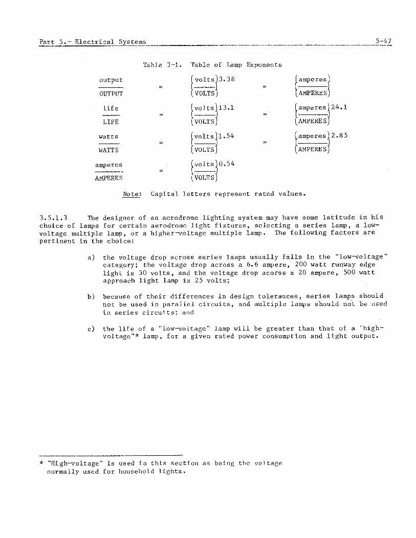
Table 3-1. Table of tamp Exponents
ou tpu t - - -
OUTPUT
l i f e amperes 24.1 - - - -
LIFE [ A.MPEmJ
w a t t s amperes 2.85 - - - WATT s [mpEm,i
amperes - - AMPERES
Note: C a p i t a l l e t t e r s r e p r e s e n t r a t e d va lues .
3.5.1.3 The d e s i g n e r of a n aerodrome l i g h t i n g sys tem may have some l a t i t u d e i n h i s cho ice of lamps f o r c e r t a i n aerodrome l i g h t f i x t u r e s , s e l e c t i n g a s e r i e s lamp, a low- v o l t a g e m u l t i p l e lamp, o r a h i g h e r - v o l t a g e m u l t i p l e lamp. The f o l l o w i n g f a c t o r s are p e r t i n e n t i n t h e choice:
a ) t h e v o l t a g e drop a c r o s s s e r i e s lamps u s u a l l y f a l l s i n t h e " low-vol tage" ca tegory ; t h e v o l t a g e drop a c r o s s a 6.6 ampere, 200 w a t t runway edge l i g h t i s 30 v o l t s , and t h e v o l t a g e drop a c o r s s a 20 ampere, 500 w a t t approach l i g h t lamp i s 25 v o l t s ;
b ) because of t h e i r d i f f e r e n c e s i n d e s i g n t o l e r a n c e s , s e r i e s lamps s h o u l d n o t be used i n p a r a l l e l c i r c u i t s , and m u l t i p l e lamps s h o u l d no'% be used I n series c i r c u i t s ; and
c ) t h e l i f e of a " low-vol tage" lamp w i l l be g r e a t e r t h a n t h a t of a "high- v o l t a g e w * lamp, f o r a g iven r a t e d power consumption and l i g h t ou tpu t .
-
* " H i g h v o l t a g e " i s used i n t h i s sectr ion as be ing t h e v o l t a g e normally used f o r household l i g h t s .

* z l 4 0
m. 5. E 3 ; , l20
2. F';,w * 3 Z a LY W u n 80
.(m
5
PER CENT NORMAL AMPERES
(a) SERIES TYPE LAMPS
PER CENT NORMAL VOLTS
(b) PARALLEL (MULTIPLE) TYPE LAMPS
Figure 3-8. E f f e c t s of c u r r e n t and v o l t a g e v a r i a t i o n s on o p e r a t i n g c h a r a c t e r i s t i c s of incandescen t lamps
3.5.1.4 Many lamps now be ing used f o r aerodrome l i g h t i n g a r e tungsten-halogen lamps. The f i l a m e n t s of t h e s e lamps a r e enc losed i n s m a l l q u a r t z tubes which c o n t a i n smal l amounts of a halogen, such a s i o d i n e , i n a d d i t i o n t o t h e u s u a l i n e r t f i l l gas . When t h e f i l a m e n t i s hea ted , t u n g s t e n evapora tes from t h e f i l a m e n t and condenses on t h e i n s i d e w a l l s of t h e lamp envelope. The vapour ized halogen combines w i t h t h i s condensed t u n g s t e n forming a vapour. This vapour t r a v e l s t o t h e h o t f i l a m e n t where i t d i s a s s o c i a t e s and r e d e p o s i t s t h e t u n g s t e n on t h e f i l a m e n t . This p r o c e s s reduces b lackening of t h e lamp bulb, i n c r e a s e s t h e l i f e of t h e lamp, m a i n t a i n s b e t t e r l i g h t i n t e n s i t y , and improves t h e e f f i c i e n c y of t h e lamp. The c o s t of t h e lamps i s however inc reased .
3.5.2.1 The lamps used i n t h e sequenc ge l i g h t s and n o t incandescen t lamps. The lamp i s a tube which may be formed i n t o v a r i o u s s h a p e s c o n t a i n - i n g an i n e r t g a s such a s argon o r k ryp ton which e m i t s l i g h t when an a r c i s c r e a t e d i n t h e gas . The power supply charges e l e c t r i c a l c a p a c i t o r s t o p rov ide power f o r t h e a r c and p rov ides a t r i g g e r i n g v o l t a g e t o i n i t i a t e t h e a r c upon a p p l i c a t i o n of t h e t r i g g e r i n g s i g n a l . The a r c i n t h e gas emi t s a h igh- in tensk ty f l a s h of i i g h t of s h o r t d u r a t i o n ( ~ c r o s e c o n d s ) which r a p i d l y expends t h e charge of t h e c a p a c i t o r s and e x t i n g u i s h e s t h e arc. Very h i g h voitages a r e P n v ~ i u e d f o r t he power s u p p l y and lamp. T h i s h a z a r d shou ld be cons lae red i n ~Zle des ign of tlae i i g i ~ t i r ~ g sysirem. The peak i i i te i l s iCy uf ; k s e l',gtits

may be very g r e a t bu t of s h o r t d u r a t i o n , The f l a s h must be i n t e g r a t e d t o determine t h e e f f e c t i v e i n t e n s i t y of t h e e m i t t e d l i g h t and i t s e f f e c t i v e n e s s a s a v i s u a l a i d . The f requency of f l a s h i n g of t h e s e l i g h t s i s l i m i t e d by t h e t ime r e q u i r e d t o r e c h a r g e t h e c a p a c i t o r s and u s u a l l y i s on ly a few t imes p e r second. The o u t p u t of t h e l i g h t i s pro- p o r t i o n a l t o t h e square of t h e v o l t a g e a p p l i e d t o t h e l i g h t f i t t i n g , u n l e s s i t has a r e g u l a t e d power supply .
3.5.2.2 . The h i g h e r e f f i c i e n c y of g a s e o u s d i s c h a r g e lamps encourages t h e i r use . Types of t h e s e lamps i n c l u d e f l u o r e s c e n t , mercury-vapour, meta l -hal ide , and low- o r h i g h - p r e s s u r e sodium-vapour l i g h t s . The u s e of l i g h t s of t h e s e t y p e s i s u s u a l l y l i m i t e d t o i l l u m i n a t i o n of a r e a s such a s apron a r e a s , excep t f o r t h e u s e of f l u o r e s c e n t lamps i n some taxiway edge l i g h t s and f o r i l l u m i n a t i n g s i g n s . When c o n s i d e r i n g u s i n g l i g h t s of t h e s e t y p e s t h e f o l l o w i n g a r e f a c t o r s t h a t should be i n v e s t i g a t e d .
a ) R e s t a r t i n e Some of t h e s e lamps cannot be r e s t a r t e d f o r s e v e r a l seconds t o minutes a f t e r t h e a r c i s ex t ingu i shed . Power i n t e r r u p t i o n s o r s w i t c h i n g can cause l o s s of l i g h t s a t c r i t i c a l t imes . Emergency l i g h t - i n g by o t h e r t y p e s of lamps may be d e s i r a b l e .
b ) Cold s t a r t i n g . Some of t h e s e lamps cannot be s t a r t e d o r are d i f f i c u l t t o s t a r t i n low ambient t empera tu res .
c ) I n t e n s i t y c o n t r o l . These lamps o f t e n a r e n o t capab le of i n t e n s i t y con- t r o l o r have a l i m i t e d range of c o n t r o l as compared t o incandescen t lamps.
d ) S t roboscop ic e f f e c t s . The s t r o b o s c o p i c e f f e c t s of t h e lamps may be d i s t u r b i n g . Where such l i g h t s a r e used, i n c l u d i n g f o r i l l u m i n a t i o n of a r e a s , t h e u s e of t h r e e - p h a s e e l e c t r i c a l supp ly sys tems w i t h a ba lance i n connec t ing t h e l i g h t s may be d e s i r a b l e .
e ) T y p i c a l l y t h e l i g h t e m i t t e d from t h e s e lamps covers a l i m i t e d p a r t of t h e v i s u a l spectrum. Th i s makes r e c o g n i t i o n of co lour coding d i f f i c u l t a s c o l o u r s may n o t have t h e i r o r d i n a r y appearance when i l l u m i n a t e d by gaseous-discharge lamps. The c o l o u r " red" i s par- t i c u l a r l y a f f e c t e d .
3.6 METHODS OF OBTAINING INTEGRITY AND RELIABILITY FOR AERODROME LIGHTING
3.6.1 D e f i n i t i o n s of terms
3.6.1.1 The terms i n t e g r i t y and r e l i a b i l i t y a s a p p l i e d t o aerodrome l i g h t i n g a r e n o t p r e c i s e , e a s i l y d e f i n e d o r measured terms. Previous e f f o r t s t o d e f i n e t h e s e terms have concluded t h a t r e l i a b i l i t y i s a q u e s t i o n of mean t ime between f a i l u r e of components w h i l e i n t e g r i t y i s a q u e s t i o n compris ing such m a t t e r s as f a i l u r e s u r v i v a l of t h e o v e r a l l system. It i s cons ide red t h a t v i s u a l a i d s shou ld have a comparable i n t e g r i t y and r e l i a - b i l i t y t o t h a t a f f o r d e d by non-visual a i d s . Thus r e l i a b i l i t y i s a f f e c t e d by t h e se lec - t i o n of components and o p e r a t i o n a l u s e , aiid i n t e g r l t j i i s a f f e c t e d by t h e d e s i g n and i n s t a l l a t i o n of t h e systems and maintenance of t h e equipment. It i s d i f f i c u l t t o s t a t e what t h e r e l i a b i l i t y of present v i s u a l a ids i s , In g e n e r a l i t i s c o n s i d e r e d chat w e l l
designed and mainta ined v i s u a l a i d s have a very h i g h i n t e g r i t y and t h a t t h e p r o b a b i l i t y of a f a i l u r e o c c u r r i n g a t a c r i t i c a l moment i s extremely low. Never the less a l l reason- a b l e e f f o r t s should be made t o improve upon i n t e g r i t y and r e l i a b i l i t y . E l e c t r i c a l f a c - t o r s which a f f e c t i n t e g r i t y and r e l i a b i l i t y may be c l a s s i f i e d as fo l lows :
a ) f a i l u r e of t h e c i r c u i t ;
b ) f a i l u r e of t h e power supp ly ; and
c ) f a i l u r e of t h e c o n t r o l c i r c u i t .
3.6.2.1 Reducing f a i l u r e of t h e c i r c u i t . A s t a n d a r d p r a c t i c e i s t o u s e s e v e r a l c i r c u i t s t o p reven t a f a i l u r e of one c i r c u i t b lack ing o u t a n e n t i r e l i g h t i n g system. Four c i r c u i t s a r e sometimes employed f o r l i g h t i n g t h e approach and t h r e s h o l d . One c i r c u i t i s used f o r t h e t h r e s h o l d l i g h t s and t h r e e f o r t h e approach l i g h t i n g system. The l a t t e r t h r e e c i r c u i t s a r e s o des igned t h a t i f one shou ld f a i l on ly e v e r y t h i r d b a r r e t t e would be o u t of opera t ion . Where a l i g h t i n g p a t t e r n i s f e d by s e v e r a l c i r c u i t s , t h e p r a c t i c e of each c i r c u i t f e e d i n g one p a r t i c u l a r g e o g r a p h i c a l s e c t i o n of t h e p a t t e r n i s n o t recommended because l o s s of one c i r c u i t can t h e n change t h e p a t t e r n i n t o something e n t i r e l y d i f f e r e n t . For example, a n approach l i g h t i n g p a t t e r n compris ing a c e n t r e l i n e and f i v e c r o s s b a r s i f f e d i n two d i s t i n c t h a l v e s by two c i r c u i t s cou ld change from a c e n t r e l i n e and f i v e b a r sys tem t o a c e n t r e l i n e and t h r e e b a r sys tem w i t h t h e l o s s of one c i r c u i t .
3.6.2.2 Reducing f a i l u r e of t h e power supply . Steps can be t aken t o e n s u r e a con- t i n u o u s supply of power t o t h e l i g h t i n g system. h e of t h e most s imple and most r e l i a - b l e i s t o have a l t e r n a t i v e s o u r c e s of power from two d i f f e r e n t g e n e r a t o r s which a r e capab le of a u t o m a t i c a l l y s t a r t i n g i n c a s e of a power f a i l u r e . Equipment h a s been devel- oped which w i l l reduce t o a very s h o r t i n t e r v a l t h e t ime between power f a i l u r e and d e l i - *- --" V C L ~ ~f c u r r e n t from t h e a l t e r n a t i v e system. Switching r a t e s a s l o w a s 0 = 3 t o 0.5 seconds a r e be ing ob ta ined f o r equipment i n s t a l l e d i n c o n j u n c t i o n w i t h p r e c i s i o n approach runways. Switching r a t e s f o r o t h e r systems vary between 10 t o 20 seconds . Another procedure which i s used i s t o o p e r a t e from t h e secondary g e n e r a t o r s c o n t i n u o u s l y dur ing c r i t i c a l t imes such a s d u r i n g low v i s i b i l i t y c o n d i t i o n s o r when a s t o r m i s f o r e c a s t . I n case of a f a i l u r e of t h e g e n e r a t o r , t h e swi tch-over i s t h e n made t o t h e primary power supply . These systems and arrangements a r e d i s c u s s e d i n Chap te r 2.
3.6.2.3 Sometimes a l t e r n a t e c o n t r o l c i r - c u i t s a r e neg lec ted . C a r e f u l a t t e n t i o n i s given t o t h e l i g h t i n g c i r c u i t s and secondary power s u p p l i e s a r e provided f o r them, b u t p r o v i s i o n of a l t e r n a t e c i r c u i t s f o r c o n t r o l s of t h e l i g h t s from t h e c o n t r o l tower i s overlooked. The p r o b a b i l i t y of a c o n t r o l c i r - c u i t f a i l i n g may be e q u a l t o t h a t of a l i g h t i n g c i r c u i t f a i l i n g , and d u a l c o n t r o l c i r c u i t s shou ld be provided.
3.6.2.4 Designing f o r i n t e g r i t y and r e l i a b i l i t y . The d e s i g n and i n s t a l l a t i o n of aerodrome l i g h t i n g systems can a f f e c t i n t e g r i t y and r e l i a b i l i t y i n ways o t h e r t h a n s e l e c t i o n of components and i n t e r l e a v i n g of c i r c u i t s . These f e a t u r e s a r e o f t e n t h e same a s t h o s e used t o reduce and s i m p l i f y maintenance. Some of t h e f e a t u r e s de te rmined i n t h e d e s i g n d e c i s i o n s a r e i n s t a l l i n g c a b l e s i n condu i t ( d u c t s ) i n s t e a d of d i r e c t b u r i a l , u s i n g i n s e t l i g h t s i n s t e a d oE e l e v a t e d l i g h t s i n a r e a s where s u r f a c e t r a f f i c o f t e n col - l i d e s w i t h t h e l i g h t f i x t u r e s , p rov id ing ground-wire c i r c u i t s throughout t h e sys tem ts reduce t h e e f f e c t s of iigh~ning and h i g h v o l t a g e s u r g e s , equ ipp ing l i g h t f i x t u r e s wkth

h e a t i n g e lements t o e l i m i n a t e m o i s t u r e condensat ion and i c i n g problems, e t c . Rel ia- b i l i t y and i n t e g r i t y a r e f a c t o r s which should be considered i n t h e d e s i g n and i n s t a l l a t i o n .
3.7 MONITORING OF AERODROME LIGHTING CIRCUITS
3.7.1 Methods of moni to r ing
3.7.1.1 8.3 of Annex 14 s t a t e s t h a t a system of moni tor ing v i s u a l a i d s should be employed t o ensure l i g h t i n g system r e l i a b i l i t y . Monitoring may be accomplished by v i s u a l o b s e r v a t i o n s o r by an au tomat ic s e n s o r . Visual moni to r ing , excep t f o r what A i r T r a f f i c C o n t r o l s e e s and p i l o t s r e p o r t , is seldom used. Some of t h e moni tor ing of l i g h t i n g systems i n u s e c o n s i s t of i n d i c a t o r l i g h t s which i n d i c a t e o n l y t h a t t h e swi tches which c o n t r o l t h e c i r c u i t s a r e turned t o ON o r t h a t one o r more l i g h t s i n a c i r c u i t have f a i l e d . R e l i a b l e moni to r ing is very d e s i r a b l e , but p a r t i a l o r incomplete moni tor ing can c r e a t e a s e c u r e f e e l i n g which h inders i n s t e a d of a i d s i n r e l i a b i l i t y . Examples a r e : i n d i c a t o r l i g h t s which respond only t o s w i t c h p o s i t i o n o r c o n t r o l r e l a y o p e r a t i o n may not d e t e c t a ma l func t ion ing cons tan t -cur ren t r e g u l a t o r o r a grounded ou t l i g h t i n g c i r c u i t ; o r moni tors of power waveform d i s t o r t i o n t o d e t e c t lamp f a i l u r e s may not respond t o f a u l t s of t h e l i g h t i n g c i r c u i t s o r f a i l u r e of power o r c o n t r o l equipment.
3.7.2 Desien of moni tor ing d e v i c e s
3.7.2.1 The i d e a l moni tor ing dev ice f o r aerodrome l i g h t s measures t h e i n t e n s i t y of each l i g h t i n t h e d i r e c t i o n s from which i t w i l l be observed and i n d i c a t e s any d e f i c i e n - c i e s by l o c a t i o n and amount. Such moni tor ing may not be p r a c t i c a l o r p o s s i b l e . The d e s i g n of moni tor ing dev ices should cons ide r r e l a t e d in fo rmat ion t h a t would be h e l p f u l a s w e l l a s t h e f a i l u r e s which they can d e t e c t . Some d e v i c e s may s e n s e important in fo rmat ion which is not p resen ted by t h e i n d i c a t o r . I n s t r u c t i o n s f o r u s e of the moni tor ing system should e x p l a i n t h e l i m i t a t i o n s as w e l l a s t h e c a p a b i l i t i e s of t h e system. The q u a n t i t i e s u s u a l l y measured a r e c u r r e n t , v o l t a g e , power, waveform, t ime, and p h o t o e l e c t r i c emiss ion. Recorders of t h e s e values a r e a form of moni tor , but t h i s type in fo rmat ion is seldom used f o r immediate response o r t o produce a c t i o n s a u t o m a t i c a l l y .
3.7.3 Classes of moni to r s
3.7.3.1 Monitors may be c l a s s e d a s a c t i v e o r pass ive . Act ive moni tors t a k e a predetermined a c t i o n when a s p e c i f i c c o n d i t i o n is sensed o r a t a s e l e c t e d t ime a f t e r t h e c o n d i t i o n occurs . Examples of moni tors i n t h i s c l a s s a r e t h e primary source v o l t a g e s e n s o r s which a u t o m a t i c a l l y s t a r t t h e secondary engine-generator s e t and t r a n s f e r t h e l o a d when t h e primary power source f a i l s , o r t h e high i n t e n s i t y t ime l i m i t c o n t r o l which a u t o m a t i c a l l y r e s e t s t o a lower i n t e n s i t y s t e p and sounds a buzzer and/or e n e r g i z e s an i n d i c a t o r lamp a f t e r t h e l i g h t s have been a t f u l l i n t e n s i t y f o r 15 minutes.* Pass ive moni tors p rov ide a s i g n a l such a s an i n d i c a t o r lamp o r buzzer when a predetermined
* A u t o m t $ c r e s e t t i n g of t h e i n t e n s i t y Is n o t d e s i r a b l e s i r lce t h e change e ~ u l c " ; be made -L .," a pi:ot is i:- a c-'"' --' - -
l I L LLiCai p . . l ?' .-.C I l n --F;
a L L W L LILO aypLua%-I-Il.
c o n d i t i o n occurs and does not change any of t h e systems o p e r a t i o n s . A human o p e r a t o r must e v a l u a t e t h e meaning of t h e s i g n a l and t a k e t h e a p p r o p r i a t e a c t i o n . Examples of p a s s i v e moni tor ing a r e t h e sequence-f lashing l i g h t s monitor which a l e r t s when a p r e s e l e c t e d number of l i g h t s is i n o p e r a t i v e , o r t h e i n d i c a t o r lamp which shows t h a t s p e c i f i c c i r c u i t s a r e energized and opera t ing .
3.7.4 Monitor o v e r r i d e c o n t r o l s
3.7.4.1 Often c o n t r o l s o r procedures which can be used t o o v e r r i d e o r circumvent t h e a c t i o n of t h e monitor a r e provided. By a c t i v a t i n g a s p e c i a l c i r c u i t o r r e s e t t i n g a c o n t r o l , t h e o p e r a t o r can main ta in t h e systems o p e r a t i o n wi thou t change f o r new o r i n d e f i n i t e t i m e per iod. The s i g n a l i n d i c a t i n g t h e moni to r ' s r esponse may be provided dur ing t h e o v e r r i d e o p e r a t i o n t o keep t h e o p e r a t o r informed t h a t t h e sys tem i s i n an u n d e s i r a b l e o p e r a t i n g s t a t u s . An example i s t o r e s e t t h e t imer t o f u l l i n t e n s i t y o p e r a t i o n s a t t h e beginning of each approach i n low v i s i b i l i t y c o n d i t i o n s t o ensure t h a t t h e l i g h t s w i l l n o t a u t o m a t i c a l l y be changed t o a lower i n t e n s i t y d u r i n g t h e approach.
3.8 ELECTRICAL CIRCUITS FOR RADIO NAVIGATION AIDS
3.8.1 Types of r a d i o n a v i g a t i o n a i d s
3.8.1.1 The types of r a d i o n a v i g a t i o n a i d s which may be l o c a t e d on o r n e a r t h e aerodrome and r e q u i r e e l e c t r i c a l power e i t h e r from t h e aerodrome power sys tem o r a s a s e p a r a t e system v a r i e s wi th t h e aerodrome. These r a d i o n a v i g a t i o n a l a i d s o f t e n i n c l u d e ins t rument l and ing s y s t e m (ILS), ve ry h igh f requency o m n i d i r e c t i o n a l r a d i o range (VOR), non-d i rec t iona l beacon ( N D B ) , d i r e c t i o n f i n d i n g (DF) f a c i l i t i e s , p r e c i s i o n approach r a d a r sys tems, d i s t a n c e measuring equipment (DME), a i r s u r v e i l l a r ~ c e r a d a r (ASR), and s i m i l a r equipment, Most aerodromes a r e equipped w i t h some of t h e s e dev ices and t h e e l e c t r i c a l power requirements may r e q u i r e s p e c i a l c o n s i d e r a t i o n . Note t h a t t h e ILS f o r ca tegory I1 and 111 o p e r a t i o n s i s more p r e c i s i o n equipment t h a n t h a t r e q u i r e d f o r ca tegory I o p e r a t i o n s .
3.8.2 E l e c t r i c a l c h a r a c t e r i s t i c s
3.8.2.1 E l e c t r i c a l power f o r r a d i o n a v i g a t i o n a i d s i s u s u a l l y a l t e r n a t i n g c u r r e n t ( a c ) . B a t t e r i e s may be used t o provide power f o r s t a r t i n g secondary power s o u r c e s and t o supply energy f o r some u n i n t e r r u p t i b l e power systems. This a c power i s u s u a l l y e i t h e r 50 o r 60 h e r t z .
3.8.2.2 Primary power. For r a d i o n a v i g a t i o n a i d s l o c a t e d on o r a d j a c e n t t o t h e aerodrome, t h e primary power source i s u s u a l l y t h e same a s t h e aerodrome pr imary source . 'I'hese sources a r e d i scussed i n paragraph 2.1.2, Since t h e t o t a l k i l o w a t t s r e q u i r e d by r a d i o n a v i g a t i o n a i d s u s u a l l y is n o t l a r g e , t h e i n p u t power t o t h e s e i n s t a l l a t i o n s i s o f t e n t r a n s m i t t e d a t t h e i n t e r m e d i a t e v o l t a g e l e v e l and f e d t o Local d i s t r i b u t i o n t rans formers f o r step-down t o t h e v o l t a g e s u i t a b l e f o r t h e equipment,
3.8.2.3 Secondary power* Since t h e s e r a d i o n a v i g a t i o n a i d s provide s i g n a l s f o r ins t rument guidance of t h e a i r c r a f t and a r e e s s e n t i a l f o r o p e r a t i o n s i n a t l e a s t some c o n d i t i o n s , Annex 10, Voiurne I, Par t i , C'napter 2 r e q u i r e s secondary power aoinrces f o r most of t h e s e r a d i o a i d s . The switch-over time f o r some of t h e s e r a d i o n a v i g a t i o n a i d s a r e shown i n Table 2-1 and d iscussed i n paragraphs 2 , 2 and 2 , 3 o f t h i s manual. The rad io navis--: ,aLLuu -- a i d s a r e o f t e n loca ted In - . isolated areas o r areas w e l l s e p a r a t e d from

o t h e r b u i l d i n g s r e q u i r i n g e l e c t r i c a l power. Secondary power i s u s u a l l y p rov ided by engine-generator power u n i t s because, f o r t h e amount of power needed, secondary power may be more economical t o i n s t a l l than a second f e e d e r t o t h e s i t e . I f a n independent power s o u r c e i s used, t h e f e e d e r from t h i s s o u r c e should be i n a s e p a r a t e d u c t o r even a s e p a r a t e r o u t e from t h e pr imary power f e e d e r . Some of t h e r a d i o n a v i g a t i o n a i d s a r e more l i k e l y t o r e q u i r e u n i n t e r r u p t i b l e power s u p p l i e s than a r e aerodrome l i g h t i n g sys tems. The redundant c o n f i g u r a t i o n of F igure 2-3 i s o f t e n a d v i s a b l e f o r some r a d i o n a v i g a t i o n a i d s and r e l a t e d computers.
3.8.2.4 Groundin@ S t a b l e grounding t h a n paragraph 2.5.14, a p p l
Radio n a v i g a t i o n a i d s may r e q u i r e lower r e s i s t a n c e and more do aerodrome l i g h t i n g systems. The grounding, as d i s c u s s e d i n i e s b u t grounding networks a r e more o f t e n r e q u i r e d . The grounding
requ i rements of bo th t h e e l e c t r i c a l sys tem a t t h e r a d i o a i d s b u i l d i n g and a t t h e an tenna shou ld be cons ide red c a r e f u l l y . Some of t h e an tennas may r e q u i r e s p e c i a l grounding p l a n e s i n some l o c a t i o n s . P r o t e c t i o n of t h e grounding systems from c o r r o s i o n may be n e c e s s a r y f o r some r a d i o n a v i g a t i o n a i d s .
3.8.2.5 Ligh tn ing a r r e s t e r s . Lightning and s u r g e p r o t e c t i o n f o r r a d i o n a v i g a t i o n a i d s i s more impor tan t t h a n f o r most e l e c t r i c a l systems because t h e r a d i o s i g n a l s a r e more e a s i l y a f f e c t e d , and an tennas a r e o f t e n t h e t a r g e t of l i g h t n i n g s t r i k e s . Paragraph 2.5.12 d i s c u s s e s l i g h t n i n g p r o t e c t i o n . Also t h e s e r a d i o a i d s o f t e n u s e s o l i d - s t a t e d e v i c e s which a r e v u l n e r a b l e t o v o l t a g e and power s u r g e s . Often b a t t e r i e s o r c o n v e r t e r s a r e used t o p rov ide d c power f o r t h e s o l i d - s t a t e dev ices t o e l i m i n a t e o r r educe t h e l i g h t n i n g and power s u r g e problems.
3.8.2.6 Feeds t o an tenna a r r a y s . The c a b l i n g between t h e r a d i o equipment and t h e an tenna o f t e n r e q u i r e s s p e c i a l handl ing. Usually c o a x i a l c a b l e s a r e used t o conduct t h e s e s i g n a l s . The c a b l e may be r e q u i r e d t o p rov ide a p roper impedance match between t h e o u t p u t of t h e s i g n a l g e n e r a t o r and t h e i n p u t t o t h e antenna bu t may a l s o need t o be of a n a c c u r a t e l e n g t h f o r f requency phasing. The r a d i o equipment o f t e n e x p l i c i t l y s t a t e s t h e s e c a b l i n g requ i rements b u t some r a d i o a i d s may n o t f u r n i s h t h e s e d e t a i l s . The f e e d s t o t h e antenna a r r a y s should be c a r e f u l l y coord ina ted w i t h t h e s u p p l i e r of t h e equipment and t h e i n s t a l l e r s of t h e an tenna and r a d i o equipment.
3.8.3,1 Uses of c o n t r o l c i r c u i t s . The c o n t r o l c i r c u i t s f o r r a d i o n a v i g a t i o n a i d s a r e p r i m a r i l y used t o e n e r g i z e and deenerg ize t h e sys tems, t o t r a n s f e r f rom primary t o stand-by o r a l t e r n a t e t r a n s m i t t e r , and t o t r a n s f e r from primary t o secondary power s o u r c e . 3.8.3.2 The r a d i o n a v i g a t i o n a i d s may be l o c a t e d on t h e aerodrome o r s e v e r a l mi les away. Most r a d i o n a v i g a t i o n a i d s p rov ide l o c a l c o n t r o l a t t h e t r a n s m i t t e r s i t e and remote c o n t r o l a t one o r more a i r t r a f f i c o r equipment c o n t r o l s i tes. I f t h e r a d i o a i d s a r e l o c a t e d on o r nea r t h e aerodrome and t h e c o n t r o l s a r e r e l a t i v e l y s i m p l e , a c o r d c power c o n t r o l c i r c u i t s s i m i l a r t o t h o s e used f o r aerodrome l i g h t i n g may be used. These c o n t r o l c i r c u i t s a r e d i s c u s s e d i n paragraphs 3.4.1.4, 3.4.2.3, 3.4.3.1, and 3.4.3.2 a s gu ides . If t h e d i s t a n c e s a r e g r e a t o r t h e c o n t r o l c i r c u i t s a r e complex, t e l ephone c i r c u i t s a r e o f t e n used f o r remote c o n t r o l . By d i a l i n g a p a r t i c u l a r code of one, two, o r t h r e e numbers, t h e d e s i r e d s w i t c h i n g can be ob ta ined . The t e l ephone d i a l i n g c o n t r c l sys tem i s a form of m u l t i p l e x c o n t r o l which can be expanded f o r c o n t r o i l i n g ve ry complex systems.

3.8.4 R e l i a b i l i t y and i n t e g r i t y of r a d i o n a v i g a t i o n a i d s
8.4.1 A s d i s c u s s e d i n paragraph 3.6.1, t h e r e l i a b i l i t y and i n t e g r i t y of non-visual d s ( r a d i o n a v i g a t i o n a i d s ) should be comparable t o t h a t of v i s u a l a i d s . I n a d d i t i o n
t h e e l e c t r i c a l f a c t o r s a f f e c t i n g aerodrome l i g h t i n g of f a i l u r e of t h e c i r c u i t , f a i l u r e of t h e power supply , and f a i l u r e of t h e c o n t r o l c i r c u i t , t h e r a d i o n a v i g a t i o n a i d s must t r a n s m i t a s i g n a l having s e v e r a l q u a l i t i e s w i t h i n a c c e p t a b l e t o l e r a n c e s . These s i g n a l q u a l i t i e s and t o l e r a n c e s f o r t h e s e a i d s a r e d i s c u s s e d i n Annex 10 , Volume I , P a r t 1 , Chapter 3. Not only must t h e equipment be o p e r a t i n g and t r a n s m i t t i n g a s i g n a l , bu t i t should be monitored t o a s s u r e an accep tab le s i g n a l . Usual ly no s i g n a l is p r e f e r a b l e t o a bad s i g n a l . To improve r e l i a b i l i t y many r a d i o n a v i g a t i o n a i d s have a l t e r n a t e t r a n s m i t t e r s ene rg ized and ready f o r swi tch ing t o t r a n s m i s s i o n upon f a i l u r e of t h e pr imary t r a n s m i t t e r o r of a d e f i c i e n t s i g x a l . The r a d i o n a v i g a t i o n a i d s o f t e n have i n d i v i d u a l secondary power sources t o a u t o m a t i c a l l y assume power i f t h e primary power s o u r c e f a i l s . The c o n t r o l system should be designed s o t h a t i f t h e c o n t r o l should f a i l when t h e a i d is being opera ted by remote manual c o n t r o l , t h e r a d i o a i d w i l l remain o p e r a t i n g and swi tch t o au tomat ic c o n t r o l . Attachment F t o P a r t I of Annex 10 c o n t a i n s a d d i t i o n a l guidance m a t e r i a l r e g a r d i n g r e l i a b i l i t y and a v a i l a b i l i t y of r a d i o n a v i g a t i o n a i d s .
Monitoring of r a d i o n a v i g a t i o n a i d s
3.8.5.1 S igna l moni tor ing. The moni tor ing of r a d i o n a v i g a t i o n a i d s , excep t f o r l i g h t s t o i n d i c a t e t h a t the equipment is energ ized , r e q u i r e s au tomat ic s e n s o r s of the s i g n a l t o determine i f i t i s a c c e p t a b l e . S e v e r a l q u a l i t i e s of t h e s i g n a l and func t ion- ing of s e c t i o n s of t h e equipment may r e q u i r e monitoring. The moni tor ing of t h e s i g n a l q u a l i t y f o r t h e s e r a d i o a i d s a r e d i s c u s s e d i n Annex 10, Volume I, P a r t 1, Chap te r 3 . The monitor may be requ i red t o a u t o m a t i c a l l y swi tch t o the a l t e r n a t e t r a n s m i t t e r o r d e a c t i v a t e t h e equipment and a l s o s i g n a l t h e des igna ted c o n t r o l p o i n t s of t r a n s m i t t e d s i g n a l d e f i c i e n c i e s . Other l e s s e s s e n t i a l r a d i o n a v i g a t i o n a i d s may have moni tors which i n d i c a t e a t t h e c o n t r o l p o i n t s i f o p e r a t i o n is s a t i s f a c t o r y , I f i t is no t s a t i s f a c t o r y , +-L.- e l l= o p e r a t o r can make the r e q u i r e d t r a n s f e r s , For t h e r a d i o a i d s wi th c r i t i c a l s i g n a l
r equ i rements , t h e monitor may a u t o m a t i c a l l y d e a c t i v a t e t h e equipment t o p reven t t r a n s - miss ion of a d e f i c i e n t s i g n a l i f a s a t i s f a c t o r y s i g n a l from an a l t e r n a t e t r a n s m i t t e r is n o t ob ta ined .
3.8.5.2 Monitoring a u x i l i a r y f u n c t i o n s . Severa l o t h e r f u n c t i o n s may be monitored t o a s s u r e s a t i s f a c t o r y o p e r a t i o n of r a d i o n a v i g a t i o n a i d s . These may i n c l u d e b a t t e r y v o l t a g e s f o r t h e s t a r t i n g of t h e secondary power s e t o r f o r o p e r a t i n g u n i n t e r r u p t i b l e power s u p p l i e s , ambient or room temperature t o mainta in s u i t a b l e environments f o r the equipment, and f u e l supply f o r t h e secondary power source . These moni tors may provide alarms o r i n d i c a t i o n s t h a t the f u n c t i o n s exceed e s t a b l i s h e d c r i t e r i a .
3.9 ACCEPTANCE TESTING OF AERODROME ELECTRICAL CIRCUITS
3.3.1.2 The t e s t procedures d e s c r i b e d i n t h i s s e c t i o n app ly t o t h e accep tance t e s t s of new i n s t a l l a t i o n s and should be performed be fore making t h e sys tem o p e r a t i o n a l .
3.9.2.1 Each i n s t a l l a t i o n c o n t r a c t should i n c l u d e a guaran tee c l a u s e s p e c i f y i n g a p e r i o d of a t l e a s t one y e a r d u r i n g which t h e i n s t a l l i n g c o n t r a c t o r can be h e l d respons i - b l e f o r r e p a i r i n g and r e p l a c i n g a l l c a b l e and equipment f a i l u r e s r e s u l t i n g from poor work o r d e f e c t i v e m a t e r i a l s and equipment. (Damp o r d i r t y c a b l e connec to r s and c a b l e damage due t o f a u l t y i n s t a l l a t i o n p r a c t i c e s o f t e n f a i l s e v e r a l months a f t e r i n s t a l l a t i o n . )
3.9.3.1 Visua l examination. The most impor tan t of a l l i n s p e c t i o n and t es t procedures a r e thorough v i s u a l i n s p e c t i o n s . Visua l i n s p e c t i o n s should be made f r e q u e n t l y dur ing i n s t a l l a t i o n , a t completion of i n s t a l l a t i o n , and b e f o r e e n e r g i z i n g t h e c i r c u i t s . A c a r e f u l v i s u a l i n s p e c t i o n w i l l r e v e a l d e f e c t s t h a t can be c o r r e c t e d p r i o r t o accep tance t e s t s and e n e r g i z a t i o n . Ser ious damage may occur i f d e f e c t s a r e s u b j e c t e d t o e l e c t r i c a l t e s t s o r e n e r g i z a t i o n . Visua l i n s p e c t i o n s should i n c l u d e i n s p e c t i o n a p p r a i s a l o f :
a ) c o r r e c t n e s s of e x t e r n a l connec t ions ;
b ) good work performance;
c ) c l e a n l i n e s S;
d ) s a f e t y haza rds ; and
e ) s p e c i f i c requirements f o r i n d i v i d u a l i t e m s .
A l l equipment manufactured under s p e c i f i c a t i o n s shou ld pass s t r i c t f a c t o r y t e s t s p r i o r t o shipment, bu t i t should be v i s u a l l y i n s p e c t e d f o r s h i p p i n g damage immediate ly upon r e c e i p t .
3.9.3.2 . The pr imary and secondary c a b l e l e a d s of t h e t r ans fo rmers should be s u p p l i e d w i t h f a c t o r y i n s t a l l e d molded connec to r s . Visual i n s p e c t i o n of t h e s e i t ems d u r i n g i n s t a l l a t i o n i s e s p e c i a l l y i m p o r t a n t , a s minor c u t s , b r u i s e s , o r mishandl ing may r e s u l t i n a p r o g r e s s i v e d e t e r i o r a t i o n which w i l l e v e n t u a l l y cause complete f a i l u r e , bu t n o t u n t i l some t ime a f t e r accep tance t e s t s . During i n s t a l l a t i o n , t h e s e i tems shou ld be i n s p e c t e d t o determine t h e fo l lowing :
a ) t h a t t h e mating s u r f a c e s of molded connec to r s a r e c l e a n and d r y when plugged toge the r . I f c l e a n and d ry i n s i d e , t h e s e h i g h v o l t a g e connectors w i t h t a p i n g form a connec t ion e q u a l t o , o r s u p e r i o r t o , a conven t iona l h igh v o l t a g e s p l i c e . Conversely, i f t h e y a r e wet o r d i r t y i n s i d e , no amount of t a p i n g can produce a s a t i s f a c t o r y connec t ion . Two o r t h r e e t u r n s of t a p e a r e recommended t o ho ld t h e connec to r t o g e t h e r and keep t h e p a r t i n g l i n e s c l e a n . C l e a n l i n e s s of mating s u r f a c e s can b e s t be i n s u r e d by keeping t h e f a c t o r y i n s t a l l e d caps i n p l a c e u n t i l t h e f i n a l connect ion i s made. The mating s u r f a c e s of uncapped connec to r s should not be l a i d down, touched, o r b rea thed upon. I f i t i s necessa ry t o break a connect ion, t h e connec to r s should be immediately capped;

5-5 6 Aerodrome Desirrn Manual
b ) t h a t t h e connec to r s a r e complete ly plugged t o g e t h e r . A f t e r i n i t i a l p lugging, t r apped a i r p r e s s u r e may p a r t i a l l y d isengage t h e p l u g and r e c e p t a c l e . I f t h i s happens, w a i t a few seconds and push them t o g e t h e r aga in . Apply two o r t h r e e t u r n s of t a p e t o hold them i n p l a c e ;
c ) t h a t t h e c a b l e s have n o t been c u t by s h o v e l s , k inked, crushed by v e h i c l e wheels , b r u i s e d by r o c k s , o r damaged i n any way d u r i n g hand l ing and i n s t a l l a t i o n ;
d ) t h a t t h e c a b l e s a r e b u r i e d t o t h e s p e c i f i e d d e p t h below f i n i s h e d g r a d e and a l l o t h e r d e t a i l e d requirements of t h e i n s t a l l a t i o n s p e c i f i c a t i o n a r e accomplished;
e ) t h a t t h e c a b l e s do n o t d i r e c t l y c r o s s each o t h e r and a r e s e p a r a t e d by t h e r e q u i r e d d i s t a n c e s ;
f ) t h a t sc reened m a t e r i a l has been p laced under and over t h e c a b l e s , and t h a t rocks o r pebbles do n o t c o n t a c t t h e c a b l e s ; and
g ) t h a t t h e c a b l e s have n o t been b e n t s h a r p l y where they e n t e r ( o r l e a v e ) a condu i t and a r e suppor ted p roper ly by tamped ground, s o f u t u r e s e t t l i n g cannot cause s h a r p bends.
3.9.3.3 Constant-current r e g u l a t o r i n s p e c t i o n . Each cons tan t -cur ren t r e g u l a t o r should be i n s p e c t e d t o e n s u r e t h a t p o r c e l a i n bushings have n o t been cracked, no sh ipp ing damage h a s o c c u r r e d , connec t ions a r e c o r r e c t , swi tches and r e l a y s o p e r a t e f r e e l y and a r e n o t t i e d o r blocked, f u s e s ( i f r e q u i r e d ) a r e c o r r e c t , and t h a t t h e o i l l e v e l o f o i l - f i l l e d r e g u l a t o r s i s c o r r e c t . Only r e l a y p a n e l covers shou ld be removed f o r t h i s i n s p e c t i o n . It i s n o t necessa ry t o open t h e main t ank of o i l - f i l l e d r e g u l a t o r s . Infomrat ion on t h e r e g u l a t o r i n s p e c t i o n p l a t e must be fo l lowed. All covers shou ld be c leaned and t i g h t l y r e p l a c e d a f t e r i n s p e c t i o n and t e s t s a r e completed.
3.9.3.4 An i n s p e c t i o n should be made t o determine t h a t t h e co lour , q u a n t i t y , and l o c a t i o n s of l i g h t s a r e i n accordance w i t h t h e i n s t a l l a t i o n drawings. Each l i g h t should be i n s p e c t e d t o determine t h a t i t i s o p e r a b l e , t h a t g l a s s i s n o t broken o r cracked, t h a t c o r r e c t iamps a r e i n s t a l l e d , and that -it has been p r o p e r l y l e v e l e d and aimed.
3.9.3.5 I n s p e c t i o n of misce l l aneous components. Components such a s c o n t r o l p a n e l s , r e l a y c a b i n e t s , pane lboards , e t c . , should be v i s u a l l y i n s p e c t e d f o r damage, c o r r e c t connec t ions , p roper f u s e and c i r c u i t - b r e a k d e r r a t i n g s , and compliance w i t h t h e i n s t a l l a t i o n drawings.
3.9.3.6 System o p e r a t i o n t e s t . A f t e r components and c i r c u i t s have been i n s p e c t e d , a s i n d i c a t e d i n t h e p receed ing pa ragraphs , t h e e n t i r e sys tem should be r e s t e d a s fo l lows :
a ) each s w i t c h of t h e l i g h t i n g p a n e l s i n t h e c o n t r o l tower shou ld be o p e r a t e d s o t h a t e a c h s w i t c h p o s i t i o n i s reached a t l e a s t t w i c e , During t h i s p r o c e s s , a l l L igh t s and v a u l t equipment should be observed t o determine t h a t each s w i t c h p roper ly c o n t r o l s t h e cor respond ing c i r c u i t ;
P a r t 5. - E l e c t r i c a l Svstems 5-57
b ) t h e above t e s t shou ld be r e p e a t e d u s i n g t h e p a n e l s i n t h e a l t e r n a t e c o n t r o l s t a t i o n ( v a u l t ) and t h e n r e p e a t e d a g a i n u s i n g t h e l o c a l c o n t r o l s w i t c h e s on t h e r e g u l a t o r s ; and
c ) e a c h l i g h t i n g c i r c u i t s h o u l d be t e s t e d by o p e r a t i n g i t c o n t i n u o u s l y a t maximurn i n t e n s i t y f o r a t l e a s t 6 hour s . V i s u a l i n s p e c t i o n s h o u l d be made a t t h e b e g i n n i n g and a t t h e end of t h i s t e s t t o d e t e r m i n e t h a t t h e c o r r e c t number of l i g h t s are o p e r a t i n g a t f u l l i n t e n s i t y . Dimming of some o r a l l o f t h e l i g h t s i n a c i r c u i t i s a n i n d i c a t i o n o f ground f a u l t s . In a d d i t i o n , t h e lamp- terminal v o l t a g e s h o u l d be measured on a t l e a s t one l i g h t t n e a c h m u l t i p l e c i r c u i t , t o d e t e r m i n e t h a t i t i s w i t h i n t 5 p e r c e n t of t h e r a t e d lamp v o l t a g e a s marked on t h e lamp.
3.9.4 E l e c t r i c a l tests of s e r i e s - c i r c u i t equipment
3.9.4.1 E l e c t r i c a l tests a r e h e l p f u l i n d e t e r m i n i n g t h a t t h e q u a l i t y o f t h e i n s t a l - l a t i o n i s a c c e p t a b l e and t h a t t h e per formance w i l l meet t h e o p e r a t i o n a l r e q u i r e m e n t s . Some o f t h e tests i n v o l v e t h e u s e and measurements of h i g h v o l t a g e c i r c u i t s . These t e s t s s h o u l d be performed o n l y by q u a l i f i e d p e r s o n s who a r e f a m i l i a r w i t h h i g h - v o l t a g e e l e c t r i c a l equipment and t h e s a f e t y p r e c a u t i o n s which must be obse rved .
3.9.4.2 E l e c t r i c a l tests on c a b l e . Cables b u r i e d i n e a r t h ( t h a t i s , n o t i n d u c t ) s h o u l d be t e s t e d b e f o r e and a f t e r b a c k f i l l i n g t h e c a b l e t r e n c h .
3.9.4.3 Each s e r i e s c i r c u i t s h o u l d be t e s t e d f o r c o n t i n u i t y by ohmmeter o r e q u i - v a l e n t method. The r e s i s t a n c e o f t h e c i r c u i t t o ground s h o u l d t h e n be checked w i t h a s u i t a b l e t e s t set t o make s u r e i t i s f r e e of grounds . Any f a u l t s i n d i c a t e d by t h e s e t e s t s s h o u l d be l o c a t e d and r e p a i r e d b e f o r e p roceed ing w i t h h igh -vo l t age t e s t s .
3.9.4.4 Each s e r i e s c i r c u i t s h o u l d be s u b j e c t e d t o h i g h v o l t a g e i n s u l a t i o n r e s i s t - ance t e s t s t o de t e rmine comple t f reedom f rom grounds . Whenever p o s s i b l e , t h e s e t e s t s shou ld be performed when t h e ground i s tho rough ly wet . Expe r i ence h a s shown t h a t c i r - c u i t s which p a s s i n s u l a t i o n r e s i s t a n c e t e s t s d u r i n g d r y wea the r may f a i l a f t e r a heavy r a i n . Each c i r c u i t , i n c l u d i n g t r a n s f o r m e r s , s h o u l d be t e s t e d a s f o l l o w s :
a ) Msconi lec t b o t h l e a d s f rom t h e r e g u l a t o r o u t p u t t e r m i n a l s . Suppor t b o t h l e a d s s o t h a t a i r gaps o f s e v e r a l i n c h e s e x i s t between b a r e c o n d u c t o r s and ground. Make s u r e t h a t t h e c a b l e s h e a t h i s c l e a n and d r y f o r a d i s t a n c e of a t l e a s t 30 cm f rom t h e end of t h e c a b l e . A l s o make s u r e t h a t exposed i n s u l a t i o n a t e a c h end o f t h e c a b l e i s c l e a n and d r y .
b ) Each c i r c u i t s h o u l d be t e s t e d immedia te ly a E t e r i n s t a l l a t i o n , i n acco rd - ance w i t h " F i r s t T e s t Fo r New C i r c u i t s " d e s c r i b e d i n sub -pa rag raph e ) . Any c i r c u i t which h a s been i n s t a l l e d f o r 60 days o r more, e v e n i f i t h a s n o t been o p e r a t e d , shou ld be t e s t e d i n acco rdance w i t h "Succeeding T e s t and Old C i r c u i t s ". (See s u b - p a r a g r a p h e ) . )
c ) The maximum a c c e p t a b l e l e a k a g e c u r r e n t , i n microamperes, s h o u l d n o t exceed t h e v a l u e s i n d i c a t e d i n pa rag raph 3.9.4.7.
d ) When a d d i t i o n s a r e made t o o l d c i r c u i t s , o n l y t h e new s e c t i o n s s h o u l d b e t e s t e d i n acco rdance w i t h " F i r s t T e s t On New C i r c u i t s " . The comple te c i r c u i t s h o u l d be checked a t t h e reduced v o l t a g e s t o e n s u r e r e l i a b l e o p e r a t ton.
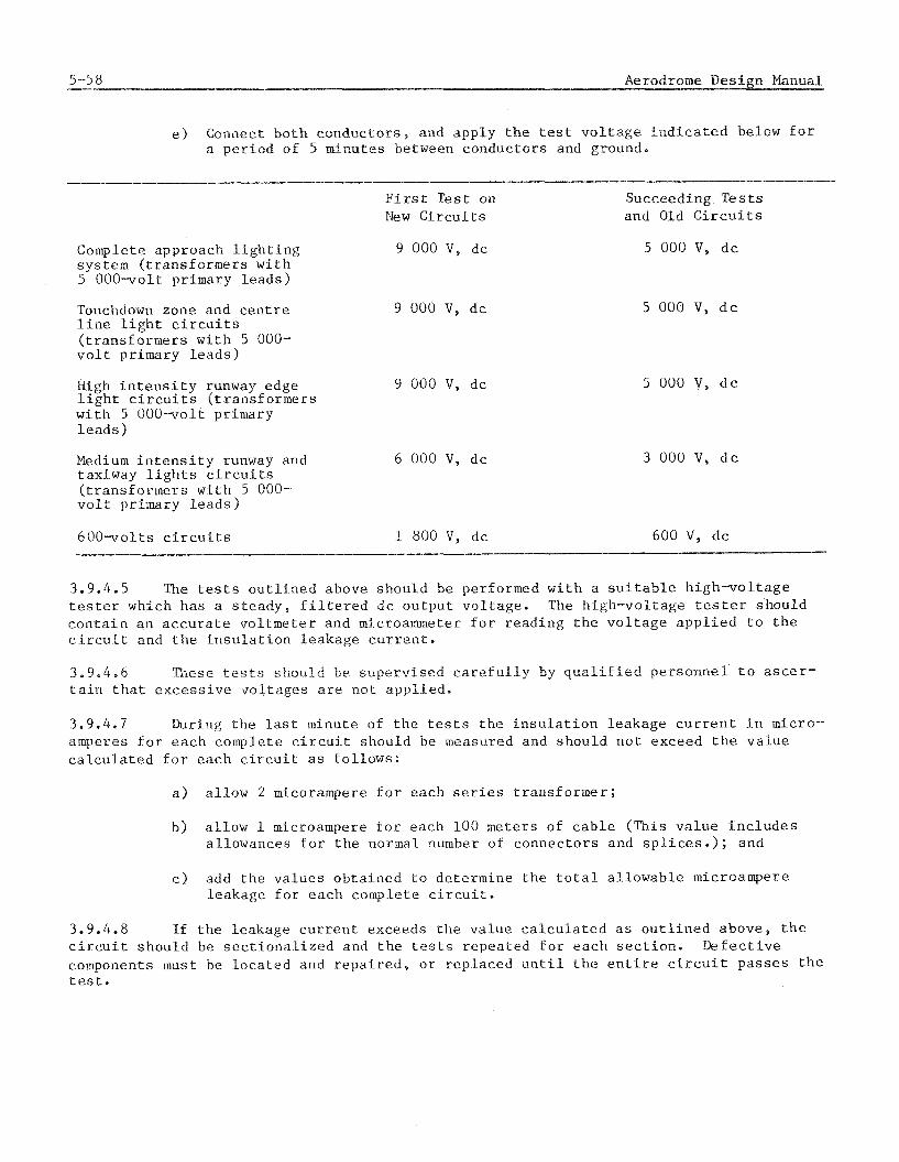
5-58 Aerodrome Des ign Manual
e ) Connect b o t h c o n d u c t o r s , and a p p l y t h e tes t v o l t a g e i n d i c a t e d below f o r a p e r i o d o f 5 minu tes between c o n d u c t o r s and ground.
- F i r s t : T e s t on Succeeding T e s t s New C i r c u i t s and Old C i r c u i t s
Complete approach l i g h t i n g sys t em ( t r a n s f o r m e r s w i t h 5 OOO-volt p r imary l e a d s )
Touchdown zone and c e n t r e l i n e l i g h t c i r c u i t s ( t r a n s f o r m e r s w i t h 5 000- v o l t p r imary l e a d s )
High i n t e n s i t y runway edge 9 000 V, d c l i g h t c i r c u i t s ( t r a n s f o r m e r s w i t h 5 OOOvol t pr imary l e a d s )
Medium i n t e n s i t y runway and 6 000 V, d c t ax iway l i g h t s c i r c u i t s ( t r a n s f o r m e r s w i t h 5 000- v o l t p r imary l e a d s )
6 0 0 - v o l t s c i r c u i t s l 800 V , d c 600 V, d c - p-
3.9.4.5 The t e s t s o u t l i n e d above s h o u l d be performed w i t h a s u i t a b l e h i g h - v o l t a g e t e s t e r which h a s a s t e a d y , f i l t e r e d d c o u t p u t v o l t a g e . The h igh -vo l t age t e s t e r s h o u l d c o n t a i n a n a c c u r a t e v o l t m e t e r and microammeter f o r r e a d i n g t h e v o l t a g e a p p l i e d t o t h e c i r c u i t and t h e i n s u l a t i o n l e a k a g e c u r r e n t .
3.9.4.5 These tests shors2.d be s u p e r v i s e d c a r e f u l l y by q u a l i f i e d p e r s o n n e l t o a s c e r - t a i n t h a t e x c e s s i v e v o l t a g e s a r e n o t a p p l i e d .
3.9.4.7 During t h e l a s t minu te of t h e t e s t s t h e i n s u l a t i o n l e a k a g e c u r r e n t i n micro- amperes f o r e a c h comple te c i r c u i t shou ld be measured and s h o u l d n o t exceed t h e v a l u e c a l c u l a t e d f o r e a c h c i r c u i t as f o l l o w s :
a ) a l l o w 2 micorampere f o r e a c h s e r i e s t r a n s f o r m e r ;
b ) a l l o w 1 microampere f o r e a c h 100 me te r s of c a b l e (Th i s v a l u e i n c l u d e s a l lowances f o r t h e normal number of c o n n e c t o r s and s p l i c e s . ) ; and
c ) add t h e v a l u e s o b t a i n e d t o d e t e r m i n e t h e t o t a l a l l o w a b l e microampere l e a k a g e f o r e a c h comple te c i r c u i t .
3.9.4.8 Lf t h e l e a k a g e c u r r e n t exceeds t h e v a l u e c a l c u l a t e d a s o u t l i n e d a b o v e , t h e c i r c u i t s h o u l d be s e c t i o n a l i z e d arid t h e t e s t s r e p e a t e d f o r e a c h s e c t i o n . I k f e c t i v e components must be l o c a t e d and r e p a i r e d , o r r e p l a c e d u n t i l t h e e n t i r e c i r c u i t p a s s e s t h e t e s t .

3.9.4.9 Make s u r e t h a t t h e t e s t v o l t a g e s p e c i f i e d i n pa rag raph 3.9.4.4 e ) i s a c t u a l l y a p p l i e d t o t h e c i r c u i t a t t h e t i m e t h e l e a k a g e c u r r e n t i s measured. The v o l t - age s h o u l d be a d j u s t e d s o t h e v o l t m e t e r r e a d s t h e d e s i r e d v a l u e b e f o r e t h e l e a k a g e c u r r e n t i s r ead . I f any d i f f i c u l t y i s encoun te red i n o b t a i n i n g t h e d e s i r e d v o l t a g e , e i t h e r t h e c i r c u i t b e i n g t e s t e d o r t h e test s e t i s d e f e c t i v e , and s h o u l d be c o r r e c t e d b e f o r e t h e t e s t i s con t inued .
3.9.4.10 On new c i r c u i t s , a r e s i s t a n c e measurement s h o u l d be made immedia t e ly a f t e r t h e c i r c u i t h a s pas sed t h e h i g h v o l t a g e t e s t s w i t h t h e t e s t s e t u sed by aerodrome maintenance . This measurement r e a d i n g t h e n can be used d u r i n g ma in tenance as a comparison w i t h f u t u r e r e a d i n g s t o de t e rmine c i r c u i t c o n d i t i o n s . Ambient t e m p e r a t u r e and wea the r c o n d i t i o n s s h o u l d be r e c o r d e d a t t h e t i m e of t e s t .
3.9.5 E l e c t r i c a l t e s t s o f o t h e r c a b l e s
3.9.5.1 Power c a b l e s r a t e d 5 000 v o l t s and more. Power c a b l e s s h o u l d b e t e s t e d as o u t l i n e d u s i n g t h e methods i n p a r a g r a p h 3.9.4.4 e x c e p t t h a t , c a b l e s r a t e d a t 5 000 v o l t s s h o u l d be t e s t e d a t 10 000 v o l t s and power c a b l e s r a t e d above 5 000 v o l t s s h o u l d be t e s t e d a t t w i c e t h e c a b l e v o l t a g e r a t i n g p l u s 1 000 v o l t s . The t e s t s h o u l d be made between conduc to r s and f rom conduc to r s t o ground w i t h t h e c a b l e ' s s h i e l d and armor grounded and f o r a p e r i o d o f n o t l e s s t h a n one minute a f t e r i n s t r u m e n t r e a d i n g s have s t a b i l i z e d . The minimum a c c e p t a b l e r e s i s t a n c e v a l u e i s 50 megohms. O r i g i n a l i n s u l a t i o n v a l u e s o f t h e c a b l e have been s u b s t a n t i a l l y reduced t o t h e s p e c i f i e d 50 megohms i n o r d e r t o compensate f o r c a b l e l e n g t h , a g i n g of cot lductor i n s u l a t i o n , and o t h e r f a c t o r s which may a f f e c t t e s t r e s u l t s b o t h b e f o r e and d u r i n g i n s t a l l a t i o n . Unless c a b l e l e n g t h s h o u l d a p p r e c i a b l y exceed 3 000 m e t r e s , no r e d u c t i o n i n t h e s p e c i f i e d i n s u l a t i o n r e s i s t a n c e s h o u l d be cons ide red . (Note. I n s u l a t i o n r e a d i n g s w i l l be e r r o n e o u s u n t i l t h e c a b l e h a s been comple t e ly cha rged by t h e measur ing i n s t r u m e n t . ) A test s h o u l d b e made f o r c o n t i n u i t y o f t h e c a b l e ' s s h i e l d o r armor. An ohmmeter t y p e i n s t r u m e n t may be used.
3.9.5.2 Power c a b l e r a t e d 600 v o l t s and below. Secondary power c a b l e s r a t e d a t 600 v o l t s and below and used f o r l i g h t i n g and power w i r i n g s h o u l d have a r e s i s t a n c e of n o t l e s s t h a n 50 megohms between c o n d u c t o r s and between c o n d u c t o r s and ground when measure- - ments a r e made a t n o t l e s s t h a n 500 v o l t s dc.
3.9.5.3 ~f~~~ i---+..l LID ~ a ~ . ~ a t i ~ i l 1 - t h e s e c a b l e s s h o u l d comply w i t h t h e f o l l o w i n g r equ i r emen t s :
S i z e c a b l e Minimum no. of a c c e p t a b l e c o n d u c t o r s
12 p a i r o r less A l l
Over 12 p a i r t o 25 p a i r , i n c l u s i v e
A l l , e x c e p t one p a i r
Over 25 p a i r A l l , e x c e p t 2 p a i r
Accep tab le conduc to r s i n c l u d e s a t i s f a c t o r y t e s t a s t o c o n t i n u i t y , f reedom f r o m s h o r t - c i r c u i t s , and a minimm of 50 megohms r e s i s t a n c e betwen c o n d u c t o r s and f rom e a c h con- d u c t o r t o grounded s h i e l d when t e s t e d a t n o t l e s s t h a n 500 v o l t s dc .
3.9.5.4 Coaxia l cab les . Radio f requency c a b l e s shou ld be t e s t e d f o r i n s u l a t i o n and loop r e s i s t a n c e p r i o r t o i n s t a l l a t i o n and t h e r e s u l t s recorded. The i n s u l a t i o n t e s t should be made between t h e c e n t r e conductor and s h i e l d w i t h a 5 0 0 v o l t d c i n s t r u m e n t . The loop r e s i s t a n c e t e s t shou ld be a l s o made a s above, but w i t h t h e c e n t r e conduc to r s s h o r t e d t o t h e s h i e l d a t t h e f a r end of t h e c a b l e . This t e s t may be made w i t h a b r i d g e , ohmmeter, o r o t h e r s u i t a b l e ins t rument . A f t e r i n s t a l l a t i o n , t h e conductor- to-shie ld and conductor-to-grond r e s i s t a n c e should exceed 5 0 megohms when measured a t 5 0 0 v o l t s dc . Loop r e s i s t a n c e shou ld be w i t h i n p l u s o r minus 1 0 per c e n t of t h e measured v a l u e s p r i o r t o i n s t a l l a t i o n , e.g. measured r e s i s t a n c e pe r 1 0 0 0 metres of c a b l e on r e e l , m u l t i p l i e d by each 1 000 metres and f r a c t i o n the reof of i n s t a l l e d c a b l e . S h i e l d - t o ground r e s i s t - ance should a l s o be measured and t h e r e s u l t s recorded.
3.9.5.5 Coaxia l c a b l e , p r e s s u r i z e d . Upon complet ion of t h e c a b l e i n s t a l l a t i o n , t h e f o l l o w i n g t e s t should be made:
a ) E l e c t r i c a l t e s t . A h i g h - v o l t a g e i n s u l a t i o n t e s t e r wi th microammeter cu r ren t - l eakage meter should be used and 3 0 0 0 v o l t s d c a p p l i e d between t h e i n n e r and o u t e r conductors f o r a minimum p e r i o d of t h r e e minutes . While t h i s v o l t a g e i s a p p l i e d no n o t i c a b l e c u r r e n t shou ld f l o w between t h e conductors a f t e r cha rg ing c u r r e n t h a s s t a b i l i z e d .
b ) Nitrogen gas t e s t . Nitrogen gas a t t h e s p e c i f i e d p r e s s u r e s h o u l d b e a p p l i e d t o t h e c a b l e , t h e g a s v a l v e c l o s e d , and ambient t e m p e r a t u r e recorded. Six s u c c e s s i v e , hour ly measurement of p r e s s u r e s h o u l d be t aken and recorded. A f t e r t h e s i x t h measurement i s t a k e n and a f t e r a t ime i n t e r v a l of about 24 hours , a s e v e n t h measurement s h o u l d be made. I f v a r i a t i o n s i n gas p r e s s u r e a r e due on ly t o changes i n ambient temper- a t u r e , t h e l e n g t h of c a b l e i s a c c e p t a b l e . A t empera tu re c o r r e c t i o n f a c t o r of 0.017 p e r degree C should be used.
3,9,6.X ' f ie supply v o l t a g e and t h e i n p u t t a p of t h e r e g u l a t o r shou ld he checked t o s e e t h a t they correspond.
3.9.6.2 -. . wrth load d i sconnec ted , e n e r g i z e t h e r e g u l a t o r once, and watch t h e open- c i r c u i t p r o t e c t o r t o s e e t h a t i t deenerg izes t h e r e g u l a t o r w i t h i n 2 o r 3 seconds .
a ) Connect t h e load c i r c u i t a f t e r i t h a s been checked f o r opens and ground a s r e q u i r e d i n paragraphs 3.9.4.3 and 3.9.4.4 and i n s p e c t e d t o s e e t h a t a l l t r ans fo rmers a r e p r o p e r l y lanped.
b ) Obtain a v o l t m e t e r and a n ammeter w i t h a n e r r o r of n o t more t h a n L 1 p e r c e n t of f u l l s c a l e , and s imul taneous ly measure i n p u t v o l t a g e and ou tpu t c u r r e n t (connect t h e ammeter t o t h e t e r m i n a l s of a n i s o l a t i n g t ransform- e r i n s e r t e d i n t o t h e ou tpu t c i r c u i t of t h e r e g u l a t o r ) f o r e a c h i n t e n s i t y s e t t i n g t ap .
c ) Use a r e c o r d i n g vo l tmete r o r t a k e read ings d u r i n g both day and n i g h t a t s u f f i c i e n t i n t e r v a l s t o o b t a i n a n average supply v o l t a g e .
d ) I f r e g u l a t o r h s s i n p u t v o l t a g e t a p s , s e l e c t t h e t a p w h i c h most n e a r l y corresponds t o average supply vo l t age . The o u t p u t c u r r e n t f o r each i n t e n s i t y s e t t i n g t a p shou ld be wfchfn IL 2 pe r c e n t of t h e nameplate values a f t e r any necessary supply v o l t a g e c o r r e c t i o n i s made.

3.9.6,3 I n a l l c u r r e n t r e g u l a t o r s which have i n p u t v o l t a g e t a p s , t h e o u t p u t c u r r e n t w i l l vary i n p r o p o r t i o n t o i n p u t v o l t a g e changes. I f a supply v o l t a g e of 2 350 i s a p p l i e d t o t h e 2 4 0 0 v o l t t a p , t h e o u t p u t c u r r e n t v a l u e s shou ld be 2 p e r c e n t below t h e nameplate va lues .
3.9.6.4 Regulators which have au tomat ic supply v o l t a g e c o r r e c t i o n i n l i e u of i n p u t t a p s do no t change t h e ou tpu t c u r r e n t a s t h e supply v o l t a g e v a r i e s .
a ) I f t h e o u t p u t c u r r e n t on f u l l i n t e n s i t y d e v i a t e s from t h e namepla te v a l u e by more than 2 p e r c e n t (and i f t h e r e g u l a t o r is n o t over loaded) , t h e i n t e r n a l adjus tment should be checked, a s d e s c r i b e d o n t h e r e g u l a t o r i n s t r u c t i o n p l a t e . S ince t h e adjus tment may be d e l i c a t e , i t i s recommended t h a t a d e v i a t i o n of +- 5 p e r c e n t he a l lowed on lower s e t - t i n g s b e f o r e a t t e m t i n g t o r e a d j u s t t h e r e g u l a t o r .
b) Furthermore, a check shou ld be made t o s e e whether t h e ad jus tment had been changed purposely f o r a n unusual l o c a l f l i g h t o p e r a t i o n a l requirement.
3.9.7.1 The fo l lowing t e s t shou ld h e l p l o c a t e t h e f a u l t i n t h e e v e n t t h a t t h e t e s t s i n d i c a t e improper opera t ion .
3.9.7.2 Disconnect t h e l o a d , s h o r t - c i r c u i t r e g u l a t o r o u t p u t t e r m i n a l s th rough a n ammeter, and measure o u t p u t c u r r e n t . I f measured v a l u e s a r e e q u a l t o o r s l i g h t l y h i g h e r than nameplate v a l u e s , t h e r e g u l a t o r i s o p e r a t i n g s a t i s f a c t o r i l y and t h e l o a d c i r c u i t shou ld be checked f o r f a u l t s .
3.9.7.3 Connect t h e load c a b l e s ( a f t e r load c i r c u i t has been checked f o r opens and grounds, a s s p e c i f i e d i n paragraphs 3.9.4.3 and 3.9.4.4 and i n s p e c t e d t o s e e t h a t a l l t r ans fo rmers a r e p r o p e r l y lamped), and measure o u t p u t c u r r e n t and o u t p u t v o l t a g e s i m u l t a n e s u s l y w i t h t h e regulator operacii ig on i h e h i g h e s t i n t e n s i t y s e t t i n g . The s i g n i f i c a n c e of t h e read ings i s a s fo l lows :
a ) S a c i s f a c t o r y o p e r a t i o n i s i n d i c a t e d by c o r r e c t o u t p u t c u r r e n t and a n o u t p u t v o l t a g e which i s s l i g h t l y h i g h e r t h a n t h a t e s t i m a t e d f o r t h e l o a d , but which does no t exceed t h e r a t e d o u t p u t v o l t a g e . The v o l t a g e r e q u i r e d f o r t h e load may be e s t i m a t e d by m u l t i p l y i n g t h e i s o l a t i n g t r ans fo rmer primary v o l t a g e a t r a t e d load ( w a t t s d i v i d e d by pr imary c u r r e n t ) by t h e number of t r ans fo rmers connected i n s e r i e s i n t h e load c i r c u i t .
b) A c o r r e c t o u t p u t c u r r e n t w i t h an o u t p u t v o l t a g e a p p r e c i a b l y l e s s t h a n t h e e s t i m a t e d load v o l t a g e i n d i c a t e s complete o r p a r t i a l s h o r t i n g of t h e load.
c ) A c o r r e c t o u t p u t c u r r e n t wi th a n o u t p u t v o l t a g e exceed ing t h e r a t e d l o a d o u t p u t v o l t a g e i n d i c a t e s a n overload.
d ) A reduced o u t p u t c u r r e n t wi th an o u t p u t v o l t a g e i n d i c a t i n g a n o v e r l o a d i s p o s s i b l y caused by a poor connect ion i n t h e l o a d c i r u i t . The r e g u l a t o r should be deenergized immediately t o p reven t damage.
e ) A reduced o u t p u t c u r r e n t w i t h a n o u t p u t v o l t a g e n o t exceed ing t h e r a t e d o u t p u t v o l t a g e i n d i c a t e s a f a u l t y r e g u l a t o r o r reduced s u p p l y v o l t a g e .
f ) A z e r o o u t p u t c u r r e n t w i t h e x c e s s i v e o u t p u t v o l t a g e i n d i c a t e s a n open i n t h e l o a d c i r c u i t and f a i l u r e of t h e open-c i rcu i t p r o t e c t o r i n t h e r e g u l a t o r . I n t h i s c a s e , t h e r e g u l a t o r must be deenergized immediate ly t o p reven t s e r i o u s damage.
g ) CAUTION: The o p e n - c i r c u i t p r o t e c t o r of t h e r e g u l a t o r must n o t be d e a c t i v a t e d o r by-passed d u r i n g t h e s e t e s t s .
3.9.8 E l e c t r i c a l tests of o t h e r equipment
3.9.8.1 Measure t h e i n p u t and ou tpu t v o l t a g e s and c u r r e n t s and de te rmine t h e l o a d s of t h e connected c i r c u i t s . Check t o determine i f t h e s e v o l t a g e s and l o a d s a r e w i t h i n t h e manufac tu re r ' s r a t i n g of t h e equipment. Record t h e s e measurements f o r f u t u r e r e f e r e n c e d u r i n g maintenance o r f o r m o d i f i c a t i o n of t h e c i r c u i t .
T e s t s of moni tors
3.9.9.1 A f t e r t h e t e s t s l i s t e d above have been completed and t h e sys tem i s f u n c t i o n - i n g a s des igned , monitors should be t e s t e d by s i m u l a t i n g such f a i l u r e s a s o p e n - c i r c u i t s , s h o r t - c i r c u i t s , grounds, f a i l u r e of l i g h t s , l o s s of power i n both t h e l i g h t i n g c i r c u i t s and t h e c o n t r o l c i r c u i t s , and obse rv ing t h e performance of t h e monitor. Moni tors which f a i l t o perform a s in tended shou ld be r e p a i r e d b e f o r e t h e sys tem i s accep ted .

4.1 GENERAL KEQUIKEMENTS
4.1.1 I n i t i a l c o n s i d e r a t i o n s
4.1.1.1 I n s t a l l a t i o n of e l e c t r i c a l c a b l e s underground i s expens ive and t echn iques t o a s s u r e long and e f f e c t i v e s e r v i c e w i t h a minimum of maintenance shou ld be used. A l l work shou ld be done by exper ienced pe r sonne l r e g u l a r l y engaged i n t h e i r t y p e of work. Most underground c a b l e s w i l l be l o c a t e d on, o r very c l o s e t o , t h e manoeuvring a r e a of t h e aerodrome. Hence, a t a c t i v e aerodromes g r e a t c a r e must be e x e r c i s e d t o e n s u r e t h a t t h e i n s t a l l a t i o n does n o t p r e s e n t a hazard t o a i r c r a f t o r t o t h e i n s t a l l e r s .
4.1.2 P r e c o n s t r u c t i o n arrangements
4.1.2.1 Obtain p r i o r approva l of t h e e n g i n e e r i n charge f o r t h e m a t e r i a l s , workmen, t ime of day o r n i g h t f o r t h e work, method and procedures f o r t h e i n s t a l l a t i o n , and procedure f o r any temporary o r permanent r e p a i r s t o be made. Arrange f o r c o - o r d i n a t i n g t h e e f f o r t w i t h A i r T r a f f i c C o n t r c l i f i t may be involved. C a r e f u l l y de te rmine and mark t h e r o u t e f o r t h e c a b l e s . Take a l l r e a s o n a b l e p r e c a u t i o n s t o p r o t e c t e x i s t i n g underground u t i l i t i e s such a s f u e l t anks , wa te r l i n e s , b u r i e d c o n t r o l and power c a b l e s , e t c . A l l known u t i l i t i e s and power and c o n t r o l c a b l e s l e a d i n g t o and f rom any o p e r a t i n g f a c i l i t y should be marked i n t h e f i e l d b e f o r e any work i n t h e g e n e r a l v i c i n i t y i s s t a r t e d . T h e r e a f t e r and throughout t h e e n t i r e t ime of c o n s t r u c t i o n t h e y s h o u l d be p r o t e c t e d from any p o s s i b l e damage. Any underground c a b l e s which a r e damaged d u r i n g i n s t a l l a t i o n should be immediately r e p a i r e d w i t h e q u a l q u a l i t y m a t e r i a l .
4.1.3 Methods of i n s t a l l a t i o n
4,1,3.1 There a r e two methods of i n s t a l l i n g underground e l e c t r i c a l c a b l e s , by d i r e c t b u r i a l o r i n duc t ( c o n d u i t ) . These methods a r e d i s c u s s e d below.
4.2 UIUCT UUKXAL OF CABLE
4.2.1.1 The major s t e p s of i n s t a l l i n g e l e c t r i c a l c a b l e s by d i r e c t b u r i a l a r e t r e n c h i n g , placement of t h e c a b l e , and b a c k f i l l i n g .
4.2.2 Trenching
4.2.2.1 Basic requirements . Unless r e q u i r e d o t h e r w i s e , a l l c a b l e s i n t h e s a n e l o c a t i o n and running i n t h e same g e n e r a l d i r e c t i o n shou ld be i n s t a l l e d i n t h e same t rench . Walls of t r e n c h e s shou ld be e s s e n t i a l l y v e r t i c a l s o t h a t a minimum of s h o u l d e r s u r f a c e i s d i s tu rbed . The bottom s u r f a c e of t r e n c h e s shou ld be e s s e n t i a l l y smooth and f r e e from c o a r s e aggrega te . I f p o s s i b l e , t r e n c h e s shou ld be opened o n l y t o t h e e x t e n t t h a t c a b l e s can be i n s t a l l e d and t h e t r e n c h c losed i n t h e same working day. Where t u r f i s w e l l e s t a b l i s h e d and t h e sod can be reanved, i t shou ld h e c a r e f u l l y s t r i p p e d and p r o p e r l y s t o r e d .
4.2.2.2 The t r e n c h dep th should be n o t l e s s t h a n 5 cm below t h e l e v e l of t h e lowes l e s shou ld be a minimum of 5 0 cm below t h e f i n i s h e d g rade when on t h e aerodrome p r o p e r t y and 7 5 cm below t h e f i n i s h e d g rade when o f f t h e aerodrome proper ty . I f c a b l e s a r e t o be placed a t more than one l e v e l , t h e v e r t i c a l s e p a r a t i o n should be t h e same a s t h e h o r i z o n t a l s e p a r a t i o n i n d i c a t e d i n paragraph 4.2 .3 , excep t v e r t i c a l s e p a r a t i o n of c o n t r o l and t e l ephone c a b l e s and of low v o l t a g e s power c a b l e s should be n o t l e s s than 6 cm. The ground w i r e o r c o u n t e r p o i s e should be a minimum of 15 cm above t h e uppermost l a y e r of c a b l e s . Trench depths should a l low f o r t h e s e v e r t i c a l s e p a r a t i o n s .
4.2.2.3 Heavy t r a f f i c a r e a s . Cables shou ld n o t be d i r e c t b u r i e d under paved a r e a s , roadways, r a i l r o a d t r a c k s , o r d i t c h e s . In t h e s e a r e a s t h e c a b l e shou ld be i n s t a l l e d i n concrete-encased d u c t s o r i n r i g i d s t e e l condu i t .
4.2.2.4 Areas of rocks . Where rock excava t ion i s encountered t h e rock s h o u l d b e removed t o a dep th of a t l e a s t 8 cm below t h e r e q u i r e d c a b l e d e p t h and i t s h o u l d be rep laced w i t h bedding m a t e r i a l of e a r t h o r sand c o n t a i n i n g no minera l a g g r e g a t e p a r t i c l e s l a r g e r than S mm i n d iameter . When s o l i d rock i s encountered, a l t e r n a t i v e s such a s r e r o u t i n g t h e t r e n c h o r i n s t a l l a t i o n i n r i g i d s t e e l condu i t shou ld b e considered.
4.2.2.5 Trench width . Trench width f o r a s i n g l e c a b l e shou ld be n o t l e s s t h a n 1 5 cm. Where more than one c a b l e i s l o c a t e d i n a t r e n c h , t h e t r e n c h w i d t h shou ld be a d j u s t e d s o t h a t t h e s e p a r a t i o n s g iven below can be mainta ined.
4.2.3 Separa t ion between c a b l e s
a ) Power c a b l e s , of t h e same c i r c u i t , may be l a i d s i d e by s i d e i n t h e t r e n c h wi thou t s e p a r a t i o n , except a s noted below. S e r i e s l i g h t i n g c a b l e s may be considered a s of t h e same c i r c u i t .
b) Power c a b l e s of t h e same o r d i f f e r e n t c i r c u i t s of l e s s t h a n 600 v o l t s , may be l a i d t o g e t h e r i n t h e same t r e n c h w i t h o u t hor izonlsa i s e p a r a t i o n .
c ) Power c a b l e s of d i f f e r e n t c i r c u i t s w i t h v o l t a g e s between 600 and 5 000 v o l t s should be s e p a r a t e d a miniimlim of 10 cm.
d ) A l l power c a b l e s , 5 000 v o l t s and below, shou ld be s e p a r a t e d f rom a l l c o n t r o l , t e l ephone , and c o a x i a l t y p e c a b l e s by a minimum of 1 5 cm.
e ) Power c a b l e s , of more than 5 000 v o l t s , shou ld be s e p a r a t e d f rom a l l o t h e r c a b l e s by a minimum of 3 0 cm.
f ) Con t ro l , t e l ephone , and c o a x i a l c a b l e s may be l a i d i n t h e t r e n c h w i t h o u t h o r i z o n t a l s e p a r a t i o n from each o t h e r .
g ) V e r t i c a l s e p a r a t i o n s should be s i m i l a r t o t h o s e g iven i n a ) th rough f ) excep t t h a t c a b l e s which do not r e q u i r e h o r i z o n t a l s e p a r a t i o n should be s e p a r a t e d a minimum of 6 cm v e r t i c a l l y . No c a b l e shou ld d i r e c t l y over- l a p ano the r c a b l e because compacting may damage t h e c a b l e .
h ) Ground w i r e s and coun te rpo i ses should be approximate ly 15 cm above t h e uppermost l e v e l of t h e c a b l e s .
4.2.4 I n s t a l l a t i o n of d i r e c t - b u r i a l c a b l e s
4.2.4.1 . Before p l a c i n g any c a b l e s , b a c k f i l l and compact a 5 cm l a y e r of e i t h e r e a r t h o r sand c o n t a i n i n g no m a t e r i a l a g g r e g a t e p a r t i c l e s l a r g e r than 6 mm i n d iameter .
4.2.4.2 Wherever p o s s i b l e , c a b l e shou ld be run i n one p i e c e , wi thou t s p l i c e s , from connec t ion t o connect ion. Use t h e l o n g e s t p r a c t i c a b l e l e n g t h s of c a b l e i n o r d e r t o minimize s p l i c i n g requirements . When c a b l e c u t t i n g i s r e q u i r e d , c a b l e ends should be e f f e c t i v e l y s e a l e d a g a i n s t mois tu re immediately a f t e r c u t t i n g . Bends of a r a d i u s l e s s t h a n e i g h t t imes t h e d iamete r f o r rubber- o r p l a s t i c - c o v e r e d c a b l e and twelve t imes t h e d iamete r f o r meta l l ic-armored c a b l e shou ld n o t be made. Cable t h a t has been kinked should not be i n s t a l l e d . A man shou ld be s t a t i o n e d a t t h e r e e l t o obse rve and r e p o r t any i r r e g u l a r i t i e s i n t h e c a b l e when t h e c a b l e i s being unree led . Cable f o r d i r e c t e a r t h b u r i a l should be unree led i n p l a c e i n t h e open t r e n c h o r u n r e e l e d n e a r t h e t r e n c h and c a r e f u l l y p laced i n t h e t r e n c h bottom. P u l l i n g t h e c a b l e i n t o t h e t r e n c h by d ragg ing over t h e ground shou ld n o t be pe rmi t t ed .
4.2.4.3 Cable s l a c k loops . A c a b l e s l a c k loop of approximate ly one met re should be l e f t on each end of c a b l e r u n s , and a t a l l p o i n t s where c a b l e connec t ions a r e brought above ground. The s l a c k loop shou ld be i n s t a l l e d a t t h e same minimum d e p t h a s t h e c a b l e run. Loops should have bends w i t h a n i n n e r r a d i u s n o t l e s s than twelve t imes t h e o u t s i d e d iamete r of t h e c a b l e . Where c a b l e i s brought above ground, a d d i t i o n a l s l a c k should be l e f t above ground. A t a l l c a b l e s p l i c e s , p rov ide s l a c k l o o p s f r e e of bends a t t h e s p l i c e o r w i t h i n 3 0 cm of t h e ends of t h e s p l i c e .
4.2.4.4 F i n a l b a c k f i l l i n g . A f t e r t h e c a b l e h a s been i n s t a l l e d , t h e t r e n c h should be b a c k f i l l e d a s fo l lows :
a ) B a c k f i l l s e p a r a t i n g c a b l e s shou ld be f i r m l y tamped i n p l a c e . The c a b l e s e p a r a t i o n s g i v e n i n 4.2.3 .should be maintained. These s e p a r a t i o n s may be e i t h e r h o r i z o n t a l , v e r t i c a l , o r a combination of t h e two.
b ) The f i r s t l a y e r of b a c k f i l l i n g shou ld be n o t l e s s than 7.5 cm deep, l o o s e measurement, and shou ld be e i t h e r e a r t h o r sand c o n t a i n i n g no m a t e r i a l a g g r e g a t e p a r t i c l e s l a r g e r t h a n 6 mm d iamete r . Th i s l a y e r shou ld no t be compacted, excep t f o r tamping t o m a i n t a i n s e p a r a t i o n of c a b l e s .
c ) The second l a y e r should be n o t l e s s than 12 cm deep, l o o s e measurement, and shou ld c o n t a i n no p a r t i c l e s l a r g e r than 25 mm d iamete r .
d ) The remainder of t h e b a c k f i l l i n g may be excavated o r imported m a t e r i a l and shou ld n o t c o n t a i n s t o n e s o r aggrega te l a r g e r t h a n 1 0 0 mm i n d iameter . The t h i r d and subsequent l a y e r s of t h e b a c k f i l l i n g should n o t exceed 2 0 cm i n maximum dep th , l o o s e measurement. The second and subsequent l a y e r s shou ld be thoroughly tamped and compacted t o a t l e a s t t h e d e n s i t y of t h e a d j a c e n t und i s tu rbed s o i l . I f n e c e s s a r y t o o b t a i n t h e d e s i r e d compaction, t h e b a c k f i l l m a t e r i a l may be mois tened o r a e r a t e d a s r equ i red . Trenches shou ld n o t be e x c e s s i v e l y wet and should n o t c o n t a i n poo l s of water d u r i n g t h e b a c k f i l l i n g o p e r a t i o n s . The t r e n c h shou ld be complete ly b a c k f i l l e d and tamped l e v e l w i t h t h e a d j a c e n t s u r f a c e .
e ) When sod i s t o be p laced over t h e t r e n c h , t h e b a c k f i l l i n g s h o u l d be s topped a t a dep th e q u a l t o t h e t h i c k n e s s of t h e sod t o be used. Any excess excavated m a t e r i a l should be removed.
Where sod has been removed i t shou ld be r e p l a c e d a s soon a s p o s s i b l e a f t e r t h e b a c k f i l l i n g i s completed. A l l a r e a s d i s t u r b e d by t h e t r e n c h i n g , s t o r i n g of d i r t , c a b l e l a y i n g , pad c o n s t r u c t i o n , and o t h e r work should be r e s t o r e d t o i t s o r i g i n a l c o n d i t i o n . The r e s t o r a t i o n should i n c l u d e any necessa ry t o p s o i l i n g , f e r t i l i z i n g , l i m i n g , s e e d i n g , sodding, s p r i g g i n g , o r nrulching. I f t r e n c h i n g c u t s a r e made through paved a r e a s , t h e c u t s , a f t e r p roper b a c k f i l l i n g , should be r e s u r f a c e d w i t h paving s i m i l a r t o t h e o r i g i n a l paving. Resurfaced c u t s should be l e v e l w i t h t h e o r i g i n a l paving, f r e e from c r a c k s , and c a p a b l e of wi ths tand ing t r a f f i c l o a d s imposed wi thou t s e t t l i n g o r c r a c k i n g .
4.3 INSTALLATION OF DUCTS (CONDUIT)
I n s t a l l a t i o n t echn iques and procedures
4.3.1, l S e l e c t i o n of r o u t e s . Duct-l ine r o u t e s shou ld be s e l e c t e d t o b a l a n c e maxirnum f l e x i b i l i t y w i t h minimum c o s t and t o avo id founda t ions f o r f u t u r e b u i l d i n g s and o t h e r s t r u c t u r e s . Where i t may be necessa ry t o r u n communication l i n e s a l o n g w i t h e l e c t r i c power d i s t r i b u t i o n l i n e s , two i s o l a t e d systems i n s e p a r a t e rnanhole compartments should be provided. Where p o s s i b l e , d u c t s should be i n s t a l l e d i n t h e same c o n c r e t e envelope. E l e c t r i c and communication d u c t s shou ld be k e p t c l e a r of a l l o t h e r underground u t i l i t i e s , e s p e c i a l l y h igh- temperature wa te r o r s t eam p ipes .
4.3 .1 ,2 Duct m a t e r i a l s . Acceptable s t a n d a r d m a t e r i a l s f o r d u c t s i n c l u d e f i b e r , asbestos-cement, t i l e , and p l a s t i c . K g i d s t e e l condu i t may a l s o be i n s t a l l e d below grade and should be provided w i t h f i e l d o r f a c t o r y a p p l i e d c o a t i n g s where r e q u i r e d .
4.3.1.3 S i z e of d u c t s . S ize of c o n d u i t s i n a d u c t bank shou ld be n o t less t h a n 10 cm i n s i d e diameter excep t t h a t d u c t s f o r commnica t ion l i n e s w i t h a minimum diameter of 7.5 cm a r e accep tab le .
4.3.1.4 I n s t a l l a t i o n of d u c t s wi thou t c o n c r e t e encasement. Trenches f o r s i n g l e - d u c t l i n e s shou ld be no t l e s s than 15 cm nor more than 30 cm wide, and t h e t r e n c h f o r two o r more d u c t s i n s t a l l e d a t t h e same l e v e l shou ld be p r o p o r t i o n a t e l y wider . Trench bottoms f o r d u c t s wi thout c o n c r e t e encasement s h o l d be made t o confo.rm a c c u r a t e l y t o g rade s o a s t o p rov ide uniform suppor t f o r t h e duc t a l o n g i t s e n t i r e l e n g t h . A l a y e r of f i n e e a r t h m a t e r i a l a t l e a s t 10 cm t h i c k ( l o o s e measurement) should be p laced i n t h e bot tom of t h e t r e n c h a s bedding f o r t h e duc t . The bedding m a t e r i a l shou ld c o n s i s t of s o f t d i r t , sand, o r o t h e r f i n e f i l l , and i t should c o n t a i n no p a r t i c l e s l a r g e r than 6 mn d iamete r . The bedding m a t e r i a l should be tamped u n t i l f i rm. When two or rnore d u c t s a r e i n s t a l l e d i n t h e same t r e n c h wt thout c o n c r e t e encasement, they shou ld be spaced no t less t h a n 5 cm a p a r t (measured from o u t s i d e w a l l t o o u t s i d e w a l l ) i n a h o r i z o n t a l d i r e c t i o n o r o o t l e s s t h a n 15 cm a p a r t i n a v e r t i c a l d i r e c t i o n . Rigid s t e e l ancl heavy-wal l c o n d u i t may be d i r e c t e a r t h bur ied . A l l o t h e r c o n d u i t s shou ld be encased.
4.3.1.5 L n s t a l l a t i o n of d u c t s encased i n c o n c r e t e . Al.]. d u c t s i n s t a l l e d i n c o n c r e t e encasement s h u u l d be p l a c e d on a Layer of concrete no t less t h a n 9 - 5 c m thick. Where

(measured from o u t s i d e w a l l t o o u t s i d e w a l l ) . A s t h e duc t l a y i n g p r o g r e s s e s , c o n c r e t e n o t l e s s t h a n 7.5 cm t h i c k should be p laced around t h e s i d e s and top of t h e d u c t bank. Flared ends of d u c t s o r coup l ings shou ld be i n s t a l l e d f l u s h w i t h t h e c o n c r e t e encasement o r i n s i d e w a l l s of manholes o r handholes. I n t e r l o c k s p a c e r s should be used a t no t more than 1.5 metre spac ing t o i n s u r e uniform spac ing between duc t s . J o i n t s i n a d j a c e n t d u c t s should be s t aggered a minimum of 6 0 cm a p a r t and should be made waterproof p r i o r t o c o n c r e t i n g . No duc t having a d e f e c t i v e j o i n t should be i n s t a l l e d . Concrete-encased d u c t o r r i g i d s t e e l condui t should be i n s t a l l e d s o t h a t t h e t o p of t h e c o n c r e t e envelope o r condui t i s no t l e s s t h a n 4 0 cm below t h e bottom of t h e paving where i t i s i n s t a l l e d under roadways, r a i l r o a d s , runways, taxiways, o t h e r paved a r e a s , and d i t c h e s and no t l e s s t h a n 4 0 cm below t h e f i n i s h e d grade elsewhere.
4.3.1.6 Grounding bushings. Mhere r i g i d s t e e l condui t e n t e r s o r l e a v e s a manhole o r handhole a grounding bushing should be provided f o r a l l condui t s .
4.3.1.7 Arrangement of d u c t banks. An arrangement of two d u c t s wide o r h i g h shou ld be used f o r b e s t h e a t d i s s i p a t i o n . Correspondingly, t h e duc t banks may be s e v e r a l d u c t s h igh o r wide. (This may be imposs ib le where a l a r g e number of d u c t s a r e invo lved . ) The v e r t i c a l two conduit-wide arrangement e n a b l e s t h e c a b l e s t o be more e a s i l y racked on manhole w a l l s bu t may n o t be a s economical a s t h e h o r i z o n t a l two condui t -high arrangement. For dimensions and arrangement of duc t banks, s e e F igure 4-1.
4.3.1.8 Drainage. A l l duc t l i n e s shou ld be l a i d s o a s t o s l o p e toward handholes , manholes and duct ends f o r dra inage. Grades should be a t l e a s t 2.5 m i l l i m e t r e s pe r metre. Where i t i s n o t p r a c t i c a b l e t o mainta in t h e s l o p e a l l one way, t h e d u c t l i n e s may be s loped from t h e c e n t e r i n both d i r e c t i o n s toward manholes, handholes , o r duc t ends. Pockets o r t r a p s where mois tu re may accum~i la te should be avoided.
4.3.1.9 P u l l wire . Each s p a r e duc t i n s t a l l e d should be provided w i t h a copper-clad s t e e l p u l l w i r e of n o t l e s s than 5 mm2 i n a r e a * The open ends of t h e s p a r e d u c t s should be plugged w i t h removable t a p e r e d plugs . The plug should s e c u r e t h e p u l l w i r e f i r m l y .
4.3.1.10 S u f f i c i e n t d u c t s f o r planned i n s t a l l a t i o n s , f u t u r e expansion, p l u s a minimum of 2 5 p e r c e n t of s p a r e d u c t s , should be inc luded f o r a l l new underground systems.
4.4 MANHOLES AND HANDHOLES
4.4.1 S e l e c t i o n
4.4.1.1 Fac tors b e a r i n g on t h e cho ice of manholes and handholes a r e number, d i r e c t i o n , and l o c a t i o n of duc t runs; c a b l e rack arrangements; method of d r a i n a g e ; adequacy of work space ( e s p e c i a l l y i f equipment i s t o be i n s t a l l e d i n t h e manhole); and t h e s i z e of t h e opening r e q u i r e d t o i n s t a l l and remove equipment.

SINGLE DUCT
ELECTRIC OR COMMUNICATION COMBINED ELECTRIC (E) AND COMMUNlCATlON (C)
1.5 cm TYPICAL
1.25 cm BARS AT 15 cm TO 20 cm ON CENTRES$
7.5 cm TYPICAL (2.5 cm WIRE HOOP) APPROXIMATELY 20 cm
ON CENTRES~
REINFORCED DUCT BANKS
1. WHERE REINFORCEMENT IS PROVIDED UNDER RAILROAD TRACKS I T SHOULD EXTEND AT LEAST 3.5 m BEYOND THE OUTER RAILS.

4.4.2 Locat ion
4.4.2,1 Manholes o r handholes s h o u l d be p laced where r e q u i r e d f o r connec t ions o r s p l i c e s and where c o n f l i c t w i t h o t h e r u t i l i t i e s w i l l be avoided* Manhole s e p a r a t i o n shou ld n o t exceed 200 met res on s t r a i g h t r u n s and 100 metres on curved d u c t runs . Spacing shou ld be dec reased where necessa ry t o p reven t i n s t a l l a t i o n damage d u r i n g p u l l i n g of c a b l e s . S t r a i n shou ld be limi.ted d u r i n g i n s t a l l a t i o n t o a p o i n t t h a t w i l l n o t damage c a b l e i n s u l a t i o n o r deform t h e c a b l e ( s e e Tab le 4-1).
4.4.3 Stubs
4.4.3.1 It i s good p r a c t i c e t o p rov ide a set of two o r more s p a r e s t u b s ( s h o r t l e n g t h s of d u c t s l e a d i n g o u t from t h e manhole) s o t h a t t h e manhole w a l l need n o t be d i s t u r b e d when a f u t u r e e x t e n s i o n i s made. The s t u b s shou ld be plugged on b o t h ends .
4.4.4 Hardware
4.4.4.1 Hardware a p p l i c a b l e t o t h e i n s t a l l a t i o n s h o u l d be chosen. Where f l a r e d e n d s of d u c t s a r e provided, cable-duct s h i e l d s a r e necessa ry only f o r p r o t e c t i o n of m e t a l l i c - s h e a t h e d c a b l e s .
Two-section manholes
4.4.5.1 T w o s e c t i o n manholes should be used t o m a i n t a i n s e p a r a t i o n of t h e c i r c u i t s where e l e c t r i c power and communication l i n e s a r e i n s t a l l e d i n t h e same d u c t bank o r use t h e same manhole.
4.5 INSTALLATION OF UNDERGROUND CABLES
4.5.1 P r e ~ a r a t i o n of d u c t s
4.5.1.1 A f t e r t h e d u c t i n s t a l l a t i o n i s completed, t h e c a b l e s a r e i n s t a l l e d by drawing o r p u l l i n g i n t o t h e d u c ~ s . The d u c t shou ld be open, con t inuous , and c l e a r of d e b r i s b e f o r e t h e c a b l e i s i n s t a l l e d . The c a b l e shou ld be i n s t a l l e d i n a manner t o p r e v e n t harmful s t r e t c h i n g of t h e conductor , i n j u r y t o t h e i n s u l a t i o n , o r damage t o t h e o u t e r p r o t e c t i v e cover ing . The ends of a l l c a b l e s shou ld be s e a l e d w i t h m o i s t u r e s e a l t a p e b e f o r e i n s t a l l i n g , and t h e y shou ld be kep t s e a l e d u n t i l connec t ions are made. Where more than one c a b l e i s t o be i n s t a l l e d i n a d u c t o r c o n d u i t , a l l c a b l e shou ld be i n s t a l l e d a t t h e same t i m e . In no c a s e shou ld a s p l i c e o r connec t ion be p l a c e d i n a d u c t o r condu i t .
4.5.2 Cable p u l l i n g i n d u c t s
4.5.2.1 . The c a b l e t o be i n s t a l l e d i n t h e duc t may be p u l l e d by a power winch o r by hand. An adequa te amount of c a b l e p u l l i n g compound s h o u l d be used on a l l p u l l s . Petroleum g r e a s e shou ld n o t be used. The s u r f a c e of any c a b l e s h e a t h o r j a c k e t should n o t be damaged t o a d e p t h g r e a t e r t h a n 1110th i t s o r i g i n a l t h i c k n e s s . The c a b l e shou ld n o t be f l a t t e n e d o u t of round more than 1110th i t s o u t s i d e d i a m e t e r . Maximm p u l l i n g t e n s i a n s f o r commonly i n s t a l l - e d c a b l e s a r e l i s t e d i n Tab le 4-1. The l i m i t a t i o n s i n Table 4-1 a r e n o t in t ended t o p rec lude t h e u s e of s t e e l o r w i r e rope a s a means of p u l l i n g . However, ur i less a dynamometer i s used t o i n d i c a t e t h e g r o p e r t e n s i o n f ~ s the cable being a p u l l e d , a h a r n e s s of Che proper sLze rope t h a t will l i m i t t h e

Tab le 4-1
MAXIMUM ALLOWABLE NON-ARMOKED CABLE PULL USING DYNAMOMETER OR ROPE
CABLE TENSION ROPE DIAMETER
2 - l c 8.4 mm2 Sol 125 kg 4.8 mm C 3 - l c 8.4 mm2 S o l 165 kg 6.4 mm C 4.8 mm M 4 - l c 8.4 mm2 So l 250 kg 6.4 mm M
2 - 1c 1 3 , 3 mm2 S t s 190 kg 6.4 mm C 4.8 mm M 3 - l c 13.3 mm2 S t r 285 kg 8.0 mm C 6.4 mm M 4 - lc 13 .3 mm2 S t r 380 kg 9.6 mm c 4.8 mm D
1 - 2c 8.4 mm2 S t r 140 kg 6.4 mm C 1 - 3c 8.4 mm2 S t r 180 kg 6.4 mm C 1 - 4c 8.4 mm2 S t r 265 kg 6.4 mm M
p--
l - 2c 13.3 mm2 S t r 220 kg 6.4 mm C 4.8 mm M 1 - 3c 13.3 mm2 S t r 310 kg 8.0 mm C 1 - 4c 13.3 mm2 S t r 400 kg 9.6 mm C 8.0 mm M 4.8 mm D
- 1 - 6c 3.3 mm2 S t r 140 kg 6.4 mm C 1 - 12c 3.3 mm2 ~ t r 285 kg 8.0 mm C 6.4 mm M
KG - 213/U 55 kg 4.8 m C ( f o r m e r l y KG-8/U) KG - 214/U 65 kg 4.8 mm C: ( f o r m e r l y KG--9/U)
-p--- P
KG - 216/U 60 kg 4.8 mm C ( f o r m e r l y RG-13/U) RG - 217/U 115 kg 6.4 mm M ( f o r m e r l y RG-14/U) RG - 218/U 360 kg 11 .5 mm C ( f o r m e r l y RG-17/U)
c - Conductor So l - S o l i d S t r - Stranded PK - P a i r C - C o t t o n M - M a n i l a D - Dacron N - Nylon
Maximum p u l l i n g t e n s i o n s f o r c a b l e s n o t l i s t e d s h o u l d be o b t a i n e d from t h e m a n u f a c t u r e r o f t h e c a b l e .

t e n s i o n of t h e p u l l t o f o r c e s i n d i c a t e d i n Table 4-1 shou ld be used. Any combination of a group of c a b l e s t o be p u l l e d i n t o a duct should no t exceed t h e sum of i n d i v i d u a l a l lowable t e n s i o n of each c a b l e p l u s 15 per c e n t .
4.5.2.2 Length of p u l l . To minimize s p l i c i n g , t h e l o n g e s t p r a c t i c a b l e l e n g t h s of c a b l e shou ld be p u l l e d i n t o t h e d u c t s a t one time. Unless o the rwise r e q u i r e d , manholes and handholes should be a s f a r a p a r t a s p r a c t i c a b l e f o r t h e t y p e of c a b l e be ing i n s t a l l e d , bu t under no c o n d i t i o n shou ld t h e d i s t a n c e between handholes o r manholes exceed 200 metres.
4.5.2.3 Severa l c a b l e s i n s t a l l e d i n one duc t . The fo l lowing a r e a p p l i c a b l e t o t h e i n s t a l l a t i o n of two o r more c a b l e s i n t h e same duct .
a ) Power c a b l e s of t h e same v o l t a g e may be i n s t a l l e d i n t h e same d u c t .
b ) Power c a b l e s of l e s s than 600 v o l t s may be i n s t a l l e d i n t h e same d u c t .
c ) Power c a b l e s of l e s s than 600 v o l t s shou ld n o t be i n s t a l l e d i n t h e same d u c t w i t h c o n t r o l , te lephone, o r c o a x i a l type c a b l e s .
d ) Power c a b l e s of more than 600 v o l t s shou ld no t be i n s t a l l e d i n t h e same duc t w i t h c o n t r o l . t e l ephone , c o a x i a l o r power c a b l e s of less than 600 v o l t s .
e ) Con t ro l , t e l ephone , and c o a x i a l c a b l e s may be i n s t a l l e d i n t h e same duct .
f ) Power, c o n t r o l , and te lephone c a b l e s may be i n s t a l l e d i n t h e same d u c t system, s u b j e c t t o p r o v i s i o n s of sub-paragraphs g ) and h ) .
g ) Cable i n s t a l l a t i o n i n manholes o r handholes . Power and c o n t r o l c a b l e s should be i n s t a l l e d i n s e p a r a t e manholes and handholes u n l e s s r e q u i r e d o the rwise . If space i s a v a i l a b l e , c a b l e s l a c k s u f f i c i e n t f o r one s p l i c e f o r each c a b l e should be l e f t i n each manhole.
h) Separa t ion of c a b l e s i n manholes and handhoies . When i t i s n o t p o s s i b i e t o i n s t a l l power and o t h e r type c a b l e s i n s e p a r a t e manholes o r hand- h o l e s , they should be i n s t a l l e d i n s e p a r a t e compartments o r on o p p o s i t e s i d e s of t h e manhole o r handhole.
I n s t a l l a t i o n of c a b l e s i n manholes and handholes
4.5.3.1 Cable racks . Cables s h a l l be c a r e f u l l y formed around t h e i n t e r i o r of man- h o l e s o r handholes avo id ing s h a r p bends o r k inks . A l l s p l i c e s and c a b l e s s h o u l d be t i e d t o c a b l e r a c k s us ing 3.2 mm diameter nylon l i n e . Handhole and manhole r a c k s should be t h e p l a s t i c type o r provided w i t h p o r c e l a i n i n s u l a t o r s . S p l i c e s o r c o n n e c t o r s should be a minimum of 0.6 metre from t h e mouth of t h e duc t opening i n t o t h e manhole o r handhole. Where f e a s i b l e , s p l i c e s i n d i f f e r e n t c a b l e s should be s t aggered .
4 S . 3 . 2 Cable t e r m i n a t i o n s . Termination of a l l c o n t r o l , t e l ephone , and c o a x i a l c a b l e s shou ld be a s r equ i red . Termination of a l l power c a b l e s r a t e d above 5 000 v o l t s should be made w i t h a s t r e s s r e l i e f dev ice . Where potheads a r e used, s t r i c t conformance t o manufac tu re r ' s recommendations should be followed. Where t e r m i n a t i o n s a r e made a t t r ans fo rmer bushings , exposed coaduct ing s u r f a c e s on bo th high- and low-vo l rage s i d e s should be t aped f o r f u l l v o l t a g e and p a i n t e d wi th a h i g h i n s u l a t i o n w a t e r - r e s i s t a n t coa t i n g e

4.5.3.3 The f o l l o w i n g c o n d i t i o n s apply t o t h e grounding of c a b l e s .
a ) A l l s h i e l d e d power c a b l e s shou ld have t h e s h i e l d grounded a t e a c h end. The grounding conductor should be connected t o a ground rod by means of a grounding connector s p e c i f i c a l l y des igned f o r t h i s purpose. The s h i e l d s o r armor on d i r e c t ea r th -bur ied power c a b l e s shou ld be grounded on each end, b u t n o t a t t h e s p l i c e s .
b ) A l l s h i e l d e d c o n t r o l c a b l e s should have t h e s h i e l d grounded a t each end. The s h i e l d a t each s p l i c e shou ld have i n s u l a t i o n r e s i s t a n c e f rom ground e q u a l t o t h a t of t h e o r i g i n a l c a b l e .
c ) Telephone c a b l e s should have t h e s h i e l d s grounded a t - one end o n l y . The s h i e l d a t each s p l i c e shou ld have i n s u l a t i o n r e s i s t a n c e f rom ground e q u a l t o t h a t of t h e o r i g i n a l c a b l e .
d ) Coaxia l c a b l e s h i e l d s should be i n s u l a t e d from ground th roughout t h e l e n g t h of t h e c a b l e run. The s h i e l d s should be grounded o n l y a t t h e c o a x i a l connec to r t e r m i n a t i n g i n t o t h e equipment on each end of t h e c a b l e run,
4.5.4 P r e s s u r i z e d t y p e c o a x i a l c a b l e s
4.5.4.1 Precau t ions . S p e c i a l p r e c a u t i o n s shou ld be observed dur ing t h e i n s t a l l a t i o n of g a s - f i l l e d c o a x i a l c a b l e s . These c a b l e s shou ld be f u r n i s h e d and i n s t a l l e d i n one p i e c e under n i t r o g e n gas p r e s s u r e w i t h c a b l e and s e a l s kep t s e c u r e l y i n p l a c e a t a l l t imes d u r i n g c a b l e handl ing, sh ipp ing , and i n s t a l l a t i o n . Do n o t c u t o r s p l i c e t h i s c a b l e a t any t ime. A s t h e c a b l e i s unwound from t h e r e e l , a supplementary d e v i c e f o r s t r a i g h t e n i n g t h i s c a b l e i s d e s i r a b l e , Utmost c a r e should be e x e r c i s e d a t a l l t imes t o p reven t k j n k i n g any p a r t of t h e c a b l e dur ing i n s t a l l a t i o n .
4.5.4.2 P r e - i n s t a l l a t i o n check, I n o r d e r t o determine whether t h e c a b l e h a s been damaged o r punctured, determine i f t h e n i t r o g e n gas s h i p p i n g p r e s s u r e i s s t i l l r e t a i n e d i n t h e c a b l e . I f t h i s gas p r e s s u r e r e a d i n g has decreased and t h e l o s s i s n o t due t o t empera tu re change, a n i t r o g e n gas t e s t shouid be conducted.
4.5.4.3 . S t y r o f l e x c o a x i a l c a b l e of 45 mm d i a m e t e r should n o t be s u b j e c t e d t o a bending r a d i u s of l e s s than one metre d u r i n g i n s t a l l a t i o n o r l e s s than 0.6 metre r a d i u s when secured i n p l a c e . The maximum a l lowable p u l l i n g t e n s i o n f o r t h i s s i z e of c a b l e i s 800 kg. H e l i a x c o a x i a l c a b l e should n o t be s u b j e c t e d t o a bending r a d i u s of l e s s t h a n 0.75 metre d u r i n g i n s t a l l a t i o n nor l e s s t h a n a 0.5 metre r a d i u s when secured i n p lace . The maximum a l lowable p u l l i n g t e n s i o n f o r t h i s s i z e of c a b l e i s 380 kg.
4.5.4.4 Slack c o i l c a b l e loops should n o t be used f o r p r e s s u r i z e d c o a x i a l c a b l e s . The c a b l e end shou ld be f e d through t h e opening provided a t t h e b u i l d i n g f rom t h e r e e l l o c a t e d o u t s i d e t h e b u i l d i n g . The c a b l e between t h e s t r u c t u r e e n t r a n c e and t h e r e s p e c t i v e c a b l e end shou ld con t inue i n t o t h e b u i l d i n g on r e l a t i v e l y t h e same h o r i z o n t a l p lane . Bends shou ld n o t be l e s s than t h e minimum p r e s c r i b e d above. Temporar i ly suppor t t h e c a b l e end s o t h a t t h e c a b l e w i l l n o t "droop" o r "hang", pending f i n a l c o n n e c t i o n t o t h e e l e c t r o n i c appara tus .

Cable i n s t a l l a t i o n i n saw c u t s
4.5.5.1 Use of saw c u t s . When new l i g h t s a r e i n s t a l l e d i n e x i s t i n g pavements, f o r example, runway c e n t r e l i n e and touchdown zone l i g h t s and taxiway c e n t r e l i n e l i g h t s , c a b l e i n s t a l l a t i o n i n saw c u t s o r k e r f s may be r e q u i r e d . Only secondary c i r c u i t s of i s o l a t i n g t r a n s f o r m e r s should be i n s t a l l e d i n saw c u t s . Th i s t echn ique s h o u l d = b e used i n new pavement a s i t weakens t h e pavement.
4.5.5.2 Cut t ing t h e pavement. Saw c u t s a r e made w i t h diamond b l a d e s a w s . The saw c u t o r k e r f should be no t l e s s than 1 cm wide and no t l e s s than 2 cm deep. The width and d e p t h should be i n c r e a s e d i f s e v e r a l c a b l e s a r e t o be i n s t a l l e d i n t h e same saw c u t and a t e n t r a n c e s t o l i g h t f i x t u r e s , t r ans fo rmer e n c l o s u r e s , and s p l i c e chambers. The dep th of t h e ke r f should be i n c r e a s e d s u f f i c i e n t l y t o a l l o w s l a c k w i r e under t h e pave- ment j o i n t where a saw c u t c r o s s e s a c o n s t r u c t i o n j o i n t i n t h e pavement. A l l saw c u t s should be i n s t r a i g h t l i n e s w i t h v e r t i c a l s i d e s . The i n t e r s e c t i n g edges shou ld be chamfered where saw c u t s i n t e r s e c t t o reduce damage t o t h e c a b l e i n s u l a t i o n . It may be d e s i r a b l e t o c o l l e c t t h e d e b r i s from saw c u t t i n g and p rocess i t t o r e c o v e r t h e diamond g r i t .
4.5.5.3 Cleaning t h e saw c u t . The saw c u t should be s a n d b l a s t e d t o remove a l l f o r e i g n and l o o s e m a t e r i a l . Sand f o r b l a s t i n g should be of t h e p roper s i z e and q u a l i t y f o r t h i s work and a p p l i e d w i t h proper s i z e n o z z l e s and a i r p r e s s u r e . Immediately p r i o r t o i n s t a l l i n g t h e c a b l e s o r w i r e s , t h e saw c u t should be f l u s h e d w i t h a high-speed j e t of water o r steam and d r i e d w i t h a h i g h speed j e t of a i r . Keep t h i s a r e a c l e a n u n t i l complet ion of t h e work.
4.5.5.4 I n s t a L l a t i o n of c a b l e s i n saw c u t s . S ince t h e s e c a b l e s a r e f o r t h e secondary c u r r e n t of i s o l a t i n g t r a n s f o r m e r s , 600-vo l t i n s u l a t i o n s u i t a b l e f o r wet or damp l o c a t i o n s should be used. Po lyv iny l -ch lo r ide , po lye thy lene , r u b b e r , and e thy lene- probylene-rubber a r e s u i t a b l e t y p e s of i n s u l a t i o n . A j a c k e t over t h e i n s u l a t i o n i s no t r e q u i r e d . The conductor should be s t r a n d e d copper n o t l e s s t h a n 3.3 mm2 i n c r o s s - s e c t i o n a l a r e a . I f t h e t o t a l l e n g t h of t h e conductor w i l l exceed 350 m e t r e s , t h e cotlductor s i z e should be n o t l e s s t h a n 5.2 mm2. Usuai ly s ingle-conductor w i r e i s used , bu t two-conductor c a b l e i s accep tab le . Do n o t s p l i c e t h e c a b l e i n t h e s a w c u t s ; use on ly f u l l l e n g t h runs of c a b l e . Tile c a b l e s should be p laced a t t h e bottom of t h e saw c a t s and anchored w i t h rubber o r p l a s t i c wedges o r w i t h non-corrosive m e t a l c l i p s . There i s no need f o r s e p a r a t i o n of c a b l e s when more t h a n one c a b l e i s p l a c e d i n t h e same c u t . The wedges o r c l i p s should be spaced approximate ly one metre a p a r t e x c e p t t h a t c l o s e r spac ing may be d e s i r e d a t pavement j o i n t s , saw c u t i n t e r s e c t i o n s , and e n t r a n c e s t o s p l i c e chambers o r l i g h t s . Cables should be encased i n f l e x i b l e t u b i n g of po lye th lene o r o t h e r s u i t a b l e m a t e r i a l of no t l e s s t h a n 0.3 metre i n l e n g t h a t j o i n t s i n t h e pavements. The s i z e of t h e t u b i n g should be s u f f i c i e n t t o a l low movement of t h e c a b l e s . The tub ing should be c e n t e r e d on t h e j o i n t and t h e ends of t h e t u b i n g wrapped w i t h t a p e t o prevent t h e e n t r a n c e of s e a l i n g m a t e r i a l s .
4.5.5.5 Sea l ing t h e saw c u t . The saw c u t should be s e a l e d w i t h s u i t a b l e a d h e s i v e compounds a long t h e e n t i r e l e n g t h a f t e r t h e c a b l e s a r e i n s t a l l e d . The compounds a r e - us t i a l ly two-component l i q u i d t y p e s s u i t a b l e f o r t h e c a b l e i n s u l a t i o n and t h e type of concre te . Tes t samples of t h e s e a l a n t should have a minimum e l o n g a t i o n of 45 pe r cen t . The a d h e s i v e components shou ld n o t be o l d e r than recommended by t h e manufac tu re r and shou ld no t be s t o r e d where t h e temperature exceeds 30°C o r t h e manufac tu re r ' s recommendations. The manufac tu re r ' s i r ~ s t r u c t i o n s should be fo l lowed i n mixing and
i n s t a l l i n g . Usua l ly i f t h e a d h e s i v e components a r e p r e v a r m e d t o 25OC b e f o r e and d u r i n g mixing, t h e compound may be s a t i s f a c t o r i l y i n s t a l l e d and c u r e d w i t h o u t t h e a p p l i c a t i o n of e x t e r n a l h e a t i f t h e ambient t e m p e r a t u r e i s 7OC o r g r e a t e r . The j o i n t s o f pavement i n t h e a r e a s o f saw c u t s s h o u l d be packed w i t h r o v i n g m a t e r i a l s u c h a s hemp, j u t e , c o t t o n , o r f l a x t o p r e v e n t t h e s e a l i n g m a t e r i a l f rom f l o w i n g i n t o t h e open j o i n t . A l l s u r p l u s and s p i l l e d m a t e r i a l shou ld be removed.
4.5.5.6 Cable t e r m i n a t i o n s . Cables s h o u l d b e p r o p e r l y t e r m i n a t e d i n f i x t u r e s , t r a n s f o r m e r e n c l o s u r e s , and s p l i c e chambers. The e n t r a n c e s t o t h e s e t e r m i n a t i o n u n i t s s h o u l d be s e a l e d . The t e r m i n a t i o n ends of t h e c a b l e s s h o u l d be s u i t a b l y c o n n e c t e d and t h e c a b l e p r o t e c t e d f rom m o i s t u r e e n t e r i n g t h e c a b l e between t h e c o n d u c t o r a n d t h e end of t h e i n s u l a t i o n .
4.5.6 Cable marking
4.5.6.1 A l l c a b l e s and c a b l e r o u t e s shou ld be marked f o r e a s y i d e n t i f i c a t i o n i n t h e f u t u r e .
4.5.6.2 Cable t a g g i n g . A l l c a b l e s s h o u l d be t a g g e d i n e a c h manhole o r handho le w i t h n o t less t h a n two t a g s p e r c a b l e , one n e a r e a c h d u c t e n t r a n c e h o l e . Tags s h o u l d be a t t a c h e d t o t h e c a b l e immedia te ly a f t e r i n s t a l l a t i o n . Cable t e r m i n a t i o n s and p o t h e a d s s h o u l d be t agged a s t o f u n c t i o n , f a c i l i t y which i t s e r v e s , and o t h e r p e r t i n e n t d a t a . Tags s h o u l d be of s u i t a b l e s i z e and t h i c k n e s s , p r e f e r a b l y of coppe r . They s h o u l d be s e c u r e l y a t t a c h e d t o t h e c a b l e u s i n g ny lon cord . Marking o f t a g s s h o u l d c o n s i s t of a n a b b r e v i a t i o n of t h e name of f a c i l i t y o r f a c i l i t i e s s e r v e d by t h e c a b l e , t h e l e t t e r i n d i c a t i n g t h e t y p e of s e r v i c e (power, t e l e p h o n e , c o n t r o l and r a d i o f r e q u e n c y ( c o a x ) ) p rov ided by t h e c a b l e . Where t e l e p h o n e t y p e c a b l e i s used f o r c o n t r o l f u n c t i o n s , i t s h o u l d be marked a s a c o n t r o l c a b l e , n o t a t e l e p h o n e c a b l e . Where two o r more i d e n t i c a l c a b l e s are used t o s e r v e t h e same f a c i l i t y , t h e y may be bundled under o n e t a g .
4.5.6.3 Cable r o u t e markers . D i r e c t e a r t h - b u r i a l c a b l e r o u t e s s h o u l d be marked e v e r y 6 0 m e t r e s a l o n g t h e c a b l e run , a t e a c h change of d i r e c t i o n o f t h e c a b l e , and a t e a c h c a b l e s p l i c e w i t h a c o n c r e t e s l a b marker of s u i t a b l e s i z e and t h i c k n e s s i %ese markers s h o u l d b e i n s t a l l e d s h o r t l y a f t e r t h e f i n a l b a c k f i l l of t h e c a b l e t r e n c h . The markers s h o u l d be i n s t a l l e d f l a t i n t h e ground w i t h t h e t o p approx ima te ly 2.5 c m above t h e f i n i s h e d g r a d e , A f t e r t h e c o n c r e t e marker h a s set a minimum of 2 4 h o u r s , t h e t o p s u r f a c e shoi l ld be p a i n t e d b r i g h t o range w i t h pa i r i t s u i t a b l e f o r uncured e x t e r i o r c o n c r e t e . Each c a b l e marker s h o u l d have t h e f o l l o w i n g i n f o r m a t i o n impres sed upon i t s t o p s u r f a c e :
a ) t h e word "CABLE" o r "SPLICL". The l e t t e r d e s i g n a t i n g t h e t y p e of c a b l e s p l i c e d s h o u l d p recede t h e word "SPLICE";
b ) t h e name of t h e f a c i l i t y s e r v e d ;
c ) t h e t y p e of c a b l e i n s t a l l e d s h o u l d be marked w i t h "POWEK", "CONTROL", "Tk3LEPHONE", o r "COAXIAL", o r w i t h s u i t a b l e a b b r e v i a t i o n s f o r t h e s e te rms. The d e s i g n a t i o n of a l l t y p e c a b l e s i n s t a l l e d s h o u l d b e shown on t h e marker;
d ) a r rows t o i n d i c a t e t h e d i r e c t i o n o r change of d i r e c t i o n o f t h e c a b l e r u n ;

e ) t h e l e t t e r s s h o u l d n o t be less t h a n 10 cm h i g h , 7 c m wide and 1 c m deep ;
f ) c a b l e s i n s t a l l e d i n d u c t o r c o n d u i t s h o u l d have c a b l e marke r s i n s t a l l e d e v e r y 60 me t re s and a t e v e r y change i n d i r e c t i o n of c a b l e , e x c e p t markers s h o u l d n o t be i n s t a l l e d i n c o n c r e t e o r a s p h a l t s u r f a c e s ; and
g ) manholes and handho les s h a l l be i d e n t i f i e d by pu rpose .
4.5.7 Enc losu res f o r c o n n e c t i o n s
4.5.7.1 I n s t a l l a t i o n of e n c l o s u r e s . Most c a b l e c o n n e c t i o n s t o t h e i s o l a t i n g t r a n s f o r m e r s a r e i n t r a n s f o r m e r e n c l o s u r e s , i n b a s e s f o r l i g h t i n g f i x t u r e s which a r e below t h e s u r f a c e a t t h e edge o f paved runways o r t a x i w a y s , o r i n t h e pavement. P r e f e r a b l y , t h e s e e n c l o s u r e s a r e i n s t a l l e d a t t h e d e s i g n a t e d l o c a t i o n s i n a poured c o n c r e t e f o u n d a t i o n which e n c a s e s t h e e n c l o s u r e c o n t a i n e r by n o t l e s s t h a n 1 0 t o 1 5 cm o f c o n c r e t e a round t h e bot tom and s i d e s . Me ta l c o n d u i t s connected t o e n t r a n c e s of t h e c o n t a i n e r f o r a d m i t t i n g t h e c a b l e s of t h e c i r c u i t s h o u l d e x t e n d t h r o u g h t h e c o n c r e t e w a l l s . These c o n d u i t s s h o u l d be p r o v i d e d w i t h clamps f o r c o n n e c t i n g t h e ground w i r e s o r c o u n t e r p o i s e s . The t o p of t h e c o n t a i n e r must be l e v e l and a t t h e p r o p e r d e p t h below t h e t o p s u r f a c e of t h e c o n c r e t e f o r mounting t h e l i g h t f i x t u r e o r c o v e r p l a t e . A h o l d i n g d e v i c e o r j i g s h o u l d be used t o m a i n t a i n l e v e l , a l i g n m e n t , and p r o p e r d e p t h of t h e t o p o f t h e e n c l o s u r e c o n t a i n e r d u r i n g i n s t a l l a t i o n and c u r i n g of t h e c o n c r e t e . The ends of c a b l e s a r e p u l l e d i n t o t h e e n c l o s u r e c o n t a i n e r and t h e end of t h e c o n d u i t o u t s i d e t h e c o n c r e t e f o u n d a t i o n i s s e a l e d a round t h e c a b l e w i t h a s u i t a b l e compound t o keep t h e e n c l o s u r e f r e e of w a t e r . The e l e v a t e d l i g h t s , s emi - f lu sh l i g h t s , o r b l a n k c o v e r s mounted on t h e s e c o n t a i n e r s shou ld i n c l u d e a g a s k e t o r o t h e r means of s e a l i n g t o p r e v e n t w a t e r f rom e n t e r i n g t h e c o n t a i n e r .
4.5.7.2 I n s t a l l a t i o n i n e x i s t i n g pavement. I f l i g h t s a r e t o be i n s t a l l e d i n e x i s t i n g pavements, i n s t a l l i n g t h e t r a n s f o r m e r e n c l o s u r e s i n c o n c r e t e f o u n d a t i o n s may n o t be p r a c t i c a l . Usua l ly t h e t r a n s f o r m e r e n c l o s u r e i s l o c a t e d a t t h e e d g e of t h e pavement and t h e seconda ry c a b l e s t o t h e l i g h t a r e i n s t a l l e d i n saw c u t s . A t r a n s f o r m e r e n c l o s u r e , j u n c t i o n box, o r t h e l i g h t f i x t u r e may be i n s t a l l e d a t t h e l o c a t i o n f o r t h e l i g h t f o r making t h e c o n n e c t i o n s t o t h e l i g h t by b o r i n g a h o l e of t h e p r o p e r s i z e and d e p t h i n t h e pavement. The l i g h t f i x u t r e may be mounted on a n e n c l o s u r e o r be of a t y p e s u i t a b l e f o r i n s t a l l i n g d i r e c t l y i n t h e h o l e . Holes of p r o p e r d i a m e t e r f o r r h e f i x t u r e s o r e n c l o s u r e s shou ld be bored i n t h e pavement w i t h diamond-edged b i t s . The bot tom o f t h e h o l e f o r j u n c t i o n boxes and l i g h t E i x t u r e s s h o u l d be f l a t o r s l i g h t l y concave e x c e p t t h a t a n a r e a 2.5 cm wide around t h e p e r i m e t e r s h o u l d be f l a t , I f t h e h o l e s a r e d r i l l e d t o o deep , t h e y shou ld be f i l l e d w i t h s e a l a n t compound t o t h e d e s i r e d d e p t h and t h e compound p e r m i t t e d t o c u r e b e f o r e p roceed ing w i t h t h e i n s t a l l a t i o n .
4.5.7.3 I n s t a l l i n g t h e e n c l o s u r e . The s i d e s and bo t tom of t h e t r a n s f o r m e r e n c l o s u r e , j u n c t i o n box, o r f i x t u r e s h o u l d be s a n d b l a s t e d immedia te ly p r i o r t o i n s t a l l a t i o n . Also s a n d b l a s t t h e i n s i d e f a c e s of t h e bored h o l e . The bo t tom and s i d e s o f t h e e n c l o s u r e o r f i x t u r e and t h e f a c e s and bottom of t h e bored h o l e s h o u l d be covered w i t h a c o a t i n g of a s u i t a b l e s e a l a n t w i t h a minimum amount t h a t w i l l c o m p l e t e l y f i l l t h e s p a c e between t h e c o n c r e t e and t h e f i x t u r e o r e n c l o s u r e . 'L'he s e a l a n t compound i s u s u a l l y a t w o - p a r t p a s t e compound which i s mixed and i n s t a l l e d i n a c c o r d a n c e w i t h t h e m a n u f a c t u r e r ' s i n s t r u c t i - o n s . A h o l d i n g d e v i c e o r j i g s h o u l d be used f o r i n s t a l l i n g e a c h l i g h t o r e n c l o s u r e t o a s s u r e i t s p r o p e r e l e v a t i o n and a l i g n m e n t . The h o l d i n g d e v i c e s h o u l d be l e f t i n p l n c e u n t i l t h e s e a l a n t h a s s e t - The c a b l e s s h o u l d b e p u l l e d i n and brought i n t o p o s i t i o n f o r c o n n e c t i n g o r s p l i c i n g a s r e q u i r e d and t h e e n t r a n c e shou ld be qeaied. A l l s u r p l u s s e a l a n t o r embedding compound shou ld be re:noved.
4.5.7.4 D i r e c t - b u r i a l i s o l a t i n g t rans formers dep th a s t h e c a b l e s connected t o t h e t r ans formers . Transformers and c a b l e s should be a r ranged s o t h a t t h e r e w i l l be no bends o r s t r e s s e s on t h e connec tors , and t h e c a b l e s and l e a d s should be provided w i t h s l a c k t o accommodate e a r t h s e t t l i n g and f r o s t heaves. Use p roper connec tors and t a p e t h e o u t s i d e j o i n t w i t h 2 o r 3 t u r n s of e l e c t r i c a l tape . Do n o t make s p l i c e s f o r connect ing t h e c a b l e s t o t h e t r ans formers .
4.5.7.5 I n s t a l l i n g i s o l a t i n g t rans formers i n t r ans former enc losures . When i s o l a t i n g t r a n s f o r m e r s a r e i n s t a l l e d i n t r ans former enc losures , t h e t r ans formers s h o u l d be p o s i t i o n e d wi th a f l a t s i d e on t h e bottoms of t h e e n c l o s u r e s , i f p o s s i b l e . Connect t h e c a b l e s t o t h e l e a d s of t h e t r ans formers u s i n g s u i t a b l e connectors , n o t s p l i c e s , and t a p e t h e j o i n t s . Connectors should l i e f l a t on t h e bottoms of t h e e n c l o s u r e s wi thou t bending o r t e n s i o n i f poss ib le . Ground connect ions on i s o l a t i n g t rans formers shou ld be connected t o t h e ground wi re i f such connect ions a r e provided. If t h e i n t e r n a l tempera- t u r e s i n t h e enc losures w i l l be more than 120°C, a s e c t i o n of alurninum f o i l between t h e l i g h t f i x t u r e s and t h e t r ans formers w i l l reduce t h e e f f e c t s of t h e h e a t on t h e t r ans former .

W m S FOR UPJD UND SERVICE AT AEELODROaS
5.1 FEATURES OF THE CABLES
5.1.1.1 I n s u l a t i o n . The f o l l o w i n g i n s u l a t i o n m a t e r i a l s a r e commonly s p e c i f i e d because t h e y p r o v i d e t h e maximum r a t e d conduc to r t e m p e r a t u r e s f o r o p e r a t i n g , o v e r l o a d , and s h o r t - c i r c u i t condi . t ions f o r c a b l e s r a t e d up t o a maximum of 35 k i l o v o l t s :
a ) Cross- l inked p o l y e t h y l e n e (XLP). This t h e r m o - s e t t i n g compound h a s e x c e l l e n t e l e c t r i c a l p r o p e r t i e s , good chemical r e s i s t a n c e , good p h y s i c a l s t r e n g t h c h a r a c t e r i s t i c s , and r ema ins f l e x i b l e a t low t e m p e r a t u r e s .
b ) Ethylene-propylene r u b b e r (EPR). This compound h a s e l e c t r i c a l p r o p e r - t ies which a r e c o n s i d e r e d e q u a l t o c r o s s - l i n k e d p o l y e t h y l e n e ; t h e r e - f o r e , t h e c o n t r a c t o r s h o u l d be g i v e n t h e o p t i o n t o p r o v i d e e i t h e r t y p e .
5.1.1.2 The f o l l o w i n g i n s u l a t i o n m a t e r i a l s may be u s e d where s p e c i a l c i r c u m s t a n c e s w a r r a n t t h e i r lower r a t e d conduc to r t e m p e r a t u r e s o r t h e i r lower r a t e d maximum v o l t a g e c l a s s .
a ) Rubber. Rubber i n s u l a t e d c o n d u c t o r s p r o v i d e e a s e of s p l i c i n g , good m o i s t u r e r e s i s t a n c e , and low d i e l e c t r i c l o s s e s .
b ) Varnished cambr ic . Varnished cambr ic i n s u l a t i o n i s used f o r r e s i s t a n c e t o ozone and o i l and f o r e a s e of s p l i c i n g . Use v a r n i s h e d cambr ic p r i n - c i p a l l y i n conj lanc t ion w i t h p a p e r i n s u l a t e d c a b l e where o i l m i g r a t i o n i s a problem, Where i n s t a l l e d i n wet o r h i g h l y humid l o c a t i o n s o r under- ground, varn ished-cambr ic i n s l i l a t i o n must be p rov ided w i t h a s u i t a b l e s h e a t h .
Paper i n s u l a t e d . Use pape r i r l s u l a t e d c a b l e f o r low i o n i z a t i o n , l o n g l i f e , h i g h d i e l e c t r i c s t r e n g t h , low d i e l e c t r i c l o s s e s , and good s t a b l e c h a r a c t e r i s t i c s unde r t e m p e r a t u r e v a r i a t i o n s . A s w i t h va rn i shed -cambr ic i n s u l a t i o n , pape r i n s u l a t i o n r e q u i r e s a s u i t a b l e p r o t e c t i v e m e t a l l i c s h e a t h . It may be s p e c i f i e d a s a n o p t i o n when e x i s t i n g c a b l e s a r e p a p e r i n s u l a t e d , o r as a r equ i r emen t when t h e e x t r a c o s t i s j u s t i f i e d because n e i t h e r c r o s s - l i n k e d p o l y e t h y l e n e o r e t h y l e n e - p r o p y l e n e r u b b e r p r o v i d e t h e r e q u i r e d q u a l i t i e s .
d ) Bu ty l rubbe r . This t h e r m o s e t t i n g i n s u l a t i o n h a s h i g h d i e l e c t r i c s t r e n g t h and i s h i g h l y r e s i s t a n t t o m o i s t u r e , h e a t , and ozone . T t can be used up t o 35 k i l o v o l t s , b u t h a s lower r a t e d conduc to r t e m p e r a t u r e s t h a n e i t h e r c r o s s - l i n k e d p o l y e t h y l e n e o r e t h y l e n e - p r o p y l e n e rubbe r .

e ) S i l i c o n e r u b b e r . This t h e r m o s e t t i n g i n s u l a t i o n i s h i g h l y r e s i s t a n t t o corona . It can be used i n w e t o r d r y l o c a t i o n s ,
exposed , o r i n c o n d u i t . It h a s t h e h i g h e s t r a t e d conduc to r t e m p e r a t u r e s b u t can be used o n l y f o r a p p l i c a t i o n s up t o f i v e k i l o v o l t s .
5.1.1.3 Cable s h e a t h s
a ) Nonmeta l l ic . Nonmeta l l ic s h e a t h s s h o u l d be f l e x i b l e , m o i s t u r e r e p e l - l a n t , and l o n g l a s t i n g . Neoprene, which i s o f t e n used as n o n m e t a l l i c c a b l e s h e a t h s , i s u n s u i t a b l e i n many l o c a t i o n s . Th i s material f r e - q u e n t l y a b s o r b s e x c e s s i v e amounts o f w a t e r which may p e n e t r a t e t h rough t o t h e i n s u l a t i o n . Some n o n m e t a l l i c s h e a t h m a t e r i a l s , e s p e c i a l l y i n some t r o p i c a l a r e a s , are r e p o r t e d t o be damaged by micro-organisms, i n s e c t s , and p l a n t l i f e . Some s h e a t h materials, which p e r f o r m w e l l where i n s t a l l e d underground o r i n c o n d u i t s , d e t e r i o r a t e r a p i d l y i f i n s t a l l e d where i t i s exposed t o s u n l i g h t . M a t e r i a l s which become b r i t - t l e a t low t e m p e r a t u r e s s h o u l d n o t be used i n c o l d r e g i o n s . In some l o c a t i o n s , r o d e n t s f r e q u e n t l y damage n o n m e t a l l i c - s h e a t h e d c a b l e . I n t h e s e a r e a s t h e c a b l e s h o u l d be i n s t a l l e d i n d u c t s o r m e t a l l i c - s h e a t h e d c a b l e shou ld be used*
b ) M e t a l l i c . Cables exposed t o mechanica l damage o r h i g h i n t e r n a l p r e s s u r e r e q u i r e a m e t a l l i c s h e a t h , s u c h a s l e a d , aluminurn, o r s t e e l . C e r t a i n i n s u l a t i o n s , s u c h as pape r and v a r n i s h e d cambr ic , r e q u i r e s u c h p r o t e c t i o n i n a l l c a s e s .
5.1.1.4 Cable cove r ings . A s u i t a b l e c o v e r i n g o r j a c k e t may be r e q u i r e d f o r c o r r o s i o n p r o t e c t i o n of m e t a l l i c s h e a t h s .
5.1.1.5 Sh ie lded c a b l e s . S h i e l d i n g of a m e d i u m v o l t a g e d i s t r i b u t i o n c a b l e i s r e q u i r e d t o c o n f i n e t h e e l e c t r i c f i e l d t o t h e i n s u l a t i o n i t s e l f and t o p r e v e n t l e a k a g e c u r r e n t s from r e a c h i n g t h e o u t s i d e s u r f a c e of t h e c a b l e . I n s u l a t i o n s h i e l d i n g i s r e q u i r e d on a l l n o n m e t a l l i c - s h i e l d e d c a b l e r a t e d two k i l o v o l t s and above, e x c e p t f o r ae rod rome- l igh t ing s e r i e s - c i r c u i t c a b l e s , and a l l m e t a l l i c - s h e a t h e d c a b l e r a t e d f i v e k i l o v o l t s and above. S h i e l d s shou ld be grounded t o r educe t h e h a z a r d s o f shock . tirouttding i s r e q u i r e d a t e a c h t e r m i n a t i o n , o t h e r w i s e dangerous induced s h i e l d v o i t a g e s may occur .
5.1.1.6 Cable f i r e p r o o f i n g . Cables i n manholes, h a n d h o l e s , and t r a n s f o r m e r v a u l t s o p e r a t i n g a t 2 400 v o l t s o r o v e r , o r exposed t o t h e f a i l u r e of o t h e r c a b l e s o p e r a t i n g a t t h e s e v o l t a g e s , s h o u l d be f i r e p r o o f e d w i t h a s u i t a b l e s p r a y c o a t i n g . E x c e p t i o n s may be made where p h y s i c a l ~ e p a r a t i o n , i s o l a t i o n by b a r r i e r s , o r o t h e r c o n s i d e r a t i o n s pe rmi t .
5.1.1.7 P r o t e c t i o n a g a i n s t corona damage. I n s u l a t i o n of h i g h v o l t a g e c a b l e s which may be damaged by ozone s h o u l d be p r o t e c t e d a g a i n s t t h i s damage by c o n t r o l l i n g co rona , which produces ozone, by p l a c i n g a t h i n semi -conduc t ing f i l m between t h e c o n d u c t o r and i t s i n s u l a t i o n . Th i s f i l m f i l l s t h e v o i d s between t h e conduc to r and t h e i n s u l a t i o n t h u s p r e v e n t i n g t h e g e n e r a t i o n of corona and hence ozone. (See 5.1.3.6.)
5.1.1.8 Cable conduc to r s . Annealed copper i s used i n most forms of i n s u l a t e d con- d u c t o r s because of i t s h i g h c o n d ~ t c t i v i t y , f l e x i b i l i t y , and e a s e of h a n d l i n g . Medium- h a r d d r a w n copper has g r e a t e r t e n s i l e s t r e n g t h t h a n s n n e a l e d coppFr , Aluminure con- d u c t o r s may be p e r m i t t e d a s a c o n d u c t o r P s o p t i o n e x c e p t where c o r r o s i v e c o n d i t i o n s l i m i t t h e i r tLsage;

Classes of s e r v i c e
5.1.2.1 L o w v o l t a g e c a b l e s -- i n s u l a t i o n r a t e d a t 600 v o l t s o r l e s s -- a r e used t o connect t h e s e c o n d a r i e s of s e r i e s / s e r i e s i s o l a t i n g transformers t o t h e lamps i n t h e f i x t u r e s , f o r l o w v o l t a g e d i s t r i b u t i o n c i r c u i t s , and as l o w v o l t a g e f e e d e r c i r c u i t s t o s i n g l e u n i t s and t h e s h o r t e r c i r c u i t s . The c o n d u c t o r s are u s u a l l y copper b u t may be aluminum, and e i t h e r s i n g l e - o r mu l t i - conduc to r c a b l e s are used . Both s o l i d and s t r a n d e d c o n d u c t o r s a r e u s e d b u t s t r a n d e d i s p r e f e r r e d i f f r e q u e n t f l e x i n g o f t h e c a b l e i s expec ted . The c r o s s s e c t i o n a l a r e a of t h e conduc to r may v a r y f rom 2 mm2 t o
2 8 mm o r l a r g e r i f n e c e s s a r y t o d e c r e a s e t h e v o l t a g e d r o p .
5.1.2.2 High-vol tage c a b l e s . For aerodrome l i g h t i n g , h i g h v o l t a g e c a b l e s a r e u s e d mos t ly f o r s o u r c e power d i s t r i b u t i o n and f e e d e r c a b l e s . The c r i t e r i a and materials are t h e same as f o r power d i s t r i b u t i o n c a b l e s d i s c u s s e d i n pa rag raphs 2.5.5 t o 2.5.7. The v o l t a g e s u s e d u s u a l l y r ange f rom 1 000 t o 5 000 v o l t s . Conductor s i z e s u s u a l l y a r e i n t h e r ange o f 3.3 mm2 t o 21 mm2 i n c r o s s s e c t i o n b u t l a r g e r s i z e s a r e o c c a s i o n a l l y u s e d . These c a b l e s may be e i t h e r s ing le -conduc to r o r two- o r t h ree -conduc to r c a b l e s . Cons ide r t h e s o i l , env i ronmen t , method o f i n s t a l l a t i o n , s u b j e c t i o n t o c h e m i c a l s , and any s p e c i a l problems i n s e l e c t i n g t h e i n s u l a t i o n , j a c k e t s , s h e a t h i n g , and s h i e l d i n g f o r t h e s e c a b l e s .
5.1.2.3 S e r i e s aerodrome l i g h t i n g c a b l e s . The r e q u i r e m e n t s of t h e c a b l e s f o r t h i s pu rpose have been s t a n d a r d i z e d more t h a n have t h e c a b l e r e q u i r e m e n t s f o r most power c i r c u i t s . The s e r i e s c u r r e n t u sed i n t h e s e c i r c u i t s i s between 6 and 20 amperes . The conduc to r s i z e commonly u s e d i s 8.4 mm2 i n c r o s s - s e c t i o n b u t some 3.3 mm2 c a b l e i s a l s o used . These c a b l e s a r e s ing le -conduc to r . The conduc to r i s u s u a l l y s t r a n d e d b u t s o l i d conduc to r can a l s o be used. The i n s u l a t i o n i s u s u a l l y 5 OOOvol t r a t e d . A n o n - m e t a l l i c j a c k e t o v e r t h e i n s u l a t i o n i s commonly used . M e t a l l i c - t a p e s h i e l d i n g be tween t h e i n s u l - a t i o n and j a c k e t o r between t h e j a c k e t and non-me ta l l i c c o v e r i n g i s o f t e n u s e d b u t may n o t be r e q u i r e d f o r some i n s t a l l a t i o n . The p r e f e r r e d s e r i e s - l i g h t i n g c a b l e s a r e s t r a n d e d , copper , 8.3 mm2 conduc to r ; c r o s s - l i n k e d p o l y e t h y l e n e , e thylene-propylene-rub- b e r , o r b u n a r u b b e r i n s u l a t i o n ; c h l o r o s u l f o n a t e d p o l y e t h y l e n e , p o l y v i n y l c h l o r i d e , p o l y e t h y l e n e , o r heavy d u t y neoprene j a c k e t e d ; me ta l - t ape s h i e l d e d t y p e s .
5.1.2.4 C o n t r o l c a b l e s . C o n t r o l c a b l e s a r e l o w v o l t a g e c a b l e s u s u a l l y i n p a i r s o r mult i -condiictor . A group of s ing le -conduc to r c a b l e s may be used f o r some s i m p l e c o n t r o l c i r c u i t s . Some c o n t r o l c a b l e s have one o r two l a r g e r c o n d u c t o r s f o r t h e l i n e v o l t a g e a n d / o r n e u t r a l and s e v e r a l s m a l l e r conduc to r s f o r t h e i n d i v i d u a l c o n t r o l s , O the r i n s t a l l a t i o n s may u s e a p a i r of l a r g e r w i r e s f o r t h e l i n e and n e u t r a l and o t h e r c a b l e s w i t h many s m a l l e r conduc to r w i r e s f o r t h e i n d i v i d u a l c o n t r o l s . Mul t i -conductor c o n t r o l c a b l e s have 7 , 12 , 1 6 , o r many more conduc to r s a r e u sed . Most c o n t r o l c a b l e s have s t r a n d e d copper conduc to r s . The s i z e of t h e conduc to r i s s e l e c t e d tc:, keep t h e l i n e v o l t a g e d r o p w i t h i n a n a c c e p t a b l e r ange . The c r o s s s e c t i o n a l s i z e of t h e c o n d u c t o r s i s u s u a l l y between 3.3 mm2 and 0.5 mm2. The i n s u l a t i o n r e s i s t a n c e r a t i n g must be s u i t a b l e f o r t h e c o n t r o l v o l t a g e which i s u s u a l l y 250 v o l t s o r l e s s . Rubber, p o l y e t h y l e n e , poly- v i n y l c h l o r i d e , v a r n i s h e d cambr ic , and p a p e r a r e some of t h e t y p e s of i n s u l a t i o n f o r c o n t r o l c a b l e s . Thin i n s u l a t i o n i s d e s i r a b l e t o r educe t h e d i a m e t e r of t h e c a b l e . Twis t ed p a i r s o r sp i r a1 . ing of t h e c o n d u c t o r s i s d e s i r a b l e f o r a l t e r n a t i n g - c u r r e n t con- t r o l c i r c u i t s t o r educe t h e induced v o l t a g e between c i r c u i t s . Mul t i - conduc to r c a b l e s must have a n o u t s i d e j a c k e t and may be s h i e l d e d w i t h metal t ape .
5,1,2,5 Cormnunications c a b l e . S p e c i a l interco~nmnunicat ions o r t e l e p h o n e c i r c u i t s s h o u l d b e i n s t a l l e d t o p r o v i d e communications between c o n t r o l t ower , l i g h t i n g v a u l t s , and o f f i c e s o r s t a t i o n s , The c i r c u i t s a r e u s u a l l y one o r inore t w i s t e d - p a i r telephorse
type c a b l e s . These c a b l e s should be s u i t a b l e f o r underground i n s t a l l a t i o n . Although t h e c o n t r o l c a b l e s may be used f o r commnica t ions a t some i n s t a l l a t i o n s , s e p a r a t e c a b l e s i n s e p a r a t e condu i t s o r w e l l s e p a r a t e d i n t h e t r e n c h , i f d i r e c t b u r i a l , a r e p r e f e r r e d .
5.1.2,6 Ground wi res . A ground w i r e o r c o u n t e r p o i s e w i r e should be i n s t a l l e d t o p r o t e c t underground power and c o n t r o l c a b l e s from h igh ground c u r r e n t s u r g e s i n a r e a s where damage from l i g h t n i n g s t r i k e s may be expected. The ground w i r e shou ld b e i n s t a l - l e d between t h e e a r t h ' s s u r f a c e and t h e underground c a b l e s . It i s u s u a l l y a n un insu l - a t e d , s t r a n d e d copper conductor. The s i z e of t h i s ground w i r e should be n o t l e s s than t h e l a r g e s t s i z e conductors which i t p r o t e c t s . Cross-sect ion a r e a of t h e conduc to r may range from 8.4 mm2 t o 21 mm2 o r l a r g e r . It shou ld be a cont inuous conductor and connected t o e a c h f i x t u r e , l i g h t base , and ground rod o r connect ion a l o n g i t s r o u t e .
5.1.3 Causes of c a b l e damage
5.1.3.1 Cable f a u l t s a r e f r e q u e n t r easons f o r aerodrome l i g h t i n g c i r c u i t f a i l u r e s and o f t e n r e q u i r e c n s i d e r a b l e t ime and e f f o r t t o l o c a t e and r e p a i r . E f f e c t i v e methods of r educ ing c a b l e f a u l t s improve r e l i a b i l i t y of t h e system. B e t t e r knowledge of t h e causes of damage t o c a b l e shou ld a i d i n choosing types of c a b l e and i n s t a l l a t i o n procedures . Some of t h e s e causes a r e d i s c u s s e d below.
5.1.3.2 Mechanical damage. Probably most c a b l e f a u l t s a r e caused by mechan ica l damage. Poor i n s t a l l a t i o n t echn iques and procedures a r e probably t h e most common cause of mechanical damage, but f r o s t heaves , v i b r a t i o n from a i r c r a f t o r v e h i c l e t r a f f i c , r o d e n t s , ground s h i f t i n g o r s e t t l i n g , and many o t h e r r easons may p h y s i c a l l y damage t h e c a b l e . Some types of mechanical damage a r e :
a ) Nicks and s c r a p e s of t h e i n s u l a t i o n .
b ) Over s t r e s s i n g of t h e c a b l e when p u l l i n g i n t o d u c t s o r u n r o l l i n g t h e c a b l e f o r d i r e c t b u r i a l .
c ) Stones o r f o r e i g n o b j e c t s i n t h e beds o r b a c k f i l l s of t r e n c h e s .
d ) Inadequate s l a c k a t e n t r a n c e s t o o r i n s i d e of handholes , manholes, l i g h t bases , c o n d u i t s , f i x t u r e s , connect ions t o equipment, c o n n e c t o r s , s p l i c e s , a long t r e n c h e s o r c o n d u i t , o r o t h e r l o c a t i o n s where s e t t l i n g , maintenance, i n s t a l l a t i o n s , o r weather may i n c r e a s e s t r e s s e s .
e ) Nicking of t h e conductor a t s p l i c e s o r connec to r j o i n t s may l a t e r break t h e conductor.
f ) Inadequate s e p a r a t i o n of c a b l e s i n t r e n c h e s , e i t h e r v e r t i c a l l y o r h o r i - z o n t a l l y , a t s l a c k loops of c a b l e , o r p l a c e s where e a r t h compaction o r f r e e z i n g a c t i o n may f o r c e two s e c t i o n s of c a b l e i n t o d i r e c t c o n t a c t .
g ) Freezing o r f r o s t heaves f o r c i n g t h e c a b l e a g a i n s t i c e , f r o z e n e a r t h , o r any o t h e r s o l i d o b j e c t o r m a t e r i a l . Proper cushioning and s l a c k t o reduce s t r e s s a t t h e s e p o i n t s i s necessa ry .
h ) Improperly suppor ted c a b l e s i n manholes o r o t h e r a r e a s where sagg ing o r exposure may r e s u l t i n o b j e c t s o r pe r sons puttLng p r e s s u r e on t h e cable .

i ) Vibra t ion from t r a f f i c pass ing over t h e c a b l e o r from equipment opera - t i o n a t t a c h e d t o o r n e a r t h e c a b l e may cause f a t i g u e of t h e conductor o r of t h e j a c k e t and i n s u a l t i o n . Where such c o n d i t i o n s may e x i s t o r be developed, i n s t a l l t h e c a b l e s i n d u c t s which ex tend w e l l beyond t h e a r e a of v i b r a t i o n .
j ) Breaking o r s e p a r a t i o n of c o n d u i t s o r d u c t s may break t h e c a b l e . The i n s t a l l a t i o n of t h e d u c t s and condu i t must be p r o p e r l y j o i n e d and s u i t a b l y b a c k f i l l e d and tamped.
5.1.3.3 Water p e n e t r a t i o n . A ground f a u l t i s formed when water i s a b l e t o p e n e t r a t e th rough t h e c a b l e s h e a t h and i n s u l a t i o n t o t h e conductor. Water p e n e t r a t i o n o r l eakage may occur a t s p l i c e s , connec t ions , c a b l e t e r r d i i a t i o n s , p h y s i c a l damage a r e a s , s n s a t i s - f a c t o r y i n s u l a t i o n , p inho les from l i g h t n i n g o r over v o l t a g e , o r o t h e r d e f e c t s .
a ) Improperly made s p l i c e s and improper ly i n s t a l l e d connec to r k i t s a r e a f r e q u e n t s o u r c e of w a t e r p e n e t r a t i o n . See S e c t i o n 5.2 f o r i n s t r u c t i o n s f o r making s p l i c e s and i n s t a l l i n g connec to r s .
b ) I n o r d e r t o avoid w a t e r p e n e t r a t i o n a t t h e ends of c a b l e , t h e s e ends should be k e p t c l e a n and f r e e from mois tu re b e f o r e a s w e l l a s a f t e r connec t ing t o t h e equipment. The ends of s p a r e c a b l e s s h o u l d be s i m i l a r l y p r o t e c t e d . Some types of i n s u l a t i o n , e s p e c i a l l y paper and minera l f i l l e d , may a t t r a c t mois tu re from t h e atmosphere d u r i n g p e r i o d s of h igh humidity. The ends of t h e c a b l e s of t h e s e t y p e s shou ld be k e p t s e a l e d a t a 1 1 t imes even a f t e r connect ing t o t h e equipment.
c ) Some i n s u l a t i o n s , e i t h e r from d e f e c t s o r composition, may pe rmi t exces - s i v e wa te r p e n e t r a t i o n . Qua l i ty t e s t s of i n s u l a t i o n r e s i s t a n c e shou ld d e t e c t such d e f e c t s . There a r e r e p o r t s t h a t some neoprene- jacketed c a b l e i s not adequa te ly water r e s i s t a n t , a l t h o u g h o t h e r r e p o r t s s t a t e t h a t c a b l e of t h i s type performs w e l l . Before c a b l e i s purchased, t h e performance of t h e t y p e of c a b l e a t o t h e r i n s t a l l a t i o n s , p r e f e r a b l y from t h e same manufacturer , should be i n v e s t i g a t e d .
d ) Lightning s t r i k e s may s e v e r i y damage c a b l e s o r t h e induced v o l t a g e s may be enough t o damage t h e i n s u l a t i o n by c r e a t i n g p i n h o l e s . These p i n h o l e s a r e more l i k e l y t o occur a t p o i n t s of c r o s s i n g c a b l e s o r where t h e c a b l e i s n e a r o r i n c o n t a c t w i t h meta l conductors . P roper ly i n s t a l l e d ground wi re o r c o u n t e r p o i s e s should reduce t h e damage from l i g h t n i n g s t r i k e s .
e ) Excessive v o l t a g e may be a p p l i e d t o a c a b l e , e i t h e r a c c i d e n t a l l y o r f rom f a u l t y opera t ion . Damage t o the c a b l e may n o t be n o t i c e a b l e immediately.
5.1.3.4 Chemical damage. Often aerodrome l i g h t i n g c a b l e s a r e l o c a t e d i n a r e a s where f u e l , o i l , a c i d s , o r o t h e r chemicals may be p r e s e n t r e g u l a r l y o r o c c a s i o n a l l y . These chemicals a f f e c t t h e i n s u l a t i o n r e s i s t a n c e of some types of c a b l e s . I f i t i s known, o r suspec ted , t h a t c a b l e s may be exposed t o such ci lemicals, s e l e c t a t y p e of c a b l e which i s r e s i s t a n t t o t h e s e chemicals.
5.1.3.5 I n some a r e a s , d i r e c t b u r i a l c a b l e i s damaged by r o d e n t s , e s p e c i a l l y g t h e i n s u l a t i o n . There i s some e v i d e n c e t h a t t h e r o d e n t s may be a t t r a c t e d t o t h e c a b l e e i t h e r by t h e h e a t e m i t t e d f rom i t o r by i t s taste . Where r o d e n t damage is a s e r i o u s problem, i t may be d e s i r a b l e t o i n s t a l l t h e c a b l e i n d u c t s o r t o u s e m e t a l s h e a t h e d c a b l e ,
5.1.3.6 Micro-organism o r p l a n t damage. Micro-organisms and p l a n t s a r e r e p o r t e d t o have damaged some t y p e s o f c a b l e s i n t r o p i c a l o r s u b t r o p i c a l a r e a s . O the r t y p e s of c a b l e a r e n o t s e r i o u s l y a f f e c t e d . I f i t i s a n t i c i p a t e d t h a t s u c h problems may o c c u r , s e l e c t a t y p e of c a b l e which i s known t o be r e s i s t a n t t o s u c h micro-organisms and p l a n t s .
5.i.3.7 Ozone and corona damage. Some c a b l e i n s u l a t i o n s a r e damage6 by ozone and t h u s by t h e corona produced by t h e c i r c u i t o r by nearby c i r c u i t s . Cab le i n s u l a t i o n s a r e a v a i l a b l e which s a t i s f a c t o r i l y resist t h e s e e f f e c t s . S e l e c t c a b l e s w i t h t h e s e q u a l i t i e s i f t h e c a b l e i s c a r r y i n g h i g h v o l t a g e s o r may be exposed t o o t h e r s o u r c e s o f ozone o r corona . I n t h e p a s t some S t a t e s have u s e d c a b l e s which were n o t p r o t e c t e d a g a i n s t co rona damage f o r runway and approach l i g h t s e r i e s sys tems r e a s o n i n g t h a t t h e s e sys tems a r e o p e r a t e d a t f u l l i n t e n s i t y f o r o n l y a r e l a t i v e l y s m a l l number of h o u r s p e r y e a r . Consequen t ly , t h e s e c a b l e s a r e s u b j e c t e d t o h i g h - v o l t a g e stress d u r i n g o n l y a s m a l l f r a c t i o n oE t h e t i m e i n s e r v i c e . Th i s p r a c t i c e h a s been found t o be u n d e s i r a b l e s i n c e t h e r e d u c t i o n i n c o s t i s small and because some of t h i s c a b l e i n v a r i a b l y is i n s e r t e d i n t o t h e power d i s t r i b u t i o n c i r c u i t s and a r e s u b j e c t e d t o con t inuous h i g h v o l t a g e s t r e s s .
5.1.3.8 U l t r a v i o l e t damage. Some c a b l e i n s u l a t i o n , which per forms s a t i s f a c t o r i l y i n underground i n s t a l l a t i o n s , may become b r i t t l e and d e t e r i o r a t e r a p i d l y where exposed t o -
s u n l i g h t i f used on e l e v a t e d s u p p o r t s s u c h as approach l i g h t towers . I f t h e c a b l e w i l l r ece . ive t h i s s o r t of exposu re , s e l e c t c a b l e w i t h i n s u l a t i o n which resists u l t r a v i o l e t o r i n s t a l l t h e c a b l e i n m e t a l c o n d u i t .
5,!.3,9 Cable d e t e r i o r a t i o n , Nosh c a b l e I n s u l a t i o n d e t e r i ~ r z t e s s l o w l y - s e r v i c e L i f e of underground c a b l e s s h o u l d be 10 t o 20 y e a r s .
5.2 CABLE CONNECT I O N S
5.2.1 Cable s p l i c e s
5.2.1.1 A l l c a b l e s p l i c e s s h o u l d be per formed by e x p e r i e n c e d and q u a l i f i e d c a b l e s p l i c e r s u s i n g h i g h s t a n d a r d s o f workmaSlship. S p l i c i n g methods and m a t e r i a l s shou ld be of t y p e s recommended by t h e manufac tu re r of t h e s p l i c i n g m a t e r i a l f o r t h e p a r t i c u l a r t ype of c a b l e be ing s p l i c e d . A 1 1 c a b l e s p l i c e s shou ld meet t h e f o l l o w i n g r e q u i r e m e n t s .
5.2.1.2 Power c a b l e s i n s u l a t e d f o r more t h a n 5 000 v o l t s . S p l i c e k i t s d e s i g n e d f o r t h e t y p e of c a b l e b e i n g s p l i c e d s h o u l d be used . When s u c h k i t s are n o t a v a i l a b l e , t a p e d s p l i c e s made i n acco rdance w i t h p a r a g r a p h 5.2.2 may be used . Epoxy o r r e s i n s p l i c e s shou ld n o t be used.

5.2.1.3 Power c a b l e s w i t h 610- t o 5 000-volt i n s u l a t i o n . P r e s s u r e e p o x y - r e s i n s p l i c e s enve lopes and c a s t s p l i c e k i t s des igned f o r t h e c a b l e s h o u l d be u s e d i n s t r ic t conformance w i t h t h e m a n u f a c t u r e r " i n s t r u c t i o n s . Taped s p l i c e s s h o u l d b e u s e d o n l y i f n e c e s s a r y .
5.2.1.4 Power c a b l e s i n s u l a t e d f o r 600 v o l t s o r less. Cast s p l i c e k i t s o r p r e s s u r e epoxy- re s in s p l i c e enve lopes s u i t a b l e f o r a l l d i r e c t e a r t h - b u r i a l c a b l e may b e used. - - Taped s p l i c e s u s i n g p r e s t r e t c h e d o r h e a t - s h r i n k a b l e t u b i n g as a c o v e r i n g may a l s o be used.
5.2.1.5 C o n t r o l and t e l e p h o n e c a b l e s . A t y p e of r e - e n t e r a b l e f i l l e d s p l i c e e n v e l o p e i s a v a i l a b l u l a t e d non-p res su r i zed c a b l e s . S p l i c e s t o e x i s t i n g p r e s s u r i z e d , lead-covered , o r p a p e r - i n s u l a t e d c a b l e s s h o u l d b e lil a c c o r d a n c e w i t h t h e r e q u i r e m e n t s of t h e a u t h o r i t y i nvo lved .
5.2.2 Taped s p l i c e s
5.2.2.1 Taped s p l i c e s a r e u s u a l l y used o n l y when s a t i s f a c t o r y c o n n e c t o r s and s p l i c e k i t s canno t be o b t a i n e d . I f t a p e d s p l i c e s are t o be made, t h e c o r r e c t t e c h n i q u e must be used i n o r d e r t o o b t a i n s a t i s f a c t o r y s e r v i c e . The t e c h n i q u e d e s c r i b e d be low i s i n t e n d e d f o r s ing le -conduc to r c a b l e b u t a p p l i e s w i t h s u i t a b l e a d a p t i o n t o mul t i - conduc to r c a b l e s p l i c e .
5.2.2.2 Keep t h e ends of t h e c a b l e s t o be j o i n e d c l e a n and p r o t e c t e d f r o m m o i s t u r e a t a l l t i m e s .
5.2.2.3 C a r e f u l l y t a p e r and remove t h e c o v e r i n g , j a c k e t , m e t a l l i c s h i e l d , s h e a t h , and i n s u l a t i o n f r o m t h e ends o f t h e c a b l e s t o be j o i n e d . Remove a l l t r a c e s of i n s u l a - t i o n f rom t h e c o n d u c t o r s f o r a l e n g t h of app rox ima te ly 2 cm b e i n g v e r y c a r e f u l n o t t o n i c k t h e conduc to r , Smoothly t a p e r t h e i n s u l a t i o n back f rom t h e c o n d u c t o r f o r 2 cm o r more. Remove t h e s h e a t h , m e t a l t a p e , j a c k e t , e t c . back a l o n g t h e o u t e r s u r f a c e of t h e i n s u l a t i o n l aye r f o r an a d d i t i o n a l 2 c m ( s e e F igdze S- la) , T h i s o f f s e t o f t h e t a p e r i n g s h o u l d b l o c k p a t h s of w a t e r p e n e t r a t i n g a l o n g t h e t a p e r i n g . Keep i n t a c t t h e metal t a p e f o r s h i e l d i n g , i f i n v o l v e d , o v e r t h e e n t i r e l e n g t h o f t h e s p l i c e . S i m i l a r l y , t a p e r t h e n o n m e t a l l i c s h e a t h f o r 2 cm o r more. Remove any s t e e l o r m e t a l armor o r o u t e r metal c o v e r i n g b u t l e a v e s t u b s o r ends f o r r e c o n n e c t i n g a c r o s s t h e s p l i c e .
5.2.2.4 Use a crimp-type connec to r t o j o i n t h e e n d s of t h e conduc to r . Crimp t h e c o n n e c t o r o n t o t h e ends of t h e c o n d u c t o r s u s i n g a t o o l d e s i g n e d t o make a comple te crimp b e f o r e t h e t o o l c a n be removed ( s e e F i g u r e 5 - lb ) . The conduc to r c o n n e c t o r may a l s o be s o l d e r e d i f d e s i r e d .
5.2.2.5 Using rubbe r o r s y n t h e t i c r u b b e r t a p e of good q u a l i t y , c a r e f u l l y wrap t h e j o i n t one l a y e r a t a t ime m a i n t a i n i n g enough t e n s i o n on t h e t a p e f o r a p p r o x i m a t e l y 25 p e r c e n t e l o n g a t i o n and o v e r l a p p i n g t h e t a p e approx ima te ly 50 p e r c e n t of i t s wid th . Each l a y e r w i l l e x t e n d f u r t h e r up t h e t a p e r a l o n g t h e i n s u l a t i o n . C o n t i n u e t h i s bu i ld - up of l a y e r s of r u b b e r t a p e t o t h e f u l l s i z e of t h e i n s u l a t i o n l a y e r . See F i g u r e 5 - l c -
5.2.2.6 I f s h i e l d i n g t a p e i s used o v e r t h e i n s u l a t i o n , connec t t h e metal t a p e , which s h o u l d have been k e p t i n t a c t , a c r o s s t h e s p l i c e by s o l d e r i n g o r u s i n g s u i t a b l e c o n n e c t o r s . Wrap w i t h e x t r a m e t a l t a p e of s imilar t y p e i f needed.
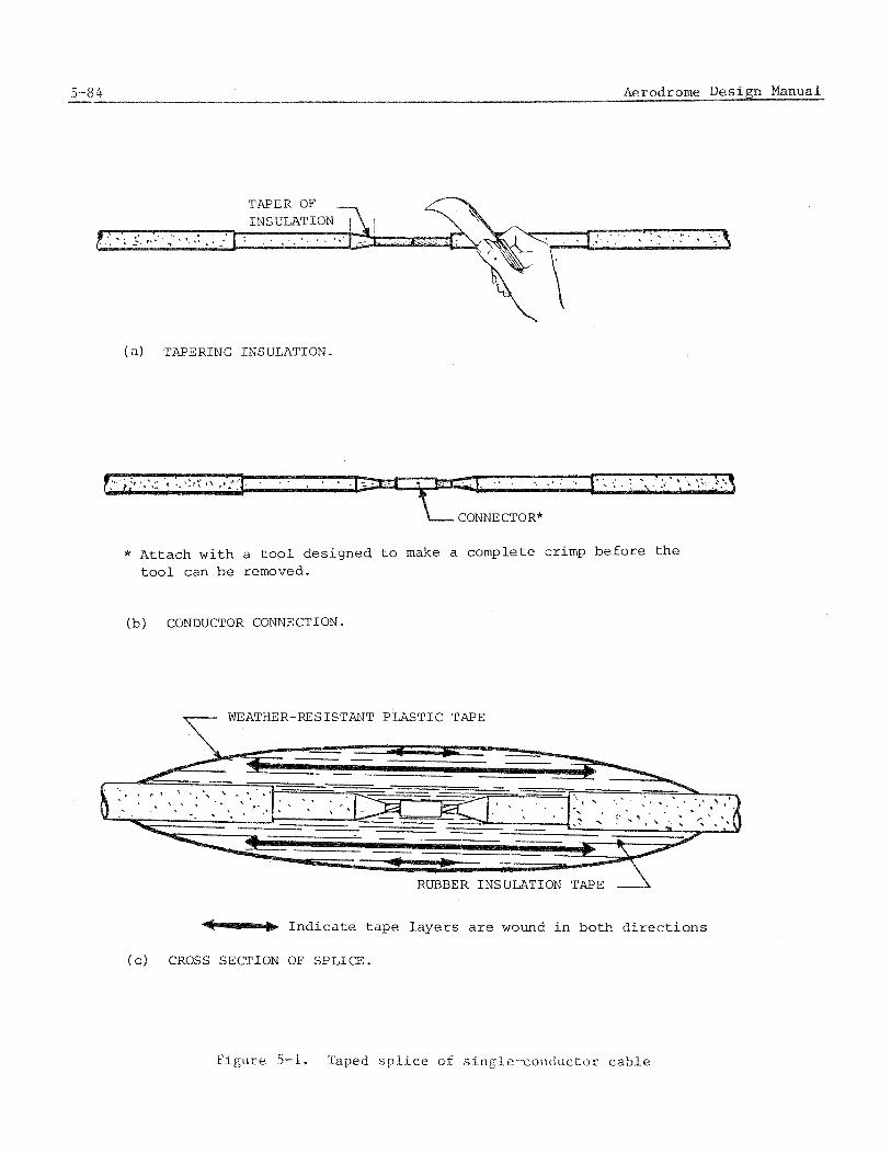
(a) TAPERING INSULATION.
CONNECTOR*
* Attach with a t o o l designed t o make a complete crimp before t h e t o o l can be removed.
(b) CONDUCTOR CONNECTION.
T WEATHER-RESISTANT P L A S T I C TAPE
RUBBER INSULATION TAPE 2
Ind ica t e tape l aye r s are wound i n both d i r e c t i o n s
( c ) CROSS SECTION OF SPLICE.
: r r g u r e 5-i. s p l i c e of s~ .ng ie -conduc to r cable
5.2.2.7 Continue t o wrap t h e rubber t a p e a s i n 5.2.2,5 t o n o t l e s s t h a n 1.5 t imes t h e d iamete r of t h e cab le . C a r e f u l l y apply t e n s i o n on t h e t a p e t o p r e v e n t any voids and o b t a i n good adhes ion t o t h e c a b l e s u r f a c e s and each i n s i d e l a y e r of t a p e .
5.2.2.8 Over t h e rubber t a p e , add s e v e r a l l a y e r s of h igh- insu la t ion- res i s tance , f l ame- re ta rdan t , weather- and c o l d - r e s i s t a n t t a p e . Apply t h e p l a s t i c t a p e w i t h apprec i - a b l e t e n s i o n and over lapp ing each t u r n by approximate ly 5 0 p e r c e n t of i t s wid th . The p l a s t i c t a p e should extend f o r 3 cm o r more a l o n g t h e s u r f a c e of t h e i n s u l a t i o n of s h e a t h on each s i d e of t h e s p l i c e .
5.2.2.9 If t h e c a b l e has a s t e e l - a r m o r o r o t h e r m e t a l l i c c o v e r , connec t a l e n g t h of grounding b r a i d a c r o s s t h e s p l i c e and f a s t e n t o t h e armor on t h e c a b l e w i t h s u i t a b l e clamp connec to r s and /o r s o l d e r on each s i d e of t h e s p i i c e s ( s e e F igure 5-2a). If t h e c a b l e i s l e a d encased, make a s u i t a b l e wiped-lead j o i n t over t h e s p l i c e t o p rov ide a waterproof s e a l t o t h e l e a d cover ing on t h e c a b l e . I f t h e meta l cover ing i s p r o t e c t e d from c o r r o s i o n by a c o a t i n g , apply a c o a t i n g of s i m i l a r m a t e r i a l over t h e e n t i r e s u r f a c e of t h e c a b l e and s p l i c e i n t h e a r e a of t h i s work.
5.2.3.1 Use of connector k i t s . In r e c e n t y e a r s most s e r i e s - c i r c u i t connec t ions have been made u s i n g connector k i t s . Although t h e c o s t of connector k i t s i s s i g n i f i c a n t , t h e t ime saved i n i n s t a l l a t i o n and t h e e a s e w i t h wich c i r c u i t s can be opened and r e c l o s e d when l o c a t i n g f a u l t s have made t h e i r u s e d e s i r a b l e . S ince t h e l e a d s of most i s o l a t i n g t r a n s f o r m e r s a r e now manufactured w i t h connec to r s , c a b l e connec to r s a r e r e q u i r e d and p rov ide an easy means of connec t ing o r d i s c o n n e c t i n g t h e t r a n s f o r m e r i n t o t h e s e r i e s c i r c u i t and t o t h e l i g h t . Single-conductor connec to r s a r e shown i n F i g u r e 5-3.
5.2.3.2 I n s t a l l a t i o n of connec to r s . The c a b l e ends shou ld be p repared c a r e f u l l y i n accordance w i t h t h e i n s t r u c t i o n s , keeping bo th t h e c a b l e ends and t h e connec to r s u r f a c e s f r e e of d i r t and mois tu re , Make c e r t a i n t h a t any c a v i t i e s between. the c a b l e and i n i e t i o r o i t h e connector a r e f i l l e d w i t h t h e g e l provided CO preven t v o i d s . A f t e r j o i n i n g t h e connectors e n s u r e t h a t a i r i s no t t r apped which may t end t o f o r c e t h e con- n e c t i o n a p a r t . Taping over t h e j o i n t w i t h v i n y l e l e c t r i c t a p e t o keep t h e a r e a c l e a n and from s e p a r a t i n g i s suggested.
5.2.4 Coaxia l c a b l e s
5.2.4.1 Non-pressurized c o a x i a l c a b l e s . Coaxia l c a b l e shou ld be j o i n e d u s i n g appro- p r i a t e c o a x i a l connectors . Each connec to r should be covered w i t h a 1 5 cm minimm l e n g t h of h e a t s h r i n k a b l e tub ing hav ing a 3 : 1 o r h i g h e r s h r i n k r a t i o . A s u i t a b l e s p r a y c a b l e adhes ive may be sprayed on t h e c a b l e bu t no t t h e connector p r i o r t o s h r i n k i n g . A flame- l e s s h e a t gun should be used f o r s h r i n k i n g t h e h e a t s h r i n k a b l e tub ing . An a l t e r n a t e cover ing may be p r e s t r e t c h e d , mechanical ly s h r i n k a b l e t u b i n g a p p l i e d as recommended by t h e manufacturer .
5.2.4.2 S p l i c e s i n p r e s s u r i z e d c o a x i a l c a b l e s . No f i e l d - i n s t a l l e d s p l i c e i n p r e s s u r i z e d c o a x i a l c a b l e shou ld be a l lowed u n l e s s s p e c i f i c a l l y a u t h o r i z e d .

I--- VINYL PLASTIC TAPE ANCHOR FOR BRAID
METAL ARMOR
SOLDER FILL ELECTRICAL GROUND BRAID
RUBBER INSULATION TAPE
( a ) CONNECTING ARMOR ACROSS THE S P L I C E
WEATHER-RESISTANT PLASTIC TAPE ( 4 LAYERS-1/2 LAPPED, WITH LIQUID ELECTRICAL COATING APPLIED)
(b) OUTER COVERING OF THE S P L I C E

(a) FACTORY MOLDED PLUG
(b) FACTOR MOLDED RECEPTACLE
PIN -
- _ -
METAL SOCKET
MIN 2 SAW SLOTS
SOCKET
OPTION& INTERN OPTIONAL INTER L O m I NG BESIGH LbCRlNG DESIGN
( c ) F I E L D ATTACHED CONNECTORS
5.2.5 Connection of conductors
5.2.5.1 Power conductors . Connections of c a b l e conductors shou ld be made u s i n g crimp connec to r s u t i l i z i n g a crimping t o o l des igned t o make a complete crimp b e f o r e t h e t o o l can be removed. S p l i t - b o l t connec to r s may be used f o r l o w v o l t a g e c i r c u i t s of 600 v o l t s o r l e s s .
5.2.5.2 Cont ro l and t e l ephone c a b l e s . Jo in ing of t e l ephone o r c o n t r o l conduc to r s should be done w i t h a t w i s t e d and s o l d e r e d s p l i c e o r a n a p p r o p r i a t e s e l f - s t r i p p i n g , p r e i n s u l a t e d connector i n s t a l l e d w i t h t h e s p e c i f i c t o o l des igned t o crimp t h e connector . Color coding of t h e conduc to r s shou ld be fo l lowed throughout t h e i n s t a l l a t i o n .
5.2.5.3 Cable armor and s h i e l d s . Armor s h i e l d s shou ld be e l e c t r i c a l l y bonded a c r o s s t h e s p l i c e by c l e a n i n g and s o l d e r i n g . Use s e c t i o n s of me ta l b r a i d and conduc t ing t a p e , i f needed. Armor and s h i e l d i n g should be complete ly i n s u l a t e d from e a c h and from ground, excep t a s no ted i n paragraph 4.5.3.3.

![62-00 ICAO+Doc+9157 Aerodrome+Design+Manual Part+4+-+Visual+Aids It 110228 Gan[1]](https://static.fdocuments.net/doc/165x107/55cf9bf3550346d033a7fb40/62-00-icaodoc9157-aerodromedesignmanual-part4-visualaids-it-110228.jpg)