AeroD Handbook First Edition
202
1 THE AERODYNAMICS HANDBOOK By THE AERO CLUB BPGC
-
Upload
zenin-easa -
Category
Documents
-
view
86 -
download
0
description
From the students of BITS Pilani, Goa.Aerodynamics Handbook.
Transcript of AeroD Handbook First Edition

1
THE AERODYNAMICS HANDBOOK
By THE AERO CLUB
BPGC

2
Special thanks to the club’s founding members, Harsha Vardhan Sripathi, Siddharth Parmar, the
mechanical pro, Shad Ahmad, the electronics pro, Shatruddha Singh Kushwaha, our entertainer,
Rohan Verma, our perennial source of treats, Kriti Garuda, to the brilliant current core members and
the pro-est of all AeroD members, Sagar Bose.

3
FOREWARD A hearty welcome aboard to all you new aerodynamics enthusiasts .The
Aerodynamics club of BITS Pilani Goa Campus warmly welcomes you to its crazy and
creative midst.
Aerodynamics literally means the following - the movement of air. It’s almost
comical how many aerodynamic phenomena we take for granted on a day to day basis –
what happens when we blow over a paper? What happens when we drop a feather? How
do large heavy things manage to keep up in the sky without dropping right down? The
answer is aerodynamics.
Here in the Aero Club of BPGC, we deal with such phenomenon on a day to day
basis. We are inspired by the daily incidences and implications of air. As a group of
individuals who are deeply interested in the fields of aerodynamics and aeronautical
engineering, we strive to extend our reach into all of the aspects of these fields. Fortunately
for us, the most accessible and readily available expression of our interest is RC flying.
Yes, every member of Aero BPGC is skilled in the various aspects of design,
construction and piloting radio controlled aircraft. And given the number of people in the
club, their collective knowledge is a vast sea of jugaad. RC flying is a hobby that involves a
large number of fields and a larger number of things to keep in mind while carrying out
these tasks. It will surely keep your mind active and interested for a very long while.
So why write a handbook in the first place?
Ultimately, we at Aero BPGC realized that there are simply too many things for one
person to remember and keep in mind while building and flying RC aircraft. Imbibing this
knowledge into one’s mind is a job that takes a lot of time and patience and not too many
people can get it in their first six months of aero modeling.
To simplify and aid the process of learning about aerodynamics and RC flying, we
decided to put down our collective knowledge in a book. Yes, a handbook of sorts that will
be a quick reference guide in some cases, a textbook in other cases. But all in all, a tome of
our knowledge and experience that we hope to pass onto future generations of aero
modellers. Always remember that knowledge and learning are never complete and the
same holds good for this book also. We hope that future generations of the club will
constantly keep updating the knowledge in this book with their experience.
Another paragraph must be taken aside to thank all the members of the Aero club
for their knowledge and advice in the creation of this handbook. The book was a joint
venture of past and present members of the club. It is an amalgamation of the skills and
experiences of every single member.
4
To take another paragraph, it’s important that we, Aero BPGC, take a moment to
enlighten the readers of these almost religious lines by which we work.
“Where the clear blue sky is the only classroom that matters, where the gentle breeze from the ocean is the most respected teacher, where exams and problem statements are set by Mother Nature herself, and where the results are measured not in marks or grades but in self-satisfaction. There lies the true Aerodynamics Club.”
-Harsha Vardhan Sripathi
We sincerely hope that this book aids you in your quest!
- Aero BPGC

5
Disclaimer
A disclaimer? For a book? Isn’t that unnecessary? However, because of the levels of risk, the cost
of equipment and the rules and regulations involved, we must resort to writing a precautionary
disclaimer ahead of the entire book. That doesn’t mean that you have to feel paranoid about the
club’s knowledge.
1. The entire manual has been written based off the practical knowledge of the members of
the aerodynamics club. It is a basic set of instructions for flying and building planes. It also
contains several textbook-like sections about aerodynamics.
However, one must accept the possibility that there we are a growing club and hence, we
have not experienced all possible situations and learnt all the possible lessons from these.
Hence, in case an unknown situation comes up, the user is expected to react with the
lessons learnt from the handbook, his or her own experience and his or her COMMON
SENSE.
In case such situations go awry, do not blame the handbook.
2. The book is NOT complete yet. It is NEVER complete and will be constantly expanding and
hence, is subject to constant change. That’s the best part.

6
INDEX
Chapter………………………………………………………………………………………………………….…………Page No.
INTRODUCTION ............................................................................................................................................... 9
1.1) THE HISTORY OF FLIGHT ...................................................................................................................... 10
1.2) HISTORY OF AERO BPGC ...................................................................................................................... 18
AERODYNAMICS ............................................................................................................................................ 20
2.1) BASICS OF AERODYNAMICS ................................................................................................................. 21
2.2) THEORIES OF FLIGHT ........................................................................................................................... 22
2.3) THE COANDA EFFECT ........................................................................................................................... 23
2.4) AIRFOILS AND ANGLE OF ATTACK ........................................................................................................ 26
2.5) STALL ................................................................................................................................................... 27
2.6) POWER AND DRAG .............................................................................................................................. 29
2.7) BASIC FLIGHT ....................................................................................................................................... 36
ELEMENTS OF RC FLYING ............................................................................................................................... 38
3.1) INTRODUCTION ................................................................................................................................... 38
3.2) THEORY ............................................................................................................................................... 39
3.3) PLANNING, DECIDING ON A DESIGN .................................................................................................... 39
3.4) BUILDING ............................................................................................................................................. 39
3.5) FLYING ................................................................................................................................................. 40
3.6) WINDING UP ........................................................................................................................................ 40
TYPES OF PLANES ........................................................................................................................................... 42
4.1) INTRODUCTION ................................................................................................................................... 43
4.2) GLIDERS AND SAILPLANES ................................................................................................................... 44
4.3) SCALE MODEL PLANES ......................................................................................................................... 45
4.4) TRAINERS ............................................................................................................................................. 46
4.5) 3D FLYERS ............................................................................................................................................ 48
4.6) JET AIRCRAFT ....................................................................................................................................... 49
4.7) PYLON RACERS .................................................................................................................................... 50
VTOL AIRCRAFT .............................................................................................................................................. 51
5.1) INTRODUCTION ................................................................................................................................... 52
5.2) HELICOPTERS ....................................................................................................................................... 53
5.3) TRICOPTERS ......................................................................................................................................... 61
5.4) FLYING A VTOL AIRCRAFT .................................................................................................................... 63
PARTS OF A PLANE ......................................................................................................................................... 68
6.1) INTRODUCTION ................................................................................................................................... 69
6.2) THE FUSELAGE ..................................................................................................................................... 70
6.3) WINGS ................................................................................................................................................. 71
6.4) AILERONS ............................................................................................................................................ 75
6.5) THE TAIL SECTION ................................................................................................................................ 78

7
6.6) FLAPS AND SLATS................................................................................................................................. 82
6.7) LANDING GEAR/ UNDERCARRIAGE...................................................................................................... 85
POWER SYSTEMS ........................................................................................................................................... 88
7.1) INTRODUCTION ................................................................................................................................... 89
7.2) THE PHYSICS OF EFFICIENCY ................................................................................................................ 90
7.3) THE DIFFERENCE BETWEEN POWER AND THRUST .............................................................................. 90
7.4) THE DIFFERENT TYPES OF POWER PLANTS .......................................................................................... 93
7.4.1) TURBOPROP ....................................................................................................................................... 93
7.4.2) MOTORJET ......................................................................................................................................... 94
7.4.3) THE JET ENGINE or THE TURBO JET ................................................................................................... 95
7.4.4) PULSE JET ........................................................................................................................................... 96
7.4.5) THE RAMJET ....................................................................................................................................... 96
7.4.6) SCRAMJETS ........................................................................................................................................ 97
7.4.7) TURBOSHAFT ..................................................................................................................................... 98
7.4.8) TURBOFAN ......................................................................................................................................... 99
7.4.9) INTERNAL COMBUSTION ENGINE .................................................................................................... 100
7.4.10) GLOW ENGINES .............................................................................................................................. 100
7.5) SUMMARY OF AIR BREATHING ENGINES ........................................................................................... 105
7.6) PROPELLERS ...................................................................................................................................... 105
7.7) STYLES OF PROPELLERS ..................................................................................................................... 107
7.8) 3 & 4 BLADED CONVERSION CHART ................................................................................................... 108
7.9) BALANCING A PROPELLER ................................................................................................................. 109
7.10) PHENOMENON ASSOCIATED WITH PROPELLERS .............................................................................. 110
7.11) CONCLUSION ..................................................................................................................................... 112
AVIONICS ..................................................................................................................................................... 113
8.1) INTRODUCTION ................................................................................................................................. 114
8.2) BATTERY PACKS ................................................................................................................................. 115
8.3) MOTORS ............................................................................................................................................ 120
8.4) ELECTRONIC SPEED CONTROLLERS (ESC)........................................................................................... 123
8.5) SERVOS .............................................................................................................................................. 127
8.6) GYROSCOPES ..................................................................................................................................... 129
8.7) CONCLUSION - PUTTING IT ALL TOGETHER ....................................................................................... 132
MATERIALS AND TOOLS ............................................................................................................................... 134
9.1) INTRODUCTION ................................................................................................................................. 135
9.2) MATERIALS ........................................................................................................................................ 136
9.2.1) Balsa Wood ...................................................................................................................................... 136
9.2.2) Coroplast Sheet ................................................................................................................................ 138
9.2.3) Depron ............................................................................................................................................. 139
9.2.4) Styrofoam ........................................................................................................................................ 141
9.3) TOOLS REQUIRED .............................................................................................................................. 143
9.3.1) Blade ................................................................................................................................................ 143
9.3.2) Hack Saw .......................................................................................................................................... 143
9.3.3) Foam Cutter ..................................................................................................................................... 144
9.3.4) Drill machine .................................................................................................................................... 145
9.2.6) Soldering Iron ................................................................................................................................... 146
9.2.6) Screw Driver ..................................................................................................................................... 147
9.2.7) Hammer ........................................................................................................................................... 147

8
9.2.8) Sand Paper ....................................................................................................................................... 148
9.4) ADHESIVES ........................................................................................................................................ 149
9.4.1) CA Glue ............................................................................................................................................ 149
9.4.2) Epoxy glue ........................................................................................................................................ 150
9.4.3) Hot melt adhesive (HMA) ................................................................................................................. 151
9.4.4) Resins ............................................................................................................................................... 152
YOU’RE RC ................................................................................................................................................... 153
10.1) INTRODUCTION ................................................................................................................................. 154
10.2) CLASSIFICATION OF RC’S ................................................................................................................... 155
10.3) HOW TO HOLD AND USE AN RC ......................................................................................................... 156
10.4) RC STICK MODES ................................................................................................................................ 158
10.5) RECEIVER AND PAIRING ..................................................................................................................... 160
10.6) RC MENUS AND OPTIONS .................................................................................................................. 162
10.7) CONCLUSION ........................................................................................... ERROR! BOOKMARK NOT DEFINED.
FLIGHT ......................................................................................................................................................... 167
11.1) FLYING – A GUIDE FROM TAKE OFF TO LANDING .............................................................................. 168
11.2) POINTS TO REMEMBER WHILE FLYING .............................................................................................. 168
11.3) PRE-FLIGHT CHECKLIST ...................................................................................................................... 169
11.4) START-UP PROCEDURES .................................................................................................................... 172
11.5) TAKE-OFF ........................................................................................................................................... 174
11.6) CLIMBING .......................................................................................................................................... 176
11.7) TURNING ........................................................................................................................................... 177
11.8) LANDING ........................................................................................................................................... 178
11.9) SHUT-DOWN PROCEDURE ................................................................................................................. 182
11.10) EMERGENCY PROCEDURES ........................................................................................................... 183
11.11) CRASH ........................................................................................................................................... 189
11.12) CONCLUSION ................................................................................................................................ 190
A CASE STUDY OF THE IL’ NOSTRO ............................................................................................................... 191
12.1) INTRODUCTION ................................................................................................................................. 192
12.2) DESIGNING AND BRAINSTORMING ................................................................................................... 193
12.3) MATERIALS AND TOOLS REQUIRED ................................................................................................... 194
12.4) CALCULATING ELECTRONICS ............................................................................................................. 195
12.5) PUTTING IT ALL TOGETHER ................................................................................................................ 195
12.6) MAIDEN TEST FLIGHT ........................................................................................................................ 196
CONCLUDING THE HANDBOOK………………………………………………………………………………………………………………….193

9
CHAPTER 1 INTRODUCTION
10
1.1) THE HISTORY OF FLIGHT
Mankind was always awed by aviation. The history of flight goes beyond two millennia from
the earliest attempts in kites and gliders to powered heavier-than-air, supersonic and hypersonic
flight. For many centuries, humans have tried to fly like birds. Around 200 B.C. the Chinese made the
kite, which was the first man-made object that could fly. Kites have been important to the invention
of flight as they were the forerunner to balloons and gliders. Wings made of feathers or light weight
wood, have been attached to arms to test their ability to fly. The results were often disastrous as the
muscles of the human arms are not like birds and cannot move with the strength of a bird.
EARLY ATTEMPTS
The ancient Greek engineer, Hero of Alexandria, worked with air pressure and steam to
create sources of power. One experiment that he developed was the aeolipile which used jets of
steam to create rotary motion. Around 400 BC, Archytas, the Greek philosopher, mathematician,
astronomer, statesman and strategist, designed and built a bird-shaped, apparently steam powered
model named "The Pigeon", which is said to have flown some 200 meters.
The Kongming lantern (proto hot air balloon) was used in China in ancient times to scare the
enemy troops. An oil lamp was installed under a large paper bag, and the bag floated in the air due
to the lamp heating the air. Hot-air balloons in China were known from the 3rd century BC. In the
5th century B.C. Lu Ban invented a 'wooden bird' which may have been a large kite, or which may
have been an early glider. In 1st century AD, when Wang Mang tried to recruit specialist as scout to
Xiong Nu, a man binding himself with bird feather glided about 100 meters, but finally landed. 559,
Yuan Huangtou, Ye, first manned kite glide to take off from a tower.
In the 9th century, at the age of 65, the Muslim Andalusian polymath Abbas Ibn Firnas is said
to have flown from the hill Jabal al-'arus by employing a rudimentary glider. While "alighting again
on the place whence he had started," he eventually crashed and sustained injury which some
contemporary critics attributed to a lack of tail. Between 1000 and 1010, the English Benedictine
monk Eilmer of Malmesbury flew for about 200 meters using a glider (c. 1010), but he too sustained
injuries.
Leonardo da Vinci made the first real studies of flight in the 1480's. He had over 100
drawings that illustrated his theories on flight. The Ornithopter flying machine was never actually
created. It was a design that Leonardo da Vinci created to show how man could fly. The modern day
helicopter is based on this concept. Based on his drawings, and using materials that would have
been available to him, a prototype constructed in the late 20th century was shown to fly. However,
his sketchy design was interpreted with modern knowledge of aerodynamic principles, and whether
his actual ideas would have flown is not known. A model he built for a test flight in 1496 did not fly,
and some other designs, such as the four-person screw-type helicopter, have severe flaws.
11
Italian inventor, Tito Livio Burattini, invited by the Polish King Władysław IV to his court in
Warsaw, built a model aircraft with four fixed glider wings in 1647. Described as "four pairs of wings
attached to an elaborate 'dragon'", it was said to have successfully lifted a cat in 1648 but not
Burattini himself. His "Dragon Volant" is considered "the most elaborate and sophisticated
aeroplane to be built before the 19th Century".
MODERN FLIGHT
The brothers, Joseph Michel and Jacques Etienne Montgolfier, were inventors of the first hot
air balloon. They used the smoke from a fire to blow hot air into a silk bag. The silk bag was attached
to a basket. The hot air then rose and allowed the balloon to be lighter-than-air. In 1783, the first
passengers in the colorful balloon were a sheep, rooster and duck. It climbed to a height of about
6,000 feet and traveled more than 1 mile. After this first success, the brothers began to send men up
in balloons. The first manned flight was on November 21, 1783, the passengers were Jean-Francois
Pilatre de Rozier and Francois Laurent. Ballooning became a major "rage" in Europe in the late 18th
century, providing the first detailed understanding of the relationship between altitude and the
atmosphere.
Work on developing a steerable (or dirigible) balloon (now called an airship) continued
sporadically throughout the 19th century. The first powered, controlled, sustained lighter-than-air
flight is believed to have taken place in 1852 when Henri Giffard flew 24 km in France, with a steam
engine driven craft. Non-steerable balloons were employed during the American Civil War by the
Union Army Balloon Corps. Another advance was made in 1884, when the first fully controllable
free-flight was made in a French Army electric-powered airship, La France, by Charles Renard and
Arthur Krebs. The 52 m long, 1,900 m3 airship covered 8 km in 23 minutes with the aid of an 8½
horsepower electric motor. However, these aircraft were generally short-lived and extremely frail.
Routine, controlled flights would not occur until the advent of the internal combustion engine.
Although airships were used in both World War I and II, and continue on a limited basis to this day,
their development has been largely overshadowed by heavier-than-air craft.
The first published paper on aviation was "Sketch of a Machine for Flying in the Air" by
Emanuel Swedenborg published in 1716. This flying machine consisted of a light frame covered with
strong canvas and provided with two large oars or wings moving on a horizontal axis, arranged so
that the upstroke met with no resistance while the down stroke provided lifting power. Swedenborg
knew that the machine would not fly, but suggested it as a start and was confident that the problem
would be solved.
Francis Herbert Wenham built a series of unsuccessful unmanned gliders. He found that the
most of the lift from a bird-like wing appeared to be generated at the front edge, and concluded
correctly that long, thin wings would be better than the bat-like ones suggested by many, because
they would have more leading edge for their weight. Today this measure is known as aspect ratio.
He presented a paper on his work to the newly formed Aeronautical Society of Great Britain in 1866,
and decided to prove it by building the world's first wind tunnel in 1871. Members of the Society
used the tunnel and learned that cambered wings generated considerably more lift than expected by

12
Cayley's Newtonian reasoning, with lift-to-drag ratios of about 5:1 at 15 degrees. This clearly
demonstrated the ability to build practical heavier-than-air flying machines; what remained was the
problem of controlling and powering the flight.
In 1871 the Frenchman Alphonse Pénaud successfully flew a model aircraft powered by
twisted rubber in Paris. This was significant because the model had two features which gave it a
degree of inherent stability: the rear-mounted taiplane was set at a smaller angle of incidence than
the wings, and the wings were curved up at the tips, giving them dihedral. The principle of a
difference in angle of incidence between the lifting surface and a stabilising tailplane was an original
and important contribution to the theory of aeronautics. The use of dihedral had been worked out
by Cayley, although at the time Cayleys work was largely unknown, and Pénaud had arrived at the
idea independently. Rubber powered model aircraft inspired a whole generation of future flight
pioneers, including the Wright brothers who were given them as toys when children.
German engineer, Otto Lilienthal, studied aerodynamics and worked to design a glider that
would fly in 1891. He was the first person to design a glider that could fly a person and was able to
fly long distances. He was fascinated by the idea of flight. Based on his studies of birds and how they
fly, he wrote a book on aerodynamics that was published in 1889 and this text was used by the
Wright Brothers as the basis for their designs. After more than 2500 flights, he was killed when he
lost control because of a sudden strong wind and crashed into the ground. Picking up where
Lilienthal left off, Octave Chanute took up aircraft design after an early retirement, and funded the
development of several gliders. In the summer of 1896 his team flew several of their designs many
times at Miller Beach, Indiana, eventually deciding that the best was a biplane design that looks
surprisingly modern. Like Lilienthal, he heavily documented his work while photographing it, and
was busy corresponding with like-minded hobbyists around the world. Chanute was particularly
interested in solving the problem of aerodynamic instability of the aircraft in flight, which birds
compensate for by instant corrections, but which humans would have to address either with
stabilizing and control surfaces or by moving the center of gravity of the aircraft, as Lilienthal did.
The most disconcerting problem was longitudinal instability (divergence), because as the angle of
attack of a wing increased, the center of pressure moved forward and made the angle increase
more. Without immediate correction, the craft would pitch up and stall. Much more difficult to
understand was the mixing of lateral/directional stability and control.
PIONEER ERA
Blimps were the first aircrafts to have made routine controlled flights. These blimps were
non-rigid aircrafts. The most successful early pioneering pilot of this type of aircraft was the Brazilian
Alberto Santos-Dumont who effectively combined a balloon with an internal combustion engine. At
the same time that non-rigid airships were starting to have some success, rigid airships were also
becoming more advanced. Indeed, rigid body dirigibles would be far more capable than fixed-wing
aircraft in terms of pure cargo carrying capacity for decades. Dirigible design and advancement was
brought about by the German count, Ferdinand von Zeppelin. Construction of the first Zeppelin
airship began in 1899 in a floating assembly hall on Lake Constance in the Bay of Manzell,
Friedrichshafen. This was intended to ease the starting procedure, as the hall could easily be aligned

13
with the wind. The prototype airship LZ 1 (LZ for "Luftschiff Zeppelin") had a length of 128 m, was
driven by two 10.6 kW Daimler engines and balanced by moving a weight between its two nacelles.
In 1902 Spanish engineer Leonardo Torres Quevedo developed his own zeppelin airship, with which
he solved the serious balance problems the earlier Zeppelins had shown in previous flight attempts.
In 1877, Enrico Forlanini developed an unmanned helicopter powered by a steam engine. It
rose to a height of 13 meters, where it remained for some 20 seconds, after a vertical take-off from
a park in Milan. The first successful rotorcraft of any type, however, wasn't a true helicopter, but an
autogyro invented by Spanish engineer Juan de la Cierva in 1919. These kind of rotorcraft were
mainly used until the development of modern helicopters, when, for some reason, they became
largely neglected, although the idea has since been resurrected several times. Since the first
practical helicopter was the Focke Achgelis Fw 61 (Germany, 1936), the autogyro's golden age only
lasted around 20 years.
WRIGHT BROTHERS
Orville and Wilbur Wright were very deliberate in their quest for flight. First, they spent
many years learning about all the early developments of flight. They completed detailed research of
what other early inventors had done. They read all the literature that was published up to that time.
Then, they began to test the early theories with balloons and kites. They learned about how the
wind would help with the flight and how it could affect the surfaces once up in the air. The next step
was to test the shapes of gliders much like George Cayley did when he was testing the many
different shapes that would fly. They spent much time testing and learning about how gliders could
be controlled. They designed and used a wind tunnel to test the shapes of the wings and the tails of
the gliders. After they found a glider shape that consistently would fly in the tests in the North
Carolina Outer Banks dunes, then they turned their attention to how to create a propulsion system
that would create the lift needed to fly. The early engine that they used generated almost 12
horsepower.
The Wrights appear to be the first design team to make serious studied attempts to
simultaneously solve the power and control problems. They solved the control problem by inventing
wing warping for roll control, combined with simultaneous yaw control with a steerable rear rudder.
Almost as an afterthought, they designed and built a low-powered internal combustion engine.
Relying on their wind tunnel data, they also designed and carved wooden propellers that were more
efficient than any before, enabling them to gain adequate performance from their marginal engine
power. Although wing-warping was used only briefly during the history of aviation, when used with a
rudder it proved to be a key advance in order to control an aircraft. While many aviation pioneers
appeared to leave safety largely to chance, the Wrights' design was greatly influenced by the need to
fly without unreasonable risk to life and limb, by surviving crashes. This emphasis, as well as
marginal engine power, was the reason for low flying speed and for taking off in a head wind.
Performance (rather than safety) was also the reason for the rear-heavy design, because the canard
could not be highly loaded; anhedral wings were less affected by crosswinds and were consistent
with the low yaw stability.

14
The "Flyer" lifted from level ground to the north of Big Kill Devil Hill on December 17, 1903.
Orville piloted the plane which weighed six hundred and five pounds. The first heavier-than-air flight
traveled one hundred twenty feet in twelve seconds. The two brothers took turns during the test
flights. It was Orville's turn to test the plane, so he is the brother that is credited with the first flight.
Subsequently they made Flyers II and III making modifications and improvements to the previous
model.
WORLD WAR I
Many planes right after invention were used for military purposes. Italy was the first country
to actually deploy planes which made reconnaissance, bombing and shelling correction military
flights during the Italian-Turkish war (1911-12) in Libya. This was followed by Bulgaria when they
used planes for bombing during the First Balkan War (1912-13). The first war to see major use of
planes in offensive, defensive and reconnaissance capabilities was World War I. The Allies and
Central Powers both used planes extensively.
It was not long before aircraft were shooting at each other, but the lack of any sort of steady
point for the gun was a problem. The French solved this problem when, in late 1914, Roland Garros
attached a fixed machine gun to the front of his plane, but while Adolphe Pegoud would become
known as the first "ace", getting credit for five victories, before also becoming the first ace to die in
action, it was German Luftstreitkräfte Leutnant Kurt Wintgens, who, on July 1, 1915, scored the very
first aerial victory by a purpose-built fighter plane, with a synchronized machine gun. Aviators were
styled as modern day knights, doing individual combat with their enemies. Several pilots became
famous for their air to air combats; the most well-known is Manfred von Richthofen, better known
as the Red Baron, who shot down 80 planes in air to air combat with several different planes, the
most celebrated of which was the Fokker Dr.I. On the Allied side, René Paul Fonck is credited with
the most all-time victories at 75, even when later wars are considered. France, Britain, Germany and
Italy were the leading manufacturers of fighter planes that saw action during the war.
WORLD WAR II
Aeroplanes evolved from low-powered biplanes made from wood and fabric to sleek, high-
powered monoplanes made of aluminum, based primarily on the founding work of Hugo Junkers
during the World War I period. The age of the great airships came and went. Air shows became
famous after World War I, many pilots known as “barnstormers” tried their hands at many
competitions to show off their skills. The air races drove engine and airframe development—the
Schneider Trophy, for example, led to a series of ever faster and sleeker monoplane designs
culminating in the Supermarine S.6B. With pilots competing for cash prizes, there was an incentive
to go faster. Amelia Earhart was perhaps the most famous of those on the barnstorming/air show
circuit. She was also the first female pilot to achieve records such as crossing of the Atlantic and
Pacific Oceans. Australian Charles Kingsford Smith was the first to fly across the larger Pacific Ocean

15
in the Southern Cross. His crew left Oakland, California to make the first trans-Pacific flight to
Australia in three stages – Oakland to Hawaii, Suva and Brisbane. With Ulm, Kingsford Smith later
continued his journey being the first in 1929 to circumnavigate the world, crossing the equator
twice. By 1929, airship technology had advanced to the point that the first round-the-world flight
was completed by the Graf Zeppelin in September and in October; the same aircraft inaugurated the
first commercial transatlantic service. However the age of the dirigible ended following the
destruction by fire of the zeppelin Hindenburg just before landing at Lakehurst, New Jersey on May
6, 1937, killing 35 of the 97 people aboard.
World War II saw a drastic increase in the pace of aircraft development and production. All
countries involved in the war stepped up development and production of aircraft and flight based
weapon delivery systems, such as the first long range bomber. More flexible aircraft were developed
and weapons allowed precise attacks on small targets with dive bombers, fighter-bombers, and
ground-attack aircraft. New technologies like radar also allowed more coordinated and controlled
deployment of air defense.
The first functional jetplane was the Heinkel He 178 (Germany), flown by Erich Warsitz in
1939, followed by the world's first operational jet aircraft, the ME 262, in July 1942 and world's first
jet-powered bomber, the Arado AR 234, in June 1943. British developments, like the Gloster Meteor,
followed afterwards, but saw only brief use in World War II. The first cruise missile (V-1), the first
ballistic missile (V-2), the first (and to date only) operational rocket-powered combat aircraft Me 163
and the first vertical take-off manned point-defense interceptor Bachem Ba 349 were also
developed by Germany. However, jet fighters had only limited impact due to their late introduction,
fuel shortages, the lack of experienced pilots and the declining war industry of Germany.
Not only airplanes, but also helicopters saw rapid development in the Second World War.
With the introduction of the Focke Achgelis Fa 223, the Flettner Fl 282 in 1941 in Germany and the
Sikorsky R-4 in 1942 in the USA, for the first time larger helicopter formations were produced and
deployed.
COLD WAR
After World War II, commercial aviation grew rapidly, using mostly ex-military aircraft to
transport people and cargo. This growth was accelerated by the glut of heavy and super-heavy
bomber airframes like the B-29 and Lancaster that could be converted into commercial aircraft.
The DC-3 also made for easier and longer commercial flights. The first commercial jet airliner
to fly was the British de Havilland Comet. USSR's Aeroflot became the first airline in the world to
operate sustained regular jet services on September 15, 1956 with the Tupolev Tu-104. The Boeing
707, which established new levels of comfort, safety and passenger expectations, ushered in the age
of mass commercial air travel
In October 1947 Chuck Yeager took the rocket-powered Bell X-1 through the sound barrier.
Further barriers of distance fell in 1948 and 1952 with the first jet crossing of the Atlantic and the
first nonstop flight to Australia.

16
The 1945 invention of nuclear bombs briefly increased the strategic importance of military
aircraft in the Cold War between East and West. Even a moderate fleet of long-range bombers could
deliver a deadly blow to the enemy, so great efforts were made to develop countermeasures. At
first, the supersonic interceptor aircraft were produced in considerable numbers. By 1955 most
development efforts shifted to guided surface-to-air missiles. However, the approach changed when
a new type of nuclear-carrying platform appeared that could not be stopped in any feasible way:
intercontinental ballistic missiles. The possibility of these was demonstrated in 1957 with the launch
of Sputnik 1 by the Soviet Union.
In 1961, the sky was no longer the limit for manned flight, as Yuri Gagarin orbited once
around the planet within 108 minutes, and then used the descent module of Vostok I to safely
reenter the atmosphere and reduce speed from Mach 25 using friction and converting velocity into
heat. The United States responded by launching Alan Shepard into space on a suborbital flight in a
Mercury space capsule. With the launch of the Alouette I in 1963, Canada became the third country
to send a satellite in space. The space race between the United States and the Soviet Union would
ultimately lead to the landing of men on the moon in 1969.
In 1967, the X-15 set the air speed record for an aircraft at 4,534 mph (7,297 km/h) or Mach
6.1 (7,297 km/h). Aside from vehicles designed to fly in outer space, this record was renewed by X-
43 in the 21st century.
The Harrier Jump Jet, often referred to as just "Harrier" or "the Jump Jet", is a British
designed military jet aircraft capable of Vertical/Short Takeoff and Landing (V/STOL) via thrust
vectoring. It first flew in 1969. The same year that Neil Armstrong and Buzz Aldrin set foot on the
moon, and Boeing unveiled the Boeing 747 and the Aérospatiale-BAC Concorde supersonic
passenger airliner had its maiden flight. The Boeing 747 was the largest commercial passenger
aircraft ever to fly, and still carries millions of passengers each year, though it has been superseded
by the Airbus A380, which is capable of carrying up to 853 passengers. In 1975 Aeroflot started
regular service on the Tu-144—the first supersonic passenger plane. In 1976 British Airways and Air
France began supersonic service across the Atlantic, with Concorde. A few years earlier the SR-71
Blackbird had set the record for crossing the Atlantic in under 2 hours, and Concorde followed in its
footsteps.
The last quarter of the 20th century saw a slowing of the pace of advancement. No longer
was revolutionary progress made in flight speeds, distances and technology. This part of the century
saw the steady improvement of flight avionics, and a few minor milestones in flight progress.
For example, in 1979 the Gossamer Albatross became the first human powered aircraft to
cross the English Channel. This achievement finally saw the realization of centuries of dreams of
human flight. In 1981, the Space Shuttle made its first orbital flight, proving that a large rocket ship
can take off into space, provide a pressurized life support system for several days, reenter the
atmosphere at orbital speed, precision glide to a runway and land like a plane.
In 1986 Dick Rutan and Jeana Yeager flew an aircraft, the Rutan Voyager, around the world
unrefueled, and without landing. In 1999 Bertrand Piccard became the first person to circle the earth
in a balloon. Focus was turning to the ultimate conquest of space and flight at faster than the speed
of sound.
17
21st Century
Commercial Aviation saw the end of an era with the Concorde getting de-commissioned. It
has developed beyond the imagination of the fathers of aviation. We all know how much
commercial aviation has developed, we can go anywhere in the world by just hopping on a plane.
Flight and aviation are like never before, we see more and more aircrafts breaking old and setting
new records. We have development in all sizes, from tiny MAV drones to the gigantic airbus Beluga.
Not to mention advancement in space travel and satellites.
In the beginning of the 21st century, subsonic military aviation focused on eliminating the
pilot in favor of remotely operated or completely autonomous vehicles. Several unmanned aerial
vehicles or UAVs have been developed. In April 2001 the unmanned aircraft Global Hawk flew from
Edwards AFB in the US to Australia non-stop and unrefuelled. This is the longest point-to-point flight
ever undertaken by an unmanned aircraft, and took 23 hours and 23 minutes. In October 2003 the
first totally autonomous flight across the Atlantic by a computer-controlled model aircraft occurred.
Aviation has reached a whole new level with the plethora of aircrafts and spaceships present
around the world nowadays. Man has shown that there is no boundary that he cannot breach. With
the rapid advancement in technology, maybe it’s not far when we all shift to hover-cars or the
space-cars that we all have seen in “The Jetsons” and not to mention daily spaceships to the Moon,
Mars or perhaps the neighboring galaxy.
18
1.2) HISTORY OF AERO BPGC
The Aerodynamics Club BPGC was founded in the year 2008 by Harsha Vardhan Sripathi of
2006 batch. The coordinators to follow were Atul Telang, Siddharth Parmar, Kriti Garuda and now
Sagar Bose. Sagar has been the best flyer and Harsha by far has the best knowledge about
aerodynamics and flight and has laid down the foundation for the club to soar to great heights. The
club had started off as a group of very enthusiastic people who had a dream to make flying objects
and to actually fly them. The passion and dream has carried on and has been the main driving force
in making the club reach the level it is today. The main aim of all the past Aero club members is to
someday see the club to be the best in India and also participate in high level projects collaborating
with the big guns in Aero such as Boeing, Lockheed etc.
Since Harsha founded it in 2008, the successors have done their best to educate the juniors
and transfer the knowledge that they have obtained and tried their hands at more planes and bigger
and varied projects. Inductions are held every year to recruit new members into the club. We have
always maintained that we are not in search for anyone with technical knowledge but instead we
want passionate people who seriously and whole heartedly want to work. The club had collaborated
with one of India’s best aero-modellers Ansari Wasi and held air-shows and three workshops - Balsa
Glider, SPAD and Tricopter in the first three years of the club. The Balsa Glider that was built in the
workshop was designed by Harsha and Wasi together in the year the club was founded. A balsa scale
model of a P 51 Mustang was also built and flown among many other things. A Coanda effect VTOL
construction was also started. From this year on, the club started conducting an aero event in Quark.
We had the honour of presenting the Mustang and VTOL when APJ Abdul Kallam and K.M. Birla
visited our campus.
The club has definitely grown over the years and we hope that it’s going to keep growing
and reach new levels. The club has become not just a group of random people from different
batches; but a group of friends who are passionate about flying different model aircrafts and are
dedicated to our work. It’s not just about building planes and flying them, it’s the entire process.
We first start with brainstorming and then procuring materials; only then we start the
project and it is like a journey where we have to drive ahead, overcoming different kinds of obstacles
and finally reaching the destination where, we finally have the finished product ready to fly. Testing
the flight capabilities is another challenge altogether. The pilot needs to be vigilant and alert to test
the model properly and check all aspects. After that comes, the rest of the club getting a shot at
flying. But then due to turbulence, pilot defaulting or technical glitches, some of the models end up
crashing. That leads to repairing the broken model.
We pride ourselves in “jugaad”, as we really over stretch the lifetime of every model and fly
it till it can no-more take-off or is crashed to bits. Or sometimes we improve upon the existing model
to make our own improvisations and improvements.
Sometime in the future, the club’s larger aim is to collaborate with international engineer
organizations and become a world renowned authority on hobby aircraft flying. Some of our more
particular goals are to build a manned aircraft and to bring about a B.E. Aerospace degree in the BITS
Pilani course options.

19
Every person has their own interests, some like to build, some like to fly, some like to plan,
some only like to research the theoretical aspects. Depending on your likes, we will guide you and
try to help you as much as we can. Most of the knowledge passes down on a person-to-person basis,
so if you have any doubts just feel free to ask. So strap on your seatbelts and get ready for take-off;
it is going to be a bumpy ride!
GET HIGH LEGALLY!!

20
CHAPTER 2
AERODYNAMICS
21
2.1) BASICS OF AERODYNAMICS
Firstly, A hearty welcome to the world of aerodynamics! There is no phenomenon that
matches up to the fascinating nature of flight. Since the dawn of time, man has strived to mimic
birds and bats and take to the skies. Repeated successes have been made through history but it was
never really understood why those successes were successes.
Firstly, aerodynamics literally means – “The movement of air”. It is a subject that studies
how air moves around objects and obstacles. Air is all around us and hence, it is almost necessary
that we know of its nature.
The following chapter will go on to tell you about the various proposed theories of flight and
how half of them turn out to be false in the end. After introducing the basic theories of flight, it will
go on to speak about how planes fly, how helicopters fly, how planes stabilize themselves and how,
in general, air works around flying objects.
Have a nice reading!

22
2.2) THEORIES OF FLIGHT
Several scientists have tried to explain flight in terms of pressure changes and velocity
changes. This chapter will go into details of two very important theories of flight - One wrong and
one right.
2.2.1) The wrong one: Bernoulli’s Principle
The earliest theories of lift stated, in accordance with Bernoulli’s principle, that air over the
top of a wing speeds up and hence, lift is generated. This is actually true but however, is not as
simple as it sounds.
Bernoulli’s equation states that the sum of potential, kinetic and pressure energy of a fluid is
constant. The formula of Bernoulli’s theorem will tell you that if you increase velocity, pressure will
automatically decrease to compensate.
So if air goes over the top of the wing faster, there is lower pressure than the bottom surface
of the wing. The resultant pressure difference creates a force upwards that creates lift. Truth be
told, this theory is partially wrong. This is because it makes a very fundamental assumption that has
been experimentally proven wrong. This assumption is known as the Theory of Equal Transit Times.
The theory states that the wave front of air that meets the leading edge of the wing leaves
the wing at the same time to maintain a laminar airflow and a parallel wave front. Since the air over
the top of the wing has to travel a bigger distance, it accelerates and gets faster to reach the edge at
z

23
the same times as the bottom wave front of air. This theory has been experimentally proven to be
wrong. The following image will show you a wind tunnel test that has shown so.
As seen in the above picture, the upper surface of air actually reaches first. The lower
surface follows later. You will also notice that on the top surface, the lines close to the airfoil follow
its contour but as the distance increase, the lines become gradually straighter and straighter. This
brings us to another naturally occurring phenomenon that results in lift.
Interesting video : https://www.youtube.com/watch?v=jqexY7hObik
Moreover, Bernoulli’s theory is applicable for incompressible fluids (where density can be
considered constant). Bernoulli’s theory actually arrives from the most important Navier-Stokes
equation after making several number of unrealistic assumptions. Bernoulli’s equation is one of the
most misinterpreted equations in fluid mechanics.
2.3) THE COANDA EFFECT
If you have ever held a glass sideways under a stream of water from a tap, you will know
what the Coanda effect is. You will notice that as soon as the glass touches the water flow, the water
stream curves around the contour of the glass and begins to change its path. If the flow of water is
fast enough, you might even experience a pulling force towards the stream of water.

24
The Coanda effect states the following – “A fluid flowing close to a solid surface will have an
innate tendancy to be attracted to the surface and follow its contour by virtue of its surface tension”
In effect, when air flows around an airfoil, it begins to curve around the airfoil and take its
shape. Since the airfoil generally has an upper surface that bends downwards towards the trailing
edge, air gets diverted downwards. As the air gets diverted downwards, by conservation of linear
momentum, the wing gets pushed upwards. This is basically how a wing works – by pushing air
downwards and hence, pushing itself upwards.
Note that the layers of air closest to the surface slow down the most because of friction with
the surface. They also change their path the most. These layers, through electrostatic attraction, pull
the layers above them downwards and slow them down. However, electrostatic attraction begins to
weaken over distance and hence, the layers farther away from the surface change their path the
most and also travel progressively faster than the surface airflow
This is a coupling of the inherent tendency of fluids to avoid the formation of vacuums and
of their surface tension.
Refer to Appendix for Boundary Layer Phenomena to get a deeper understanding.

25
THE SATISFACTORY THEORY OF LIFT
Together, we couple Coanda effect with Newton’s laws to form a satisfactory theory of lift.
Step by step, from when the air hits the leading edge of an airfoil, the theory of lift will be
formulated.
When air hits the leading edge of an airfoil, the airflow splits into 2 parts.
Note: The airfoil is the cross section of the wing.
The lower air front goes onwards at normal velocity. If the airfoil is pointing slightly upwards
as when the plane is climbing, the lower air front will also be diverted downwards by the airfoil. This
downward diverting of air is called DOWNWASH. But not much wind direction-ing happens below
the wing. That’s why a lot of missiles and fuel tanks are mounted below the wing.
The upper air front travels slightly upwards because of the leading edge curvature. As a
result of this and of surface friction, the air begins to slow down. When this air front goes over the
curved part of the airfoil, it follows the airfoil’s contour and begins to curve downwards. The air
closest to the surface is also the slowest and hence, begins to pull on its upper layers, urging them to
curve the same way. The result is that the entire upper air front begins to curve downwards.
As air curves downwards, the layer of air closest to the surface begins to pull the plane
upwards while trying to pull the above layers downwards. All this is because of friction, i.e,
electrostatic attraction. In the process, the plane gets pulled upwards and hence, lift is generated.
THIS IS THE FUNCTIONAL THEORY OF LIFT.
At this point, two very important terminologies have to be brought into perspective here. These
involve the definitions of two very critical areas of airflow over and under a wing.
Stagnation point: When air meets an airfoil head on, some of the flow goes over the wing and some
of the flow goes under the wing. However, at a very specific point on the leading edge of the airfoil
(Depending on the airfoil shape and characteristics), the air is unable to decide whether to go up or
down and results in a point where air has zero velocity. This point is called the stagnation point.

26
Boundary layer: As is expected from theory, the air closest to the airfoil’s surface is under the largest
amount of frictional force from the surface of the aircraft and hence, has an almost zero velocity
compared to the air above it. This thin layer of zero velocity air closest to the airfoil surface is called
the boundary layer. On a standard commercial jet, this layer is not even an inch thick. This is just to
give you an idea of how tiny the boundary layer is. (Appendix A)
2.4) AIRFOILS AND ANGLE OF ATTACK
We have already studied that airfoils are shaped such that they divert air downwards and
hence, get pulled up into the resulting flow. To study airfoils in detail, we must first define certain
parameters that are associated with airfoils.
Camber: The locus of midpoints between the top and bottom surfaces of the airfoil is called the
camber line and defines the shape and properties of the airfoil.
Chord: This is the largest linear distance from the leading edge of the airfoil to the tailing edge. This
also defines the efficiency of lift of the aircraft.
Thickness: The camber line will give you a general preview of how the airfoil is shaped. But however,
the thickness has to be specified for any line of camber to accurately be able to tell its shape.
Dynamic terms:
Stagnation Point: At a particular point towards the leading edge, there is a point wherein
the incoming wind separates into the two streams. This point has abnormal characteristics and
doesn’t contribute to the lift generated.
Line of zero lift: A specific line which if coincides with the mean chord line would result in

27
zero lift produced. It generally coincides with a negative angle of attack for asymmetric airfoils and
zero angle of attack for symmetric airfoils.
Once we have defined these parameters, we still do not know how the incoming wind
affects the lift generated by the airfoil. To better analyze lift, an angle is introduced called the Angle
of Attack. The angle of attack is the angle that the X-Axis of the plane makes with incoming relative
wind, i.e., the angle that the nose of the plane makes with the oncoming wind.
How does this affect lift?
Assume that the plane is travelling straight through still air. The still air is given a downward
velocity. However, relative to the pilot, the air leaves the airfoil at a downward and backward angle.
This angle can be varied to adjust the lift of the plane. The steeper the angle is, air is diverted further
downwards relative to the plane to generate more lift.
This is why planes point upwards when they want to climb up. Naturally.
Basically when you increase the angle of attack, you push the air downwards faster, hence
giving it more momentum downwards and hence, giving your plane more momentum upwards.
Note that this does not change the amount of air (the mass flow rate) diverted by the plane. That
can be changed only by making the plane faster.
Naturally the question arises, what happens if the plane keeps increasing its angle of attack?
If the plane has adequate power, it can go straight up until it hits outer space, for example,
the Space Shuttle.
But what if the plane doesn’t have enough power? What if it’s like Archie’s Jalopy and simply
can’t churn out enough power?
The result is that the airflow above the wing doesn’t have enough energy to complete the
circuit from leading edge to trailing edge and close to the trailing edge, the surface airflow begins to
separate from the surface and hence, makes the air above it turbulent. As more and more
turbulence occurs, the plane loses more and more lift. The turbulent vortices formed at the trailing
edge slowly begin to move towards the leading edge of the wing and the airflow above the wing
becomes more and more turbulent as the angle of attack increases with no change in power. Finally
a point is reached where airflow over the entire surface becomes turbulent and the wing does not
generate enough lift. The result is that the plane simply goes down. This condition is called a STALL.
(Refer Appendix B.1)
2.5) STALL
A stall occurs where airflow over the wing becomes turbulent to the extent that the lift
generated is no longer enough to keep the plane in the sky. The natural course of the plane is to
simply fall down out of the sky. Not to worry though, stalls are recoverable from by 2 possible ways.
28
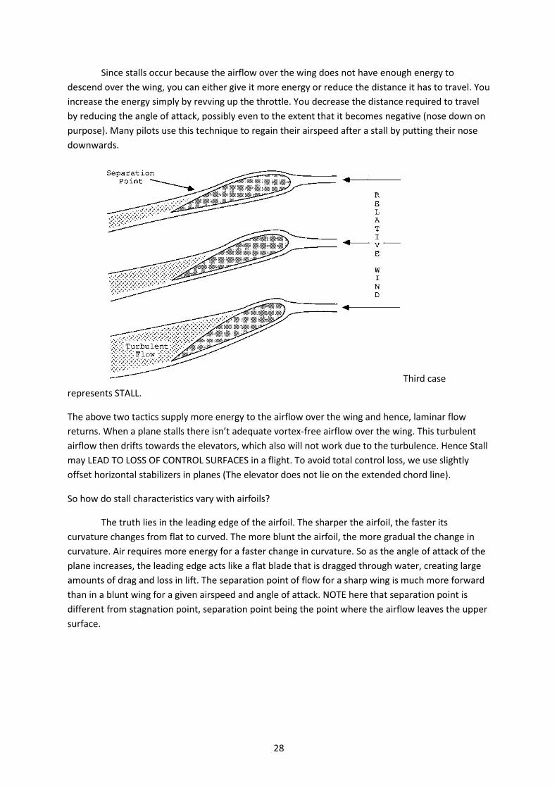
Since stalls occur because the airflow over the wing does not have enough energy to
descend over the wing, you can either give it more energy or reduce the distance it has to travel. You
increase the energy simply by revving up the throttle. You decrease the distance required to travel
by reducing the angle of attack, possibly even to the extent that it becomes negative (nose down on
purpose). Many pilots use this technique to regain their airspeed after a stall by putting their nose
downwards.
Third case
represents STALL.
The above two tactics supply more energy to the airflow over the wing and hence, laminar flow
returns. When a plane stalls there isn’t adequate vortex-free airflow over the wing. This turbulent
airflow then drifts towards the elevators, which also will not work due to the turbulence. Hence Stall
may LEAD TO LOSS OF CONTROL SURFACES in a flight. To avoid total control loss, we use slightly
offset horizontal stabilizers in planes (The elevator does not lie on the extended chord line).
So how do stall characteristics vary with airfoils?
The truth lies in the leading edge of the airfoil. The sharper the airfoil, the faster its
curvature changes from flat to curved. The more blunt the airfoil, the more gradual the change in
curvature. Air requires more energy for a faster change in curvature. So as the angle of attack of the
plane increases, the leading edge acts like a flat blade that is dragged through water, creating large
amounts of drag and loss in lift. The separation point of flow for a sharp wing is much more forward
than in a blunt wing for a given airspeed and angle of attack. NOTE here that separation point is
different from stagnation point, separation point being the point where the airflow leaves the upper
surface.

29
2.6) CENTRE OF PRESSURE OF LIFT
Centre of pressure of lift is the most important property of an airfoil. It is the point at which the resultant upward forces act on an airfoil. It varies with the angle of attack. For angles of attack less than 2o, the centre of pressure of lift moves behind. For angles of attack between 2o and 8o, the centre of pressure of lift moves forward (towards the nose) and then on increasing it beyond 8o, it moves back again. For a fixed airfoil shape, it is important to know the relative the positions of the centre of lift and the centre of gravity. In normal flights, the angle of attack varies between 2 and 8 degrees, and hence pitching the nose up results in the forward movement of the centre of lift. For stability purposes, it is made sure that the CG is in front of the CL.
2.7) POWER AND DRAG
One of the most important concepts for understanding flight is that of the power
requirements. In aeronautics textbooks the discussion of drag, which is a force against the motion of the airplane, would come first and power would be given little consideration. That may be appropriate for the design of an airplane, but it is less useful for the understanding of its operation. Power is the rate at which work is done. The power associated with flight also relates to the demand placed on the engine and the limitations on airplane performance. We will consider two types of power requirements.

30
The first is induced power, which is the power associated with the production of lift. It is equal to the rate at which energy is transferred to the air to produce lift. So when you see the word =induced with respect to flight, think of lift. The second power requirement we need to consider is parasitic power. This is the power associated with the impact of the air with the moving airplane. The total power is simply the sum of the induced and parasitic powers.
INDUCED POWER
Let us first look at the induced power requirement of flight. The wing develops lift by
accelerating air down. Before the wing came by, the air was standing still. After the wing passes, the air has a downward velocity, and thus it has been given kinetic energy. Since the induced power is the rate at which energy is transferred to the air, it is proportional to the amount of diverted air times the vertical velocity squared of that air. (Remember that in the rest frame of the observer on the ground the direction of the downwash is down.) But since the lift of a wing is proportional to the amount of air diverted times the vertical velocity of that air, we can make a simplification.
The induced power associated with flight is proportional to the lift of the wing times the vertical velocity of the air. (P = F x V)
Induced Power PInd is proportional to energy times the frequency or
PInd = (Energy of air) x (frequency)
Here, assuming level flight, the frequency factor becomes a constant and can be
incorporated into a proportionality term in this equation. Thus, the equation can be rewritten as
PInd = C1 x mair x (vair)2 - (1)
We also know that lift force is generated due to the momentum that the plane imparts to
the air it travels through. Hence,
Flift = C2 x mair x vair - (2)
From (1) and (2) we can tell that the induced power is related to lift as
PInd = Flift x vair
So now that we have a relation between Induced power and lift force, what is going to
happen if we tweak around with the plane a bit?
Let’s say that we increase the velocity of the plane vp two times. Now the plane is moving at
twice its speed and hence, is picking up twice the amount of air. To maintain the same lift force for
level flight, the velocity imparted to the air will have to be halved by changing the angle of attack
correspondingly. But since Flift is a constant, Induced power gets reduced to half its original amount
by the above equation. Hence we can safely draw the relation between Induced power and the
velocity of the plane as
Pind = C/vair
31
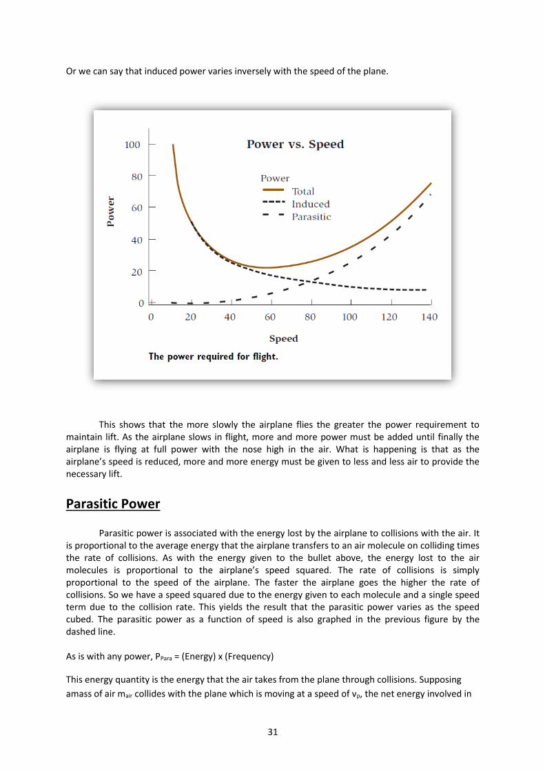
Or we can say that induced power varies inversely with the speed of the plane.
This shows that the more slowly the airplane flies the greater the power requirement to maintain lift. As the airplane slows in flight, more and more power must be added until finally the airplane is flying at full power with the nose high in the air. What is happening is that as the airplane’s speed is reduced, more and more energy must be given to less and less air to provide the necessary lift.
Parasitic Power
Parasitic power is associated with the energy lost by the airplane to collisions with the air. It is proportional to the average energy that the airplane transfers to an air molecule on colliding times the rate of collisions. As with the energy given to the bullet above, the energy lost to the air molecules is proportional to the airplane’s speed squared. The rate of collisions is simply proportional to the speed of the airplane. The faster the airplane goes the higher the rate of collisions. So we have a speed squared due to the energy given to each molecule and a single speed term due to the collision rate. This yields the result that the parasitic power varies as the speed cubed. The parasitic power as a function of speed is also graphed in the previous figure by the dashed line.
As is with any power, PPara = (Energy) x (Frequency)
This energy quantity is the energy that the air takes from the plane through collisions. Supposing
amass of air mair collides with the plane which is moving at a speed of vp, the net energy involved in
32
the collision will be (1/2) x mair x (vair)2. Also, the frequency of collisions will increase linearly with the
velocity of the plane, we have that the net term on the right hand side can be written as
Ppara = C x mair x (vair)3
Or that parasitic power is proportional to the cube of the velocity since all the quantities on the right
hand side become constants and can be taken into proportionality sign
The fact that the parasitic power varies as the airplane’s speed cubed has an important consequence on the performance of an airplane at its cruise speed, where it is limited by the parasitic power. In order for an airplane to double its cruise speed, it would have to increase the size of its engine by eight times! So when an airplane owner upgrades to a larger engine, there is an improvement in the rate of climb and turn of the airplane but only a modest increase in cruise speed. To substantially increase the speed of the airplane, the parasitic power must be decreased. Such design features as retractable landing gear, smaller fuselage cross sections, and an improved wing design accomplish this.
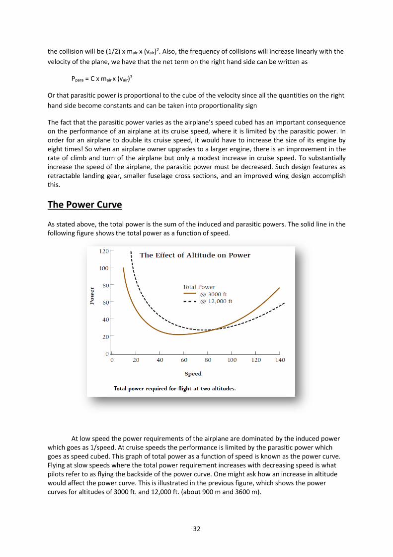
The Power Curve As stated above, the total power is the sum of the induced and parasitic powers. The solid line in the following figure shows the total power as a function of speed.
At low speed the power requirements of the airplane are dominated by the induced power
which goes as 1/speed. At cruise speeds the performance is limited by the parasitic power which goes as speed cubed. This graph of total power as a function of speed is known as the power curve. Flying at slow speeds where the total power requirement increases with decreasing speed is what pilots refer to as flying the backside of the power curve. One might ask how an increase in altitude would affect the power curve. This is illustrated in the previous figure, which shows the power curves for altitudes of 3000 ft. and 12,000 ft. (about 900 m and 3600 m).

33
With an increase in altitude, there is a decrease in air density. Thus, the wing diverts less air and the angle of attack must be increased in order to maintain lift. As stated before, as the density of the air is reduced, the angle of attack, and the vertical velocity of the downwash, must be increased to compensate.
Thus, the induced power would be increased. A 10 percent reduction in air translates to approximately a 10 percent increase in induced power. An airplane flying on the backside of the power curve would require more power and fly with a greater angle of attack when going to a higher altitude. The situation is the opposite for the parasitic power. A reduction in air density translates to a reduction in the number of collisions with the air, and thus there is a reduction in the parasitic power.
An airplane at cruise speed where parasitic power dominates finds it more economical to fly at a higher altitude. Usually flying at a higher altitude does not translate into flying at a higher speed because non turbocharged engines experience a reduction in power that is similar to the reduction in atmospheric pressure. That is, if the atmospheric pressure is 65 percent that of sea level, the maximum power of the engine is also approximately 65 percent of its sea-level performance.
The Effect of Load on Induced Power
Now let us examine the effect of load on induced power. First, remember that the induced power associated with flight is proportional to the lift of the wings times the vertical velocity of the downwash. Now if we were to double the load, maintaining the same speed, we would have to double the vertical velocity of the air to provide the necessary lift. Both the load and the vertical velocity of the air have been doubled and the induced power has gone up by a factor of 4. Thus, the induced power increases as the load squared. It is easy to see why the weight of an airplane and its cargo is so important. The following figure shows the data for the relative fuel consumption of a heavy commercial jet as a function of weight.

34
These measurements were made at a fixed speed. From the data one can estimate that at a gross weight of 227,000 kg and a speed of Mach 0.6 about 40 percent of the power consumption is induced power and 60 percent is parasitic power. In reality the airplane would cruise at a speed of around Mach 0.8, where the induced power would be lower and the parasitic power consumption would be higher. Unfortunately, at that more realistic speed the details of the power consumption become more complicated and it is more difficult to separate the parasitic and induced powers from the data. The induced power increases as the load squared.
Drag So far, we have discussed power at length with only brief references to the topic of drag.
With an understanding of power we are in a position to understand drag, which is part of the pilot’s culture and vocabulary. Drag is a force that resists the motion of the airplane. Clearly, a low drag airplane will fly faster than a high-drag airplane. It will also require less power to fly the same speed as the high-drag airplane. So, what is the relationship between power, drag, and speed? Power is the rate at which work is done. In mathematical terms it is also a force times a velocity. Drag is a force and is simply equal to power/speed. We already know the dependence of induced and parasitic powers on speed. By dividing power by speed, we have the dependence of drag on speed. Since induced power varies as (1/VPlame), induced drag varies as (1/Vplane)2. Parasitic power varies as speed cubed, so parasitic drag varies as speed squared. The following figure shows the dependence of induced, parasitic, and total drag on the speed of the airplane.

35
In the section preceding this one we saw that the induced power increases as load squared. Since drag is just power divided by speed, induced drag also increases as load squared. Anything understood about power can be easily converted to a similar understanding of drag by simply dividing by speed. We have said that drag is part of a pilot’s culture and vocabulary. That is true. But most of the time when the term is used, the person really means power. Let us look at an example to illustrate.
Take the case of a pilot flying a small plane with retractable landing gear. If full power is applied in straight-and-level flight, the airplane accelerates to some speed and goes no faster. A pilot might well say that the airplane’s speed is limited by the drag. Let us pretend that an airplane had two meters, one that measured total drag and another that measured the total power for flight. We will then record both values for the airplane at its top speed. The pilot lowers the landing gear and flaps, leaving the engine at full power. There is now a substantial increase in the drag and power required. This of course slows the airplane down. We would find that the airplane slowed down to the previous total power requirement and now the total drag is higher than before.
The pilot would have to reduce power to bring the total drag down to its previous value. Its
top speed was not determined by the total drag but by the total power (drag times speed). So, when pilots say drag they usually mean power. The utility of the concept of power over drag for the pilot is fairly easy to understand. Power requirements relate simply to the demands on the engine. Drag is a force that must be related to the airplane’s speed in order to understand the related power requirement to overcome it. A drag of a certain value at one speed is only half the power drain of a drag of the same value at twice the speed. In the end, the power available from the engine is what counts.

36
LIFT V/S DRAG:
The major purpose of any common aircraft would be to obtain maximum lift and maximum speed at the same time. Alternatively it would require its wings to give highest lift with the least amount of drag. Hence, we define the term LIFT TO DRAG RATIO. This ratio varies with the angle of attack of the airfoil. From the graph below it can be seen that the ratio is maximum at 3 to 4 degrees. This indicates the maximum efficiency angle of attack for a particular airfoil.
2.8) BASIC FLIGHT
Flight in itself is a very complex phenomenon and requires several analytical tools to help in
characterizing it. The most basic ones associated with the flight are the coordinate systems that
characterize the plane. We will be dealing with only one coordinate system extensively and this is
the Body Cooridnate System
The following diagram should explain the 3 axes of a plane:
X Axis -> from the centre of gravity to the nose of the plane
Y Axis -> from the centre of gravity to the right wing
Z Axis -> from the centre of gravity downwards towards the earth.
Fig: The body coordinate system
Note that the body coordinate system does not take into account the changes due to wind,
earth motion, etc. This is because it is stuck to the plane and oriented along the plane’s nose.
However, the plane need not necessarily move in the direction that its nose is pointing, as is the case
in crosswind landings
The plane’s orientation however, can be characterized by its rotation about these three
axes. As with any 3D body in a coordinate system, the plane can rotate about its 3 axes and each
rotation about the axes has a different name.
X-Axis -> Roll (Changing the plane’s “bank angle”)
Y-Axis -> Pitch (Changing the up down attitude of the plane’s nose)

37
Z-Axis -> Yaw (Changing the left right motion of the plane’s nose, i.e., heading)
There exist mechanisms on the plane that help it to revolve about these 3 axes of motion.
THE FORCES OF FLIGHT
Basic aerodynamics states that any flying body has four forces associated with it. They are as follows:
1. In the forward direction – Thrust
2. In the reverse direction – Drag
3. In the upwards direction – Lift
4. In the downwards direction – Right
If all these forces are in equilibrium, the result is a plane flying in straight and level flight.
This is why to make a plane faster, the engines are not made bigger too often but the plane is made
more streamlined. As to why this is in greater detail, we will deal with in a later section.

38
CHAPTER 3
ELEMENTS OF RC
FLYING
3.1) INTRODUCTION
Hello and welcome to the wondrous world of RC flying, where planes become smaller and
smaller until they can land in the palms of your hands. This world has become the single focus of
many famous aeromodellers throughout time starting from Leonardo Da Vinci to our very own Aero
Club BPGC. Several people pursue this as a hobby and a slightly smaller group take it up as a part of
their professions. Through your tenure at BPGC, we hope that you also actively take part in this
world and win several accolades as result of your passion.
RC flying as such is a diverse field with many different phases and stages, each with its own
sub categories and each with its own set of specialized people. Many have simply gone into making
39
scale models all the way till flying to several hours every day in their nearby farms and fields. To set
you a clearer picture, this chapter will broadly break down the stages of RC Planes overall and give
you a better idea of what all is involved in building a plane and flying it. The following are some of
the broadest stages involved in flying a plane.
a. Theory
b. Planning, Deciding on a design
c. Buildling
d. Flying
3.2) THEORY
An extremely important of flying and building is to learn why things are done the way that
they are. Theory must begin with a fundamental knowledge of how planes and other flying objects
keep up in the air. Theory must consist of why planes are designed the way they are and why they
look and move the way they do. One should also be familiar with the options available and the
compromises related to a particular wing design. (For example, planes with flaps increase lift
efficiency but result in nose down pitching motion). It must also involve a learning of the different
materials and tactics that are used to build a plane. Theory must also comprise of a knowledge of
what all can go wrong during the different stages of RC flying. Ultimately, theory means knowing
what is before ever coming in contact with the actual incident or object.
3.3) PLANNING, DECIDING ON A DESIGN
Now that you’ve learnt why planes are the way they are, it’s time to design your own plane.
Generally, amateur modellers go with previously created plans or designs as per the kind of plane
that they want. Once you have gone to higher levels, you may attempt to design your own plane.
The plane’s design must comprise of its structural aspects such as fuselage lengths, wingspan, chord
length, airfoil shapes, aspect ratios, wing loading, materials and building process. It must comprise of
the designs and calculations for the power house, servos, batteries, ESCs, gyros etc., and how and
where they will be mounted on the plane.
A final blue print of the plane must be drawn and approved by experienced modellers. Once
the blue print has been checked top to bottom, we proceed with the construction.
3.4) BUILDING
This part of the process will determine whether your plane will fly true or fall to the floor after take-
off. Building involves putting together materials and tools together with your own intuition and

40
knowledge to make a plan into a functional machine. The building process is a slow process and in
fact, is required to be done as slowly as possible to leave scope for mistakes. Take your own time
while building a plane and do not be hurried along by others. If there is a due date for the project’s
construction, start building soon enough to leave time for slow building and for several test flights
and modifications.
Most important part of the building process is REASONING and FORESIGHT. One must be
able to account for the task being done and should have the next few immediate steps planned in
his head.
Before building, check your design one last time just to make sure. While building, keep
checking your design to make sure that all the corresponding limits are kept within and that no
mistakes are made.
There is much more to building as you will come to see in the building chapter. Concentrate
while building and do not have any distractions as it is a delicate process and even the smallest of
errors can come back to haunt you in flight.
3.5) FLYING
You’ve built your plane. Now it’s ready to do what it was built for and meant to do – take to
the skies. Flying is a process that requires constant and unwavering concentration and an immense
sense of spatial orientation. Not everyone can fly as soon as they pick up a control. Several countries
require even RC pilots to be licensed before lifting up a controller.
Since you are not exactly sitting in the pilot’s seat, left is not always left and right is not
always right. Another frequently faced problem is the loss of orientation of the plane. When you lose
sense of what direction the plane is facing in, it is very easy to move the control stick in the wrong
direction and end up in a crash. Some of the most famous large scale air crashes have been caused
due to failure of orientation instruments (like horizon indicator and GPS systems).
Flying is an interesting process involving perception and response. When we see the plane
veering left when it’s supposed to be going straight, we give the corresponding stick movement to
ensure that the plane is back on track. This repetitive process of giving control input as per the
plane’s reaction is what makes a good flyer. Several high quality computer-guided experimental
planes also work by the same principle.
As with building, flying is a process that involves constant concentration and must be done
with a clear mind and free hands.
3.6) WINDING Up

41
Take a moment to take in this chapter. The entire book has been based on this structure of
thought and this chain of events from design to flight. RC Flying is a passionate hobby for many
people and is also easily accessible to the interested. But once it has been taken up, its activities
must be performed with the utmost concentration and patience. We, the authors, wish you a happy
RC Flying experience.

42
CHAPTER 4
TYPES OF PLANES
**For special types of plane configurations, refer Appendix C

43
4.1) INTRODUCTION
RC flying is a very widespread hobby that involves a large number of people. To cater to the
interests of these people, planes have taken on a vast number of different types and forms that can
be classified on a large number of bases. For this chapter, we will deal with the broadest divisions of
flying aircraft there are:
1. Sailplanes and Gliders
2. Scale model aircraft
3. Trainers
4. 3D flying planes
5. Jet aircraft
6. Pylon racers
Note: In case you’re wondering where the helicopter and Vertical Take Off and Landing (VTOL)
aircraft are, there’s a separate chapter on VTOL aircraft. It deals much more in detail with
helicopters, tricopters and other VTOL aircraft.
In this chapter of the handbook, we will be dealing with the different characteristics of these planes.
A list of the possible topics of discussion is shown below:
1. Structure and materials
2. Flight capabilities and difficulties
Before proceeding with this chapter however, there is a small classification of planes that you must
know. This is based on the ease of construction of the aircraft:
1. Ready To Fly kits (RTF) – RTF kits come with all the parts and electronics assembled and
ready to simply be attached, glued and flown without trouble. They are available in the
market for a wide range of prices starting from 40-50 USD upwards.
2. Almost RTF (ARTF) kits – ARTF kits are similar to RTF kits except that they need a minimum
amount of construction and assembly for about 3 to 4 hours before flying. In case of
elaborate kits, these can go up to 10-20 hours.
3. Balsa/Depron kits – These kits involve laser cut pieces of materials with a plan for putting
them together into planes. They require large amounts of time and extra resources such as
adhesives and tools. They generally do not come with the electronics. These will have to be
ordered separately.
4. Built from scratch – This is the most difficult building process as it involves making a plane
from a mound of materials and tools. These may not have the precision of laser cutting and
industrial assembly but are generally easier to customize.

44
4.2) GLIDERS AND SAILPLANES
Gliders and sailplanes are highly stable high-lift low-drag aircraft that are used to maximize
flying distance with minimal or no thrust. Flying a glider requires special training. It also requires a
specific environment that involves geo-thermals and updrafts to help the plane stay in the air.
Fig: A motor powered glider that uses a retractable fan for thrust. When this fan is out, it offers
thrust but if it is not retracted, it proves to be a large source of drag.
Structure: Gliders in general are built for maximum lift and minimum drag. Hence they have wings
with very high aspect ratios, i.e, very long thin wings. Their fuselages are also minimally small and
have fairings that reduce drag. In general, gliders do not have any on board propulsion systems
although some gliders have retractable (reduced drag) or non-retractable (drag producing) propeller
engines. They have only one main landing gear at the back of the cockpit region of the fuselage.
Sometimes they have a second auxiliary landing gear under the nose.
How do they work?
Because of their high aspect ratios,
1. They require structurally strong rigid wings.
2. They have a higher moment of inertia and hence, are highly roll stable (low angular
acceleration for the same angular momentum)
3. They are high lift devices as they divert more air.
4. They have higher parasitic drag.
Because of their immense roll stability, three channel gliders involving only rudder and
elevator or a combination of both are very popular in training amateur flyers (thin wings, thinner

45
ailerons, less rolling moment, so no ailerons). RC gliders can land without landing gear and can be
taken off without the help of propulsion by a simple hand launch.
The exact science of flying a glider is complex and so is the exact art of flying one. The gliders
that the club flies are propelled but can fly at very low throttles (30%). However, gliders in general
are not structurally capable of high speeds and will begin to vibrate violently at high speeds.
Thing to remember while building and flying:
1. The wing is to be built with a very high aspect ratio, i.e., long thin wings.
2. Reinforce the wing with a strong spar (carbon fiber). This will help to keep the wing rigid.
3. Make sure that all the thrust lines are directed straight back and that all control surfaces
have even throw (throw of a control surface refers to the degree of movement).
4. While flying, keep the speed of the glider low to keep it stable.
5. When gaining height, always do so travelling into a headwind. When you climb into a
tailwind, you have a much higher probability of stalling.
6. Pitch down gradually and not sharply. On sharp pitching down, the increase in air speed will
generate large amount of lift, making the wings flutter and break.
7. Never aim to perform tricks and complex RC maneuvers with gliders.
8. They are excellent first flyers and can be used to train.
9. Difficult to fly close to the ground due to ground effect.
4.3) SCALE MODEL PLANES
Scale model aircrafts can be used to fly once you have become more comfortable with flying
and building tactics. They are exactly what they sound like – scaled down versions of actual planes.
Some of the more popular scale models are World War 2 planes.
Fig: World War 2 P51 Mustang. The actual plane.
46
Structure: These designs are generally made of coroplast, thermocol, Styrofoam and in some cases,
wood and mono-coat. They follow a similar structure to the original World War 2 planes or jet
planes or whatever structure they mimic. Amateur aeromodellers scale plans of the original aircrafts
to make these types of planes. However, most models are propeller driven unlike the original jet
driven designs. However, some designs use ducted inrunners to mimic a jet engine’s intake but
providing the same thrust. (Refer MOTORS >> INRUNNERS)
How do they work:
These planes generate moderate amount of lift. They have moderate aspect ratios with very
less or practically no vortex reducers. They may be hand launched or have landing gears (sometimes
with a tail gear). They require at least 4 channel controls and may employ high lift devices like flaps,
slats, etc. The airfoils used are symmetric airfoils with slight variations made to the under camber.
Points to remember:
1. These planes were manoeuvrable fighters in the day and are naturally built to be less stable
than commercial airplanes. This enhances manoeuvrability by making the plane naturally
unstable and hence, responsive to control movements.
2. It is more difficult to take-off, land and fly these planes as they are more sensitive and fast
and require runway lengths. Take-offs and landings are generally faster for these aircrafts.
3. Since they contain more details such as swept wings and differently mounted wings, care
should be taken during construction to ensure precision.
4. Note that these planes are relatively faster and maneuverable than gliders, they must be
handled with care. Your flight path must be planned before hand in your head.
4.4) TRAINERS
Trainers are used for exactly what their name suggests. Their stability is in between that of
the glider and that of other 3D and pylon racer planes. Most of their wings have a slight dihedral
angle and their chord lengths generally remain constant. They are roll stable due to the dihedral
angle and are simply faster versions of gliders you could say.

47
Fig: The Spadet LC40. One of Aero BPGC’s first coroplast trainer planes.
Structure: These planes have a structure similar to Cessna 172s and 182s – Wings with uniform
chord lengths, mild dihedral of around 5 degrees and a propulsion system that offers enough thrust
for a controllable speed.
How they work: The dihedral angle works as a very efficient roll stabilizer. When the plane rolls due
to disturbances by the wind, it starts moving in an upward spiral by virtue of its orientation with
respect to the wind. If you carefully analyze the upward roll motion of the plane, it can be noticed
that by virtue of the dihedral, one wing is relatively parallel to the ground than the other (provided
the roll disturbance is small). The angle of attack on the raised wing is reduced and consequently,
the flatter wing gets more lift, giving an opposite roll moment. Hence, the plane is roll stabilized.
Points to remember:
1. Trainers are good practice for building and are the simplest types of attachable-wing low
speed aircraft.
2. Do no risk any tight maneuvers or high speeds. Trainers were made to be handled gently.
3. They are a low to medium speed models. Good for practicing landing, take-off and simple
tricks on.
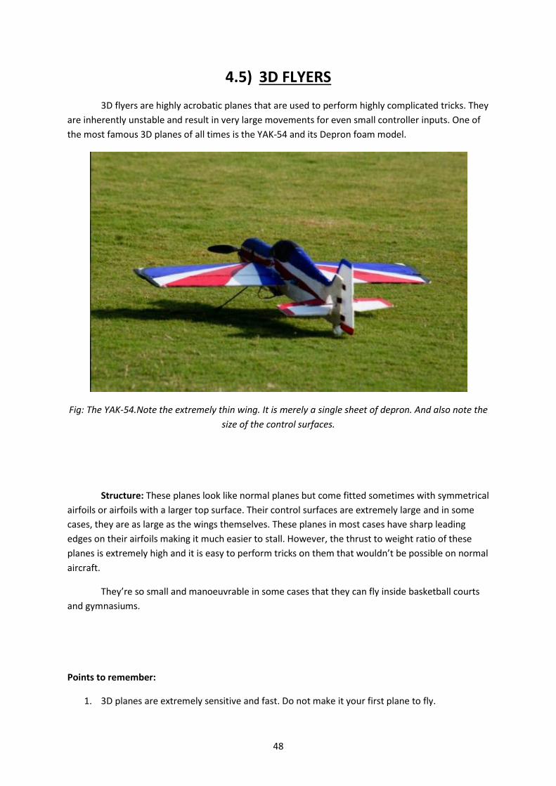
48
4.5) 3D FLYERS
3D flyers are highly acrobatic planes that are used to perform highly complicated tricks. They
are inherently unstable and result in very large movements for even small controller inputs. One of
the most famous 3D planes of all times is the YAK-54 and its Depron foam model.
Fig: The YAK-54.Note the extremely thin wing. It is merely a single sheet of depron. And also note the
size of the control surfaces.
Structure: These planes look like normal planes but come fitted sometimes with symmetrical
airfoils or airfoils with a larger top surface. Their control surfaces are extremely large and in some
cases, they are as large as the wings themselves. These planes in most cases have sharp leading
edges on their airfoils making it much easier to stall. However, the thrust to weight ratio of these
planes is extremely high and it is easy to perform tricks on them that wouldn’t be possible on normal
aircraft.
They’re so small and manoeuvrable in some cases that they can fly inside basketball courts
and gymnasiums.
Points to remember:
1. 3D planes are extremely sensitive and fast. Do not make it your first plane to fly.

49
2. Learn 3D planes under a trainer cable only after your senior tells you that you are ready.
3. Fly trainers first.
4. While trying new tricks for the first time, fly at a high altitude on a day with no wind.
5. Only when you are good enough and confident, must you attempt to fly indoors.
6. While building, ensure that your control surfaces are symmetrical about the line of thrust
7. While building, ensure that your control surfaces are adequately large and that servo throws
in either direction are also very large. The sensitivity can be reduced later.
4.6) JET AIRCRAFT
Jet aircraft are...well... jet propelled. They are generally very fast and highly maneuverable to
make quick moves at that high speed. They fly at much higher altitudes and hence, are difficult to
keep track of in the sky. The jet engines need powerful fixtures to keep it from ripping straight out of
the plane and the aircraft must also be heat resistant. Coroplast and Styrofoam will melt on contact
with heat.
Fig: A jet RC plane. For size comparison, not the car tail lights in the background
Structure: They are generally made of fiberglass, titanium or carbon fiber. Their shapes and
sizes look like conventional aircraft. They may either be scale models or other RC planes. The fuel

50
tanks are lined with Kevlar for the jet fuel. Wings are generally swept backward and have a delta
wing configuration.
Points to remember:
1. Before flying one, you must have a license from the AMA. These are seriously amped up
planes.
2. They are capable of flight speed of over 300 kmph and hence, require flight path planning
and very quick reflexes.
3. Military bases sometimes have restricted airspaces to fly these planes.
4. Ducted fans are not as fast and are much safer. They can be used to train for the actual
thing.
4.7) PYLON RACERS
Pylon racers are low drag planes that are capable of flying at very high speeds and handling
at high maneuverability. They are used for racing around pylons. One can say that they are lighter,
much faster versions of trainers and 3D aircraft
Structure: Not much to say really. They have streamlined shapes but fly at much higher speeds.
They are generally built hollow and with fibre glass to reduce overall weight and to increase strength
at loading points.
Point to remember:
Pylon racers are built for speed and for making tight turns at those speeds. Hence, the following
must be observed
1. They are very fast and require a fair amount of training and experience to handle carefully
2. They undergo vast stresses during turns, climbs and other manoeuvres. Hence, reinforce the
appropriate parts of the plane as needed.
Fig: The streamlined smooth body of a pylon racer with relatively thinner wings than other aircraft.

51
CHAPTER 5
VTOL AIRCRAFT

52
5.1) INTRODUCTION
There are several different categories of take-off and landing methods. They are classified
based on the runway requirements for an aircraft to take off and land.
1. CTOL – Conventional Take Off and Landing
2. STOL – Short Take-Off and Landing.
3. STOVL – Short Take-Off Vertical Landing.
4. VTOL – Vertical Take-Off and Landing.
5. V/STOL – Vertical and/or Short Take-Off and Landing.
This chapter strictly deals with the different types of VTOL aircraft classified based on their
methods of propulsion and lift.
1. Helicopter.
2. Multi-rotor
3. Other special aircraft.
Since the experience of the club encompasses only multi rotor aircraft such as the tri and
quad copters, we will be covering those in better detail than helicopters.
Fig: A Helicopter.
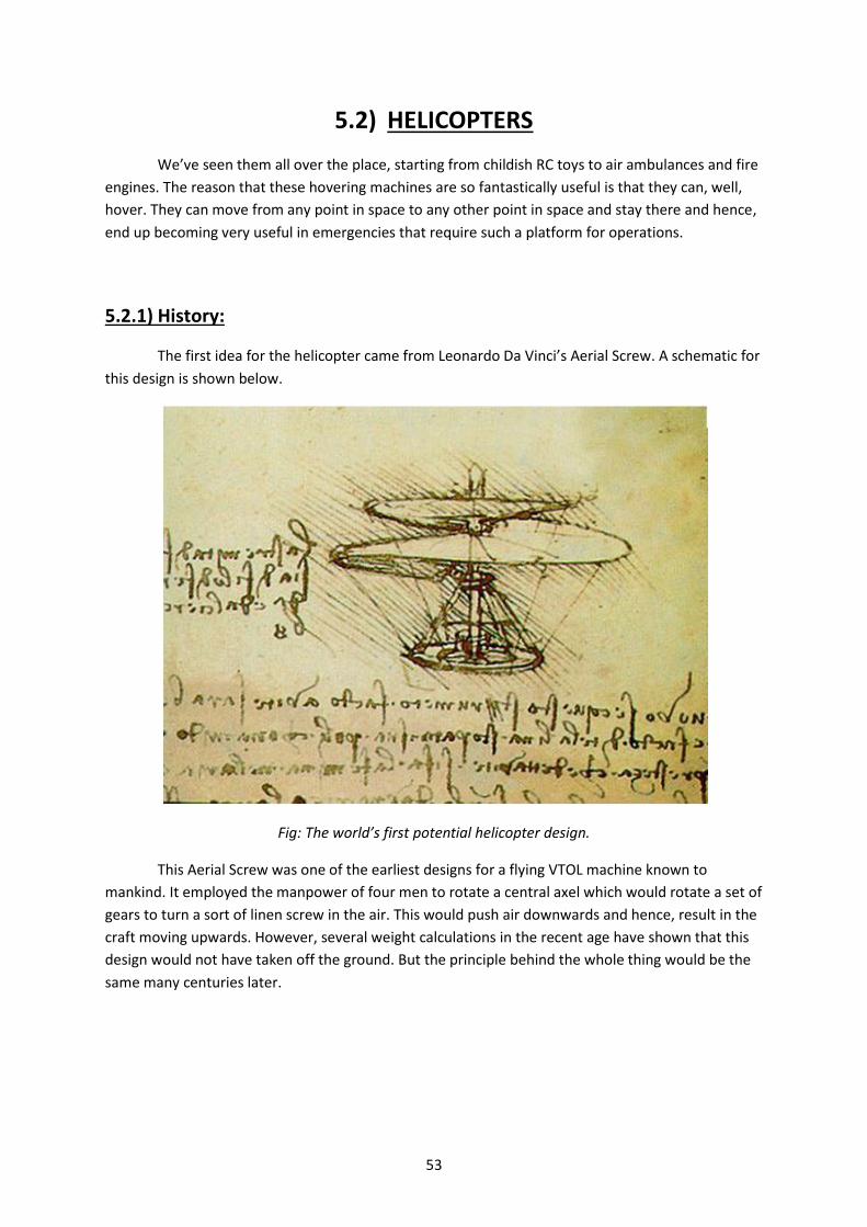
53
5.2) HELICOPTERS
We’ve seen them all over the place, starting from childish RC toys to air ambulances and fire
engines. The reason that these hovering machines are so fantastically useful is that they can, well,
hover. They can move from any point in space to any other point in space and stay there and hence,
end up becoming very useful in emergencies that require such a platform for operations.
5.2.1) History:
The first idea for the helicopter came from Leonardo Da Vinci’s Aerial Screw. A schematic for
this design is shown below.
Fig: The world’s first potential helicopter design.
This Aerial Screw was one of the earliest designs for a flying VTOL machine known to
mankind. It employed the manpower of four men to rotate a central axel which would rotate a set of
gears to turn a sort of linen screw in the air. This would push air downwards and hence, result in the
craft moving upwards. However, several weight calculations in the recent age have shown that this
design would not have taken off the ground. But the principle behind the whole thing would be the
same many centuries later.

54
5.2.2) Structure:
The fuselage: It is a sort of cabin for housing the pilot, cargo and passengers. It also
supports the mount of the engine, the blades, the undercarriage and the tail fixture also. A long thin
tail is attached to the fuselage at its rear. This tail has a much small pair of blades located all the way
at the end. These blades help control the yaw rates of the helicopter as will be explained later.
The rotor blades: They are miniature wings that rotate at high speed and can vary their
angle of attack
A more popular RC structure is counter rotating propellers. Two sets of blades are mounted
on the same axis, rotating in opposite orientations. Since these sets of blades are equal in mass,
their moments of inertia are the same and hence, the net torque on the fuselage cancels out. In
these cases, a small mini rotor is located on the tail pointing in the negative Z-axis (upwards). This
rotor controls the pitch of the aircraft.
Note: Please make a note of the difference between pitch of the aircraft and pitch of the blades.
5.2.3) Working principle:
The blades have a cross section very similar to an airfoil. As these blades rotate through the
air, air is pushed downwards. This, in turn, pushes the aircraft upwards, thus creating lift. The angle
of attack of these individual blades can be varied by a technology known as CCPM which will be
explained later.
Since these blades are much larger and much more torque is involved, they create enough
angular momentum to make the helicopter rotate in the opposite direction for conservation’s sake.
This counter rotation is, in turn, corrected by a tail rotor that is mounted with its axis in the plane of
rotation. The angles of attack of these tail blades can also be changed to vary the rate of yaw.
These angles are not exactly angles of attack. We simply use the terminology for
understanding’s sake. This angle is known as the pitch angle of the blades. The steeper that pitch
angle, the more the air diverted downwards. But the stepper the pitch angle, the more the drag
force on the rotor blades, which will decrease efficiency.

55
5.2.4) Aerodynamics:
The normal lift profile of a vertical rotor aircraft looks as follows:
Note that some of the downwash from near the wingtips cycles back over the rotor back
into the rotor’s downwash again. This gives rise to a toroidal ring of airflow around the
circumference of the rotor.
The most important thing that can go wrong with a vertical rotor is similar to the stall of the
plane. The airflow over the rotor has two components.
a) Downflow – The air that the rotors push down.
b) Upflow - The air that flows back over the plane by virtue of its descent rate.
In general, the airflow over the top of the wing is laminar and below is turbulent. When the
upflow starts to overwhelm the downflow, the air flow over the top of the rotor becomes turbulent
and the plane experiences a loss of lift and descends further into its own downwash. This is an
irrecoverable state and often results in the crash of the aircraft.
As you would have noticed in the above diagram, the airflow is faster and more voluminous
towards the rotor tips. As upflow retards the downflow, the airfoil of the rotor closest to the rotor

56
hub begins to stall, creating vortices. These vortices radially radiate outwards and progressively
begin to decay lift until the plane effectively loses its lift and begins a further descent.
Here, the aircraft descends into what is known as the Vortex Ring State or does what is
known as Settling With Power.
This most frequently occurs during phases when the plane experiences an increase in the
upflow of the rotor.
a) During landing, if the plane descends too fast.
b) During descent, if the plane does not have adequate forward velocity.
c) During the transition from ground effect to minimum hovering ceiling.
5.2.5) Movements:
a) Throttle: The aircraft is tilted forward to change a component of lift into thrust. Throttle is
increased to balance out the corresponding loss in lift and to propel the plane forwards.
b) Yaw: Yaw is controlled in a normal helicopter by the reduction or increase of the pitch angle of
the tail rotor blades. This controls the amount of air that this rotor pushed sideways. By varying the
amount of air flowing over the critical equilibrium position to counter the torque of the engine, yaw
can be controlled
57
c) Pitch and Roll using CCPM: Pitch and roll are controlled in a similar manner on a helicopter –
through CCPM. CCPM means Collective Cyclic Pitch Mixing.
A CCPM system, broken down to the fundamentals, is basically a swash plate paired with the
rotating axis of the engine. This system is used to differentially vary the pitch angle of each blade as
it passes over a specific point in the 360 degree circuit of the rotor. This increases or decreases lift on
that section and hence, makes the aircraft tilt in that direction. This is followed by an increase in
throttle due to the decrease in lift component due to the tilt of the aircraft. This increase in throttle
propels the aircraft forward. For more details on CCPM technology, refer to the following links.
For example, if I wanted to pitch my aircraft forward, the following would happen.
1. The swash plate would tilt forward.
2. As each blade passes over the tilted section, its pitch angle decrease to a small or possibly a
negative value just for that instant. And as each blade passes over the back of the tilted
section, the angle of attack correspondingly increases.
How does this happen?
In several operations, a section of the blade is attached to a rotating plate on the swash
plate. As the plate tilts forward, the distance between that section of the plate and the
rotating plane of the blade increases. This increase in distance makes airfoil tilt downwards
to compensate, hence reducing its angle of attack.
NOTE that the above is used in RC aircraft. The technology may vary from model to model
3. This varying angle of attack creates an increase in lift on one side and a corresponding
decrease in lift on the other. Therefore the aircraft tilts.
Note: As of the summer of 2012, the Aerodynamics Club, BPGC has not experimented with
the flying of helicopters. However, a rough guide to flying VTOL aircraft will be covered in a separate
section later in this section.
5.2.6) INTRODUCTION TO CCPM AND HELI SWASHPLATE
More and more recently introduced machines are using some form of moving swashplate
system incorporating Cyclic/Collective Pitch Mixing (CCPM). They can take many forms and the essential mixing can be accomplished mechanically, electronically, or by a mixture of both.
In order to understand just what is involved in a moving swashplate system, let's first explain how a fixed swashplate works. In its simplest form, only two inputs are required (Fig.1). One link tilts the swashplate in a fore/aft direction and the other in a lateral direction. The centre of the swashplate is a large ball joint which is fixed in position on the main shaft. On the recently introduced 'Hornet' electric helicopter, the swashplate is fixed in its position by the links going up to the flybar. Some systems use more than two inputs which serve to steady the swashplate and give more precise control (Fig.2). This arrangement is normally only found on the higher priced competition machine.

58
The essential point here is that a fixed swashplate system uses some other way of changing the collective pitch of the rotor blades. A moving swashplate moves up and down to control the collective. For all practical purposes, CCPM means 'moving swashplate'.
3 and 4 input systems
If a swashplate is to move up and down with pitch variation and still give satisfactory control of the cyclic inputs to the blades, it must be held firmly in any given position. This requires a minimum of three inputs, or operating links. These can be spaced at 90 degrees to each other (Fig.3) or at 120 degrees (Fig.4).
90 degree spaced inputs are normally arranged so that there is one on each side and one at the front (or rear). The inputs at each side move in opposition to each other for lateral cyclic control (aileron), and the front input moves to give fore/aft cyclic (elevator) control (Fig.5). All three links move together for collective control.
There is, of course, no reason why there should not be two linkages at front and rear, moving in opposition, for elevator control and a single linkage at one side for aileron control. However, we are not aware of any model which has used this system.
When the inputs are spaced at 120 degrees, there are two arrangements which can be used. One (Fig.6) has one link at the front and links at either side, similar to a 90 degree system, but the side links are further to the rear. The actual control inputs for this system are rather more complicated, since the cyclic inputs cannot be totally separated.
For example, when the front link is moved up and down for elevator control, the whole swashplate will move up and down unless the two side links are moved a smaller amount in the opposite direction to compensate (Fig.7). The two side links will still operate the aileron input as before.
Once again, the same linkage can be used with the single link at the back and the side links fitted a little to the front of the side location (Fig.8).
Another variation on this particular set-up is as shown in Fig.9. Here the single side link will give lateral control, with some opposite compensation from the other two, while the fore and aft linkages will move in opposition to each other for elevator control. However, this is not a common arrangement.
The final variation, which gives even more support to the swashplate, has four links at 90 degrees to each other (Fig.10). Here both axes are controlled by a pair of links moving in opposition, with all four moving together for collective control.
The manner in which these swashplate movements are communicated to the blades varies from model to model and does not concern us here. The basic points to remember are:
1) The fixed swashplate tilts in the direction that the helicopter is required to move. Collective pitch control is affected by the mechanism described earlier.
2) The moving swashplate has two functions. It tilts in the direction that the helicopter is required to move, and it moves up and down to control the helicopters height.

59

60

61
5.3) TRICOPTERS
Tricopters are VTOL aircraft with a very unique structure that can manoeuvre without the
help of CCPM technology simply by using vector thrust and differential throttle. They are unique to
RC builders and are not commercially produced because of the relatively larger and less economic
structure that they have. Helicopters compress all of the directional movements into one single
rotor, thus increasing power efficiency.
5.2.1) Structure: As the name suggests, tricopters have 3 rotors at the ends of 3 long arms each
placed at 120 degrees to each other, thus completing the full 360 degrees. Aero BPGC has used one
of the motors to control yaw by mounting it on a servo motor. However, yaw can be controlled by
varying the RPM of the rotors individually also.
Fig: A simple tricopter.
5.3.2) Movements:
For a reference points, one of the booms/arms of the tricopter is chosen as the tail and the other
two remaining arms become the front of the tricopter. Since it is very possible and very easy to lose
orientation, a different colour or indication must be used to tell between the tail and forward
booms. The tail boom controls yaw and pitch while the arms control roll.
Yaw: The tail motor is mounted on a large servo which connects to the receiver. When the signal is
given, the motor is tilted left or right, thus pulling the tail in that direction. This however, has a small
effect on pitch since the tail component of the lift is decreased when the motor is tilted. Correction
must be given. In other cases, yaw is controlled through a change in the RPM of the motor as RPM is
directly related to the torque of the motor and can hence, cause angular rotation of the craft.

62
Pitch: Pitch can be controlled using the tail motor. The RPM of the tail motor can be increased alone
without the RPM of the arm motors increasing, hence creating a differential lift that lifts the tail of
the aircraft alone. This in turn makes the nose go down and hence, the aircraft’s pitch can be
controlled.
Roll: Roll is controlled with the front 2 arm motors. For example, if the RPM of the left motor was
increased, the left side would lift up further and cause the plane to roll right. It’s generally more
advisable to increase the throttle on the opposite side than to reduce throttle on the same side. This
is because the rotor of a VTOL aircraft can drop through its own downwash, causing a devastating
drop in lift.
Throttle: The pace of the aircraft’s movement is determined by the pitch and roll which are then
coupled with throttle. This helps the aircraft to travel in an required direction.
Fig: A flying tricopter.

63
5.4) FLYING A VTOL AIRCRAFT
Flying a VTOL aircraft is not as simple as flying a plane. Planes are naturally stable and will carry on
even if you switch off the throttle. A VTOL aircraft will simply drop out of the sky at zero throttle. In
case something goes wrong, we cannot simply switch off the throttle and let the aircraft drop to the
ground. Nor can we let the throttle stick go and expect the aircraft to be stable unless it is very well
built. Hence, flying a VTOL aircraft requires constant concentration from take-off to landing.
The stages of flight will be as classified:
1. Take-off and hovering.
2. Moving.
3. Landing and shut down.
4. Emergencies.
Note: Since the procedure for start up depends on the individual aircraft, please refer to another
source on initiation procedures for different VTOL aircraft or ask your seniors until this section
expands.
5.4.1) Take-Off
Take-off is performed by increasing throttle and lifting off the ground while holding the aircraft
steady. That’s the simple version of it. However, holding up an unstabilized or weakly stabilized VTOL
aircraft is a crazy challenge and must be far from your first flying experience.
Note: All of the steps have been written assuming that all pre-flight and trim checks have been
completed. Expansion on this section will be coming soon. This is because the start up process is
different for different VTOl aircraft.
1. Tricopters increase lift by increasing rpm. Helicopters increase lift by increasing pitch.
2. Place your aircraft on level ground and perform the required initiation steps. The aircraft
must be initialized only on level ground as the gyros will read this position as the zero
position. Some tricopters require there to be a minimum amount of non-zero throttle for the
gyros to initialize.
3. Step back from the aircraft and give a good clearance around it.
4. Increase the throttle until the rotor starts generating lift and you see the aircraft begin to
move. This is a very delicate stage.
5. Keep the aircraft level and the nose straight. Increase throttle while doing so.
6. You must now clear the ground effect area. In the ground effect, the vortices generated by
the rotor downwash are greatly reduced in size and hence, doesn’t cause any drag on the
wingtip. This will in turn, cushion up the plane.
The above makes us think that the plane can fly at an rpm much less than what is expected,
but an increase in rotor-lift is still needed. Once the aircraft has cleared ground effect, a drop
in the lift generated is noticed.
7. Try to keep the nose of the aircraft straight in the direction of take-off.
8. Once you have cleared ground effect, increase throttle to gain a height of atleast 6 to 10 feet
while keeping the aircraft steady.

64
Note, not all aircraft are so stable that they can hover once the correct throttle has been
found. Tricopters especially, have a habit of bobbing up and down to adjust to a given
throttle and are very annoying in this aspect.
9. To hover the aircraft, a combination of the above phenomenon and steadying stick
movements must be applied.
5.4.2) TRIM
The trim process is not like an aircraft where it can be done in the air. It is much more difficult to
hold up helicopters to trim than with normal planes where the plane can be let go and will continue
flying. Trimming will take a couple of steps.
1. Follow the take-off procedure till the plane is around 3 to 4 feet off the ground.
2. While maintaining control of all the sticks in the required positions, let go of each one of the
control channels one by one to the mean position and note the aircraft’s motion.
3. Reduce the throttle to just the limit below that required to keep up the aircraft. It will come
down to a slightly bouncy halt.
4. Make all the required changes to trim.
5. Repeat the above steps until the corrections have been made and the aircraft is controllable
with the sticks close to or ON the mean positions.
5.4.3) MOVING
VTOL aircraft generally do not employ control surfaces for their motion and rely on a component
of their lift to be redirected to move in the desired direction. This is better explained for helicopters
in the CCPM technology section. Tricopters vary their rpm on the individual rotors to control their
orientation.
Moving forward:
1. Here, a component of the lift has to be redirected forward to move the plane forward. This
is why helicopters tilt in the direction that they are moving.
2. Give up elevator and the aircraft will tilt forward.
3. Since a component of lift is lost, the aircraft’s rate of ascent slows down. Sometimes to the
point that it loses altitude.
4. The throttle must me increased to a point where lift can be maintained and the plane can
move forward. The steeper the plane leans into the movement, the more throttle is needed
to balance lift.
5. The plane now moves forward.
6. The closer you are to the ground, the less steeply you must move the plane. This is only a
safety precaution in case something goes wrong. The same physics will hold good for any
altitude above ground effect clearance.
7. The next step is to stop moving. This must be done in a special way. The forward movement
must be damped out.
8. Once the plane is moving forward, the forward component must be removed.
65
9. Pull back on the elevator to make the rotor(s) tilt opposite to the direction of the motion.
This redirects a component of the plane’s lift in the backward direction, thus slowing down
the plane.
10. As the plane slows down, the nose must be lowered back down to level flight before the
reverse component takes over the motion of the plane and takes it backward.
11. If done correctly, the aircraft will come to a hovering halt.
12. If not done properly, the aircraft will start moving backward and the process has to be
repeated until the plane has damped out its momentum and it comes to a halt wherever
required.
13. The above principle works for sideways movement also.
5.4.4) TURNING
Turning is a symphony of all three control orientations in a VTOL aircraft just as it is in an airplane.
The yaw in a VTOL aircraft plays a much bigger role in turning than in normal aircraft. This section
opens with the assumption that your aircraft is moving forward.
1. All VTOL aircraft fly by a similar method – redirection of the thrust vector.
2. To put your helicopter or VTOL aircraft into a turn, you must turn similar to how a flying
plane does.
3. Roll your aircraft left or right gradually. As you do so, pull back on the elevator stick to pull
the plane into the turn and increase throttle correspondingly to compensate for the loss in
the component of lift.
4. This increase in throttle is very important because any plane has a natural tendency to lose
altitude while banking for a given amount of thrust.
5. VTOL aircraft also have a tendency FOR ADVERSE YAW. If you do not keep the nose of the
aircraft pointed into the curve, then control inputs might be confusing to the pilot as VTOL
aircraft need not necessarily travel in the direction that they are pointing.
6. Once the plane has encountered the last part of the turn, start to bring the VTOL aircraft
back level just like in a plane to avoid overturning. If one has overturned, refer to the
dampening step in the above MOVING FORWARD section.
7. Turning requires the use of all three control surfaces. Because of the high moments of
inertia and rpm involved, helicopter or VTOL crashes are generally very hazardous when
happening close to humans. Fly VTOL aircraft at a good distance from living beings.
5.4.5) LANDING
1. Firstly, make sure that the landing space is level and empty for a good distance in all
directions from the actual touchdown spot.
2. Only after making sure of this must you bring the plane above this position using the
abovementioned techniques.
3. Once you have positioned the plane, use yaw control to bring it around to the required
orientation.

66
4. As with all lifting forces, there is a point of equilibrium where the aircraft’s weight will
balance its lifting force. This is the point where the aircraft will hold up itself in the same
altitude.
5. Find this throttle first, hold your plane steady.
6. Bring the throttle lever to a minimal amount below this point.
7. Hold the aircraft level while this occurs.
8. IT IS VERY CRITICAL TO NOT DESCEND QUICKLY. If you descend too quickly, you increase the
risk of the aircraft descending into Vortex Ring State.
9. Maintain a small rate of descent.
10. Retain the rate of descent until the plane has touched down. Note that you might see a
reduction in the descent rate as the plane enters ground effect. This is a very delicate
transition and must be eased into very carefully.
11. Once the plane has touched down, kill the throttle. Wait for the rotors to come to a halt
before approaching the plane.
12. Once the aircraft is visibly inactive, hold the throttle at zero and approach the aircraft.
13. Disconnect the battery. Switch off the RC.
5.4.6) EMERGENCY PROCEDURES
Unlike planes, if something were to go wrong with a VTOL aircraft, there would be nowhere to go
but straight down. Emergency procedures regarding VTOL aircrafts require much faster reaction
times than normal aircraft do.
Aircraft descends into vortex ring state:
The airflow over your rotor has become turbulent. What do you do? You must return the airflow
above the rotor area to a laminar flow. There are several places where the VTOL aircraft can enter
vortex ring state:
1. During take-off while clearing the ground effect.
2. In flight when descending too fast without adequate forward velocity.
3. During landing while descending into ground effect.
How do you return air flow to normal over the rotor?
1. If you are high enough, give the plane a component of velocity in any direction, preferably
towards the nose.
2. If your plane is powerful enough, increase the throttle.
Both of these solutions or a combination of both can save the plane. However, if you don’t not react
fast enough, the plane will continually descend into its own vortex and recovery will become
impossible.

67
Loss of torque balancing:
In movies, you might have seen that helicopters, on losing their tail rotor, might go into a rapidly
rotating spiral downwards. It is extremely difficult to control the plane once transition has been
made into this state.
If your CCPM is still active, then you must rotate the control stick in the required direction to
continually increase or decrease the pitch of the rotors so that the plane can be kept in level flight
attitude to try and land it. This tactic is very difficult and requires extensive practise to execute.
Thrust fails in flight:
In general, if your thrust dies, theory tells you that you will fall straight down. However there is a
technique that exists to counter this problem. It is called auto rotation.
Auto rotation: When a VTOL aircraft such as a helicopter has lost thrust, they can cushion their
descent through this tactic. When the aircraft descends, Air pushes from under the rotor. The air
meets the blades, which have an angle of attack. When the air meets the blades, they deflect the
blades into a rotation. This rotation causes more air to be sucked from under, thus compounding the
process further and further. Hence, the net effect is that the helicopter is able to slow down its rate
of descent from a crash to a slightly hard thud.
For training, pilots are required to put their helicopter into this state and be able to bring it out of
the same.

68
CHAPTER 6
PARTS OF A PLANE

69
6.1) INTRODUCTION
Welcome to the “Parts of a Plane” section of the handbook. Here we will be discussing the
several parts of a plane, their types, merits and demerits. The objectives/sections of the following
chapter have been covered below:
1. Parts of the plane in brief with their respective functions.
2. Fuselage.
3. Wings.
4. Ailerons.
5. Tail section
6. Flaps and slats.
7. Landing gear.
8. Other mechanisms.
Under each of the above sections will be several sub sections as follows:
1. Structure.
2. Mechanism.
3. How do they function?
4. What do they affect?
5. Different types – merits and demerits.
Note that this is a large section of theory and it might be healthier if you go through this with a
senior or experienced member of the club. This section of the book is largely theory based and will
be taught in classes and lecture series. Pay good attention and have a nice time learning about
planes.

70
6.2) THE FUSELAGE
6.2.1) Structure
The fuselage is the body of the plane. It is generally symmetric about the XZ plane, i.e., the
starboard and port parts look the same. It is aerodynamically streamlined with minimally small
protrusions and holes, thus ensuring a smooth laminar flow of air along the body of the plane. The
streamlined shape helps the plane to cut through air with minimized frictional drag with air.
6.2.2) Function
The fuselage of the plane has one main function: to house the systems that help to control
the plane. These systems are generally electronic and hence, it is not suitable to leave them open to
the elements. The fuselage guards these systems against aerodynamic forces and exposure to the
elements.
The fuselage also helps in storing payloads. If payloads were stored outside the body, they
would seriously hinder the aerodynamic profile of the aircraft and minimize its efficiency.
The fuselage also helps to direct large volumes of air from the nose to the wings and control
surfaces via the Coanda effect and hence, helps a little in streamlining the flow from the front to the
aft of the aircraft.
6.2.3) Types
On the basis of shape of cross section:
a. Stick Fuselage: Stick fuselages generally consist of only a stick of wood or metal that
supports the motor and servos. The wing is fastened onto the fuselage.
Advantages: Has a very small aerodynamic profile. Is very light weight. Easy and cheap to
build.
Disadvantages: Any small protrusions will cause drag. Very roll unstable. It does not cause a
large amount of air to divert through Coanda effect.
b. Box Fuselage: Box fuselages are the next easiest to build after stick fuselages. They involve
folding or fastening material at sharp angles to make a POLYGONAL cross section. Several RC
aircraft like the LC-40 have such a cross section. This is the most fundamental sort of 3D
fuselage.
Advantages: Easy to build. Significantly larger aerodynamic profile and hence, diverts more
air. Flat surface means easier surfaces to mount mechanisms on.
Disadvantages: Highly prone to compression and torsion forces. Once the body twists, it
heavily affects the aerodynamics of the plane and endangers structural integrity. Sharp
corners affect aerodynamic stability and disrupt laminar airflow and must hence, filleted into
curves.
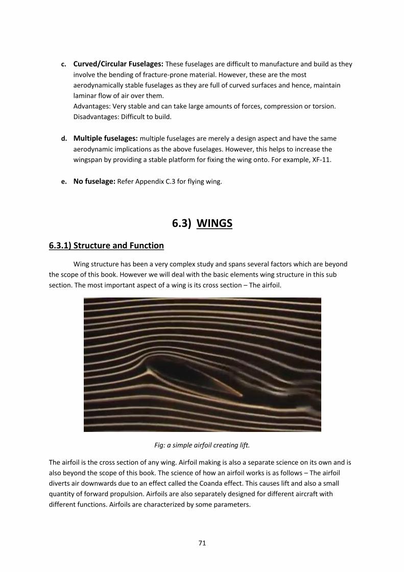
71
c. Curved/Circular Fuselages: These fuselages are difficult to manufacture and build as they
involve the bending of fracture-prone material. However, these are the most
aerodynamically stable fuselages as they are full of curved surfaces and hence, maintain
laminar flow of air over them.
Advantages: Very stable and can take large amounts of forces, compression or torsion.
Disadvantages: Difficult to build.
d. Multiple fuselages: multiple fuselages are merely a design aspect and have the same
aerodynamic implications as the above fuselages. However, this helps to increase the
wingspan by providing a stable platform for fixing the wing onto. For example, XF-11.
e. No fuselage: Refer Appendix C.3 for flying wing.
6.3) WINGS
6.3.1) Structure and Function
Wing structure has been a very complex study and spans several factors which are beyond
the scope of this book. However we will deal with the basic elements wing structure in this sub
section. The most important aspect of a wing is its cross section – The airfoil.
Fig: a simple airfoil creating lift.
The airfoil is the cross section of any wing. Airfoil making is also a separate science on its own and is
also beyond the scope of this book. The science of how an airfoil works is as follows – The airfoil
diverts air downwards due to an effect called the Coanda effect. This causes lift and also a small
quantity of forward propulsion. Airfoils are also separately designed for different aircraft with
different functions. Airfoils are characterized by some parameters.

72
1. Chord length
2. Camber line
3. Angle of attack

73
6.3.2) Apart from the wing’s cross section, the wing is classified on several
different factors:
Aspect ratio – The ratio of wingspan to chord length is known as aspect ratio. This affects the
mobility of the airplane. For example, Gliders have wings with high aspect ratios whereas fighter jets
have lower aspect ratios. Aspect ratio is a measure of the lift generating capability of the plane.
Mathematically, the lift force depends on the area of the wing. However, associated with the lift is a
particular rotational turbulent flow called wing-tip vortex. Wing-tip vortices are unavoidable in a
normal lift generating aircraft. These wing tip vortices are a source of induced drag and depend on
the size of the wingtips. (For tapered wing tips, the side view of the wing is taken as the wingtip
size). For high aspect ratio wings, the wingtip size is less. Hence for the same wing area, the amount
of wing-tip vortices produced is low.
Wing sweep – Wing sweep is the amount by which the wings are inclined to the body. Most
airplanes are backward swept. Backward sweep reduces the power required for a given speed as
compared to a straight wing by directing the airflow along the fuselage all over the wing. Roll
Stability increases with backwards sweep. (How?) So, for higher maneuverability, forward swept
wings may be suitable. Examples – Cessna 172, Boeing 737, X-29, Fighter aircraft in the same order
from left to right as below.
Wing chord - Chord length, as mentioned above, can be varied from wing root to wing tip to give
various top view profiles of wings. The goal of the wing shape is to bring the airflow cross section
above it to an elliptical pattern. (REFER AERODYNAMICS OF FLIGHT SECTION)

74
Dihedral and Anhedral – This is the angle made by the plane of the wing to the XY plane (horizon
plane) Most planes have a dihedral angle as this stabilizes the roll of the plane. Examples from left to
right – Gliders, An-124, Beriev Be-12, Stuka JU87.
Blended Bodies – These involve the body being blended with the wing and the body-wing creating
enough lift to sustain itself in flight. These aircraft divert from the fundamental design of wing and
body and have been one of the biggest fields of aerospace research in the past few decades. Most of
these designs are innately unstable and require computer and sensor aid to fly.

75
Multiple wing aircraft – Well, the name says it all. Multiple wings make the airplane heavier but
generate more lift. There have been problems with the high pressure region of lower wings
interfering with the lower pressure regions of higher wings.
Placement on the fuselage: The position of the wing root on the fuselage determines another
classification of wing types.
The implications of all of these aspects of wing design are very large in number and are beyond the
scope of this book. (Still for a basic explanation refer to Appendix C.2)
6.4) AILERONS
6.4.1) Structure
They are flat panels located on the tailing edge of the wing. They vary in dimensions
depending on the type of aircraft. Stunt and acrobatic planes have very large ailerons that span the
entire span of the wing whereas commercial aircraft have tiny ailerons further out towards the wing
tip. The reason that these ailerons are closer to the wing tip is because of the higher torque that
they deliver as they move further out. However, they are not all the way to the end. This is because
the airflow is more voluminous close to the fuselage than at the wing tips.

76
The sensitivity of ailerons depends on 2 factors:
a. the amount of air flowing over the aileron.
b. the torque that it delivers on the plane.
Because of the above two factors, the placement of an aileron is very specific.
Commercial airliners sometimes have 2 sets of ailerons. One is located closer to wingtip and the
other, near the middle of the wing. Each of these surfaces causes a different torque on the fuselage
and hence, can be used to sensitively control the roll angle of the plane.
Fig: The aileron on the wing indicated in red.
6.4.2) Function:
These help the plane to rotate about the X-axis (axis running from tail to nose through the
CG)
6.4.3) How does it work?
To bank a plane, one aileron goes up and one aileron goes down. This diverts airflow over
one wing upwards and the other, downwards.
The wing that has air flowing upwards pushes the wing down and other wing that diverts air
downwards pushes it up. Hence, the net effect is a rotation about the X-axis.

77
Fig: A diagram indicating the direction of rotation of the plane with varying aileron movement.
6.4.4) Different types of ailerons:
Ailerons come in a variety of shapes, sizes and locations. They can be mixed with elevators and flaps
for different types of mixing. The two main types of mixing are elevons and flaperons.
Elevons: These are a mixture of elevators and ailerons. They are similar to any normal control
surface and look like a panel but are generally located towards the back of the plane. This is because
they need to control the elevator and aileron functions. You will notice that when elevons on both
sides of the plane point in the same direction, they act as elevators and when they point in opposite
direction, they act as ailerons. A good example of this is any delta wing fighter aircraft like the F-22
Raptor.
Fig: Elevon panels on an F-22.

78
Flaperons: These are a mixture of flaps and ailerons. They are generally located slightly behind of
the midline of the fuselage. This is to make sure that they don’t heavily affect the pitch of the
aircraft when used as flaps. In the same above photo, you will notice a set of control surfaces on the
wing that are very close to eh body of the airplane. These drop down as flaps during landing but are
otherwise used as ailerons for sharp turning. They are larger than the smaller pure ailerons located
right beside them.
Fig: The red part indicated flaperon panels and green part shows the smaller pure ailerons
A natural question arises following the aileron explanation.
Will a plane work with only one aileron?
The answer is yes, but in a dysfunctional manner. Since torque is generated by only one side, only
that side of the wing will lift or drop. The plane will not rotate about the X-axis but will instead,
cause the plane to rotate about an axis that doesn’t pass through the tail and nose but is rather,
offset by a distance. Also, the roll will not be as sensitive since with control surfaces, size and
number matters.
6.5) THE TAIL SECTION
The tail section or empennage of the plane is responsible for controlling movements around
the Y and Z axes of the plane. Conventional tail sections have a control surface that deals with pitch
(elevator) and another that deals with orientation (rudder) and the corresponding vertical and
horizontal stabilizers. However there exist a vast variety of tail section designs that vary the
dimensions, location, orientation and mixing of the rudder and elevator control surfaces. These can
lead to excellent new inventions and the resulting implications.

79
6.5.1) Elevators
Structure: Elevators are horizontal control surfaces attached to the tail of the aircraft. They are
designed to control the pitch of the airplane. They are attached to the tailing edges of flat panels on
the tail called the horizontal stabilizers.
How do they function? When the control surface point upwards, it pushes air upwards and as a
consequence, pushes the tail downwards. This causes the plane to lift its nose thus, increasing the
pitch of the nose. The same works in the opposite direction. Horizontal stabilizers help to maintain a
specific pitch level once the plane has been oriented in that direction.
Fig: Demonstration of up elevator.
6.5.2) Rudder
Structure: They are almost the same as elevators except that they are oriented along the vertical
direction. They control the yaw of the plane. They are also attached to the trailing edges of a fixed
panel called the vertical stabilizer which helps to stabilize the plane once a heading has been set.
How do they function? They work by diverting air in one direction and hence, diverting the tail in
the opposite direction. For example, if the rudder points right, it diverts air right, hence, diverts the
tail left and hence, the nose right.
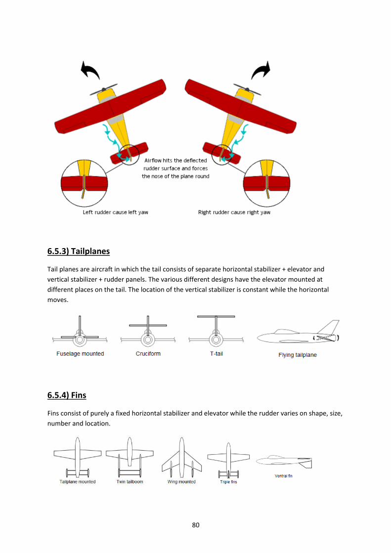
80
6.5.3) Tailplanes
Tail planes are aircraft in which the tail consists of separate horizontal stabilizer + elevator and
vertical stabilizer + rudder panels. The various different designs have the elevator mounted at
different places on the tail. The location of the vertical stabilizer is constant while the horizontal
moves.
6.5.4) Fins
Fins consist of purely a fixed horizontal stabilizer and elevator while the rudder varies on shape, size,
number and location.

81
6.5.5) V and X-tails
V and X tails use the help of panels that are equally inclined to the vertical and horizontal planes to
control yaw and pitch. V tails are very prominent among glider planes. They work differentially to
provide pitch and yaw control. Examples of the below indicated shapes are the Global Hawk and
Predator drones.
6.5.6) Tail less aircraft
A tailless aircraft (often tail-less) traditionally has all its horizontal control surfaces on its main wing
surface. It has no horizontal stabilizer - either tailplane or canard foreplane (nor does it have a
second wing in tandem arrangement). A 'tailless' type usually still has a vertical stabilising fin
(vertical stabilizer) and control surface (rudder). However, NASA has recently adopted the 'tailless'
description for the novel X-36 research aircraft which has a canard foreplane but no vertical fin.
The most successful tailless configuration has been the tailless delta, especially for combat aircraft
Fig: Examples of tailless aircraft.

82
6.6) FLAPS AND SLATS
6.6.1) Flaps
Structure: Extendable panels attached to the trailing edge of the wing close to the wing root. This is
because the largest amount of air is diverted near the fuselage.
Function: Increases lift for a given airspeed at the cost of increased drag.
How do they work? Flaps extend out of the back of the wing during take-off and landing, more so
during landing than take off. As they extend, they increase the wing surface area and also, increase
the angle by which the air is deflected downwards. As a result, a greater amount of air gets diverted
backwards and downwards
The general airplane lift equation demonstrates these relationships:
where:
L is the amount of Lift produced,
is the air density,
V is the indicated airspeed of the airplane or the Velocity of the airplane, relative to the air
S is the planform area or Surface area of the wing and
is the lift coefficient which is determined by the camber of the airfoil used, the chord of the wing and the angle at which the wing meets the air (or angle of attack).
Here, it can be seen that increasing the area (S) and lift coefficient ( ) allow a similar amount of lift to be generated at a lower airspeed (V).
Flaps during take-of: They are extended before take-off and retracted after climbing to a small altitude. This is done to increase airspeed and reduce the drag due to flaps.
Flaps during landing: Deployed to full before landing. This helps to increase the stall angle and also allows for a landing at low airspeed. On landing, flaps still generate lift so many commercial jets use airbrakes or turn off flaps as soon as they can after touching down the aircraft.

83
Fig: Top: Normal airfoil. Bottom: airfoil with flaps. Notice that more air is diverted further downwards
Different types:
Flaps are of an innumerably large number of different types. The following chart will indicate the
main varieties of them.
Fig: Different types of flaps

84
Fig: Triple slotted flaps on a Boeing 747-400
6.6.2) Slats
Structure: They are similar to flaps but are located on the leading edge of the wing. They move
forward and downward from the leading edge.
Function: Leading edge slats help to increase the stall angle of attack on a plane at a given speed.
This means that the plane can fly at much lower speeds by increasing the angle of attack without
stalling.
Uses: They are generally used during landing, take-off and other low speed manoeuvres. However,
they are retracted in lever flight to minimize drag.
Types:
Automatic - the slat lies flush with the wing leading edge until reduced aerodynamic forces allow it
to extend by way of springs when needed.
Fixed - the slat is permanently extended. This is sometimes used on specialist low-speed aircraft
(these are referred to as slots) or when simplicity takes precedence over speed.
Powered - the slat extension can be controlled by the pilot. This is commonly used on airliners.

85
Fig: Flaps and leading edge slats indicated on Airbus 310-300
6.7) LANDING GEAR/ UNDERCARRIAGE
Landing gear are very useful. I mean, of course they’re useful. What else do you land WITH?
Basically, the undercarriage or landing gear is used to bring the plane down onto a level surface and
support its weight during landing and take-off. They are generally in the form of
wheels/skids/skis/floats or are a combination of these.
Landing gears are classified into 3 main types based on their orientation.
6.7.1) Tricycle
Structure: This type of landing gear consists of two gears under the wing slightly shifted to the back
of the plane and one to the front of the aircraft near the nose.

86
Advantages: Allows for a steeper angle of attack while landing and taking off. Bears the brunt of
landing impact as it is positioned so. Sometimes a small tail wheel is added below the tail to keep the
tail from strikes against the ground.
Fig: Tricycle landing configuration
6.7.2)Taildragger
Structure: It is the opposite of the tricycle configuration. It involves 2 wheels located under the
wings and a small tail wheel or dragger that is generally connected to the rudder. This is located
under the tail end of the fuselage.
Advantages: These were more frequent in the earlier era of propeller plane flight when they
provided higher propeller clearance.
Disadvantages: Any stray rudder movement is amplified over the wheel due to its far back location.
Landing taildraggers is much more difficult and often, requires special training and practise.
Fig: Traildragger configuration of landing gear.

87
6.7.3) Other arrangements:
These arrangements of landing gear include a whole variety of systems that play around
with the number and positioning of landing gear.
1. Harrier Jets have two small landing gear on either wing and two other landing gear with one
on the nose and one under the fuselage. There is also a small landing gear located right
under the tail.
2. Gliders have only one landing gear located at the rear of the fuselage.
3. Several aircraft have long floats attached to the fuselage or wings for landing and taking off
of water. This is extremely difficult to pull off. Some helicopters contain inflatable floats that
release on landing and take-off from water.
In other cases, the entire fuselage can be designed like a hull. Eg, The Grumman Goose.
4. Planes designed to land and take-off one icy runways are fitted with skids.
5. Dirigibles/airships have no landing gear. They simply have a locking mechanism that locks
the plane onto a large tower.
Fig: The Grumman goose. Note the hull shaped like a boat.

88
CHAPTER 7
POWER SYSTEMS

89
7.1) INTRODUCTION
Power systems are defined as the systems onboard an aircraft that convert form of energy into mechanical thrust for the plane’s forward movement and to power the downwash of air over the airfoil to create lift. A number of ways have been created in which energy is converted into thrust but they all contain the same physics. A large amount of force is concentrated into one single vector pointing backwards. Newton’s third law states that the plane should automatically move forward. However, the way in which this force vector is generated is a very complex science and is done in a large number of ways. The two main sources of energy for thrust are
1. Electrical energy (From cells) 2. Chemical energy (from fuel)
All engines follow the following energy conversion sequence to turn chemical energy or electrical energy into thrust.
1. Chemical/electrical energy is converted into mechanical rotation through turbine blades or motor shafts.
2. Now that we have the mechanical energy in hand, how do we convert into translational movement? The answer is to use a propeller attached to the motor shaft.
3. The propeller churns are backward, thus pushing the plane forward. 4. In case of jet engines, part of the energy in the combustion of fuels is used to turn a fan that
draws in more air. A much bigger chunk is used as exhaust for propulsion. 5. Ultimately, the plane moves forward as air is pushed backwards – either by a propeller or by
combustion exhaust. This chapter will be dealing with air breathing engines that rely on combustion to convert chemical energy into heat which, in turn, is converted to thrust by the direction of exhaust by the engines. This chapter is a textbook type chapter and will deal with the following sub topics.
1. Efficiency. 2. Power and thrust. 3. Air breathing engines 4. Different types of engines.
This chapter is very important for the calculation of power plant sizes for a particular given plane weight. Please go through it calmly and thoroughly.

90
7.2) THE PHYSICS OF EFFICIENCY
Let us now look at the physics associated with the efficiency of lift. This will help us
understand such things as why helicopters are less efficient than fixed-wing aircraft and what affects the efficiency of propulsion systems.
The first point to consider is that the force producing the lift is proportional to the momentum (m x v, where m is the mass of the air and v is the vertical downward velocity imparted to air by the wing) that is transferred to the air per time. Thus, either the acceleration of more mass or the acceleration of the air to a higher velocity will increase the lift. The lift, of course, is the desired end product.
The induced power consumed is proportional to the amount of kinetic energy (mv2/2) that is given to the air. For a given lift the energy consumed must be minimized. That is, we want to produce the desired lift for the least induced power. Thus one must make m as large as possible and reduce v to as small as possible. For maximum lift efficiency one must accelerate a large amount of air at as low a velocity as possible. This gives the desired lift with the least energy given to the air.
7.3) THE DIFFERENCE BETWEEN POWER AND THRUST
Let's clarify the difference between power and thrust. Power is the rate at which total energy is transferred. You have power input to an engine, in
terms of the fuel delivery rate, you have total power transferred out of an engine, and you have power transferred to the plane, in terms of making it go faster or higher.
Thrust is simply the amount of propulsive force applied to the plane by the engine. From the
laws of physics, power delivered to the plane is thrust times velocity. If you have two identical airplanes climbing at the same angle, the faster airplane is generating more power, even though the thrust is the same, because Power = Thrust x Velocity. Accelerating something is a way of transferring energy into it. The faster the object goes, the more energy it now contains.
The amount of energy transferred increases by the square of the speed i.e. double the object's speed and you quadruple the energy stored within the object. That's why even reducing a crash speed by a few knots makes a significant difference to the damage done. The energy has to go somewhere during the sudden stop. It gets used up in deforming the metal, deforming the passengers & other contents, noise, heat etc. etc. So, bottom line here: Force (thrust) corresponds to climb angle, and power corresponds to rate of climb.
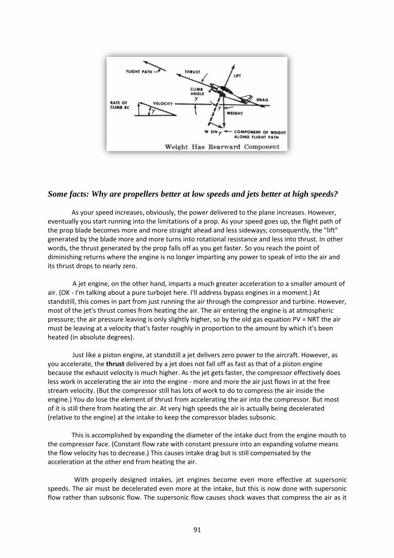
91
Some facts: Why are propellers better at low speeds and jets better at high speeds?
As your speed increases, obviously, the power delivered to the plane increases. However, eventually you start running into the limitations of a prop. As your speed goes up, the flight path of the prop blade becomes more and more straight ahead and less sideways; consequently, the "lift" generated by the blade more and more turns into rotational resistance and less into thrust. In other words, the thrust generated by the prop falls off as you get faster. So you reach the point of diminishing returns where the engine is no longer imparting any power to speak of into the air and its thrust drops to nearly zero. A jet engine, on the other hand, imparts a much greater acceleration to a smaller amount of air. (OK - I'm talking about a pure turbojet here. I'll address bypass engines in a moment.) At standstill, this comes in part from just running the air through the compressor and turbine. However, most of the jet's thrust comes from heating the air. The air entering the engine is at atmospheric pressure; the air pressure leaving is only slightly higher, so by the old gas equation PV = NRT the air must be leaving at a velocity that's faster roughly in proportion to the amount by which it's been heated (in absolute degrees). Just like a piston engine, at standstill a jet delivers zero power to the aircraft. However, as you accelerate, the thrust delivered by a jet does not fall off as fast as that of a piston engine because the exhaust velocity is much higher. As the jet gets faster, the compressor effectively does less work in accelerating the air into the engine - more and more the air just flows in at the free stream velocity. (But the compressor still has lots of work to do to compress the air inside the engine.) You do lose the element of thrust from accelerating the air into the compressor. But most of it is still there from heating the air. At very high speeds the air is actually being decelerated (relative to the engine) at the intake to keep the compressor blades subsonic.
This is accomplished by expanding the diameter of the intake duct from the engine mouth to
the compressor face. (Constant flow rate with constant pressure into an expanding volume means the flow velocity has to decrease.) This causes intake drag but is still compensated by the acceleration at the other end from heating the air. With properly designed intakes, jet engines become even more effective at supersonic speeds. The air must be decelerated even more at the intake, but this is now done with supersonic flow rather than subsonic flow. The supersonic flow causes shock waves that compress the air as it
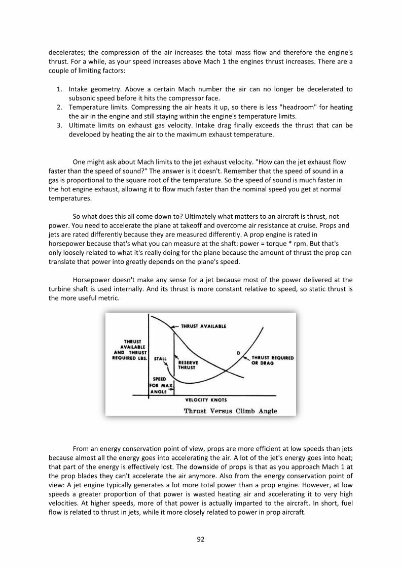
92
decelerates; the compression of the air increases the total mass flow and therefore the engine's thrust. For a while, as your speed increases above Mach 1 the engines thrust increases. There are a couple of limiting factors:
1. Intake geometry. Above a certain Mach number the air can no longer be decelerated to subsonic speed before it hits the compressor face.
2. Temperature limits. Compressing the air heats it up, so there is less "headroom" for heating the air in the engine and still staying within the engine's temperature limits.
3. Ultimate limits on exhaust gas velocity. Intake drag finally exceeds the thrust that can be developed by heating the air to the maximum exhaust temperature.
One might ask about Mach limits to the jet exhaust velocity. "How can the jet exhaust flow
faster than the speed of sound?" The answer is it doesn't. Remember that the speed of sound in a gas is proportional to the square root of the temperature. So the speed of sound is much faster in the hot engine exhaust, allowing it to flow much faster than the nominal speed you get at normal temperatures. So what does this all come down to? Ultimately what matters to an aircraft is thrust, not power. You need to accelerate the plane at takeoff and overcome air resistance at cruise. Props and jets are rated differently because they are measured differently. A prop engine is rated in horsepower because that's what you can measure at the shaft: power = torque * rpm. But that's only loosely related to what it's really doing for the plane because the amount of thrust the prop can translate that power into greatly depends on the plane's speed.
Horsepower doesn't make any sense for a jet because most of the power delivered at the turbine shaft is used internally. And its thrust is more constant relative to speed, so static thrust is the more useful metric.
From an energy conservation point of view, props are more efficient at low speeds than jets because almost all the energy goes into accelerating the air. A lot of the jet's energy goes into heat; that part of the energy is effectively lost. The downside of props is that as you approach Mach 1 at the prop blades they can't accelerate the air anymore. Also from the energy conservation point of view: A jet engine typically generates a lot more total power than a prop engine. However, at low speeds a greater proportion of that power is wasted heating air and accelerating it to very high velocities. At higher speeds, more of that power is actually imparted to the aircraft. In short, fuel flow is related to thrust in jets, while it more closely related to power in prop aircraft.
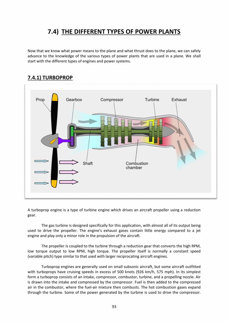
93
7.4) THE DIFFERENT TYPES OF POWER PLANTS
Now that we know what power means to the plane and what thrust does to the plane, we can safely advance to the knowledge of the various types of power plants that are used in a plane. We shall start with the different types of engines and power systems.
7.4.1) TURBOPROP
A turboprop engine is a type of turbine engine which drives an aircraft propeller using a reduction gear.
The gas turbine is designed specifically for this application, with almost all of its output being used to drive the propeller. The engine's exhaust gases contain little energy compared to a jet engine and play only a minor role in the propulsion of the aircraft.
The propeller is coupled to the turbine through a reduction gear that converts the high RPM, low torque output to low RPM, high torque. The propeller itself is normally a constant speed (variable pitch) type similar to that used with larger reciprocating aircraft engines.
Turboprop engines are generally used on small subsonic aircraft, but some aircraft outfitted with turboprops have cruising speeds in excess of 500 knots (926 km/h, 575 mph). In its simplest form a turboprop consists of an intake, compressor, combustor, turbine, and a propelling nozzle. Air is drawn into the intake and compressed by the compressor. Fuel is then added to the compressed air in the combustor, where the fuel-air mixture then combusts. The hot combustion gases expand through the turbine. Some of the power generated by the turbine is used to drive the compressor.

94
The rest is transmitted through the reduction gearing to the propeller. Further expansion of the gases occurs in the propelling nozzle, where the gases exhaust to atmospheric pressure. The propelling nozzle provides a relatively small proportion of the thrust generated by a turboprop.
Turboprops are very efficient at flight speeds below 450 mph (390 knots; 725 km/hr.) because the jet velocity of the propeller (and exhaust) is relatively low. Due to the high price of turboprop engines, they are mostly used where high-performance short-takeoff and landing (STOL) capability and efficiency at modest flight speeds are required. The most common application of turboprop engines in civilian aviation is in small commuter aircraft, where their greater reliability than reciprocating engines offsets their higher initial cost. Turboprop airliners now operate at near the same speed as small turbofan-powered aircraft but burn two-thirds of the fuel per passenger. However, compared to a turbojet (which can fly at high altitude for enhanced speed and fuel consumption) a propeller aircraft has a much lower ceiling.
Propellers are not efficient when the tips reach or exceed supersonic speeds. For this reason, a reduction gearbox is placed in the drive line between the power turbine and the propeller to allow the turbine to operate at its most efficient speed while the propeller operates at its most efficient speed. The gearbox is part of the engine and contains the parts necessary to operate a constant speed propeller. This differs from the turbo shaft engines used in helicopters, where the gearbox is remote from the engine.
7.4.2) MOTORJET
A motor jet is a rudimentary type of jet engine which is sometimes referred to as thermo jet, a term now commonly used to describe a particular and completely unrelated pulsejet design.
At the heart the motor jet is an ordinary piston engine (hence, the term motor), but instead of (or sometimes, as well as) driving a propeller, it drives a compressor. The compressed air is channeled into a combustion chamber, where fuel is injected and ignited. The high temperatures generated by the combustion cause the gases in the chamber to expand and escape at high pressure from the exhaust, creating a thermal reactive force that provides useful thrust.

95
Motor jet engines provide greater thrust than a propeller alone mounted on a piston engine; this has been successfully demonstrated in a number of different aircraft.
7.4.3) THE JET ENGINE or THE TURBO JET
A jet engine is a reaction engine that discharges a fast moving jet which generates thrust by
jet propulsion in accordance with Newton's laws of motion. This broad definition of jet engines includes turbojets, turbofans, rockets, ramjets, and pulse jets. In general, most jet engines are internal combustion engines but non-combusting forms also exist.
In common parlance, the term jet engine loosely refers to an internal combustion air breathing jet engine (a duct engine). These typically consist of an engine with a rotary (rotating) air compressor powered by a turbine, with the leftover power providing thrust via a propelling nozzle. These types of jet engines are primarily used by jet aircraft for long distance travel. Early jet aircraft used turbojet engines which were relatively inefficient for subsonic flight. Modern subsonic jet aircraft usually use high-bypass turbofan engines which offer high speed with fuel efficiency comparable (over long distances) to piston and propeller aero engines.
A turbojet engine is a gas turbine engine that works by compressing air with an inlet and a compressor (axial, centrifugal, or both), mixing fuel with the compressed air, burning the mixture in the combustor, and then passing the hot, high pressure air through a turbine and a nozzle. The compressor is powered by the turbine, which extracts energy from the expanding gas passing through it. The engine converts internal energy in the fuel to kinetic energy in the exhaust, producing thrust. All the air ingested by the inlet is passed through the compressor, combustor, and turbine.

96
7.4.4) PULSE JET
A pulse jet engine (or pulsejet) is a type of jet engine in which combustion occurs in pulses.
Pulsejet engines can be made with few or no moving parts, and are capable of running statically. Pulse jet engines are a lightweight form of jet propulsion, but usually have a poor compression ratio, and hence give a low specific impulse. One notable line of research of pulsejet engines includes the pulse detonation engine which involves repeated detonations in the engine, and which can potentially give high compression and good efficiency. The Figure below explains the working of pulse jets very clearly.
7.4.5) THE RAMJET
A ramjet, sometimes referred to as a stovepipe jet, or an athodyd, is a form of air breathing
jet engine using the engine's forward motion to compress incoming air, without a rotary compressor. Ramjets cannot produce thrust at zero airspeed and thus cannot move an aircraft from a standstill. Ramjets therefore require some other propulsion system to accelerate the vehicle to a

97
speed where the ramjet begins to produce thrust. Ramjets require considerable forward speed to operate well, and as a class work most efficiently at speeds around Mach 3. This type of jet can operate up to speeds of Mach 6.
Ramjets can be particularly useful in applications requiring a small and simple engine for high speed use, such as missiles, while weapon designers are looking to use ramjet technology in artillery shells to give added range: it is anticipated that a 120-mm mortar shell, if assisted by a ramjet, could attain a range of 22 mi (35 km). They have also been used successfully, though not efficiently, as tip jets on helicopter rotors.
7.4.6) SCRAMJETS
A scramjet (supersonic combustion ramjet) is a variant of a ramjet air breathing jet engine in which combustion takes place in supersonic airflow. As in ramjets, a scramjet relies on high vehicle speed to forcefully compress and decelerate the incoming air before combustion (hence ramjet), but whereas a ramjet decelerates the air to subsonic velocities before combustion, airflow in a scramjet is supersonic throughout the entire engine. This allows the scramjet to efficiently operate at extremely high speeds: theoretical projections place the top speed of a scramjet between Mach 12 (9,100 mph; 15,000 km/h) and Mach 24 (18,000 mph; 29,000 km/h). The fastest air-breathing aircraft is a SCRAM jet design, the NASA X-43A which reached Mach 9.8. For comparison, the second fastest air-breathing aircraft, the manned SR-71 Blackbird, has a cruising speed of Mach 3.2 (2,100 mph).

98
7.4.7) TURBOSHAFT
A turboshaft engine is a form of gas turbine which is optimized to produce free turbine (see
graphic at right) shaft power, rather than jet thrust.
In concept, turboshaft engines are very similar to turbojets, with additional turbine
expansion to extract heat energy from the exhaust and convert it into output shaft power. They are even more similar to turboprops, with only minor differences and often a single engine is sold in both forms. Turboshaft engines are commonly used in applications which require a sustained high

99
power output, high reliability, small size, and light weight. These include helicopters, auxiliary power units, boats and ships, tanks, hovercraft, and stationary equipment.
7.4.8) TURBOFAN
The turbofan or fanjet is a type of airbreathing jet engine that is widely used for aircraft
propulsion. The word "turbofan" is a portmanteau of "turbine" and "fan", the turbo portion refers to a gas turbine engine which takes mechanical energy from combustion, and the fan, a ducted fan which uses the mechanical energy from the gas turbine to accelerate air rearwards. The ratio of the mass-flow of air bypassing the engine core compared to the mass-flow of air passing through the core is referred to as the bypass ratio. The engine produces thrust through a combination of these two portions working in concert; engines that use more jet thrust relative to fan thrust are known as low bypass turbofans, while those that have considerably more fan thrust than jet are known as high bypass. Most commercial aviation jet engines in use today are of the high-bypass type, and most modern military fighter engines are low-bypass.
Since most of the air flow through a high-bypass turbofan is low-velocity bypass flow, even when combined with the much higher velocity engine exhaust, the net average exhaust velocity is considerably lower than in a pure turbojet. Engine noise is largely a function of exhaust velocity; therefore turbofan engines are significantly quieter than a pure-jet of the same thrust. Other factors include turbine blade and exhaust outlet geometries, such as noise-reducing "chevrons" seen on the Rolls-Royce Trent 1000 and General Electric GEnx engines used on the Boeing 787.
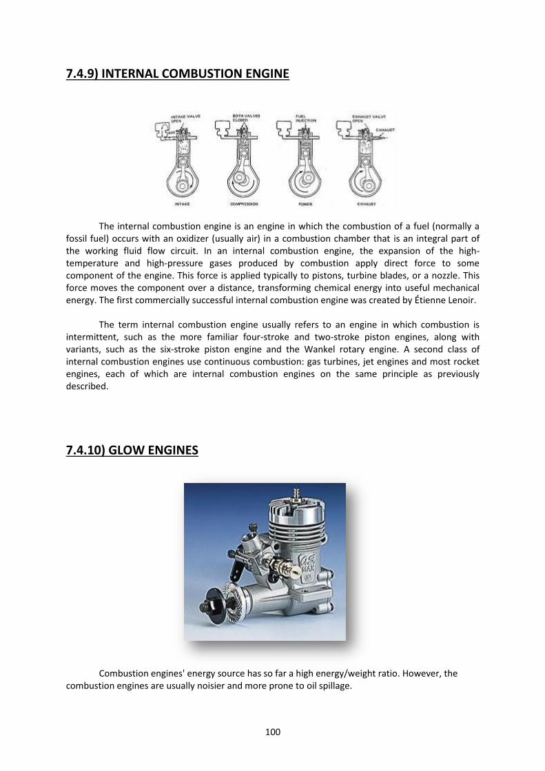
100
7.4.9) INTERNAL COMBUSTION ENGINE
The internal combustion engine is an engine in which the combustion of a fuel (normally a fossil fuel) occurs with an oxidizer (usually air) in a combustion chamber that is an integral part of the working fluid flow circuit. In an internal combustion engine, the expansion of the high-temperature and high-pressure gases produced by combustion apply direct force to some component of the engine. This force is applied typically to pistons, turbine blades, or a nozzle. This force moves the component over a distance, transforming chemical energy into useful mechanical energy. The first commercially successful internal combustion engine was created by Étienne Lenoir.
The term internal combustion engine usually refers to an engine in which combustion is intermittent, such as the more familiar four-stroke and two-stroke piston engines, along with variants, such as the six-stroke piston engine and the Wankel rotary engine. A second class of internal combustion engines use continuous combustion: gas turbines, jet engines and most rocket engines, each of which are internal combustion engines on the same principle as previously described.
7.4.10) GLOW ENGINES
Combustion engines' energy source has so far a high energy/weight ratio. However, the
combustion engines are usually noisier and more prone to oil spillage.

101
There are two types of glow engines: The four-stroke and the two-stroke.
Two-stroke engines are the most used, mainly because they are simple made, light, easy to operate, easy to maintain, and are usually inexpensive. Two-stroke engines operate at a high RPM and therefore can be quite noisy without a good silencer.
Nevertheless, the four-stroke engines also enjoy some popularity, mainly because they produce a lower, more scale-like sound and consume less fuel. They have lower power/weight ratio and lower RPM, but provide more torque (use larger propellers) than theirs two-stroke counter-parts.
However, since the four-stroke engines require high precision engineering and more parts to manufacture, they are usually more expensive. They also need more maintenance and adjustment than the two-stroke, yet they are not too difficult to operate and maintain. A glow engine consists basically of:
Crankcase: This is the main body of the engine and houses the internal parts.
Head: mounted on the top of crankcase. It has fins to provide engine cooling.
Muffler: damps the exhaust noise as it exits the combustion chamber.
Carburetor: to control the amount of fuel and air that enters the engine.
Prop Shaft: is a part of the Crankshaft that protrudes from the crankcase.
The Crankshaft transforms the movements of the Piston into rotational motion.
The Piston has a cylindrical form and operates by an up/down movement (assuming the engine is viewed upright) inside a sleeve, which is called Cylinder. The glow motor's Carburetor consists basically of:
Rotating barrel, which controls the amount of fuel/air mixture going to the combustion chamber.
Throttle arm connected to the barrel, which enables the engine's speed to be controlled by a servo.
Idle Stop Screw to adjust how far the throttle barrel closes.
Idle Mixture Screw to adjust the amount of fuel entering the carburetor while the engine is idling.

102
Needle Valve to adjust the amount of fuel entering the carburetor during medium and high-speed operation.
All glow engines require a special fuel, called "glow fuel." It consists of methanol as base, with some amount of nitro methane to increase the energy and pre-mixed oil into the fuel, which lubricates and protects the engine parts. Two-stroke engines operate by igniting the fuel in its combustion chamber once every turn of its crankshaft. The fuel is mixed with air at the carburetor and forced into the cylinder during the down movement of the piston (1st stroke).
While the piston moves up, the mixture is compressed and when the piston reaches the top, the glow plug ignites the compressed gases, forcing the piston down (2nd stroke). On the way down exhaust gases escape through the exhaust port while the fuel mixture enters the cylinder again. In a four-stroke engine the fuel/air mixture enters the combustion chamber during the down movement of the piston through a valve operated by the camshaft (1st stroke). When the piston moves up, the valve closes and the mixture is compressed (2nd stroke). When the piston reaches the top, the glow plug ignites forcing the piston down (3rd stroke). On the next up movement of the piston, a second valve opens and allows the exhaust gases to escape (4th stroke). The piston moves down and the fuel mixture enters the combustion chamber again, repeating the 1st stroke.
The glow engines usually have a simple ignition system based on a glow plug made up of a little coil of platinum wire rather than a spark plug. A 1.5V battery is used to heat the glow plug only during the starting procedure and is removed when the motor reaches a certain rpm. This is possible because the glow plug keeps glowing by the heat produced during the compression and combustion without needing the battery. There are two lengths of glow plugs available. The short ones are normally used on engines smaller than 2.5cc (.15cu in). Some have a metal bar across the bottom of the plug called for Idle Bar, which prevents raw fuel from dousing the heat from the element during idle.
There are also the so-called "hot" and "cold" glow plugs, which refer to their effective coil operating temperature. The glow plug's temperature depends on several factors, such as the coil's alloy, thickness and length, the size of the hole in which the coil is located as well as which material the glow plug's body is made of.
Usually smaller engines and those that run on less nitro prefer hotter plugs. In case of doubt
just follow the engine manufacturer's recommendation.

103
Turbo glow plugs have a chamfered end that matches the threaded hole on the engine's
head. It is claimed to give less compression leakage around the glow plug and less disruption of the combustion chamber. Also the hole in the cylinder head, which exposes the glow plug to the air/fuel mixture in the cylinder, is much smaller, resulting in fewer rough edges that could create unwanted hot spots. The turbo plug is shown on the picture below.
Glow engines may have plain bushed supported crankshaft or ball bearings. Ball bearing
engines usually have a better performance, run smoother, and last longer but are more expensive than those with bushings.
The model engines' piston and cylinders construction are usually based in two methods: Ringed engines or ABC. Ringed engines have been the main method of construction until recently. It consists of an aluminum or iron piston with a ring moving in an iron sleeve. The ring provides the compression when operating. Ringed engines are inexpensive to restore its compression after long usage by simply replacing a ring, and are generally slightly cheaper. They require an extended break-in period where the motor is run very rich to provide lots of lubrication while the ring fits itself to the cylinder. They are also more easily damaged if the engine is run too lean.
A more recent method is the ABC, which stands for Aluminum, Brass, and Chrome where an aluminum piston runs in a chrome plated brass sleeve. The piston and cylinder are matched at the factory to give a perfect fit and good compression. ABC engines start easily by hand, give more power than the ringed engines, have a good life-span and are less prone to damage with a lean run.
Schnuerle ported engines have several fuel inlet ports on three sides of the cylinder allowing more fuel to flow to the combustion chamber. This gives somewhat more power than with standard porting, which has only one fuel inlet port on the side of the cylinder opposite the exhaust outlet. A Schnuerle ported engine is usually slightly more expensive due to higher manufacturing costs involved.
The fuel tank size and location affects the engine operation during the flight. A typical tank placement is shown on the picture below:

104
When the engine is in the upright position, the fuel tank's centerline should be at the same
level as the needle valve or no lower than 1cm, (3/8in) to insure proper fuel flow. A too large fuel tank may cause the motor to run "lean" during a steep climb and "rich" during a steep dive. Normal tank size for engines between 3.5cc (.21) and 6.5cc (.40) is 150 - 250cc.
CUBIC INCHES = CUBIC CENTIMETERS
.049 CU. IN. = .8 CC
.09 CU. IN. = 1.5 CC
.15 CU. IN. = 2.5 CC
.19 CU. IN. = 3.1 CC
.21 CU. IN. = 3.5 CC
.25 CU. IN. = 4.1 CC
.29 CU. IN. = 4.8 CC
.35 CU. IN. = 5.7 CC
.40 CU. IN. = 6.5 CC
.46 CU. IN. = 7.5 CC
.50 CU. IN. = 8.2 CC
.61 CU. IN = 10.0 CC
.80 CU. IN. = 13.0 CC
.91 CU. IN. = 14.9 CC
1.20 CU. IN. = 20.0 CC
1.50 CU. IN. = 25.0 CC
1.60 CU. IN. = 26.2 CC
1.80 CU. IN. = 30.0 CC
2.00 CU. IN. = 32.8 CC
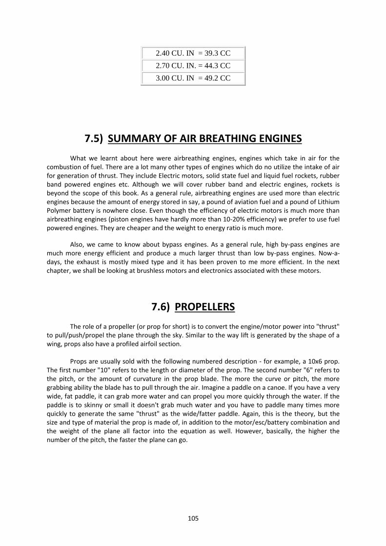
105
2.40 CU. IN = 39.3 CC
2.70 CU. IN. = 44.3 CC
3.00 CU. IN = 49.2 CC
7.5) SUMMARY OF AIR BREATHING ENGINES
What we learnt about here were airbreathing engines, engines which take in air for the combustion of fuel. There are a lot many other types of engines which do no utilize the intake of air for generation of thrust. They include Electric motors, solid state fuel and liquid fuel rockets, rubber band powered engines etc. Although we will cover rubber band and electric engines, rockets is beyond the scope of this book. As a general rule, airbreathing engines are used more than electric engines because the amount of energy stored in say, a pound of aviation fuel and a pound of Lithium Polymer battery is nowhere close. Even though the efficiency of electric motors is much more than airbreathing engines (piston engines have hardly more than 10-20% efficiency) we prefer to use fuel powered engines. They are cheaper and the weight to energy ratio is much more.
Also, we came to know about bypass engines. As a general rule, high by-pass engines are much more energy efficient and produce a much larger thrust than low by-pass engines. Now-a-days, the exhaust is mostly mixed type and it has been proven to me more efficient. In the next chapter, we shall be looking at brushless motors and electronics associated with these motors.
7.6) PROPELLERS
The role of a propeller (or prop for short) is to convert the engine/motor power into "thrust" to pull/push/propel the plane through the sky. Similar to the way lift is generated by the shape of a wing, props also have a profiled airfoil section.
Props are usually sold with the following numbered description - for example, a 10x6 prop. The first number "10" refers to the length or diameter of the prop. The second number "6" refers to the pitch, or the amount of curvature in the prop blade. The more the curve or pitch, the more grabbing ability the blade has to pull through the air. Imagine a paddle on a canoe. If you have a very wide, fat paddle, it can grab more water and can propel you more quickly through the water. If the paddle is to skinny or small it doesn't grab much water and you have to paddle many times more quickly to generate the same "thrust" as the wide/fatter paddle. Again, this is the theory, but the size and type of material the prop is made of, in addition to the motor/esc/battery combination and the weight of the plane all factor into the equation as well. However, basically, the higher the number of the pitch, the faster the plane can go.

106
A larger diameter prop slows the revolutions or reduces the motor's RPM (revolutions per
minute) at any given power setting because there is more prop for the engine to turn over and therefore more work to do. A shorter/smaller diameter prop also makes more noise than a larger prop because it has to spin fast (with less resistance because it is shorter and can turn more quickly with less material for the motor to spin) and in fact you are probably hearing the prop more than the engine on a powerful gas plane with a smaller diameter prop. Usually, prop driven jet planes or higher kV motor driven planes use smaller diameter props that spin many times faster than larger diameter props and therefore sound like a "screamer." Electric gliders on the other hand use longer/bigger diameter props which turn more slowly and are virtually silent in the sky. It all depends on your preference and type of plane.
You could choose a smaller diameter prop on a large glider with a high kV motor, but it would be less efficient and use up more battery energy quicker, be extremely noisy and therefore most people don't use it for this application. If the propeller diameter is too large for a given motor, the motor could overheat and you won't be able to fly long if at all. In the reverse, too small a prop can lead to not enough air displacement and without enough volume of air moving the plane cannot get off the ground.
Do props only have to pull planes forward?
A Pusher Prop is distinct from a "counter rotating prop" - a pusher prop is simply a prop that is reversed on the motor shaft. In other words, normally manufacturers place the size/name markings on the front or forward facing side of the propeller when mounted on the front of an aircraft. However, if using the prop on a "pusher plane" where the prop is mounted in the middle or rear of the aircraft to "push" the plane forward rather than "pull" the plane forward as a front mounted engine and prop does, you must reverse the prop on the shaft so the lettering/name on

107
the prop faces the rear rather than front of the aircraft. Second, you must reverse the spin direction of the motor. To do this, you simply switch any TWO of the three wires from the motor going into the ESC. This reverses the direction of the shaft and thus the prop. There is such a thing as a "pusher prop" sold by some manufacturers which is really a counter rotating prop, but they are simply manufacturing the prop in reverse (and often charge more money because they are rarer to find/sell.) Save the money and simply reverse the prop by flipping it over and inserting the whole of the prop back onto the motor shaft and switch any 2 of the 3 motor to esc wires so the prop now spins the opposite direction. However, if you are flying a dual or twin motor setup on an airplane or a quad copter, you may want to use one regular prop and one counter rotating prop (a pusher prop is not involved in this example.) To determine a pusher prop's direction of airflow (or any other prop), simply stabilize the aircraft so it won't move when the prop is running on the ground and feel which direction the strongest gust of prop "wash" or air dispelled by the spinning prop moves. If it is still weak, try reversing the prop again and see if you sense a difference. If you simply switch the motor to esc wires but don't reverse the prop on the shaft it will not generate much prop wash compared to proper reversing of the prop. Also, reversing the prop and motor to esc wires does not affect the electronics in any negative way nor does it change the amperage or power used by the motor/esc coming from the battery. Also, as discussed earlier, conventional props loose efficiency as the airplane gains speed.
7.7) STYLES OF PROPELLERS
Now, there are different types of propellers. Listed here are a few commercial available propellers in which the style of the prop varies. There are a very large number of designs for propellers and these are a few of the broadest classifications.
1. E props 2. Slow-fly 3. Airscrew 4. Square props
Do go onto the website hobbyking.com and look up the different classification of propellers
based on their styles of construction.
E-props: are the props used for fast flight and are only used on electric models. They are not very heavy so as to reduce load on BLDCs. The max chord length of this type of prop is close to the center of the prop. E.g.: APC 9x5E
SF Props: Slow-fly props are used for slow flight and are usually for slow speeds and have smaller pitches and are less square. They have the max chord length at the center of each blade and are use with low kV or low rpm motors. They can self-destruct at very high rpms and are usually fragile. They have a high volume of air displaced and are more efficient. E.g. 9x4.7 GWS
Airscrew: These props are used mostly in IC engine type of power plants. They are usually very heavy and strong. Their max chord length is also at the center of the prop. E.g. 11x6

108
Square props: These props have the pitch equal to its diameter. They have a capability to go to higher altitudes for the same size of planes. Although they have a higher thrust at a higher airspeed, they have lower thrust at the plane takeoff and the motor has to do more work and it is inefficient at lower airspeeds since a lot of slipping is occurring at low airspeeds. E.g. 7x7 prop In general, less square props give a good acceleration to the plane but can’t go to very high speeds or altitudes. More square props give a bad acceleration but can go to higher speeds and altitudes and are generally suited for pylon racers.
Note on dual pitch propellers These Propellers have dual pitch i.e. they have different pitches at the prop roots and the
tips. Ex 18-6-10 has 18 as the diameter, 6 as the root pitch and 10 as the tip pitch. It is very efficient and has compensation properties i.e. it will bend at the tips and become a prop with a lower pitch at the tips if more load is desired from the prop. At the instance there is an altitude change in a climbing configuration the propeller is giving in to the extra load causing it to flatten out at the highest pitch of the propeller (the tip). With this happening the propeller is literally twisting to the next pitch that will support the load that is developing with the plane climbing, in this case would be the next favorable pitch (like shifting down to a lower gear in your car when you start to climb a hill.
7.8) 3 & 4 BLADED CONVERSION CHART
Given that a propeller has 2 blades, you can generate so much thrust. What
happens if you change the number of blades or the size of blades? The algorithm given
below will give you a rough idea for what to do in case you’re planning on increasing the
number of blades or the size of the blades so that you’re left with the same amount of
thrust.
The conversion for a three and four bladed propeller is a simple tasked if you know
what two bladed propeller you use on a given Engine. For example, on a three bladed propeller you would drop the diameter and keep the pitch. On a four bladed, you would drop the diameter and the pitch. For instance if you had a two bladed 24-10 propeller and you
wanted a three bladed you would use a 22-10 and so on.
Two Bladed Three Bladed Four Bladed
10-6 9-6
11-8 10-8 10-6
12-8 11-8 11-6
12-10 11-10 11-8
109
13-10 12-10 12-8
14-10 13-10 13-8
14-8 13-8 13-6
15-8 14-8 14-6
15-10 14-10 14-8
16-10 15-10 15-8
18-10 16-10 16-8
20-10 18-10 18-8
22-10 20-10 20-8
The performance on a 2 bladed verses a 3 bladed propeller is very little. A - 3 or 4 bladed propeller will give you more thrust, and you will sacrifice a little speed. The big advantage to using a multi blade is that you have more ground clearance less noise factor.
7.9) BALANCING A PROPELLER
A prop needs to be balanced so that there is equal weight on all the blades. If this is not the case then the prop motor will vibrate horrendously and will damage the motor and the motor mount and also the power output will be less. Plus, if you attach any camera to the plane, it will not have a very clear image. It is very important to balance a prop before using it.
To Balance: Place the prop on a balancing jig free to rotate. A balanced propeller should be able to NOT ROTATE when kept in any position on the jig. An unbalanced prop will turn and balance itself only at certain positions. Take a 1” piece of masking tape and place it on the tip of the light blade after mounting it on the balancing jig. Test for balance and add or subtract tape as needed. The amount of masking tape on the blade will tell you how much material you will need to add or remove for final balance. In most cases, the weight of the tape is so slight it won’t show up on a gram scale – say 1” or less of tape. If this is the case, the prop is within spec and can be flown without adding or removing material. https://www.youtube.com/watch?v=OXuNnYQO2s4
To Add Material: For g/f nylon props, place modeling clay or silver solder in the holes in the back of the prop hub, on the side of the light blade, until it balances. For wood props, try adding paint or nail polish to the back of the light blade. Industrial enamel or nail polish can also be used on g/f nylon props.

110
To Remove Material: For g/f nylon and wood props, use sand paper to remove material from the heavy blade and bring into balance. For g/f nylon props, use a pocket knife to trim the edges of the heavy blade. After balancing the propeller, it should be stationary in ANY orientation of the prop when attached on the balancing jig.
7.10) PHENOMENON ASSOCIATED WITH PROPELLERS
7.10.1) Prop wash
A propeller pushes air not just horizontally to the back, but more in a twisting helix around the fuselage (clockwise as seen from the cockpit). As the air whirls around the fuselage it pushes against the left side of the vertical tail (assuming it is located above the propeller's axis), causing the plane to yaw to the left. The prop wash effect is at its greatest when the airflow is flowing more around the fuselage than along it, i.e., at high power and low airspeed, which is the situation when starting the takeoff run.
7.10.2) Propeller torque effect
Torque effect is the influence of engine torque on aircraft movement and control. It is generally exhibited as a left turning tendency in piston single engine propeller driven aircraft. According to Newton's law, "for every action there is an equal and opposite reaction," such that the propeller, if turning clockwise (when viewed from the cockpit), imparts a tendency for the aircraft to rotate counterclockwise. Since most single engine aircraft have propellers rotating clockwise, they rotate to the left, pushing the left wing down. Typically, the pilot is expected to counter this force through the control inputs. To counter the aircraft roll left, the pilot applies right aileron. It is important to understand that torque is a movement about the roll axis. Aileron controls roll. Prop torque is not countered by moving the rudder or by setting rudder trim. It is countered by moving or trimming the aileron. This correction induces adverse yaw, which is corrected by moving or trimming the rudder (right rudder).

111
On aircraft with contra rotating propellers (propellers that rotate in opposite directions) the torques from the two propellers cancels each other out, so that no compensation is needed.
7.10.3) P-Factor
P-factor is the term for asymmetric propeller loading, causes the airplane to yaw to the left when at high angles of attack. The descending right side of the propeller (as seen from the rear) has a higher angle of attack than the upward-moving blade on the left side and provides more thrust. This occurs only when the propeller is not meeting the oncoming airflow head-on, for example when an aircraft is moving down the runway at a nose-high attitude (i.e. at a high angle of attack), as is the case with tail-draggers. Aircraft with tricycle landing gear maintain a level attitude on the takeoff roll run, so there is little P-factor during takeoff roll until lift off. In all cases, though, the effect is weaker than prop wash.
7.10.4) Gyroscopic Effect
Gyroscopic precession is the tendency of a spinning object to precess or move about its axis when disturbed by a force. The engine and propeller act as a big gyroscope. However, gyroscopic precession is likely to be minimal in a typical aircraft. This effect is also not applicable when net angular momentum of the plane is zero. The gyroscopic effect takes place when you apply any control to change the angular momentum of the engine and the propeller, namely yaw and pitch. Gyroscopic precession is also used to great effect by aerobatic pilots to fly lomcevaks and other tumbling type maneuvers. Big prop powered by big engine in light airframe makes for a GREAT demonstration of the phenomena.
7.10.5) Torque Balancing
Torque balancing is a very large factor as far as propellers go. During flight school, you would have noticed that on take-off, the plane yaws in a particular direction and constant correction is required until the plan gains some airspeed. There are four reasons why the aircraft yaws to the left when power was applied for take-off. 1. Torque effect i.e. the engine wants to turn in the opposite direction to the propeller. 2. Asymmetric thrust caused by the lift produced by the down-going blade. 3. Precession caused by the tail coming up, the force being applied at the top of the propeller and taking effect 90 degrees later (clockwise rotating propeller when viewed from the cockpit). 4. Slipstream effect caused by the slipstream of the propeller flowing around the fuselage and striking the vertical fin on the left (similar to a corkscrew). It is for this reason that the fin is offset by two degrees when viewed from the rear. The converse is applied when the power is reduced i.e. nose pitch down and yaw to the right.
112
7.11) CONCLUSION
To sum up the chapter, we learned primarily about the components of a power system and how each component is sub classified into different types. We discussed the nuances of several different types of air breathing engines and how they were classified by their construction and propulsion mechanisms. We also brought into light, different factors and phenomenon surrounding propellers. Following this chapter, we will be dealing with the electronics aboard a plane that help to control and stabilize it during its flight time. We will also be learning about how to select a good set of electronics for your plane keeping in mind the different power, current and voltage requirements of the plane.

113
CHAPTER 8
AVIONICS

114
8.1) INTRODUCTION
The following chapter will deal with the electronic systems that are on board an aircraft. The electronics that are onboard a plane generally takes care of the control and stability of the plane while in flight. In case of electric fliers, the propulsion systems are also electronic. (BLDC motors). In general, the avionics on a plane have different components which are each covered in detail in this following chapter.
1. Battery packs. 2. Electronic Brushless DC motor 3. Electronic Speed Controller (ESC) 4. Servos 5. Gyros 6. Flight controllers for multirotors
The following chapter will deal with the structure, function and specific ratings of each
component and will compile, in the end, how to calculate the ratings of each components for a given plane’s weight and its aerodynamic capabilities.

115
8.2) BATTERY PACKS
Structure: It is a cuboid shaped pack with several plate-like cells inside. You will notice 2 sets of wire – one black-red pair for supplying voltage to the ESC. One multicolored-wire pin for putting into the charger. The number of wires on this will depend on the S-rating of the battery pack.
Function: To supply electrical power to the systems aboard the plane.
Types:
1. NiMH (Nickel Metal Hydride - stable, toxic, less energy storage and heavy compared to Lipo) Single cell is equal to 1.1V
2. NiCad (Nickel Cadmium - stable, toxic, more energy storage than NiMH but less than Lipo
and heavy compared to Lipo) Single cell is equal 1.2V
3. LiPo Cell (Lithium Polymer - more prone to being flammable if punctured or over-taxed, very light, twice the energy storage) Single cell is equal to 3.7V
5-7 cells NiMH/NiCad (6v - 8.4v) = 2 cells Lipo (7.4 volts)
8-10 cells NiMH/NiCad (9.6v - 12v) = 3 cells Lipo (11.1 volts) 11-13 cells NiMH/NiCad (13.2v - 15.6) = 4cells Lipo (14.8 volts) 14-16 cells NiMH/NiCad (16.8v - 19.2v) = 5 cells Lipo (18.5 volts)
Fig: A standard issue lithium polymer battery
8.2.1) Ratings involved

116
Capacity (mAH):
This is usually the biggest number shown on the pack and is measured in mAH
(Milliamp/hour) or Ah (Amp/hour). It shows the value of continuous current at which the battery will deplete within an hour of operation. The capacity is the first indicator of the batteries size. To keep things simple, think of capacity (mAH) as the amount of fuel in your cars gas tank. A higher capacity tank will run your car for longer. A 4,000mAh battery will run for twice as long as a 2,000mAh battery. A 2,000mah battery will (in theory) run for 1hr if drained at a constant 2,000 Milliamps or 2A.
Discharge (C-rating):
Discharge is the amount of power the battery can 'push'. The number shown ('20C') is a
multiplication of the capacity. For example; A 20C battery can discharge at 20 x 2,000mAh which is 40,000mAh or 40Amps. This is an important number if you know your motor requires a certain power level. In addition to this, batteries have a 'Burst' rate, which is the amount of power the battery can discharge for a short period, usually 10-20 seconds. A typical battery label may show 20-30C and 1000mAh. This would mean a 1,000mAh battery can discharge 20,000mAh constantly or give a sudden and short 10-20 second 30,000mAh (30A) burst of power.
Tip: A higher 'C' rated battery will last longer if run at a lower 'C' rate. Example: a 30C battery run at 20C maximum will have a longer cycle life than a 20C run at 20C each flight. The extent to which a battery is discharged affects its life.
So, given the discharge rating and the mAh rating, how do you calculate the lifetime and current draw of the battery?
1. Take the C rating and put it in the formula
I = C*mAh/1000 Amps
This will give a value of current that can be drawn continuously from the battery safely. Note that if there are TWO C ratings, the lower one signifies the continuous current and the higher one signifies the burst current discharge rate. In the example given above, we calculated from this formula that the battery can supply 40 A safely. If it had the C-rating as 20-30 C, the value corresponding to 30C would correspond to 60 A. This value of current is the current that the battery can supply in a burst of about 5 to 10 seconds before permanent damage occurs.
2. Now that you have this value of current, we know from the mAh rating that how much
current the battery can supply continuously for one hour. And hence, we can calculate the amount of charge in the battery through the formula Q = 3600*mAh/1000.
3. This same amount of charge can be discharged at any possible rate within the limits of the battery. Hence, to calculate the amount of time that the battery will last at a particular discharge rate C, simply plug in the value into the following linear relation:
3600 * mAh/1000 = C*mAh*t/1000
4. This simply boils down to saying that:
If you would like to find the amount of time that a discharge at a particular C rating would last, simply divide 60 by C to obtain the amount of time in minutes.

117
Eg. How about a 20C rating on a 2000 mAh battery? 20 x 2000 = 40,000 milliamps or 40 amps. Time wise, a 40 amp draw on this pack would exhaust it in about 3 minutes
Voltage (S):
All Lithium Polymer cells in any industry have a nominal voltage of 3.7v per cell. When fully
charged a Li-poly cell should be 4.2v and when discharged it should never be below 3v. You will notice that Li-poly RC packs are made up of layers of multiple cells. If the battery's rating is 3S, it means it is 3 x 3.7v which is 11.1v. It has 3 layers of 3.7v each. In other words, it’s a '3 cell pack'.
Some batteries designate their S-ratings as xSyP. X indicated the number of cells connected in series to form a battery. Y indicated the number of such batteries connected in parallel. This parallel connection between multiple batteries is done so that a constant voltage can be maintained across the two terminals but the current rating can be increased linearly with the number of parallel connections. In our tricopter, we use a parallel harness to use two batteries in parallel. Internal Resistance: Internal resistance is not a rating or specified on a battery, but it is important to understand it. A 3s battery which promisingly delivers 11.1V promisingly, is actually delivering a little more (around 12.6V). This extra voltage is used against the internal resistance of the battery. The LiPo being a electrochemical cell, has a definite value of internal resistance.
Weight/Size:
For a battery to be right for your model it must fit within the models battery compartment
and also balance the plane correctly. It's tempting to choose the biggest and most powerful battery your model can handle, but this will sacrifice flight performance and if your packs voltage is too high; destroy the ESC or Motor. Check with your ESC and Motor specification to ensure you have the right voltage pack then check the models CG (Center of Gravity) to decide on the right battery weight.
Fig: A standard Li-poly ratings chart from hobbyking.com

118
Li-poly Voltage Choice:
Based on the above, we now need to work out what voltage we are going to need to use.
Generally, to keep LiPos in good order, you should try and keep max amperage to around 50~60% of the capacity/C rating (we will come to that later) of the Li-poly Pack.
For example, if you purchase a 2200mAh 20c pack, then it is rated for 44A constant discharge, so keep the max amps at around 20A~25A if possible. 44A is the burst current which is used only at times when there is sudden increase in throttle to 100%. Keeping max discharge at 20-25A allows for bursts of current in case of emergencies. Choose the capacity of pack based on recommendation for the model by model manufacturer and in conjunction with the size/weight data published with the Li-poly packs. For low powered models, choose 20c packs, 20 to 25C for general flying and 30C+ packs for high performance planes. Up to 50w : 1s~2s Up to 100w : 2s~3s 100w Up to 500w : 3s (Practical upper limit for 3s LiPos, so basically, models of 5lb
AUW) 500w up to 800w : 4s (This is the 0.40~0.46 glow equivalent range favored by many club flyers) 800w up to 1000w : 5s 900w up to 1500w : 6s (this is the 0.60~0.90 IC equivalent range)
8s~10s packs are for very large and generally specialized models. It can sometimes be difficult to know which battery is best for your application. For R/C aircraft there is a huge variety of batteries available and while many may suit your application your ultimate goal is to purchase a battery pack that will; -Be within your budget -Have a long cycle life -Have the correct size and weight -Give you the longest flight times -Be able to deliver the correct voltage/amp (Power) Let’s hope this simple guide helps you understand the different types of Lipoly (Lithium Polymer) batteries and which is right for your model. You may have noticed by now that batteries have different ratings, sizes, plugs, wire, charge rates and chemical makeup. Let’s decipher;
8.2.2) Charging
1. Always use a lithium Polymer battery charger and never charge the battery above 4.2v
per cell. (Example: 2S, never above 8.4v) 2. Never leave a charging battery unattended for hours. 3. Never allow the battery's voltage to fall below 3v per cell. (Example: 3S, never below 9v).
Note: A cell balancer is connected to the LiPo battery to charge it and to get the voltages of every cell to a similar value. In case the cells of a LiPo are not balanced, then the battery life will degrade and your battery will either puff out or have reduced capacity. This happens because the cells will

119
get unevenly discharged and the esc won’t be able to judge properly the cut-off voltage because it might be deceptive.
8.2.3) Lasting Power/Time of Batteries
To work out how long a fully charged battery will last, let's use: 1500mAh 20C 11.1v (3s) Simply divide the minutes in one hour by the C rating 60 minutes (1 hour) divided by the C rating = max discharge run-time 60 minutes / 20c = 3 minutes Table of common C ratings and flat out run time 30C (45A) = 2 minutes 25C (37.5A) = 2.4 minutes 20C (30A) = 3 minutes 15C (22.5A) = 4 minutes 10C (15A) = 6 minutes 5C (7.5A) = 12 minutes 1C (1.5A) = 60 minutes, naturally.
Care of your LiPo battery
Always take good care of your LiPos, firstly because they are like small bombs if not taken care of properly and because they are expensive.
Always examine a LiPo before use. Check for puffing or cuts on the body because the LiPos usually don’t come in a hard case pack.
In case a puff/dent/cut/leakage is detected, do not use the battery or touch the film inside. Using a damaged battery may result in a fire or explosion with poisonous flames.
Never leave the battery to charge unattended.
Never exceed the discharge rate. NEVER let the cell voltage fall below 2.7 volts. If this happens the battery will never be able to get charged again. Modern ESCs have an automatic cutoff system, where the battery is just cut off once it falls below a pre-determined safe limit. GGWP.
If you are testing a battery pack for the first time, do not run the battery for more than 1-2 minutes. After 1-2 minutes get the plane back on the ground and check if the battery has become too hot or not. If yes, get a better, bigger battery for the plane.
When installing on a plane, make sure you do not squeeze it into the fuse or install it close to sharp corners or metal nuts/bolts. Failure to do this might cause the plane burning up mid-flight or the battery getting totally damaged beyond repair.
Buy a LiPo charging bag if you want to leave the battery charging unattended. Most of the times the cause of LiPo fires is faulty chargers and not the battery packs themselves.
Do not use any metal object to pry off the connectors to the ESC (XT-60 or DEAN plugs (T plugs)). You might accidentally short the battery. Always use insulated objects to disconnect battery.

120
In case of any shorts, if the battery starts to get warm or if there is sparking or smoke rising, immediately throw the battery in an open space and stand at least 10 metres away from it. Do NOT take this casually. Lithium is extremely reactive and dangerous to both the human body and its soul.
Ask a senior before connecting the battery to any charger etc. in case you are even slightly unsure of what you are doing.
Never connect the battery to the ESC without switching on the RC.
8.3) MOTORS
Motors have become a very intricate part of our day to day lives. They power the wheels of our toy cars, our fans, our mixers and grinders and most importantly, our RC planes. Motors work using a deceptively simple mechanism. The main use of a motor is to generate a rotational torque which can then be turned into translational energy. In particular, we will be dealing with Brushless DC Motors.
Structure: A motor consist of 2 main parts which will be discussed in detail presently – the stator and the rotor.
Stator: This part of the motor is, as the name suggests, the stationery part of the motor. It consists of several electromagnetic bars made of soft iron around which wires are coiled. They are placed in a radially symmetrical manner. The number of such soft iron magnets is always a multiple of 3. As to why will be explained in a moment.
Rotor: This part of the motor is the part that rotates. It consists of a set of permanent magnets that are attached in a radially symmetric manner. They can be inward or outward facing depending on the stator. As you will see in a minute, motors are classified on this basis.

121
Fig: Note how the rotor fits into the stator assembly. This is an example of an inrunner motor.
Function: Motors function with the help of an electrical gadget known as an electronic speed controller. What this speed controller does it to take a DC voltage and convert into a 3-phase AC source. What does this mean? Remember how the magnets on a stator are supposed to be in multiples of 3? The 3 wires coming from the ESC each deliver a separate AC voltage each at a phase difference of 120 degrees, thus leading to a total of 360 degrees. One wire from the ESC contains several smaller wires which are all connected in parallel and wrap around every third magnet. So how does this help? For a given magnet on the rotor, consider the 3 stator magnets closest to it. One magnet is going to be repelling it. The one in between is going to have a minimal effect on it. The one on the other side is going to be attracting it. Hence, the given rotor magnet will move in that particular direction. Since the rotor magnets have polarities such that this happens around the entire 360 degrees of the motor simultaneously, torque is generated and an RPM occurs. As the rotor magnet moves onto the next set of 3 magnets, the 120 degrees phase change with each source will ensure that the polarities of the previous 3 magnets will be transferred to the next 3 magnets and hence, the cycle repeats itself. By changing the rate at which the field is varied, the ESC can control the RPM of the motor.
Types: Depending on which part of the motor is on the inside and on the outside, BLDC motors are classified into 2 main types: Outrunners and Inrunners.
If the rotor is on the outside and the stator is on the inside, as indicated in the first diagram, the motor is an Outrunner. If it’s the other way around, it’s an inrunner. (Indicated in the second diagram) So what’s the difference between the two? Since the rotor of the outrunner has a larger radius, it delivers a much higher torque than an inrunner. However, since the rotor of the outrunner is equally big, it is difficult to swing around and hence, the top RPMs are lower when compared to an inrunner. An inrunner, on the other hand, has RPMs so high that it is impossible to mount a propeller on it without the use of a gear box.

122
8.3.1) Indicated Ratings
Kilo Volt Rating:
kV is a number that relates to how many RPMs a given motor will spin based on applied voltage. You will see specs on motors where it says kV=860. That means that the motor will spin at 860 RPM if you apply one volt to it. If you apply 7 volts it will span at 6020 RPM. If the manufacturer takes the same motor, he can wind it so that it will have a lower KV rating, which typically produces more torque.
A manufacturer can wind a motor in such a way that it has a low KV rating. This means that it
can deliver more torque and hence, can be used to swing big propellers. This is critical in aircraft such as gliders where power is much more important than top speed.
Take the same motor and wind it differently and it will have a higher KV rating producing
higher speeds for a given voltage. These are typically used with smaller props for higher top speeds. Or they can be used with gear boxes to handle those big props, providing a similar result to low KV motors. Sometimes a gear box works better in the installation.
You would also take KV into consideration based on what battery you plan to use. If you look here you will see that a given motor is offered in several KV ratings. The website makes suggestions as to which motor is best matched with which prop and which battery packs. If you click on a given motor you can see what kinds of power are drawn based on which pack and which prop. If you click on each of the motors within a model you can see the very different power curves produced by the different battery/prop combos. Here you see the same motor with a different wind producing a different KV result, each optimized for a different purpose.
Max Current: This rating is pretty obvious from the name. It is the current that the motor draws at the maximum indicated wattage at a given voltage. It is very important that the ESC and battery combination must be able to supply atleast 1.5 times this rating in case the motor need to exert itself beyond its capabilities and for overall electronics safety in general.
Max Power: This rating indicates the maximum power at which it is safe to run the motor. Running the motor beyond this might cause the motor to burn out or damage the ESC/battery in the process. It is indicated on the motor by the manufacturer and is determined from tests. Note: The maximum power (P) and the maximum current draw (I) are related by the following equation at a particular voltage (V)
P = I x V x 0.8 Where 0.8 is the power factor from the phase difference between the 3- phase source.
Cell rating:

123
This is a rating of the voltage that the motor needs to be supplied. Depending on the current and power draws, a cell rating is specified along with the motor. This cell rating (S) is the S-rating of the battery that needs to be connected to the ESC.
Fig: A motor’s rating chart form hobbyking.com
8.4) ELECTRONIC SPEED CONTROLLERS (ESC)
As mentioned previously, the job of the ESC is to control the speed or RPM with which the motor rotates. It also supplies the power to the motor.
Structure: An ESC is a small, rubber covered circuit board on which several capacitors, resistors, ICs are mounted. It consists of 3 sets of wires. The first is a black-red wire that connects with the battery. The second is a cable with 3 conjoined wires that connects to the receiver. And the third set is a set of 3 wires (generally black) that connects to the 3 wires coming from the motor.

124
Fig: A simple ESC. Note the Red-Black wires, the Red-Black-White wire with a receiver pin at the end
and the 3 blue wires that are to be connected to the motor.
Function: You must have noticed by now that the ESC takes an input in the form of 2 wires but transmits it as 3 wires. What is the significance of this? It is that the ESC accepts a constant DC voltage from the battery and with the help of complex internal circuitry, converts this to a 3-phase AC signal for the motor. By varying the frequency of these AC signals, the ESC controls the motors RPM level.
8.4.1) Indicated Ratings:
Current rating:
This figure gives you the maximum current that can be safely supplied by an ESC. You have decided on your motor, so look at the MAX AMPS figure given by the motor manufacturer in the data section and generally add 25-50% headroom. So, if a motor is rated to 15A, then choose at least an 20A ESC, better still a 25A and so on. The small additional weight on a larger esc (5-10grams on average) is so small it really won't make a difference in your flight and you will keep your electronics working a lot longer because they are staying cooler and not being overtaxed.
Voltage rating:
Next make sure that the ESC voltage is compatible, in other words, if you are using a 4s Lipo, that the ESC is rated for 4s voltage. Next, check if it has functions you desire, if you are flying a glider for instance, you will want a brake facility so that the prop stops when soaring un-powered, allowing the prop to fold by not wind milling, we strongly advise purchasing a programmer card to make programming the ESC easier.

125
Fig : A ESC programming card
BEC rating (Battery Elminiator Circuit):
This circuit in your ESC allows the receiver (and servos) and the motor to run from the same battery. This saves the weight of second battery. Most modern ESCs have this BEC feature. Be careful to read the manufacturers specs, as BECs have limitations on number of battery cells and servos that can be safely used.
LVC rating (Low Voltage Cut-off):
In a system using BEC, the power to the motor is cut off when the battery voltage drops below a certain value. Power to the receiver is maintained, enough to allow several minutes of control. The airplane is glided to a safe landing with the radio fully functional.
Also look at BEC rating, the BEC supplies radio receiver power for servo's without the need for a separate receiver battery, however, the can be limited in the number of servo's they are capable of powering, if the servo count is over 4, as it is on many models these days, then consider purchasing an ESC with a high AMP rated SBEC, or a separate UBEC, OPTO type ESC's (they have no BEC, keeping the ESC separate from RX supply) are recommended for large models that require a separate receiver power supply, they are also safer in high powered, large models as they will not arm until the RX is switched on. UBEC-universal battery eliminator circuit SBEC-serial battery eliminator circuit These circuits directly connect a battery pack to the receiver. They are not coupled with ESC and are independent and they are used for IC engine planes and sailboats etc.

126
Fig: a set of ESC specifications from hobbyking.com
ESC Programming:
Several parameters can be programmed on your ESC for various different performance characteristics.
A number of the performance parameters for the ESC are set as default values. By using a Program Card (available separately) or a transmitter these default values can be set to meet the users’ particular performance requirements. The following will deal with these factors
E.1 Brake Type: There are three brake types including OFF (brake disable), Soft brake and Hard brake. The default is OFF (brake disable). Soft brake: less forceful and lasts longer. Hard brake: more forceful and lasts a shorter time.
E.2 Timing Mode: There are three options: Low, Mid and High. The default is Mid. Low advance timing is recommended for high inductance and low KV motors. High advance timing is recommended for low inductance and high KV motors, e.g. high KV out runner motors. For some high KV motors, if it shakes while rotating in high speed, the High timing mode is recommended.
E.3 Cutoff Mode: There are two options: Soft-Cut and Cut-Off. The default is Soft-Cut. Cut-Off option: immediate motor shutdown occurs in low-voltage. Soft-Cut option: Gradually reduce throttle power to 50% of the current power at low-voltage. E.4 Start Mode: There are three options: Fast start, Soft start and very Soft start. The default is Fast start. Fast start is recommended for low inductance and low start loading motors. Very Soft start is recommended for high inductance and high start loading motors. Soft start is recommended for those motors with medium inductance and medium start loading.
E.5 Throttle Curve Mode: Three options: Normal, Soft (Governor-Low), AND Super-Soft (Governor-High) Normal is preferred for fixed-wing aircraft. Soft or Super-soft are preferred for helicopters. The initial acceleration of the Soft and Super-Soft modes are slower in comparison,

127
usually taking 1 second for Soft startup or 2 seconds for Super-Soft startup from initial throttle advance to full throttle. If the throttle is closed (throttle stick moved to bottom) and opened again (throttle stick moved to top) within 3 seconds of the initial startup, the restart-up will be temporarily changed to normal mode to get rid of the chances of a crash caused by slow throttle response. This special design is very suitable for aerobatic flight when quick throttle response is needed.
E.6 Li-XX Cells: It is used to choose cells of Li-xx battery packs. Range: 0-12 cells. The default is 0 cells. If the battery cell is 0, the system will automatically identify the battery cell as 0 and calculate the Low-voltage cutoff voltage. E.g. suppose the low-voltage cutoff voltage is 2.85V per cell (under Mid Low-voltage cutoff type), if there’re 3 cells, the total Low-voltage cutoff voltage would be 2.85*3=8.55V.
E.7 Cutoff voltage: There’re three options: Low, Middle, and High. The default is Middle. Low: Low-voltage cutoff voltage is 2.6V per cell. Middle: Low-voltage cutoff voltage is 2.85V per cell. High: Low-voltage cutoff voltage is 3.1V per cell.
E.8 Motor Rotation: Options: Normal and Reverse. The default is Normal.
8.5) SERVOS
Servos are small electronic components that help to move the control surfaces of your
airplane. They generally are very small but supply a vast amount of torque despite their size through
a system of gears. They transmit this torque through rods and hence, move the control surfaces.
Structure:
Small cuboid shaped structures. In case they are transparent enough, you will be able to see
the gears and shafts inside them. They have a small head onto which fits a plastic arm and a screw to
keep the arm in place. They have a set of 3-wire cables where one is light in colour and the other are
either red-black or red-brown, etc. This connects to the receiver and draws power from the ESC via
the receiver.
Function:
They help to move control surfaces. They do this with the help of arms and push rods. The
servo gear is connected to an arm like structure with holes. A rod is run through this hole and then is
connected to the control surface with a similar device called a horn. As the servo arm rotates
through some number of degrees, that movement is translated into linear movement by the push
rod and then, is used to move the control surface

128
Fig: A servo motor with the push rod, hexagonal servo arm and the mounting screw clearly visible.
Indicated Ratings:
Torque: This is a rating of how much torque the servo is able to deliver. It is rated as the number of
KGs a servo is able to pull at a distance of one cm from its rotational gear at a given voltage.
Speed: This is a rating of the speed of the servo. It is given by the time that the servo takes (in sec)
to move an angular distance of 60 degrees at a given voltage. For example, 0.09/60 deg @ 4.8V.
Weight: The weight in grams of the servo.
Fig: A Servo specifications table from hobbyking.com
IMPORTANT: Never move the arm of a plastic or resin gear servo manually. It has small gears which
may break, making the entire ESC useless.
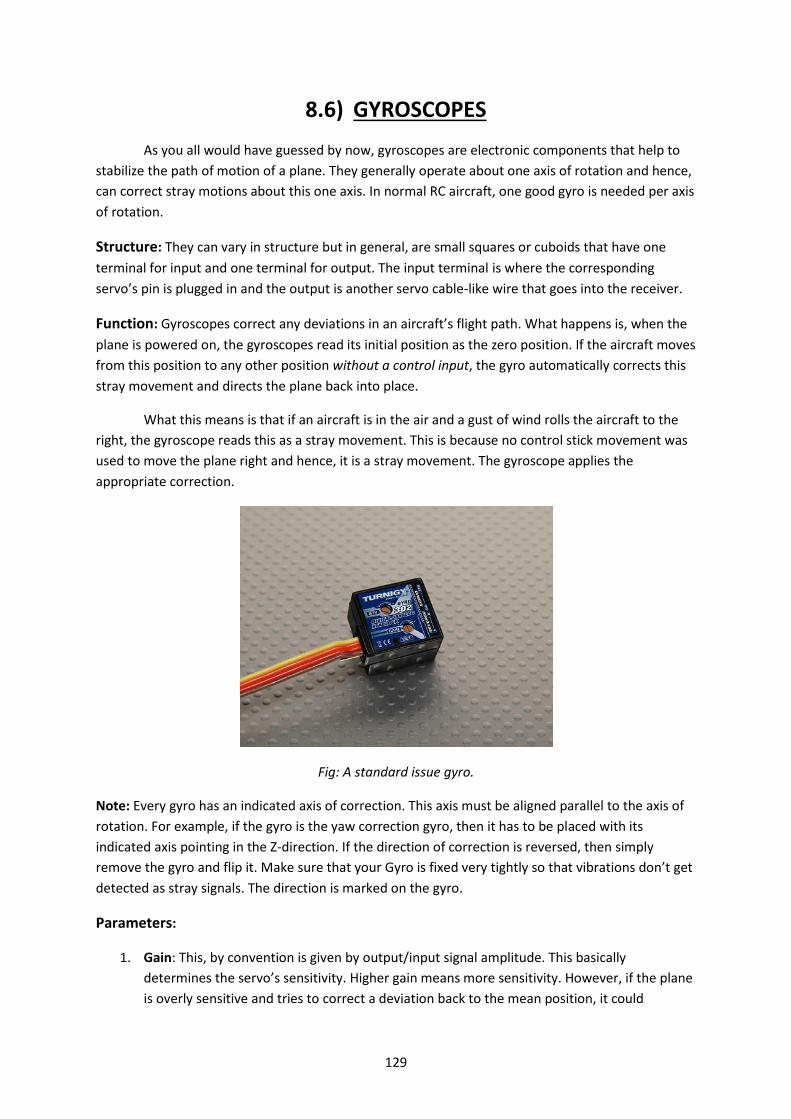
129
8.6) GYROSCOPES
As you all would have guessed by now, gyroscopes are electronic components that help to
stabilize the path of motion of a plane. They generally operate about one axis of rotation and hence,
can correct stray motions about this one axis. In normal RC aircraft, one good gyro is needed per axis
of rotation.
Structure: They can vary in structure but in general, are small squares or cuboids that have one
terminal for input and one terminal for output. The input terminal is where the corresponding
servo’s pin is plugged in and the output is another servo cable-like wire that goes into the receiver.
Function: Gyroscopes correct any deviations in an aircraft’s flight path. What happens is, when the
plane is powered on, the gyroscopes read its initial position as the zero position. If the aircraft moves
from this position to any other position without a control input, the gyro automatically corrects this
stray movement and directs the plane back into place.
What this means is that if an aircraft is in the air and a gust of wind rolls the aircraft to the
right, the gyroscope reads this as a stray movement. This is because no control stick movement was
used to move the plane right and hence, it is a stray movement. The gyroscope applies the
appropriate correction.
Fig: A standard issue gyro.
Note: Every gyro has an indicated axis of correction. This axis must be aligned parallel to the axis of
rotation. For example, if the gyro is the yaw correction gyro, then it has to be placed with its
indicated axis pointing in the Z-direction. If the direction of correction is reversed, then simply
remove the gyro and flip it. Make sure that your Gyro is fixed very tightly so that vibrations don’t get
detected as stray signals. The direction is marked on the gyro.
Parameters:
1. Gain: This, by convention is given by output/input signal amplitude. This basically
determines the servo’s sensitivity. Higher gain means more sensitivity. However, if the plane
is overly sensitive and tries to correct a deviation back to the mean position, it could

130
overshoot and send the plane into the opposite direction. This will cascade back and forth
until the plane is uncontrollable. Carefully set gyro gain.
2. Operation temperature
3. Current Draw: This represents the amount of current that the gyro draws.
8.7) FLIGHT CONTROL BOARD
Flight control boards are the most important parts of any multirotor. They make the most
complicated mechanisms available simply to use. A flight control board translates the RC stick
movements into actual movements on the copter. It also employs electronic circuit and loop
mechanisms to provide automatic stability to the copter.
Structure: Flight control board is a square piece of very complicated electronic circuitry. It has very
small ICs, resistances, gyroscopes and sometimes accelerometers and gyroscopes. It either has a USB
port connected to a memory storing capable IC or an interactive touch screen that can be used to
change feed, gain, orientation values.
Proportional-Integral-Derivative:
When the multirotor orientation is changed in any pitch/roll/yaw axis, the gyros indicate an angular
change from its initial position. The MultiRotor controller records the original position and by
utilising a "PID" program loop, drives the motors to attempts to return the MultiRotor to its initial
position.
This is done by a combination of the measured angular deviation, sampling the change over time
and predicting the future position. This provides enough information for the controller to drive the
motors to return equilibrium.
Basic PID Tuning:
1. Set PID to the designers default recommended settings
2. Hold the MulitiRotor securely and safely in the air
3. Increase throttle to the hover point where it starts to feel light
4. Try to lean the MultiRotor down onto each motor axis
5. You should feel a reaction against your pressure for each axis.
6. Change P until it is difficult to move against the reaction. Without stabilization you will feel it
allow you to move over a period of time. That is OK
7. Now try rocking the MultiRotor. Increase P until it starts to oscillate and then reduce a
touch.
8. Repeat for Yaw Axis.
Advanced Tuning - understanding impact of P, I and D
P (proportional) - this is the amount of corrective force applied to return the MultiRotor back to its
initial position. The amount of force is proportional to a combination of the deviation from initial
position minus any command to change direction from the controller input.
A higher P value will create a stronger force to resist any attempts to change its position. If the P
value is too high, on the return to initial position, it will overshoot and then opposite force is needed

131
to compensate. This creates an oscillating effect until stability is eventually reached or in severe
cases becomes completely destabilized.
Increasing value for P:
It will become more solid/stable until P is too high where it starts to oscillate and lose control. You
will notice a very strong resistive force to any attempts to move the MultiRotor
Decreasing value for P:
It will start to drift in control until P is too low when it becomes very unstable. Will be less resistive
to any attempts to change orientation
IMPORTANT:
Aerobatic flight: Requires a slightly higher P
Gentle smooth flight: requires a slightly lower P
I (integral) - this is the time period for which the angular change is sampled and averaged. The
amount of force applied to return to initial position gets is increased the longer the deviation exists
until a maximum force value is reached. A higher I will increase the heading hold capability
Increasing value for I:
Increase the ability to hold overall initial position and reduce drift, but also increase the delay in
returning to initial position. Will also decrease the importance of P.
Decreasing value for I:
Will improve reaction to changes, but increase drift and reduce ability to hold position. Will also
increase the importance of P.
IMPORTANT:
Aerobatic flight: Requires a slightly lower I
Gentle smooth flight: Requires a slightly higher I
D (derivative) - this is the speed at which the MultiRotor is returned to its original position. A higher
D (as it is negative value this means a lower number - i.e. closer to zero) will mean the MultiRotor wil
snap back to its initial position very quickly
Increasing value for D: (remember, that means a LOWER number as it is a negative value) Improves
the speed at which deviations are recovered. With fast recovery speed comes a higher probability of
overshooting and oscillations. Will also increase the effect of P
Decreasing value for D: (remember, that means a HIGHER number as it is a negative value - i.e.
further from zero) Reduces the oscillations when returning any deviations to their initial position.
Recovery to initial position becomes slower. Will also decrease the effect of P.

132
Aerobatic flight: Increase D (remember, that means a LOWER number as it is a negative value - i.e.
closer to zero)
Gentle smooth flight: Decrease D (remember, that means a HIGHER number as it is a negative value
- i.e. further from zero)
ADVANCED TUNING – has to be done intuitively..
For Aerobatic flying:
Increase value for P until oscillations start, then back of slightly. Change value for I until hover drift is
unacceptable, then increase slightly. Increase value for D (remember, that means a LOWER number
as it is a negative value - i.e. closer to zero) until recovery from dramatic control changes results in
unacceptable recovery oscillations. P may now have to be reduced slightly as increasing D increases
effect of P.
For stable flying (RC):
Increase value for P until oscillations start, then back of slightly. Change value for I until recovery
from deviations is unacceptable, then increase slightly. Decrease value for D (remember, that means
a HIGHER number as it is a negative value - i.e. further from zero) until recovery from dramatic
control changes becomes too slow. Then Increase D slightly (remember - lower number!). P may
now have to be reduced slightly.
8.8) CONCLUSION - PUTTING IT ALL TOGETHER
Now, you officially know all about the avionics onboard a plane. So, given a plane’s weight
and performance capabilities, you can pick a well-functioning set of electronics for the plane. Make
sure you obey the Watts per Pound rule to decide your motor’s power rating. This will be your
starting point.
Less than 50W/lb - Very lightweight / low wing loading slow flyer. 50 to 80 W/lb - Powered gliders, basic park flyers and trainers, classic biplanes. 80 to 120 W/lb - General sport flying and basic/intermediate aerobatics. 120 to 180W/lb - More serious aerobatics, pattern flying, 3D and scale EDF jets 180 to 200+W/lb - Faster jets and anything that requires massive amounts of muscle!
The following set of steps is followed for finding a set of electronics for the plane.
1. Take a rough number for the All-Up Weight (AUW) of your plane depending on estimates,
permitted weight, etc. It should include both the plane and an appropriate allowance for
electronics.
2. Next, take a look at your flight capabilities required. Once flight capability has been
assessed, calculate the required wattage of the motor by multiplying the watts per pound
rating with the AUW in pounds.

133
3. The motor is your best place to start as it generally has the largest number of suggested
ratings for your other devices.
4. Take a look at the maximum current draw, the S-rating and the recommended propeller
rating of the motor. This is often the best place to start to look for your required ESC and
propeller.
5. The ESC’s current rating should be around 1.5 times that of the maximum current rating of
the motor. This is just to ensure that the ESC is able to supply current to the motor no
matter how stressfully the motor is running. This will also leave enough extra current to
power any attached servos.
6. Note that the ESC will have 2 specific ratings to look at – The sustained/burst current and the
S-rating of the ESC. The sustained and burst current ratings must be higher than the
corresponding ratings of the motor.
7. Make sure that the S-rating of the motor and the S-rating of the ESC coincide with one
another. This is to ensure that they operate across the same voltage. Once this common S
value has been noted, we have a place to start for the battery.
8. Look for batteries that have the required S-rating. Once we have a list of batteries, we look
at the next biggest ratings – the mAh rating and the C-rating.
9. This mAh rating determines how many amps the circuit will be able to give for one hour
continuously. From this quantity, we can find out how much charge the battery contains by
the simple equation, Q = I x 3600.
10. Since the above equation is a linear relation, twice the mAh rating means twice the charge
and hence, means twice the duration of flight.
11. Now, take a look at the C-rating. This C-rating determines the rate of discharge of the
battery as explained earlier. From this, you may calculate the discharge time and the and
discharge current at burst speed and continuously. Make sure that the continuous discharge
current of the battery is higher than the burst current rating of the ESC. This makes sure that
the battery is able to supply to ESC with enough current no matter how much the ESC is
stressed.
12. The final thing left to calculate is the propeller. Depending on the propeller tests shown with
the plane or the recommended propeller rating, you can select a propeller easily. If not, look
at other motors of similar ratings that have suggested propellers. They should work just fine
on your plane.
13. Servo calculation is a simple issue. Since servos draw a maximum of an amp or so of current,
they should not worry the ESC too much. They will be able to get all the current that they
need provided that the ESC provides enough extra current. In systems that use a separate
battery to power the receiver, take into account the ratings of the battery also.
14. The most important parameter would be the response time of the servo at different
voltages. Once this has been calculated as per the sensitivity requirements of the plane,
you’re good to go for your order!
.

134
CHAPTER 9
MATERIALS AND
TOOLS

135
9.1) INTRODUCTION
Welcome to the “Materials and Tools” section of the handbook. Here we will be discussing
the several types of materials that can be used to build an RC Plane, and along with it the various
types of tools etc. that finally transform the material into a plane ready to soar into the sky. In this
chapter, we will be studying about several materials and tools that can be classified under the
following categories.
1. Building materials.
2. Tools.
3. Adhesives.
We will learn several special techniques that can be used with each different type of
material to achieve the final construction of the aircraft. This chapter is the biggest collection of
jugaad in this handbook. It is extremely vital if you want to be a good builder and build a plane that
flies well straight from its maiden flight.

136
9.2) MATERIALS
There are a variety of materials that can be used to build different parts of an RC plane. The
selection of the material to be used differs for different types of plane as well as for the different
parts of the plane. This materials section covers different types of construction materials used for
building by Aero BGC.
9.2.1) Balsa Wood Balsa Wood is the lightest wood available, which
is strong enough to be of practical use. Its outstanding
strength-to-weight ratio enables hobbyists to construct
durable models that fly in a totally realistic manner.
Balsa also absorbs shock and vibration well and can be
easily cut, shaped, and glued with simple hand tools. The
joints in a balsa wood plane can be easily made by
joining balsa pieces using Balsa Dust (obtained by
sanding fresh Balsa Wood) and CA glue.
In selecting balsa sheets for use in our model, it
is important to consider the way the Grain lines runs
through the sheet as well as the weight of the sheet. The grain direction actually controls the rigidity
or flexibility of a balsa sheet more than the density does. Types of Balsa Grains are:
1. A-GRAIN sheet balsa has long fibers that show up as long grain lines. The sheet is cut from
the log so that the tree's annular rings run across the thickness of the sheet. It is very flexible
across the sheet and bends around curves easily. It can be wrapped easily. Also referred to
as "Tangent Cut".
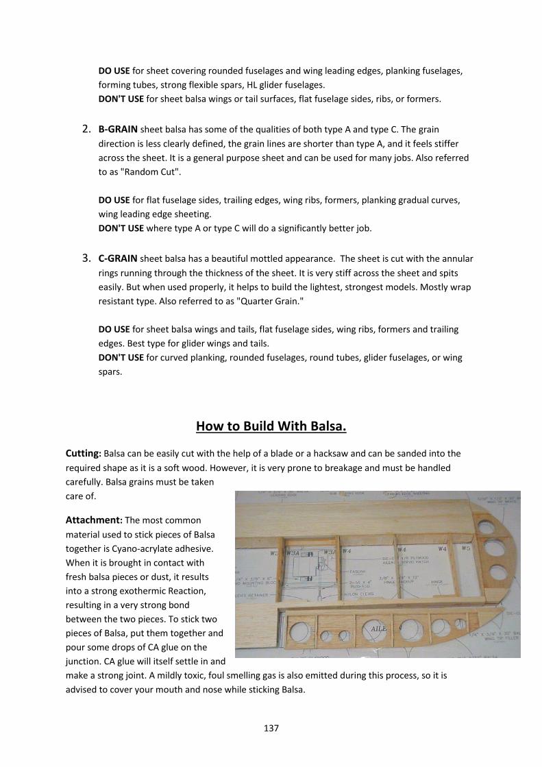
137
DO USE for sheet covering rounded fuselages and wing leading edges, planking fuselages,
forming tubes, strong flexible spars, HL glider fuselages.
DON'T USE for sheet balsa wings or tail surfaces, flat fuselage sides, ribs, or formers.
2. B-GRAIN sheet balsa has some of the qualities of both type A and type C. The grain
direction is less clearly defined, the grain lines are shorter than type A, and it feels stiffer
across the sheet. It is a general purpose sheet and can be used for many jobs. Also referred
to as "Random Cut".
DO USE for flat fuselage sides, trailing edges, wing ribs, formers, planking gradual curves,
wing leading edge sheeting.
DON'T USE where type A or type C will do a significantly better job.
3. C-GRAIN sheet balsa has a beautiful mottled appearance. The sheet is cut with the annular
rings running through the thickness of the sheet. It is very stiff across the sheet and spits
easily. But when used properly, it helps to build the lightest, strongest models. Mostly wrap
resistant type. Also referred to as "Quarter Grain."
DO USE for sheet balsa wings and tails, flat fuselage sides, wing ribs, formers and trailing
edges. Best type for glider wings and tails.
DON'T USE for curved planking, rounded fuselages, round tubes, glider fuselages, or wing
spars.
How to Build With Balsa.
Cutting: Balsa can be easily cut with the help of a blade or a hacksaw and can be sanded into the
required shape as it is a soft wood. However, it is very prone to breakage and must be handled
carefully. Balsa grains must be taken
care of.
Attachment: The most common
material used to stick pieces of Balsa
together is Cyano-acrylate adhesive.
When it is brought in contact with
fresh balsa pieces or dust, it results
into a strong exothermic Reaction,
resulting in a very strong bond
between the two pieces. To stick two
pieces of Balsa, put them together and
pour some drops of CA glue on the
junction. CA glue will itself settle in and
make a strong joint. A mildly toxic, foul smelling gas is also emitted during this process, so it is
advised to cover your mouth and nose while sticking Balsa.

138
Construction tips:
1. While building with Balsa, we always need to correctly judge what direction we need to cut
it in, along the Grain Lines or perpendicular to it. The pattern of grain lines on a piece of
Balsa is a key factor in deciding what part of plane can be made from it.
2. C Grain Balsa, because of its stiffness, is used to construct Wing Ribs and flat fuselage sides
and ribs. B Grain Balsa, also having nearly the same properties, can be used to construct
them. C Grain is also used to make the ailerons and the empennage. A Grain Balsa, due to its
flexible and easy to bend properties, is used to create rounded or planking fuselages, as it
can be easily bent by soaking in water. It is also used to create the leading edges of wings as
well as spars.
3. In general, Balsa is used to create the framework of the entire plane. It acts as a light but
sufficiently strong internal skeleton. It is in general coupled with a covering material such as
plastic sheet or MonokoteTM heat shrink sheets.
9.2.2) Coroplast Sheet
Coroplast is a brand name of Corrugated Plastic and a registered trademark of Coroplast, Inc.
Because of the success of this brand, it has become a generically used trade name and many people
refer to all Corrugated Plastic as "Coroplast".
Corrugated plastic or Corriboard refers to a
wide range of extruded twin wall plastic-sheet
products produced from high-impact polypropylene.
It consists of two parallel plastic sheets with vertical
spars between them. The channels created by these
spars are termed 'Flutes'. When working with
Coroplast, always ensure that you are thinking about
the direction in which the flutes travel. Manufacturers
typically offer a wide variety of colors and thicknesses
(quite commonly 4 mm). At regular temperatures
most oils, solvents and water have no effect, allowing
it to perform under adverse weather conditions.
How to Build With Coroplast.
Cutting: The best tool for cutting Coroplast in the required shape is a Blade. As it is just made up of
plastic, it is very easy to cut Coroplast in different shapes. Coroplast contains Flutes running the
entire length of the material. These flutes offer both strength and versatility. Cutting in the same
direction as the flutes is easiest, as the flutes guide the direction of the cut. Cutting against the
direction of the flutes is also not that difficult. The most challenging direction is one that is neither

139
parallel nor perpendicular to the flutes but rather at
an angle. The texture of the cut keeps changing. Being
slow and steady seems to offer the best results in this
case.
Tip: When cutting at an angle across flutes, use a
ruler. And cut on the OUTSIDE of the shape that you
are cutting out to ensure that the shape itself doesn’t
suffer damage.
Attachment: Joining two pieces of Coroplast is most easily done using CA glue. Such adhesives
provide enough strength to stick two pieces of Coroplast firmly and create a strong bond. For
sticking Coroplast to Thermocol, normal CA glue cannot be used as it melts Thermocol, therefore
always use only epoxy adhesives to make a bond between Coroplast and Thermocol.
Coroplast is usually used to make very durable (nearly indestructible) gliders or planes, with
the airfoil, control surfaces and sometimes even the fuselage made up of Coroplast by simple
processes of cutting, folding and gluing. These planes are very easy to make and extremely durable.
Coroplast sheets are also used as control surfaces in Thermocol planes.
Construction tips:
1. Coroplast is a very suitable material for making control surfaces as it is very easy to make a
hinge in it. To make a hinge in Coroplast, all you need to do is to cut out one entire flute but
only on one side. Look at the cross section. It will be a square with one edge being a part of
the upper surface and the opposite surface being a part of the lower surface. Pick any one
side and cut out ONLY that side of the flute. You will be left with a hinge that consists of a
piece of coro that holds together the two halves of the hinge and is extremely flexible.
2. Since Coroplast is a very thin material, it is better to use washers when driving screws
through the sheet. This makes sure that the sheet doesn’t tear out from under the screw.
9.2.3) Depron
Depron is a plastic material which consists of fine-
mesh expanded polystyrene. It is a very lightweight,
waterproof material, which allows for easy cutting and
gluing while it is not likely to break. Unlike materials such as
balsa, Depron modeling foam does not have a grain and
therefore does not split.
Depron is available in two types- ‘Depron’ and
‘Laminated Depron’. Laminated Depron is basically a sheet
of Depron pressed between layers of plastic coating. This

140
provides extra strength and turgidity to the Depron. Depron sheets are available in various
thicknesses, like 2mm, 3mm and 6mm and so on.
How to build with Depron?
Cutting: Sheets can be cut with any sharp blade but there is a great tendency to crumble at the
edges if proper care is not taken while cutting. Sanding and
shaping of Depron parts is an easy task achievable by simple
sand paper, without roughing up the surface.
Attachment: The most commonly used method to stick
Depron is a hot glue gun. Due to Depron being composed of
polystyrene, CA glue eats through it. While sticking Depron
with hot glue, care should be taken that the nose of the glue
gun does not touch the Depron sheet, as the high
temperature of the glue gun can melt Depron.
Construction tips:
1. Making hinges with Depron is a very easy task. To make a hinge/control surface, make the
appropriate cut. Take the two cut pieces and line up the surfaces that have been cut. Now,
they will fit together perfectly. But you will notice that it is not possible to pivot the pieces
around the point of contact. So, taper down the face to a point as indicated in the following
diagram. Once the tapering has been performed, a drop of hot glue is put on the non-
tapered side of the hinge and is spread along the entire length using a small piece of card or
a suitable object. Once the glue dries, the hinge is capable of movement to either side.
2. As Depron is a very light-weight and flexible material, we must increase the strength and
rigidity of the fuselage and the wing by using carbon fiber rods along the spar and to re-
enforce the fuselage. These can be attached with the help of a hot glue gun.
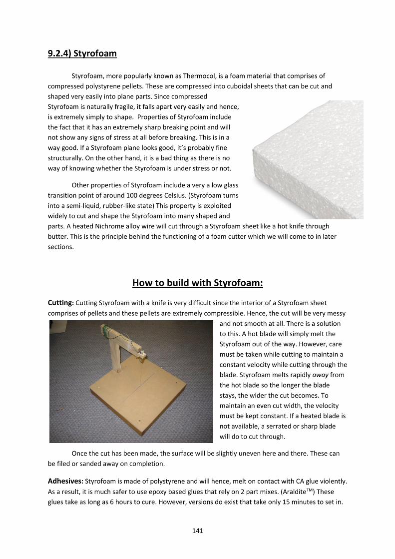
141
9.2.4) Styrofoam Styrofoam, more popularly known as Thermocol, is a foam material that comprises of
compressed polystyrene pellets. These are compressed into cuboidal sheets that can be cut and
shaped very easily into plane parts. Since compressed
Styrofoam is naturally fragile, it falls apart very easily and hence,
is extremely simply to shape. Properties of Styrofoam include
the fact that it has an extremely sharp breaking point and will
not show any signs of stress at all before breaking. This is in a
way good. If a Styrofoam plane looks good, it’s probably fine
structurally. On the other hand, it is a bad thing as there is no
way of knowing whether the Styrofoam is under stress or not.
Other properties of Styrofoam include a very a low glass
transition point of around 100 degrees Celsius. (Styrofoam turns
into a semi-liquid, rubber-like state) This property is exploited
widely to cut and shape the Styrofoam into many shaped and
parts. A heated Nichrome alloy wire will cut through a Styrofoam sheet like a hot knife through
butter. This is the principle behind the functioning of a foam cutter which we will come to in later
sections.
How to build with Styrofoam:
Cutting: Cutting Styrofoam with a knife is very difficult since the interior of a Styrofoam sheet
comprises of pellets and these pellets are extremely compressible. Hence, the cut will be very messy
and not smooth at all. There is a solution
to this. A hot blade will simply melt the
Styrofoam out of the way. However, care
must be taken while cutting to maintain a
constant velocity while cutting through the
blade. Styrofoam melts rapidly away from
the hot blade so the longer the blade
stays, the wider the cut becomes. To
maintain an even cut width, the velocity
must be kept constant. If a heated blade is
not available, a serrated or sharp blade
will do to cut through.
Once the cut has been made, the surface will be slightly uneven here and there. These can
be filed or sanded away on completion.
Adhesives: Styrofoam is made of polystyrene and will hence, melt on contact with CA glue violently.
As a result, it is much safer to use epoxy based glues that rely on 2 part mixes. (AralditeTM) These
glues take as long as 6 hours to cure. However, versions do exist that take only 15 minutes to set in.

142
These fast setting epoxy glues can be used to glue parts that cannot be held in the same position for
a long while.
Construction Tips:
1. The best part about Styrofoam is that it’s friendly to sand paper. Shapes can be drawn on
the side section of a Styrofoam piece and the entire piece can be sanded to form an
extrusion of that shape. This is extremely useful in making precise airfoils. The airfoil is
drawn on the side of the foam piece. Enough Styrofoam is cut off the piece with the help of
a foam cutter such that the piece is only slightly bigger than the required cross section. The
rest can be precision sanded to make the required shape. The smoothness of finish can be
increased by using finer and finer sand paper.
2. Styrofoam control surfaces are difficult to make. Instead, form the fuselage and the wing
from the previous procedure and use Coroplast or Depron for the control surfaces.
3. To seal up gaps or attach two pieces of Styrofoam, first, grind up some Styrofoam into fine
dust. Apply a drop or coat of epoxy glue to the junction and layer some Styrofoam dust onto
it. Repeat the procedure until the junction becomes smooth over. Repeatedly compress
each layer of dust as you add it to provide maximum strength.
4. Apply a coat of epoxy glue around parts of the Styrofoam that are prone to come under
stress – the wing mounts, tail taper, landing gear mount, engine mount, etc.

143
9.3) TOOLS REQUIRED
A variety of tools are required to construct an RC Plane. Ranging from a small Blade to a
Foam Cutter, each of the tools has its own importance and utility. The various uses of several
different types of tools are covered in this section of the handbook. The tools covered are:
1. Blade
2. Hacksaw
3. Foam cutter
4. Drill
5. Soldering Iron
6. Hammer
7. Screw driver
8. Sand paper
9.3.1) Blade One of the smallest yet most regularly used tools is a cutter/blade. A blade can be efficiently used to
cut sheets of Coroplast, Depron, balsa and thin sheets of foam
too. It is sometimes used even for cutting wires and plastic
sheets. This is one of the tools that should always be around
you during a building session.
To remember:
1. Always use a sharp blade. A blunt blade is no good.
2. Take precautions while handling a Blade. Do not cut
yourself or others with the sharp edge.
3. As the leading edge of the blade blunts off, cut out the
front part using the cutter provided at the end.
9.3.2) Hack Saw
A hacksaw is a fine-tooth saw with a blade held
under tension in a frame, used for cutting materials such
as metal or plastics. It can also be used to cut through
large sheets of foam. Hand-held hacksaws consist of a
metal arch with a handle, with pins for attaching a narrow
disposable blade.
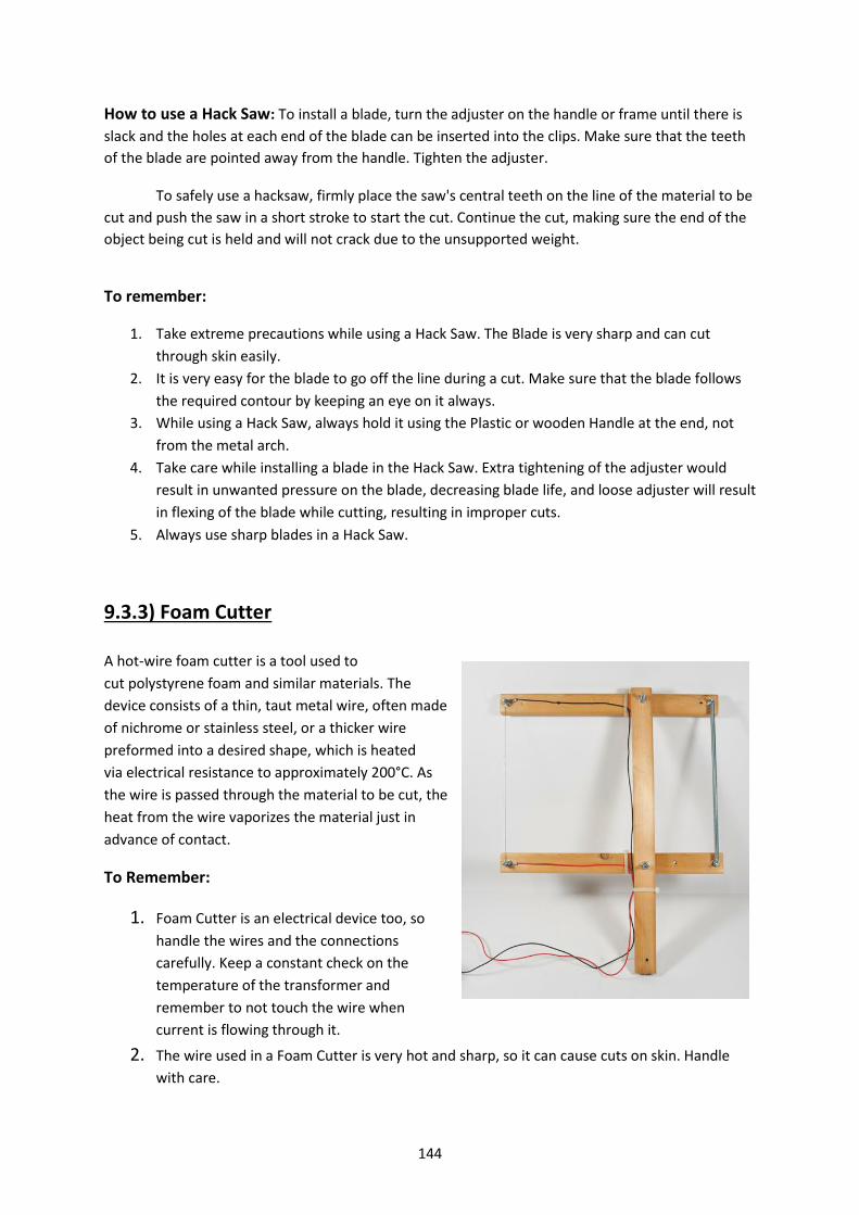
144
How to use a Hack Saw: To install a blade, turn the adjuster on the handle or frame until there is
slack and the holes at each end of the blade can be inserted into the clips. Make sure that the teeth
of the blade are pointed away from the handle. Tighten the adjuster.
To safely use a hacksaw, firmly place the saw's central teeth on the line of the material to be
cut and push the saw in a short stroke to start the cut. Continue the cut, making sure the end of the
object being cut is held and will not crack due to the unsupported weight.
To remember:
1. Take extreme precautions while using a Hack Saw. The Blade is very sharp and can cut
through skin easily.
2. It is very easy for the blade to go off the line during a cut. Make sure that the blade follows
the required contour by keeping an eye on it always.
3. While using a Hack Saw, always hold it using the Plastic or wooden Handle at the end, not
from the metal arch.
4. Take care while installing a blade in the Hack Saw. Extra tightening of the adjuster would
result in unwanted pressure on the blade, decreasing blade life, and loose adjuster will result
in flexing of the blade while cutting, resulting in improper cuts.
5. Always use sharp blades in a Hack Saw.
9.3.3) Foam Cutter A hot-wire foam cutter is a tool used to
cut polystyrene foam and similar materials. The
device consists of a thin, taut metal wire, often made
of nichrome or stainless steel, or a thicker wire
preformed into a desired shape, which is heated
via electrical resistance to approximately 200°C. As
the wire is passed through the material to be cut, the
heat from the wire vaporizes the material just in
advance of contact.
To Remember:
1. Foam Cutter is an electrical device too, so
handle the wires and the connections
carefully. Keep a constant check on the
temperature of the transformer and
remember to not touch the wire when
current is flowing through it.
2. The wire used in a Foam Cutter is very hot and sharp, so it can cause cuts on skin. Handle
with care.

145
3. Make sure that nobody is touching the foam cutter when you turn it on. And make sure
nobody touches it for a while after you switch it off.
9.3.4) Drill machine
A drill is a machine that converts
rotational motion into translational power
with the help of a screw. This type of
arrangement is used to remove material
such that the result is a hole. This screw
like attachments is known as a drill bit. The
attachment is gripped by a chuck at one
end of the drill and rotated while pressed
against the target material. The tip, and
sometimes edges, of the cutting tool do
the work of cutting into the target
material. The rest of the drill bit shaft
transfers the cut material out of the hole,
making way for new material to be drilled.
To remember:
1. Drill is an electrical machine, so be careful not to touch any live wires when connected to the
supply, and insulate all cuts, if any, before using the Drill.
2. Drill machine works at very high RPM, so take care not to hurt yourself or anyone else with a
while using the Drill. Always hold the work piece either with the help of a holder or at a
distance from the part to be drilled.
3. When attaching a Drill Bit to the Chuck, take care as to tighten the chuck properly. Loose
drill bits can come off at high RPM and lead to accidents or damage to the work piece.
4. Drill bits are prone to heating and hence, cracking. Drill only in short bursts and if your drill
does over heat, wait for it to cool down naturally and do not force it to cool down. This will
cause the internal structure of the drill bit to weaken and eventually, fracture.

146
9.2.6) Soldering Iron
A soldering iron is a hand tool used for
soldering. It supplies heat to melt solder, which is
an alloy of Tin and Lead that has a low melting
point. This alloy is also electrically
conducting. Solder is generally used on a small
scale to make electrical connections between
surfaces that aren’t naturally connecting each
other. It conducts electricity as well as
mechanical attaches the conducting surfaces
together like an adhesive. Soft solder is what is
most often thought of when solder or soldering is
mentioned and it typically has a melting range of 90 °C to 450 °C.A. A Soldering iron is composed of a
heated metal tip and an insulated handle. Heating is often achieved electrically, by passing an
electric current through a resistive heating element.
As is with all conjoining processes, soldering involves the use of flux. The purpose of solder flux is
to facilitate the soldering process. The obstacle to a successful solder joint is an impurity at the site
of the union, e.g. dirt, oils or oxidation. The impurities can be removed by mechanical cleaning or by
chemical means, but the elevated temperatures required to melt the solder encourages the work
piece (and the solder) to re-oxidize. This effect is accelerated as the soldering temperatures increase
and can completely prevent the solder from joining to the work piece, called a COLD SOLDER. Some
fluxes go beyond the simple prevention of oxidation and also provide some form of chemical
cleaning (corrosion). Fluxes for soft solder are currently available in three basic formulations:
1. Water-soluble fluxes - Higher activity fluxes designed to be removed with water after
soldering.
2. No-clean fluxes - Mild enough to not "require" removal due to their non-conductive and
non-corrosive residue. These fluxes are called "no-clean" because the residue left after the
solder operation is non-conductive and won't cause electrical shorts.
3. Traditional rosin fluxes - Typically an acid, which increases the wettability of metals to which
it is applied by removing existing oxides. The residue resulting from the use of rosin flux
is corrosive and must be cleaned.
To Remember:
1. Always use as little amount of solder and flux required for a specific joint. Extra solder
sometimes leads to short circuits, hard to de-solder joints and compromises with the
neatness of the joint. It can also lead to heating and improper conduction. Cover and
insulate the soldered joints with the help of a shrink tubing.
2. Soldering Iron is an electric tool, so be careful with wires and supply. Negligence may lead to
solder iron burning and shorting the wires.
3. Before soldering, clean the tip of the soldering iron by a sandpaper.

147
4. Soldering Iron attains very high temperatures if kept on for long, so make sure not to ever
check the temperature of the soldering iron by touching its tip. Also keep it out of reach of
children or it might lead to accidents.
5. Always keep the soldering iron either in a stand or at some strong metal/concrete base.
Make sure it does not touch its own wire, someone’s clothing or any other material. It can
lead to charring or injury.
9.2.6) Screw Driver
A Screw Driver is a tool used to drive
screws or bolts with special slots/tip designs into
place. A Screwdriver amplifies the hand's turning
motion to the small, specially designed tip that is
inserted into the screw's head. There are
numerous tip designs for special applications, but
the two most common are standard (also called
flat, flared, or straight) and Phillips (X-shaped)
tips. A Screwdriver is a must to be alongside you
if you’re working with screws or bolts.
To Remember:
1. Screwdriver kits have several types and shapes of screw heads. Out of all screw heads, the
alan keys (hex head keys) are the most important as they are used for small BLDC assembly
screws.
2. The longer the length of the Screwdriver, the easier it would be to tighten a screw/bolt.
9.2.7) Hammer A hammer is a tool meant to deliver an impact to an object. The
most common uses of a Hammer are for driving nails, fitting parts
and breaking up objects. Hammers are often designed for a specific
purpose, and vary widely in their shape and structure. The usual
features are a handle and a head, with most of the weight in the
head.
To Remember:

148
1. Always hold the object to be hammered using either a holder or from a distance to the
portion to be hammered.
2. A Hammer is a very heavy tool, so take
precautions not to let it fall down or hurt
yourself or anyone else with it.
9.2.8) Sand Paper
Sandpaper, also known as glass paper, is a
heavy paper with abrasive material attached to its
surface. It is used to remove small amounts of material
from surfaces, either to make them smoother, to remove a layer of material or sometimes to make
the surface rougher (e.g. as a preparation to gluing).
There are many varieties of sandpaper, with variations in the paper or backing, the material
used for the grit, grit size, and the bond.
To Remember:
1. Sand Paper is very rough and has abrasive material on the top, so take precaution to not rub
your skin or clothing against it.
2. We generally use two kinds of sandpaper, ROUGH and SMOOTH. Sandpaper has extensive
use in sanding thermocol sheets into precise airfoil shapes.
3. On materials where sandpaper would have no effect (wood and metal), we use a metal filer.

149
9.4) ADHESIVES
Adhesives are defined as substances, normally liquids or semi-liquids; those attach to other
surfaces and join the surfaces together. In most situations, surfaces are too rough at a microscopic
level to fit perfectly into each other. Adhesives fill in these gaps and then, attach the two surfaces
together.
Some handy tools exist that serve as adhesives but aren’t exactly an adhesive themselves.
One such example is cello tape, which makes use of a thin sheet of plastic paper that is coated with
glue. This following section will cover all the following:
1. CA glue.
2. Epoxy glue.
3. Hot melt adhesive.
4. Resins.
9.4.1) CA Glue
Cyano-Acrylate glue, abbreviated as CA glue, is the proper name for the more commonly known
super glue. CA glue is an extremely powerful glue that is used on a small scale to hold objects
together. In industry, CA glue is sometimes used as a temporary fixture before the appropriate
process can be carried out (welding/resin application) However, it is strong enough to be used as the
main adhesive in RC flying. CA glue is waterproof and hence, finds a place in RC submarines also.
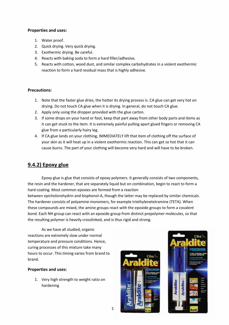
150
Properties and uses:
1. Water proof.
2. Quick drying. Very quick drying.
3. Exothermic drying. Be careful.
4. Reacts with baking soda to form a hard filler/adhesive.
5. Reacts with cotton, wood dust, and similar complex carbohydrates in a violent exothermic
reaction to form a hard residual mass that is highly adhesive.
Precautions:
1. Note that the faster glue dries, the hotter its drying process is. CA glue can get very hot on
drying. Do not touch CA glue when it is drying. In general, do not touch CA glue.
2. Apply only using the dropper provided with the glue carton.
3. If some drops on your hand or foot, keep that part away from other body parts and items as
it can get stuck to the item. It is extremely painful pulling apart glued fingers or removing CA
glue from a particularly hairy leg.
4. If CA glue lands on your clothing, IMMEDIATELY lift that item of clothing off the surface of
your skin as it will heat up in a violent exothermic reaction. This can get so hot that it can
cause burns. The part of your clothing will become very hard and will have to be broken.
9.4.2) Epoxy glue Epoxy glue is glue that consists of epoxy polymers. It generally consists of two components,
the resin and the hardener, that are separately liquid but on combination, begin to react to form a
hard coating. Most common epoxies are formed from a reaction
between epicholorohydrin and bisphenol-A, though the latter may be replaced by similar chemicals.
The hardener consists of polyamine monomers, for example triethylenetetramine (TETA). When
these compounds are mixed, the amine groups react with the epoxide groups to form a covalent
bond. Each NH group can react with an epoxide group from distinct prepolymer molecules, so that
the resulting polymer is heavily crosslinked, and is thus rigid and strong.
As we have all studied, organic
reactions are extremely slow under normal
temperature and pressure conditions. Hence,
curing processes of this mixture take many
hours to occur. This timing varies from brand to
brand.
Properties and uses:
1. Very high strength to weight ratio on
hardening
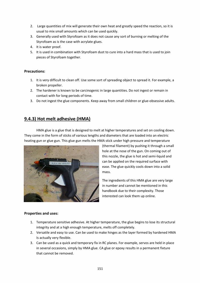
151
2. Large quantities of mix will generate their own heat and greatly speed the reaction, so it is
usual to mix small amounts which can be used quickly.
3. Generally used with Styrofoam as it does not cause any sort of burning or melting of the
Styrofoam as is the case with acrylate glues.
4. It is water proof.
5. It is used in combination with Styrofoam dust to cure into a hard mass that is used to join
pieces of Styrofoam together.
Precautions:
1. It is very difficult to clean off. Use some sort of spreading object to spread it. For example, a
broken propeller.
2. The hardener is known to be carcinogenic in large quantities. Do not ingest or remain in
contact with for long periods of time.
3. Do not ingest the glue components. Keep away from small children or glue-obsessive adults.
9.4.3) Hot melt adhesive (HMA) HMA glue is a glue that is designed to melt at higher temperatures and set on cooling down.
They come in the form of sticks of various lengths and diameters that are loaded into an electric
heating gun or glue gun. This glue gun melts the HMA stick under high pressure and temperature
(thermal filament) by pushing it through a small
hole at the nose of the gun. On coming out of
this nozzle, the glue is hot and semi-liquid and
can be applied on the required surface with
ease. The glue quickly cools down into a solid
mass.
The ingredients of this HMA glue are very large
in number and cannot be mentioned in this
handbook due to their complexity. Those
interested can look them up online.
Properties and uses:
1. Temperature sensitive adhesive. At higher temperature, the glue begins to lose its structural
integrity and at a high enough temperature, melts off completely.
2. Versatile and easy to use. Can be used to make hinges as the layer formed by hardened HMA
Is actually very flexible.
3. Can be used as a quick and temporary fix in RC planes. For example, servos are held in place
in several occasions, simply by HMA glue. CA glue or epoxy results in a permanent fixture
that cannot be removed.
152
Precautions:
1. The glue gun and glue get very hot on application. Take the necessary precautions.
2. The glue gun takes some time to warm up. Never ever test the temperature using touch. You
will know when the gun is ready by pulling on the trigger slightly and noting if any melted
glue comes out the end.
3. While using HMA on a foam surface, DO NOT touch the tip to the foam surface as this will
cause it to melt and will damage the foam. Use low temperature HMA glue for this purpose.
9.4.4) Resins Resins are artificially manufactured polymers that are similar in structure to a plant and tree
resins. They are manufactured to possess highly adhesive properties and are generally used to form
permanent fixtures. Resins consist of different types of polymers depending on the use or method of
application, etc.
Most resins are slow curing compounds as they rely on organic processes. They form
moisture resistant coatings and hence, find a lot of use in the marine industry. They form a hard and
permanent fixture on drying. Resins are classified into different types based on the material on
which they are used.
Properties and uses:
1. Slow setting. Very strong bond formed on curing.
2. Moisture resistant.
3. Resistant to temperature and pressure variations.
Precautions:
1. Do not ingest resins.
2. Some resins are known to be carcinogenic on long exposure. Mediate your usage of them.

153
CHAPTER 10
YOUR RC
154
10.1) INTRODUCTION
RC is the short form of Radio Controller. An RC is the gadget that is used to control an
aircraft in the air wirelessly. RCs function through some complex electronics that are beyond the
scope of this book and can be researched by those interested. However, the fundamental
functioning of the RC is as follows.
The entire RC system consists of 2 parts – the actual controller that is held in hand and a
small receiver unit that is mounted on the aircraft and connected to the necessary throttle and servo
channels. When a control input is given on the controller’s sticks or switches, the corresponding
signal is transmitted to the receiver which interprets it and operates the remaining servos and
throttle channels that are connected to it. The receiver unit draws power from the plane’s own
battery.
RCs come in a large number of designs and specifications which are tailored as per the
capabilities of the aircraft or the usage of the buyers. This chapter will deal with the following
aspects of RCs:
1) Classification.
2) Parts of an RC.
3) How to hold and use.
4) RC Modes – Stick configuration and plane type.
5) Receiver and pairing.
6) RC Menus, Options. (Important)
7) Conclusion

155
10.2) CLASSIFICATION OF RC’S
RCs are classified based on several different factors. These factors include:
1) Number of channels
2) Type of plane flown
3) Frequency
4) Etc.
Since the most important one among these options is the number of channels, we will be dealing
with this in greater depth. We will also see that the number of channels will also determine the type
of planes that can be flown.
Two Channel RCs
Mainly, two channel RCs have one channel for throttle control and another channel that
controls yaw. This effectively means that there is no pitch control whatsoever and once the plane
has been hand launched, it must be flown at the same height or the height will change depending on
the wind. Yaw is controlled by a rudder and dihedral wing couple that will give the plane some roll
capability on yawing. Also, Yaw can also be controlled by differentially varying throttle in case of
multi engine planes.
Most planes that can be flown by 2 channels are cheap and very tiny planes that can be
flown by children without any flying skill. They are highly stable with dihedral wings and can take
quite a beating. This kind of RC and plane dual is generally meant for people who are JUST starting
out with RC flying or are buying a Christmas gift for a child.
Three Channel RCs
Three channel RCs have one channel for throttle, one channel for pitch and one channel for
yaw. Roll cannot be controlled and hence, the planes controlled by 3 channel RCs are also with
dihedral to give them roll stability.
Three channel RCs are generally used by amateur aeromodellers in combination with a
stable glider to get a feel for the RC and flying. The roll resulting from the adverse yaw will also be
partially controlled by the yaw channel and can hence, the yaw channel can be used for a very well
executed turn. Some helicopters can also be flown with 3 channel RCs but these helicopters are, in
turn, birthday gifts and can be flown by anybody with enough cash.
Four Channel and above
Four channel RCs contain one channel each for throttle, roll, pitch and yaw. They also have a
number of smaller knobs and dials that control other servos on the plane and are hence, also
labelled channels. The number of channels on an RC can sometimes go upto 12 or 14. This does not
mean that there are actually 6 or 7 analog sticks but only that so many more servos can be
controlled by a flick of some switches.

156
Four channel RCs are used by experienced aeromodllers to fly planes that are capable of a
large number and range of flight manoeuvres. The dials and knobs also enable the flyer to control
complex aircrafts such as helicopters or aircraft capable of VTOL, VSTOL, etc.
Most RC modellers will have a hardy 4 channel RC in hand with a large number of auxiliary
channels.
Fig: As indicated, two channel and a four channel RC.
10.3) HOW TO HOLD AND USE AN RC
Yes there’s actually a separate section on how to hold, use and store your RC. This is because
a lot of people simply do not handle RCs well. Without an RC and a receiver maintained properly,
you plane is probably just going to sit there looking pretty. Read the following section carefully.
10.3.1) Holding and using
1. Grip your RC with both hands. Some RCs come with grips on the side.
2. Adjust the stick length as per your convenience and the sensitivity of the plane. Longer sticks
mean less sensitivity. LOL.
3. Place each thumb on each of the control sticks on top. The mildly spike projection on top will
help to grip your thumb.
4. Some flyers prefer to use their index fingers and thumbs to hold the control stick. This is
known as the pinch style of control.

157
5. Use index fingers to flip any switches as such. ‘
6. Hold the RC at any height that is convenient.
7. Position the antenna at the appropriate orientation depending on where you’re going to fly
the plane.
8. Preferably, get someone else to set up the plane’s launch or hand launch. You must focus on
maintaining control of the plane at all instants of time. Sometimes, It’s just good fun to try
and through the plane with one hand and get back to controlling it before it’s too late.
9. If you are wearing a neck strap, wear it at a comfortable length. Whatever is comfortable to
you will do. Make sure that you don’t accidentally hit any control switches or knobs with
your stomach and chest as the RC has a tendency to flip such that the control sticks meet
with the body.
Fig: A person wearing a neck strap holding an RC in the correct manner.
10.3.2) Maintenance
As is the case with all sensitive electronic equipment, RCs require a good level of maintenance. Even
though they are made to withstand quite a bit, it’s better not to test their limits. The points for the
RC maintenance are not too different from that off any electronic device.
158
1. Your RC is not a fetch toy, a basketball or a hammer. Do not use it for anything other than
what it was meant to be used for.
2. Store the RC in a dry place away from moisture and temperature.
3. Disconnect the RCs battery when not in use for long periods of time.
4. Retract or fold the antenna when not in use.
5. Store the RC in such a way that there is no pressure on the control sticks and antenna.
6. Do not stress the antenna during use or storage.
7. Dust off your RC periodically since the dust can get into hard to reach places and cause
problems.
8. Don’t forcefully handle any of the knobs or switches or store them under stress for long
periods of time.
9. Don’t bring your RC near your work space. It is prone to getting covered with dust,
Styrofoam and adhesives.
10.3.3) Receiver
The importance of the receiver cannot be emphasized enough given its humble stature. It is
a sensitive piece of equipment and must be, sigh, handled with care. It is a very small gadget and is
very prone to loss. TAKE GOOD CARE of your receiver and always have a paired receiver spare with
you.
1. Involves small parts, keep away from small children.
2. The antenna of the receiver is very fragile. Do not store it or place it on the plane under
stress.
3. The pins in the receiver are also very fragile. Do not force a servo or ESC pin into it if it
doesn’t go in. The pins are very prone to bending.
4. Always keep your receiver paired with your RC.
5. Store in a clean, dry, dust free environment.
10.4) RC STICK MODES
RC Stick modes determine which axis of which control stick controls what channel. We can
all agree on the fact that each of the sticks has 2 axes of movement – up/down and left/right.
Depending on the channel number allotted to them, they are classified into 4 main types.
So what exactly is a channel? A channel is one set of 3-pins on the receiver. You will have
seen in the electronics section that a servo has a set of 3 wires together. This will fit into one set of
3-pins on the receiver. Hence, one axis of control take care of one channel which controls one servo,
ESC, gyro, etc.

159
The four modes are naturally called 1, 2, 3 and 4. By convention, they attach to the following
servos:
a. Channel 1: Rudder
b. Channel 2: Elevator
c. Channel 3: Throttle
d. Channel 4: Ailerons.
The channels that each axis of control operate are shown in the following four diagrams. Do note
that the most widespread control is mode 2 as this involves the main 2 control axes (Elevators and
ailerons) being on the same stick just like on the yoke stick of an actual aircraft, thus giving a very
realistic feeling of flying.

160
10.5) RECEIVER AND PAIRING
A receiver is the second half of your plane’s control system. It is a delicate piece of
equipment and must be handled with care. One receiver can only be paired with one RC at a time.
There are ways to connect 2 RCs physically and then pair them with one receiver so that a trainee
can be trained under a master RC on the same plane.
Structure: The receiver is a small cuboid that is an inch or two in each dimension. It has a delicate
coaxial antenna that can vary in length. It also has several sets of pins. Each set contains three
individual pins. Each one of these sets signifies one channel.
Function: The receiver performs what it has been named for. It receives signals from the RC,
interprets them and transmits them to the other components of the aircraft as per the inputs given
by the RC. The wires on servo motors, ESCs, gyros and other channel operated mechanisms are all
connected here. All receivers and RCs function at 2.4Ghz frequency.
Maintenance:
1. Store your receiver in a dry place without temperature extremes.
2. Never store or use your receiver in a position where the antenna is stressed. Take care that
the antenna’s root is especially free of stress. The antenna is coaxial and hence, even mild
fraying will affect the antenna.
3. Always keep your receiver paired to your RC.
4. When mounting a receiver, make sure that the antenna does not touch any metal parts of
the plane as these will start acting like antennae themselves and catch stray signals that can
cause the plane to crash.
Fig: Note how the receiver (bottom most) is attached to the servo and the battery.

161
In some cases, the receiver is powered by its own separate battery pack as shown in the figure. In
most of the receivers that are used at Aero BPGC, you will find that the receiver draws its power
straight from the ESC which is connected to the battery.
Fig: The sets of 3 pins in each channel is clearly visible. Each channel controls a servo, ESC, gyro, etc.
Pairing
As was mentioned earlier, only one receiver can be paired to an RC. What is pairing? When a
receiver is paired to an RC, it means that that receiver will interpret commands sent only from that
particular RC and any attached trainer RCs. This is done so that when a large number of planes are
flying at the same time, interference does not occur. So how does pairing occur? The pairing
procedure differs from RC make to RC make so read up on your RCs manual as soon as you buy it.
Given below is a step by step process of the fundamentals that are at work when this happens.
1. Any RC, when not paired with a receiver, has a procedure by which it starts sending out
search signals to look for a receiver’s return signal. All other RCs in the region must be off or
far far away.
2. Once this has been initiated, (some RCs do it automatically when they can’t detect a
receiver) a procedure is initiated on the receiver by which the receiver detects the signal and
the sends a return signal. Some RCs might require the power to the receiver to be cut at
some stages, but the overall process takes less than a minute if you know how to do it.
3. An affirming beep or series of sounds and lights occur to show that the receiver has been
paired with the RC.
4. Sometimes, when the receiver draws its power from the ESC, the signal that the process is
successful is the initialization sound of the ESC.

162
10.6) RC MENUS AND OPTIONS
Now that we’ve determined how an RC works, let’s check out what types of options the RC
offers. While flying, and mind you just RC flying, there are hundreds of things that could vary. The RC
contains several menu options that control several parameters all over the plane. This following
section will deal with the most common menus and options found in 4+ channel RCs. Note that the
costlier and higher grade the RC, the more options it will offer. Hence, READ YOUR RC’S MANUAL.
10.6.1) Menus
Mode type: This option allows you to set the stick mode of the RC to mode 1, 2, 3 or 4. For what
each mode means, refer to the stick modes section of this chapter.
Transmission: Determines the type of transmission signal to use – PPM or PCM. Refer to the
transmission types section for more on these.
Reverse: Depending on the direction in which the servo has been mounted, a stick movement will
correspond to a direction of rotation of the servo. This might sometimes end up in a mess where left
rudder on the stick means right rudder on the plane and so on. Even the motor could be rotating in
the wrong direction! To reverse the required channel, there exists the reverse option. Before every
flight, you must check that each control surface moves in the required direction.
Trim and Sub trim: In short, when a servo is mounted to a control surface or a helicopter swash
plate, it might not be mounted in such a way that the zero on the RC corresponds to the mean
position of the servo arm. Trimming the plane is to make sure that both coincide. So what is the
difference between trim and sub-trim? Sub-trim is used on the ground to make the servos align as
per the required direction. Trim is used for making minor corrections in the air depending on the
aerodynamic effects and CG location of the plane.
Dual Rates: Sometimes, it’s important to control how sensitive the control surfaces are to control
stick movements. This becomes a very important factor in acrobatic planes that dance to the rhythm
of a background track. Normally, the throws of the control surfaces vary linearly with the control
stick movement. However, it is possible to vary the graph between the control input and the control
surface throws. Normal RCs offer two main options to vary the curve:
1. Reducing or increasing the maximum throws on either side of the control surface.
2. Varying the degree to which the graph varies exponentially. This can be a positive or
negative exponent.
Once the graph has been set, the x-axis represents the movement of the control stick and the y axis
represents the servo’s movements.

163
Fig: Changing the maximum throws of a servo
Fig: Changing the exponential value of the graph

164
Failsafe: What happens when for some reason or the other, the connection between RC and
receiver gets severed? What movements will the receiver make the servos execute? In such a case,
there exists an option on RCs called failsafe. The failsafe menu accepts preset values of throws for
the control surfaces. When the receiver cannot get a signal from the RC, it sets all the control
surfaces to these preset values so that the plane can still remain flying while a solution to the
problem can be found out.
Note: Failsafe is allowed only in PCM transmission.
Timer: In case of IC engine planes, when the fuel runs out, the engine stops immediately and
becomes a large source of drag. This is very much unlike electric planes where the reduction in
throttle with a depleted battery can be seen visibly and the plane can be landed accordingly. The
timer is generally operated by the trainer switch.
10.6.2) Options and mixing
Elevon mixing: In your experience, you might have noticed that jet planes and delta wing aircraft in
general, have two panels on their tails that can individually move up and down. By coordinating
which panel moves where when, roll and pitch can be executed. Elevon mixing relies on two control
surfaces, usually in the horizontal plane of the aircraft that are individually controlled by two
different servos.

165
V-tail mixing: V-tail mixing is for planes that have a mix between elevator and rudder. The tail is in
the shape of a V. This mixing works in the same way as an elevon mix does. Indicated in the diagrams
before is a clear indication of the movement of the control surfaces and the planes. When using a V-
tail, a natural question arises – when both control surfaces move left or right together, yaw occurs.
However, with respect to the direction in which the air is diverted, isn’t there a corresponding
adverse roll that occurs? Truth be told, the torque due to this angled diversion of air is too small to
roll the plane. This is why V-tail mixing is often seen in high aspect ratio planes which are highly roll
stable.
Elev-flap mixing: This mixing couple the flap and elevator servos. What happens is that when the
mixing switch is flipped, the elevator control stick controls the increase and drop of flaps. This is very
useful for making quick square turns and is generally used in pylon racers.
Snap roll: The snaproll option allows you to set one single switch to execute the snap roll
manoeuvre. This involves putting your plane into a stall and then using the rudder to complete a full
turn similar to an aileron turn. The snap roll menu contains options for setting the throws of
elevator, aileron and rudder during the entire snap roll process.

166
Airbrake: This function helps the plane to set airbrakes to make steep descents or to slow down
speeds during dives. It simultaneously sets the aileron, elevator and flaps to the appropriate
positions at the flick of a switch to make the corresponding aerodynamic changes.
Fig: A model jet with the airbrake mix turned on.
10.7) CONCLUSION
Now that you know how to operate and take care of your RC, it’s time to expand your
horizons and find out new uses for your RC. Always handle your RC like the expensive piece of
equipment that it is and take good care of it. Never lose your receiver ever as it is very troublesome
to order another one. We here at Aero BPGC try to save our equipment as much as possible and we
expect you to treat your equipment respectfully also.

167
CHAPTER 11
FLIGHT

168
11.1) FLYING – A GUIDE FROM TAKE OFF TO LANDING
Now you’ve followed all the steps and procedures to build your RC plane. It looks all flashy
and just about ready to fly. Problem is, you don’t know if you can fly it unless you’ve flown it.
In this chapter of the handbook, we will cover the following sections of RC flying:
1. Pre-flight check list.
2. Required tools and safety precautions
3. Start up procedures and rechecks.
4. Trim
5. Take-off
6. Climbing
7. Turning
8. Landing
9. Shut-down and post flight check list.
10. Troubleshooting and emergency procedures
11. Crash checklist.
11.2) POINTS TO REMEMBER WHILE FLYING
Always remember, flying is as dangerous as it is fun. Lots of expensive equipment and surrounding personnel are in stake of injuries. Remember, always obey the flying rules of your state or city and fly safely and not on the lines of insanity.
a. Make sure that you are flying in a legal airspace. Do not fly near airports or military bases without permits.
b. Airspaces must have large open spaces of ground below them for landing, take off and of course, crashing into.
c. Do not threaten or fly close to friends or animals in order to jolt them. If you lose control of the aircraft here, it can lead to certain injury.
d. When flying with a trainer, Master – Be liberal. Do not take control of the aircraft as soon as it twitches out of level flight. Your student is capable of level flight and turning at the least. If not, it was your fault to give him the RC in the first plane. Take the plane up to a high altitude and then only hand over the controls. If the plane comes too low, then take control. Take off and land the plane until the trainee is confident enough. Slave – Trust in your master’s judgment. Keep the plane high enough so that your trainer has enough time to recover from an error. You are still a novice, remember that.
e. When close to the ground and at low airspeed, don’t make sharp rolls. These will destabilize your plane and you will not have time to recover before a crash. The above problem often occurs on landing.
f. Don’t climb steeply close to the ground. If you stall, you could destroy the plane or endanger nearby individuals.

169
g. DO NOT fly into the sun or into a place where you cannot see your plane. You will lose orientation and crash the plane if you are unable to see it. In case you do so, Hand over your RC quickly to a senior who should be able to bring it back.
h. Do not, I repeat, DO NOT fly overheard. Gauging altitude, airspeed and orientation when a plane passes overhead is very difficult and a number of crashes have occurred because of the above.
i. Do not be IN A HURRY to fly. A lot of crashes have occurred because of overly eager people jumping the gun without performing the important pre flight checks.
j. If you are flying for the first time, start out with a 3 channel glider with dihedrals. Peace. k. LISTEN TO YOUR SENIORS. THEY ARE NOT ENTIRELY STUPID. THEY WROTE THIS BOOK. l. Fly confident, you own the skies! But don’t be a jackass and try a harrier roll on your first try.
Take it from us. O.o m. Have a safe flight. And pay attention during briefing sessions.
11.3) PRE-FLIGHT CHECKLIST
11.3.1) The Plane
When you set down your plane on a runway, before even thinking about connecting your
receiver to the channels, you must check if your plane is structurally sound and functional.
a) Visually inspect the plane for signs of wear and tear or damage. These may be in the form of
cracks, fraying pieces of material, or stress creases along the material used.
b) Thermocol/Styrofoam has a very sharp breaking point and will not show any deformation at
all and may break as soon as stress exceeds its limits.
c) Coroplast/Depron will show stress marks from shearing or longitudinal stress and are signs
that a fracture is about to occur. Large pieces of these materials are also prone to twisting
and hence, can largely affect the aerodynamics of the plane.
d) Balsa wood is very light and will start developing cracks even when handled a little heavily.
For wings with balsa ribs, it is advisable to jostle the wing very very gently to see if the wing
surpasses its flexibility. If it overly seems to wobble, it is best to look for cracks along the
wing frame. There have been instances where the wing has broken in half mid-flight. This is
often known as the Namaste Syndrome.
e) Check the landing gear. The landing gears support rods must not be bent. Both landing gears
must be at the same distance from the plane’s body. Both landing gears must be aligned
parallel, i.e., the line joining the centers of the landing gear must be parallel to the Y-axis of
the plane.
f) The Landing gear base/stab/undercarriage must be in-front of the cg (10-20% of fuse length
from cg) and must be flexible depending on trike or tricycle type landing gear) and angled
slightly forward (5-10 degrees) this ensures that the plane doesn’t do a nose-bash when
landing on grass.
g) Check the motor mount. Any loose screws must be tightened and any structural weakness
must be compensated for. Make sure the motor is pointing straight to assure a straight line
of thrust. If you have angled the thrust vector to the fuselage, make sure you check it’s in
the right position.

170
h) Make sure you check all the hinges to the control surfaces. A loose hinge might come off in
flight and make your plane crash. (You don’t really want your elevator to come off mid-flight,
do you?)
i) Propellers: Check if the props are installed on the prop-saver or the collet securely and in
the right orientation. The props provide thrust in the same direction even if they are
attached upside-down but are much less efficient. Many fliers have been known to fly for 4-
5 minutes with the prop on in the wrong orientation.
j) Balancing your CENTER OF GRAVITY: CG balancing is the one of the two most important pre
flight checks along with trimming. The center of gravity of the plane must be checked along
two axes. The X-Axis and Y-Axis.
Y-Axis: Place the fingertips at the two ends of the wing’s spar line (1/3rd of chord length from
leading edge) and check if the plane leans forward or back. Adjust your battery/electronics
as required.
X-Axis: Add small weights at the wingtips such as rocks or clay, to adjust the roll about this
axis. Since the weights are at a large distance from the CG, they need not be too large to
have a good contribution.
11.3.2) The Parts
Every plane comes with a large number of tiny parts and gadgets that at first, might seem to be
functioning fine, but are actually prone to damage. Malfunctioning servos or engines can result in
crashes or even human injuries. Hence, it is advisable to check all electronics once before take-off.
a) The servos – There are simply way too many things to remember while checking servos.
But here they are :
Make sure the servos are fastened properly whatever the mechanism is.
Make sure that the servos have the required throws in each direction
Re-verify your rates, graphs and sensitivity for each servo mechanism.
Make sure the servos are centered to their correct requirements. ALWAYS USE SUB-
TRIM on your RC to change the centering position.
Unless it’s a last resort, and nothing else is possibly, only then must you mechanically
change the centering of the servo at zero-trim
b) The control surfaces – Before your plane starts moving, please check the direction of your
control surfaces ONCE ATLEAST.
If the surface(s) does not turn in the correct direction, reverse the direction of the respective
channel(s) on your RC.
Sequence Test: If you are using differential ailerons or any other form of rate graph or Expo
Setting, verify the rate once by moving the control stick on your RC fully either way to check
if the control surface follows the graph correctly.

171
c) The engine – The first step is to make sure all your motor fastenings are tight and
screwed/glued properly. Then gently run your throttle until just when the propeller or
engine starts running. This is to make sure that your propeller rotates in the correct
direction. Feel the air behind the propeller to make sure that air gets pushed backwards. If
not, exchange TWO OF ANY THREE connections from the motor to the ESC. This will change
the throttle direction by changing 2 of the 3 phases of the source. You can also program the
ESC with either the ESC programmer or by manually programming the ESC. For further info,
see the ESC programming section.
d) Hold your plane tightly, and push your throttle lever to its maximum capacity or until you are
barely able to hold the plane. If you can feel the plane pulling hard, it means the motor is
generating enough lift for take-off.
Note: This is not entirely true. Even underpowered planes can fly; they just need airspeed
and a thrust component.
e) Connector cables - connector cables are three wired cables used to connect two distantly
separated components. Make sure the connector cables are connected in the correct
manner (red to red, and so on) and the pins inside are straight. A bent pin or a loosely
hanging wire may result in loss of Radio control midair.
11.3.3) The RC
RC’s in general have several methods in which they can be used, i.e., different motions of the control
sticks can translate to different control surfaces, look up the chapter on RC’s for more details. Each
one of these is called a stick mode. We normally use Mode 2, where the connections are
1: Aileron, 2: Elevator, 3: Throttle, 4: Rudder (Where 1,2 etc denote Channels)
BEFORE TAKE-OFF, CHECK YOUR RC’S STICK MODE CAREFULLY.
Channel 2 Elevator
Channel 1 Aileron/Rudder
Your Favorite RC Channel 3 Throttle (No Spring Action) Channel 4 Rudder
Trim Tabs

172
11.3.4) The Tools and Safety Kits
Make sure you have the following set of tools/equipment and safety precautions before you
start flying. The * items are of utmost importance and must constantly be a part any aeromodeller’s
kit.
a. Screwdriver KIT * j. Soldering iron
b. Pliers * k. Glue gun
c. Cellophane tape * l. Hacksaw
d. Tie wraps *
e. Insulation tape *
f. Lots of fevikwik/ CA glue *
g. Cutting Blade *
h. Double-sided tape *
i. Rubber bands *
j. Sandpaper *
Thankfully, all of the past flying at BITS Pilani Goa Campus has been done within a walking
distance of the medical center and hence, we’ve never really cared about self-safety.
But in case you’re flying with fuelled planes, HAVE A BUCKET OF WATER OR BETTER, SAND, and
CLOSEBY. In case of a crash, you don’t want be blinking at a nice warm fire, much less trying to put it
out with your favorite shirt. Do note that you will be dealing with OIL fires and most hydrocarbons
will burn on top of a layer of water. Hence, THE SAND.
11.4) START-UP PROCEDURES
You are about to start up your plane, RC and all of their necessary systems. Now, you can’t
just randomly switch everything on, plug everything in and expect all to be fine and function well. It’s
always safest to follow the following start up procedure point by point.
1. Make sure your RC is paired with your receiver. If not, check the handbook’s section on
RC >>> PAIRING
2. Turn on your RC. Some RCs require their switches to be in specific positions to turn on.
3. After your RC is on, move all trim tabs to their mean positions.
4. This following point cannot be emphasized enough. MAKE SURE YOUR THROTTLE CHANNEL
IS AT ZERO. Several injuries have been caused because of non-zero initial throttle by
propeller blades.
5. If you are using fuel, carefully calculate your fuel levels and set a timer on your RC so that
you have enough time to land.
173
6. If you are using batteries, the next step is to connect your batteries. Make sure that the
correct terminals are interconnected.(positive to positive and negative to negative)
Note: Do not rely on color coding as sometimes different manufacturers have different color
coding standards. Failure to do so will result in an excess current being drawn from the
battery and hence, the ESC will melt/burn.
Note: In such an emergency, do not hesitate to IMMEDIATELY PULL OUT the battery’s
terminal as fast as possible. You may have to pull on the wires and this might cause damage,
but try to pull out the terminal and not the wires as much as possible.
After connecting the battery, listen for the ESC’s unique initialization sound. If it does not do
so, repeat the process and check the pairing of your receiver and RC. If the problem persists,
refer to the RC chapter.
7. LIPO SAFETY- Make sure the LiPo battery is not close to any sharp or metal objects (nuts and
bolts) on the plane. This might cause the packaging of the LiPo to tear (due to vibrations
and/or hard landings or crashes) and that will damage the battery and will mostly render it
useless.
When you plug in the power supply, make sure it is tightly connected to the female port. The
LiPo must be secured well to the fuselage or the battery hatch.
Please Refer to BATTERIES section of this handbook for safety instructions.
8. Now, we must check the functioning of the servos. Make sure that all the servos move in the
correct directions as per their specific rate graphs and correspond to the correct channels.
For information on MIXING and REVERSING refer to the appropriate sections in the RC
chapter.
9. Run the throttle till the maximum limit allowed while holding the plane very firmly. This will
tell you if the thrust is enough to move and lift the plane.
10. Check the landing gear and other structures for damage from previous flights or hard
landings.
11. After thoroughly performing any inspection checks on the planes body and parts. You are
now ready to take off.
11.4.1) TRIM
By far, this is the most important pre-flight check you will ever perform. When you install a control
surface, the servo and control surface may not actually be at the neutral position. When the plane
goes up in the air, air begins to flow over these control surfaces and hence, causes mild movements
that may put the plane into irrecoverable spins or dives.
Basically, it means you’re offsetting the zero on the RC by a few notches so that the RC’s zero and
the actual neutral position coincide.
What trimming your aircraft does is to match the electronic centre of the stick with the actual
physical neutral point of the control surface. From here, the control surface will move to its
maximum positive and negative values. So how do you trim?

174
1. Look at your control surface visually from one side, and note the offset from the zero
position
2. Take your RC and follow the start-up procedure for switching on both plane and RC.
3. On your RC are trim tabs. Move the trim tabs in the required direction and note the
movement of the control surface also. MAKE SURE YOU USE SUB-TRIMS for this purpose.
The normal trims are for minute adjustments when the plane is in the air, soaring. Once the
control surface aligns in the neutral position (generally in line with the wing/stabilizer) you
are done with the trim. The differences are unique to each RC and you must read your RC
manual before using it.
Note: Even if at maximum trim, your control surface is not level, refer to the SERVO >> CENTERING
section.
11.5) TAKE-OFF
(Please read chapter on RC controls before this)
11.5.1) Launching
There are 2 methods of launching aircraft:
Launching mechanism: By hand, by catapult, by attached vehicle, etc.
Propulsion: Engines, Motors, Propellers, Etc.
Each mechanism demands certain specifications before launch. Note: ALWAYS LAUNCH/TAKE-OFF AND LAND THE PLANE IN A HEADWIND. NEVER TAKE-OFF AND LAND IN A TAILWIND. WHY? Check AERODYNAMICS chapter. Note: ONLY TAKE OFF IF YOU KNOW THAT YOUR PLANE CAN HANDLE THE WIND. Launching mechanism:
1. Throw fast. The faster the better. But stay within the structural limits of the plane, i.e., not so fast that the plane flutters.
2. Don’t throw or launch randomly. Give the plane a good positive angle of attack, around 4-8 degrees depending on the dimensions and capabilities of the plane. Give a negative angle and you can’t climb easily Too positive an angle and you will flip over or worse, stall.
3. Have enough clearance from the ground to recover from immediate falls. Recoveries from bad launches have been made with the plane being so low that the elevator touched the ground. NO UNDER-ARMS BOWLING DURING LAUNCHING. :P
4. In case of large planes like gliders, take a run up.

175
Fig: Hand-launch of a moss glider.
Propulsion:
Taking off with propulsion is an art form in itself and must be done gracefully and patiently to be done correctly. Take off procedures and feel vary from plane to plane and is hence, left to the pilot’s discretion.
1. Place the plane on the runway, facing as much into the wind as possible. Tailwinds seriously hinder lift and must be avoided during. As to why this happens is explained in the AERODYNAMICS OF FLIGHT chapter
2. Stand midway at the runway keeping the runway perpendicular to your eye direction. This ensures that you are able to gauge distance accurately. Head on landings and take offs are difficult to execute.
3. Make sure the plane has enough of a runway space. The bigger the plane, the larger the runway.
4. Clear your runway of any obstructions, people or animals and make sure it’s flat. 5. After moving your control sticks around to check if all channels are functional, you’re ready
for lift off 6. Increase throttle until your plane starts moving. 7. Gradually increase throttle until you see the plane lifting or up to full, whichever comes first. 8. Even if at maximum throttle, if the plane does not lift, STOP YOUR ENGINE IMMEDIATELY, it
could mean one of several things: a. Your battery could be low. b. The plane is too heavy for the lift generated. c. Your prop is on backwards. But still generating thrust
Stop the plane and check your battery by running at full throttle. Make the necessary adjustments to weight/lift.
Even now, if the plane does not take-off, it’s time to rethink your design.
9. During the throttle increase, your plane will tend to move left and right irregularly. MAKE CONSTANT YAW corrections with the rudder to keep your plane heading straight down the runway.
10. If the plane does not lift up of its own accord, give a gentle up elevator to give it a higher angle of attack. This should divert air further downwards and hence, create lift. Note: DO NOT CLIMB STEEPLY. This could result in a stall close to the ground. In most cases this is very very difficult to recover from and could destroy the plane.

176
Fig: Trainer plane taking off. Note the large throttle and mild positive angle of attack.
11.6) CLIMBING
Now your plane is off the ground and is in the air. But how do you reach cruise height? The following set of procedural points highlights what must be kept in mind while climbing to a cruise angle.
1. Keep your angle of attack small. Never climb steeply unless it’s completely necessary 2. Have enough thrust to sustain a small positive angle of attack. DO NOT CLIMB STEEPLY. 3. Climb in large circles. This will help to keep your plane within range 4. Proceed in steps of climbing followed by steps of level flight. This will keep the engine from
exerting itself. 5. If you feel that the plane is stalling as you climb, you can do one of two things
a. Increase the throttle. b. Put the nose down and level the plane.
If neither seems to work, land your plane and check the weight, thrust and design of the plane and also, check the battery levels.
6. Once you have reached your cruising altitude, gently level off the plane and enjoy your flight.

177
Fig: Note the gentle up elevator on climbing. This is followed by leveling followed by another step of climbing.
11.7) TURNING
Well, it’s kind of obvious isn’t it? You can’t ALWAYS fly in a straight line forever. Point is, turning is slightly more complex in an airplane than it is in a car or a cycle. It involves several control surfaces and lots of things can go wrong if you don’t bank properly.
Now, there are two ways in which you can turn: with YAW and with ROLL Turning with YAW is normally not used at all unless it’s to make very minor adjustments to a flight path or to align during landing or take off. Turning with ROLL or BANKING is the most frequently used method of turning. Use the following point to make a clean banked curve.
1. Ailerons bank your planes, making them rotate around the X-axis. 2. Bank your plane in the required direction of the turn. 3. Now that you have changed the lift vector, you reduce the vertical component of lift on the
plane This means that planes have a naturally tendency to lose altitude during a bank for a given velocity.
4. Once your plane has banked into the required angle, pull back gently on the ELEVATOR to sharpen the turn. The elevator will essentially pull its nose up into the turn, making it sharper.
5. Once you have turned around the requirements of the flight path, leaving the control sticks will not straighten the plane on its own. Move the aileron stick back in the opposite direction of your initial movement to straighten the plane.
6. Time the above correction such that when it is done, the plane is travelling in the required heading, i.e., start correcting before you complete the turn.
Note: Any control surface requires airflow over it to function. Hence, ailerons will work with more sensitivity at higher speeds. Note: If you’ve thoroughly read the AERODYNAMICS chapter, you will remember that when a plane rolls in one direction, it tends to yaw in the other direction. Correcting or aiding yaw may be added during the roll.
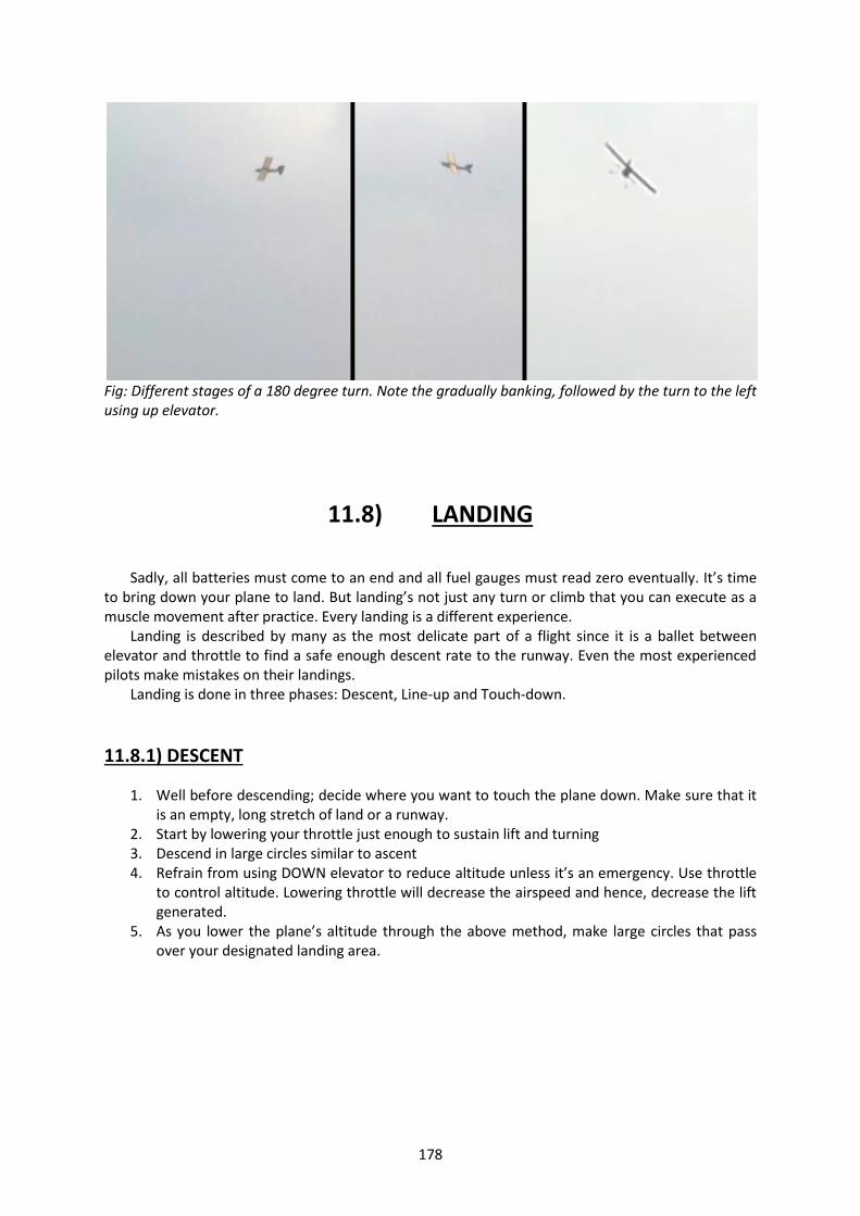
178
Fig: Different stages of a 180 degree turn. Note the gradually banking, followed by the turn to the left using up elevator.
11.8) LANDING
Sadly, all batteries must come to an end and all fuel gauges must read zero eventually. It’s time
to bring down your plane to land. But landing’s not just any turn or climb that you can execute as a muscle movement after practice. Every landing is a different experience.
Landing is described by many as the most delicate part of a flight since it is a ballet between elevator and throttle to find a safe enough descent rate to the runway. Even the most experienced pilots make mistakes on their landings.
Landing is done in three phases: Descent, Line-up and Touch-down.
11.8.1) DESCENT
1. Well before descending; decide where you want to touch the plane down. Make sure that it is an empty, long stretch of land or a runway.
2. Start by lowering your throttle just enough to sustain lift and turning 3. Descend in large circles similar to ascent 4. Refrain from using DOWN elevator to reduce altitude unless it’s an emergency. Use throttle
to control altitude. Lowering throttle will decrease the airspeed and hence, decrease the lift generated.
5. As you lower the plane’s altitude through the above method, make large circles that pass over your designated landing area.

179
Fig: The last wide turn before a landing. Even Though the plane lands towards the camera
Later, it takes a very wide left turn before landing
11.8.2) LINE-UP
1. Your plane must be in line with the runway for any landing. This is absolutely critical for a
safe landing 2. As you circle downwards, slow down your descent at a comfortable height above the
ground. Take the last circle at the same altitude This above height varies from plane to plane. Larger planes naturally require a larger final altitude before approach.
3. As you take your last circle, take it wider. This gives you a large enough length to line up your plane and descend into the touchdown.
4. Turn on your flaps now if you have any active. This will help you maintain the same lift at a much smaller airspeed
5. In this final stretch, USE YAW ONLY TO LINE UP YOUR PLANE. Your landing gear must be aligned and hence, you cannot use roll in your final moments other than to correct minor jostles.
6. Once you have lined up your plane, maintain that heading. 7. Slowly decrease your throttle and increase up elevator to put the plane into a controlled
descent. This does multiple things: a. It increases angle of attack, thus, providing more lift at the lower speed. b. It mildly pushes the nose up and the tail down, thus making sure that the landing
gear comfortably touch-down. 7. If you are unsure of your landing, now is the time to pull out. Since your nose is already up,
simply increasing throttle will generate lift and your plane will increase altitude. You can circle around and make a second pass at the runway.

180
Fig: Maintaining a positive angle of attack while reducing throttle and lining up the plane.
11.8.3) Descent
1. You are now lined up for touchdown. To gently bring you plane down to earth, you must have a gradual descent rate.
2. If you are not feeling confident, pull out of the landing and circle around for another run. 3. A good landing occurs in a very narrow space.
Too steep and your landing might turn into a crash. Too shallow and you might come in too fast.
4. Decrease throttle. This reduces the airspeed and hence, slowly brings down your plane. Note: Flaps have a natural tendency to bring down the nose of the plane. Hence, a constant up elevator it necessary during landing with or without flaps to keep the nose up.
5. Very gently descend at a uniform rate to the runway.
11.8.4) Rollout and Touchdown
Rollout: The phase of the landing barely 3 to 4 feet off the ground where the plane’s nose increases pitch to bring down the landing gear in the correct orientation.
181
1. The roll out is made to bring the plane into its final landing orientation. This might vary from plane to plane.
2. From here onwards, we will write two separate procedures for the two different types of landing gear
a. Tricycle b. Tail dragger
11.8.4.1) Tail dragger Gear
1. Here, the final angle of orientation of the plane is the construction angle of the plane, i.e, the angle that the X-axis of the plane makes with the horizontal when placed on level ground.
2. This is done to ensure that the plane touches down on all three wheels at the same time. However there are landings that this does not happen and the plane must be oriented differently.
3. The roll out is performed around 3 feet above the ground. (1 – 2 m span. Scale accordingly) 4. Increase angle of attack of the plane while simultaneously decreasing throttle to bring up the
nose but maintain the same descent rate. 5. If you decrease throttle too slowly, the plane will begin to slow down the descent and
possibly ascend. If you decrease throttle too rapidly, the plane will stall. Increase throttle or execute a failed approach.
6. If you increase angle of attack too rapidly, the plane will stall. If you increase angle of attack slowly, the plane will climb instead of descending.
7. Once the roll out has been completed, the plane must be touched down.
Landing Roll: This is the section of the landing from the point of touch down to when the plane comes to a complete halt.
1. Kill Throttle. 2. Once the plane has touched down, it is important to keep the tail down so that the tail
dragger can aid in steering. 3. Apply up elevator so that the tail gets pressed down. 4. However, too much up elevator and the plane may start bouncing. 5. Hold the plane’s heading straight.
Ground Roll: This dangerous occurrence is when the plane skids mildly due to cross wind or steering and this manages to lift one wing more than the other. This causes the plane to tilt and sway precariously, often resulting in a wing strike on the ground. IF A WING STARTS LIFTING, COUNTER IT WITH THE REQUIRED AILERON.
Speed Landings: Sometimes, landings are performed in crosswinds or under other strained power conditions that require the pilot to land at a higher speed than usual. This can have significant changes in the landing procedures of a tail dragger aircraft.
1. Bring down the aircraft in level flight attitude. Roll out is very small or even negligible. 2. Bring down the aircraft as slowly as possible. 3. After touching down, contrary to normal landings, apply DOWN elevator gently. This is done
to keep the tail up.

182
Note: If the plane is brought down too steeply, the tail will thud down rapidly on touch-down. If the tail is brought down too fast at a high enough speed, the plane will lift again and begin bouncing. In this case, PERFORM A FAILED APPROACH. The counter elevator to keep the tail up prevents this from happening unless and until the plane has lost enough speed for the tail to fall down on its own.
11.8.4.2) Tricycle Gear
1. Tricycle gear are much easier to land and often follow the same landing procedure even in terms of speed landings.
2. Perform the roll out until the 2 main wheels are the lowest part of the aircraft and are ready for touch-down. This angle varies for different planes.
3. Kill the throttle on touch down. 4. Once the touch-down has been made, apply DOWN elevator. This brings down the nose
wheel to the ground. HOLD the elevator there. 5. Hold the heading of the plane.
Fig: An instant before touch-down, this balsa glider shows a good positive angle of attack being maintained by the up elevator. This ensures a gradual descent rate.
11.9) SHUT-DOWN PROCEDURE
Remember that your aircraft is still live and must be shut down successfully to complete the flight. That was some pretty good flying.
1. Keep your throttle at zero. 2. Only after coming to a complete halt must you turn on throttle again to taxi towards the
required destination. 3. After reaching the required area, set throttle to zero. Wait for the prop to stop spinning.
Disconnect the plane’s batteries or power sources first. 4. Turn off your RC.

183
5. This completes the shutdown process for your aircraft. 6. Inspect you aircraft for wear-damage, landing damage, stress marks and any possible in-
flight damage that could have occurred. 7. Make note. And repair as soon as possible.
Well done.
11.10) EMERGENCY PROCEDURES
Not all flights can occur in a picture perfect manner. There are several things that can go wrong
at any point during a flight. The following guide will take you through the most basic problems encountered during any flight. Hopefully, these will give you the knowledge that you need to tackle more complicated problems.
11.10.1) Problems during take-off
A) Plane does not leave the ground even after reaching maximum throttle. Solution: Your plane is not getting enough lift to counter its own weight.
1. STOP YOUR PLANE IMMEDIATELY. 2. Your battery/fuel is low and hence, the engine cannot generate enough power. Batteries
deplete much more gradually than fuel. Therefore, they give you a much earlier reading of when the plane is about to lose power.
3. Your plane is too heavy for the lift you are generating. Reduce the weight of the plane without making changes to the thrust/lift systems.
4. Check your propeller. If it is on backwards, it will still generate thrust but it will be much less efficient.
5. Check if any structure on the plane is creating drag along the ground. 6. If none of the above is the problem, it’s time to rethink your design.
B) Plane stalls on take –off. Solution: Your plane has stalled because of a turbulent air flow over the wing. This is because of a very high angle of attack due to the steep climb you made after take-off.
1. Immediately increase your throttle to maximum and level the nose. After this, climb more steadily. Your nose may also drop below horizontal level so that gravity can aid in gaining airspeed but refrain from this and do not take your nose below level position.
2. If the angle of attack is too steep, then your plane will vertically stall and try to gain airspeed by falling. In case you are heading straight down, you will gain airspeed on your own. Pull back on the elevator stick to level the nose. From here, you may land or gain height.
3. If the stall is too steep and too close to the ground and the above don’t seem to work, face the consequences of a bad take-off. Start repairing.

184
11.10.2) Problems During Flight
A) Plane Stalls. Solution: Your plane has stalled because of a turbulent air flow over the wing. This is because of a very high angle of attack due to the steep climb you made. At this height, it is much easier to deal with a stall than close to the ground. This is because of a larger room for error.
1. Level your nose and increase throttle. 2. For worse cases, the nose must be pointed downwards so that gravity can also help the
plane in gaining airspeed. 3. The funda behind correcting a stall is to get air flowing over the wing properly again. This is
done simply by gaining air speed or reducing the angle of attack.
B) Control surface is not trimmed. Solution: Even though your control surfaces may have been at neutral position on the ground after trimming, changes in aerodynamics or CG location of the plane may cause the plane to move about one of the three axes. Hence, for steady flight, a plane must fly on its own without corrections from the control sticks. The necessary corrections can be done only in the air.
1. Use the control sticks to maintain a straight and level flight path. 2. Let go of all controls. 3. Note where and how the plane travels after that instant. Don’t let the plane drift too much. 4. Bring the plane back to level flight and get a partner to correct the trim levels while you hold
the plane level. 5. If no one is available, then perform the trim on your own. This may be difficult since you
have to hold the plane steady and change trim levels at the same time. Make sure you proceed in small increments/decrements.
6. Repeat the above steps until the point where the plane is able to maintain a level heading on its own.
C) Control surfaces are non-responsive in flight. Solution: Non-responsive control surfaces are an aircraft’s doom. The loss of control about one of the axes greatly decreases the maneuverability of the plane. The worst part is, control surfaces can become so because of several reasons. Some may be immediately recoverable, some may be permanently damaging. Either way, there are several methods by which the problem can be diagnosed. If you feel that the surfaces are becoming non-responsive, BRING THE PLANE BACK INTO RC RANGE IMMEDIATELY.
1. Low air-speed: Note that control surfaces need airflow over them to properly function. Otherwise they’re just annoying flapping appendages on a plane. When using torque rods for control surface, generally ailerons, (Refer BUILDING >>Control surfaces section) the control surface may deform, i.e., if the control surface is too large, one part of the surface might bend more than the other and hence, create unequal throws. The above problems may be solved by increasing the throttle. This increases the sensitivity of the control surfaces. Consider replacing torque rods by multiple servos instead.
2. Mechanism failure: Servos control the control surfaces by means of push rods. When these undergo large forces, they are prone to damage. The gears of the servo can break if the control surface pulls so hard that the centering changes. The push rods can bend and break in worse cases and must hence, be as short as possible. Mechanism failures cannot be controlled. Once they occur, only skilled pilots can land the plane safely. Refer to solution D) for further tips.

185
3. Range and interference: Planes are controlled by means of RC and receiver and hence, that they both communicate easily is of utmost importance. Like any wireless device, the RC and receiver have a maximum range distance that is built in and must be checked first with a range test. Range: if your plane flies out of range of your RC, there is nothing you can do about it. REDUCE THROTTLE TO ZERO In case the plane picks up signal later. Keep a close eye on the plane and hope that it lands in good enough shape for landing. Note down where your plane lands down so you can search for it and disconnect the battery as soon as possible. Interference: Interference can be caused by stray EM signals that interfere with the signals sent by the RC. These may be interpreted by the receiver as something different and can throw the plane wildly off course. STAY AWAY from electrical power lines or power houses. These have magnetic fields around them as well. Make sure your receiver antenna does not touch any metal parts of the body since these can act as receivers of signals also.
D) Thrust dies in flight. Solution: Motor failure can be caused by an extremely large number of problems that are beyond the scope of this section. The first order of priority is to land the plane safely at zero or minimal thrust.
1. The first step is to find out whether the problem is with the engine/motor or with the fuel/battery. In case you’re using batteries, run the throttle to full. If the throttle seems reduced, it’s time to land your plane. Make a slightly speeded descent and land as quickly as possible, following standard landing procedures. In case you’re using fuel, take a look at your timer occasionally to make sure you have enough fuel left. If fuel runs out, your engine will rapidly die without warning. If your motor suddenly dies on you, be prepared for the worst. One of two things could have happened.
2. The first is that your battery has totally run out and you can control nothing. This means that you no longer have control of the plane. Note where your plane crashes and repair the plane later.
3. The second is that something is interfering with your engine. Reduce throttle to zero and rapidly jolt the throttle to full to try to jump the engine into starting. In case this doesn’t work, make sure your seatbacks are in the upright positions and that your table trays are locked and that all passengers are braced for emergency landing.
4. As soon as your throttle dies, there is a limited amount of energy that you can spend to get to your landing spot. This energy is being constantly lost to friction with the air and hence, as you drop, you cannot climb back up to the same height and you permanently lose your maximum altitude.
5. Pick an empty space for landing as permissibly close to the plane as possible. 6. Descend as slowly as the plane lets you and line up with the runway as soon as possible. 7. Use UP ELEVATOR to keep the nose up and slow down the descent. 8. Hopefully, you should be able to bring down the plane to the designated landing spot with
the amount of energy that you initially had.

186
E) Aircraft breaks apart/gets damaged in flight. Solution: Structural damage can be because of aerodynamic stresses or improper construction. Either way, damage in the air is very difficult to recover from, more so if it occurs to the control surfaces. Structural damage also impairs the aerodynamic stability of the plane and hence, controlling it is like learning how to fly again.
1. Assess the damage: the most important thing to note is that none of your control surfaces are damaged. Damaged rudders and ailerons are fine. One can be used to naturally compensate for the other. It will make flying difficult but not impossible. Damaged elevators are more difficult to recover from. Elevators are the main surfaces that control altitude and hence, any damage makes a crash much more probable than with the aileron or rudder.
2. Aileron failure: this results in the inability to ROLL. However, if you remember from the AERODYNAMICS chapter, a plane yawing will cause a roll in the opposite direction and vice versa. This can be used to compensate for ailerons.
3. Rudder failure: this will not impede in flight capabilities as such but will severely hinder the descent and landing stages. To compensate for this, make your landing line-up very long. This will give you a large length to correct direction and descend using only ailerons. It might not be as precise as a rudder but it’s better than nothing.
4. Elevator failure: there are several ways to deal with this for different aircraft Using force vector from rudder to control descent a. Even though this goes against all your instincts, put the plane into a roll to an angle.
This angle is the maximum angle that the plane banks without losing altitude greatly. b. Now if you notice, the rudder is at an angle to the vertical and hence, a component
of its force is in the vertical also. Increase your throttle a little. c. Whichever direction the plane rolls, yaw opposite to that.. d. This helps you to control descent. If you want to gain altitude, simply level off the
plane and increase throttle a little. This will cause natural lift to increase the altitude of the plane.
e. Note, this method seriously impairs your turning and you must make very large turns.
Using lift from varying yaw a. If you need to gain altitude sharply, yaw your plane left and right at a normal speed. b. This rate of change of yaw must be quick enough that the plane to gain altitude but
must be slow enough for the plane to reach its maximum extent of yaw from the mean flight position.
c. As you yaw left, you roll right naturally. This results in your plane’s nose pointing at a positive angle. Now, as you yaw right again, the plane has a natural tendency to stabilize the roll. This stabilization results in a small gain in altitude.

187
Fig: Notice the roll angle of the plane and the opposing rudder. The rudder acts as a pseudo-elevator.
5. Wing breaks in half in flight.
Now what happens is that your plane has uneven lift. This starts lifting one side of the plane more than the other. This causes the plane to go into a rapid spiral that is almost totally irrecoverable from. The following set of instructions puts the plane into a controlled crash landing on its gear. Some assumptions have been made for this solution. i. The plane is at a high enough altitude. ii. All other control surfaces are functional. iii. There is a large amount of ground space to land.
a. Since lift is now unbalanced, engine torque plays a huge role in slowing down the plane’s
roll rate. Large engine torques can rotate the plane. At the same time, increasing throttle can increase lift over the wing and cause rotation about the X-axis.
b. Move the throttle stick to the appropriate throttle. This should be low enough that broken plane’s roll rate can be stopped using the remaining functional aileron.
c. The remaining wing will always roll in the direction of lift. i.e., Left wing will roll right and right wing will roll left.
d. Use maximum aileron to stop this. e. Also, you will need a constant up elevator and yaw to maintain a lift component. The
yaw should be in the same direction as the remaining wing, i.e., If left wing breaks, yaw left.
f. Do not change your throttle or control movements much AT ALL. The plane is highly unstable and will react violently to fast movements.
g. All of the above will control your descent rate. h. The flatter the wing, the more gradual the descent will be. i. Land the plane as level as you can. Crashes are unavoidable but a landing in these
conditions is highly commendable.

188
Note: None of the above methods are guaranteed to work. They depend on the plane’s orientation during the time of the failure, the wind direction, the pilot’s skill, the structure of the plane, etc. Be mentally prepared for a long night of repairs and reprimands.
Fig: Note the slightly deviated rudder. This landing will damage the engine. A higher amount of yaw is required to keep the plane’s nose away from the ground.
11.10.3) Problems During Landing
A) Plane comes in too steeply. Solution: If you have enough runway left, check the following procedure.
a. Increase throttle. This will make you move forward faster, increase lift and make the descent shallower.
b. Once this has been done, recalculate your descent rate, orientation and descend to the runway. If you do not have enough runway left, check the following
a. Increase throttle and climb steeply. If your plane does not generate enough lift, climb shallower.
b. But, climb beyond the height of surrounding objects and retake the descent again.
B) Landing gear does not descend. Solution: Gear failure can be caused by a jamming or total failure of the gear mechanism. The following will help you make a procedural landing without gear.
a. To make sure that your gear will not come down, put your pane through the following series of maneuvers. Make sure they are all at a comfortable altitude
b. Put the plane into a steep dive, and then pull up the plane to try to force out the landing gear.
c. Do the same with sharp turns, etc. d. If the landing gear still does not descend, then land anyways. e. If your engine is mounted on top of the wing, then you shouldn’t have much of a problem. f. If your propellers are going to hit the ground, switch off the throttle as soon as you land,
possibly an instant before. g. If any other sensitive mechanisms are at stake, plan your landing approach (angle and
speed) accordingly. h. The undersides of your fuselage or wing will be prone to damage. Inspect them after landing
thoroughly.

189
11.7.3) Crosswind Landings Every pilot’s worst night mare is a wind that doesn’t run straight at the nose of his airplane from the front. Headwinds are friendly. The farther away from the headwind, the more problematic it gets. The following section will explain in detail two different landing methods for executing crosswind landings. Crab Method The crab method employs the use of rudder to counter the wind and aileron work to keep the plane level.
1. Use rudder to change the heading of the plane into the heading of the wind to such an extent that the plane travels forward but is not pointed forward. This uses a component of thrust to counter the wind and another component to move the plane forward.
2. Use roll to hold the plan level. Upwind wing will have a tendancy to lift up. 3. Even if at maximum rudder and orientation straight into the wind, the plane is impossible to
control, abort the landing and wait for better conditions. 4. Use elevator to control descent rate. 5. An increased power landing might need to be executed. 6. Remove the crab JUST before touchdown. Change the heading of the plane straight along
the runway.
Wing-low Method The wing low method uses the exact opposite controls to stabilize the landing approach. It is generally preferred to the crab because it does not change the heading of the plane from the runway.
1. The upwind wing is lowered into the wind. 2. Counter yaw is given to hold the flight path straight. 3. Elevator is given to control descent rate. 4. Touchdown must be made ONLY ON THE UPWIND MAIN WHEEL. This is a very difficult
landing to make and the pilot must exercise extreme caution. Note that it is a high speed landing.
5. Hold the plane steady on the one main wheel until enough speed is lost to bring down the other main wheel also, and finally, the auxiliary tail or nose wheel.
6. Kill the throttle and stop the plane.
11.11) CRASH
Sigh, If only we didn’t have to write this section and all planes could happily land and take off. As difficult as it is to say, nobody’s perfect. And the same goes for planes too. Aeromodelling is an expensive hobby and it’s really disheartening when crashes occur. However, you must realize that it’s next to impossible to fly with a clean record. It’s ALRIGHT to crash now and then but not always. You’d expect the crash section to be short. Well, I mean, it’s a crash. What sort of checklist could a crash possibly have? Well, there’s another list of points for you to remember in case you know for sure that you’re going to crash. This is simply a Pre-crash checklist to reduce the after-damage.
1. Try your best to land the plane on its underside. This ensures that the landing gear, tail and undercarriage all bear the force of the impact and the engine comes to no harm.
2. The motor/engine is of utmost importance. DO NOT CRASH THE PLANE NOSE DOWN.

190
Several motors have been lost due to nose crashes bending their shafts and damaging their bearings.
3. Kill the throttle. Like, kill it ASAP. This makes sure that spinning propellers and engine blades do not still spin after impact and more importantly, do not injure any beings nearby.
4. If the crash is a controlled descent, try to pull the plane away from surrounding structures, personnel and animals. Make sure it crashes on an empty piece of land.
5. As soon as the plane crashes and throttle is reduced to zero, run like a sissy to the wreckage. Post-crash, you want to get to the wreckage as soon as possible. Several things could have gone wrong in flight but the first thing to ensure is that nothing more goes wrong. The additional list could involve fires, short circuits, personnel injury, etc. etc.
1. BATTERY – As soon as you get to the crash site, search for the battery and disconnect it. 2. FUEL – Stop the fuel supply from the tank to the engine and disconnect the tank. 3. Stop any live electricity/combustion processes as soon as possible. 4. If the plane lands in a puddle, remove the plane from it and quickly detach any electronics
that have gotten wet and leave them in a dry place to dry out. 5. Make sure that you have every single part of the plane. This includes little breakages of the
materials, pieces of metal or glass, push rods, rubber bands, etc. leave NOTHING behind. There was once an instance where after the crash; the rudder was nowhere to be found! Later it was determined that the rudder had broken off in mid flight due to improper gluing.
6. If the plane is still in sound condition after the crash visibly, Check all the electronics systems and do a structural integrity test as mentioned in the early stages of this manual.
11.12) CONCLUSION
Well, that’s about it folks. We sincerely hope that your flying experience is enjoyable and safe. And I’m trying my best not to sound like an airhostess while saying that. Always remember, practice makes perfect as long as you repair all of your own planes. Before you can become a professional RC pilot who does stalls, hovers, harriers, Cuban eights, torque rolls and what not, you must learn first how to land, fly and take off. A good idea might be to start out with a 3 channel glider with dihedrals. These are extremely stable planes and cannot over roll very easily. They have only rudders and elevators and are often, the first planes that we fly. Listen very carefully to your instructors and if you don’t have an instructor, read the instructions at least thrice before proceeding with the action. Sigh, you should hear your seniors rant on about instructions. This is handbook is nothing compared to a year full of flying.

191
CHAPTER 12
A CASE STUDY OF THE
Il’ NOSTRO

192
12.1) INTRODUCTION
Congratulations! You have officially finished reading all the material that the handbook has
to offer! You can’t wait to start using your new found knowledge can you?
Welcome to the final chapter of the handbook. Before proceeding with the design and
building of your own plane, we thought we’d let you know what we did for a very famous plane
design that was used for the glider workshop of the first semester of the academic year 2012-13.
This chapter will bring out every aspect of designing, building and flying that you have learnt
so far with the help of a well-known example, the Il’Nostro glider and show how all the concepts
that we’ve used so far apply to this aircraft. We will be covering the following elements of the
process in detail:
1. Designing and brainstorming.
2. Materials and tools required.
3. Calculating electronics.
4. Putting it all together.
5. Maiden test flight.
6. Conclusion

193
12.2) DESIGNING AND BRAINSTORMING
As with every adventurous proposal, the entire process begins with a session of good old
brainstorming. A brain storming session is extremely important to determine the overall
characteristics of the plane. A group of individuals come together and discuss all aspects of the plane
and its construction and flight procedures. The following process is followed for brainstorming.
Step 1: Plane type and characteristics
The first thing to decide is what kind of plane you want to build. The Il’Nostro was decided to
be a glider since they are the simplest to build and are also the most stable planes. Gliders are
generally suggested for beginners. We decided that the plane should be a medium speed powered
glider that could perform basic tricks such as loops, rolls and maybe even inverted flight for short
durations.
Step 2: Physical structure and dimensions
The next step is to ascertain the physical form of the plane. As it was a glider, the wing was
planned to be a high aspect ratio wing with very high lift. The fuselage was determined to be a box
fuselage that would be covered by a layer inside within which the electronics would be housed. We
also decided that the airfoil would be an airfoil that would generate massive amounts of lift even at
low speeds. The engine was to be mounted inside a cavity called the cowl. The stabilizers were
planned to be very large in comparison to the plane for that extra amount of stability. Finally, the
dimensions were determined to be as follows:
Wingspan : 1m central spar with 20cm long dihedrals at either end of wing at an angle of 20
degrees. Total length of 1.2m.
Fuselage length : Roughly 1.1m depending on construction.
Airfoil : High-lift
Control surface : 25% of Stabilizer.
Holes would have to later be drilled into the wooden internal structure of the plane to
reduce the weight of the plane.
Step 3: Design specifics
Finally, we brainstormed the finer details of the entire arrangement with respect to what
materials would be potentially available to us. For example, the airfoil was intended to be very high
lift. This would be very easily made with a properly shaped wing. However, making the airfoil with
respect to the very easily available material coroplast would make the leading sharp and hence,
make the airfoil very prone to stalling.
The internal framework of the plane was also determined at this point to be 2 spars
separated at one end by about 3 inches (for the motor) and conjoined at the other end. The length
and extent of curvature of each of these rods would determine the fuselage length

194
12.3) MATERIALS AND TOOLS REQUIRED
Now that we’ve finalized the physical aspects of our design, it’s time to determine what
materials we’ll require for it.
Step 1: Wing and dihedral materials
We decided that the wing and dihedrals were going to be made of coroplast that would be
internally supported by a wooden spar. The folding of the coroplast over the central spar would
shape the airfoil. Hence, the required materials are coroplast (2mm), a lot of CA glue, a 1m wooden
spar for the main shaft and two 20cm pieces of the same wooden spar for the dihedrals. The
required tool was a very sharp cutting blade.
Step 2: Fuselage
The fuselage was determined to be a box fuselage. Hence, it would also require some sort of
internal structure. This internal structure would be given by two wooden spars that would be
attached in an almost parallel manner. The front ends would be attached to a wooden plate for the
motor mount and the back ends would be attached together to taper down the fuselage to a point.
The covering of the frame work was to be given by a trapezoidal piece of coroplast wrapped
around the entire fuselage. The trapezoid would ensure a smooth taper from motor to tail tip. A
little extra coro was left in front of the motor plate and going around it to structure a cowl.
Hence the materials required are 3mm coroplast, 2 wooden spars, 1 wooden plate, 2
wooden blocks (for internal support at points along the length of the fuse) 1 drill for drilling holes to
attach all of these together, appropriate screws and screwdrivers, cutting blade, etc.
Step 3: Empennage and Undercarriage
The empennage was also decided to be made of coroplast since it is very easy to cut hinges
in coroplast. The control surfaces were designed to be 2 inches large and being around 25% of the
stabilizer’s area. There would be no mixing as this was to be a trainer aircraft for beginner and we
wanted to keep it as simple as possible. A standard tail design was used with one vertical stabilizer
and a perpendicular horizontal stabilizer at the base of the vertical one.
The undercarriage was determined to be a tail dragger as these are generally required for
the propeller clearance of planes with nose mounted prop engines. Foam tires would be used in the
process as they are the most easily available. They would be fastened to the undercarriage through
one of the wooden blocks attached to the frames with the help of flexible metal rods.
Hence the materials needed would be coroplast, a cutting blade, some CA glue and a cutting
blade.
Now we’ve determined what all is necessary for building the frame work of the aircraft.

195
12.4) CALCULATING ELECTRONICS
Now that we have determined all that is required for building an entire aircraft, now we
must determine how the aircraft will be powered and controlled. The next step is to calculate the
electronics required for the aircraft. For explaining this stage of the process, we will use the help of
the procedure that has been described under chapter 7 >> Putting it all together.
1. First, we estimated the All Up Weight (AUW) of the aircraft to be around 1.2 to 1.5 kgs from
previous experience. The final weight came up to be around 1.1 kgs which tallied well with
our estimate.
2. Next, from the watts per pound algorithm, we decided that our plane should be slightly
overpowered as is the case with all trainer gliders. This led to a motor rating of around 300
watts. The motor we actually bought was rated to be around 350W. This was because we
thought the plane would turn out to be heavier than it was. The motor also had an S rating
of 2-3S.
3. Now that we had the motor’s rating, we looked at its maximum current draw which turned
out to be 27A. Hence, we picked an ESC that had a rating of 40A and an S-rating of 2-5S.
4. Now that we’d decided the ESC’s current and voltage ratings, it was time to pick the battery.
We selected a 2200mAh battery at a rating of 25C sustained discharge. This would mean
that the current drawn would 55 Amps for roughly 3 minutes. Since the current we would be
using would not exceed 20A, the run time increased to nearly 10 to 15 minutes.
5. As was recommended with the motor, we bought a 10x5E propeller.
6. Servos were purchased with metal gears that were very resistant to wear and tear.
We placed these orders in bulk for all the teams present at the workshop.
12.5) PUTTING IT ALL TOGETHER
Servo mounting: 2 servos were used for the tail and 2 were used for the ailerons. The tail servos
were mounted with the help of double tape and cable ties and the horns were positioned
appropriately. Care was taken to ensure that both servos could go to their full maximum throws
without obstructions. The two aileron servos were mounted at equal distances from the fuselage. A
soldered self-made y-cable was used to connect both aileron servos.
Small slits were made along the length of the fuse wherever it was necessary for the servo
cables to come inside or outside of the aircraft’s fuselage.
Motor mounting: The motor was mounted to the base plate on the front of the fuselage with the
help of drilled holes and screws. It was positioned in such a way that the thrust vector was parallel to
the fuse perfectly. Washers were used to adjust the orientation of the motor to achieve this.

196
Wheel mounting: Landing gear wheels made of foam
were used on the plane. They were slotted onto the rods
under the aircraft and were fastened into place with the
help of some small lengths of thread and CA glue. The
reaction created a mass that held fast and stopped the
wheel from slipping out of the landing gear rod.
Wing mounting: The final step of the construction
process was the mounting of the wing using rope. The
extension of the y-cable and the ends of two ropes
passing through the wing vertically were passed through the fuselage’s bottom surface. They were
pulled from under until the wing sat on the fuselage of the plane. Pieces of double tape were used to
temporarily hold the wing in place above the fuselage. Once the wing was taped, the tying began.
The rope was crossed over and under the wing and across it also. Even number of cross-
overs was made on either side. Once enough of the rope was used up, the loose ends were tied
together tightly.
Now, your construction is finally complete!
12.6) MAIDEN TEST FLIGHT
Now that the plane has been constructed, it is time to test whether it will fulfil the purpose
for which it was made. Test flights are tricky because one has no idea how the plane will actually fly
and the only guesses that can be made are based on the construction and design of the plane.
Firstly, before proceeding with a study of the test flight of the Il’Nostro, some points must be kept in
mind regarding test flights.
1. Be prepared for anything to happen. Keep someone close by if possible to help you with
trimming the aircraft in case it’s too unstable.
2. For a test flight, be extra careful of pre-flight checks. Perform them thoroughly and inspect
each part at least twice before test flying.
3. If a flaw is spotted, DO NOT continue with the test flight and wait until it has been rectified.
4. After performing the flight checks thoroughly, place the aircraft on a clear stretch of runway
and facing into the wind.
5. Throttle to FULL on take-off as you do not know how much the plane requires for take-off.
6. Gain altitude as quickly as possible without putting the plane into a stall. This must be done
while keeping the plane level.
7. Once altitude has been gained, perform trim checks.
8. Note all the necessary characteristics of the plane’s flight. Take the plane around for one or
two rounds to get a feel for the plane.
9. Land the plane gradually after finding that sweet spot between elevator and throttle that
results in a gradual descent rate.

197
The test flight of the Il’Nostro was performed keeping all of the above points in mind. The
following were observed after the test flights of several of the aircraft.
1. The aircraft took off at around 60-70% throttle of its own accord without the need of an
elevator input.
2. Small amounts of trim were performed on all the aircraft flown. However, some aircraft, due
to the asymmetry of the wing, generated more lift on one side than the other and hence,
resulted in non-trimmable amounts of roll. Servos had to be re-centered after landing to
account for the counter roll.
3. The aircraft stalls in a tailwind turn. This is characteristic of all aircraft.
4. Landing the aircraft is relatively easy due to the high amount of lift generated by the airfoil.
The aircraft is also more prone to land in a two point, level-flight attitude than a three point
touch-down.
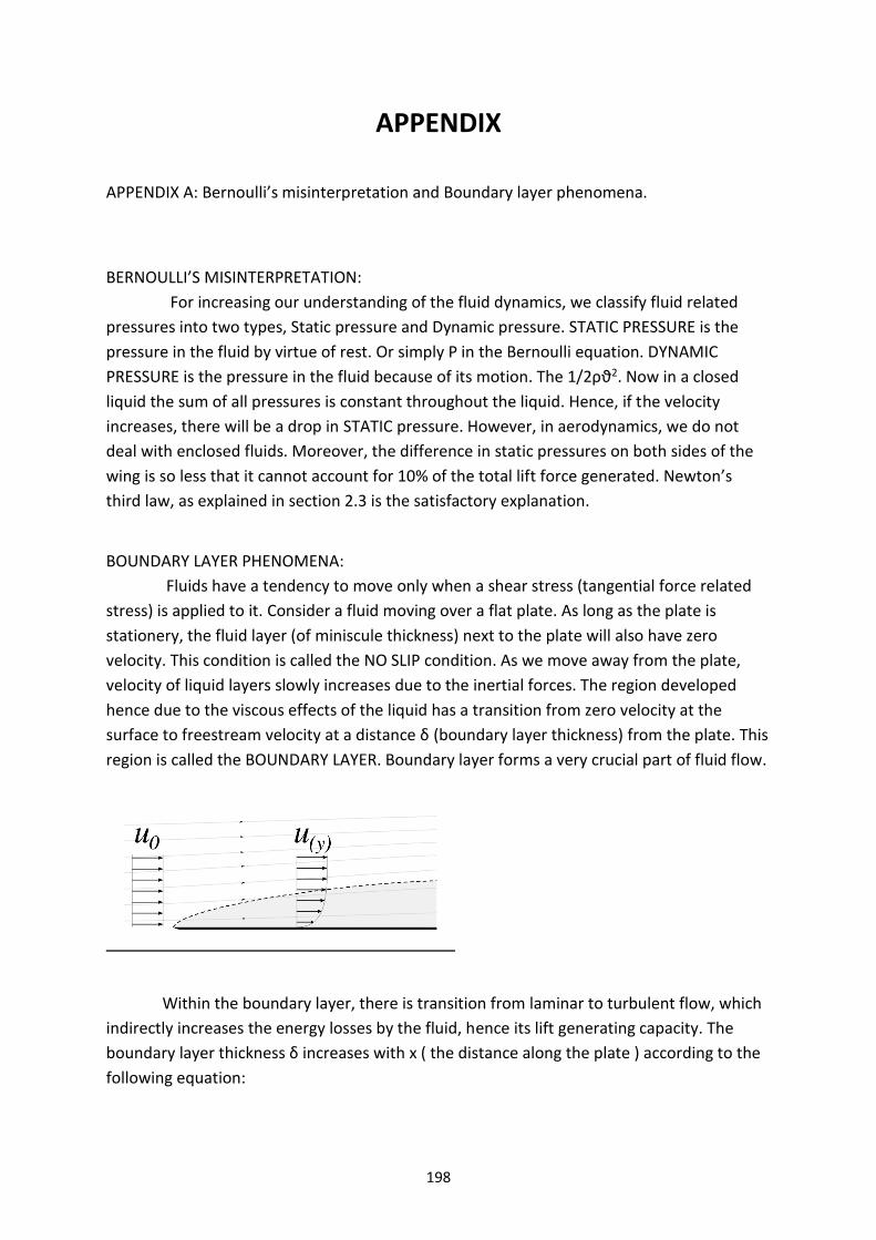
198
APPENDIX
APPENDIX A: Bernoulli’s misinterpretation and Boundary layer phenomena.
BERNOULLI’S MISINTERPRETATION:
For increasing our understanding of the fluid dynamics, we classify fluid related
pressures into two types, Static pressure and Dynamic pressure. STATIC PRESSURE is the
pressure in the fluid by virtue of rest. Or simply P in the Bernoulli equation. DYNAMIC
PRESSURE is the pressure in the fluid because of its motion. The 1/2ρϑ2. Now in a closed
liquid the sum of all pressures is constant throughout the liquid. Hence, if the velocity
increases, there will be a drop in STATIC pressure. However, in aerodynamics, we do not
deal with enclosed fluids. Moreover, the difference in static pressures on both sides of the
wing is so less that it cannot account for 10% of the total lift force generated. Newton’s
third law, as explained in section 2.3 is the satisfactory explanation.
BOUNDARY LAYER PHENOMENA:
Fluids have a tendency to move only when a shear stress (tangential force related
stress) is applied to it. Consider a fluid moving over a flat plate. As long as the plate is
stationery, the fluid layer (of miniscule thickness) next to the plate will also have zero
velocity. This condition is called the NO SLIP condition. As we move away from the plate,
velocity of liquid layers slowly increases due to the inertial forces. The region developed
hence due to the viscous effects of the liquid has a transition from zero velocity at the
surface to freestream velocity at a distance δ (boundary layer thickness) from the plate. This
region is called the BOUNDARY LAYER. Boundary layer forms a very crucial part of fluid flow.
Within the boundary layer, there is transition from laminar to turbulent flow, which
indirectly increases the energy losses by the fluid, hence its lift generating capacity. The
boundary layer thickness δ increases with x ( the distance along the plate ) according to the
following equation:
199
δ/x = 4.91/(Re)1/2
where Re = ρvx/µ and laminar flow is present (Re<105)
APPENDIX B.1
Airfoil properties.
General Properties:
DATABASE FOR AIRFOILS:
http://www.ae.illinois.edu/m-selig/ads/coord_database.html
http://airfoiltools.com/
APPENDIX B.2
Common airfoils.
The NACA airfoils are airfoil shapes for aircraft wings developed by the National
Advisory Committee for Aeronautics (NACA). The shape of the NACA airfoils is described
using a series of digits following the word "NACA."
1. First digit describing maximum camber as percentage of the chord.
2. Second digit describing the distance of maximum camber from the airfoil leading edge in
tens of percents of the chord.
3. Last two digits describing maximum thickness of the airfoil as percent of the chord
APPENDIX B.3
Characteristics of a good general purpose (high carrier) airfoil include:
1. High maximum lift coefficient.
2. Low minimum drag coefficient.
3. Best Lift/Drag ratio.
4. Sufficient thickness and depth for spars and mechanical and electrical
structures inside the wing rather than keeping them outside and increasing drag.
5. Least possible movement of Clift with angle of attack.
**These criteria would change depending on the type of plane the airfoil would be used on.

200
APPENDIX C : Special plane configurations and types.
C.1: Canard configuration
Canard configuration involves the placement of the tail plane in front of the main
wing. The front wing (tail plane) is at a higher angle of attack than the main wing (2 or 3
degrees higher). This feature gives high amount of longitudinal stability to the aircraft.
A. if the plane pitches up, then the front wing would be at a much higher angle of attack
than the main wing. The front wing would stall first, resulting in loss of lift and pitch down
motion of the plane.
B. if the plane pitches down, the front wing would be at a higher angle of attack than the
main wing, generating more pitch moment. Hence a resulting pitch up motion of the plane.
C.2: High wing aircraft
High wing aircraft ensures a relatively lower centre of gravity as compared to a
low wing aircraft. When a plane rolls, the sideslip produced results in an equal force on the
wing in an opposite direction. Due to lower position of the CG the stabilizing moment Is
much greater in a high wing aircraft, hence more roll stability. Hence, as shown by the
picture, a high wing aircraft requires less dihedrals than a low wing aircraft.
The world’s heaviest operational plane, the Antonov 225, has a high wing, hence it
compromises for the dynamic stability/instability created by the anhedrals.

201
C.3 : Flying Wings: These fuselages are almost non-existent and are very uncertain. In a flying wing,
the fuselage is built into the wing. Theoretically, this is the most aerodynamically efficient design as
it involves only a wing.
Advantage: Highly efficient aerodynamically.
Disadvantage: Difficult to build. Absence of stabilizers makes the aircraft highly unstable and
difficult to control without the help of computers/sensors. Yaw unstable. Refer to the
chapter SPECIAL AIRCRAFT.

202
CONCLUDING THE HANDBOOK
Hearty congratulations to you for completing your reading of the Aerodynamics Handbook
by Aero BPGC. We sincerely hope that the journey has been very fruitful to you and that you have
acquired vast amounts of knowledge along the way. This handbook, along with your experience of
flying and building with the club, will help to fuel your passion in aerodynamics and will also help to
serve as a platform for further pursuits.
Further pursuits, where can you go to from here? What’s left after learning the
fundamentals of aerodynamics, design, building and flying? Well, cheesy as it sounds, the sky is the
limit!
Several of our members have begun to specialize in their own fields in RC modeling. Several
members have gone straight into building and designing and are currently coming out with new
designs every single month, week and day. Other members have gone into the specialization of their
flying skills. They’ve begun to explore the boundary capabilities of a plane and push all of our new
designs to the limit while coming up with new challenges to fly. Other students have gone entirely
into the electronic aspect of flying and are planning projects such as hands-free flying, unmanned
aerial vehicles, etc. As you would have learnt from this book, there are several dozens of things that
you could focus on and become a professional at.
On the part of the Aerodynamics Club of BPGC, we’ve given you a broad foundation for RC
flying. The amount of knowledge we’ve provided you is a good start for your aero modeling hobby.
We’ve also provided you with the materials and the technical know-how on how to use them. The
only thing limiting you is your imagination and your passion.
That winds up the handbook. Don’t forget that the handbook is NEVER COMPLETE. It is a
representation of the knowledge and experience of the club and hence, is always growing in size and
content. Don’t hesitate to add your contribution to the handbook and teach future generations a
thing or two. If you find a mistake in the handbook factually, don’t hesitate to point it out! It’s
critically important that we deliver the correct knowledge to thirsty minds.
Do remember that we do not have a single aim at which we are focused towards or a single
contest that we aim to win. We simply fly and build because we love doing so and it makes us happy
doing so. If accolades to come our way in the process, we’re happy! We sincerely hope you have a
nice tenure at the club and come up with many successful projects.
The authors feel that criticism is an integral part of reading, and thus, feel free to contact
them for anything.