AEROCARB $10.00 OWNERS MANUAL - AeroConversions · 1. Push the throttle cable's knob all the way in...
27
AEROCARB OWNERS MANUAL A Product of Sonex Aircraft, LLC $10.00 Rev I 03/14/13 Applies "Internal Pull" AeroCarbs as well as previous models
Transcript of AEROCARB $10.00 OWNERS MANUAL - AeroConversions · 1. Push the throttle cable's knob all the way in...

AEROCARB OWNERS MANUAL
A Product of Sonex Aircraft, LLC
$10.00
Rev I 03/14/13 Applies "Internal Pull" AeroCarbs as well as previous models

2
AeroCarbTM Owners Manual
Sonex Aircraft, LLC Rev I 03/13 © 2013 All Rights Reserved.
Table of Contents .................................................2Disclaimer and Limited Warranty ............................................ 2Table of Contents ..................................................................... 2
Specifications .......................................................3Overview and Features ............................................................ 3Carburetor Size recommendations ........................................... 3Dimensions .............................................................................. 3
Fuel System Overview .........................................4Fuel Delivery Systems ............................................................. 4
AeroCarb Installation ...........................................5Mounting the Carburetor .......................................................... 5Install a Friction Lock or Push/Pull Throttle Cable ................. 6Installing a "Pull" Throttle Cable for Reversing Throttle Quadrants ................................................................... 8Install the Mixture Cable ....................................................... 14Install the Fuel Line ............................................................... 16Intake Air, Air Filter, and Carburetor Heat Installation ......... 16Installing the Optional AeroConversions Air Filter or Intake Flange Adapter ........................................................ 17
Tuning Procedures .............................................18For Best Results... ............................................................. 18How the AeroCarb Works ...................................................... 18Mixture and Idle Adjustments ................................................ 19Changing the Mixture Needle ................................................ 20Adjusting the Idle Speed Stop Screw ..................................... 21Adjusting the "Full Throttle" Position of the Throttle Slide .... 22When is it in Tune? ................................................................ 23Compensating for Seasonal Changes ..................................... 23Tuning the AeroCarb - Step by Step ...................................... 24
Operating Checklists..........................................25
Troubleshooting .................................................26
Parts List .............................................................27
TABLE of CONTENTS
This guide was written to help you achieve a depend-able installation and outstanding performance from your AeroConversions AeroCarb. Properly installed and tuned, the AeroCarb has gained a reputation for increasing power and reducing fuel consumption on a broad range of aircraft and auto-conversion engines.
© 2013 Sonex Aircraft LLC. All Rights Reserved. The information disclosed herein is the property of the originator who reserves all pat-ent, design, proprietary, manufacturing, use and sales rights thereto, except for the rights expressly granted to others. This document shall not be reproduced nor shall the information contained within be used by or disclosed to others except as expressly authorized by the originator.
AeroCarbTM is the Trade Mark of Sonex Aircraft LLC
511 Aviation Road Oshkosh, WI 54902Phone (920) 231-8297 fax (920) 426-8333
[email protected] www.aeroconversions.comDistributed Worldwide by: Sonex Aircraft, LLC.
Disclaimer and Limited WarrantySonex Aircraft, LLC, makes every effort to assure that AeroCarb meets high quality and durability standards, and warrants to the original purchaser that this product is free of defects in material and workmanship for the period of one year from the date of purchase. This warranty does not apply to damage due directly or indirectly to misuse, abuse, negli-gence or accidents, repairs or alteration out side our facilities or lack of maintenance. Due to the experimental nature of the AeroCarb, the end user is solely responsible for determining AeroCarb's suitability, installation and use. Sonex Aircraft, LLC, will in no event be liable for death, injuries to person or property, or incidental, contingent, special, or consequential damages arising from use of our product.Important:By opening the package you agree to accept all responsibility for the use of this product and accept all such printed terms.
Not TSO'd for Certified Aircraft
A Product Line of Sonex Aircraft, LLC.
3
AeroCarbTM Owners Manual
Sonex Aircraft, LLC Rev I 03/13 © 2013 All Rights Reserved.
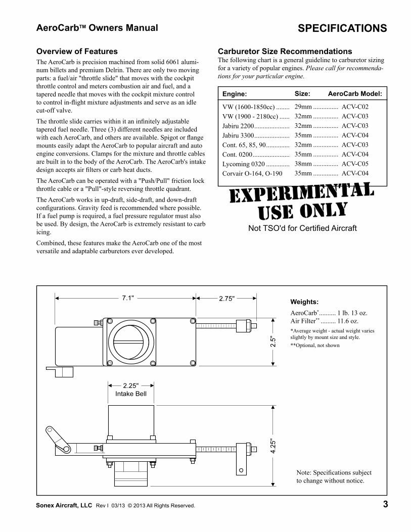
Overview of Features Carburetor Size RecommendationsThe following chart is a general guideline to carburetor sizing for a variety of popular engines. Please call for recommenda-tions for your particular engine.
Not TSO'd for Certified Aircraft
Engine:
VW (1600-1850cc) ........VW (1900 - 2180cc) ......Jabiru 2200 .....................Jabiru 3300 .....................Cont. 65, 85, 90 ..............Cont. 0200 ......................Lycoming 0320 ..............Corvair O-164, O-190
Size:
29mm ...............32mm ...............32mm ...............35mm ...............32mm ...............35mm ...............38mm ...............35mm ...............
AeroCarb Model:
ACV-C02ACV-C03ACV-C03ACV-C04ACV-C03ACV-C04ACV-C05ACV-C04
SPECIFICATIONS
Weights:AeroCarb* .......... 1 lb. 13 oz. Air Filter** ......... 11.6 oz.*Average weight - actual weight varies slightly by mount size and style. **Optional, not shown
The AeroCarb is precision machined from solid 6061 alumi-num billets and premium Delrin. There are only two moving parts: a fuel/air "throttle slide" that moves with the cockpit throttle control and meters combustion air and fuel, and a tapered needle that moves with the cockpit mixture control to control in-flight mixture adjustments and serve as an idle cut-off valve.The throttle slide carries within it an infinitely adjustable tapered fuel needle. Three (3) different needles are included with each AeroCarb, and others are available. Spigot or flange mounts easily adapt the AeroCarb to popular aircraft and auto engine conversions. Clamps for the mixture and throttle cables are built in to the body of the AeroCarb. The AeroCarb's intake design accepts air filters or carb heat ducts.The AeroCarb can be operated with a "Push/Pull" friction lock throttle cable or a "Pull"-style reversing throttle quadrant.The AeroCarb works in up-draft, side-draft, and down-draft configurations. Gravity feed is recommended where possible. If a fuel pump is required, a fuel pressure regulator must also be used. By design, the AeroCarb is extremely resistant to carb icing.Combined, these features make the AeroCarb one of the most versatile and adaptable carburetors ever developed.
Note: Specifications subject to change without notice.

4
AeroCarbTM Owners Manual
Sonex Aircraft, LLC Rev I 03/13 © 2013 All Rights Reserved.
FUEL SYSTEM OVERVIEW
Fuel Delivery SystemsMost fuel systems can be made to work with the AeroCarb's floatless design. If you have a system not represented on this page, please call for advice.IMPORTANT: The fuel system must be able to deliver 1.5 times the engine's required fuel flow at full throttle.Gravity Feed SystemA gravity feed system is by far the safest and most reliable. The AeroCarb requires very little head pressure to operate effectively. For this system to be effective, the fuel tank outlet must be higher than all the other components of the fuel deliv-ery system in a tail low (climb) configuration or fuel flow may be disrupted.
Return Line SystemIn a fuel return system a fuel line "T" is installed between the regulator and the AeroCarb with a return line to the tank. This will supply fuel to the AeroCarb without excessive pressure. Excess fuel returns to the tank.
Fuel Pump and Regulator SystemIf your aircraft requires a fuel pump (i.e.: for wing tanks or pusher engines) a fuel pressure regulator must also be installed to limit fuel pressure to about 1 to 2 psi. A Purolator Pro-Fuel Regulator, Model #54 (or equal), has been found to be effec-tive for these installations.
Header Tank SystemPumping fuel from the main tank(s) to a small header tank mounted above the carb will provide gravity feed to the AeroCarb. A return line from the header to the main tank(s) is required so excess fuel can return to the main tank without a build-up of pressure. This type of system assures some reserve fuel in the event the fuel pump fails, and eliminates the need for a fuel regulator.
The gravity feed system.
The fuel pump / regulator system.
The return line system.
The header tank system.

5
AeroCarbTM Owners Manual
Sonex Aircraft, LLC Rev I 03/13 © 2013 All Rights Reserved.
AEROCARB INSTALLATION
Section ContentsMounting the AeroCarb ........................................................... 5Install a Push/Pull (Friction Lock) Throttle Cable ................... 6Install a Pull (Reversing Throttle Quadrant) Throttle .............. 8Installing the Mixture Cable .................................................. 14Install the Fuel Line ............................................................... 16 Intake Air, Air Filter, and Carburetor Heat Installation ......... 16The optional AeroConversions Air Filter and Intake Flange Adapter ............................................................ 17
Mounting the AeroCarbThe ideal mounting position for an AeroCarb is in the updraft configuration, as low as possible, to assure constant gravity fuel flow even in extreme nose high attitudes. However, the AeroCarb functions well in any position.WARNING: Fire hazard. Do not install the AeroCarb where dripping fuel can contact hot exhaust or electrical equipment. If necessary, install a drip pan to catch/deflect dripping fuel. Always close the mixture shut-off valve and fuel valve when the engine is off.IMPORTANT: If the cockpit mixture control is not pulled to the Idle/Cut-off position when the engine is off, fuel will continue to flow through the carburetor. This may fill the AeroCarb/intake causing engine flooding or spill-over, which is a fire hazard.Note: If you are using an optional AeroConversions Air Filter or Intake Flange Adapter it is easier to install these before mounting the Aerocarb to the intake manifold. See page 17.
Spigot Mounted AeroCarbThe outside diameter of the AeroCarb's spigot must match the inside diameter of the engine's hose mount. If you are replacing a carburetor, the existing hose mount can mostly likely be reused after inspection. Replace the hose if it shows signs of deterioration.If you do not have a hose, we recommend NAPA fuel tank filler hose (or equivalent fuel proof hose) of the proper diam-eter. Do not use radiator hose.Attach the hose and AeroCarb to the engine with two stainless steel hose clamps. Updraft and sidedraft installations must be further secured with safety wire to the intake manifold, as shown in the photo below.
This spigot-mounted AeroCarb is also safety wired to the intake manifold for further security.
This sample adapter plate has 4 holes matched to the AeroCarb's flange, and 2 matched to the 2-hole intake mani-fold. The center hole matches the inside diameter of the intake bell.
Flange Mounted AeroCarbA flange mounted AeroCarb will bolt directly to a four-hole Continental or Lycoming intake manifold. Use a standard gasket or a small amount of gasket-maker when mating the AeroCarb to the manifold.To mount a standard four-hole flange to a two-hole manifold, fabricate an adapter plate from 1/4" to 3/8" thick 6061-T6 aluminum flat stock. Use standard gaskets or a small amount of gasket-maker on both sides of the adapter when mating the AeroCarb to the manifold.

6
AeroCarbTM Owners Manual
Sonex Aircraft, LLC Rev I 03/13 © 2013 All Rights Reserved.
Installing a Friction Lock or Push/Pull Throttle CableIMPORTANT: This installation requires a push-pull throttle cable with a threaded end and friction or vernier lock. Do not use a wire-only throttle cable as you will experience bind-ing.
Materials Needed:qFemale Rod End Bearing (Wick's p/n MW-3 or equivalent )qAN960-1032 Washerq10-32 Jam NutqAN3-6A BoltqThrottle Cable, Threaded End, 10-32 Thread
Cable RoutingThe throttle cable must be routed so it does not have any sharp bends. A grommet must be used where the throttle cable passes through the firewall.CAUTION: Do not allow the throttle cable to come in con-tact with the battery terminals.CAUTION: Do not allow the throttle cable to come in con-tact with the exhaust pipes.
Connecting a Threaded-End Throttle Cable to the CarburetorNote: If you are using the optional throttle arm, refer to the instructions on page 8. 1. Push the throttle cable's knob all the way in ("full throt-
tle") and lock it in place with the friction lock. 2. Loosen the throttle cable clamp on the carburetor and
remove the split sleeve. See photo, next column.
Wire Cable - DO NOT USE!
Threaded End - REQUIRED!
The AeroCarb requires the use of a threaded-end throttle cable when using a push/pull throttle cable, a wire-end cable will cause binding.
The throttle cable is passed through the split sleeve which is held in place by the throttle cable clamp. The black dust shield must be removed to install the throttle cable in the sleeve.
Split Sleeve
Dust Shield
Throttle Cable Clamp
Throttle Cable
4. Slide the throttle cable into the split sleeve. It may be necessary to ream the inside diameter of the split sleeve if the throttle cable cannot be installed. An "F"-sized drill bit works well (.254"). Do not tighten the throttle cable clamp at this time.
Note: Throttle cables up to .375" diameter may be used. For large diameter throttle cables, remove the split sleeve.
If necessary, the throttle arm block can be repositioned on the threaded rod, as seen in these photos. This allows some versa-tility in fine-tuning the throttle linkage.
Lock Nut
Throttle Arm Block
Threaded Rod
AEROCARB INSTALLATION
5. Re-install the black dust shield on the throttle cable. 6. Loosen the lock nut which locks the throttle arm block in
position.
3. Remove the black dust shield from the throttle cable.
7
AeroCarbTM Owners Manual
Sonex Aircraft, LLC Rev I 03/13 © 2013 All Rights Reserved.
AEROCARB INSTALLATION
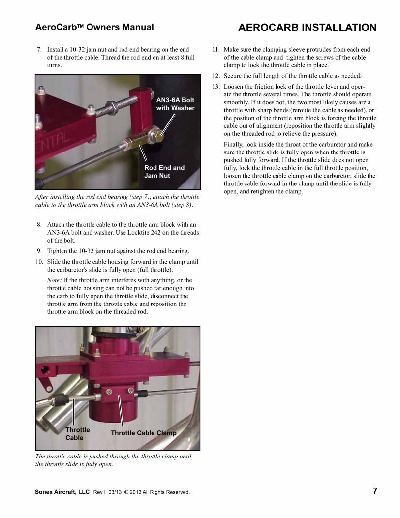
After installing the rod end bearing (step 7), attach the throttle cable to the throttle arm block with an AN3-6A bolt (step 8).
Rod End and Jam Nut
7. Install a 10-32 jam nut and rod end bearing on the end of the throttle cable. Thread the rod end on at least 8 full turns.
8. Attach the throttle cable to the throttle arm block with an AN3-6A bolt and washer. Use Locktite 242 on the threads of the bolt.
9. Tighten the 10-32 jam nut against the rod end bearing.10. Slide the throttle cable housing forward in the clamp until
the carburetor's slide is fully open (full throttle). Note: If the throttle arm interferes with anything, or the
throttle cable housing can not be pushed far enough into the carb to fully open the throttle slide, disconnect the throttle arm from the throttle cable and reposition the throttle arm block on the threaded rod.
AN3-6A Bolt with Washer
The throttle cable is pushed through the throttle clamp until the throttle slide is fully open.
Throttle Cable ClampThrottle Cable
11. Make sure the clamping sleeve protrudes from each end of the cable clamp and tighten the screws of the cable clamp to lock the throttle cable in place.
12. Secure the full length of the throttle cable as needed.13. Loosen the friction lock of the throttle lever and oper-
ate the throttle several times. The throttle should operate smoothly. If it does not, the two most likely causes are a throttle with sharp bends (reroute the cable as needed), or the position of the throttle arm block is forcing the throttle cable out of alignment (reposition the throttle arm slightly on the threaded rod to relieve the pressure).
Finally, look inside the throat of the carburetor and make sure the throttle slide is fully open when the throttle is pushed fully forward. If the throttle slide does not open fully, lock the throttle cable in the full throttle position, loosen the throttle cable clamp on the carburetor, slide the throttle cable forward in the clamp until the slide is fully open, and retighten the clamp.
8
AeroCarbTM Owners Manual
Sonex Aircraft, LLC Rev I 03/13 © 2013 All Rights Reserved.
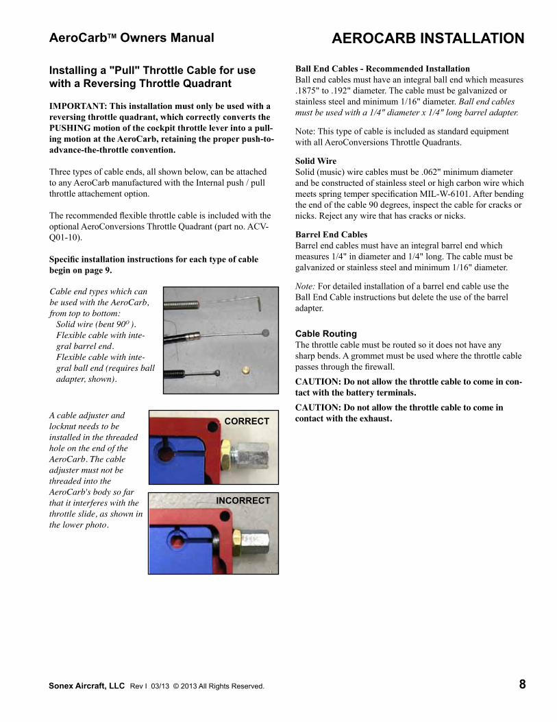
A cable adjuster and locknut needs to be installed in the threaded hole on the end of the AeroCarb. The cable adjuster must not be threaded into the AeroCarb's body so far that it interferes with the throttle slide, as shown in the lower photo.
AEROCARB INSTALLATION
CORRECT
INCORRECT
Cable end types which can be used with the AeroCarb, from top to bottom:
Solid wire (bent 90O ).Flexible cable with inte-gral barrel end.Flexible cable with inte-gral ball end (requires ball adapter, shown).
Installing a "Pull" Throttle Cable for use with a Reversing Throttle Quadrant
IMPORTANT: This installation must only be used with a reversing throttle quadrant, which correctly converts the PUSHING motion of the cockpit throttle lever into a pull-ing motion at the AeroCarb, retaining the proper push-to-advance-the-throttle convention.
Three types of cable ends, all shown below, can be attached to any AeroCarb manufactured with the Internal push / pull throttle attachement option.
The recommended flexible throttle cable is included with the optional AeroConversions Throttle Quadrant (part no. ACV-Q01-10).
Specific installation instructions for each type of cable begin on page 9.
Ball End Cables - Recommended Installation Ball end cables must have an integral ball end which measures .1875" to .192" diameter. The cable must be galvanized or stainless steel and minimum 1/16" diameter. Ball end cables must be used with a 1/4" diameter x 1/4" long barrel adapter.
Note: This type of cable is included as standard equipment with all AeroConversions Throttle Quadrants.
Solid Wire Solid (music) wire cables must be .062" minimum diameter and be constructed of stainless steel or high carbon wire which meets spring temper specification MIL-W-6101. After bending the end of the cable 90 degrees, inspect the cable for cracks or nicks. Reject any wire that has cracks or nicks.
Barrel End Cables Barrel end cables must have an integral barrel end which measures 1/4" in diameter and 1/4" long. The cable must be galvanized or stainless steel and minimum 1/16" diameter.
Note: For detailed installation of a barrel end cable use the Ball End Cable instructions but delete the use of the barrel adapter.
Cable RoutingThe throttle cable must be routed so it does not have any sharp bends. A grommet must be used where the throttle cable passes through the firewall.CAUTION: Do not allow the throttle cable to come in con-tact with the battery terminals.CAUTION: Do not allow the throttle cable to come in contact with the exhaust.
9
AeroCarbTM Owners Manual
Sonex Aircraft, LLC Rev I 03/13 © 2013 All Rights Reserved.
AEROCARB INSTALLATION
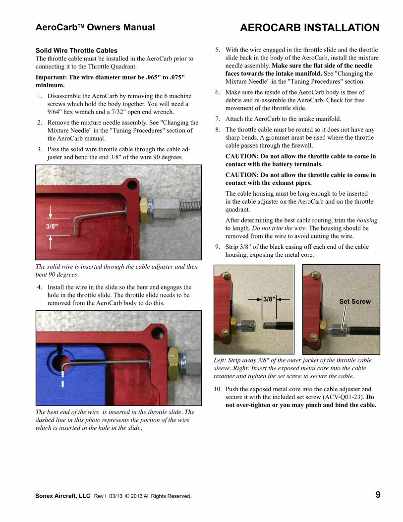
Solid Wire Throttle CablesThe throttle cable must be installed in the AeroCarb prior to connecting it to the Throttle Quadrant.Important: The wire diameter must be .065" to .075" minimum. 1. Disassemble the AeroCarb by removing the 6 machine
screws which hold the body together. You will need a 9/64" hex wrench and a 7/32" open end wrench.
2. Remove the mixture needle assembly. See "Changing the Mixture Needle" in the "Tuning Procedures" section of the AeroCarb manual.
3. Pass the solid wire throttle cable through the cable ad-juster and bend the end 3/8" of the wire 90 degrees.
The solid wire is inserted through the cable adjuster and then bent 90 degrees.
4. Install the wire in the slide so the bent end engages the hole in the throttle slide. The throttle slide needs to be removed from the AeroCarb body to do this.
5. With the wire engaged in the throttle slide and the throttle slide back in the body of the AeroCarb, install the mixture needle assembly. Make sure the flat side of the needle faces towards the intake manifold. See "Changing the Mixture Needle" in the "Tuning Procedures" section.
6. Make sure the inside of the AeroCarb body is free of debris and re-assemble the AeroCarb. Check for free movement of the throttle slide.
7. Attach the AeroCarb to the intake manifold. 8. The throttle cable must be routed so it does not have any
sharp bends. A grommet must be used where the throttle cable passes through the firewall.
CAUTION: Do not allow the throttle cable to come in contact with the battery terminals.
CAUTION: Do not allow the throttle cable to come in contact with the exhaust pipes.
The cable housing must be long enough to be inserted in the cable adjuster on the AeroCarb and on the throttle quadrant.
After determining the best cable routing, trim the housing to length. Do not trim the wire. The housing should be removed from the wire to avoid cutting the wire.
9. Strip 3/8" of the black casing off each end of the cable housing, exposing the metal core.
3/8"
Left: Strip away 3/8" of the outer jacket of the throttle cable sleeve. Right: Insert the exposed metal core into the cable retainer and tighten the set screw to secure the cable.
Set Screw
3/8"
The bent end of the wire is inserted in the throttle slide. The dashed line in this photo represents the portion of the wire which is inserted in the hole in the slide.
10. Push the exposed metal core into the cable adjuster and secure it with the included set screw (ACV-Q01-23). Do not over-tighten or you may pinch and bind the cable.

10
AeroCarbTM Owners Manual
Sonex Aircraft, LLC Rev I 03/13 © 2013 All Rights Reserved.
11. Insert the throttle cable wire between the washers and through the hole in the throttle cable clamp of the throttle quadrant but do not tighten it.
12. Push the exposed metal core of the throttle cable into the cable adjuster on the throttle quadrant and secure it with the included set screw (ACV-Q01-23). Do not over-tight-en or you may pinch and bind the cable.
13. Push the throttle lever to the "full throttle" position.14. Make sure the throttle slide of the AeroCarb is fully open
(full throttle position).15. Tighten the nut which secures the throttle cable wire in
the throttle cable clamp.16. Operate the cockpit throttle control through it's full range
of movement and make sure the throttle slide is opening completely as well as closing against the idle stop screw.
17. Trim the exposed throttle wire, leaving 1/4" to 3/8" ex-tending beyond the washers.
AEROCARB INSTALLATION
11
AeroCarbTM Owners Manual
Sonex Aircraft, LLC Rev I 03/13 © 2013 All Rights Reserved.
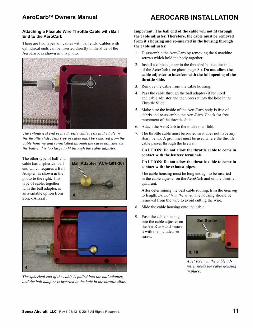
Attaching a Flexible Wire Throttle Cable with Ball End to the AeroCarbThere are two types of cables with ball ends. Cables with cylindrical ends can be inserted directly in the slide of the AeroCarb, as shown in this photo.
Important: The ball end of the cable will not fit through the cable adjuster. Therefore, the cable must be removed from it's housing and re-inserted in the housing through the cable adjuster. 1. Disassemble the AeroCarb by removing the 6 machine
screws which hold the body together. 2. Install a cable adjuster in the threaded hole at the end
of the AeroCarb (see photo, page 8.). Do not allow the cable adjuster to interfere with the full opening of the throttle slide.
3. Remove the cable from the cable housing. 4. Pass the cable through the ball adapter (if required)
and cable adjuster and then press it into the hole in the Throttle Slide.
5. Make sure the inside of the AeroCarb body is free of debris and re-assemble the AeroCarb. Check for free movement of the throttle slide.
6. Attach the AeroCarb to the intake manifold. 7. The throttle cable must be routed so it does not have any
sharp bends. A grommet must be used where the throttle cable passes through the firewall.
CAUTION: Do not allow the throttle cable to come in contact with the battery terminals.
CAUTION: Do not allow the throttle cable to come in contact with the exhaust pipes.
The cable housing must be long enough to be inserted in the cable adjuster on the AeroCarb and on the throttle quadrant.
After determining the best cable routing, trim the housing to length. Do not trim the wire. The housing should be removed from the wire to avoid cutting the wire.
8. Slide the cable housing onto the cable.
The cylindrical end of the throttle cable rests in the hole in the throttle slide. This type of cable must be removed from the cable housing and re-installed through the cable adjuster, as the ball-end is too large to fit through the cable adjuster.
The other type of ball-end cable has a spherical ball end which requires a Ball Adapter, as shown in the photo to the right. This type of cable, together with the ball adapter, is an available option from Sonex Aircraft.
AEROCARB INSTALLATION
Ball Adapter (ACV-Q01-36)
The spherical end of the cable is pulled into the ball adapter, and the ball adapter is inserted in the hole in the throttle slide.
4
4A set screw in the cable ad-juster holds the cable housing in place.
Set Screw
9, 10
9. Push the cable housing into the cable adjuster on the AeroCarb and secure it with the included set screw.

12
AeroCarbTM Owners Manual
Sonex Aircraft, LLC Rev I 03/13 © 2013 All Rights Reserved.
AEROCARB INSTALLATION
11, 14, 18
10. Insert the throttle cable wire between the washers and through the hole in the throttle cable clamp but do not tighten it.
11. Push the cable housing into the cable adjuster on the throttle quadrant and secure it with the included set screw.
12. Push the throttle lever to the "full throttle" position.13. Make sure the slide of the AeroCarb is fully open (full
throttle position).14. Tighten the nut which secures the throttle cable wire in
the throttle cable clamp.15. Trim the throttle wire.

13
AeroCarbTM Owners Manual
Sonex Aircraft, LLC Rev I 03/13 © 2013 All Rights Reserved.
Attaching a Flexible Throttle Cable with a Wire Stop 1. Disassemble the AeroCarb by removing the 6 machine
screws which hold the body together. 2. Install a cable adjuster in the threaded hole on the end
of the AeroCarb. Do not allow the cable adjuster to interfere with the full opening of the throttle slide. See photos on page 8.
4. Pass the flexible throttle cable through the cable adjuster and insert it through the wire stop. The slide has been drilled to allow the cable to extend through, and approxi-mately 1/4" beyond, the wire stop.
3. Insert a wire stop (p/n ACV-T01-19) into the recess in the throttle slide.
Wire stop.
The flexible throttle cable inserted through the cable adjuster and wire stop. Note: The throttle slide is drilled to allow the cable to pass through the wire stop approximately 1/4".
8. The throttle cable must be routed so it does not have any sharp bends. A grommet must be used where the throttle cable passes through the firewall.
CAUTION: Do not allow the throttle cable to come in contact with the battery terminals.
CAUTION: Do not allow the throttle cable to come in contact with the exhaust pipes.
The cable housing must be long enough to be inserted in the cable adjuster on the AeroCarb and on the throttle quadrant.
After determining the best cable routing, trim the housing to length. Do not trim the cable. The housing should be removed from the cable to avoid cutting the cable.
5. Install a 1/8" long 8-32 socket set screw (part number ACV-Q01-23) in the cable stop to lock the cable in place. The set screw must be below the surface of the wire stop or it will interfere with the smooth operation of the throttle slide.
Install a socket set screw to lock the cable in place.
A set screw in the cable ad-juster holds the cable housing in place.
Set Screw
10, 14, 18
3, 4
9. Push the cable hous-ing into the cable ad-juster on the AeroCarb and secure it with the included set screw (ACV-Q01-23). Do not over-tighten or you will pinch and bind the cable.
10. Insert the throttle cable between the washers and through the hole in the throttle cable clamp but do not tighten it.
9, 11
11. Push the cable housing into the cable adjuster on the throttle quadrant and secure it with the included set screw. Do not over-tighten or you will pinch and bind the cable.
12. Push the throttle lever to the "full throttle" position.13. Make sure the slide of the AeroCarb is fully open (full
throttle position).14. Tighten the nut which secures the throttle cable wire in
the throttle cable clamp.15. Trim the throttle cable.
AEROCARB INSTALLATION
6. Make sure the inside of the AeroCarb body is free of debris and re-assemble the AeroCarb. Check for free movement of the throttle slide.
7. Attach the AeroCarb to the intake manifold.

14
AeroCarbTM Owners Manual
Sonex Aircraft, LLC Rev I 03/13 © 2013 All Rights Reserved.
AEROCARB INSTALLATION
Install the Mixture CableThe mixture cable must be a push-pull boden wire style cable.Cable RoutingThe mixture cable must be routed so it does not have any sharp bends. A grommet must be used where the mixture cable passes through the firewall.CAUTION: Do not allow the mixture cable to come in contact with the battery terminals.CAUTION: Do not allow the mixture cable to come in contact with the exhaust pipes.
Connecting the Mixture CableThere are two types of mixture cable clamps. The most com-mon is a hole through the intake bell with a set screw to lock the cable in place. Some models, however, have a clamp as-sembly attached to the body of the AeroCarb.Note: Set-up of the mixture control is identical for either cable clamping method.
1. If necessary, up-drill the hole in the mixture cable clamp to fit your cable. Do not over-size the hole.
2. Insert the mixture cable housing in the mounting hole. Do not tighten the clamping screw at this time.
The left photo shows the most common mount for the mixture cable - a passage through the intake bell with a set screw (ar-row) to lock the cable in place.The right photo shows the clamp fitted to some models of the AeroCarb. The cable passes through the clamp and is secured by tightening the two screws.
3. Pass the mixture cable through the swivel nut in the mix-ture arm. Do not tighten the swivel nut at this time.
45O
Pass the mixture cable through the swivel nut as shown.
4. Push the cockpit mixture control knob all the way in (full rich).
5. Rotate the mixture arm 45O from perpendicular to the carburetor body, as shown in the following photo.
6. Slide the mixture cable housing in the mounting hole as needed until there is 2" of wire exposed between the mixture arm and the end of the mixture cable housing (see photo). Make sure the mixture arm is still in position (per step 5) and the cockpit mixture control knob is still pushed all the way in ("Full Rich").
7. Secure the mixture cable in the mixture cable clamp. Do not over-tighten the set screw used on most models of the AeroCarb. The set screw should firmly grip the mixture cable housing, but not bind the movement of the wire. The clamp-style mount can be fully tightened with-out crushing the cable.
8. Apply Locktite 242 to the screw of the swivel nut and tighten it against the wire. Do not over-tighten the screw. The set screw should firmly grip the mixture cable but still allow the swivel freedom to turn as the mixture arm is operated.
Setting up the mixture cable as shown in this photo will pro-vide full-range mixture control.
2"

15
AeroCarbTM Owners Manual
Sonex Aircraft, LLC Rev I 03/13 © 2013 All Rights Reserved.
9. Operate the mixture knob several times. The mixture should operate smoothly. If it does not, make sure the mixture cable set screw has not been over-tightened (step 7), the swivel nut has not been over-tightened, and the cable routing is free of sharp bends.
10. Pull the mixture cable out until it stops ("Idle Cut-Off"). The mixture control arm must be in the "closed" position with some wire still exposed beyond the cable housing. If there is no wire visible (bottom photo), the mixture arm may not be fully closed.
11. Push the cockpit mixture control knob all the way in ("Full Rich"). The mixture arm must be at least 45O from perpendicular to the carburetor body, as shown in step 5.
Note: The position of the mixture arm on the fuel valve can be adjusted if needed.
a. Loosen the swivel nut and remove the mixture cable.b. Turn the mixture arm clockwise until the fuel valve is
seated in the off position.c. Loosen the screw which locks the mixture arm on the
fuel valve.
When the cockpit mixture control knob is pulled all the way out (Idle Cut-off), there must still be some wire exposed between the cable housing and the mixture lever (see arrow). If there isn't, contact with the cable housing may keep the mixture arm from closing fully.
d. Rotate the mixture arm on the fuel shaft to the desired position. This will be the new "Idle Cut-off" position of the mixture arm.
e. Tighten the screw to lock the mixture arm in place.f. Reconnect the mixture cable.g. Make sure the cockpit mixture control still provides
enough movement of the mixture arm to open the valve from "Idle Cut-off" to "Full Rich".
A screw locks the mixture arm in place on the fuel valve. Loosening the screw allows the position of the mixture arm to be adjusted.
Fuel Valve
Lock Screw
AEROCARB INSTALLATION

16
AeroCarbTM Owners Manual
Sonex Aircraft, LLC Rev I 03/13 © 2013 All Rights Reserved.
Install the Fuel LineUse "AN" aircraft grade fuel lines and fittings to connect the AeroCarb to your fuel system.The fuel line must flow smoothly from the gascolator to the carburetor, with no part of the fuel hose rising higher than the carburetor fuel inlet. If the hose is higher than the fuel inlet at any point between the gascolator and the carburetor, an air pocket can form and hinder fuel flow.The body of the AeroCarb is tapped to accept 1/8 NPT fittings. Apply teflon paste (do not use teflon tape) to the threads before installation.
This view shows very clearly a smooth fuel line routing, with the inlet of the AeroCarb the highest point between the AeroCarb and the gascolator.
The fuel line connection at the carburetor.
AEROCARB INSTALLATION
Intake Air, Air Filter, and Carburetor Heat InstallationThe intake bell of the AeroCarb is designed to accept 2-1/4" SCAT tubing. It may also be fitted directly with the optional AeroConversions air filter assembly (see page 17).
Carburetor Heat The design of the AeroCarb makes it resistant to carburetor icing typically associated with carburetors that have venturis and butterfly valves. While each owner must make their own decision on installing and using carburetor heat - and some countries require it - we do not recommend it's use.
Intake Air and Air FilteringThe AeroCarb must be allowed to draw in combustion air freely - it is not designed for use with ram air. Ram air will cause the mixture to become lean as speed increases.Intake air can be drawn through a remotely mounted carb heat/air filter box, or the optional AeroConversions air filter. Instal-lation of the optional AeroConversions air filter is described on the next page.

17
AeroCarbTM Owners Manual
Sonex Aircraft, LLC Rev I 03/13 © 2013 All Rights Reserved.
Installing the Optional AeroConversions Air Filter or Intake Flange AdapterThe optional AeroConversions air filter or intake flange adapt-er are mounted directly to the intake bell of the AeroCarb. While these instructions are illustrated with photos of the air cleaner, they apply equally to the intake flange adapter.IMPORTANT: While drilling and tapping the intake bell use care to keep debris from entering the AeroCarb. 1. Slide the air filter or intake flange adapter onto the intake
bell as far as it will go.Note: The mounting flange has 4 mounting holes, however only one bolt is needed to secure the air filter to the AeroCarb. At least two bolts must be used to mount the intake flange adapter. The other holes may be used for additional mounting bolts, if desired.
2. Insert a 3/16" diameter drill bit through any of the mount-ing holes in the air filter or intake flange adapter and twist it a few times to leave a mark on the AeroCarb's intake bell.
3. Remove the air filter and carefully drill a 1/8" diameter pilot hole squarely through the intake bell at the mark.
Twist, by hand, a 3/16" drill bit in one of the mounting holes to mark the bell of the AeroCarb.
4. Up-drill the hole with a #21 drill. 5. Tap the hole with a 10-32 tap.
The intake bell drilled and tapped for the AN3 bolts
The air filter is attached with the AN3 bolt and AN960-10 washer.
AEROCARB INSTALLATION
6. Slide the air filter in place, apply Locktite 242 to the threads of the AN3 bolt, and install the bolt and AN960-10 washer.

18
AeroCarbTM Owners Manual
Sonex Aircraft, LLC Rev I 03/13 © 2013 All Rights Reserved.
TUNING PROCEDURES
How the AeroCarb WorksThe Fuel Mixture Needle and Throttle Slide move as one unit when the cockpit throttle control is operated. The position of the mixture needle relative to the throttle slide determines the fuel/air ratio. The tuning process establishes the optimum fuel/air ratio for the full range of throttle travel.Fuel MeteringFuel enters the AeroCarb at the Mixture Control Valve, which is cockpit controllable with a mixture control cable. The valve controls the volume of fuel available to the engine: from none (cockpit mixture control set to "Full Lean" or "Idle Cut-off"), to maximum (cockpit mixture control set to "Full Rich"). Like any other carburetor with a cockpit mixture control, the mixture is normally set to "Full Rich" for start-up, climb, and landing, yet provides mixture control (leaning) for optimum performance and fuel efficiency while cruising. Important: When tuning the AeroCarb, the Mixture Control Valve must be in the "Full Rich" position.
For Best Results...Read and understand this entire chapter before tuning your AeroCarb. This chapter is broken into three sections: How the AeroCarb Works, Idle and Mixture Adjustments, and Tuning the AeroCarb. The first two sections contain important infor-mation you should understand before you begin to tune your AeroCarb.
The fuel inlet and Mixture Control Valve.
The fuel passing through the AeroCarb for combustion is me-tered by a tapered Fuel Mixture Needle. The needle moves in-side the fuel orifice as the cockpit throttle control is operated, altering the amount of fuel that can pass through the orifice.
Mixture Control Valve
Fuel Inlet
Shown here in the "Off" position
The AeroCarb is supplied with 3 different fuel needles. Each needle provides a different over-all fuel/air ratio and is stamped with a number: 1 through 3. The #1 needle is the leanest, and the #3 needle is the richest. The #2 needle is pre-installed, and is the correct needle for the majority of installa-tions.Air MeteringCombustion air is metered by the Throttle Slide. The throttle slide moves when the cockpit throttle control is operated, altering the opening of the air passage.
This cut-away view shows the tapered fuel needle and fuel orifice. The throttle slide, in which the fuel needle is mounted, is also identified.
Tapered Fuel Needle
Fuel Orifice
Throttle Slide
This cut-away view shows that at "Full Throttle", the throttle slide exposes the entire intake air passage.
Section ContentsFor Best Results... .............................................................. 18How the AeroCarb Works ...................................................... 18Mixture and Idle Adjustments ................................................ 19Changing the Mixture Needle ................................................ 20Adjusting the Idle Speed Stop Screw ..................................... 21Adjusting the "Full Throttle" Position of the Throttle Slide .. 22When is it in Tune? ................................................................ 23Compensating for Seasonal Changes ..................................... 23Tuning the AeroCarb - Step by Step ...................................... 24

19
AeroCarbTM Owners Manual
Sonex Aircraft, LLC Rev I 03/13 © 2013 All Rights Reserved.
Mixture and Idle AdjustmentsIMPORTANT: Read and become familiar with the entire Tuning Procedure before tuning your AeroCarb. This section does not describe how to tune the AeroCarb, rather, how to make the individual mixture and idle adjustments which will be necessary during the tuning process.Adjusting the Mixture NeedleThe Mixture Needle is mounted in a Needle Carrier which is installed in the throttle slide. The needle carrier has an Adjust-ment Screw which allows infinite adjustment of the mixture needle.
TUNING PROCEDURES
Dust Cap
Remove the dust cap to gain access to the Needle Adjustment Screw.
Needle Carrier and Adjustment Screw.
Mixture Needles
While it is seldom necessary to remove the needle carrier dur-ing tuning, this photo shows clearly the needle carrier which is installed in the throttle slide. The AeroCarb comes with three different needles.
To adjust the Mixture Needle: 1. Lock the throttle in the "Full Throttle" position. 2. Remove the dust cap
Idle SpeedThe idle speed is set by the position of the Idle Speed Stop Screw (if equipped) or the Idle Speed Stop Nut (early produc-tion AeroCarbs). These limit how far the throttle slide can close, assuring the engine has an adequate supply of fuel and air to run when the cockpit throttle control is fully retarded.
For most installations the throttle slide should be allowed to open all the way. However, some installations may encounter rough engine operation or "balking" near full throttle. If this occurs, note the position of the throttle slide and adjust the throttle linkage to prevent the slide from opening fully. On some installations this may be as much as 1/4". See page 22.
The Idle Speed Stop Screw on late-production AeroCarbs limits how far the throttle can close. The Idle Screw is locked in position by a locknut which is tightened against the body of the AeroCarb after the idle speed has been set.
Idle Speed Stop Screw
Idle Stop Nut
The Idle Speed Stop Nut on early-production AeroCarbs limits how far the throttle can close. The nut's position is adjusted on the threaded rod so it will contact the Aerocarb's body and limit how far the thrttle can close, thus setting the idle speed.

20
AeroCarbTM Owners Manual
Sonex Aircraft, LLC Rev I 03/13 © 2013 All Rights Reserved.
Set Screw
Use a 3/16" ball end hex wrench to remove the set screw which locks the Needle Carrier in place.
3. A set screw locks the Needle Carrier in place. Remove the set screw with a 3/16" ball end hex wrench.
4. Adjust the mixture needle with a 3/16" ball end hex wrench. Adjust the needle in 1/8 to 1/2 (maximum) turn increments.To richen the mixture, turn the wrench counter-clockwise.To lean the mixture, turn the wrench clockwise.
Use a 3/16" hex wrench to adjust the position of the Mixture Needle.
5. Re-install the set screw so it is snug against the needle carrier.
IMPORTANT: Always re-install the set screw after an adjustment has been made. Running the engine without the set screw in place can allow the position of the mix-ture needle to change.
6. Re-install the dust cap.
TUNING PROCEDURES
Changing the Mixture NeedleThe AeroCarb is supplied with three different mixture needles, each offering a richer or leaner fuel ratio across the entire throttle range. Each needle is stamped with a number on its flat taper: 1, 2 or 3. Needle 1 provides the leanest mixture, and 3 the richest. The number 2 needle is factory installed and is the correct needle for most applications.Note: Other needle profiles are available. Please contact AeroConversions to discuss your needs if the standard needles do not provide proper results.A needle should only be replaced after tuning efforts have shown the installed needle is too rich or too lean across the entire throttle range, as described in "Tuning the AeroCarb".To Replace a Mixture Needle: 1. Lock the throttle in the "Full Throttle" position. 2. Remove the dust cap. 3. Remove the set screw with a 3/16" ball end hex wrench. 4. Remove the needle carrier from the throttle slide with a
3/16" ball end hex wrench turned counter-clockwise.
5. Loosen the set screw which locks the mixture needle in the needle carrier with a 1/16" hex wrench and remove the needle.
6. Install a needle with a richer or leaner profile, as needed. Make sure the notch in the needle lines up with the set screw and re-install the set screw.
Needle Number
Notch
Set Screw
Use a 3/16" hex wrench to remove the set screw which locks the Needle Carrier in place.

21
AeroCarbTM Owners Manual
Sonex Aircraft, LLC Rev I 03/13 © 2013 All Rights Reserved.
7. Use a fine point marker to mark the beginning of the needle's taper. Make sure the mark encircles the entire needle.
8. Re-install the needle carrier in the throttle slide. Make sure the flat, tapered side of the needle faces the engine side of the AeroCarb. Screw the carrier into the throttle slide until the marker line on the needle is visible at the edge of the throttle slide.
Draw a line around needle where the taper begins.
Marker line where taper begins
Screw the carrier into the Throttle Slide until the beginning of the taper is even with the edge of the slide, as shown in this cut-away.
Marker line where taper begins
Adjusting the Idle Speed Stop Screw or NutThe idle speed stop screw or nut control the idle speed by lim-iting how far the throttle slide can close. If the slide closes too far, fuel and air will be restricted and the engine will stop. If the slide does not close enough, the engine will idle too high.
The idle speed stop screw is adjusted with a 9/64" hex wrench. The screw is locked in place with lock nut tightened against the AeroCarb's body.
To increase the idle speed, turn the idle screw or nut clockwise.To decrease the idle speed, turn the idle screw or nut counter-clockwise.
Idle adjustments may be needed during initial tuning, but the final idle setting is performed after the mixture needle has been properly set and the engine is warm (oil temp. at least 100O F.) Refer to your engine specifications for the correct idle speed.
A 9/64" hex wrench is used to adjust the Idle Speed Stop Screw. The lock nut is tightened / loosened with an 11/32" open-end wrench.
TUNING PROCEDURES
9. Re-install the set screw so it is snug against the needle carrier.
IMPORTANT: Always re-install the set screw after an adjustment has been made. Running the engine without the set screw in place can allow the position of the mix-ture needle to change.
10. Re-install the cap.
Idle Speed Stop Screw
Idle Stop Nut
The Idle Speed Stop Nut on early-production AeroCarbs is an elastic stop nut which will hold its position. It can be adjusted with 7/16 wrench.

22
AeroCarbTM Owners Manual
Sonex Aircraft, LLC Rev I 03/13 © 2013 All Rights Reserved.
TUNING PROCEDURES
Adjusting the "Full Throttle" Position of the Throttle SlideSome installations may encounter rough engine operation or "balking" near full throttle. If this occurs, the movement of the throttle slide needs to be limited to prevent it from opening and exposing the entire intake air passage. On some installa-tions this may be as much as 1/4".To adjust the "Full Throttle" position for "Push/Pull" throttle cable installations: 1. Note the position of the throttle slide just before rough
operation begins. 2. Push the cockpit throttle control fully forward and lock it
in place.
Loosen the throttle cable clamp and slide the throttle cable in the proper direction to keep it from opening completely.
3. Loosen the throttle cable clamp with a 9/64 hex wrench. 4. Slide the throttle cable back until the throttle slide is in the
position noted in step 1. 5. Tighten the throttle cable clamp.
Throttle Cable ClampThrottle Cable
To adjust the "Full Throttle" position for "Pull" style Reversing Throttle Quadrant installations: 1. Note the position of the throttle slide just before rough
operation begins. 2. Adjust the throttle cable's length/position so the throttle
lever is in the full throttle position, but the throttle slide is in the position noted in step 1. This will generally require shortening the throttle cable.
Note: In some installations the cable adjuster (see page 8) can be threaded further into the AeroCarb's body and used as a positive stop for limiting the throttle slide's travel.

23
AeroCarbTM Owners Manual
Sonex Aircraft, LLC Rev I 03/13 © 2013 All Rights Reserved.
Compensating for Seasonal ChangesSome climates may require small seasonal adjustments to the mixture needle. These are generally needed once in late Fall and again in late Spring to compensate for changing air density. If your engine exhibits symptoms of running too rich as the weather warms, and too lean as the weather cools, the mixture needle may need to be adjusted no more than 1/4 to 1/2 turn richer or leaner, as appropriate.
When is it in Tune?A properly tuned AeroCarb will accept throttle changes smoothly, without missing or balking, and, at full throttle, will exhibit an Exhaust Gas Temperature (EGT) increase of 90O to 100OF when the cockpit mixture control is pulled from "Full Rich" to "Peak Lean".We define Peak Lean as the engine manufacturer's maximum recommended EGT. While this varies from engine to engine, most engines set a maximum EGT near 1400OF. Refer to your engine's operating limits.Note: Since calibration of EGT gauges/probes is difficult, the EGT should be used to measure change in temperature rather than absolute temperature.Peak Lean generally occurs just before the engine begins to run rough. Continuing to pull the cockpit mixture control fur-ther lean will result in higher than recommended EGTs, rough engine operation, and, eventually, fuel starvation.What is "Rich"?We define "rich" as a fuel/air ratio which has too much fuel.Symptoms:l Black, smoky exhaust.l Engine runs with weak, intermittent firing.l Pulling the mixture control knob towards lean will
improve engine firing and reduce the amount of black exhaust.
l EGT increases more than 100OF when the cockpit mix-ture control is pulled back from "Full Rich" to "Peak Lean".
Action to take:l Turn the needle adjustment clockwise in 1/8 to 1/4 turn
increments and run the engine to test the new setting.l If continued needle adjustments do not produce the de-
sired 90O to 100OF EGT spread, install a lowered number needle. See page 20.
l If your fuel system requires a fuel pump, the pressure regulator may need to be set lower (1 to 2 psi is normal).
What is "Lean"?We define "lean" as a fuel/air ratio which has too little fuel.Symptoms:l Engine will not startl Engine runs rough and exhaust is free of black smoke.l Engine runs rough and does not improve, or stalls, as the
cockpit mixture control is pulled towards lean.l Engine will not take throttle.
l EGT climbs quickly to, and above, temperatures recom-mended for your engine.
l EGT increases less than 90OF when the cockpit mixture control is pulled back from "Full Rich" to peak lean.
Action to take:l Turn the needle adjustment counter- clockwise in 1/8 to
1/4 turn increments and run the engine to test the new setting.
l If continued needle adjustments do not produce the de-sired 90O to 100OF EGT spread, install a higher number needle. See page 20.
l If your fuel system requires a fuel pump, the pressure regulator may need to be set higher (1 to 2 psi is normal).
TUNING PROCEDURES

24
AeroCarbTM Owners Manual
Sonex Aircraft, LLC Rev I 03/13 © 2013 All Rights Reserved.
Tuning the AeroCarb - Step by StepIMPORTANT: Read and understand this entire chapter before tuning your AeroCarb. This chapter is broken into three sections: How the AeroCarb Works, Mixture and Idle Adjust-ments, and Tuning the AeroCarb. The first two sections contain important information you should understand before you begin to tune your AeroCarb.DANGER: Avoid serious injury or death. Turn the engine off using a checklist before making any adjustments to the AeroCarb. A typical checklist is provided on page 25 of this manual, but it may need to be modified for your particular aircraft.DANGER: Avoid serious injury or death. Remain clear of the propeller at all times while tuning the AeroCarb.DANGER: Avoid serious injury or death. Tie down and chock the aircraft while tuning the carburetor.WARNING: Avoid serious burns. The engine and exhaust will become hot during the tuning process.CAUTION: Avoid damaging the engine. Air cooled engines are not adequately cooled during ground operations. Monitor your engine's temperatures and oil pressure, and limit ground running as much as possible.IMPORTANT: Tuning should be done with a qualified helper. One person remains in the cockpit to operate the throttle and monitor the engine instruments while the other makes adjust-ments to the AeroCarb (only after the engine is shut down!) and observes the exhaust.
Tools Required q 3/16" Hex Wrench q9/64" Hex WrenchqStart-up checklist (see page 25.)qShut-down Checklist (see page 25.)
To Tune the AeroCarb: 1. Tie-down and chock the aircraft. 2. Set the parking brake 3. Make sure the aircraft has an adequate fuel supply. 4. Start the engine using an appropriate checklist.l If the engine starts and idles smoothly, even with slightly
black exhaust, allow the engine's oil temperature to warm up to 100OF. Do not allow the CHT and EGT to exceed the engine manufacturer's limit. Continue to step 5.
l If the engine does not start, or starts and runs rough, shut down the engine using an appropriate checklist and adjust the mixture needle as needed. See "When is it in Tune?" page 23. After making an adjustment, repeat this step.
5. Gradually increase the throttle to full static RPM.l If the engine takes full throttle well with clean exhaust,
continue with step 6.l If the engine takes full throttle well but exhibits some
black exhaust, shut down the engine using an appropri-ate checklist and adjust the mixture needle leaner. See "When is it in Tune?" page 23. After making an adjust-ment, repeat step 4.
l If the engine runs rough, balks, or quits, shut down the engine using an appropriate checklist and adjust the mix-ture needle as needed. See "When is it in Tune?" page 23. After making an adjustment, repeat step 4.
l If the engine takes throttle well but balks or runs rough only at or near full throttle, the Throttle Slide's travel needs to be limited. Shut down the engine using an ap-propriate checklist and adjust the Throttle Slide. See page 22. After making an adjustment, repeat step 4.
6. With the engine running at full throttle: a. Gradually pull the cockpit mixture control lean until
the engine begins to run rough, and then richen slightly for smooth operation. Note the EGT.
b. Advance the cockpit mixture control to full rich and note the EGT.
c. Retard the throttle smoothly to idle and shut down the engine using an appropriate checklist
l If the EGT spread was 90O to 100OF, and the engine re-sponded well to the throttle through the entire range, the mixture needle is properly set. Continue with step 7.
l If the EGT spread was greater than 90O to 100OF, the mixture is too rich. Adjust the mixture needle for a leaner mixture (see page 19).
l If the EGT spread was less than 90O to 100OF, the mixture is too lean. Adjust the mixture needle for a richer mixture (see page 19).
l If continued adjustment does not achieve the desired 90O to 100OF spread, try the next numbered mixture needle. See "Changing the Mixture Needle", page 20.
7. After the mixture needle is properly set, final idle adjust-ments can be made (see page 21).
8. Test run the engine through it's full RPM range and make sure it:
l Responds to the throttle smoothlyl Idles properlyl Exhibits a 90O to 100OF EGT differential at full throttle
when the cockpit mixture control is pulled from full rich to "peak lean".
Note: Additional tuning may be needed after initial flight test-ing or after a new engine has been broken in.
TUNING PROCEDURES
25
AeroCarbTM Owners Manual
Sonex Aircraft, LLC Rev I 03/13 © 2013 All Rights Reserved.
OPERATING CHECKLISTS
Leaning for Best Performance at CruiseTake-off, climb, and landing must always be performed with the mixture set at full rich. Once level cruise has been estab-lished, however, engine performance and fuel economy will both benefit by proper leaning. 1. Establish level cruise. 2. Slowly pull the mixture control Lean until the engine
begins to run a little rough. 3. Note the maximum indicated EGT (if the aircraft is
equipped with an EGT). 4. Slowly push the mixture control Rich until the engine
runs smooth. If your aircraft has an EGT, this will be approximately 50 degrees F. cooler than the temperature noted in step 3.
Adjusting the mixture as described above will result in maxi-mum power (higher RPMs), as well as minimum fuel con-sumption for any throttle setting.Important: Mixture adjustment must be repeated with any change in throttle setting or altitude. 5. Push the mixture control to "Full Rich" before landing.
Starting Checklist - Hand ProppingDANGER: Do not attempt to hand prop an aircraft with-out proper training. Serious injury or death can occur.WARNING: Do not hand prop an aircraft equipped with an electric starter. Remove the aircraft from service until proper repairs can be made to the electric starting system. 1. Tie down and chock the aircraft. 2. Brakes - Set 3. Mags - Off 4. Mixture - Full Lean (Idle Cut-off) 5. Fuel Valve - On 6. Throttle - Slightly Open 7. Mixture - Full Rich for a few seconds then Full Lean.
This "primes" the engine. 8. Pull prop through 2 to 4 blades 9. Mags - On10. Prop engine until it starts.11. Mixture - Full RichIf the engine does not start, repeat procedure.
Starting Checklist - Electric Start 1. Brakes - Set 2. Mixture - Full Lean (Idle Cut-off) 3. Fuel Valve - On 4. Master - On 5. Mags - On 6. Throttle - Slightly Open 7. Fuel Pump - On 8. Clear Prop 9. Mixture - Full Rich Note: With the mixture open and the fuel valve on, fuel
will flow through the carburetor. Do not delay starting the engine.
10. Starter - EngagedThe engine will normally start with one or two turns of the propeller in warm weather and six to eight turns in cold weather. If the engine does not start immediately, pull the mix-ture off, turn off the fuel pump, and close the fuel valve before investigating the problem.
Flooded Engine - ClearingWeak, intermittent firing indicates flooding. Excess fuel can be cleared from the combustion chambers with the following procedure: 1. Mixture - Full Lean (Idle Cut-off) 2. Fuel pump - Off 3. Fuel shut off valve - Off 4. Mag switch - Off 5. Throttle - Full Open 6. Engage the starter for a few seconds. 7. Repeat the starting procedure.
Shut-Down Checklist 1. Mixture - Full Rich 2. Throttle - Idle 3. Fuel Pump - Off 4. Mixture - Full Lean (Idle Cut-off) 5. Ignition - Off 6. Fuel Valve - Off (Closed)
WARNING: Fire hazard. Failure to turn off the main fuel valve may result in fuel flowing from the AeroCarb after shut-down.
7. Master switch - Off 8. Mags - Off
Note: These basic checklists may need to be altered for your particular aircraft.
26
AeroCarbTM Owners Manual
Sonex Aircraft, LLC Rev I 03/13 © 2013 All Rights Reserved.
TROUBLESHOOTING
Sticky ThrottleImproper throttle cable used. Replace cable.Kinked or sharply bent throttle cable. Reroute cable to eliminate kinks, sharp bends.Throttle arm misaligned, causing side loads on throttle slide. Loosen the locknut on throttle arm and rotate throttle arm slightly on threaded rod until throttle moves freely. Carefully re-tighten lock nut against throttle arm.AeroCarb modified by installer with additional linkages, return springs, brackets, etc. Restore AeroCarb to original configuration and install accord-ing to this manual.Throttle cable lining melted from excessive heat. Replace cable. Route cable clear of exhaust system.
Sticky Mixture CableKinked or sharply bent mixture cable. Reroute cable to eliminate kinks, sharp bends.Unsupported length of mixture cable too long near AeroCarb mixture lever. Install mixture cable as shown in this manual.AeroCarb modified by installer with additional linkages, brackets, etc. Restore AeroCarb to original configuration and install accord-ing to this manual.Mixture cable lining melted from excessive heat. Replace cable. Route cable clear of exhaust system.
Fuel Leaks from AeroCarbBecause of the AeroCarb's floatless design, fuel will drip/flow from the AeroCarb if the fuel is on. The flow will increase if the throttle is open, the cockpit mixture control is moved towards "Rich", or a fuel pump is on. This is normal and does not represent a defect.To keep fuel from flowing from the AeroCarb when the engine is turned off, always keep the fuel shut-off valve turned off, the cockpit mixture control pulled out to "Idle Cut-off", the fuel pump off, and the throttle at "Idle". Always use one of the start-up/shut-down checklists in this manual to prevent fuel from running from the AeroCarb.Fuel leak from Mixture Control Valve Remove mixture control valve, replace O-Ring and lubricate it with fuel-proof valve seal.
The AeroCarb is an extremely simple design which can be expected to function faultlessly if properly installed and tuned. If you experience problems with your AeroCarb, please review this list of troubleshooting tips for possible causes, and the contents of this manual for proper installation/tuning/opera-tion. Should you be unable to identify or resolve your problem, do not hesitate to contact AeroConversions for technical assistance.
Unable to Tune the AeroCarbFuel delivery inadequate. Inspect fuel system for restrictions.Make sure the cockpit mixture control is set on "Full Rich" and the AeroCarb mixture lever is properly positioned.Make sure the fuel tank has sufficient fuel for consistent head pressure while tuning.Fuel delivery excessive. Install a pressure regulator if a fuel pump is used.Fuel pressure set too high/low on aircraft requiring a fuel pump.Mixture needle improperly installed. "Flat" of the mixture needle not facing the proper direction. Refer to the "Tuning Procedures" section of this manual.Mixture needle lock screw not installed after each mixture needle adjustment, allowing the needle to move while the engine is running. Install the mixture needle lock screw after each mixture ad-justment. Incorrect needle installed. Install a different needle per tuning instructions in this manual.Needle has been modified from original profile. Discard needle and replace with a new one from AeroConversions.Needle adjustments too aggressive. Limit needle adjustments to 1/2 turn or less.AeroCarb modified by installer. Restore AeroCarb to original configuration.Air intake restricted. Inspect air intake for restrictions, sharp bends, dirty air filters, etc.Ram air installed. Remove ram air.Engine requires service. An engine in need of maintenance will be difficult or impos-sible to tune. Check valve settings, cylinder compression, tim-ing, magnetos, spark plugs and wires. Inspect intake manifold for leaks.

27
AeroCarbTM Owners Manual
Sonex Aircraft, LLC Rev I 03/13 © 2013 All Rights Reserved.
PARTS LIST
23
22
21
34
5
1 2
25
24
25
17
6
98
1110
1213
14
15
16
19 7
20
AeroCarb Parts ListNote: When an "x" appears in a part number, substitute the AeroCarb size (1 through 5) for the "x". The sizes are shown in the chart above, and are stamped on the AeroCarb body.Key Part No. Description 1.........ACV-COx-10 ............Carburetor Body (as shown) ACV-COx-01 ............Carburetor Body (Slide cavity on intake side) 2.........ACV-COx-09 ............Delrin Gasket 3.........ACV-COx-02 ............Cover Plate 4.........ACV-Z01-50 .............Viton O-Ring (#135) 5.........ACV-C0x-05 .............Intake Bell, 1.5" O.D. Spigot (shown) ACV-C0x-06 .............Intake Bell, 2" O.D. Spigot ACV-C0x-07 .............Intake Bell, 2.5" Square Flange ACV-C0x-08 .............Intake Bell, 3" Square Flange 6.........ACV-Z01-61 .............MS Hex Nut (MS21042-08) 7.........ACV-C0x-12 .............Slide (Anodized (blue)) ACV-C0x-03 .............Slide (Teflon Coated) 8.........ACV-Z01-56 .............1/4-20 Jam Lock Nut 9.........ACV-C10-02 .............Slide Arm10........ACV-Z01-57 .............1/4-20 Cup Point Set Screw - S/S11 ........ACV-C10-05 .............Needle Holder12........ACV-Z01-58 .............6-32 x 1/8 Set Screw - S/S
AeroCarb Model Numbers* Throat Diameter: Model No.*: 26mm ..................ACV-C01 29mm ..................ACV-C02 32mm ..................ACV-C03 35mm ..................ACV-C04 38mm ..................ACV-C05*Model no. is stamped on body.
13........ACV-C10-1x .............Needle For "x", insert needle no. 1 thru 5; 1 is the leanest, 5 is the richest. Needles 1, 2 and 3 are provided with carb.14........ACV-Z01-51 .............Viton O-Ring (#010)15........ACV-C10-06 .............Mixture / Fuel Shaft16........ACV-C10-01 .............Mixture Adjustment Arm17........ACV-Z01-62 .............Azusa Wire Swivel Nut and Screw18........ACV-Z01-60 .............Plug, Black Plastic19........ACV-Z01-52 .............8-32 x 1" SHCS - S/S20........ACV-Z01-53 .............8-32 x 1-1/2" SHCS - S/S21........ACV-Z01-54 .............8-32 x 1/4" Patched SHCS - S/S22........ACV-C05-04 .............Bell, Intake Housing23........ACV-C10-34 .............Throttle Cable Sleeve Bushing24........ACV-C10-33 .............Throttle Cable Clamp25........ACV-Z01-55 .............8-32 x 1/2" Patched SHCS - S/S26........ACV-C10-35 .............Mixture Cable Mount, Reversed Body Modification27........ACV-Z01-52 .............8-32 x 1" Socket Head Cap Screw - S/S28........ACV-Z01-66 .............8-32 Jam Nut - S/S
18
26 Mixture Cable Clamp, Re-versed Body Modification (not shown)
Intake Side of AeroCarb
Engine Side of AeroCarb
Note: Specifications subject to change without notice.
27
28