AEROBELLTM COPES TM** - Finishing Brands · SERVICE INSTRUCTION LN-9230-00 AEROBELLTM COPESTM**...
40
SERVICE INSTRUCTION LN-9230-00 LN-9230-00 LN-9230-00 LN-9230-00 LN-9230-00 AEROBELL AEROBELL AEROBELL AEROBELL AEROBELL TM TM TM TM TM COPES COPES COPES COPES COPES TM** TM** TM** TM** TM** MODEL: 75850 MODEL: 75850 MODEL: 75850 MODEL: 75850 MODEL: 75850 IMPOR IMPOR IMPOR IMPOR IMPORTANT ANT ANT ANT ANT: Before using this equipment, : Before using this equipment, : Before using this equipment, : Before using this equipment, : Before using this equipment, carefully read SAFETY PRECAUTIONS, start- carefully read SAFETY PRECAUTIONS, start- carefully read SAFETY PRECAUTIONS, start- carefully read SAFETY PRECAUTIONS, start- carefully read SAFETY PRECAUTIONS, start- ing on page 1, and all instructions in this ing on page 1, and all instructions in this ing on page 1, and all instructions in this ing on page 1, and all instructions in this ing on page 1, and all instructions in this manual. Keep this Service Bulletin for future manual. Keep this Service Bulletin for future manual. Keep this Service Bulletin for future manual. Keep this Service Bulletin for future manual. Keep this Service Bulletin for future reference. reference. reference. reference. reference.
Transcript of AEROBELLTM COPES TM** - Finishing Brands · SERVICE INSTRUCTION LN-9230-00 AEROBELLTM COPESTM**...

SERVICE INSTRUCTIONLN-9230-00LN-9230-00LN-9230-00LN-9230-00LN-9230-00
AEROBELLAEROBELLAEROBELLAEROBELLAEROBELLTMTMTMTMTM COPES COPES COPES COPES COPESTM**TM**TM**TM**TM**
MODEL: 75850MODEL: 75850MODEL: 75850MODEL: 75850MODEL: 75850
IMPORIMPORIMPORIMPORIMPORTTTTTANTANTANTANTANT: Before using this equipment,: Before using this equipment,: Before using this equipment,: Before using this equipment,: Before using this equipment,carefully read SAFETY PRECAUTIONS, start-carefully read SAFETY PRECAUTIONS, start-carefully read SAFETY PRECAUTIONS, start-carefully read SAFETY PRECAUTIONS, start-carefully read SAFETY PRECAUTIONS, start-ing on page 1, and all instructions in thising on page 1, and all instructions in thising on page 1, and all instructions in thising on page 1, and all instructions in thising on page 1, and all instructions in thismanual. Keep this Service Bulletin for futuremanual. Keep this Service Bulletin for futuremanual. Keep this Service Bulletin for futuremanual. Keep this Service Bulletin for futuremanual. Keep this Service Bulletin for futurereference.reference.reference.reference.reference.


LN-9230-00
SAFETY:SAFETY:SAFETY:SAFETY:SAFETY:
SAFETY PRECAUTIONS............................................................................................................HAZARDS / SAFEGUARDS........................................................................................................
PAGEPAGEPAGEPAGEPAGE
INTRODUCTION:INTRODUCTION:INTRODUCTION:INTRODUCTION:INTRODUCTION:
CONTENTSCONTENTSCONTENTSCONTENTSCONTENTS
GENERAL DESCRIPTION..........................................................................................................FEATURES...................................................................................................................................SPECIFICATIONS.......................................................................................................................MODELS / OPTION & REPLACEMENT ITEMS /MODEL IDENTIFICATION...........................................................................................................AIR FILTRATION REQUIREMENTS..........................................................................................
INSTALLATION:INSTALLATION:INSTALLATION:INSTALLATION:INSTALLATION:
AIR FILTER INSTALLATION.......................................................................................................AIR & FLUID CONNECTIONS....................................................................................................TUBE CONNECTIONS................................................................................................................BEARING AIR..............................................................................................................................SHAPING AIR..............................................................................................................................BRAKE AIR...................................................................................................................................TURBINE AIR...............................................................................................................................FLUID INLET................................................................................................................................HIGH VOLTAGE..........................................................................................................................GROUND......................................................................................................................................AEROBELL COPES SYSTEM INTERLOCKS...........................................................................
OPERATION:OPERATION:OPERATION:OPERATION:OPERATION:
TURBINE SPEED........................................................................................................................BEARING AIR..............................................................................................................................BRAKE AIR...................................................................................................................................ELECTROSTATIC VOLTAGE.....................................................................................................SHAPING AIR..............................................................................................................................TARGET DISTANCE...................................................................................................................TURBINE AIR...............................................................................................................................COATING MATERIAL CONDUCTIVITY.....................................................................................ELECTRODE REMOVAL PROCEDURE FOR OPTIONALDIRECT CHARGING METHOD..................................................................................................
1-51-51-51-51-5
6-96-96-96-96-9
10-1310-1310-1310-1310-13
14-1714-1714-1714-1714-17
12
666
78
1010111112121212121212
1414141515151516
16
Aerobell Copes - Contents

LN-9230-00
Aerobell Copes - Contents
MAINTENANCE:MAINTENANCE:MAINTENANCE:MAINTENANCE:MAINTENANCE:
CLEANING PROCEDURES......................................................................................................VIBRATION NOISE....................................................................................................................PREVENTIVE MAINTENANCE.................................................................................................MEAN TIME BETWEEN FAILURE............................................................................................DISASSEMBLY / REASSEMBLY PROCEDURES...................................................................TURBINE MAINTENANCE / REPAIR ITEMS...........................................................................
PARTS IDENTIFICATION:PARTS IDENTIFICATION:PARTS IDENTIFICATION:PARTS IDENTIFICATION:PARTS IDENTIFICATION:
PART VARIATIONS....................................................................................................................QUICK CHANGE MANIFOLD ASSY / PARTS LIST.................................................................QUICK CHANGE MOTOR ASSEMBLY / PARTS LIST............................................................MODEL IDENTIFICATION TABLES..........................................................................................TURBINE MOTOR ASSEMBLY / PARTS LIST........................................................................
18-2318-2318-2318-2318-23
24-3124-3124-3124-3124-31
181919202223
2424262728
WARRANTY POLICIES:WARRANTY POLICIES:WARRANTY POLICIES:WARRANTY POLICIES:WARRANTY POLICIES: 32-3332-3332-3332-3332-33
ROTARY ATOMIZER WARRANTY...........................................................................................AIR TURBINE WARRANTY.......................................................................................................
3232
CONTENTS (Cont.)CONTENTS (Cont.)CONTENTS (Cont.)CONTENTS (Cont.)CONTENTS (Cont.)PAGEPAGEPAGEPAGEPAGE

LN-9230-00
SAFETY PRECAUTIONSSAFETY PRECAUTIONSSAFETY PRECAUTIONSSAFETY PRECAUTIONSSAFETY PRECAUTIONSBefore operating, maintaining or servicing anyITW Ransburg electrostatic coating system,read and understand all of the technical andsafety literature for your ITW Ransburg prod-ucts. This manual contains information that isimportant for you to know and understand. Thisinformation relates to USER SAFETY and PRE-VENTING EQUIPMENT PROBLEMS. To helpyou recognize this information, we use the fol-lowing symbols. Please pay particular attentionto these sections.
A WARNING!A WARNING!A WARNING!A WARNING!A WARNING! states information to alert youstates information to alert youstates information to alert youstates information to alert youstates information to alert youto a situation that might cause serious injuryto a situation that might cause serious injuryto a situation that might cause serious injuryto a situation that might cause serious injuryto a situation that might cause serious injuryif instructions are not followed.if instructions are not followed.if instructions are not followed.if instructions are not followed.if instructions are not followed.
A CAUTION! states information that tellsA CAUTION! states information that tellsA CAUTION! states information that tellsA CAUTION! states information that tellsA CAUTION! states information that tellshow to prevent damage to equipment orhow to prevent damage to equipment orhow to prevent damage to equipment orhow to prevent damage to equipment orhow to prevent damage to equipment orhow to avoid a situation that might causehow to avoid a situation that might causehow to avoid a situation that might causehow to avoid a situation that might causehow to avoid a situation that might causeminor injury.minor injury.minor injury.minor injury.minor injury.
A NOTE is information relevant to the proce-A NOTE is information relevant to the proce-A NOTE is information relevant to the proce-A NOTE is information relevant to the proce-A NOTE is information relevant to the proce-dure in progress.dure in progress.dure in progress.dure in progress.dure in progress.
While this manual lists standard specificationsand service procedures, some minor deviationsmay be found between this literature and yourequipment. Differences in local codes and plantrequirements, material delivery requirements,etc., make such variations inevitable. Comparethis manual with your system installation draw-ings and appropriate ITW Ransburg equipmentmanuals to reconcile such differences.
Careful study and continued use of this manualwill provide a better understanding of the equip-ment and process, resulting in more efficient op-eration, longer trouble-free service and faster,easier troubleshooting. If you do not have themanuals and safety literature for your Ransburgsystem, contact your local ITW Ransburg rep-resentative or ITW Ransburg.
SAFETYSAFETYSAFETYSAFETYSAFETY
Aerobell Copes - Safety
> The user MUSTMUSTMUSTMUSTMUST read and be familiarwith the Safety Section in this manual andthe ITW Ransburg safety literature thereinidentified.
> This manual MUSTMUSTMUSTMUSTMUST be read and thorough-ly understood by ALLALLALLALLALL personnel who oper-ate, clean or maintain this equipment! Spe-cial care should be taken to ensure that theWARNINGSWARNINGSWARNINGSWARNINGSWARNINGS and safety requirements foroperating and servicing the equipment arefollowed. The user should be aware of andadhere to ALLALLALLALLALL local building and fire codesand ordinances as well as NFPA 33 SAFE-NFPA 33 SAFE-NFPA 33 SAFE-NFPA 33 SAFE-NFPA 33 SAFE-TY STANDARD, 1995 EDITION, TY STANDARD, 1995 EDITION, TY STANDARD, 1995 EDITION, TY STANDARD, 1995 EDITION, TY STANDARD, 1995 EDITION, prior toinstalling, operating, and/or servicing thisequipment.
> The hazards shown on the following pagemay occur during the normal use of thisequipment. Please read the hazard chartbeginning on page 2.
W A R N I N GW A R N I N GW A R N I N GW A R N I N GW A R N I N G!!!!!
W A R N I N GW A R N I N GW A R N I N GW A R N I N GW A R N I N G!!!!!
11111
LN-9230-00
Aerobell Copes - Safety
AREAAREAAREAAREAAREA
Tells where
hazards may occur.
HAZARDHAZARDHAZARDHAZARDHAZARD
Tells what the hazard is.
SAFEGUARDSSAFEGUARDSSAFEGUARDSSAFEGUARDSSAFEGUARDS
Tells how to avoid the hazard.
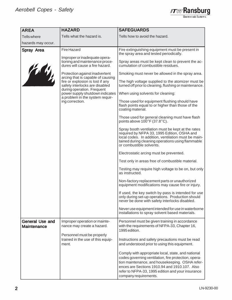
Spray AreaSpray AreaSpray AreaSpray AreaSpray Area
Improper operation or mainte-nance may create a hazard.
Personnel must be properlytrained in the use of this equip-ment.
Personnel must be given training in accordancewith the requirements of NFPA-33, Chapter 16,1995 edition.
Instructions and safety precautions must be readand understood prior to using this equipment.
Comply with appropriate local, state, and nationalcodes governing ventilation, fire protection, opera-tion maintenance, and housekeeping. OSHA refer-ences are Sections 1910.94 and 1910.107. Alsorefer to NFPA-33, 1995 edition and your insurancecompany requirements.
General Use andGeneral Use andGeneral Use andGeneral Use andGeneral Use andMaintenanceMaintenanceMaintenanceMaintenanceMaintenance
Fire Hazard
Improper or inadequate opera-tioning and maintenance proce-dures will cause a fire hazard.
Protection against inadvertentarcing that is capable of causingfire or explosion is lost if anysafety interlocks are disabledduring operation. Frequentpower supply shutdown indicatesa problem in the system requir-ing correction.
Fire extinguishing equipment must be present inthe spray area and tested periodically.
Spray areas must be kept clean to prevent the ac-cumulation of combustible residues.
Smoking must never be allowed in the spray area.
The high voltage supplied to the atomizer must beturned off prior to cleaning, flushing or maintenance.
When using solvents for cleaning:
Those used for equipment flushing should haveflash points equal to or higher than those of thecoating material.
Those used for general cleaning must have flashpoints above 100°F (37.8°C).
Spray booth ventilation must be kept at the ratesrequired by NFPA 33, 1995 Edition, OSHA andlocal codes. In addition, ventilation must be main-tained during cleaning operations using flammableor combustible solvents.
Electrostatic arcing must be prevented.
Test only in areas free of combustible material.
Testing may require high voltage to be on, but onlyas instructed.
Non-factory replacement parts or unauthorizedequipment modifications may cause fire or injury.
If used, the key switch by-pass is intended for useonly during set-up operations. Production shouldnever be done with safety interlocks disabled.
Never use equipment intended for use in waterborneinstallations to spray solvent based materials.
22222

LN-9230-00
Aerobell Copes - Safety
AREAAREAAREAAREAAREA
Tells where
hazards may occur.
HAZARDHAZARDHAZARDHAZARDHAZARD
Tells what the hazard is.
SAFEGUARDSSAFEGUARDSSAFEGUARDSSAFEGUARDSSAFEGUARDS
Tells how to avoid the hazard.
ElectricalElectricalElectricalElectricalElectricalEquipmentEquipmentEquipmentEquipmentEquipment
High voltage equipment is uti-lized. Arcing in areas of flam-mable or combustible materialsmay occur. Personnel are ex-posed to high voltage duringoperation and maintenance.
Protection against inadvertentarcing that may cause a fire orexplosion is lost if safety circuitsare disabled during operation.
Frequent power supply shut-down indicates a problem in thesystem which requires correc-tion.
An electrical arc can ignite coat-ing materials and cause a fire orexplosion.
The power supply, optional remote control cabinet,and all other electrical equipment must be locatedoutside Class I or II, Division 1 and 2 hazardousareas. Refer to NFPA No. 33, 1995 Edition.
Turn the power supply OFF before working on theequipment.
Test only in areas free of flammable or combus-tible material.
Testing may require high voltage to be on, but onlyas instructed.
Production should never be done with the safetycircuits disabled.
Before turning the high voltage on, make sure noobjects are within the sparking distance.
Explosion Hazard /Explosion Hazard /Explosion Hazard /Explosion Hazard /Explosion Hazard /IncompatibleIncompatibleIncompatibleIncompatibleIncompatibleMaterialsMaterialsMaterialsMaterialsMaterials
Halogenated hydrocarbon solventsfor example: methylene chlorideand 1,1,1,-Trichloroethane are notchemically compatible with thealuminum that might be used inmany system components. Thechemical reaction caused by thesesolvents reacting with aluminumcan become violent and lead to anequipment explosion.
Aluminum is widely used in other spray applicationequipment - such as material pumps, regulators,triggering valves, etc. Halogenated hydrocarbonsolvents must never be used with aluminum equip-ment during spraying, flushing, or cleaning. Readthe label or data sheet for the material you intendto spray. If in doubt as to whether or not a coatingor cleaning material is compatible, contact yourmaterial supplier. Any other type of solvent maybe used with aluminum equipment.
Toxic SubstancesToxic SubstancesToxic SubstancesToxic SubstancesToxic Substances Certain material may be harmfulif inhaled, or if there is contactwith the skin.
Follow the requirements of the Material SafetyData Sheet supplied by coating material manufac-turer.
Adequate exhaust must be provided to keep the airfree of accumulations of toxic materials.
Use a mask or respirator whenever there is achance of inhaling sprayed materials. The maskmust be compatible with the material being spray-ed and its concentration. Equipment must be asprescribed by an industrial hygienist or safety ex-pert, and be NIOSH approved.
33333

LN-9230-00
Aerobell Copes - Safety
AREAAREAAREAAREAAREA
Tells where
hazards may occur.
HAZARDHAZARDHAZARDHAZARDHAZARD
Tells what the hazard is.
SAFEGUARDSSAFEGUARDSSAFEGUARDSSAFEGUARDSSAFEGUARDS
Tells how to avoid the hazard.
Spray Area /Spray Area /Spray Area /Spray Area /Spray Area /High VoltageHigh VoltageHigh VoltageHigh VoltageHigh VoltageEquipmentEquipmentEquipmentEquipmentEquipment
This is a high voltage un-grounded device that can pro-duce electrical arcs capable ofigniting coating materials.
Parts being sprayed must be supported on conveyorsor hangers and be grounded. The resistance betweenthe part and ground must not exceed 1 megohm.(Reference NFPA Bulletin No. 33, 1995 Edition.)
A safe distance must be maintained between theparts being coated and the atomizer bell. A distanceof at least 1 inch for each 10 KV of power supplyoutput voltage is required at all times.
Parts must be supported so that they will not swingand reduce the clearance specified above.
All electrically conductive objects in the spray area,with the exception of those objects required by theprocess to be at high voltage, must be grounded.
Unless specifically approved for use in hazardouslocations, the power supply and other electricalequipment must not be used in Class I, Division 1 or2 locations.
Personnel Safety /Personnel Safety /Personnel Safety /Personnel Safety /Personnel Safety /Mechanical HazardsMechanical HazardsMechanical HazardsMechanical HazardsMechanical Hazards
The atomizer can rotate at speedsup to 30,000 (disk) and 55,000RPM (bells). At these speeds, theedge of the applicator can easilycut into skin. Loose articles canalso be caught by the rotating bell.
Personnel must stay clear of the bell whenever it isrotating.
Before touching the bell, the turbine air must beshut off.
If the bell has been rotating, allow at least two min-utes for it to come to a complete stop beforetouching it.
Personnel SafetyPersonnel SafetyPersonnel SafetyPersonnel SafetyPersonnel Safety Skin puncturing by sharpelectrode.
Take precautions to see that flesh is not puncturedby sharp electrode.
Intended UseIntended UseIntended UseIntended UseIntended Use Using coating materials and/orcleaning and flushing solventswhich have flash points below100°F (37.8°C) may cause a firehazard.
This system is intended for use with waterbornecoating formulations only.
44444

LN-9230-00
NOTES:NOTES:NOTES:NOTES:NOTES:
Aerobell Copes - Safety
55555

LN-9230-00
Aerobell Copes - Introduction
FEAFEAFEAFEAFEATURESTURESTURESTURESTURES• Aerobell quick change turbine motor.• Retaining nut for fast replacement of the ro-
tary atomizer assembly.• Center mounting of rotary atomizer.• Indirect (external) charge for use with
grounded, waterborne systems.• Optional direct charge for use with isolated,
waterborne systems (electrodes removed).• Optional direct charge for use with grounded,
solventborne systems (electrodes removed).
GENERAL DESCRIPTIONGENERAL DESCRIPTIONGENERAL DESCRIPTIONGENERAL DESCRIPTIONGENERAL DESCRIPTION
Aerobell Copes is a indirect (external) chargingelectrostatic applicator for use with groundedwaterborne fluid systems. Indirect charging,known as ion bombardment, is a proven methodof electrostatically charging waterborne materialwithout the need of isolating the fluid system.
High voltage is applied to the six probes (elec-trode) assemblies located on the exterior of thebell assembly. Paint is atomized by the ground-ed bell cup and the electrostatic charge isapplied to the atomized paint particles during thetransfer to a grounded work piece via the elec-trostatic field generated from the six probes.
INTRODUCTIONINTRODUCTIONINTRODUCTIONINTRODUCTIONINTRODUCTION
Turbine Speed:Turbine Speed:Turbine Speed:Turbine Speed:Turbine Speed: 10,000-50,000 rpm60,000 rpm max.intermittent
Turbine Type:Turbine Type:Turbine Type:Turbine Type:Turbine Type: Impulse
Weight:Weight:Weight:Weight:Weight: 14.2 lbs.
Length:Length:Length:Length:Length: 14 in.
Diameter:Diameter:Diameter:Diameter:Diameter: 7-7/8 in. @ ElectrodeCenter
Turbine Air:Turbine Air:Turbine Air:Turbine Air:Turbine Air: 45 psi max. 18 scfm
Bearing Air:Bearing Air:Bearing Air:Bearing Air:Bearing Air: 60 psi min. / 100 psi max.2-3 scfm@80 psi
Shaping Air:Shaping Air:Shaping Air:Shaping Air:Shaping Air: 60 psi max.
Brake Air:Brake Air:Brake Air:Brake Air:Brake Air: 100 psi max.
Fluid Delivery:Fluid Delivery:Fluid Delivery:Fluid Delivery:Fluid Delivery: 400 cc/min. max.
Atomization Pattern:Atomization Pattern:Atomization Pattern:Atomization Pattern:Atomization Pattern: 15 in. - 48 in.
Rotary AtomizerRotary AtomizerRotary AtomizerRotary AtomizerRotary AtomizerChange Time:Change Time:Change Time:Change Time:Change Time: Approx. 40 sec.
Bell Change Time:Bell Change Time:Bell Change Time:Bell Change Time:Bell Change Time: Approx. 40 sec.
Bell Cleaning Time:Bell Cleaning Time:Bell Cleaning Time:Bell Cleaning Time:Bell Cleaning Time: Approx. 2-3 sec.(Solvent Flush)(Solvent Flush)(Solvent Flush)(Solvent Flush)(Solvent Flush)
Rotational SpeedRotational SpeedRotational SpeedRotational SpeedRotational SpeedControl EmitterControl EmitterControl EmitterControl EmitterControl EmitterType:Type:Type:Type:Type: Magnetic
SPECIFICASPECIFICASPECIFICASPECIFICASPECIFICATIONSTIONSTIONSTIONSTIONS
MechanicalMechanicalMechanicalMechanicalMechanical
Power Supply Type:Power Supply Type:Power Supply Type:Power Supply Type:Power Supply Type: RansPak 1000
Charging Method:Charging Method:Charging Method:Charging Method:Charging Method: Indirect, Grounded Fluid
Output Voltage:Output Voltage:Output Voltage:Output Voltage:Output Voltage: Voltage Regulation ModeSet Point (70 kV) max.
Output Current:Output Current:Output Current:Output Current:Output Current: Current Regulation ModeSet Points (0-300) µA
Turbine SpeedTurbine SpeedTurbine SpeedTurbine SpeedTurbine SpeedControl:Control:Control:Control:Control: Eurocard Atomizer
Module
Shaping Air Control:Shaping Air Control:Shaping Air Control:Shaping Air Control:Shaping Air Control: Eurocard Analog Module
ElectricalElectricalElectricalElectricalElectrical
66666

LN-9230-00
Aerobell Copes - Introduction
77777
Complete StandardComplete StandardComplete StandardComplete StandardComplete Standard
ModelsModelsModelsModelsModels
AEROBELL COPES MODELSAEROBELL COPES MODELSAEROBELL COPES MODELSAEROBELL COPES MODELSAEROBELL COPES MODELS
Figure 1: ModelsFigure 1: ModelsFigure 1: ModelsFigure 1: ModelsFigure 1: Models
75850-0275850-0375850-1275850-1375850-2275850-23
Quick Change MotorQuick Change MotorQuick Change MotorQuick Change MotorQuick Change Motor
AssemblyAssemblyAssemblyAssemblyAssembly
(Included)
76746-20276746-20376746-10276746-10376746-30276746-303
76746-202
76746-102
76746-302
76746-203
76746-103
76746-303
QuickQuickQuickQuickQuick
ChangeChangeChangeChangeChange
PartPartPartPartPart
NumberNumberNumberNumberNumber
AEROBELL COPESAEROBELL COPESAEROBELL COPESAEROBELL COPESAEROBELL COPESOPTION & REPLACEMENT ITEMSOPTION & REPLACEMENT ITEMSOPTION & REPLACEMENT ITEMSOPTION & REPLACEMENT ITEMSOPTION & REPLACEMENT ITEMS
Figure 2: Options / ReplacementsFigure 2: Options / ReplacementsFigure 2: Options / ReplacementsFigure 2: Options / ReplacementsFigure 2: Options / Replacements
76747-01
76747-02
Air BearingAir BearingAir BearingAir BearingAir Bearing
TurbineTurbineTurbineTurbineTurbine
ModelModelModelModelModel
NumberNumberNumberNumberNumber
Fluid Tube IDFluid Tube IDFluid Tube IDFluid Tube IDFluid Tube ID
Size & PartSize & PartSize & PartSize & PartSize & Part
NumberNumberNumberNumberNumber
RPM-440(3/32) .093(Viscosity 25-35sec. #4 Ford @30 psi) mediumrange materials.
RPM-441(1/16) .062(Viscosity 10-20sec. #4 Ford @ 30psi) light rangematerials.
RPM-439(1/8) .125(Viscosity 30-50sec. #4 Ford @ 30psi) heavy rangematerials.
AEROBELL COPESAEROBELL COPESAEROBELL COPESAEROBELL COPESAEROBELL COPESMODELMODELMODELMODELMODEL IDENTIFICA IDENTIFICA IDENTIFICA IDENTIFICA IDENTIFICATIONTIONTIONTIONTION
7674676746767467674676746 - - - - - XXXXX - - - - - XXXXXXXXXX
Basic PartBasic PartBasic PartBasic PartBasic PartNumberNumberNumberNumberNumber
Fluid Tube TypeFluid Tube TypeFluid Tube TypeFluid Tube TypeFluid Tube Type1 = RPM-441 (1/16 I.D.)2 = RPM-440 (3/32 I.D.)3 = RPM-439 (1/8 I.D.)
Bell Cup TypeBell Cup TypeBell Cup TypeBell Cup TypeBell Cup Type
Figure 3: Model IdentificationFigure 3: Model IdentificationFigure 3: Model IdentificationFigure 3: Model IdentificationFigure 3: Model Identification
03 = LRPM-4001-00, 70mm bell cup, for use with;Part #Part #Part #Part #Part # Description Qty Req'd.Description Qty Req'd.Description Qty Req'd.Description Qty Req'd.Description Qty Req'd.76747-02 Turbine Motor Assy 176632-00 Shaping Air Ring Cap 176631-00 Shaping Air Ring 1LRPM0112-00 Seal Adapter 1LRPM0111-00 Seal 17554-105 O-Ring 1
02 = RPM-457, 57mm bell cup, for use with;Part #Part #Part #Part #Part # Description Qty Req'd.Description Qty Req'd.Description Qty Req'd.Description Qty Req'd.Description Qty Req'd.76747-01 Turbine Motor Assy 176757-00 Shaping Air Ring Cap 176756-00 Shaping Air Ring 1RPM-2 Seal 1

LN-9230-00
> Air must be properly filtered to assureextended turbine life and to prevent con-tamination of the paint job. Air which is notadequately filtered will foul the turbine airbearings and cause turbine failure. Thecorrect type of filters must be used in anAerobell Copes system. The filter elementsmust be replaced on a regular schedule toassure clean air.
AIR FILAIR FILAIR FILAIR FILAIR FILTRATRATRATRATRATIONTIONTIONTIONTIONREQUIREMENTSREQUIREMENTSREQUIREMENTSREQUIREMENTSREQUIREMENTSIt is the user's responsibility to insure clean, dryair at all times. Turbine failure resulting fromcontaminated air will not be covered underwarranty. The following pre-filter and bearing airfilter(s) (see Figure 5) are recommended for usein Aerobell Copes systems. See Figure 5 ifother filters are incorporated in the system - thefilters to be used mustmustmustmustmust have filtering capacitiesequal to or greater than those shown in Figure5.
PSI RPM (unloaded) SCFMPSI RPM (unloaded) SCFMPSI RPM (unloaded) SCFMPSI RPM (unloaded) SCFMPSI RPM (unloaded) SCFM
45403530252015105
60,000 (max.)56,00052,60048,30043,40037,70031,00023,00013,000
18.015.814.213.011.49.77.96.13.9
Figure 4: Turbine Air Pressure / RPM / SCFMFigure 4: Turbine Air Pressure / RPM / SCFMFigure 4: Turbine Air Pressure / RPM / SCFMFigure 4: Turbine Air Pressure / RPM / SCFMFigure 4: Turbine Air Pressure / RPM / SCFM
Aerobell Copes - Introduction
C A U T I O NC A U T I O NC A U T I O NC A U T I O NC A U T I O N!!!!!
88888
ITW RansburgITW RansburgITW RansburgITW RansburgITW RansburgFilter Model No.Filter Model No.Filter Model No.Filter Model No.Filter Model No.
HAF-503
RPM-417
RPM-418
HAF-15 Element, One
RPM-32 Elements,Carton of 4
RPM-33 Elements,Carton of 8
Pre-filter, removes coarse amounts of oil, moisture& dirt. Used upstream of RPM-417 pre-filter (usedin systems with poor air quality).
Pre-filter, coalescing type, 136 scfm, 98.5% efficiencyparticulate removal .3 to .6 micron, max. aerosol passed1.0 micron, max. solid passed .4 micron (dependentupon scfm requirement per applicator).
Bearing air filter, coalescing type, 19 scfm, 99.995%efficiency particulate removal .3 to .6 micron, max.aerosol passed .6 micron, max. solid passed .2 micron(one per applicator).
Description / SpecificationsDescription / SpecificationsDescription / SpecificationsDescription / SpecificationsDescription / SpecificationsReplacementReplacementReplacementReplacementReplacementElement Part No.Element Part No.Element Part No.Element Part No.Element Part No.
Figure 5a: Aerobell Copes Models Recommended Air FiltrationFigure 5a: Aerobell Copes Models Recommended Air FiltrationFigure 5a: Aerobell Copes Models Recommended Air FiltrationFigure 5a: Aerobell Copes Models Recommended Air FiltrationFigure 5a: Aerobell Copes Models Recommended Air Filtration

LN-9230-00
Aerobell Copes - Introduction
99999
Figure 5b: Aerobell Copes Models Recommended Air FiltrationFigure 5b: Aerobell Copes Models Recommended Air FiltrationFigure 5b: Aerobell Copes Models Recommended Air FiltrationFigure 5b: Aerobell Copes Models Recommended Air FiltrationFigure 5b: Aerobell Copes Models Recommended Air Filtration

LN-9230-00
Aerobell Copes - Installation
INSTINSTINSTINSTINSTALLAALLAALLAALLAALLATIONTIONTIONTIONTION
AIR & FLUID CONNECTIONSAIR & FLUID CONNECTIONSAIR & FLUID CONNECTIONSAIR & FLUID CONNECTIONSAIR & FLUID CONNECTIONS
See Figure 6 for rear views of the AerobellCopes manifolds. Refer to this figure for properlocation of connections.
The Aerobell Copes shipping container includesthe basic atomizer assembly with bell and manifold.
Service tools required with the system are 2 (ormore) RPM-419 (wrenches) per bell spray zoneor spray station. (These service tools must(These service tools must(These service tools must(These service tools must(These service tools mustbe purchased separately.) be purchased separately.) be purchased separately.) be purchased separately.) be purchased separately.) These are requiredto remove the bell cup. Also required with thesystem is 1 (or more) 75852-00 (retaining nuttool) per zone which are used to remove thequick change Aerobell assembly.
Mount the Aerobell Copes securely to a stationary,reciprocating or oscillating fixture using (Qty-4)5/16-18 plastic (nonconductive) mounting screws.
> Risk of arcing / fire hazard. The AerobellCopes must be located a safe distance fromthe object to be sprayed, as well as all othergrounded objects. The safe distance is atleast 1 inch per 10 kV of applied electrostat-ic voltage. Example: If the Aerobell Copesis used with 70 kV applied voltage, theelectrode tips must be at least 7 inches fromthe object being sprayed.
AIR FILAIR FILAIR FILAIR FILAIR FILTER INSTTER INSTTER INSTTER INSTTER INSTALLAALLAALLAALLAALLATIONTIONTIONTIONTIONThe following guidelines mustmustmustmustmust be observed wheninstalling air filters for the Aerobell Copes system:(See Figure 5 for additional information.)
1. Use only recommended pre-filterspre-filterspre-filterspre-filterspre-filters andbearing air filtersbearing air filtersbearing air filtersbearing air filtersbearing air filters as shown in Figure 5.Additional system air filtration (i.e. refrig-erated air dryer) may also be used if de-sired.
2. Use one bearing air filterbearing air filterbearing air filterbearing air filterbearing air filter per AerobellCopes.
3. Mount the bearing air filterbearing air filterbearing air filterbearing air filterbearing air filter as close aspossible to the Aerobell Copes (do notdo notdo notdo notdo notmountmountmountmountmount further than 30 ft. away).
4. Where possible, the pre-filterpre-filterpre-filterpre-filterpre-filter(s) andbearing air filterbearing air filterbearing air filterbearing air filterbearing air filter(s) should be mountedwhere they can be easily seen so thatoperating personnel can observe anddetermine when maintenance is re-quired.
5. Standard black iron or galvanized pipingmay be used priorpriorpriorpriorprior to the HAF-503 orRPM-417 pre-filters only. All piping afterthe pre-filter should be brass, stainlesssteel, aluminum, or hose (poly, nylon,nyliner, etc.).
6. Do notnotnotnotnot use teflon tape, pipe dope, orother thread sealant downstream of thebearing air filterbearing air filterbearing air filterbearing air filterbearing air filter. Loose flakes of teflontape or other sealant can break looseand plug the very fine air holes in the tur-bine bearings.
7. Use clear see-through air tubing be-tween the bearing air filterbearing air filterbearing air filterbearing air filterbearing air filter and bearingair fitting to clearly indicate if oil or mois-ture contamination is getting past the fil-ter.
8. If air heaters are used in the system (toeliminate excessive in-line humidityconditions) and the heated air will ex-ceed 120°F, the heaters must be locatedafter all filters to prevent damage to thefilter media.
> Arcing / fire hazard exists if un-grounded metal connections (air or fluid)are used in the spray area. Use plasticnonconductive connections, or ensuremetal connections are at ground potential.
W A R N I N GW A R N I N GW A R N I N GW A R N I N GW A R N I N G!!!!!
W A R N I N GW A R N I N GW A R N I N GW A R N I N GW A R N I N G!!!!!
1010101010

LN-9230-00
TUBE CONNECTIONSTUBE CONNECTIONSTUBE CONNECTIONSTUBE CONNECTIONSTUBE CONNECTIONS
See Figure 6 for rear views of the AerobellCopes manifolds. Refer to this figure for properlocation of connections.
Figure 6: Tube Connector Information / Aerobell CopesFigure 6: Tube Connector Information / Aerobell CopesFigure 6: Tube Connector Information / Aerobell CopesFigure 6: Tube Connector Information / Aerobell CopesFigure 6: Tube Connector Information / Aerobell Copes
Bearing Air (BRG)
Turbine Air (DRV)
Shaping Air (SHP)
Brake Air (BRK)
Fluid Inlet (FLD)
Tube Connector InformationTube Connector InformationTube Connector InformationTube Connector InformationTube Connector Information
LSFI0025-13Connector, Male Tube1/4 O.D. Tube x 1/4 NPT
LSFI0025-27Connector, Male Tube1/2 O.D. Tube x 3/8 NPT
LSFI0025-21Connector, Male Tube3/8 O.D. Tube x 1/4 NPT
LSFI0025-21Connector, Male Tube3/8 O.D. Tube x 1/4 NPT
LSFI0022-04Union, 37° Flared Tube(AN Size)
BEARING AIRBEARING AIRBEARING AIRBEARING AIRBEARING AIR
Using 1/4" O.D. x 1/16" wall tubing (clear see-through), connect a properly filtered air sourceto the fitting marked “BRG” on the manifold.(See Figure 6.) It is recommended to use clear(see through) tubing for bearing air so that anycontamination that gets past the final bearing airfilter will be apparent.
Under the “Operation” section which follows,there is a Caution regarding bearing damage ifthe turbine is running while bearing air is OFF.Since the turbine must not be operated withoutfirst turning ON bearing air, some means of as-suring the presence of bearing air before turningthe turbine “On” must be provided. One methodis by interlocking the turbine drive air to thebearing air (i.e. with an air piloted valve).
> Do not use teflon tape or pipe dope onany air fittings beyond the final air filter forbearing air. The tape or dope may breakfree and cause plugging of the turbine airbearings, and result in turbine failure.
> Provisions should also be made toassure bearing air remains ON during thecoast down period when turbine air isturned OFF. (See "Specifications" onpage 6.)
C A U T I O NC A U T I O NC A U T I O NC A U T I O NC A U T I O N!!!!!
C A U T I O NC A U T I O NC A U T I O NC A U T I O NC A U T I O N!!!!!
Aerobell Copes - Installation
1111111111

LN-9230-00
Aerobell Copes - Installation
1212121212
SHAPING AIRSHAPING AIRSHAPING AIRSHAPING AIRSHAPING AIR
Use 3/8" O.D. x 1/16" wall tubing. Connectshaping air source to the fitting marked “SHP”on the manifold. (See Figure 6.)
BRAKE AIRBRAKE AIRBRAKE AIRBRAKE AIRBRAKE AIR
Use 3/8" O.D. x 1/16" wall tubing. Connectbrake air source to the fitting marked “BRK” onthe manifold. See Figure 6.
> If the brake air feature is not used, thefitting supplied from the factory must bereplaced using a plastic (non-conductive)1/4 NPT pipe plug SSP-1425 or equiva-lent.
The plug is used to keep contaminationout of the unit and prevent air leakage.
TURBINE AIRTURBINE AIRTURBINE AIRTURBINE AIRTURBINE AIR
Using 1/2" O.D. x 1/16" wall tubing. Connectturbine air source to the fitting marked “DRV” onthe manifold. See Figure 6.
FLUID INLETFLUID INLETFLUID INLETFLUID INLETFLUID INLET
Use 1/4" O.D. x 1/16" wall tubing. Connect fluidsource to the fitting marked “FLD” on the mani-fold. See Figure 6.
> If the coating material being used isheated, check the max. rated tempera-ture for the fluid tubing to be used. Poly-ethylene tubing (9704-03) is rated for amax. of 80°F (27°C). Nylon tubing (7113-11) is rated for 200°F (95°C) max.
HIGH VOLHIGH VOLHIGH VOLHIGH VOLHIGH VOLTTTTTAGEAGEAGEAGEAGE
Use SSW-1064 high voltage cable and 6287-00,(Qty-2) high voltage tacks, pressed into eachend of cable. Connect high voltage cable to theport marked “HV” on the manifold. (See Figure6.)
GROUNDGROUNDGROUNDGROUNDGROUND
Use SSW-1064, high voltage cable, and 6287-00, (Qty-1) high voltage tack, pressed into oneend of cable. Strip opposite end and connect toearth ground. Connect ground source to theport marked “GND” on the manifold. (See Fig-ure 6.)
AEROBELL COPESAEROBELL COPESAEROBELL COPESAEROBELL COPESAEROBELL COPESSYSTEM INTERLOCKSSYSTEM INTERLOCKSSYSTEM INTERLOCKSSYSTEM INTERLOCKSSYSTEM INTERLOCKS
The following system interlocks are required toprevent equipment damage:
1. System interlock that would shut OFFall applicator pneumatic controls if bear-ing air is disabled. Bearing air shouldremain ON at all times and should beshut OFF only by turning OFF the mainair to the pneumatic control cabinet.
The exhaust from the bearing air is posi-tive pressure acting as a seal air thatmay aid in keeping contaminates fromentering the turbine assembly. Bearingair should only be disabled for applicatoroff-line (out-of-booth) maintenance andonly after the "coast down" time of threeminutes.
NOTENOTENOTENOTENOTE
NOTENOTENOTENOTENOTE
> When the turbine air is turned OFF,the turbine will continue to operate or"coast down" for about two minutes.Provisions should be made to assure thatthe operator waits at least three minutes,after shutting OFF the turbine air, beforeshutting OFF the main air supply.
C A U T I O NC A U T I O NC A U T I O NC A U T I O NC A U T I O N!!!!!

LN-9230-00
Aerobell Copes - Installation
1313131313
2. System interlock that would allow fluidflow only when the bell cup is spinning(turbine drive air ON) and must be shutOFF if turbine drive air is lost or dis-abled. It should not be possible for thecoating material to be sprayed unlessthe turbine is spinning or in bypassmode for checking fluid deliveries.
> The bell assembly must be removedwhen making fluid flow checks. If thepaint is turned ON when the bell is mount-ed on the motor shaft and not rotating,paint will enter the shaft and possiblydamage the air bearing. Normally pneu-matic interlocks will not allow the paint totrigger ON when the turbine air is OFF.
C A U T I O NC A U T I O NC A U T I O NC A U T I O NC A U T I O N!!!!!
> The coating material must never beturned ON unless the bell cup is mountedon the motor shaft and rotating at a speedhigh enough to ensure dissipation of allmaterial supplied.
W A R N I N GW A R N I N GW A R N I N GW A R N I N GW A R N I N G!!!!!
3. System interlock that would shut OFFthe supply of drive air to the turbine ifbearing air is lost or falls below 60psi atthe applicator. If bearing air drops below60psi at the turbine, the turbine drive airwill automatically shut OFF. A bearingair return connection is provided at theapplicator and is used to supply a signalto the pneumatic interlock located in theatomizer module or equivalent. Theports are interconnected so either maybe used for supply or return to the aircontrol cabinet.
> Operating the turbine with bearing airpressure below 60psi (measured atturbine inlet) may cause bearing damage.
C A U T I O NC A U T I O NC A U T I O NC A U T I O NC A U T I O N!!!!!
4. System interlock that would not allowthe turbine to exceed the maximumrated intermittent speed and shut OFFturbine drive air if fiber optic feedback islost or disabled when used with closedloop speed control system. The air inletpressure determines the speed of theturbine and excessive speed will causeair turbine damage.
> Pneumatic input to the turbine air inletmust be controlled and prevent the turbinefrom exceeding the maximum ratedintermittent speed of 60,000rpm. (See"Specifications" on page 6.)
W A R N I N GW A R N I N GW A R N I N GW A R N I N GW A R N I N G!!!!!
5. If the Aerobell Copes unit is mountedwith the bell cup facing up, a deviceshould be provided to rotate the applica-tor into a horizontal position during main-tenance.

LN-9230-00
> Operators must be fully trained in safeoperation of electrostatic equipment.Operators must read all instructions andsafety precautions prior to using thisequipment. (Ref. NFPA-33 / 1995 edition,Ch 16.)
TURBINE SPEEDTURBINE SPEEDTURBINE SPEEDTURBINE SPEEDTURBINE SPEEDThe speed of the turbine is determined by the airinlet pressure. See Figure 4 “TURBINE AIRPRESSURE/RPM/SCFM,” under Air FiltrationRequirements section for more information. Thedesired speed will depend upon the type ofcoating material and various application require-ments.
> Excessive speed will cause air turbinedamage. Do not exceed the maximumrated intermittent speed of 60,000 rpm.
Turbine speed may be controlled by use of op-tional PulsetrackTM or eurocard atomizer modulespeed monitor and control. Contact your ITWRansburg representative for more informationon this optional equipment.
Bearing damage (and subsequent turbine fail-ure) caused by running the turbine without bear-ing air will not be covered under ITW Ransburgwarranty.
OPERAOPERAOPERAOPERAOPERATIONTIONTIONTIONTION
BEARING AIRBEARING AIRBEARING AIRBEARING AIRBEARING AIR
> Air bearing air must be ON wheneverthe turbine is operated. If not, severebearing damage will occur. It is recom-mended to leave bearing air ON at alltimes. During maintenance or disassem-bly, turbine air must be OFF for at least 3minutes before shutting OFF bearing airor main line air.
Nominal bearing air pressure is 80 psi, with anoperating range of 60 psi minimum to 100 psimaximum. Under no circumstances should theturbine be operated with less than 60 psi bear-ing air pressure.
> Operating the turbine with bearing airpressure below 60 psi (measured atturbine inlet) may cause bearing damage.
BRAKE AIRBRAKE AIRBRAKE AIRBRAKE AIRBRAKE AIRBrake air is used to slow the turbine speed. It isadvantageous for short color change cycletimes and may be used for stopping the turbine.Use of the brake involves (1) turning OFF tur-bine drive air, and then (2) turning the brake airON for a short duration. For example, the airbrake will reduce the turbine speed as shown inFigure 7.
Figure 7: Braking TimeFigure 7: Braking TimeFigure 7: Braking TimeFigure 7: Braking TimeFigure 7: Braking Time(At 90 psi Brake Air Pressure)(At 90 psi Brake Air Pressure)(At 90 psi Brake Air Pressure)(At 90 psi Brake Air Pressure)(At 90 psi Brake Air Pressure)
To Brake FromTo Brake FromTo Brake FromTo Brake FromTo Brake From
(RPM)(RPM)(RPM)(RPM)(RPM)
60,000 to 40,00060,000 to 20,00060,000 to 040,000 to 20,00040,000 to 0
SecondsSecondsSecondsSecondsSeconds
(Approx.)(Approx.)(Approx.)(Approx.)(Approx.)
3.7 7.512.9 4.0 9.0
W A R N I N GW A R N I N GW A R N I N GW A R N I N GW A R N I N G!!!!!
C A U T I O NC A U T I O NC A U T I O NC A U T I O NC A U T I O N!!!!!
C A U T I O NC A U T I O NC A U T I O NC A U T I O NC A U T I O N!!!!!
C A U T I O NC A U T I O NC A U T I O NC A U T I O NC A U T I O N!!!!!
Aerobell Copes - Operation
1414141414
> Never over brake allowing the bell cupto spin the opposite direction of driverotation (CCW) facing the bell cup.
C A U T I O NC A U T I O NC A U T I O NC A U T I O NC A U T I O N!!!!!
When turning the turbine ON, bearing air mustbe present. Likewise, bearing air must remainON when the turbine air is turned OFF until theturbine stops spinning. Never turn OFF bearingair to cause the turbine to stop spinning. Brakeair can be used to slow the turbine (see nextsection on Brake Air), wait for the turbine to stopspinning before turning bearing air OFF.

LN-9230-00
ELECTROSTELECTROSTELECTROSTELECTROSTELECTROSTAAAAATIC VOLTIC VOLTIC VOLTIC VOLTIC VOLTTTTTAGEAGEAGEAGEAGE
The RansPak 1000 power supply and controlunit are recommended for use with the AerobellCopes applicator. The output voltage can becontrolled by one of two modes: Either modecan be adjusted from the controller's front panelor through a programmable controller.
To maintain the highest transfer efficiency, it iscritical to determine the optimum (maximize)high voltage output without creating a high volt-age overload.
Current Regulation ModeCurrent Regulation ModeCurrent Regulation ModeCurrent Regulation ModeCurrent Regulation ModeThe voltage is controlled using current regula-tion, allowing the voltage to vary while maintain-ing the desired current set point of 0-300 micro-amps.
Voltage Regulation ModeVoltage Regulation ModeVoltage Regulation ModeVoltage Regulation ModeVoltage Regulation ModeThe voltage is controlled using voltage regula-tion, allowing the current to vary while maintain-ing the desired voltage set point of 0-70 kV.
The actual settings will depend upon variouscoating application requirements and must notexceed 70 kV or 300 micro-amps during normaloperating conditions.
SHAPING AIRSHAPING AIRSHAPING AIRSHAPING AIRSHAPING AIR
Shaping air is used to shape the spray pattern.The lower the pressure, the wider the patternand conversely, higher pressures result innarrower patterns. Shaping air does not helpatomize the material, but does assist in the pen-etration of atomized particles into cavity areas.Shaping air should be kept at a minimum, con-sistent with coating requirements. Excessiveshaping air may assist some atomized paintparticles to blow by the target not allowing full“wrap”, or causing paint particles to bounceback onto the atomizer.
TTTTTARGETARGETARGETARGETARGET DIST DIST DIST DIST DISTANCEANCEANCEANCEANCE
The distance from the Aerobell atomizer to tar-get affects the spray application. For instance,closer distances give a smaller spray pattern
Aerobell Copes - Operation
1515151515
> Risk of arcing/fire hazard. The Aerobellmust be located a safe distance from theobject to be sprayed, as well as all othergrounded objects. The safe distance is atleast 1 inch per 10 kV of applied electro-static voltage. Example: if the AerobellCopes is used with 70 kV applied voltage,the electrode tips must be at least 7 inchesfrom the object to prevent arcing.
W A R N I N GW A R N I N GW A R N I N GW A R N I N GW A R N I N G!!!!!
and greater efficiency. Increasing the distancewill give a larger pattern and possibly reduceefficiency. If the distance is too great, materialmay “wrap back” on the Aerobell. However,coming too close may cause arcing. See Warn-ing below.
TURBINE AIRTURBINE AIRTURBINE AIRTURBINE AIRTURBINE AIR
If an air heater is used to increase the turbinedrive air inlet temperature, it should be adjustedonly high enough (not to exceed 140° F) to pre-vent condensation from forming on the shroudor at the exhaust ports.
> If the turbine drive air is heated, checkthe maximum rated temperature for the airsupply tubing to be used. 9704-07, poly-ethylene tubing, is rated for a maximum of80° F (27° C). 7113-13, nylon tubing, israted for 200° F (95° C) maximum.
NOTENOTENOTENOTENOTE
> If the thermal insulator and disposablecover are used, a maintenance schedulemust be developed to ensure contami-nated coves are continually replaced anda stockpile of new are kept on hand.
NOTENOTENOTENOTENOTE
The 76739-00, foam insulator, and 76738-00,disposable cover, are used as a thermal insula-tor to prevent condensation from forming on theshroud. The foam insulator and disposablecover may be used in place of air heaters.

LN-9230-00
Aerobell Copes - Operation
ELECTRODE REMOVELECTRODE REMOVELECTRODE REMOVELECTRODE REMOVELECTRODE REMOVALALALALALPROCEDURE FORPROCEDURE FORPROCEDURE FORPROCEDURE FORPROCEDURE FOROPTIONAL DIRECTOPTIONAL DIRECTOPTIONAL DIRECTOPTIONAL DIRECTOPTIONAL DIRECTCHARGING METHODCHARGING METHODCHARGING METHODCHARGING METHODCHARGING METHOD-REFER TO FIGURE 8-REFER TO FIGURE 8-REFER TO FIGURE 8-REFER TO FIGURE 8-REFER TO FIGURE 8
1. Verify that high voltage is OFF. Thehigh voltage must be turned OFF beforeperforming any maintenance.
2. Remove item 7 (13521-03, compressionnut) and high voltage cable from portmarked HV.
3. Remove item 22i (13521-03, compres-sion nut) and ground cable from portmarked GND.
4. Remove item 14 (14061-02, conductivefoam insert), item 13 (76562-00, springloaded contact pin screw assembly),item 12 (75841-00, high voltage cablesupport tube) and item 9 (LSOR0007-06,O-Ring) from port marked HV.
5. Remove item 5 (Qty-6, 75847-00, elec-trode body retaining nuts) and item 6(Qty-6, 76719-00, electrode body as-semblies).
6. Remove item 3 (Qty-20, M5 x 40mmlong, slotted fillister head screws) anditem 4 (Qty-5, 75854-02, 90° connectorelectrode body assembly.) Items 3 and4 (marked “B”) must be removed prior toremoving items 3 and 15 (marked “A”).
7. Remove item 3 (Qty-4, M5 x 40mm long,slotted fillister head screws) and item 15(75854-01, 90° connector electrodebody assembly.) Unit damage may oc-cur if items 3 and 15 (marked “A”) areremoved prior to disassembly of items 9,12, 13 and 14 (marked “C”) and items 3and 4 (marked “B”).
8. Install item 9 (LSOR0007-06, O-Ring),item 12 (75841-00, high voltage cablesupport tube) and item 7 (13521-03,compression nut) into port marked HV.
9. Install 73033-20F, 1/4-28 x 5/8 long ny-lon socket head cap screw (not shown),into item 12 (75841-00, high voltagecable support tube). Torque screw to 3-5 inch pounds.
10. Install 1/4 dia. x 3" long nylon rod (non-conductive) material (not shown) intoitem 12 (75841-00, high voltage cablesupport tube) and tighten item 7 (13521-03, compression nut).
11. Install S10364-00, (Qty-6, 90° connectorport cap, not shown), LSOR0007-05, (Qty-6, o-ring, not shown) and item 3 (Qty-24,M5 x 40mm, long slotted fillister headscrews) in ports marked A and B. Torquescrews to 3-5 inch pounds. Unit damagemay occur if screws are over torqued.
12. Install high voltage cable into port markedGND and tighten item 22i (13521-03,compression nut).
1616161616
COACOACOACOACOATING MATING MATING MATING MATING MATERIALTERIALTERIALTERIALTERIALCONDUCTIVITYCONDUCTIVITYCONDUCTIVITYCONDUCTIVITYCONDUCTIVITYThe Aerobell Copes can be used with a fullrange of conductive coatings including solvent-borne and waterborne materials. Chargingmethods include:
• Indirect charge for use with waterborne,grounded fluid systems. The fluid system,including the applicator, are connected toground potential and voltage is applied to theexternal electrodes. (See Figure 8.)
• Direct charge for use with solventborne,grounded fluid systems with electrodes re-moved. The fluid system is connected toground potential and voltage is applied to theapplicator. (See Figure 8.)
• Direct charge for use with waterborne, iso-lated fluid systems with electrodes removed.The fluid system is isolated from ground po-tential and voltage is applied to the applica-tor. (See Figure 8.)

LN-9230-00
Figure 8: Electrode Removal ProcedureFigure 8: Electrode Removal ProcedureFigure 8: Electrode Removal ProcedureFigure 8: Electrode Removal ProcedureFigure 8: Electrode Removal Procedure
Aerobell Copes - Operation
1717171717

LN-9230-00
Aerobell Copes - Maintenance
MAINTENANCEMAINTENANCEMAINTENANCEMAINTENANCEMAINTENANCE
In addition to the above Warning, which relatesto potential safety hazards, the following infor-mation must be observed to prevent damage tothe equipment.
> Electrical shock/arcing and potentialfire hazards can exist during mainte-nance. The high voltage must be turnedOFF before entering the spray area andperforming any maintenance procedures.Spray booth exhaust fans(s) shouldremain ON while cleaning the equipmentwith solvents.
> Never touch the atomizer bell while itis spinning. The front edge can easily cutinto human skin. Make sure the atomizerbell has stopped spinning before attempt-ing to touch it. Wait at least three minutesafter turbine drive air is OFF beforetouching the bell.
> Do not immerse the Aerobell Copesturbine in solvent or other liquids. Turbinecomponents will be damaged.
> Bearing air must be ON during allcleaning procedures.
> Do not spray the Aerobell Copes unitwith a solvent gun for cleaning. Dousingor spraying the applicator and AerobellCopes components with solvent beforewiping will not help to loosen paint.
The precise sequence of flushing paint from thesystem will vary according to the type of colorvalve arrangement used and other automaticfeatures built into the system. Follow these ba-sic procedures when cleaning:
> Using an atomizer bell with paint buildup will cause a bell imbalance. An imbal-anced bell may cause bearing damageand turbine failure. Also, any paint resi-due caught between the tapered surfacescan prevent the bell from seating properlyand result in an imbalanced condition.
> Never install an atomizer bell onto theshaft without cleaning the fluid tube tip.Paint build-up on the tip may get caught inthe thread relief of the bell during installa-tion.
W A R N I N GW A R N I N GW A R N I N GW A R N I N GW A R N I N G!!!!!
C A U T I O NC A U T I O NC A U T I O NC A U T I O NC A U T I O N!!!!!
C A U T I O NC A U T I O NC A U T I O NC A U T I O NC A U T I O N!!!!!
1818181818
CLEANING PROCEDURESCLEANING PROCEDURESCLEANING PROCEDURESCLEANING PROCEDURESCLEANING PROCEDURES 1. Verify high voltage is OFF. The highvoltage must be turned OFF before per-forming any maintenance.
2. With the bearing air and turbine air ON,flush paint out with solvent. Flushingshould be done before any break in pro-duction. If the Aerobell Copes ismounted facing up, rotate to a horizontalplane before flushing or cleaning.
3. Flushing should be done with the atom-izer bell installed. The bell includes a selfcleaning feature, and the bell will nor-mally be fully cleaned with flushing.However, if there is any remaining paintbuild up on any areas of the bell afterflushing, the bell should be removed andcleaned by hand (see 4 below).
4. Clean the bell by soaking in an appropri-ate solvent as long as necessary toloosen paint. Use a soft bristle brushdipped in solvent to remove paint. Makesure all signs of paint are removed. SeeCaution below. Rinse and dry bell.
5. Before re-installing the bell onto theshaft, check the tapered mating sur-faces of the turbine shaft and bell for anypaint residue. Clean any residue. SeeCaution below.

LN-9230-00
6. Paint or other contamination on the sur-faces of the equipment may cause highvoltage reduction and poor transfer effi-ciency. A schedule must be developedfor equipment maintenance (cleanli-ness). However, care must be takenduring cleaning. The electrode needlemust be straight and sharp. It is recom-mended that the electrode tip be cleanedusing a mild solvent and a soft bristlebrush. Clean the exterior surfaces ofthe Aerobell Copes as follows (seeWarning below).
a). All external surfaces may becleaned using a mild solvent andlint free rags to hand wipe the Aero-bell Copes. Turbine drive air mustbe OFF, but leave shaping air andbearing air ON. Be careful not todrip solvent into the opening behindthe bell. (See step #1.)
b). If conductive, polar solvents areused to clean the Aerobell Copesunit all residue must be removedusing a non-conductive non-polarsolvent. (i.e., high flash naphtha.)(See step #1.)
c). Do not spray the Aerobell Copesunits with a solvent gun used forcleaning. The cleaning fluid underpressure may aid conductive mate-rials to wick into hard to clean ar-eas or may allow fluids to be forcedinto the turbine assembly. (Seestep #1.)
> To reduce the risk of fire or explosion,OSHA and NFPA-33 require that solventsused for exterior cleaning be non-flam-mable (flash points higher than 100°F /37.8°C). Also, since electrostatic equip-ment is involved, these solvents shouldalso be non-polar. Examples of non-flammable, non-polar solvents for wipedown are: amyl acetate, methyl amylacetate, high flash naphtha and mineralspirits.
VIBRAVIBRAVIBRAVIBRAVIBRATION NOISETION NOISETION NOISETION NOISETION NOISE
If the Aerobell Copes is vibrating or making anunusually loud noise, it usually means there isan imbalance situation. The atomizer bell mayhave dried paint on it, or the bell may be physi-cally damaged, or there may be paint trappedbetween the bell and shaft preventing the bellfrom properly seating. If any of these conditionsexist, they mustmustmustmustmust be corrected. Excessive im-balance caused by one of these conditions mayresult in bearing damage and turbine failure.Warranty does notdoes notdoes notdoes notdoes not cover failure caused by im-balanced loading conditions.
To determine if the bell is dirty or damaged, re-move the bell and turn the turbine ON. If thenoise is eliminated, the bell is the problem. If thenoise continues, the turbine may be damagedand should be inspected. Do notnotnotnotnot continue tooperate a noisy turbine.
Aerobell Copes - Maintenance
W A R N I N GW A R N I N GW A R N I N GW A R N I N GW A R N I N G!!!!!
1919191919
7. Do not reuse an atomizer bell thatshows signs of damage such as nicks,heavy scratches, dents, or excessivewear.
PREVENTIVEPREVENTIVEPREVENTIVEPREVENTIVEPREVENTIVEMAINTENANCEMAINTENANCEMAINTENANCEMAINTENANCEMAINTENANCE
Daily MaintenanceDaily MaintenanceDaily MaintenanceDaily MaintenanceDaily Maintenance
• Due to the close proximity of high voltage toground potential, a schedule must be developedfor equipment maintenance (cleanliness).
• Paint within the applicator must be flushedfrom the system prior to any down time or breakin production.
• Verify that high voltage is OFF and that shap-ing air, bearing air and turbine drive air are ON.
• Open the solvent valve, flushing all paint fromthe supply lines and through the atomizer bellassembly.

LN-9230-00
Aerobell Copes - Maintenance
2020202020
> Introducing air which contains oil,moisture and dirt may cause wear anddamage to the bearings. It is the user’sresponsibility to monitor the quality of airand to replace the filter elements as oftenas necessary. Turbine failure caused bypoor air quality will not be covered underwarranty.
Figure 9: Replacement ElementsFigure 9: Replacement ElementsFigure 9: Replacement ElementsFigure 9: Replacement ElementsFigure 9: Replacement Elements
ITW Part#ITW Part#ITW Part#ITW Part#ITW Part#
HAF-15
RPM-32
RPM-33
1
4
8
HAF-503, Pre-Filter
RPM-417, Pre-Filter
RPM-418, BearingAir Filter
Qty. ElementsQty. ElementsQty. ElementsQty. ElementsQty. ElementsPer CartonPer CartonPer CartonPer CartonPer Carton Used OnUsed OnUsed OnUsed OnUsed On
C A U T I O NC A U T I O NC A U T I O NC A U T I O NC A U T I O N!!!!!
• Verify that high voltage is OFF, turbine driveair is OFF, and that the bell cup has stoppedspinning. The bearing air and shaping airshould remain ON.
• Clean all external surfaces of the applicatorusing a lint-free rag dampened with solvent.External surfaces include the quick-change ap-plicator, retaining nut, rear manifold, and elec-trodes.
• After cleaning, all conductive residue must beremoved using a non-conductive solvent.Since electrostatic equipment is involved, thesesolvents should also be non-polar.
> The high voltage must be turned OFFbefore entering the spray area and per-forming any maintenance procedures.Spray booth exhaust fan(s) should remainON while cleaning the equipment withsolvents.
W A R N I N GW A R N I N GW A R N I N GW A R N I N GW A R N I N G!!!!!
Weekly MaintenanceWeekly MaintenanceWeekly MaintenanceWeekly MaintenanceWeekly Maintenance
• Follow all procedures as described underdaily maintenance prior to performing anyweekly maintenance.
• Verify that shaping air is OFF, remove theshaping air ring and cap from the applicator forthorough cleaning.
• Clean the shroud edge, which mates with theshaping air ring taper, using a lint-free ragdampened with solvent.
• Clean the shaping air ring taper, which mateswith the shroud edge, using a soft bristle brushdipped in solvent.
• Clean all external surfaces of the air ring andcap using a lint-free rag dampened with solvent.
• Remove the cap for cleaning inside surfaces.The parts may be soaked in clean solvent only,to loosen paint that has wicked around the cap.
• After removing the cap, use a soft bristlebrush dipped in solvent to clean the grooves,male threads of the air ring, and female threadsof the cap.
• Paint residue found in the shaping air or ex-haust holes is not acceptable and must be re-moved prior to assembly.
• After cleaning, all conductive residue must beremoved using a non-conductive solvent.Since electrostatic equipment is involved, thesesolvents should also be non-polar.
MEAN TIMEMEAN TIMEMEAN TIMEMEAN TIMEMEAN TIMEBETWEEN FBETWEEN FBETWEEN FBETWEEN FBETWEEN FAILUREAILUREAILUREAILUREAILURE
Air Filters / Element ReplacementAir Filters / Element ReplacementAir Filters / Element ReplacementAir Filters / Element ReplacementAir Filters / Element Replacement
ITW Ransburg Aerobell Copes systems includea pre-filter(s) and a final filter for all air to theAerobell Copes unit. The final filter is for bear-ing air only. All filters contain elements thatmust be replaced on a regular basis to assureclean air. RPM-417 and RPM-418 filters alsocontain an automatic drain and pressure differ-ential indicator.

LN-9230-00
Aerobell Copes - Maintenance
2121212121
The pressure differential indicator provides avisual indicator that pops up (becomes morevisible) as the filter element becomes plugged.
Replace the filter elements when the visual indi-cator becomes visible, don’t wait until it pops upfully. As the elements become plugged, theirefficiency drops. The frequency of filter elementchange will depend upon the quality of the plantair. But it is recommended that all elements bereplaced at least every 4 to 6 months.
In plants where heavy amounts of oil and mois-ture vapor are present in the air lines, a refriger-ated air dryer may be necessary.
The Aerobell Copes is designed to give depend-able service and extended life. One of the mostimportant factors in realizing long life is the qual-ity of air. It is therefore essential for the user toclosely monitor the quality of their air and toproperly maintain the air filters by replacing thefilter elements as often as necessary. (Replaceelements at least every 4-6 months or more of-ten.)
MufflerMufflerMufflerMufflerMuffler
Replace the 76310-00, porous plastic muffler, atleast once per year depending upon the applica-tion environment.
Install the porous plastic muffler with the coarse(rough to the touch) side against the 76749-00,mounting ring assembly.
The coarse (rough to the touch) side should al-ways face the direction of air flow.
Plastic HardwarePlastic HardwarePlastic HardwarePlastic HardwarePlastic Hardware
Inspect for broken or loose mounting hardwareevery 4 to 8 weeks. Hardware includes all non-conductive screws used for retaining the 90 de-gree electrodes, rear manifold, and support rod.
The M5 x 40mm long fillister head screw (partnumber 75828-40) used for mounting the 90 de-gree electrodes must be tightened and/or re-placed when broken prior to cleaning. Cleaningsolvents may wick under the electrodes if themounting hardware is not equally tightened.
Shaping Air Ring SealShaping Air Ring SealShaping Air Ring SealShaping Air Ring SealShaping Air Ring Seal
Inspect the shaping air ring seal for damage atthe cupped edge and at the sealing surface ev-ery 12 to 16 weeks or as often as necessary.
The shaping air ring seal (part number RPM-2or LRPM0111-00) is a wear item and must bereplaced if damaged. A damaged seal may af-fect the distribution of shaping air within the airring. Always install the seal with the cuppededge facing forward.
Atomizer Bell AssemblyAtomizer Bell AssemblyAtomizer Bell AssemblyAtomizer Bell AssemblyAtomizer Bell Assembly
Inspect the atomizer bell assembly for any dam-age, wear, or paint build-up every 4 to 8 weeks.
The bell cup is a critical part of the applicatorand is directly responsible for the finish qualityof the product being coated. Replace any atom-izer bell that shows signs of damage such asnicks, heavy scratches, dents, or excessivewear.
Always clean the fluid tube tip before re-install-ing the bell onto the shaft using a lint-free ragdampened with solvent.

LN-9230-00
Copes Quick Change AerobellCopes Quick Change AerobellCopes Quick Change AerobellCopes Quick Change AerobellCopes Quick Change AerobellMotor RemovalMotor RemovalMotor RemovalMotor RemovalMotor Removal
1. Prior to removing the Quick Change Mo-tor Assembly, flush the paint feed lineand bell with solvent. If flushing is notpossible and paint is in the atomizer feedtube, place a rag over the bell end of theatomizer and proceed to step 2.
2. Using 75852-00, retaining nut tool,loosen 75844-00, quick change motorassembly retaining nut. Loosen retain-ing nut CCW to complete thread disen-gagement.
3. While properly supporting the quickchange motor assembly, remove fromthe manifold. Do not allow any paint todrip from the manifold into the air portson the back of the air turbine.
> Be sure to carefully hold the quickchange motor assembly during removal.The quick change motor assembly weighsapproximately 7 lbs and may be droppedand damaged if not properly supported.
C A U T I O NC A U T I O NC A U T I O NC A U T I O NC A U T I O N!!!!!
4. Reinstall 76756-00, shaping air ring, intoshroud. Note that when screwing76756-00 in place, it will become tightafter approximately 2-1/2 turns. At thispoint, use a strap wrench if required, totighten further. The 76756-00 will breakfree and become loose again and canthen be tightened down fully by hand un-til it bottoms against the shroud.
5. Screw 76757-00, shaping air ring cap,onto the 76756-00, shaping air ring, inCW direction. Hand tighten until the ringand cap mating tapered surfaces con-tact and hand torque 1/8 turn.
Aerobell Copes - Maintenance
DISASSEMBLDISASSEMBLDISASSEMBLDISASSEMBLDISASSEMBLYYYYYPROCEDURESPROCEDURESPROCEDURESPROCEDURESPROCEDURESAtomizer Bell RemovalAtomizer Bell RemovalAtomizer Bell RemovalAtomizer Bell RemovalAtomizer Bell Removal
1. Remove 75756-00, shaping air ring, fromshroud by hand or by strap wrench if re-quired, turning CCW. Note the 76757-00, shaping air ring cap, will come offwith the 76756-00, shaping air ring.
2. To remove atomizer bell, place RPM-419, wrench, over flats of shaft to lockshaft. Unscrew atomizer bell by handturning CCW.
3. If the atomizer is tight and can’t be re-moved by hand, use the second RPM-419, wrench, to place over the wrenchflats of the atomizer bell.
4. Refer to page 18 for important informa-tion about atomizer bell cleanliness. Donot install a dirty or damaged bell ontothe Aerobell Copes.
Shaping Ring Air Cap / ShapingShaping Ring Air Cap / ShapingShaping Ring Air Cap / ShapingShaping Ring Air Cap / ShapingShaping Ring Air Cap / ShapingAir Ring DisassemblyAir Ring DisassemblyAir Ring DisassemblyAir Ring DisassemblyAir Ring Disassembly
1. Separate 76756-00 and 76757-00 byhand or by strap wrench. Hold one sta-tionary while turning the other CCW.Note that it is only necessary to sepa-rate these parts if replacing one, or forthorough cleaning.
Atomizer Bell ReassemblyAtomizer Bell ReassemblyAtomizer Bell ReassemblyAtomizer Bell ReassemblyAtomizer Bell Reassembly
1. Before reassembling the atomizer bell,ensure the tapers of the shaft and bellwhich mate are totally clean, as well asthe shaft and bell threads.
2. Place RPM-419, wrench, over wrenchflats of shaft to lock the shaft.
3. Screw atomizer bell onto shaft in CWdirection. (Hand tighten only.)
2222222222

LN-9230-00
Quick Change AerobellQuick Change AerobellQuick Change AerobellQuick Change AerobellQuick Change AerobellMotor DisassemblyMotor DisassemblyMotor DisassemblyMotor DisassemblyMotor Disassembly
1. Remove 76757-00, shaping air ring cap,76756-00, shaping air ring from theshroud and the atomizer bell from theturbine shaft (refer to “Atomizer Bell Re-moval” on page 22.)
2. Remove shroud by removing the three76748-12F, fillister head screw, usingmedium flat head screwdriver. Shroudcan then be pulled forward.
Aerobell Copes TAerobell Copes TAerobell Copes TAerobell Copes TAerobell Copes TurbineurbineurbineurbineurbineDisassembly & RepairDisassembly & RepairDisassembly & RepairDisassembly & RepairDisassembly & Repair
Disassembly and repair of the Turbine is cov-ered in Service Reference SR-70-52-1 (latestissue). When returning the air bearing turbine toITW Ransburg for repair, return the QuickChange Motor Assembly or turbine only.
> Disassembly and repair of the turbineduring warranty period is not allowed.See “Warranty” on page 32, and refer toSR-70-52-1 for details.
Copes Quick Change AerobellCopes Quick Change AerobellCopes Quick Change AerobellCopes Quick Change AerobellCopes Quick Change AerobellMotor ReassemblyMotor ReassemblyMotor ReassemblyMotor ReassemblyMotor Reassembly
1. Reassemble the shroud, atomizer bell,shaping air ring and cap onto the QuickChange Motor Assembly by reversingthe above instructions.
2. Before installing the Quick Change As-sembly back into the manifold, check thecondition of the four teflon-coated o-ringslocated on the four air fittings of themanifold. If any are damaged or miss-ing, replace them.
Aerobell Copes - Maintenance
C A U T I O NC A U T I O NC A U T I O NC A U T I O NC A U T I O N!!!!!
2323232323
Figure 10: Pre-packaged Repair KitsFigure 10: Pre-packaged Repair KitsFigure 10: Pre-packaged Repair KitsFigure 10: Pre-packaged Repair KitsFigure 10: Pre-packaged Repair Kits
AEROBELL COPESAEROBELL COPESAEROBELL COPESAEROBELL COPESAEROBELL COPESTURBINE MAINTENANCETURBINE MAINTENANCETURBINE MAINTENANCETURBINE MAINTENANCETURBINE MAINTENANCE& REP& REP& REP& REP& REPAIR ITEMSAIR ITEMSAIR ITEMSAIR ITEMSAIR ITEMS
Kit Part No.Kit Part No.Kit Part No.Kit Part No.Kit Part No.
KK-4461
KK-4462
KK-4463
RPM-33
RPM-32
DescriptionDescriptionDescriptionDescriptionDescription
Turbine Repair Kit
(for on-site turbine repair)
Rotor Screw Kit
(for on-site turbine repair)
Turbine Screw Kit
(for on-site turbine repair)
Bearing Air Filter Element Kit
(box of 8)
Pre-filter Element Kit
(box of 4)
3. Check the condition of the SSG-8128,Kalrez o-ring, located on the fluid inlet onthe rear of the turbine. Replace if dam-aged or missing. Lightly lubricate theSSG-8128, o-ring, with petroleum jelly.
4. Install the Quick Change Motor Assem-bly onto the manifold. Align properly (itis easiest to align the shaping air fittingwhich is furthest from the center line).Press the Quick Change Assemblystraight forward as much as possible(don’t force it on).
5. Tighten 75844-00, retaining nut, CWwhich will draw the quick change motorassembly fully into place with the mani-fold.

LN-9230-00
Aerobell Copes - Parts Identification
Figure 11a: Quick Change Manifold Assembly - Exploded ViewFigure 11a: Quick Change Manifold Assembly - Exploded ViewFigure 11a: Quick Change Manifold Assembly - Exploded ViewFigure 11a: Quick Change Manifold Assembly - Exploded ViewFigure 11a: Quick Change Manifold Assembly - Exploded View
PPPPPARARARARARTS IDENTIFICATS IDENTIFICATS IDENTIFICATS IDENTIFICATS IDENTIFICATIONTIONTIONTIONTION
2424242424
7585
0-02
7585
0-03
7585
0-12
7585
0-13
7585
0-22
7585
0-23
7674
6-20
2
7674
6-20
3
7674
6-10
2
7674
6-10
3
7674
6-30
2
7674
6-30
3
3/32
I.D
. Fee
d T
ube,
57m
m B
ell C
up
3/32
I.D
. Fee
d T
ube,
70m
m B
ell C
up
1/16
I.D
. Fee
d T
ube,
57m
m B
ell C
up
1/16
I.D
. Fee
d T
ube,
70m
m B
ell C
up
1/8
I.D. F
eed
Tub
e, 5
7mm
Bel
l Cup
1/8
I.D. F
eed
Tub
e, 7
0mm
Bel
l Cup
P
art N
umbe
r
Par
t Num
ber
P
art N
umbe
r
Par
t Num
ber
P
art N
umbe
r A
A
A
A
A
(F
igur
e 11
A /
Item
#16
)D
esc
rip
tio
nD
esc
rip
tio
nD
esc
rip
tio
nD
esc
rip
tio
nD
esc
rip
tio
n
PPPP PA
RA
RA
RA
RA
RTTTT T
V V V
V VA
RIA
AR
IAA
RIA
AR
IAA
RIA
TIO
NS
TIO
NS
TIO
NS
TIO
NS
TIO
NS

LN-9230-00
Aerobell Copes - Parts Identification
2525252525
1 75826-00 Manifold, Rear 1 2 LSOR0007-07 (*) O-Ring, Viton, 5.237 I.D. x 5.443 O.D. 1 3 75828-40 (*) Screw, Fillister Head, M5 x .8-6g x 40 Long 24 4 75854-02 Body Assembly, 90° Connector, Electrode 5 4g LSOR0007-05 (**) O-Ring, Viton, .551 I.D. x .691 O.D. (Included in 75854-02) 1 5 75847-00 Nut, Retaining, Electrode Body 6 6 76719-00 (*) Body Assembly, Electrode, Spherical R. Tip 6 6e LSOR0007-05 (**) O-Ring, Viton, .551 I.D. x .691 O.D. (Included in 76719-00) 1 7 13521-03 Nut, Compression, 3/8 Tube 1 8 ------------------------------- -------------------------------------------------------------------------------- --- 9 LSOR0007-06 (*) O-Ring, Viton, .989 I.D. x 1.129 O.D. 110 ------------------------------- -------------------------------------------------------------------------------- ---11 ------------------------------- -------------------------------------------------------------------------------- ---12 75841-00 Tube, Support, High Voltage Cable 113 76562-00 Screw Assembly, Contact Pin, Spring Loaded 114 14061-02 (*) Insert, Foam, Conductive 115 75854-01 Body Assembly, 90° Connector, Electrode 115e LSOR0007-05 (**) O-Ring, Viton, .551 I.D. x .691 O.D. (Included in 75854-01) 116 A (*) (See Page 27, Aerobell Assembly, Quick Change 1
"Part Variations") (See Exploded View - Figure 11b)17 75844-00 Nut, Retaining, Aerobell Assembly 118 LSOR0005-03 (*) O-Ring, FEP Teflon Encapsulated, 2-049 119 75845-02 (*) Fitting, Special, .314 I.D. 120 SSG-8146 (*) O-Ring, Teflon Coated 121 LSFI0025-27 Connector, Male Tube, 1/2 O.D. x 3/8 NPT 122 75853-00 Tube Assembly, Ground Cable Support 122i 13521-03 (**) Nut, Compression, 3/8 Tube (Included in 75853-00) 123 75845-01 (*) Fitting, Special, .190 I.D. 224 SSG-8145 (*) O-Ring, Teflon Coated 225 LSFI0025-21 Connector, Male Tube, 3/8 O.D. x 1/4 NPT 226 LSFI0022-04 Union, 37" Flared Tube (AN Size) 127 LSOR0007-04 (*) O-Ring, Viton, .489 I.D. x .629 O.D. 128 75856-00 Transmitter, Fiber Optic 129 LSFI0025-13 Connector, Male Tube, 1/4 O.D. x 1/4 NPT 130 75852-00 (∆) Tool, Retaining Nut (Not Shown) ---31 RPM-419 (∆) Wrench (Not Shown) ---32 76060-00 Fitting Assembly, Bearing Air Interlock (Not Shown) 133 75845-03 Fitting, Special, .252 I.D. 134 76745-01 O-Ring, Teflon Coated 135 76739-00 Insulator, Foam (Not Shown) 436 76738-00 Cover, Disposable (Not Shown) 8
Item #Item #Item #Item #Item #
QUICKQUICKQUICKQUICKQUICK CHANGE MANIFOLD ASSEMBL CHANGE MANIFOLD ASSEMBL CHANGE MANIFOLD ASSEMBL CHANGE MANIFOLD ASSEMBL CHANGE MANIFOLD ASSEMBLYYYYY - P - P - P - P - PARARARARARTS LISTTS LISTTS LISTTS LISTTS LIST (Figure 1 (Figure 1 (Figure 1 (Figure 1 (Figure 11a)1a)1a)1a)1a)
Part #Part #Part #Part #Part # DescriptionDescriptionDescriptionDescriptionDescription QtyQtyQtyQtyQty
∆ Two (or more) wrenches required perAerobell Copes application zone andmust be ordered separately.
∆ One (or more) retaining nut tool requiredper Aerobell Copes application zone andmust be ordered separately.
* Parts shown should be kept on hand asspare parts for service convenience.
** The parts shown are included with the sub-assembly or may be ordered separately asspare parts for service convenience.
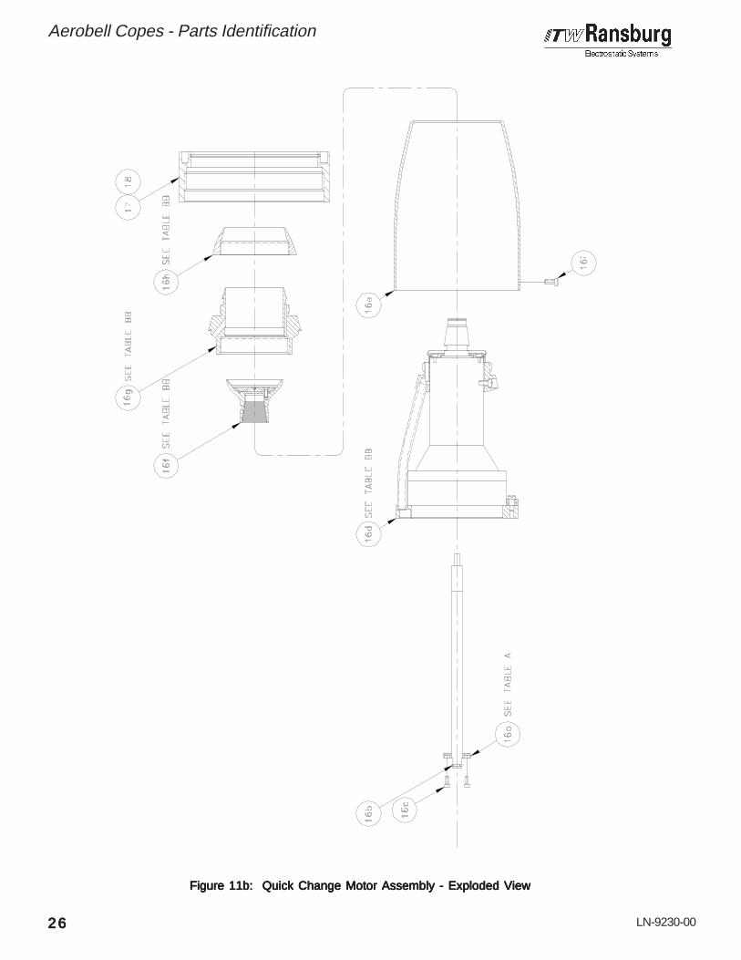
LN-9230-00
Aerobell Copes - Parts Identification
Figure 11b: Quick Change Motor Assembly - Exploded ViewFigure 11b: Quick Change Motor Assembly - Exploded ViewFigure 11b: Quick Change Motor Assembly - Exploded ViewFigure 11b: Quick Change Motor Assembly - Exploded ViewFigure 11b: Quick Change Motor Assembly - Exploded View
2626262626

LN-9230-00
Aerobell Copes - Parts Identification
2727272727
TTTT TA
BL
E
"A"
AB
LE
"A
"A
BL
E
"A"
AB
LE
"A
"A
BL
E
"A"
1 2 3
RP
M-4
41
RP
M-4
40
RP
M-4
39
Da
shD
ash
Da
shD
ash
Da
shN
o.
No
.N
o.
No
.N
o.
ZZZZ ZD
esc
rip
tio
nD
esc
rip
tio
nD
esc
rip
tio
nD
esc
rip
tio
nD
esc
rip
tio
n
Tub
e, F
luid
Fee
d, 1
/16
I.D.
Tub
e, F
luid
Fee
d, 3
/32
I.D.
Tub
e, F
luid
Fee
d, 1
/8 I.
D.
16
aZ
Tub
e, F
eed,
Flu
id1
16
bS
SG
-812
8 (*
)O
-Rin
g, K
alre
z, .2
39 I.
D. x
.379
O.D
.1
16c
SS
F-3
137
Scr
ew, S
oc. H
d. C
ap, M
3 x
.5-6
g x
8mm
Lon
g4
16
dY
Mot
or A
ssem
bly,
Tur
bine
11
6e
RP
M-3
(*)
Shr
oud
116
fX
Bel
l Cup
Ass
embl
y, A
tom
izer
11
6g
WR
ing,
Sha
ping
Air
11
6h
VC
ap,
Sha
ping
Air
11
6i
7674
8-12
F (
*)S
crew
, Fill
iste
r H
d., #
10-3
2 U
NF
x
3/8
Long
3
Item
#Ite
m #
Item
#Ite
m #
Item
#
QU
ICK
QU
ICK
QU
ICK
QU
ICK
QU
ICK
CH
AN
GE
MO
T C
HA
NG
E M
OT
CH
AN
GE
MO
T C
HA
NG
E M
OT
CH
AN
GE
MO
TO
R A
SS
EM
BL
OR
AS
SE
MB
LO
R A
SS
EM
BL
OR
AS
SE
MB
LO
R A
SS
EM
BL YYYY Y
PPPP PA
RA
RA
RA
RA
RT
S L
IST
TS
LIS
TT
S L
IST
TS
LIS
TT
S L
IST
(F
igur
e 1
(F
igur
e 1
(F
igur
e 1
(F
igur
e 1
(F
igur
e 1 1
b)1b
)1b
)1b
)1b
)
Par
t #
Par
t #
Par
t #
Par
t #
Par
t #
Qty
Qty
Qty
Qty
Qty
De
scri
pti
on
De
scri
pti
on
De
scri
pti
on
De
scri
pti
on
De
scri
pti
on
*P
arts
sho
wn
shou
ld b
e ke
pt o
n ha
nd a
s sp
are
part
s fo
r se
rvic
e co
nven
ienc
e.A
ER
OB
ELL
MO
DE
L ID
EN
TIF
ICA
TIO
NA
ER
OB
ELL
MO
DE
L ID
EN
TIF
ICA
TIO
NA
ER
OB
ELL
MO
DE
L ID
EN
TIF
ICA
TIO
NA
ER
OB
ELL
MO
DE
L ID
EN
TIF
ICA
TIO
NA
ER
OB
ELL
MO
DE
L ID
EN
TIF
ICA
TIO
N
Thr
ee d
igits
, as
indi
cate
d by
the
tabl
es, A
thro
ugh
BB
mus
t fol
low
the
basi
c pa
rt n
umbe
r 767
46.
The
firs
t dig
it in
dica
tes
fluid
tube
type
as
show
n in
Tab
le "
A".
The
sec
ond
two
digi
ts in
dica
te b
ell
cup
type
as
show
n in
Tab
le "
BB
".
Exa
mpl
e:
7
6746
X
XX
Bas
ic P
art
Num
ber
T
able
BB
Bel
l Cup
Typ
e
Tab
le A
Flu
id T
ube
Typ
e
02
03
Da
shD
ash
Da
shD
ash
Da
shN
o.
No
.N
o.
No
.N
o.
TTTT TA
BL
E
"BB
"A
BL
E
"BB
"A
BL
E
"BB
"A
BL
E
"BB
"A
BL
E
"BB
"
7674
7-01
7674
7-02
YYYY YD
esc
rip
tio
nD
esc
rip
tio
nD
esc
rip
tio
nD
esc
rip
tio
nD
esc
rip
tio
n
Turb
ine
Ass
y., 3
0 &
57m
m
Turb
ine
Ass
y., 7
0mm
RP
M-4
57
LRP
M40
01-0
0
XXXX XD
esc
rip
tio
nD
esc
rip
tio
nD
esc
rip
tio
nD
esc
rip
tio
nD
esc
rip
tio
n
Bel
l Cup
Ass
y., 5
7mm
Bel
l Cup
Ass
y., 7
0mm
7675
6-00
7663
1-00
WWWW WD
esc
rip
tio
nD
esc
rip
tio
nD
esc
rip
tio
nD
esc
rip
tio
nD
esc
rip
tio
n
Rin
g, S
hapi
ng A
ir, 5
7mm
Rin
g, S
hapi
ng A
ir, 7
0mm
7675
7-00
7663
2-00
VVVV VD
esc
rip
tio
nD
esc
rip
tio
nD
esc
rip
tio
nD
esc
rip
tio
nD
esc
rip
tio
n
Cap
, Sha
ping
Air,
57m
m
Cap
, Sha
ping
Air,
70m
m

LN-9230-00
Aerobell Copes - Parts Identification
2828282828
Figure 12: Turbine Motor Assembly (See Figure 11B / Item 16d)Figure 12: Turbine Motor Assembly (See Figure 11B / Item 16d)Figure 12: Turbine Motor Assembly (See Figure 11B / Item 16d)Figure 12: Turbine Motor Assembly (See Figure 11B / Item 16d)Figure 12: Turbine Motor Assembly (See Figure 11B / Item 16d)
7675
1-00
7675
2-00
7674
7-01
7674
7-02
Pa
rtP
art
Pa
rtP
art
Pa
rtN
o.
No
.N
o.
No
.N
o.
De
scri
pti
on
De
scri
pti
on
De
scri
pti
on
De
scri
pti
on
De
scri
pti
on
57m
m S
hapi
ng A
ir R
ing
70m
m S
hapi
ng A
ir R
ing
DDDD D

LN-9230-00
Aerobell Copes - Parts Identification
2929292929
1 76749-00 Ring, Mounting, Plastic, High Flow 1 2 SSF-3130 Screw, Socket Head Cap, 1/4-20 UNC x 5/8 Long 3 3 76753-08C Screw, Set, Cup Pt. #8-32 UNC x 1/4 Long 1 4 55994-25 Tubing, Teflon, 3/8 O.D. x 1/4 I.D. 5" 5 RPM-401-1 Turbine, Air Bearing, Tested 1 5a RPM-100 (**) Cover, Front, Turbine Assembly (Included in RPM-401-1) 1 5b (***) Screw, Socket Head Cap, M3 x .5 Pitch x 6 Long
(Included in RPM-401-1) Ref 6 SSG-8166 Ring, Glyd 1 7 ------------------------------- -------------------------------------------------------------------------------- --- 8 RPM-2 (*) Retainer, Shaping Air Cap 1 9 76310-00 (*) Muffler, Porous Plastic 110 76750-08C Screw, Shoulder, #8-32, G-10 Fiberglass 511 D (See Chart Page 28) Manifold, Shaping Air, Plastic, High Flow 112 76748-12F Screw, Fillister Head, #10-32 UNF x 3/8 Long 3
Item #Item #Item #Item #Item #
TURBINE MOTTURBINE MOTTURBINE MOTTURBINE MOTTURBINE MOTOR ASSEMBLOR ASSEMBLOR ASSEMBLOR ASSEMBLOR ASSEMBLYYYYY - P - P - P - P - PARARARARARTS LISTTS LISTTS LISTTS LISTTS LIST (Figure 12) (Figure 12) (Figure 12) (Figure 12) (Figure 12)
Part #Part #Part #Part #Part # DescriptionDescriptionDescriptionDescriptionDescription QtyQtyQtyQtyQty
* Parts shown should be kept on hand asspare parts for service convenience.
** The parts shown are included with the sub-assembly or may be ordered separately asspare parts for service convenience.
*** The parts shown are included with the sub-assembly and are only available by ordering(Qty-1) KK-4463, turbine screw kit, as spareparts for service convenience.

LN-9230-00
Figure 13: Turbine Motor Assembly (See Figure 11B / Item 16d)Figure 13: Turbine Motor Assembly (See Figure 11B / Item 16d)Figure 13: Turbine Motor Assembly (See Figure 11B / Item 16d)Figure 13: Turbine Motor Assembly (See Figure 11B / Item 16d)Figure 13: Turbine Motor Assembly (See Figure 11B / Item 16d)
7675
1-00
7675
2-00
7674
7-01
7674
7-02
Pa
rtP
art
Pa
rtP
art
Pa
rtN
o.
No
.N
o.
No
.N
o.
De
scri
pti
on
De
scri
pti
on
De
scri
pti
on
De
scri
pti
on
De
scri
pti
on
57m
m S
hapi
ng A
ir R
ing
70m
m S
hapi
ng A
ir R
ing
DDDD D
Aerobell Copes - Parts Identification
3030303030

LN-9230-00
Aerobell Copes - Parts Identification
3131313131
1 76749-00 Ring, Mounting, Plastic, High Flow 1 2 SSF-3130 Screw, Socket Head Cap, 1/4-20 UNC x 5/8 Long 3 3 76753-08C Screw, Set, Cup Pt. #8-32 UNC x 1/4 Long 1 4 55994-25 Tubing, Teflon, 3/8 O.D. x 1/4 I.D. 5" 5 RPM-401-1 Turbine, Air Bearing, Tested 1 5a RPM-100 (**) Cover, Front, Turbine Assembly (Included in RPM-401-1) 1 5b (***) Screw, Socket Head Cap, M3 x .5 Pitch x 6 Long
(Included in RPM-401-1) Ref 6 7554-105 (*) O-Ring, Viton, 2-034 1 7 LRPM0112-01 Adapter, Seal, Shaping Air Ring, 70mm 1 8 LRPM0111-00 (*) Seal, Shaping Air Ring, 70mm 1 9 76310-00 (*) Muffler, Porous Plastic 110 76750-08C Screw, Shoulder, #8-32, G-10 Fiberglass 511 D (See Chart Page 30) Manifold, Shaping Air, Plastic, High Flow 112 76748-12F Screw, Fillister Head, #10-32 UNF x 3/8 Long 3
Item #Item #Item #Item #Item #
TURBINE MOTTURBINE MOTTURBINE MOTTURBINE MOTTURBINE MOTOR ASSEMBLOR ASSEMBLOR ASSEMBLOR ASSEMBLOR ASSEMBLYYYYY - P - P - P - P - PARARARARARTS LISTTS LISTTS LISTTS LISTTS LIST (Figure 13) (Figure 13) (Figure 13) (Figure 13) (Figure 13)
Part #Part #Part #Part #Part # DescriptionDescriptionDescriptionDescriptionDescription QtyQtyQtyQtyQty
* Parts shown should be kept on hand asspare parts for service convenience.
** The parts shown are included with the sub-assembly or may be ordered separately asspare parts for service convenience.
*** The parts shown are included with the sub-assembly and are only available by ordering(Qty-1) KK-4463, turbine screw kit, as spareparts for service convenience.

LN-9230-00
Aerobell Copes - Warranty Policies
WWWWWARRANTYARRANTYARRANTYARRANTYARRANTY POLICIES POLICIES POLICIES POLICIES POLICIES
WWWWWARRANTYARRANTYARRANTYARRANTYARRANTY FOR FOR FOR FOR FORAEROBELL COPESAEROBELL COPESAEROBELL COPESAEROBELL COPESAEROBELL COPESROTROTROTROTROTARARARARARYYYYY A A A A ATTTTTOMIZEROMIZEROMIZEROMIZEROMIZERThe ITW Ransburg Aerobell Copes rotary atom-izer is warranted to be free of defects in work-manship and material. The terms of this war-ranty, except as hereinafter provided, extendfrom one year from the date of first installation.This excludes equipment failures which are theresult of misapplication, misuse, incorrect main-tenance, or normal wear. If, after inspection byITW Ransburg a defect is confirmed, we will atour option repair, replace or issue credit, minusallowance for usage received.
This WThis WThis WThis WThis Warranty Does arranty Does arranty Does arranty Does arranty Does NOTNOTNOTNOTNOT Cover: Cover: Cover: Cover: Cover:
1. Aerobell Copes that has become inop-erative because of:
a). Misuse - Particularly the flooding ofthe rotor area due to turning on thefluid before the turbine is up tospeed.
SPECIFIC AEROBELLSPECIFIC AEROBELLSPECIFIC AEROBELLSPECIFIC AEROBELLSPECIFIC AEROBELLCOPES AIR TURBINECOPES AIR TURBINECOPES AIR TURBINECOPES AIR TURBINECOPES AIR TURBINEWWWWWARRANTYARRANTYARRANTYARRANTYARRANTYThe air turbine only is warranted for 15,000 op-erating hours, or three years from the date offirst installation, which ever occurs first. If, afterinspection by ITW Ransburg, defect is con-firmed, we will repair or replace the air turbine,free of charge, during the warranty period. Therepaired air turbine (or replacement air turbine)will continue to be warranted for the remainderof the initial warranty period (from installationdate). The warranty period for the air turbinedoes not begin again when a repair is completedunder warranty. Air turbines repaired by ITWRansburg after the warranty period will be war-ranted for 90 days from the date of shipmentfrom the repair center.
b). Negligence.
c). Accidents - Collisions with externalobjects, fires, or similar occurrenc-es.
d). Improper maintenance procedures.
e). Attempted customer repair of airturbine during warranty.
f). Failure to insure clean air to airbearing and turbine.
g). Operating turbine without air bearingair.
h). Operating turbine with less than theminimum specified air bearingpressure (60 psi min., measured atturbine inlet).
i). Operating with imbalanced loads(heavy paint buildup on atomizerbellor shaft, or damaged atomizer bell).
j). Acts of God, flood, earthquake, orsimilar occurrence.
k). Aerobell Copes being operated bycontrol systems not designed byITW Ransburg, or when othershave modified the ITW Ransburgcontrol system, unless reviewedand approved in writing by anauthorized ITW Ransburg TechnicalRepresentative.
2. Labor or incidental costs occasioned byremoval, replacement or repair of rotaryatomizer or air turbine by an unautho-rized entity.
3. Rotary atomizers inspected and deter-mined by ITW Ransburg not to havebeen installed and maintained in accor-dance with ITW Ransburg serviceinstruction LN-9230-00 (latest edition).
3232323232

LN-9230-00
There is no other express warranty, impliedThere is no other express warranty, impliedThere is no other express warranty, impliedThere is no other express warranty, impliedThere is no other express warranty, impliedwarranties, including those of merchantabil-warranties, including those of merchantabil-warranties, including those of merchantabil-warranties, including those of merchantabil-warranties, including those of merchantabil-ity and fitness for a particular purpose areity and fitness for a particular purpose areity and fitness for a particular purpose areity and fitness for a particular purpose areity and fitness for a particular purpose arelimited to one year from purchase and to thelimited to one year from purchase and to thelimited to one year from purchase and to thelimited to one year from purchase and to thelimited to one year from purchase and to theextent permitted by law any and all impliedextent permitted by law any and all impliedextent permitted by law any and all impliedextent permitted by law any and all impliedextent permitted by law any and all impliedwarranties are excluded. This is the exclu-warranties are excluded. This is the exclu-warranties are excluded. This is the exclu-warranties are excluded. This is the exclu-warranties are excluded. This is the exclu-sive remedy, and liability for consequentialsive remedy, and liability for consequentialsive remedy, and liability for consequentialsive remedy, and liability for consequentialsive remedy, and liability for consequentialor incidental damages under any and allor incidental damages under any and allor incidental damages under any and allor incidental damages under any and allor incidental damages under any and allwarranties are exluded to the extent exclu-warranties are exluded to the extent exclu-warranties are exluded to the extent exclu-warranties are exluded to the extent exclu-warranties are exluded to the extent exclu-sion is permitted by law. Some states dosion is permitted by law. Some states dosion is permitted by law. Some states dosion is permitted by law. Some states dosion is permitted by law. Some states donot allow limitations on how long an impliednot allow limitations on how long an impliednot allow limitations on how long an impliednot allow limitations on how long an impliednot allow limitations on how long an impliedwarranty lasts, or the limitation or exclusionwarranty lasts, or the limitation or exclusionwarranty lasts, or the limitation or exclusionwarranty lasts, or the limitation or exclusionwarranty lasts, or the limitation or exclusionof consequential or incidental damages, soof consequential or incidental damages, soof consequential or incidental damages, soof consequential or incidental damages, soof consequential or incidental damages, sothe above limitation or exclusion may notthe above limitation or exclusion may notthe above limitation or exclusion may notthe above limitation or exclusion may notthe above limitation or exclusion may notapply to you.apply to you.apply to you.apply to you.apply to you.
This warranty gives you specific legal rights,and you may also have other rights which varyfrom state to state.
In the event of malfunction, first ensure that theequipment is the correct equipment to do the jobrequired, is properly installed and adjusted, andis correctly maintained and operated. Then, if aclaim is made that ITW Ransburg equipment ora part thereof does not operate properly, contactyour ITW Ransburg distributor through whichthe equipment was purchased or your ITWRansburg representative.
Aerobell Copes - Warranty Policies
NOTES:NOTES:NOTES:NOTES:NOTES:
3333333333
4. Cost of repair/replacement and returntransportation from ITW Ransburg ofmerchandise determined not to bedefective.

LN-9230-00
NOTES:NOTES:NOTES:NOTES:NOTES:

LN-9230-00
NOTES:NOTES:NOTES:NOTES:NOTES:

Form No. LN-9230-00Litho in U.S.A.06/99-1C
© 2004 Illinois Tool Works Inc. All rights reserved.Models and specifications subject to change without notice.
ManufacturingManufacturingManufacturingManufacturingManufacturing1910 North Wayne StreetAngola, Indiana 46703-9100Telephone: 260/665-8800Fax: 260/665-8516
TTTTTechnical/Service Assistanceechnical/Service Assistanceechnical/Service Assistanceechnical/Service Assistanceechnical/Service AssistanceAutomotive Assembly and Tier I Telephone: 800/ 626-3565 Fax: 419/ 470-2040Industrial Systems Telephone: 800/ 233-3366 Fax: 419/ 470-2071Ransburg Guns Telephone: 800/ 233-3366 Fax: 419/ 470-2071
TTTTTechnical Support Representative will direct you to the appropriate telephoneechnical Support Representative will direct you to the appropriate telephoneechnical Support Representative will direct you to the appropriate telephoneechnical Support Representative will direct you to the appropriate telephoneechnical Support Representative will direct you to the appropriate telephonenumber for ordering Spare Parts.number for ordering Spare Parts.number for ordering Spare Parts.number for ordering Spare Parts.number for ordering Spare Parts.