Aero-Structural Blade Design of a High-Power Wind Turbine
10
Aero-Structural Blade Design of a High-Power Wind Turbine 1 Aero-Structural Blade Design of a High-Power Wind Turbine Bruno Miguel Tojo Instituto Superior T´ ecnico, Technical University of Lisbon, Portugal. [email protected] Abstract The present work focused on the development of an aero-structural design framework for a high-power horizontal axis wind turbine. To achieve this, it was necessary to carefully characterize the blade, to develop a suitable fluid-structure interaction solver and, finally, to combine both with post-processing tools. The blade parameterization was inspired in the disc actuator concept, which was then improved through computational fluid dynamics simulations and, the structure was modeled as main spar that has the shape of the blade. It was developed a fluid-structure interaction solver for OpenFOAM, dedicated to simulate wind turbine rotors. The fluid-structure coupling was achieved through a loose coupling strategy, which means that there are separated solvers for the flow and structure analysis, which are combined through the update of boundary conditions. To simulate the blades rotation movement, it was used an approach based on the single rotating frame method, meaning that the whole domain rotated with the turbine rotor with a constant angular velocity. For the structural domain, a linear elastic solver was used, able to model the small deformations due to the distributed aerodynamic forces. The simulations of the rotor produced valid and interesting results namely, correct flow fields and pressure distributions. Considering that it is expected horizontal axis wind turbine rotors to continue growing to even larger sizes than the one modeled, it was shown that blade displacements due to flow induced forces are definitely a problem that needs to be taken into account when designing new wind turbine blades. Although it was not possible to analyze the consequences of these effects in the turbine output power, a post-processing method to make this evaluation was presented. To obtain relevant results on this subject, it would be important to further develop the structural solver and model, giving them the correct proprieties to model wind turbine blades. Keywords: Wind Turbine, Fluid-Structure Interaction, CFD Development, High-Fidelity Analysis, Single Rotating Frame, OpenFOAM, ICEM- CFD. 1 INTRODUCTION Following the recent advances made in terms of wind energy generation, and considering that next step for this industry is to invest in offshore developments, it is important to research in this area, finding ways to produce better wind turbines. The work presented consists on the development of an aero- structural design framework for a high-power horizontal axis wind turbines. To achieve this, it was important to review of the state the art of scientific research in aerodynamic, structural and coupled models for wind turbine blades. 1.1 Aerodynamics and Computational Fluid Dy- namics (CFD) CFD studies are always a clever way to introduce, test and design new blade models. Disgraskar [1] presented a project that is somewhat similar to the one presented in the current work, as the objective was also to simulate the flow around a wind turbine, using OpenFOAM [2]. For this, special bound- ary conditions were developed, such as cyclic grid interfaces, and a multi reference frame solver, to model the wind turbine as accurate as possible. It was possible to model the NREL Phase IV and DU wind turbines, being the former modeled quite successfully, and even the wake was calculated with suc- cess, but it was not possible to get good results for the later. Also using the NREL turbine, in [3] it is presented a com- parative study between the theory of the actuator disc, the re- sults of a CFD analysis on a high resolution structured mesh, with advanced turbulence and transition models, and experi- mental results, discussing the possibility of creating a hybrid code. It was concluded that the CFD simulation provided an excellent match with experimental data in the attached flow regime. However, the CFD and panel code over-predict peak lift and tend to underestimate stalled flow. The results pre- sented support the use of a calibrated actuator disk methodol- ogy based on a normal fidelity CFD modeling approach. Im- plementing actuator momentum correlations obtained from an equivalent CFD analysis offers a potentially economical methodology for simulating complete multiple wind turbines within a specific environment. Another CFD study of the NREL PHASE IV wind tur- bine is presented by Sezer-Uzol [4] using a solver that uses a finite volume formulation of the Navier-Stokes equation for 3D, compressible, unsteady or steady-state. Three conditions were studied in which the inviscid results show that the flow is attached for the low velocity cases, with the case where yaw angle is not zero having an asymmetric wake structure, whereas there is a massive separation over the entire blade span in the post-stall case. Although on a much smaller scale, the mesh presented in this work served as inspiration for the mesh presented in the current report, as the outer mesh is represented by a cylinder and the region of the blades has a much smaller elements then the outside mesh, size restriction had to be applied as the computations presented in [4] were made using NREL and NASA clusters. The project presented by Nilsson [5] proposed to study Bruno Tojo July 2012
Transcript of Aero-Structural Blade Design of a High-Power Wind Turbine

Aero-Structural Blade Design of a High-Power Wind Turbine 1
Aero-Structural Blade Design of a High-Power Wind Turbine
Bruno Miguel Tojo
Instituto Superior Tecnico, Technical University of Lisbon, [email protected]
Abstract
The present work focused on the development of an aero-structural design framework for a high-power horizontal axis windturbine. To achieve this, it was necessary to carefully characterize the blade, to develop a suitable fluid-structure interactionsolver and, finally, to combine both with post-processing tools.
The blade parameterization was inspired in the disc actuator concept, which was then improved through computationalfluid dynamics simulations and, the structure was modeled as main spar that has the shape of the blade. It was developeda fluid-structure interaction solver for OpenFOAM, dedicated to simulate wind turbine rotors. The fluid-structure couplingwas achieved through a loose coupling strategy, which means that there are separated solvers for the flow and structureanalysis, which are combined through the update of boundary conditions. To simulate the blades rotation movement, itwas used an approach based on the single rotating frame method, meaning that the whole domain rotated with the turbinerotor with a constant angular velocity. For the structural domain, a linear elastic solver was used, able to model the smalldeformations due to the distributed aerodynamic forces.
The simulations of the rotor produced valid and interesting results namely, correct flow fields and pressure distributions.Considering that it is expected horizontal axis wind turbine rotors to continue growing to even larger sizes than the onemodeled, it was shown that blade displacements due to flow induced forces are definitely a problem that needs to be takeninto account when designing new wind turbine blades.
Although it was not possible to analyze the consequences of these effects in the turbine output power, a post-processingmethod to make this evaluation was presented. To obtain relevant results on this subject, it would be important to furtherdevelop the structural solver and model, giving them the correct proprieties to model wind turbine blades.
Keywords: Wind Turbine, Fluid-Structure Interaction, CFD Development, High-Fidelity Analysis, Single Rotating Frame, OpenFOAM, ICEM-CFD.
1 INTRODUCTION
Following the recent advances made in terms of wind energygeneration, and considering that next step for this industry isto invest in offshore developments, it is important to researchin this area, finding ways to produce better wind turbines.The work presented consists on the development of an aero-structural design framework for a high-power horizontal axiswind turbines.
To achieve this, it was important to review of the statethe art of scientific research in aerodynamic, structural andcoupled models for wind turbine blades.
1.1 Aerodynamics and Computational Fluid Dy-namics (CFD)
CFD studies are always a clever way to introduce, test anddesign new blade models. Disgraskar [1] presented a projectthat is somewhat similar to the one presented in the currentwork, as the objective was also to simulate the flow around awind turbine, using OpenFOAM [2]. For this, special bound-ary conditions were developed, such as cyclic grid interfaces,and a multi reference frame solver, to model the wind turbineas accurate as possible. It was possible to model the NRELPhase IV and DU wind turbines, being the former modeledquite successfully, and even the wake was calculated with suc-cess, but it was not possible to get good results for the later.
Also using the NREL turbine, in [3] it is presented a com-parative study between the theory of the actuator disc, the re-sults of a CFD analysis on a high resolution structured mesh,
with advanced turbulence and transition models, and experi-mental results, discussing the possibility of creating a hybridcode. It was concluded that the CFD simulation provided anexcellent match with experimental data in the attached flowregime. However, the CFD and panel code over-predict peaklift and tend to underestimate stalled flow. The results pre-sented support the use of a calibrated actuator disk methodol-ogy based on a normal fidelity CFD modeling approach. Im-plementing actuator momentum correlations obtained froman equivalent CFD analysis offers a potentially economicalmethodology for simulating complete multiple wind turbineswithin a specific environment.
Another CFD study of the NREL PHASE IV wind tur-bine is presented by Sezer-Uzol [4] using a solver that usesa finite volume formulation of the Navier-Stokes equation for3D, compressible, unsteady or steady-state. Three conditionswere studied in which the inviscid results show that the flowis attached for the low velocity cases, with the case whereyaw angle is not zero having an asymmetric wake structure,whereas there is a massive separation over the entire bladespan in the post-stall case. Although on a much smaller scale,the mesh presented in this work served as inspiration for themesh presented in the current report, as the outer mesh isrepresented by a cylinder and the region of the blades has amuch smaller elements then the outside mesh, size restrictionhad to be applied as the computations presented in [4] weremade using NREL and NASA clusters.
The project presented by Nilsson [5] proposed to study
Bruno Tojo July 2012

Aero-Structural Blade Design of a High-Power Wind Turbine 2
OpenFOAM as a tool for turbulent flow in water turbines.The aim was to validate OpenFOAM performance againstboth commercial CFD codes and experimental data. In thatpaper they show that the results obtained were as efficient asthe ones achieved using the commercial codes, fitting equallywell to the experimental data. Based on this, OpenFOAMcan confidently be used as a CFD tool to analyze and designturbines.
1.2 Structural Models and Finite Element Method(FEM)
As part of the design process, a wind turbine must be ana-lyzed for the aerodynamic, gravitational, inertial and oper-ational loads that will experience during its design life. Al-though structural analysis has always been important in thewind turbine blade design, mainly because of fatigue prob-lems, as the size of blade become bigger, so do the concernswith blade structural design [6, 7].
Jensen et al. [8] described the structural testing and numer-ical simulation of a 34 m composite HAWT blade with a loadcarrying main spar. Their work starts with the same premisethat the current project starts, that is the fact that HAWTare becoming bigger with a considerable increase in rotorsize, which means that structural problems on the bladesneed to be addressed. The finite element method (FEM) hasbeen used traditionally to investigate global behavior in termsof, for example, eigen frequencies, tip deflections and globalstress and strain levels. In their work, the FE model wascalibrated with data from a full scale model, which meansits accurate and it was possible to evaluate complex loads,modeling actual wind conditions, otherwise impossible on thephysical model.
The design of a wind turbine structure involves many con-siderations such as strength, stability, cost and vibration. In[9], an optimization model for the design of a typical bladestructure of HAWT is presented and it is focused on the re-duction of vibrations. A good design philosophy for reducingvibration is to separate the natural frequencies of the struc-ture from the harmonics of rotor speed. The main spar wasrepresented by thin-walled tubular beam composed of uniformsegments, each of which had different cross-subsectional prop-erties and length. The optimization variables were chosen tobe the cross-subsectional area, radius of gyration and lengthof each segment. The optimal design is pursued with respectto maximum frequency design criterion. The problem wasformulated as a non-linear mathematical programming prob-lem solved by multi-dimensional search techniques. Struc-tural analysis was restricted to the case of uncoupled flap-ping motion of the rotating blade, where an exact method ofsolution was given for calculating the natural vibration char-acteristics. The results presented showed that the approachused was efficient and improved the reference design.
Bechly [10] described the optimization on the structure of aHAWT blade. A computational code was developed to makea detailed finite element mesh from data obtain from bladeelement theory and panel code predictions. This preliminary
blade design was done using NACA 4412 airfoils and varyingtwist and chord, similar to the method that will be explainedfurther in this document. The blade was then constructedfrom fiberglass skin and additional stiffening was added at thehub connection. A detailed finite element mesh of the bladewas then built using a propose written program. The finiteelement results, obtained using a commercial FEM software,compared well with static bending and twisting deflections ofthe blade and, according to the dynamic analysis, it was evenpossible to understand that the natural frequencies of therotating blade are higher than non-rotating, due to stress-stiffening.
1.3 Fluid-Structure Interaction
Following the concerns explored in the previous subsections,fluid structure interactions(FSI) are currently becoming morerelevant in the design of new HAWT. This phenomenon is con-nected to the deflection of elastic materials when subjectedto flow induced loads, as well as the alterations that this de-flection produce on the flow, changing its characteristics.
The FSI computations are usually classified in weakly orstrongly coupled. For weakly coupled systems, it is commonto use partitioned solvers, in which the main problem is howto pass the information between the solvers. On the otherhand, for strongly coupled ones, the only choice is to use asingle solver that solves both fluid and structural problems,but which is much more complex than the partitioned one[11].
Aerostructural analysis techniques are a specialization ofmore general FSI solution methods, where the fluid in ques-tion is air, and the structure represents a flexible componentsuch as an aircraft wing or wind turbine blade. Aerostruc-tural design optimization using high-fidelity models is acomputationally intensive multidisciplinary design optimiza-tion (MDO) problem, usually using high-fidelity aerodynamicanalysis in the aerostructural problem while using consider-ably smaller finite-element models. This is often justifiedsince the primary area of interest in these studies is the aero-dynamic performance of the aerostructural system.
Kennedy et al. [12] presented both aerostructural analysisand design sensitivity methods that are designed to be effi-cient when the aerodynamic and structural disciplines bothrequire significant computational resources and time. Theaerodynamic analysis uses a parallel panel code, coupled toa parallel finite-element code for the analysis of compositestructures. This finite-element code is specifically designed,including geometric nonlinearity and has analytic design vari-able sensitivity analysis capability. The inter-disciplinarycoupling is handled by passing pressure and displacement val-ues through a parametric surface representation of the outermold line of an aircraft.
Aerodynamic and structural optimization of HAWT bladeshas become a subject of considerable interest, as the ultimategoal is to reduce the cost of energy production. This designprocess is a multidisciplinary task, involving conflicting re-quirements, such as maximum performance with minimum
Bruno Tojo July 2012

Aero-Structural Blade Design of a High-Power Wind Turbine 3
loads and noise. Moreover, since the turbine operates in awide range of wind conditions, it can only be optimized forone. In [13], the optimization was achieved by modifying thetwist and chord of the blade, as well as the airfoils. A mini-mum cost of energy was obtained, which is lower then currentcommercial turbines, but it was also concluded that, with theuse of traditional airfoils, it is impossible to reduce the costof energy from the one that is already achieved.
2 METHODOLOGY FOR WIND TURBINEAERO-STRUCTURAL ANALYSIS
Following the strategy illustrated in Fig.1 and, having decidedthat the toolbox to perform the CFD simulations would beOpenFOAM [2] which, as clarified above, is a good optionfor fluid structure interaction simulations, as well as accu-rate simulations on wind turbines. It was then necessaryto evaluate the other parts of the methodology, such as theparametrization of the blade, mesh and geometry generatorsand finally, post processing of the results once the simulationswere performed.
Blade Parameterization
Post-Processing
Mesh Generation
FlowSolver
FSICoupling
StructuralSolver
Figure 1: Schematic of WT aero-structural blade analysis.
The first important step in a CFD simulation is to decidethe dimensionality of the model to use. The simulation shouldbe as simple as possible in order to obtain good results quickly,but still capture the relevant physical phenomena. 2D sim-ulations are often used in the first steps of design and, formany cases, it produces good preliminary results. A full 3Dsimulation is needed to obtain correct secondary flows. Thisis specially important in compressors and fans (or HAWT),where the negative pressure gradients make boundary layersgrow much quicker than what they do in regular turbines.Having this in mind, it was decided that in a first approach itwould be used a simple 2D mesh of a beam that was expectedto deform the same way a HAWT blade would. This modelwas used to test solvers and validate the fluid-structure inter-action solver that was developed. Afterward a full 3D modelfor the HAWT blades it was created, step by step.
2.1 Blade Parameterization
As a first approach, the surface will be modeled using a dis-cretization presented by Kim et al. [14]. This discretizationstarts with the selection of the airfoils, to which a series ofcoordinate transformations will be applied to obtain a HAWTblade. From the literature reviewed, DU airfoils seemed to bethe obvious choice, unfortunately it was impossible to accessthese airfoils. As such, airfoils from NACA and S8xx series,with similar characteristics [15], which were easier to access.
The power developed by a rotor at a certain wind speeddepends on the relative velocity between the wind and therotor tip. The ratio between these two speeds, called the tipspeed ratio(λ), is defined as
λ =RΩ
U==
2πNrR
60U, (1)
where Ω is the angular velocity, R is the radius of the ro-tor and Nr is the rotational speed of the rotor. The designtip speed ratio is usually defined between 7 and 9 for largewind turbines. As λ gets bigger, the blade will be more slen-der and flexible, which has the advantage of reducing theload. However, it may cause interference problems betweenthe blade and the tower at extreme wind conditions and theblade rotation speed may need to be increased to achieve thetargeted output power. On the contrary, a smaller value willcontribute for the blade being thicker and cause greater axialthrust forces.
The rotor geometry is periodic so it is recomened to usecylindrical coordinates. To define the 3D blade, it is conve-nient to define an adimensional parameter for the directionnormal to the flow direction, used to define how the airfoilwill be altered in a certain position, and defined as
µ =r
R, (2)
where r is the distance do the blade axis of rotation and R isthe radius of the turbine.
As the blade is finite, it was necessary to define a blade tiploss factor,
f =2
πcos−1(e1/((N/2)(1−µ)/µ)
√1+(λdesignµ2)/(1−a)) , (3)
as it was first define by Prandlt and then modified by Glauert[16] in their aproach to the BEM theory. This definition de-pends on the flow induction factor a, which the exact valueis given by
a =1
3+
1
3f − 1
3
√1− f + f2 , (4)
making it necessary to calculate this values using a recursivemethod.
Wind turbine blades are designed with tapered and twistedshapes to obtain maximum power output with high efficiency.In [14] several discretizations for the tapper across the bladewere proposed, having all similar aerodynamic results, from
Bruno Tojo July 2012

Aero-Structural Blade Design of a High-Power Wind Turbine 4
which the best chosen to be applied in this work was
c
R=
2π
N
4λ2µ2a′√(1− a)
2+ (λµ(1 + a′))
2, (5)
where N is the number of blades in the HAWT and Cl is thelift coefficient of the airfoil for the angle of attack α defined.Which depends on another flow induction factor a′
a′ =a(1− a/f)
λ2µ2, (6)
which also takes in account the tip speed ratio and the posi-tion in the blade.
At the locations for which the chord was calculated, it wasalso calculated the blade twist φ , which is defined by
tan(φ) =1− a
λµ(1 + a′), (7)
which is then applied by rotating the airfoil at that positionby a pitch angle θ which also depends on the angle of attackon the blade as is defined by
θ = α− φ . (8)
All these equations were programmed in a python [17] scriptthat accepted regular airfoil files, being possible to define theairfoil in up to five radial subsections of the blade, and wherethe positions that were not defined by the user would be aresult of a interpolation between the coordinates of the twoprescribed airfoils that were closer to that location.
2.2 Mesh Generation
The definition of the mesh is of major importance. A goodmesh should have enough definition to be realistic, but not toomuch so that the the computational time requires is accept-able for a work of this nature. To have an acceptable meshthat produced good results in OpenFOAM, it was necessaryto evaluate the capabilities and possibility of integration withthe solver software of several mesh generators.
After selecting ICEMCFD as the mesh generator, a pythonscript was developed and functions were defined to automati-cally generate the different commands, such as straight lines,splines and surfaces. This script was different for the solidand fluid meshes and the commands generated were thensaved to ICEMCFD replay files. These codes generate thegeometries defined for the fluid and solid domains and de-fine the blocking for each of the geometries. The mesh isthen computed and exported in Fluent format, and is copiedto the case folder and converted to the OpenFOAM formatusing fluent3DMeshToFoam, which is the default mesh con-verter from OpenFOAM to convert thee-dimensional Fluentmeshes. All this process was programed to be automatic.
Using the capabilities of the software used and the codecreated, the point cloud created previously was uploaded, andusing these points the blade starts to be formed by defining
splines across the all points of the blade. The surfaces wereprogramed to be created automatically from these lines, usingas much automation as possible in order to be possible tochange the geometry at any time without having to redefineall the surfaces.
2.3 Post Processing
To evaluate the quality of the design, it was necessary tocalculate the power that could be extracted from the blades.The method achieved consists of using an OpenFOAM librarythat calculates forces and moments on a determined surfacefor each time step, which can be viscous or pressure forces,saving the results to a data file, which means it would giveall the information needed to calculate the mechanical powergenerated by the blades. The information obtained has thento be processed: the correct couples of forces (viscous andpressure based) were added the power obtained from a rotat-ing body was calculated using moment generated by the flowon the blades (Torque - T),
P = T ∗ Ω , (9)
where Ω is the rotation speed in rad/s. In addition, thedrag/trust forces were also calculated, which are importantas the structural elements in the HAWT must be able to sup-port it, and the power coefficient (CP ) which served as acomparison between the results obtained, and the maximumtheoretical possible and the values which are reachable withtodays top commercial solutions. To present the results asclear as possible, it was created a small code which make thecalculations and generate the plots of the parameters calcu-lated throughout the simulations.
3 FSI SOLVER DEFINITION
3.1 icoFsiFoam
icoFsiFoam is the fluid-structure interaction (FSI) solveravailable in the standard distribution of OpenFOAM [18].This solver is useful for weakly coupled systems with smallstructural deformations and laminar fluid flow. The struc-tural part is based on stressedFoam, thus limited to linearstress strain relationships and small deformations. The fluidpart of the solver is based on the icoFoam and is limited toNewtonian fluids in incompressible, laminar flow.
This solver consists, in fact, in having multiple solvers side-by-side, which means that each solver uses its own mesh, withaccess to its fields, material properties, solver controls, etc.The fluid-Structure coupling is achieved through boundarycondition updates. In this case, this coupling is achieved bythe following loop: the pressure data from fluid is moved tostructure; the structural equations are solved; the displace-ment of the solid mesh is then transfered to fluid mesh; thefluid flow is solved with mesh motion and the loop restarts.
To test this solver, it was used a flow around a 2D struc-tured mesh, and its structural counterpart. The flow has anuniform velocity inlet at 4m/s and, the results are presentedin Fig.3 and Fig.4 for comparison with the developed solver.
Bruno Tojo July 2012

Aero-Structural Blade Design of a High-Power Wind Turbine 5
3.2 simpleFsiFoam
Due to the major limitations of icoFsiFoam, as the impossi-bility to define a turbulent flow, it was necessary to develop asolver that could model the flow around a turbine blade moreaccurately. This was considered important due to the factthat the flow over wind turbine blade is always turbulent. Iswas decided to develop simpleFsiFoam, a FSI solver based onsimpleFoam. This solver takes advantage of the simplicity ofsimpleFoam, as well as the extra functionalities that it hasover icoFoam.
As simplicity and flexibility were important, the fluid-structure coupling was achieved in the same way that is donein icoFsiFoam, which means that there is still two differentmeshes, one for the fluid and the other for the structuralsolver. The meshes do not need to have the same amountof elements in the correspondent boundaries, which is idealfor the coupled optimization process, as small variations canbe accomplished from both meshes, without having problemswith the coupled properties.
As described earlier, the partitioned approach is being im-plemented for this work, employing a staggered solution pro-cedure wherein each domain. This approach was also usedbecause of the compatibility with black-box solvers, whichmeans that even though this solver has been developed touse stressedFoam and simpleFoam, any of the solvers may bereplaced by a similar one, without much change in the code,simply replacing the part were the calculations are made.
Each iteration begins with setting the pressure around thesolid mesh, using the last iteration fluid information. Thesolid part is then solved and the displacement is applied, de-forming both of the meshes, and finally the fluid is solved. Af-ter each iteration, the solver evaluates if it is time to save thesolution, as it is possible to define in controlDict the writinginterval, and increments time, until the end time is reached.
To define a case, it is necessary to define the two casesin the same folder and define symbolic links between them,as is shown in Fig.2. These soft links linking together thesettings for the fluid phase with the solid phase are necessaryin order for the solver to get input to the solution of both thefluid and structural equation systems. The fluid-structureinterface is defined after both the fluid and solid meshes havebeen created.
The basic layout is the same as in any OpenFOAM case,but much more information is required. In the 0 folder forthe fluid is defined the initial and boundary conditions, usingthe U file to define velocity associated to each boundary; thep file to impose the pressure settings; and nuT, nuTilda, k,omega and epsilon are used to define the turbulence proper-ties depending on the turbulence model to use. The file mo-tionU contains the conditions for the deforming mesh motion,which is a requirement for the FSI analysis. Using moving-WallVelocity as the boundary condition in U at the interface,the motion of the mesh at the interface is implemented as aDirichlet boundary condition for the fluid velocity. For thesolid mesh, in 0 the only property that has to be defined is
the initial displacement which is set on the u file.
<case>
fluid
0UpnuTilda
motionUnuT
k, epsilon, omega
constant
polyMesh
pointscellsfacesboundary
couplingPropertiesdynamicMeshDictRASProperties
turbulencePropertiestransportProperties
systemcontrolDictfvSchemesfvSolutiontetFemSolution
solid
0u
constant
polyMesh
pointscellsfacesboundary
mechanicalProperties
system
fvSchemesfvSolution
Figure 2: Schematic of the definition of a case for simpleFsiFoam
In the the constant directories most of the information con-tained is about the meshes and the material properties, as ex-plained previously, the polyMesh folders contain all the nec-essary information about the meshes, as for the fluids trans-port properties, such as density and viscosity, are defined inthe file named transportProperties, while the solids materialproperties like density, Young modulus, possion coefficientetc., are defined in mechanicalProperties. As the names de-note, the turbulence properties and model are defined usingthe RASProperties and turbulenceProperties files. In the con-stant of the fluid part are also defined most of the settingsgoverning the fluid-structure interaction are defined: in cou-plingProperties are defined the coupled boundaries and themoving mesh patch; the settings for the solution of this patchmotion are defined in dynamicMeshDict.
The system directories are where the solution procedure issetup. Settings such as end time, time step and time intervalfor output to be written are all defined in controlDict, also inthis file is defined if some none default library is going to beused, as is the case with the library that calculates the forcesor the special libraries for turbo-machinery applications. Thefiles fvSchemes contain information about which differencingschemes to use and the files fvSolution the settings for con-vergence tolerances.
In the development versions, OpenFOAM has a vertex-based, unstructured mesh motion solver, which is used inthis case. This solver executes Laplace face decompositionand performs very well for many problems and it is easy toimplement because only motion on the tracked interface is re-quired, but it does have limited functionality. In particular,in its current form it does not function properly for parallelsolutions and it does not support periodic (cyclic) bound-aries. This is a major limitation to the use of OpenFOAM
Bruno Tojo July 2012

Aero-Structural Blade Design of a High-Power Wind Turbine 6
as a fluid-structure interaction tool for turbo-machines, asthis machines usually have periodic geometries, which meansthat a big part of the computing power is wasted because ofthe impossibility to use periodic boundaries. Furthermore, inthe special case of the horizontal axis wind turbine where 3Deffects are very important, the analysis would really benefitfrom a finner mesh that could only be feasible with the useof parallelization.
The same case that was tested with icoFsiFoam was testedwith the new solver. The results were similar but, as in thecase where it was used simpleFoam, the decrease in velocitydue to turbulence is evident.
(a) icoFsiFoam
(b) simpleFsiFoam
Figure 3: Velocity arround a 2D beam using FSI solvers.
Comparing the results of the deformation of the beam be-tween the two fluid-structure interaction solvers in Fig.4, it ispossible to observe that the laminar solver produces a largerdeformation of the beam, as the velocity is bigger, so is thepressure differential between the two sides of the blade.
(a) icoFsiFoam (b) simpleFsiFoam
Figure 4: Displacement caused by the flow around a 2D beam
3.3 fsisimpleSRFFoam
After trying to obtain results by applying a series of rotat-ing velocity boundary conditions, using simplefsiFoam, thisrevealed to be impossible. To obtain better results for theHAWT blades simulations, and considering the limitations inthe computing power available, it was necessary to find a so-
lution that brought better results and was computationallycheap.
The solution to this problem was obtained by using a singlerotating frame (SRF) solver, since a rotating frame of refer-ence is often used to model flows in rotating machines. In thissolver the flow is unsteady in an inertial frame because theblades or rotors sweep the domain periodically as shown inFig. 5(a). However, it is possible to perform the calculationsin a domain that moves with the rotating coordinate whichis fixed on the rotating part, and for this the angular velocitymust be set as symmetric to the real velocity (Fig.5(b)). Theflow is steady relative to the rotating frame, which reducesthe computational cost needed for a more accurate analysis.When transposing the results for the inertial referential, itappears as the blades are moving(Fig.5(c)).
This approach is appropriated when the flow at the bound-ary between the rotating parts and the stationary parts isweakly affected by the interaction. It provides a reasonabletime-averaged simulation result for many applications. Ro-tating frames do not physically rotate anything and thereforedo not show transient effects due to the real motion and theCoriolis and centrifugal forces are treated as body forces. Anyproblems where transient effects due to rotor-stator interac-tion are small are candidates to use the rotating frame ofreference approach.
(a) Inertial referential (b) Rotating referen-tial
(c) Equivalent motionof the blades
Figure 5: Single rotating frame of reference. In [19].
Using the same strategy as it was explained in Sec.3.2, itwas developed another FSI solver for OpenFOAM, now usingas base the Single Rotating Frame Solver(simpleSRFFoam).This was the solver used in the final simulations, which pro-duced relatively good results. In the definition of the case,the only differences to the simpleFsiFoam case is that therotational speed must be defined, in the constant folder, ina file called SRFProperties, and the boundary conditions forthe velocity are now defined in the Urel file, where the veloc-ity in the boundaries may be defined as relative or absolute.As stated before, all the calculations are made in the rotatingreferential and, only at the end, properties are transposed tothe inertial referential. In this the absolute velocity is calledUabs.
4 Wind Turbine Definition and Simulations
The final simulation results that were considered importantto reach to the FSI simulation, as well as the results for thissimulation will be presented in this section.
Bruno Tojo July 2012
Aero-Structural Blade Design of a High-Power Wind Turbine 7
4.1 Wind Turbine Flow Simulation
Using simpleSRFFoam was then possible to simulate correctlythe flow around the blades. The mesh used is presented inFig.6, where the angular velocity was set to −15.11rpm andthe inlet axial velocity was set to 12.1m/s. The results forthe velocity vector field (Fig.6(b)), were as expected in a rotorof a wind turbine, and the convergence was achieved quicklyand even the values for mechanic power produced, from thepressure differential between the side of the blades, seemedpromising.
(a) Mesh (b) Velocity vector plot
Figure 6: SRF simulation of the rotor.
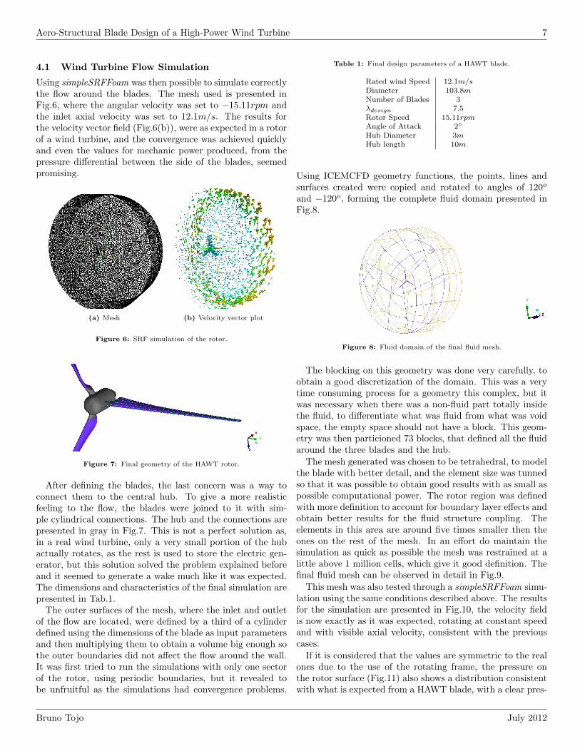
Figure 7: Final geometry of the HAWT rotor.
After defining the blades, the last concern was a way toconnect them to the central hub. To give a more realisticfeeling to the flow, the blades were joined to it with sim-ple cylindrical connections. The hub and the connections arepresented in gray in Fig.7. This is not a perfect solution as,in a real wind turbine, only a very small portion of the hubactually rotates, as the rest is used to store the electric gen-erator, but this solution solved the problem explained beforeand it seemed to generate a wake much like it was expected.The dimensions and characteristics of the final simulation arepresented in Tab.1.
The outer surfaces of the mesh, where the inlet and outletof the flow are located, were defined by a third of a cylinderdefined using the dimensions of the blade as input parametersand then multiplying them to obtain a volume big enough sothe outer boundaries did not affect the flow around the wall.It was first tried to run the simulations with only one sectorof the rotor, using periodic boundaries, but it revealed tobe unfruitful as the simulations had convergence problems.
Table 1: Final design parameters of a HAWT blade.
Rated wind Speed 12.1m/sDiameter 103.8mNumber of Blades 3λdesign 7.5Rotor Speed 15.11rpmAngle of Attack 2
Hub Diameter 3mHub length 10m
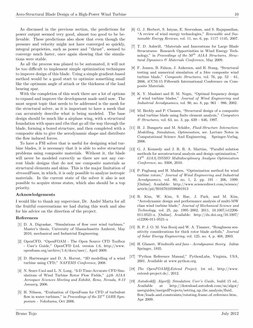
Using ICEMCFD geometry functions, the points, lines andsurfaces created were copied and rotated to angles of 120o
and −120o, forming the complete fluid domain presented inFig.8.
Figure 8: Fluid domain of the final fluid mesh.
The blocking on this geometry was done very carefully, toobtain a good discretization of the domain. This was a verytime consuming process for a geometry this complex, but itwas necessary when there was a non-fluid part totally insidethe fluid, to differentiate what was fluid from what was voidspace, the empty space should not have a block. This geom-etry was then particioned 73 blocks, that defined all the fluidaround the three blades and the hub.
The mesh generated was chosen to be tetrahedral, to modelthe blade with better detail, and the element size was tunnedso that it was possible to obtain good results with as small aspossible computational power. The rotor region was definedwith more definition to account for boundary layer effects andobtain better results for the fluid structure coupling. Theelements in this area are around five times smaller then theones on the rest of the mesh. In an effort do maintain thesimulation as quick as possible the mesh was restrained at alittle above 1 million cells, which give it good definition. Thefinal fluid mesh can be observed in detail in Fig.9.
This mesh was also tested through a simpleSRFFoam simu-lation using the same conditions described above. The resultsfor the simulation are presented in Fig.10, the velocity fieldis now exactly as it was expected, rotating at constant speedand with visible axial velocity, consistent with the previouscases.
If it is considered that the values are symmetric to the realones due to the use of the rotating frame, the pressure onthe rotor surface (Fig.11) also shows a distribution consistentwith what is expected from a HAWT blade, with a clear pres-
Bruno Tojo July 2012

Aero-Structural Blade Design of a High-Power Wind Turbine 8
(a) Overview (b) Longitudinal cut
(c) Rotor Detail
Figure 9: Final fluid mesh details.
sure differential between the two sides, presenting a suctionpeak near the leading edge.
(a) Stream lines for the relative ve-locity
(b) Stream lines for the absolute ve-locity
Figure 10: Final results for the flow simulations.
Figure 11: Pressure on the rotor.
4.2 Wind Turbine Blade Structural Simulation
Although it was one of the main points in the work, it wasnecessary to simplify the structural model due to time re-strictions. It was decided to eliminate the contributions ofthe leading and trailing edge of the blade in order to have amore regular mesh. As it seemed that the problems with theICEMCFD meshes in stressedFoam were related to the un-structured meshes, it was created a structured mesh for thewind turbine blade that could represent this blade accuratelyusing only hexahedral elements.
Figure 12: Blade structural mesh.
The blade is then defined as a solid with hexahedral ele-ments seen in Fig.12, with similar structural characteristics toaluminum. This is a very simplified solution but acceptableas most of the structural loads of the blade are supported bywebs in the center part of the blade [8], as so that this is theinstrumented part on structural testings.
Using this mesh, and applying a pressure of 600Pa in the zdirection at the tip, the results obtain are presented in Fig.13.The displacements results were as expected, almost zero in theother directions and is only a valuable value in the directionwhere the force is applied.
As for the stress, the results obtained were also physicallyconsistent and show that the major concentration is in thethinner portion in the clamped top.
(a) Displacement z (b) Equivalent stress
Figure 13: Simulation of the blade using stressedFoam.
As the results seemed good enough, this was the mesh thatwas used in the following FSI studies.
4.3 FSI Simulation and Results
After all preliminary studies concluded, the results for thefluid-structure interaction in a HAWT are presented in thissubsection. The meshes, materials properties and fluidboundary conditions were the same that were defined in thelast case for each part, with the necessary difference that nowthe blade was left free to deform in both solid and flow meshes.
The results obtained for the deformation are shown inFig.14. This displacements, considering all the simplifica-
Bruno Tojo July 2012

Aero-Structural Blade Design of a High-Power Wind Turbine 9
tions that were made, are impressive. If a solid metal beamdislocates more than 2cm just by the effects of the flow, it ispossible to infer that these displacements, can indeed becomea problem. Furthermore, it is also notable that the majordisplacements happen in the directions normal to the flow.This clearly shows that the solver is being capable of passingthe single rotation frame results to the structural domain.
Figure 14: Displacement in the blades due to the flow.
In the flow domain, the results shown are also interest-ing: as shown in Fig.15, the pressure differential between thesides of the blade is clear, pushing the blade due to aerody-namic forces, producing power as shown next. The velocityprofile also showed physically correct results, the domain isdefinitely moving at constant rotational speed as, it is visiblein Fig.15(b), the velocity increases linearly from the root ofthe blade to achieve the maximum value in the tip.
(a) Pressure
(b) Velocity magnitude (transversalcut)
(c) Velocity magnitude (axial cut)
Figure 15: Flow results on the FSI simulation of the HAWT blades.
Using the script described in Sec.2.3, the values for themechanical power and power coefficient were calculated andpresented in Fig.16. The results are probably a bit over pre-dicted since, as the forces script in OpenFOAM might not bevery accurate. Nevertheless, the turbine in which the param-eterization was based [14] was projected to produce 5MW sothe results obtained are in concordance with this.
Time0.8 1.4 2.01.81.61.21.00.60.40.2
Po
wer (
watt
s)
4.26e+06
4.24e+06
4.16e+06
4.06e+06
4.10e+06
4.08e+06
4.12e+06
4.14e+06
4.20e+06
4.18e+06
4.22e+06
Generated Power from FSI simulation
(a) Power, converged at 4.24MW (b) Cp, converged at 0.46
Figure 16: Charts of the power produced in the FSI simulation.
The values obtained of 4.24MW for produced power andCp of 0.46 are consistent with current values for high powerwind turbines but are probably too optimistic for a design inthis early stage. Anyway, this demonstrates that the methodfor designing the blades for wind turbine works and producesacceptable results.
5 CONCLUSIONS AND FUTURE WORK
First of all, it is important to notice that, even if this wasdoubted several times during the course of this work, it ispossible to accurately produce simulations of complex sys-tems, such as a high power HAWT, using open-source soft-ware, namely OpenFOAM. With the appropriate base knowl-edge and after development of the needed tools, it is not muchmore complex than the commercial available options and ithas several advantages over them.
Fluid-structure coupled design is one of the areas whichshould have a major boost in the next few years, as consider-ing these effects from an early stage in the design process canmake serious improvements in the final design, and the appli-cations where this coupling is indeed important are countless.
Regarding the development of the FSI solver, it is not per-fect because OpenFOAM is missing a good structural solverthat could make the FSI solver for the analysis of wind tur-bine blades much more accurate.
The results obtained are a clear indicator that this is aproblematic area in the design of wind turbine blades. Evenwith all the simplifications made, ending up with a structuralmodel that is not very realistic, the results can be extrap-olated to a more realistic scenario. The results show thatif the blade was a solid aluminum beam, the maximum dis-placement caused by flow induced forces would be around twocentimeters, which means that if the blade was more realistic,that is, if the structure was much more flexible than the onethat was tested, the results could have been really impressive.
The pressure and velocity profiles were not altered toomuch when changing for the FSI solver but, if the resultsfor the 2D case that was used to validate the results of thesolver are considered, it is possible to infer that if the bladewas modeled following a blade structure, there would be sig-nificant the changes in velocity and pressure profiles.
Bruno Tojo July 2012
Aero-Structural Blade Design of a High-Power Wind Turbine 10
As discussed in the previous section, the predictions forpower output seemed very good, almost too good to be be-lievable. These predictions also show that even though thepressure and velocity might not have converged so quickly,integral proprieties, such as power and ”thrust”, seemed toconverge much faster, once again showing that the simula-tions were stable.
As all the process was planed to be automated, it will notbe too difficult to implement simple optimization techniquesto improve design of this blade. Using a simple gradient-basedmethod would be a good start to optimize something smalllike the optimum angle of attack or the thickness of the loadbearing spar.
With the completion of this work there are a lot of optionsto expand and improve the development made until now. Themost urgent topic that needs to be addressed is the mesh forthe structural solver, as it is important to have a mesh thatcan accurately describe what is being modeled. The basedesign should be much like a airplane wing, with a structuralfoundation with spars and ribs that go all the way through theblade, forming a boxed structure, and then completed with acomposite skin to give the aerodynamic shape and distributethe flow induced forces.
To have a FSI solver that is useful for designing wind tur-bine blades, it is necessary that it is able to solve structuralproblems using composite materials. Without it, the bladewill never be modeled correctly as there are not any cur-rent blade designs that do not use composite materials asstructural elements and skins. This is the major limitation ofstressedFoam, in which, it is only possible to analyze isotropicmaterials. In the current state of the solver it also is notpossible to acquire stress states, which also should be a toppriority.
Acknowledgements
I would like to thank my supervisor, Dr. Andre Marta for allthe fruitful conversations we had during this work and alsofor his advice on the direction of the project.
References
[1] D. A. Digraskar, “Simulations of flow over wind turbines,”Master’s thesis, University of Massachusetts Amherst, May2010, mechanical and Industrial Engineering.
[2] OpenCFD, “OpenFOAM - The Open Source CFD Toolbox- User’s Guide,” OpenCFD Ltd. version 1.6, http://www.openfoam.org/archive/1.6/docs/user/, April 2009.
[3] D. Hartwanger and D. A. Horvat, “3D modelling of a windturbine using CFD,” NAFEMS Conference, 2008.
[4] N. Sezer-Uzol and L. N. Long, “3-D Time-Accurate CFD Sim-ulations of Wind Turbine Rotor Flow Fields,” 44th AIAAAerospace Sciences Meeting and Exhibit, Reno, Nevada, 9-12January, 2006.
[5] H. Nilsson, “Evaluation of OpenFoam for CFD of turbulentflow in water turbines,” in Proceedings of the 23rd IAHR Sym-posium - Yokohama, Oct 2006.
[6] G. J. Herbert, S. Iniyan, E. Sreevalsan, and S. Rajapandian,“A review of wind energy technologies,” Renewable and Sus-tainable Energy Reviews, vol. 11, no. 6, pp. 1117–1145, 2007.
[7] T. D. Ashwill, “Materials and Innovations for Large BladeStrucutures: Research Opportinities in Wind Energy Tech-nology,” in Proceedings of the 50th AIAA Structures, Struc-tural Dynamics & Materials Conference, May 2009.
[8] F. Jensen, B. Falzon, J. Ankersen, and H. Stang, “Structuraltesting and numerical simulation of a 34m composite windturbine blade,” Composite Structures, vol. 76, pp. 52 – 61,2006, iCCM-15 Fifteenth International Conference on Com-posite Materials.
[9] K. Y. Maalawi and H. M. Negm, “Optimal frequency designof wind turbine blades,” Journal of Wind Engineering andIndustrial Aerodynamics, vol. 90, no. 8, pp. 961 – 986, 2002.
[10] M. Bechly and P. Clausen, “Structural design of a compositewind turbine blade using finite element analysis,” Computers& Structures, vol. 63, no. 3, pp. 639 – 646, 1997.
[11] H. J. Bungartz and M. Schafer, Fluid-Structure Interaction:Modelling, Simulation, Optimisation, ser. Lecture Notes inComputational Science And Engineering. Springer-Verlag,2006.
[12] G. J. Kennedy and J. R. R. A. Martins, “Parallel solutionmethods for aerostructural analysis and design optimization,”13th AIAA/ISSMO Multidisciplinary Analysis OptimizationConference, no. 9308, 2010.
[13] P. Fuglsang and H. Madsen, “Optimization method for windturbine rotors,” Journal of Wind Engineering and IndustrialAerodynamics, vol. 80, no. 1, 2, pp. 191 – 206, 1999.[Online]. Available: http://www.sciencedirect.com/science/article/pii/S0167610598001913
[14] B. Kim, W. Kim, S. Bae, J. Park, and M. Kim,“Aerodynamic design and performance analysis of multi-MWclass wind turbine blade,” Journal of Mechanical Science andTechnology, vol. 25, pp. 1995–2002, 2011, 10.1007/s12206-011-0521-x. [Online]. Available: http://dx.doi.org/10.1007/s12206-011-0521-x
[15] R. P. J. O. M. Van Rooij and W. A. Timmer, “Roughness sen-sitivity considerations for thick rotor blade airfoils,” Journalof Solar Energy Engineering, vol. 125, no. 4, p. 468, 2003.
[16] H. Glauert, Windmills and fans - Aerodynamic theory. JuliusSpringer, 1935.
[17] “Python Reference Manual,” PythonLabs, Virginia, USA,2001. Available at www.python.org.
[18] The OpenFOAM R©Extend Project, 1st ed., http://www.extend-project.de/, 2012.
[19] Autodesk R© Algor R© Simulation User’s Guide, build 15 ed.,Available at http://download.autodesk.com/us/algor/userguides/mergedProjects/setting up the analysis/fluidflow/loads and constraints/rotating frame of reference.htm,Apr 2009.
Bruno Tojo July 2012