
Aerial Photography and Fracture Trace Analyses of Chlor ... act as preferential pathways for...
40
United States . Environmental TS-PIC-20801101S Environmental Protection Sciences Division February 2008 Agency P.O. Box 93478 Las Vegas, NV 89193-3478 Research and Development &EFA AERIAL PHOTOGRAPHIC AND FRACTURE TRACE ANALYSES OF CHLOR-ALKALI FACILITY Berlin, New Hampshire SDMS DocID 284800 EPA Region 1
Transcript of Aerial Photography and Fracture Trace Analyses of Chlor ... act as preferential pathways for...

United States . Environmental TS-PIC-20801101S
Environmental Protection Sciences Division February 2008 Agency P.O. Box 93478
Las Vegas, NV 89193-3478
Research and Development
&EFA AERIAL PHOTOGRAPHIC ANDFRACTURE TRACE ANALYSES OF CHLOR-ALKALI FACILITY Berlin, New Hampshire
SDMS DocID 284800
EPA Region 1

TS-PIC-20801101SFebruary 2008
AERIAL PHOTOGRAPHIC AND FRACTURE TRACE ANALYSES OF CHLOR-ALKALI FACILITY
Berlin, New Hampshire
by
A. S. Kartman and L. Mata Environmental Services Lockheed Martin Services Las Vegas, Nevada 89119
Contract No. EP-D-05-088
Work Assignment Manager
K. JohnsonLandscape Ecology BranchEnvironmental Sciences DivisionLas Vegas, Nevada 89193-3478
ENVIRONMENTAL SCIENCES DIVISIONNATIONAL EXPOSURE RESEARCH LABORATORYOFFICE OF RESEARCH AND DEVELOPMENTU.S. ENVIRONMENTAL PROTECTION AGENCYLAS VEGAS, NEVADA 89193-3478

NOTICE
This document has undergone a technical and quality control/assurance
review and has been approved for publication by personnel of the U.S.
Environmental Protection Agency, Office of Research and Development,
Environmental Sciences Division, Landscape Ecology Branch at Las Vegas, Nevada,
It is for internal Agency use and distribution only.
11

ABSTRACT
This report presents the findings from a historical aerial photographic
analysis and a fracture trace analysis of the Chlor-Alkali Facility (Site)
located in Berlin, Coos County, New Hampshire. To perform the analyses ten
years of historical black-and-white and color infrared aerial photographs were
obtained to cover the period from 1955 through 1994. For the historical aerial
photographic analysis eight years of photography were analyzed and reproduced
for inclusion in this report. The purpose of the historical aerial
photographic analysis is to document landscape morphology, patterns of
hazardous waste disposal, and other observable conditions of environmental
significance at this 2-hectare (5-acre) site. The fracture trace assessment
was conducted using two years of aerial photography. The objective of the
fracture trace analysis was to identify zones of fracturing in the bedrock that
could act as preferential pathways for subsurface contaminant flow. This
report provides operational remote sensing information in support of remedial
actions conducted by the Region 1 Office of the U.S. Environmental Protection
Agency (EPA) under the Comprehensive, Environmental Response, Compensation, and
Liability Act (CERCLA).
Findings from the historical aerial photographic analysis of the Chlor-
Alkali Facility reveal the presence of vertical and horizontal storage tanks
and overhead pipelines from 1955 through at least 1965 on the site. Later
between 1965 and 1969, buildings, portions of buildings, and a railroad
marshalling yard were removed from the site. Disturbed ground, possible
stains, and a possible dump area were noted on the site in 1969. In 1976 runoff
trails were noted on rock outcrops adjacent to the site in the Androscoggin
River. In addition, containers and stained ground were visible at an offsite
location east of the site.
This report also presents findings from a fracture trace analysis of the
Chlor-Alkali Facility and the area within approximately 41 square kilometers
(16 square miles) of the site. The fracture trace analysis was performed
iii

using black-and-white aerial photographs acquired in 1964 and 1982. A total of
seven (7) fracture traces were identified proximal to the Chlor-Alkali
Facility.
The EPA Environmental Sciences Division, Landscape Ecology Branch in Las
Vegas, Nevada, prepared this report for the EPA Region 1 Superfund Division in
Boston, Massachusetts, and the EPA Office of Superfund Remediation Technology
Innovation in Washington, D.C.
IV

CONTENTS
Page
Abstract iii
Introduction 1
Methodology 6
Historical Aerial Photographic Analysis 13
Fracture Trace Analysis 33
FIGURES
Number
1 Site location map, New Hampshire 4
2 Local site location map, Berlin, New Hampshire 5
3 Chlor-Alkali Facility, Sanborn map, 1928 10
4 Chlor-Alkali Facility, Sanborn map, 1955 11
5 Chlor-Alkali Facility, August 4, 1955 15
6 Chlor-Alkali Facility, November 4, 1964 17
7 Chlor-Alkali Facility, May 6, 1965 19
8 Chlor-Alkali Facility, September 14, 1969 23
9 Chlor-Alkali Facility, August 19, 1976 25
10 Chlor-Alkali Facility, October 11, 1982 27
11 Chlor-Alkali Facility, May 13, 1986 29
12 Chlor-Alkali Facility, May 14, 1994 31
13 Chlor-Alkali Facility, fracture trace analysis, May 13, 1986 35
Glossary 37
References 39
v

INTRODUCTION
This report presents the findings from a historical aerial photographic
analysis and a fracture trace analysis of the Chlor-Alkali Facility (Site)
(CERCLIS ID# NHN000103313) located in Berlin, Coos County, New Hampshire
(Figures 1 and 2). To perform these analyses ten years of historical black-
and-white and color infrared aerial photographs were obtained to cover the
period from 1955 through 1994. For the historical aerial photographic
analysis, eight years (1955, 1964, 1965, 1969, 1976, 1982, 1986, and 1994) were
analyzed and reproduced for inclusion in this report. The purpose of the
historical aerial photographic analysis was to document landscape morphology,
patterns of hazardous waste disposal, and other observable conditions of
environmental significance at the facility. The fracture trace analysis was
performed for the area within approximately 41 square kilometers (16 square
miles) of the site using black-and-white archival aerial photographs. The
objective of the fracture trace analysis was to identify zones of fracturing in
the bedrock that could act as preferential pathways for subsurface contaminant
flow. These analyses and the report provide operational remote sensing support
for remedial actions conducted by the Region 1 Office of the U.S. Environmental
Protection Agency (EPA) under the Comprehensive, Environmental Response,
Compensation, and Liability Act (CERCLA).
The site covers approximately 2 hectares (5 acres) and is located in the
industrial zone of Berlin, New Hampshire on the eastern shoreline of
Androscoggin River. Site boundaries used in these analyses were determined
from observations made on aerial photographs and do not necessarily denote
legal property lines or ownership.
Collateral information supplied by Region 1 (EPA, 2007) states that from
at least 1890, the Chlor-Alkali Facility and the area around it had been
involved in paper manufacturing. From the late 19th Century through to the
1960s, a chemical mill, including the Chlor-Alkali Facility, produced the raw
materials needed for the paper plant. The Chlor-Alkali Facility manufactured

chlorine gas and sodium hydroxide solution using graphite-mercury cells. The
facility contained an absorption and evaporator buildings, a caustic plant,
chlorine gas cell houses, a transformer house, a caustic shed, chloroform still
rooms, numerous storage tanks and a hydrogen gasometer (See Figures 3 and 4
[EDR, 2007]). Soil and ground water investigations on the site have revealed
elevated levels of mercury, lead, and arsenic. In addition, mercury is seeping
through bedrock fractures into the Androscoggin River.
Findings for the historical aerial photographic analysis of the Chlor-
Alkali Facility indicate that in 1955, 1964, and 1965 three large buildings,
vertical and horizontal storage tanks, and overhead pipelines were on the site.
At a railroad marshalling yard, numerous railroad freight and tanker cars are
present. By 1969 all vertical storage tanks and overhead pipelines were
removed from the site along with one entire building and a significant section
of a second building. Disturbed ground, possible stains, and a possible dump
area were identified. In 1976, no changes were seen with the buildings but a
parking area was established and nearly full with vehicles. Adjacent to the
site, runoff trails and a possible stain were noted on rock outcrops in the
Androscoggin River. Containers and stains were identified adjacent to an
offsite building located east of the site. From 1982 through at least 1986,
the Chlor-Alkali Facility was not active and the marshalling yard was removed.
By 1994, all railroad spurs had been removed. An open storage area,
transportation trailers, and possible heavy equipment were observed at the
site.
The fracture trace analysis presents findings based on the study of 1964
and 1982 black-and-white aerial photographs in conjunction with pertinent
geologic literature (see References) of the Chlor-Alkali Facility and
surrounding area. The objective of the fracture trace analysis was to identify
zones of fracturing in the bedrock that could act as preferential pathways for
subsurface contaminant flow (see Methodology Section). A total of seven (7)
fracture traces were identified, locations of which are presented on an overlay
to a print produced from a 1986 photograph.
A Glossary, defining features or conditions identified in this report,
follows the Photographic Analysis and Fracture Trace Analysis sections.
Sources for all maps, aerial photographs, and collateral data used in the

production of this report are listed in the References section. A list of all
aerial photographs that were identified and evaluated for potential application
to this study can be obtained by contacting the EPA Work Assignment Manager.
Historical aerial photographs used in the analysis of this site have been
digitally scanned and printed for use in this report. A transparent overlay
with interpretative data is affixed to each of the digital prints. See the
Methodology section for a discussion of the scanning and printing procedures.
The EPA Environmental Sciences Division, Landscape Ecology Branch in Las
Vegas, Nevada, prepared this report for the EPA Region 1 Superfund Division in
Boston, Massachusetts, and the EPA Office of Superfund Remediation Technology
Innovation in Washington, D.C.

CHLOR-ALKALI FACILITY
¥F1?
I 1? V.NEW HAV£NL. V\._l!
\ 7 . > VSNfW
UNITED STATES (1972)
Figure 1. Site location map, New Hampshire (USGS, 1972) . Approximate scale 1 :3 ,125 ,000 .

Figure 2. Local site location map, Berlin, New Hampshire (USGS, 1995).Approximate scale 1:24,000.

METHODOLOGY
This report was prepared using a standard methodology that includes the
following steps:
• data identification and acquisition,
• photographic analysis and interpretation, and
• graphics and text preparation.
These steps are described below. Subsections also address details related
to specific kinds of analyses that may be required to identify environmental
features such as surface drainage and wetlands. All operational steps and
processes used to perform this work (including data identification and
acquisition, photographic analysis and interpretation, and graphics and text
preparation) adhere to strict QA/QC guidelines and standard operating
procedures (SOPs). These guidelines and procedures are documented in the
Master Quality Assurance Project Plan (QAPP) prepared for Remote Sensing
Support Services Contract No. EP-D-05-088 (LMS, 2006).
Data identification and acquisition included a search of government and
commercial sources of historical aerial film for the study area. Photographs
with optimal spatial and temporal resolution and image quality were identified
for acquisition. In addition, U.S. Geological Survey (USGS) topographic maps
were obtained to show the study area location and to provide geographic and
topographic context.
To conduct this analysis, the analyst examined diapositives
(transparencies) of historical aerial photographs showing the study area.
Diapositives are most often used for analysis instead of prints because the
diapositives have superior photographic resolution. They show minute details
of significant environmental features that may not be discernible on a paper
print.
A photographic analyst uses a stereoscope to view adjacent, overlapping
pairs of diapositives on a backlit light table. In most cases, the stereoscope

is capable of various magnifications up to 60 power. Stereoscopic viewing
involves using the principle of parallax (observing a feature from slightly
different positions) to observe a three-dimensional representation of the area
of interest. The stereoscope enhances the photo interpretation process by
allowing the analyst to observe vertical as well as horizontal spatial
relationships of natural and cultural features.
The process of photographic analysis involves the visual examination and
comparison of many components of the photographic image. These components
include shadow, tone, color, texture, shape, size, pattern, and landscape
context of individual elements of a photograph. The photo analyst identifies
objects, features, and "signatures" associated with specific environmental
conditions or events. The term "signature" refers to a combination of
components or characteristics that indicate a specific object, condition, or
pattern of environmental significance. The academic and professional training,
photo interpretation experience gained through repetitive observations of
similar features or activities, and deductive logic of the analyst as well as
background information from collateral sources (e.g., site maps, geologic
reports, soil surveys) are critical factors employed in the photographic
analysis.
The analyst records the results of the analysis by using a standard set of
annotations and terminology to identify objects and features observed on the
diapositives. Significant findings are annotated on overlays attached to the
photographic or computer-reproduced prints in the report and discussed in the
accompanying text. Annotations that are self-explanatory may not be discussed
in the text. The annotations are defined in the legend that accompanies each
print and in the text when first used.
Objects and features are identified in the graphics and text according to
the analyst's degree of confidence in the evidence. A distinction is made
between certain, probable, and possible identifications. When the analyst
believes the identification is unmistakable (certain), no qualifier is used.
Probable is used when a limited number of discernible characteristics allow the
analyst to be reasonably sure of a particular identification. Possible is used
when only a few characteristics are discernible, and the analyst can only infer
an identification.
The prints in this report have been reproduced, either by photographic or
computer methods, from the original film. Reproductions are made from the
original film and may be either contact (the same size) prints or enlargements,
depending on the scale of the original film. Any computer-produced prints used
in this report are generated from scans of the film at approximately 1,300 dots
per inch (dpi) and printed at 720 dpi. Although the reproductions allow
effective display of the interpretive annotations, they may have less
photographic resolution than the original film. Therefore, some of the objects
and features identified in the original image and described in the text may not
be as clearly discernible on the prints in this report.
Study area boundaries shown in this report were determined from aerial
photographs and from information supplied by EPA Region. Boundaries used in
this report do not necessarily denote legal property lines or ownership.
Digital Diapositives
Some film vendors no longer supply analog film products (e.g., diapositive
transparencies) to their customers. Digital files, created by scanning the
original analog film products, are provided. The digital file, a
representation of an original analog film product, can be analyzed either by
computer viewing techniques or by creating a secondary diapositive from the
digital file and viewing the secondary diapositve on a light table. The result
of this process of converting an analog diapositive image to a digital file may
be a reduction in the photographic resolution. A potential consequence of this
in the realm of aerial photographic analysis is a lower confidence in the
identification of features or conditions of environmental significance. For
example, what may have been identified with certainty as "a drum" on the analog
version of the diapositive may, on the digital diapositive, only be determined
to be "a probable drum."
Color Infrared Photographs
Some photographs used for this analysis were made from color infrared
film. Normal color film records reflected energy in the blue, green, and red
portions of the electromagnetic spectrum. Color infrared film differs in that
it is sensitive not only to reflected blue, green, and red energy, but also to
8

reflected energy in the infrared portions of the electromagnetic spectrum;
however, the blue energy is filtered out and only the green, red, and infrared
energy is recorded. When color infrared film is processed, it displays "false"
colors that do not correspond with the true colors of the features
photographed. For example, features that are highly reflective in the infrared
portion of the spectrum, such as healthy vegetation, appear red to magenta on
color infrared film. The false color displayed by a feature is produced in
accordance with the proportions of green, red, and infrared energy it reflects.
These portions are referred to as the "spectral reflectance characteristics" of
the feature. To interpret the true color of a particular feature accurately
from color infrared film, a knowledge of the spectral reflectance
characteristics of that feature is required. This information is not readily
available for the majority of features identified in this report. Therefore,
unless otherwise indicated, no attempt has been made to interpret the true
colors of the features identified on the color infrared film analyzed for this
report.
Fracture Trace Analysis
Fracture trace analysis is the technique for locating fractures traces or
geologic lineaments on the earth's surface. Photographic signatures such as
soil-tonal variations, and vegetational and topographic alignments are
identified, analyzed, and compared to known cultural and geologic information
to determine if the signatures are likely to be expressions of fractures in the
bedrock. Results from the fracture trace analysis are presented on clear
acetate overlays to photographs or USGS topographic maps.
Surface Drainage
The surface drainage analysis produced for this report identifies the
direction and potential path that a liquid spill or surface runoff would follow
based on the topography of the terrain and the presence of discernible
obstacles to surface flow. The analyst determines the direction of surface
drainage by stereoscopic analysis of the aerial photographs and by examining
USGS topographic maps. Site-specific surface drainage patterns are annotated
on the map or photo overlay. Where the direction of subtle drainage cannot be
determined, an indeterminate drainage line symbol is used. Regional surface
flow is ascertained from the USGS topographic maps.

16
MAY 1928BERLIN
N.H.
B R O W N C 0 M P ff N Y
M u t u a l R i s k
Surve y from Plans
C H E M I
^towers BL&KH.
Figure 3. Chlor-Alkali Facility, Sanborn map, 1928 (EDR, 2007).Approximate scale 1:960.
10

16
MAY 1928 (srtaaj
BERLIN N.H
' t• ' *•>' I - ///
C 0 M PffN YB R o w /v_
Figure 4. Chlor-Alkali Facility, Sanborn map, updated 1955 (EDR, 2007).Approximate scale 1:960.
11

HISTORICAL AERIAL PHOTOGRAPHIC ANALYSIS
The Chlor-Alkali Facility (Site) is located within the city of Berlin,
Coos County, New Hampshire. The site covers approximately 2 hectares (5 acres)
on the eastern shoreline of the Androscoggin River. Elevations range from
approximately 329 meters (1,080 feet) above sea level along the river to 332
meters (1,090 feet) in the eastern part of the site (USGS, 1995). Runoff from
the site trends to the west into the Androscoggin River.
AUGUST 4, 1955 (FIGURE 5)
Structures which appear to be associated with an industrial processing
facility are on the site. These structures consist of three large buildings
(Bl, B2, and B3), a small shed (SH), and numerous storage tanks. Access to the
site is via a railroad (R/R) system and a north-south oriented access road (AR)
that extends along the eastern boundary of the site north to Bridge Street.
The access road will no longer be annotated or discussed in the text. Several
railroad spurs, railroad freight cars and tankers, and a railroad marshalling
yard are located in the southern part of the site.
Near building Bl, located in the northern part of the site adjacent to the
Androscoggin River, there is an open storage area (OS) containing light-toned
objects (not annotated). In the northeast corner of the site there is a
walking bridge. Building B2, located in the center of the site, appears to be
an assemblage of numerous connected smaller buildings, amassed during past
expansions. The smaller individual buildings have roof designs of different
heights and shapes. Adjacent to building B2 are a vertical storage tank (VT),
a probable vertical storage tank, and along the north side of the building a
grouping of three vertical storage tanks. The largest of these three tanks is
an open-topped tank. An overhead pipeline (OVHD PL) connects this grouping of
storage tanks to building B2. A grouping of three probable vertical storage
tanks and overhead pipelines is located between building B2 and the railroad
marshalling yard. This area is likely used as a loading zone. In the
13

southeast corner of the site is building B3. A conveyor/pipeline connects this
building to building B2. Also noted between these buildings is a circular
patch of light-toned material (LTM).
14

LEGEND
——— SITE BOUNDARY
^ FLOW
= = = = ACCESS ROAD
I I I I RAILROAD
£T*^ EXCAVATION/PIT
MOUNDED MATERIAL
ESCARPMENT
AR ACCESS ROAD
B BUILDING
CA CLEARED AREA
CIR CIRCULAR
CONT CONTAINER
CR CRATE
CYL CYLINDRICAL-SHAPED
DER DERELICT
DG DISTURBED GROUND
DT DARK-TONED
FOR FORESTED
GS GROUND SCAR
HE HEAVY EQUIPMENT
HT HORIZONTAL TANK
IND INDUSTRIAL
LT LIGHT-TONED
M MATERIAL
MM MOUNDED MATERIAL
OBJ OBJECT
OS OPEN STORAGE
OVHD OVERHEAD
PL PIPELINE
RECT RECTANGULAR
RES RESIDENTIAL
R/R RAILROAD
SH SHED
SQ SQUARE-SHAPED
SS SMOKESTACK
ST STAIN
UO UNIDENTIFIED OBJECT
VEG VEGETATION
VEH VEHICLE
VT VERTICAL TANK
///
Figure 5. Chlor-Alkali Facility, August 4, 1955. Approximate scale 1:3,600.
15

NOVEMBER 4, 1964 (FIGURE 6)
Buildings Bl, B2, and B3 and the small shed remain at the site. Since
1955 two vertical storage tanks and three possible horizontal storage tanks
(HT) have been placed along the east side of building Bl. The tanks appear to
be connected to building Bl by a lattice of overhead pipelines. Just to the
north is a rectangular-shaped area of possible saturated material. A pipeline
extends northeast from building Bl to a possible ditch which terminates at the
edge of the waterway near the walking bridge. At the connection point of the
pipeline and possible ditch is a patch of dark-toned material (DTM) or stain
(not annotated), suggesting a collection point for liquid. The open storage
area, located along the east wall of building Bl, now houses crates (CR) ,
containers (CONT), and a grouping of three probable horizontal storage tanks.
A section of a railroad track, likely a remnant of a dismantled rail spur, is
visible between buildings Bl and B2. Due to the relatively lower film
resolution of the 1955 photograph it is not possible to ascertain if this
feature is in place at that time.
Numerous vent pipes and smokestacks (SS) are noted protruding from the
roof of the western section of building B2. Connected to building B2 by
overhead pipelines are two groupings of two vertical storage tanks. The
storage tanks located on the north side of the building were visible in 1955.
Near the tanks is a light-toned possible walkway which likely extends from the
building, to an unidentified structure and adjacent stain (ST). The function
of this structure cannot be determined. A grouping of two vertical storage
tanks is located alongside the Androscoggin River. In 1955, three probable
vertical storage tanks were observed at this location. Since 1955, one storage
tank has been removed, a circular-shaped tank pad remains. A vertical storage
tank remains in place on the northeast side of building B2 and a horizontal
storage tank is now located on southeast side of the building. Building B2 is
connected to an offsite building (not annotated), located due east of the site,
via an overhead pipeline. Additional overhead pipelines or possible conveyors
connect building B2 to building B3. An open storage area consisting of small
crates, and two probable horizontal storage tanks is located near building B3.
Numerous railroad tanker cars are parked in the marshalling yard and
adjacent to buildings B2 and B3.
16

LEGEND
——— SITE BOUNDARY
•< FLOW
= = = = ACCESS ROAD
I I I I RAILROAD
£**$ EXCAVATION/PIT
MOUNDED MATERIAL
ESCARPMENT
AR ACCESS ROAD
B BUILDING
CA CLEARED AREA CIR CIRCULAR CONT CONTAINER
CR CRATE
CYL CYLINDRICAL-SHAPED DER DERELICT
DG DISTURBED GROUND
DT DARK-TONED
FOR FORESTED
GS GROUND SCAR
HE HEAVY EQUIPMENT HT HORIZONTAL TANK IND INDUSTRIAL
LT LIGHT-TONED M MATERIAL
MM MOUNDED MATERIAL
OBJ OBJECT OS OPEN STORAGE OVHD OVERHEAD
PL PIPELINE
RECT RECTANGULAR
RES RESIDENTIAL
R/R RAILROAD
SH SHED SO SQUARE-SHAPED
• YARD, R/R TAHKERS, SS SMOKESTACK
FRBGHfCARS ST STAIN
UO UNIDENTIFIED OBJECT
VEG VEGETATION VEH VEHICLE VT VERTICAL TANK
Figure 6. Chlor-Alkali Facility, November 4, 1964. Approximate scale 1:1,475
17

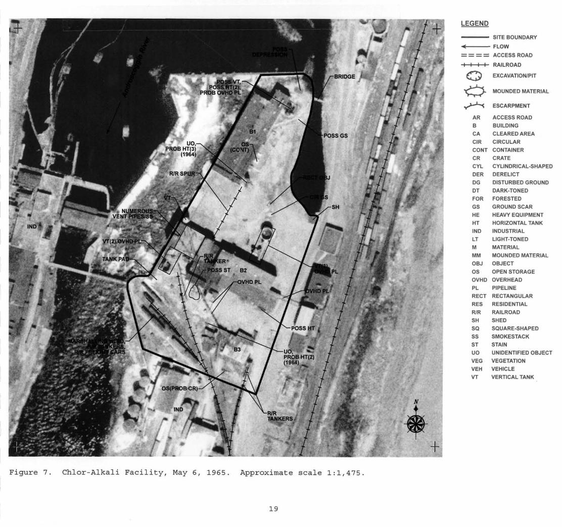
MAY 6, 1965 (FIGURE 7)
Buildings Bl, B2, and B3 and the small shed remain visible at the site
which does not appear to be active at this time. Connected to building Bl by a
lattice of probable overhead pipelines are a possible vertical storage tank and
two possible horizontal storage tanks. A linear, possible ground scar extends
from the building to near the bridge. In 1964, a pipeline, possible ditch, and
,a patch of dark-toned material were noted at this location. Near the bridge
there is a rectangular-shaped possible depression; in 1964 possible saturated
material was noted at this location. Containers remain at the open storage
area and an unidentified object (UO) is located alongside building Bl at the
terminus of the railroad spur remnant. This unidentified object is
approximately one-half the height of building Bl and located near to where
three probable horizontal storage tanks were seen in 1964.
The grouping of three vertical storage tanks (one of which is open-topped)
and a connecting overhead pipeline remain on the north side building B2. Just
north of these storage tanks are a rectangular-shaped object (REC OBJ) and a
circular-shaped ground scar (CIR GS). The symmetry of this ground scar
suggests the former location of a storage tank, but no tank was observed at the
location in 1955 or 1964. The grouping of two vertical storage tanks (one of
which appears open-topped), overhead pipelines, and large-diameter tank pad
remain in place alongside the Androscoggin River. The vertical storage tank
located on the northwest side of building B2 remains in place and a possible
horizontal storage tank is noted alongside the southeast side of the building.
Building B2 remains connected to an offsite building (not annotated) via an
overhead pipeline and overhead pipelines continue to connect building B2 to
building B3. Adjacent to building B3 is the open storage area housing small
probable crates. Also noted near this building is an unidentified object where
in 1964, two probable horizontal storage tanks were observed.
In the railroad marshalling yard there are numerous parked railroad tanker
cars and several freight cars. Additional railroad tanker cars are located
adjacent to building B3.
18
u
POSS VT, POSS NT(2),
PROB OVHD PL
UO, PROB HT(3)
(1964)
NUMEROUSVENT PtPES/SS-
ER-
/-POSSST B2
uo, PROB HT(2) (1964) _
*ti. "fct'
'/ *'•
' I&*V<7; *£*•* » .•&;*..,**
LEGEND
—— SITE BOUNDARY
<* FLOW
= = = = ACCESS ROAD
-H—h-4- RAILROAD
{T*$ EXCAVATION/PIT
MOUNDED MATERIAL
ESCARPMENT
AR ACCESS ROAD
B BUILDING
CA CLEARED AREA
CIR CIRCULAR
CONT CONTAINER
CR CRATE
CYL CYLINDRICAL-SHAPED
DER DERELICT
DG DISTURBED GROUND
DT DARK-TONED
FOR FORESTED
GS GROUND SCAR
HE HEAVY EQUIPMENT
HT HORIZONTAL TANK
IND INDUSTRIAL
LT LIGHT-TONED
M MATERIAL
MM MOUNDED MATERIAL
OBJ OBJECT
OS OPEN STORAGE
OVHD OVERHEAD
PL PIPELINE
RECT RECTANGULAR
RES RESIDENTIAL
R/R RAILROAD
SH SHED
SQ SQUARE-SHAPED
SS SMOKESTACK
ST STAIN
UO UNIDENTIFIED OBJECT
VEG VEGETATION
VEH VEHICLE
VT VERTICAL TANK
Figure 7. Chlor-Alkali Facility, May 6, 1965. Approximate scale 1:1,475.
19
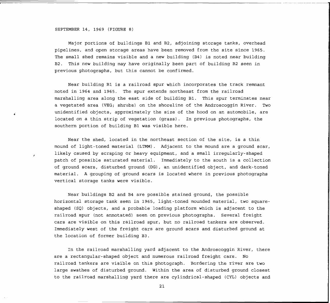
SEPTEMBER 14, 1969 (FIGURE 8)
Major portions of buildings Bl and B2, adjoining storage tanks, overhead
pipelines, and open storage areas have been removed from the site since 1965.
The small shed remains visible and a new building (B4) is noted near building
B2. This new building may have originally been part of building B2 seen in
previous photographs, but this cannot be confirmed.
Near building Bl is a railroad spur which incorporates the track remnant
noted in 1964 and 1965. The spur extends northeast from the railroad
marshalling area along the east side of building Bl. This spur terminates near
a vegetated area (VEG; shrubs) on the shoreline of the Androscoggin River. Two
unidentified objects, approximately the size of the hood on an automobile, are
located on a thin strip of vegetation (grass). In previous photographs, the
southern portion of building Bl was visible here.
Near the shed, located in the northeast section of the site, is a thin
mound of light-toned material (LTMM). Adjacent to the mound are a ground scar,
likely caused by scraping or heavy equipment, and a small irregularly-shaped
patch of possible saturated material. Immediately to the south is a collection
of ground scars, disturbed ground (DG), an unidentified object, and dark-toned
material. A grouping of ground scars is located where in previous photographs
vertical storage tanks were visible.
Near buildings B2 and B4 are possible stained ground, the possible
horizontal storage tank seen in 1965, light-toned mounded material, two square-
shaped (SQ) objects, and a probable loading platform which is adjacent to the
railroad spur (not annotated) seen on previous photographs. Several freight
cars are visible on this railroad spur, but no railroad tankers are observed.
Immediately west of the freight cars are ground scars and disturbed ground at
the location of former building B3.
In the railroad marshalling yard adjacent to the Androscoggin River, there
are a rectangular-shaped object and numerous railroad freight cars. No
railroad tankers are visible on this photograph. Bordering the river are two
large swathes of disturbed ground. Within the area of disturbed ground closest
to the railroad marshalling yard there are cylindrical-shaped (CYL) objects and
21

possible dumping activity. The second area of disturbed ground just to the
north includes possible ground stains. Part of this area of disturbed ground
was formerly occupied by a section of building B2.
22

LEGEND
-^—— SITE BOUNDARY
•< FLOW
= = = = ACCESS ROAD
I I I I RAILROAD
{T*^ EXCAVATION/PIT
MOUNDED MATERIAL
ESCARPMENT
bi
AR
B
ACCESS ROAD
BUILDING
CA CLEARED AREA
CIR CIRCULAR
CONT CONTAINER
CR CRATE
CYL CYLINDRICAL-SHAPED DER DERELICT
DG DISTURBED GROUND
DT DARK-TONED
1 FOR FORESTED 1 GS GROUND SCAR
HE HEAVY EQUIPMENT HT HORIZONTAL TANK
1 IND
LT
INDUSTRIAL
LIGHT-TONED 1 1
M MATERIAL
MM MOUNDED MATERIAL
OBJ OBJECT
OS OPEN STORAGE
OVHD OVERHEAD
PL PIPELINE
RECT RECTANGULAR
# ̂ ^ \-LTMM PROB '
LOADING
RES
R/R
SH
RESIDENTIAL
RAILROAD
SHED PLATFORM SQ SQUARE-SHAPED
SS SMOKESTACK ST STAIN uo UNIDENTIFIED OBJECT
VEG VEGETATION
VEH VEHICLE
VT VERTICAL TANK
Figure 8. Chlor-Alkali Facility, September 14, 1969. Approximate scale 1:1,505.
u 23
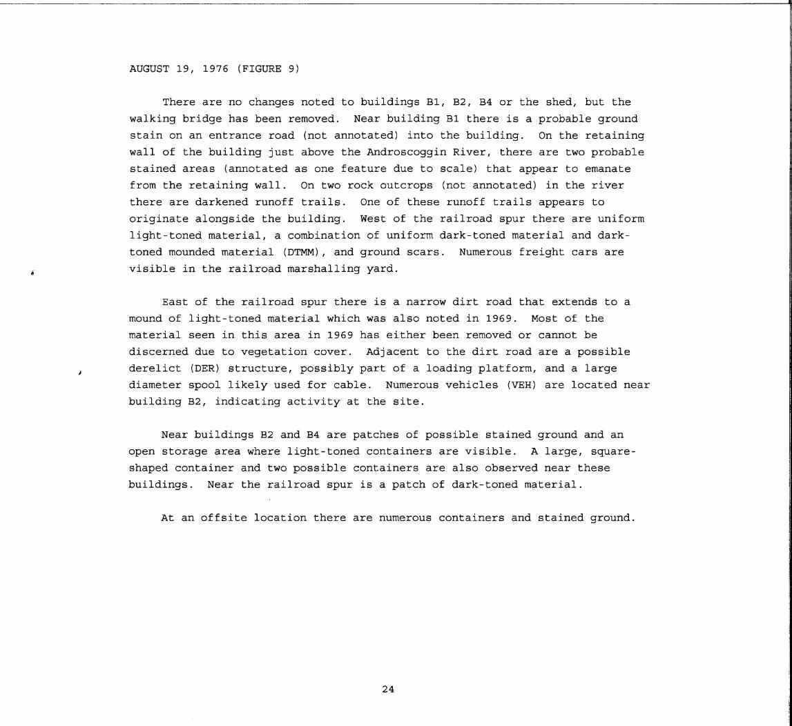
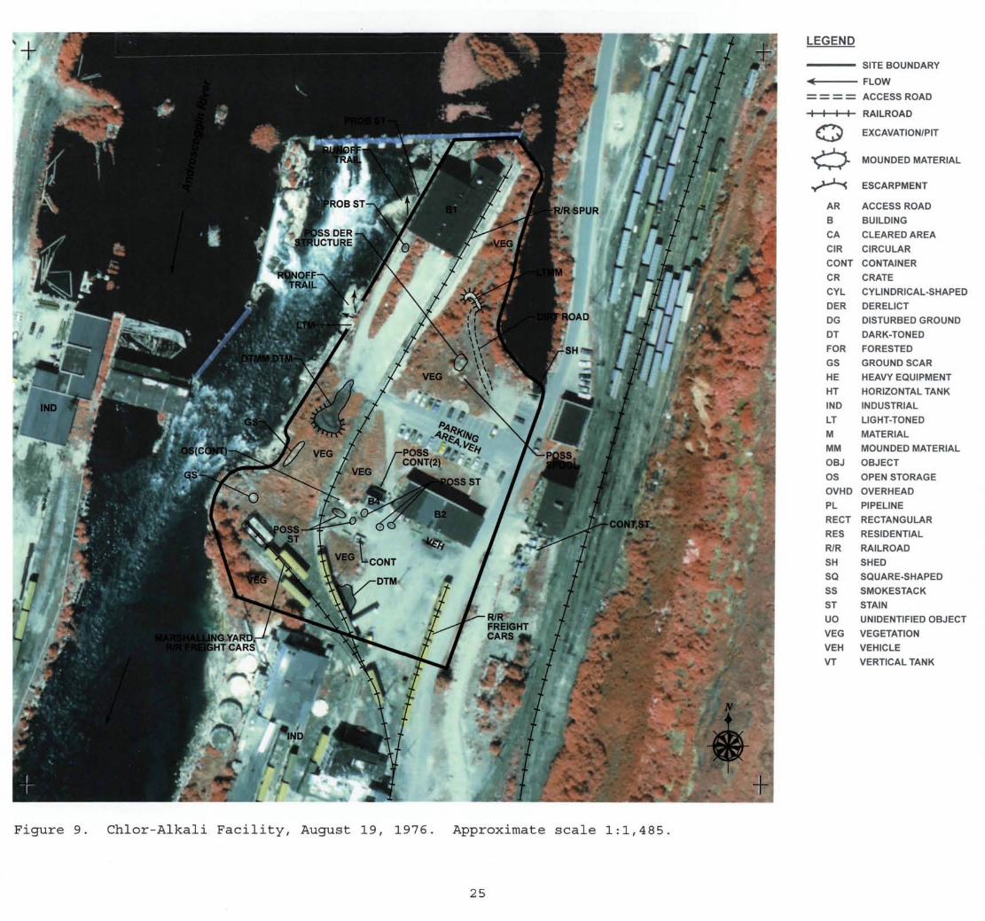
AUGUST 19, 1976 (FIGURE 9)
There are no changes noted to buildings Bl, B2, B4 or the shed, but the
walking bridge has been removed. Near building Bl there is a probable ground
stain on an entrance road (not annotated) into the building. On the retaining
wall of the building just above the Androscoggin River, there are two probable
stained areas (annotated as one feature due to scale) that appear to emanate
from the retaining wall. On two rock outcrops (not annotated) in the river
there are darkened runoff trails. One of these runoff trails appears to
originate alongside the building. West of the railroad spur there are uniform
light-toned material, a combination of uniform dark-toned material and dark-
toned mounded material (DTMM), and ground scars. Numerous freight cars are
visible in the railroad marshalling yard.
East of the railroad spur there is a narrow dirt road that extends to a
mound of light-toned material which was also noted in 1969. Most of the
material seen in this area in 1969 has either been removed or cannot be
discerned due to vegetation cover. Adjacent to the dirt road are a possible
derelict (DER) structure, possibly part of a loading platform, and a large
diameter spool likely used for cable. Numerous vehicles (VEH) are located near
building B2, indicating activity at the site.
Near buildings B2 and B4 are patches of possible stained ground and an
open storage area where light-toned containers are visible. A large, square-
shaped container and two possible containers are also observed near these
buildings. Near the railroad spur is a patch of dark-toned material.
At an offsite location there are numerous containers and stained ground.
24
LEGEND
SITE BOUNDARY
< FLOW
= = = = ACCESS ROAD
I I I I RAILROAD
£T*$ EXCAVATION/PIT
MOUNDED MATERIAL
ESCARPMENT
AR ACCESS ROAD
B BUILDING
CA CLEARED AREA
CIR CIRCULAR
CONT CONTAINER
CR CRATE
CYL CYLINDRICAL-SHAPED
DER DERELICT
DG DISTURBED GROUND
DT DARK-TONED
FOR FORESTED
GS GROUND SCAR
HE HEAVY EQUIPMENT
HT HORIZONTAL TANK
IND INDUSTRIAL
LT LIGHT-TONED
M MATERIAL
MM MOUNDED MATERIAL
OBJ OBJECT
OS OPEN STORAGE
OVHD OVERHEAD
PL PIPELINE
RECT RECTANGULAR
RES RESIDENTIAL
R/R RAILROAD
SH SHED
SQ SQUARE-SHAPED
SS SMOKESTACK
ST STAIN
UO UNIDENTIFIED OBJECT
VEG VEGETATION
VEH VEHICLE
VT VERTICAL TANK
Figure 9. Chlor-Alkali Facility, August 19, 1976. Approximate scale 1:1,485.
25
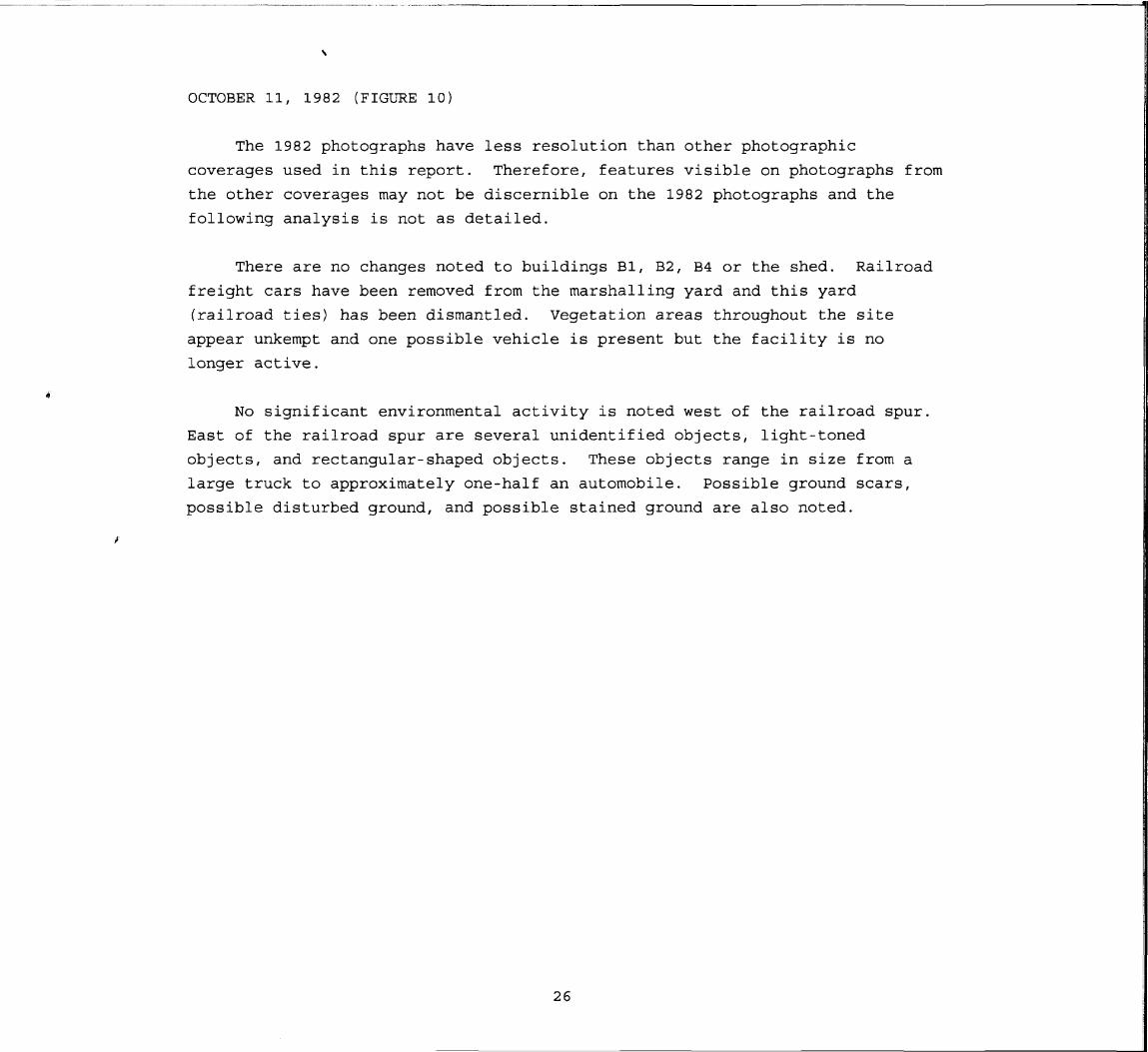
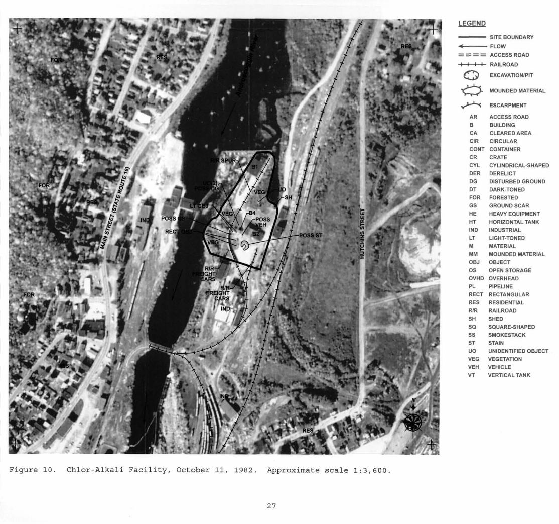
OCTOBER 11, 1982 (FIGURE 10)
The 1982 photographs have less resolution than other photographic
coverages used in this report. Therefore, features visible on photographs from
the other coverages may not be discernible on the 1982 photographs and the
following analysis is not as detailed.
There are no changes noted to buildings Bl, B2, B4 or the shed. Railroad
freight cars have been removed from the marshalling yard and this yard
(railroad ties) has been dismantled. Vegetation areas throughout the site
appear unkempt and one possible vehicle is present but the facility is no
longer active.
No significant environmental activity is noted west of the railroad spur.
East of the railroad spur are several unidentified objects, light-toned
objects, and rectangular-shaped objects. These objects range in size from a
large truck to approximately one-half an automobile. Possible ground scars,
possible disturbed ground, and possible stained ground are also noted.
26
LEGEND
——— SITE BOUNDARY
«< FLOW
= = === ACCESS ROAD
I I I I
£T7^
AR
B
CA
CIR
CONT
CR
CYL
DER
DG
DT
FOR
GS
HE
HT
IND
LT
M
MM
OBJ
OS
OVHD
PL
RECT
RES
R/R
SH
SQ
SS
ST
UO
VEG
VEH
VT
RAILROAD
EXCAVATION/PIT
MOUNDED MATERIAL
ESCARPMENT
ACCESS ROAD
BUILDING
CLEARED AREA
CIRCULAR
CONTAINER
CRATE
CYLINDRICAL-SHAPED
DERELICT
DISTURBED GROUND
DARK-TONED
FORESTED
GROUND SCAR
HEAVY EQUIPMENT
HORIZONTAL TANK
INDUSTRIAL
LIGHT-TONED
MATERIAL
MOUNDED MATERIAL
OBJECT
OPEN STORAGE
OVERHEAD
PIPELINE
RECTANGULAR
RESIDENTIAL
RAILROAD
SHED
SQUARE-SHAPED
SMOKESTACK
STAIN
UNIDENTIFIED OBJECT
VEGETATION
VEHICLE
VERTICAL TANK
Figure 10. Chlor-Alkali Facility, October 11, 1982. Approximate scale 1:3,600.
27

MAY 13, 1986 (FIGURE 11)
The 1986 photographs have less resolution than other photographic
coverages used in this report. Therefore, features visible on photographs from
the other coverages may not be discernible on the 1986 photographs and the
following analysis is not as detailed.
There are no changes noted to buildings Bl, B2, B4 or the shed.
Vegetation areas throughout the site appear unkempt. Several vehicles, a
possible vehicle, and railroad freight cars are visible on the railroad spur
but the facility is no longer active.
No significant environmental activity is noted west of the railroad spur.
East of the railroad spur is an unidentified object approximately one-half the
size of an automobile.
28

LEGEND /
——— SITE BOUNDARY
•< FLOW
= = = = ACCESS ROAD
I I I I RAILROAD
£T*^ EXCAVATION/PIT
MOUNDED MATERIAL
ESCARPMENT
AR ACCESS ROAD
B BUILDING
CA CLEARED AREA
CIR CIRCULAR
CONT CONTAINER
CR CRATE
> CYL CYLINDRICAL-SHAPED
DER DERELICT
DG DISTURBED GROUND
DT DARK-TONED
VEG FOR FORESTED
GS GROUND SCAR
tm ^H HE
HT
HEAVY EQUIPMENT
HORIZONTAL TANK
MP
IND
LT
M
INDUSTRIAL
LIGHT-TONED
MATERIAL
MM MOUNDED MATERIAL
OBJ OBJECT
OS OPEN STORAGE
OVHD OVERHEAD
PL PIPELINE
RECT RECTANGULAR
RES RESIDENTIAL VEG
R/R RAILROAD
SH SHED
SQ SQUARE-SHAPED
SS SMOKESTACK
ST STAIN
UO UNIDENTIFIED OBJECT
VEG VEGETATION
VEH VEHICLE
VT VERTICAL TANK
* " **> » ;/ '.*»* * <
%v/% RES t Of- V
Figure 11. Chlor-Alkali Facility, May 13, 1986. Approximate scale 1:3,560.
29

MAY 14, 1994 (FIGURE 12)
The 1994 photographs have less resolution than other photographic
coverages used in this report. Therefore, features visible on photographs from
the other coverages may not be discernible on the 1994 photographs and the
following analysis is not as detailed.
There are no changes noted to buildings Bl, B2, B4 or the shed; however,
all railroad lines have been removed from the site. Vegetation areas
throughout the site appear unkempt. Two semi-trailers, possible heavy
equipment (HE), and a vehicle are noted at the site. Near the trailers are
light-toned mounded material and a large cleared area (CA) which forms a
depression. Several small, unidentified objects are noted within this cleared
depression. Near buildings B2 and B4 are a larger unidentified object and an
open storage area where crates or containers are neatly arranged in three
evenly spaced rows.
30

LEGEND
—— SITE BOUNDARY
-< FLOW
= = = = ACCESS ROAD
l i l t RAILROAD
{T*^ EXCAVATION/PIT
MOUNDED MATERIAL
ESCARPMENT
AR ACCESS ROAD
B BUILDING
CA CLEARED AREA
CIR CIRCULAR
CONT CONTAINER
CR CRATE
CYL CYLINDRICAL-SHAPED
DER DERELICT
OG DISTURBED GROUND
DT DARK-TONED
FOR FORESTED
GS GROUND SCAR
HE HEAVY EQUIPMENT
HT HORIZONTAL TANK
IND INDUSTRIAL
LT LIGHT-TONED
M MATERIAL
MM MOUNDED MATERIAL
OBJ OBJECT
OS OPEN STORAGE
OVHD OVERHEAD
PL PIPELINE
RECT RECTANGULAR
RES RESIDENTIAL
R/R RAILROAD
SH SHED
SQ SQUARE-SHAPED
SS SMOKESTACK
ST STAIN
UO UNIDENTIFIED OBJECT
VEG VEGETATION
VEH VEHICLE
VT VERTICAL TANK
Figure 12. Chlor-Alkali Facility, May 14, 1994. Approximate scale 1:3,600.
31

FRACTURE TRACE ANALYSIS
Fracture trace analysis is the technique of using aerial imagery for
locating fracture traces or geologic lineaments on the earth's surface based on
the photo-geologic signatures such as soil-tonal variations and vegetational
and topographic alignments. Fracture traces are considered to be the surface
expressions of vertical-to-near-vertical zones of fracture concentration in
bedrock (see Methodology section).
The fracture trace study area analyzed for this report covers an
approximate 41 square kilometer (16 square miles) area, centered on the Chlor-
Alkali Facility. The study area is located in Coos County, New Hampshire, and
is situated in the New England physiographic province. The bedrock geology of
the study area includes Ordovician age metamorphosed biotite-quartz monzonite
of the Oliverian Plutonic Suite which underlies the Androscoggin River valley.
The surrounding uplands in the study area are underlain by Ordovician age
gneisses and amphibolites of the Ammonnoosuc Volcanics. The rocks of the
Oliverian Plutonic Suite intrude those of the Ammonnoosuc Volcanics (Degnan,
J.R., et al., 2005).
The fracture trace analysis was conducted using 1964 large-scale
photographs (1:18,000 scale), 1982 medium-scale photographs (1:40,000 scale),
and geologic literature describing the area. A total of seven (7) fracture
traces were identified and are presented on an overlay to a print produced from
a 1986 photograph (see Figure 13). Two lineaments are presented in a study by
Degnan, J.R., et al., (2005). One lineament is located north of the Chlor-
Alkali Facility along the east bank of the Androscoggin River and the other in
the upland area southeast of the facility. These two lineaments were
identified using high altitude aerial photography with an approximate scale of
1:80,000 (Degnan, J.R. et al., 2005). An unsuccessful effort was made to
corroborate the location of these two lineaments on the medium- to large-scale
photographs used in this report. The lack of success may be attributable to
the differences in the scale of photography used in the separate studies.
33

All of the seven fracture traces identified in this fracture trace
analysis are situated in the upland portion of the study area and are underlain
by Ammonnoosuc Volcanics. Urban development along the Androscoggin River
valley has obscured or destroyed any evidence of fracture traces in the area
underlain by the Oliverian Plutonics. None of the seven fracture traces were
identified extending across the interface between the two bedrock units
(Oliverian Plutonics and Ammonnoosuc Volcanics) underlying the study area.
Therefore no fracture trace induced hydrologic connectivity between the bedrock
units can be inferred from this analysis. However, if fracture traces "A" and
"B" (see Figure 13) are extended to the northwest into the Oliverian Plutonics
of the urban developed lowland area, the two extended traces intersect at the
Androscoggin River near the southwest corner of the Chlor-Alkali Facility.
This intersection point may possibly identify a zone of fractured bedrock that
preferentially directs ground-water flow toward the facility.
Caution, however, should be exercised if the fracture traces identified in
this analysis and annotated on Figure 13 are to be used for determining the
placement of groundwater monitoring wells. Differences of a few meters can
determine whether or not a well is located on a given fracture trace. Thus, it
is recommended that the geologic field personnel tasked with determining the
placement of the wells utilize stereo diapositives and photographic
interpretive equipment as part of their field operations.
34

LEGEND
—^— SITE BOUNDARY
< FLOW
CHLOR-ALKALI = = = = ACCESS ROAD
FRACTURE TRACE STUDY AR I I I I RAILROAD
^T*^ EXCAVATION/PIT
MOUNDED MATERIAL
ESCARPMENT
AR ACCESS ROAD
B BUILDING CA CLEARED AREA
CIR CIRCULAR
CONT CONTAINER
CR CRATE
CYL CYLINDRICAL-SHAPED
DER DERELICT
DG DISTURBED GROUND
DT DARK-TONED CHLOR-ALKftL FOR FORESTED
FACILI GS GROUND SCAR
HE HEAVY EQUIPMENT
HT HORIZONTAL TANK
IND INDUSTRIAL
LT LIGHT-TONED
M MATERIAL
MM MOUNDED MATERIAL
OBJ OBJECT
OS OPEN STORAGE
OVHD OVERHEAD
PL PIPELINE
RECT RECTANGULAR
RES RESIDENTIAL
R/R RAILROAD
SH SHED tm SQ SQUARE-SHAPED
SS SMOKESTACK MD. i&v*v.mJ i ST STAIN
UO UNIDENTIFIED OBJECT R/ver,
VEG VEGETATION
VEH VEHICLE
VT VERTICAL TANK
Figure 13. Chlor-Alkali Facility, fracture trace analysis, May 13, 1986.Approximate scale 1:35,110.
35

GLOSSARY
Access Road (AR) - A paved or unpaved route of vehicular access.
Building (B) - A relatively permanent, essentially boxlike construction havinga roof.
Cleared Area (CA) - An area from which man has removed trees, shrubs, or othernatural vegetative cover.
Container (CONT) - Any portable device in which material is stored,transported, handled, or disposed.
Dark- (DT). Medium- (MT). or Light-Toned (LT) - Tones of features in questionare compared with the darkest and lightest tones of gray (if using B&Wphotography) on the print.
Disturbed Ground (DG) - A rough area where the ground surface has been dug upor overturned.
Ground Scar (GS) - An area of bare soil, apparently the result of humanactivity.
Material (M) - Raw or waste materials on or in the vicinity of the site.
Mounded Material (MM) - Piles of raw or waste materials on or in the vicinityof the site.
Open Storage Area (OS) - An area of open-air (outdoor) storage ofcontainerized, raw or waste materials, within industrial or manufacturingsites.
Stain (ST) - A residue or discoloration resulting from a spill, discharge, orremoved/dispersed materials.
Tanks - Vertical tanks (VT), horizontal tanks (HT), pressure tanks (PT), tankfarms, and solid waste management units. A large receptacle, container, orstructure for holding liquid or gas.
37
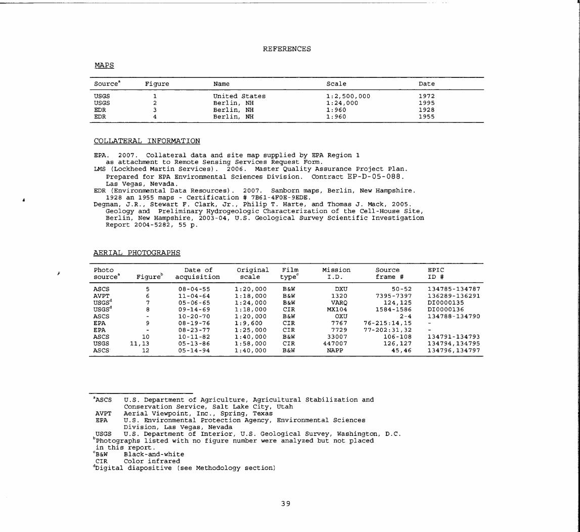
REFERENCES
MAPS
Source Figure Name Scale Date
USGS 1 United States 1:2,500,000 1972USGS 2 Berlin, NH 1:24,000 1995EDR 3 Berlin, NH 1:960 1928EDR 4 Berlin, NH 1:960 1955
COLLATERAL INFORMATION
EPA. 2007. Collateral data and site map supplied by EPA Region 1as attachment to Remote Sensing Services Request Form.
LMS (Lockheed Martin Services). 2006. Master Quality Assurance Project Plan.Prepared for EPA Environmental Sciences Division. Contract EP-D-05-088.Las Vegas, Nevada.
EDR (Environmental Data Resources). 2007. Sanborn maps, Berlin, New Hampshire.1928 an 1955 maps - Certification # 7B61-4FOE-9EDE.
Degnan, J.R., Stewart F. Clark, Jr., Philip T. Harte, and Thomas J. Mack, 2005.Geology and Preliminary Hydrogeologic Characterization of the Cell-House Site,Berlin, New Hampshire, 2003-04, U.S. Geological Survey Scientific InvestigationReport 2004-5282, 55 p.
AERIAL PHOTOGRAPHS
Photo source 3 Figureb
Date of acquisition
Original scale
Film typec
Mission I.D.
Source frame #
EPIC ID #
ASCS 5 08-04-55 1:20,000 B&W DXU 50-52 134785-134787 AVPT USGSd
USGSd
6 7 8
11-04-64 05-06-65 09-14-69
1:18,000 1:24, 000 1:18,000
B&W B&W CIR
1320 VARQ MX104
7395-7397 124,125
1584-1586
136289-136291 DI0000135 DI0000136
ASCS - 10-20-70 1:20,000 B&W OXU 2-4 134788-134790 EPA 9 08-19-76 1:9,600 CIR 7767 76-215:14,15 -EPA - 08-23-77 1:25, 000 CIR 7729 77-202:31,32 -ASCS 10 10-11-82 1:40, 000 B&W 33007 106-108 134791-134793 USGS 11,13 05-13-86 1:58,000 CIR 447007 126, 127 134794,134795 ASCS 12 05-14-94 1:40,000 B&W NAPP 45,46 134796, 134797
ASCS U.S. Department of Agriculture, Agricultural Stabilization andConservation Service, Salt Lake City, Utah
AVPT Aerial Viewpoint, Inc., Spring, TexasEPA U.S. Environmental Protection Agency, Environmental Sciences
Division, Las Vegas, NevadaUSGS U.S. Department of Interior, U.S. Geological Survey, Washington, D.C.^Photographs listed with no figure number were analyzed but not placedin this report.
CB&W Black-and-whiteCIR Color infrared
dDigital diapositive (see Methodology section)
39


