AE 245 homework #4 solutions
30
AE 245 homework #4 solutions Tim Smith 14 February 2000 1 Problem 1 Consider a general aviation aircraft with weight of 3300 lbs and wing surface area of 310 ft 2 . It is powered by a piston engine that provides a maximum of 250 hp at sea level and a conventional propeller that operates at 80% efficiency. The aerodynamic properties of the aircraft are described by a parabolic drag polar with C D 0 02 0 06C 2 L (1) 1. What is the power level required to maintain a steady flight path angle of 3 degrees and an air speed of 220 ft/s at sea level? 2. Assume the aircraft flies with a flight path angle of 3 degrees using maximum available power. Determine all possible air speeds which maintain steady flight at sea level. 3. What is the minimum power level required to maintain steady climb rate of 10 ft/s at sea level? What is the corresponding air speed? 4. Plot the maximum steady climb rate of the aircraft as it depends on altitude from sea level to 20,000 ft. Plot the corresponding air speed as it depends on altitude. 5. Plot the minimum glide angle which maintains steady gliding flight as it depends on altitude from sea level to 20,000 ft. Plot the corresponding air speed as it depends on altitude. 1.1 Required power at γ 3 , 220 ft/s At V 220 ft/s and sea level, the dynamic pressure q 1 2 ρV 2 1 2 2 3769 10 3 220 2 lb ft 2 57 521 lb ft 2 (2) and the lift coefficient C L W qS 3300 57 521 310 0 18507 (3) so the required power for steady level flight 1
Transcript of AE 245 homework #4 solutions

AE 245 homework #4 solutions
Tim Smith
14 February 2000
1 Problem 1
Consider a general aviation aircraft with weight of 3300 lbs and wing surface area of 310 ft2. It is powered by a pistonengine that provides a maximum of 250 hp at sea level and a conventional propeller that operates at 80% efficiency.The aerodynamic properties of the aircraft are described by a parabolic drag polar with
CD = 0:02+0:06C2L (1)
1. What is the power level required to maintain a steady flight path angle of 3 degrees and an air speed of 220 ft/sat sea level?
2. Assume the aircraft flies with a flight path angle of 3 degrees using maximum available power. Determine allpossible air speeds which maintain steady flight at sea level.
3. What is the minimum power level required to maintain steady climb rate of 10 ft/s at sea level? What is thecorresponding air speed?
4. Plot the maximum steady climb rate of the aircraft as it depends on altitude from sea level to 20,000 ft. Plot thecorresponding air speed as it depends on altitude.
5. Plot the minimum glide angle which maintains steady gliding flight as it depends on altitude from sea level to20,000 ft. Plot the corresponding air speed as it depends on altitude.
1.1 Required power atγ= 3�, 220 ft/s
At V = 220 ft/s and sea level, the dynamic pressure
q� 12
ρV2 =12(2:3769�10�3)(220)2 lb
ft2 = 57:521lbft2 (2)
and the lift coefficient
CL =WqS
=3300
57:521(310)= 0:18507 (3)
so the required power for steady level flight
1

Pr = qSV�CDo+KC2
L
�=
57:521(310)220550
�0:02+0:06(0:18507)2� hp= 157:31 hp (4)
Since lift equals weight for steady climbing flight, excess powerPx is related to rate of climbRC=V sinγ by
Px � Pa�Pr =WVsinγ =3300(220)sin3�
550hp= 69:083 hp (5)
Thus, the engine shaft horsepower required for climbing flight at the given flight path angleγ and air speedV is
Ps =Pr +Px
η=
157:31+69:0830:8
hp= 282:99 hp (6)
which is 13.2% higher than the maximum available shaft horsepower.
1.2 Air speed atγ= 3�, Pmax
For a maximum available power
Pa;max= ηPs;max= 0:8(250) hp= 200 hp (7)
the possible air speeds for climbing flight are given by finding the roots of
f (V) = Pa;max�qSV�CDo+KC2
L
��WVsinγ (8)
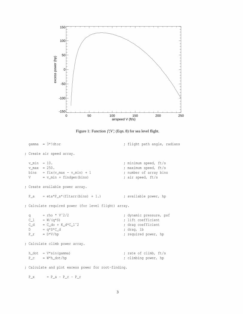
The two roots of this, as shown in Fig 1, are at
V� = 16:588 ft=s
V+ = 207:30 ft=s
The following IDL code plots this function :
pro hw4_1b
; Define initial conditions & conversions.
hp = 550. ; 1 hp in ft-lb/srho = 2.3769e-3 ; sea level density, slug/ftˆ3W = 3300. ; aircraft weight, lbS = 310. ; wing area, ftˆ2P_s = 250. ; engine shaft power, hpeta = 0.80 ; propeller efficiencyC_do = 0.02 ; parasitic drag coefficientK_d = 0.06 ; induced drag factor, 1/pi e AR
2
0 50 100 150 200 250airspeed V (ft/s)
-150
-100
-50
0
50
100
150
exce
ss p
ower
(hp
)
Figure 1: Functionf (V) (Eqn. 8) for sea level flight.
gamma = 3*!dtor ; flight path angle, radians
; Create air speed array.
v_min = 10. ; minimum speed, ft/sv_max = 250. ; maximum speed, ft/sbins = fix(v_max - v_min) + 1 ; number of array binsV = v_min + findgen(bins) ; air speed, ft/s
; Create available power array.
P_a = eta*P_s*(fltarr(bins) + 1.) ; available power, hp
; Calculate required power (for level flight) array.
q = rho * Vˆ2/2 ; dynamic pressure, psfC_l = W/(q*S) ; lift coefficientC_d = C_do + K_d*C_lˆ2 ; drag coefficientD = q*S*C_d ; drag, lbP_r = D*V/hp ; required power, hp
; Calculate climb power array.
h_dot = V*sin(gamma) ; rate of climb, ft/sP_c = W*h_dot/hp ; climbing power, hp
; Calculate and plot excess power for root-finding.
P_x = P_a - P_c - P_r
3
xtitle = ’airspeed V (ft/s)’ ; x-axis titleytitle = ’excess power (hp)’ ; y-axis titlefile = ’fig4_1b.eps’ ; file namescale = 1.0xsz = 4.0*scaleysz = 3.0*scale
set_plot, ’ps’ ; set plot device to PostScriptdevice,/encapsulated,/preview,filename=file ; open file & save EPSdevice,/inches, xsize=xsz, ysize=ysz, $
font_size = 7plot, V, P_x, xtitle=xtitle, $
ytitle=ytitle, font=0device, /close ; close the file
end
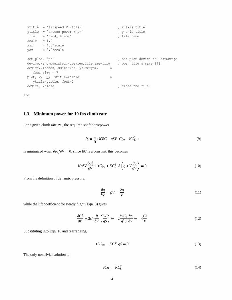
1.3 Minimum power for 10 ft/s climb rate
For a given climb rateRC, the required shaft horsepower
Ps =1η�WRC+qSV
�CDo+KC2
L
��(9)
is minimized when∂Ps=∂V = 0; sinceRC is a constant, this becomes
KqSV∂C2
L
∂V+�CDo+KC2
L
�S
�q+V
∂q∂V
�= 0 (10)
From the definition of dynamic pressure,
∂q∂V
= ρV =2qV
(11)
while the lift coefficient for steady flight (Eqn. 3) gives
∂C2L
∂V= 2CL
∂∂V
�WqS
�=�2
WCL
q2S∂q∂V
=�4C2
L
V(12)
Substituting into Eqn. 10 and rearranging,
�3CDo�KC2
L
�qS= 0 (13)
The only nontrivial solution is
3CDo = KC2L (14)
4
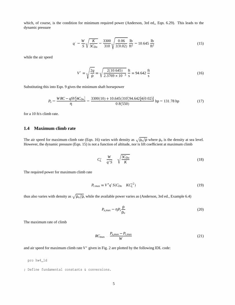
which, of course, is the condition for minimum required power (Anderson, 3rd ed,, Eqn. 6.29). This leads to thedynamic pressure
q� =WS
rK
3CDo=
3300310
s0:06
3(0:02)lbft2 = 10:645
lbft2 (15)
while the air speed
V� =
s2qρ
=
r2(10:645)
2:3769�10�3
fts= 94:642
fts
(16)
Substituting this into Eqn. 9 gives the minimum shaft horsepower
Ps =WRC�qSV[4CDo]
η=
3300(10)+10:645(310)94:642[4(0:02)]0:8(550)
hp= 131:78 hp (17)
for a 10 ft/s climb rate.
1.4 Maximum climb rate
The air speed for maximum climb rate (Eqn. 16) varies with density asp
ρo=ρ whereρo is the density at sea level.However, the dynamic pressure (Eqn. 15) is not a function of altitude, nor is lift coefficient at maximum climb
C�
L =Wq�S
=
r3CDo
K(18)
The required power for maximum climb rate
Pr;max=V�q�S(CDo+KC�
L2) (19)
thus also varies with density asp
ρo=ρ, while the available power varies as (Anderson, 3rd ed., Example 6.4)
Pa;max= ηPsρρo
(20)
The maximum rate of climb
RCmax=Pa;max�Pr;max
W(21)
and air speed for maximum climb rateV� given in Fig. 2 are plotted by the following IDL code:
pro hw4_1d
; Define fundamental constants & conversions.
5

0 5 10 15 20altitude (1000 ft)
95
100
105
110
115
120
125
airs
peed
V*
(ft/s
)
0 5 10 15 20altitude (1000 ft)
10
15
20
25
rate
of c
limb
(ft/s
)
Figure 2: Maximum climb rate and airspeed at max climb as a function of altitude.
R = 1716. ; air gas constant, ft-lb/slug-RT_z = 459.67 ; 0 F in Rg_o = 32.174 ; std gee, ft/sˆ2km2ft = 3280.8 ; 1 km in ftm2ft = km2ft/1000. ; 1 m in ftK2R = 1.8 ; 1 K in Rhp = 550. ; 1 hp in ft-lb/s
; Define initial conditions.
p_sl = 2116.2 ; sea level pressure, lb/ftˆ2T_sl = 518.69 ; sea level temperature, Rrho_sl = 2.3769e-3 ; sea level density, slug/ftˆ3a_1 = -6.5e-3*K2R/m2ft ; lapse rate, R/ft
6
W = 3300. ; aircraft weight, lbS = 310. ; wing area, ftˆ2P_s = 250. ; engine shaft power, hpeta = 0.80 ; propeller efficiencyC_do = 0.02 ; parasitic drag coefficientK_d = 0.06 ; induced drag factor, 1/pi e AR
; Create gradient layer altitude, temperature, pressure & density arrays.
bins = 201. ; number of array binsh = 100.*findgen(bins) ; altitude in gradient layer, ftT = T_sl + a_1*h ; temperature in gradient layer, Rp = p_sl*(T/T_sl)ˆ(-g_o/(a_1*R)) ; pressure in gradient layer, lb/ftˆ2rho = p/(R*T) ; density in gradient layer, slug/ftˆ3
; Calculate and plot air speed for max steady climb as function of altitude.
r1 = sqrt(K_d/(3.*C_do))r2 = (2.*W)/(rho*S)V_star = sqrt(r1*r2) ; max climb air speed, ft/sq_star = W*r1/S ; max climb dynamic pressure, lb/ftˆ2
xtitle = ’altitude (1000 ft)’ ; x-axis titleytitle = ’airspeed V* (ft/s)’ ; y-axis titlefile = ’fig4_1dv.eps’ ; file namescale = 1.0xsz = 4.0*scaleysz = 3.0*scale
set_plot, ’ps’ ; set plot device to PostScriptdevice,/encapsulated,/preview,filename=file ; open file & save EPSdevice,/inches, xsize=xsz, ysize=ysz, $
font_size = 7plot, h/1000., V_star, xtitle=xtitle, $
ytitle=ytitle, font=0, $xstyle = 1, ystyle = 1
device, /close ; close the file
; Calculate and plot required power, available power and maximum rate of climb.
C_L = W/(q_star*S) ; max climb lift coefficientC_D = C_do + K_d*C_Lˆ2 ; max climb drag coefficientP_r = q_star*S*C_D*V_star ; required power, ft-lb/sP_a = (rho/rho_sl)*eta*P_s*hp ; available power, ft-lb/sRC = (P_a - P_r)/W ; max rate of climb, ft/s
ytitle = ’rate of climb (ft/s)’ ; y-axis titlefile = ’fig4_1dr.eps’ ; file namescale = 1.0xsz = 4.0*scaleysz = 3.0*scale
set_plot, ’ps’ ; set plot device to PostScriptdevice,/encapsulated,/preview,filename=file ; open file & save EPSdevice,/inches, xsize=xsz, ysize=ysz, $
7

font_size = 7plot, h/1000., RC, xtitle=xtitle, $
ytitle=ytitle, font=0, $xstyle = 1, ystyle = 1
device, /close ; close the file
end
1.5 Minimum glide angle
The glide angleγg =�γ is given (for smallγ) by
γg =DW
=qSW
(CDo+KC2L) (22)
Setting the derivative with respect to air speed to zero,
∂γg
∂V=
SW
CD∂q∂V
+qSW
KS
�2CL
∂CL
∂V
�= 0 (23)
we can substitute derivatives from Eqn. 11 and Eqn. 12, yielding
∂γg
∂V=
2qSWV
�CD�2KC2
L
�= 0 (24)
The only nontrivial solution is at
CD =CDo+KC2L = 2KC2
L (25)
Thus, the lift coefficient for minimum glide angle is
CL =
rCDo
K(26)
Since Eqn. 3 holds forall steady linear flight (level, climbing or descending), the dynamic pressure
q=WS
rK
CDo(27)
so the minimum glide angle
γg;min =WS
rK
CDo
SW
(2CDo) = 2p
KCDo = 6:928�10�2 rad= 3:970� (28)
Note that neither the dynamic pressure nor the minimum glide angle are functions of density (and thus altitude).However, the velocity at minimum glide angle
8

V =
s2qρ
=
s2WρS
rK
CDo(29)
does vary with density, as shown in Fig. 3.
0 5 10 15 20altitude (1000 ft)
130
140
150
160
170
airs
peed
V (
ft/s)
0 5 10 15 20altitude (1000 ft)
3.0
3.5
4.0
4.5
5.0
rate
of c
limb
(ft/s
)
Figure 3: Minimum glide angle and airspeed at minimum glide angle as a function of altitude.
pro hw4_1d
; Define fundamental constants & conversions.
R = 1716. ; air gas constant, ft-lb/slug-RT_z = 459.67 ; 0 F in Rg_o = 32.174 ; std gee, ft/sˆ2km2ft = 3280.8 ; 1 km in ft
9

m2ft = km2ft/1000. ; 1 m in ftK2R = 1.8 ; 1 K in Rhp = 550. ; 1 hp in ft-lb/s
; Define initial conditions.
p_sl = 2116.2 ; sea level pressure, lb/ftˆ2T_sl = 518.69 ; sea level temperature, Rrho_sl = 2.3769e-3 ; sea level density, slug/ftˆ3a_1 = -6.5e-3*K2R/m2ft ; lapse rate, R/ftW = 3300. ; aircraft weight, lbS = 310. ; wing area, ftˆ2P_s = 250. ; engine shaft power, hpeta = 0.80 ; propeller efficiencyC_do = 0.02 ; parasitic drag coefficientK_d = 0.06 ; induced drag factor, 1/pi e AR
; Create gradient layer altitude, temperature, pressure & density arrays.
bins = 201. ; number of array binsh = 100.*findgen(bins) ; altitude in gradient layer, ftT = T_sl + a_1*h ; temperature in gradient layer, Rp = p_sl*(T/T_sl)ˆ(-g_o/(a_1*R)) ; pressure in gradient layer, lb/ftˆ2rho = p/(R*T) ; density in gradient layer, slug/ftˆ3
; Calculate and plot air speed for max steady climb as function of altitude.
r1 = sqrt(K_d/(3.*C_do))r2 = (2.*W)/(rho*S)V_star = sqrt(r1*r2) ; max climb air speed, ft/sq_star = W*r1/S ; max climb dynamic pressure, lb/ftˆ2
xtitle = ’altitude (1000 ft)’ ; x-axis titleytitle = ’airspeed V* (ft/s)’ ; y-axis titlefile = ’fig4_1dv.eps’ ; file namescale = 1.0xsz = 4.0*scaleysz = 3.0*scale
set_plot, ’ps’ ; set plot device to PostScriptdevice,/encapsulated,/preview,filename=file ; open file & save EPSdevice,/inches, xsize=xsz, ysize=ysz, $
font_size = 7plot, h/1000., V_star, xtitle=xtitle, $
ytitle=ytitle, font=0, $xstyle = 1, ystyle = 1
device, /close ; close the file
; Calculate and plot required power, available power and maximum rate of climb.
C_L = W/(q_star*S) ; max climb lift coefficientC_D = C_do + K_d*C_Lˆ2 ; max climb drag coefficientP_r = q_star*S*C_D*V_star ; required power, ft-lb/sP_a = (rho/rho_sl)*eta*P_s*hp ; available power, ft-lb/sRC = (P_a - P_r)/W ; max rate of climb, ft/s
10

ytitle = ’rate of climb (ft/s)’ ; y-axis titlefile = ’fig4_1dr.eps’ ; file namescale = 1.0xsz = 4.0*scaleysz = 3.0*scale
set_plot, ’ps’ ; set plot device to PostScriptdevice,/encapsulated,/preview,filename=file ; open file & save EPSdevice,/inches, xsize=xsz, ysize=ysz, $
font_size = 7plot, h/1000., RC, xtitle=xtitle, $
ytitle=ytitle, font=0, $xstyle = 1, ystyle = 1
device, /close ; close the file
end
2 Problem 2
Consider a jet aircraft with weight of 16,850 lbs and wing surface area of 350. sq ft. It is powered by a turbojet enginethat provides a maximum thrust of 6300 lbs at sea level. The aerodynamic properties of the aircraft are described by aparabolic drag polar with
CD = 0:02+0:04C2L (30)
1. What is the thrust level required to maintain a steady flight path angle of 3 degrees and an air speed of 350 ft/sat sea level?
2. Assume the aircraft flies with a flight path angle of 3 degrees using maximum available thrust. Determineallpossible air speeds which maintain steady flight at sea level.
3. What is the minimum thrust level required to maintain steady climb rate of 10 ft/s at sea level? What is thecorresponding air speed?
4. Plot the maximum flight path angle of the aircraft as it depends on altitude from sea level to 20,000 ft. Plot thecorresponding air speed as it depends on altitude.
5. Plot the minimum glide angle which maintains steady gliding flight as it depends on altitude from sea level to20,000 ft. Plot the corresponding air speed as it depends on altitude.
2.1 Required thrust at γ= 3�, 350 ft/s
At sea level, the air speedV = 350 ft/s has a dynamic pressure
q=12
ρV2 =12(2:3769�10�3)(350)2 lb
ft2 = 145:59lbft2 (31)
so Eqn. 3 gives the lift coefficient
11
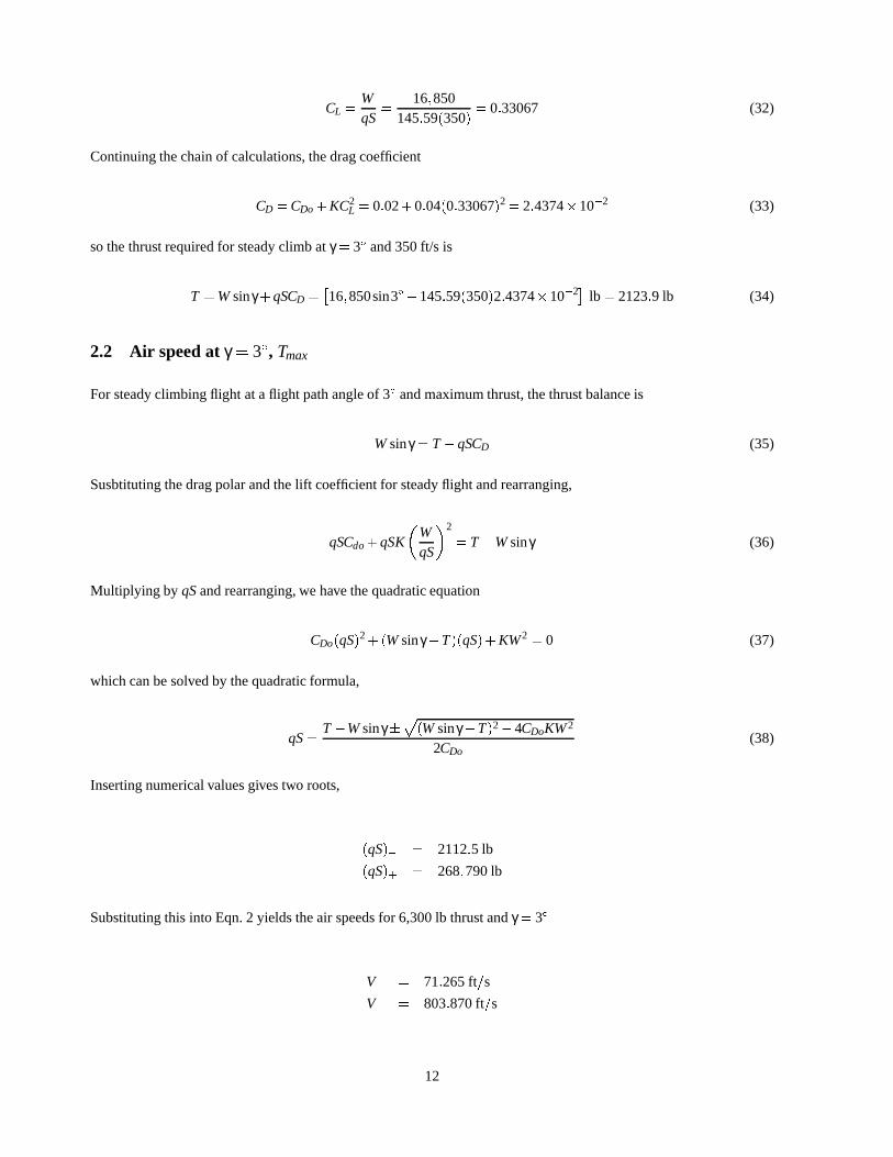
CL =WqS
=16;850
145:59(350)= 0:33067 (32)
Continuing the chain of calculations, the drag coefficient
CD =CDo+KC2L = 0:02+0:04(0:33067)2= 2:4374�10�2 (33)
so the thrust required for steady climb atγ = 3� and 350 ft/s is
T =Wsinγ+qSCD =�16;850sin3�+145:59(350)2:4374�10�2� lb = 2123:9 lb (34)
2.2 Air speed atγ= 3�, Tmax
For steady climbing flight at a flight path angle of 3� and maximum thrust, the thrust balance is
Wsinγ = T�qSCD (35)
Susbtituting the drag polar and the lift coefficient for steady flight and rearranging,
qSCdo+qSK
�WqS
�2
= T�Wsinγ (36)
Multiplying by qSand rearranging, we have the quadratic equation
CDo(qS)2+(Wsinγ�T)(qS)+KW2 = 0 (37)
which can be solved by the quadratic formula,
qS=T�Wsinγ�
p(Wsinγ�T)2�4CDoKW2
2CDo(38)
Inserting numerical values gives two roots,
(qS)� = 2112:5 lb
(qS)+ = 268;790 lb
Substituting this into Eqn. 2 yields the air speeds for 6,300 lb thrust andγ = 3�
V� = 71:265 ft=s
V+ = 803:870 ft=s
12

2.3 Minimum thrust for 10 ft/s climb rate
At a constant rate of climbRC=V sinγ = 10 ft/s, the thrust balance
sinγ =RCV
=T�D
W(39)
Rearranging and expanding the drag term,
T =RCV
W+qSCDo+KC2L (40)
which has minima at
∂T∂V
=�RCV
WV
+SCD∂q∂V
+2qSKCL∂CL
∂V= 0 (41)
Substituting in the derivatives of Eqn. 11 and Eqn. 12,
∂T∂V
=�RCV
WV
+2qSV
CD�4qSV
KC2L = 0 (42)
If there’s an analytical solution to this, it’s beyond my patience. Instead, the following IDL code returns Fig. 4, a plotof ∂T=∂V as a function of air speed, while a secant-method root-finding routine finds that the minimum thrust for a 10ft/s climb rate is at
V = 279:63 ft=s
T = 1602:3 lb
pro hw4_2c
; Define initial conditions & conversions.
rho = 2.3769e-3 ; sea level density, slug/ftˆ3W = 16850. ; aircraft weight, lbS = 350. ; wing area, ftˆ2T_a = 6300. ; engine shaft power, hpC_do = 0.02 ; parasitic drag coefficientK = 0.04 ; induced drag factor, 1/pi e ARRC = 10. ; rate of climb, ft/s
; Create air speed array.
v_min = 200. ; minimum speed, ft/sv_max = 300. ; maximum speed, ft/sbins = fix(v_max - v_min) + 1 ; number of array binsV = v_min + findgen(bins) ; air speed, ft/s
; Calculate slope of thrust curve, dT/dV.
13

200 220 240 260 280 300airspeed V (ft/s)
-8
-6
-4
-2
0
2
dT/d
V (
lb-s
/ft)
Figure 4: Thrust slope∂T=∂V for steady 10 ft/s climb rate.
q = rho * Vˆ2/2 ; dynamic pressure, psfC_l = W/(q*S) ; lift coefficientC_d = C_do + K*C_lˆ2 ; drag coefficient
dTdV = - RC*W/Vˆ2 + (2*q*S*C_d)/V - (4*q*S*K*C_lˆ2)/V
; Plot dT/dV as a function of airspeed for minimum-finding.
xtitle = ’airspeed V (ft/s)’ ; x-axis titleytitle = ’dT/dV (lb-s/ft)’ ; y-axis titlefile = ’fig4_2c.eps’ ; file namescale = 1.0xsz = 4.0*scaleysz = 3.0*scale
set_plot, ’ps’ ; set plot device to PostScriptdevice,/encapsulated,/preview,filename=file ; open file & save EPSdevice,/inches, xsize=xsz, ysize=ysz, $
font_size = 7plot, V, dTdV, xtitle=xtitle, $
ytitle=ytitle, font=0device, /close ; close the file
end
14

2.4 Maximum flight path angle
The thrust at altitude is a function of density (Anderson, 3rd ed., Example 6.4),
T = Toρρo
(43)
The flight path angle at a given thrustT is (for smallγ)
γ =T�qSCD
W(44)
At a constant altitude (soT is constant), this has a maximum at
∂γ∂V
=� SW
�CD
∂q∂V
+qK∂C2
L
∂V
�= 0 (45)
Substituting in the derivatives of Eqn. 11 and Eqn. 12,
∂γ∂V
=� 2qSWV
(CD�2KC2L) (46)
The only nontrivial solution is at
CD =CDo+KC2L = 2KC2
L (47)
Solving for lift coefficient at maximum climb,
C�
L =Wq�S
=
rCDo
K(48)
so the dynamic pressure
q� =WS
rK
CDo(49)
and the airspeed at maximum flight path angle
V� =
s2WρS
rK
CDo(50)
This airspeed and the resulting thrust are plotted in Fig. 5 as a function of altitude by the following IDL code:
pro hw4_2d
; Define fundamental constants & conversions.
15

0 5 10 15 20altitude (1000 ft)
240
260
280
300
320
airs
peed
V*
(ft/s
)
0 5 10 15 20altitude (1000 ft)
10
12
14
16
18
fligh
t pat
h an
gle
(deg
)
Figure 5: Maximum flight path angle and airspeed at max climb angle as a function of altitude.
R = 1716. ; air gas constant, ft-lb/slug-RT_z = 459.67 ; 0 F in Rg_o = 32.174 ; std gee, ft/sˆ2km2ft = 3280.8 ; 1 km in ftm2ft = km2ft/1000. ; 1 m in ftK2R = 1.8 ; 1 K in Rhp = 550. ; 1 hp in ft-lb/s
; Define initial conditions.
p_sl = 2116.2 ; sea level pressure, lb/ftˆ2T_sl = 518.69 ; sea level temperature, Rrho_sl = 2.3769e-3 ; sea level density, slug/ftˆ3a_1 = -6.5e-3*K2R/m2ft ; lapse rate, R/ftW = 16850. ; aircraft weight, lb
16

S = 350. ; wing area, ftˆ2T_o = 6300. ; engine thrust, lbC_do = 0.02 ; parasitic drag coefficientK = 0.04 ; induced drag factor, 1/pi e AR
; Create gradient layer altitude, temperature, pressure & density arrays.
bins = 201. ; number of array binsh = 100.*findgen(bins) ; altitude in gradient layer, ftT = T_sl + a_1*h ; temperature in gradient layer, Rp = p_sl*(T/T_sl)ˆ(-g_o/(a_1*R)) ; pressure in gradient layer, lb/ftˆ2rho = p/(R*T) ; density in gradient layer, slug/ftˆ3
; Calculate and plot air speed for max steady climb as function of altitude.
r1 = sqrt(K/C_do)r2 = (2.*W)/(rho*S)V_star = sqrt(r1*r2) ; max climb air speed, ft/sq_star = W*r1/S ; max climb dynamic pressure, lb/ftˆ2
xtitle = ’altitude (1000 ft)’ ; x-axis titleytitle = ’airspeed V* (ft/s)’ ; y-axis titlefile = ’fig4_2dv.eps’ ; file namescale = 1.0xsz = 4.0*scaleysz = 3.0*scale
set_plot, ’ps’ ; set plot device to PostScriptdevice,/encapsulated,/preview,filename=file ; open file & save EPSdevice,/inches, xsize=xsz, ysize=ysz, $
font_size = 7plot, h/1000., V_star, xtitle=xtitle, $
ytitle=ytitle, font=0, $xstyle = 1, ystyle = 1
device, /close ; close the file
; Calculate and plot required power, available power and maximum rate of climb.
C_L = W/(q_star*S) ; max climb lift coefficientC_D = C_do + K*C_Lˆ2 ; max climb drag coefficientD = q_star*S*C_D ; drag, lbT_a = (rho/rho_sl)*T_o ; available thrust, lbgamma = (T_a - D)*!radeg/W ; max flight path angle, deg
ytitle = ’flight path angle (deg)’ ; y-axis titlefile = ’fig4_2dr.eps’ ; file namescale = 1.0xsz = 4.0*scaleysz = 3.0*scale
set_plot, ’ps’ ; set plot device to PostScriptdevice,/encapsulated,/preview,filename=file ; open file & save EPSdevice,/inches, xsize=xsz, ysize=ysz, $
font_size = 7plot, h/1000., gamma, xtitle=xtitle, $
17

ytitle=ytitle, font=0, $xstyle = 1, ystyle = 1
device, /close ; close the file
end
2.5 Minimum glide angle
As shown in section 1.5, the minimum glide angle
γg;min = 2p
KCDo = 2p
0:04(0:02) = 5:657�10�2 rad= 3:241� (51)
is not a function of altitude, but the velocity at minimum glide angle
Vg;min =
s2WρS
rK
CDo(52)
is, as shown in Fig. 6.
pro hw4_2e
; Define fundamental constants & conversions.
R = 1716. ; air gas constant, ft-lb/slug-RT_z = 459.67 ; 0 F in Rg_o = 32.174 ; std gee, ft/sˆ2km2ft = 3280.8 ; 1 km in ftm2ft = km2ft/1000. ; 1 m in ftK2R = 1.8 ; 1 K in R
; Define initial conditions.
p_sl = 2116.2 ; sea level pressure, lb/ftˆ2T_sl = 518.69 ; sea level temperature, Rrho_sl = 2.3769e-3 ; sea level density, slug/ftˆ3a_1 = -6.5e-3*K2R/m2ft ; lapse rate, R/ftW = 16850. ; aircraft weight, lbS = 350. ; wing area, ftˆ2C_do = 0.02 ; parasitic drag coefficientK_D = 0.04 ; induced drag factor, 1/pi e AR
; Create gradient layer altitude, temperature, pressure & density arrays.
bins = 201. ; number of array binsh = 100.*findgen(bins) ; altitude in gradient layer, ftT = T_sl + a_1*h ; temperature in gradient layer, Rp = p_sl*(T/T_sl)ˆ(-g_o/(a_1*R)) ; pressure in gradient layer, lb/ftˆ2rho = p/(R*T) ; density in gradient layer, slug/ftˆ3
18

0 5 10 15 20altitude (1000 ft)
240
260
280
300
320
airs
peed
V (
ft/s)
0 5 10 15 20altitude (1000 ft)
3.0
3.5
4.0
4.5
5.0
rate
of c
limb
(ft/s
)
Figure 6: Minimum glide angle and airspeed at minimum glide angle as a function of altitude.
; Calculate and plot air speed for min steady glide as function of altitude.
q = (W/S)*sqrt(K_D/C_do) ; min glide dynamic pressure, lb/ftˆ2V = sqrt(2*q/rho) ; min glide air speed, ft/s
xtitle = ’altitude (1000 ft)’ ; x-axis titleytitle = ’airspeed V (ft/s)’ ; y-axis titlefile = ’fig4_2ev.eps’ ; file namescale = 1.0xsz = 4.0*scaleysz = 3.0*scale
set_plot, ’ps’ ; set plot device to PostScriptdevice,/encapsulated,/preview,filename=file ; open file & save EPSdevice,/inches, xsize=xsz, ysize=ysz, $
19
font_size = 7plot, h/1000., V, xtitle=xtitle, $
ytitle=ytitle, font=0, $xstyle = 1, ystyle = 1
device, /close ; close the file
; Calculate and plot minimum glide angle as a function of altitude.
gamma = 2*sqrt(K_D*C_do)*(fltarr(bins) + 1) ; glide angle, radiansgamma = gamma*!radeg ; convert to degrees
ytitle = ’rate of climb (ft/s)’ ; y-axis titlefile = ’fig4_2eg.eps’ ; file namescale = 1.0xsz = 4.0*scaleysz = 3.0*scale
set_plot, ’ps’ ; set plot device to PostScriptdevice,/encapsulated,/preview,filename=file ; open file & save EPSdevice,/inches, xsize=xsz, ysize=ysz, $
font_size = 7plot, h/1000., gamma, xtitle=xtitle, $
ytitle=ytitle, font=0, $yrange=[3.,5.] ; force plot y-range
device, /close ; close the file
end
3 Problem 3
Assume that an aircraft has weight of 5600 lbs and wing surface area of 330 ft2. The maximum power available fromthe engine propulsion system at sea level is
Pa = 122:2+0:556V (53)
and the power required for steady level flight at sea level is
Pr = 357:8�2:4375V+0:005625V2 (54)
where power is in hp and air speed is in ft/s. The lift coefficient is
CL = 0:16α�0:00533α2 (55)
where angle of attack is in degrees, this expression is valid up to stall.
1. Develop graphical plots for the maximum power and thrust available from the engine propulsion system and thepower and thrust required for steady level flight as functions of the air speed. Assume sea level flight.
20

2. If the aircraft engine delivers 300 hp, what is the air speed (or air speeds) for which the aircraft maintains steadylevel flight at sea level? What is the required throttle as a percentage of the maximum power available? What isthe required angle of attack?
3. If the aircraft engine delivers a constant 500 lbs of thrust, what is the air speed (or speeds) of the aircraft forwhich steady level flight is maintained at sea level? What is the required throttle as a percentage of the maximumthrust available? What is the required angle of attack?
4. What are the power level and the thrust level required to maintain steady level flight at an air speed of 350 ft/s atsea level? What is the required throttle as a percentage of the maximum power available? What is the requiredvalue of the angle of attack?
5. What is the maximum air speed that can be maintained in steady level flight at sea level? What are the requiredpower level and the required thrust level? What is the required throttle as a percentage of the maximum poweravailable? What is the required value of the angle of attack?
6. What is the minimum air speed that can be maintained in steady level flight at sea level? What are the requiredpower level and the required thrust level? What is the required throttle as a percentage of the maximum poweravailable? What is the required value of the angle of attack?
7. What is the maximum rate of climb that can be maintained at sea level? What are the required power level andthe required thrust level? What are the required values of the air speed and of the angle of attack?
8. What is the minimal glide slope angle at sea level, assuming the engine is turned off? What are the requiredvalues of the air speed and of the angle of attack?
3.1 Available and required thrust and power
This simply entails plotting Eqns. 53 and 54 for power, and using the relation
T = P=V (56)
for thrust. Figure 7 shows these plots.
3.2 Air speed atPd = 300hp
Given a delivered power ofPd = 300 hp, possible air speeds lie at the roots of
300 hp= (357:8�2:4375u+0:005625u2) hp (57)
whereu�V=Vo is a nondimensionalization (Vo = 1 ft/s) that lets us avoid confusion about what our dimensions are.Rearranging and solving by the quadratic formula gives
V� = 25:179 ft=s
V+ = 408:16 ft=s
which is confirmed by a glance at Fig. 7. The available power at these airspeeds is
21

0 100 200 300 400 500airspeed (ft/s)
0
200
400
600
800
1000
1200fo
rce
(lb)
0 100 200 300 400 500airspeed (ft/s)
0
100
200
300
400
500
600
pow
er (
hp)
Figure 7: Required (solid line) and available (dotted line) thrust and power as a function of air speed.
22
P� = (122:2+0:556[25:179]) hp= 136:20 hp
P+ = (122:2+0:556[408:16]) hp= 349:14 hp
so the percent power throttleθp;� = Pd=P� is
θp;� =300
136:20= 220:27%
θp;+ =300
349:14= 85:925%
To find the possible angle of attack, start by calculating dynamic pressures
q� =12(2:3769�10�3)(25:179)2 lb
ft2 = 0:75346lbft2
q+ =12(2:3769�10�3)(408:16)2 lb
ft2 = 197:99lbft2
and lift coefficients
CL� =5600
0:75346(330)= 22:522
CL+ =5600
197:99(330)= 8:5710�10�2
corresponding to the possible airspeeds. Substituting into Eqn. 55,
0 = 0:00533α2��0:16α�+22:522
0 = 0:00533α2+�0:16α++8:5710�10�2
The low-speed solution has no real roots,
α� = (15:009�63:248p�1)� (58)
while the high-speed solution has two real roots,
α+;1 = 0:5450�
α+;2 = 29:473�
The lower angle of attack at high speed is more physically reasonable, as 29.473� is well beyond stall for most airfoils,but both are allowed by the given mathematical model.
23

3.3 Air speed atTd = 500 lb
Given a delivered thrust ofTd = 500 hp, possible air speeds lie at the roots of
500V lb = (357:8�2:4375u+0:005625u2) hp (59)
Dividing through byVo = 1 ft/s and using the identity 550 ft-lb/s = 1 hp, this becomes
500u= 196;790�1340:6u+3:0938u2 (60)
Solving this by the quadratic formula gives the air speeds
V� = 139:75 ft=s
V+ = 455:21 ft=s
which is confirmed by a glance at Fig. 7. The available thrust at these airspeeds is
T� =550
139:75(122:2+0:556[139:75]) lb = 786:73 hp
T+ =550
455:21(122:2+0:556[455:21]) hp= 453:45 hp
so the percent thrust throttleθt;� = Td=T� is
θt;� =500
786:73= 63:554%
θt;+ =500
453:45= 110:27%
To find the possible angle of attack, start by calculating dynamic pressures
q� =12(2:3769�10�3)(139:75)2 lb
ft2 = 23:211lbft2
q+ =12(2:3769�10�3)(455:21)2 lb
ft2 = 246:27lbft2
and lift coefficients
CL� =5600
23:211(330)= 0:73111
CL+ =5600
246:27(330)= 6:8907�10�2
24

corresponding to the possible airspeeds. Substituting into Eqn. 55,
0 = 0:00533α2��0:16α�+0:73111
0 = 0:00533α2+�0:16α++6:8907�10�2
The low-speed solution has roots at
α�;1 = 5:6220�
α�;2 = 24:396�
while the high-speed solution has two real roots,
α+;1 = 0:43700�
α+;2 = 29:581�
Again, all 4 angles are allowed by the given mathematical model.
3.4 Power and thrust for 350 ft/s air speed
At V = 350 ft/s, the required power
Pr = (357:8�2:4375[350]+0:005625[350]2) hp= 193:75 hp (61)
so the required thrust
Tr =Pr
V=
193:75 hp350 ft=s
�550 ft� lb1 hp�s
�= 304:44 lb (62)
The available power atV = 350 ft/s is
Pa = (122:2+0:556[350]) hp= 316:80 hp (63)
so the percent power throttle is
θp =193:75316:80
= 61:155% (64)
A glance at Fig. 7 confirms these values. The dynamic pressure is
q=12(2:3769�10�3)(350)2 lb
ft2 = 145:59lbft2 (65)
25

while substituting the lift coefficient
CL =5600
145:59(330)= 0:11656 (66)
into Eqn. 55,
0= 0:00533α2��0:16α�+0:11656 (67)
gives the roots
α1 = 0:74666�
α2 = 29:271�
3.5 Maximum air speed
In steady level flight, maximum air speed is at the upper root ofPa = Pr :
(122:2+0:556u) hp= (357:8�2:4375u+0:005625u2) hp (68)
Combining terms and cancelling units,
0= 235:6�2:9935u+5:625�10�3u2 (69)
which has roots at
V� = 96:04 ft=s
V+ = 436:14 ft=s
Thus, the maximum air speedVmax= 436:14 ft/s; the required throttle is, of course, 100%. The dynamic pressure atVmax is
q=12(2:3769�10�3)(436:14)2 lb
ft2 = 226:06lbft2 (70)
so the lift coefficient
CL =5600
226:06(330)= 7:5066�10�2 (71)
Substituting this into Eqn. 55,
0= 0:00533α2��0:16α�+7:5066�10�2 (72)
26

gives the roots
α1 = 0:47630�
α2 = 29:524�
3.6 Minimum air speed
As shown in the last section,V� = 96:04 ft/s is the lower intersection of the required and available power curves. Thedynamic pressure atVmin is
q=12(2:3769�10�3)(96:04)2 lb
ft2 = 10:962lbft2 (73)
so the lift coefficient
CL =5600
10:962(330)= 1:5481 (74)
Substituting this into Eqn. 55,
0= 0:00533α2��0:16α�+1:5481�10�2 (75)
gives the complex roots
α� = (15:009�8:0727p�1)� (76)
In physical terms, this means that the airfoil is incapable of reaching a high enoughCL to support steady level flight atV�. TheCL curve has a maximum at
∂CL
∂α= 0:16�0:01066α= 0 (77)
soαmax= 15:009�, giving a maximum lift coefficient
CLmax= 0:16(15:009)�0:00533(15:009)2= 1:2007 (78)
The minimum dynamic pressure
qmax=W
SCLmax=
56001:2007(330)
lbft2 = 14:133
lbft2 (79)
yielding a minimum air speed
Vmin =
s2qρ
=
r2(14:133)
2:3769�10�3
fts= 109:05
fts
(80)
27

The required power at minimum air speed
Pr = (357:8�2:4375[109:05]+0:005625[109:05]2) hp= 158:88 hp (81)
while the available power
Pa = (122:2+0:556[109:05]) hp= 182:83 hp (82)
so the percent power throttle is
θp =158:88182:83
= 86:900% (83)
3.7 Maximum rate of climb
The rate of climb has a maximum where
∂RC∂V
=1W
�∂Pa
∂V� ∂Pr
∂V
�= 0 (84)
Rearranging and taking the two derivatives, the nontrivial solution is at
0:566=�2:4375+1:125�10�2V (85)
Solving, the air speed at maximum rate of climb
VRCmax=0:566+2:43751:125�10�2
fts= 266:98
fts
(86)
The available power
Pa = (122:2+0:556[266:98]) hp= 270:64 hp (87)
while the required power
Pr = (357:8�2:4375[266:98]+0:005625[266:98]2) hp= 107:98 hp (88)
so that the maximum rate of climb
RCmax=(270:15�107:98) hp
5600 lb
�550 ft� lb1 hp�s
�= 15:928
fts
(89)
To find angle of attack, start with dynamic pressure
28

q=12(2:3769�10�3)(266:98)2 lb
ft2 = 84:711lbft2 (90)
so the lift coefficient
CL =5600
84:711(330)= 0:20033 (91)
Substituting this into Eqn. 55,
0= 0:00533α2��0:16α�+0:20167 (92)
gives the possible angles of attack at maximum climb
α1 = 1:3087�
α2 = 28:709�
3.8 Minimum glide angle
The glide slope (for smallγg)
γg =DW
=Pr
WV(93)
has a minimum when
∂γg
∂V=
1W
∂∂V
�Pr
V
�=
1W
�1V
∂Pr
∂V� Pr
V2
�= 0 (94)
The only nontrivial solution is at
1V
∂Pr
∂V=
Pr
V2 (95)
Multiplying by V2 and expandingPr ,
V(�2:4375+1:1250�10�2V) = (357:8�2:4375V+5:625�10�3V2) (96)
Regrouping, we have
0= 357:8�5:625�10�3V2 (97)
so the air speed at minimum glide angle
29

Vmin =
r357:8
5:625�10�3
fts= 252:21
fts
(98)
The required power at minimum glide angle is
Pr = (357:8�2:4375[252:21]+0:005625[252:21]2) hp= 100:84 hp (99)
so that minimum drag is
Dmin =Pr
Vmin=
100:84 hp�s252:21 ft
�550 ft� lb1 hp�s
�= 219:90 lb (100)
and minimum glide slope
γgmin =219:90 lb5600 lb
= 3:9268�10�2 rad= 2:2499� (101)
As ever, to find angle of attack we start with dynamic pressure
q=12(2:3769�10�3)(252:21)2 lb
ft2 = 75:597lbft2 (102)
so the lift coefficient
CL =5600
75:597(330)= 0:22448 (103)
Substituting this into Eqn. 55,
0= 0:00533α2��0:16α�+0:22448 (104)
gives the possible angles of attack at maximum climb
α1 = 1:4751�
α2 = 28:534�
and we’re done. (Whew!)
30