
ADVISORY COMMITTEE on ARTIFICIAL LIMBS - … · contributed the present lightweight plastic...
73
Transcript of ADVISORY COMMITTEE on ARTIFICIAL LIMBS - … · contributed the present lightweight plastic...


ADVISORY COMMITTEE on ARTIFICIAL LIMBS Division of Engineering and Industrial Research
NATIONAL ACADEMY OF SCIENCES—NATIONAL RESEARCH COUNQL
Paul E. Klopsteg, Chairman
Rufus H. Alldredge Howard D. Eberhart Robert R. McMath C. Leslie Mitchell Craig L. Taylor T. Campbell Thompson Philip D. Wilson
PROFESSIONAL ASSOCIATES Robert S. Allen Verne T. Inman
E X E C U T I V E D I R E C T O R F. S. Strong, Jr.
E X E C U T I V E S E C R E T A R Y A. Bennett Wilson, Jr.
S T A F F E D I T O R Bryson Fleer
Artificial Limbs
VOL. 2 SEPTEMBER 1 9 5 5 N O . 3
CONTENTS
HARNESSING—HERE AND HEREAFTER
John Lyman 1
THE BIOMECHANICS OF CONTROL IN UPPER-EXTREMITY PROSTHESES
Craig L. Taylor 4
HARNESS PATTERNS FOR UPPER-EXTREMITY PROSTHESES
Robert J. Pursley 26
SOME EXPERIENCE IN HARNESSING EXTREME ARM CASES
Craig L. Taylor 61
DIGEST OF MAJOR ACTIVITIES OF THE ARTIFICIAL LIMB PROGRAM . 64
A D V I S O R Y C O M M I T T E E o n A R T I F I C I A L LIMBS
NATIONAL ACADEMY OF SCIENCES—NATIONAL RESEARCH COUNCIL
2101 Constitution Ave. Washington 25, D. C.

Artificial Limbs is a publication of the Advisory Committee on Artificial Limbs, National Academy of Sciences—National Research Council, issued three times a year, in January, May, and September, in partial fulfillment of Veterans Administration Contract VAm-21223. Copyright 1956 by the National Academy of Sciences—National Research Council. Quoting and reprinting are freely permitted, providing appropriate credit is given. The opinions expressed by contributors are their own and are not necessarily those of the Advisory Committee on Artificial Limbs. Library of Congress Catalog Card No. 55-7710.
Editorial Board: F. S. Strong, Jr., A. Bennett Wilson, Jr., Bryson Fleer
Harnessing—Here and Hereafter JOHN LYMAN, Ph.D.1
1 Assistant Professor of Engineering, University of California, Los Angeles.
However well designed the other parts of an artificial arm may be, the functional success of the upper-extremity prosthesis must ultimately depend upon the adequacy of the coupling between the human being and the inanimate mechanism. Since this man-machine linkage is intended to hold the arm on the stump and to secure from residual body sources the mechanical power necessary for operation and control of the prosthesis, the technique of constructing it has come to be known simply as "harnessing." Because body harness is such ah intimate piece of apparel, and because arm amputees exhibit the same kinds of individual differences as characterize the rest of the population, it seems likely that proper harnessing will long remain a tribute to the personal skill of the prosthetist, despite all advances in prefabricated components. Although the clinic team may prescribe the specifications for a prosthesis within the existing framework of medical and engineering knowledge, the final result depends largely upon the prosthetist's talent for constructing and fitting the harness in such a way as to meet anatomical, physiological, and functional requirements.
Functionally, the harness may serve one or more of three purposes: it may hold the prosthesis in place; it may transmit power and excursion to produce force and movement in operating components; it may convey to the wearer the intelligence needed for arm control. In conventional construction of upper-extremity prostheses, it has been customary to rely upon the harness for the performance of all three of these services and, further, to obtain them all from a single harness system. Such an arrangement is of course grossly unlike that of the normal limb, where the control function, mediated by the nervous system, is clearly separated from the functions of suspension and of power transmission. Only in externally powered prostheses, as for examples the TBM Electric Arm and the Vaduz hand, has an attempt been made to separate the control function from the power and suspensory functions. Although to date such devices have not proved to be as useful or reliable as simpler ones, they are representative of an approach which may, in the long run, lead to far more refined limb substi-
1

tutes than can be contemplated by further development of a harnessing philosophy which stresses the combining of suspension, power transmission, and control.
The use of body power for operating an artificial arm forms an inherent control link between the neuromuscular system and the prosthesis. To the extent that a "closed loop" is effected via the sensory feedback available to the power-producing muscles, control of force and excursion through the power-transmission system is possible without the aid of external sensory-feedback loops such as vision and hearing. While the latter cues are generally present, they can at best serve only in an auxiliary capacity. The rich sensations of touch, pressure, pain, and temperature, which have been lost with the natural limb, have no substitute beyond their dim reflection in the signals from harness strap or cineplasty muscle pin of present-day prosthetics technology.
One can argue, with considerable sustaining evidence, that the modern arm prosthesis is quite functionally adequate in most respects and that the addition of refinements in the form of further sensory cues for improved control would only complicate harnessing unnecessarily. But to take this viewpoint is paying tribute to the adaptability of the human mechanism rather than to the adequacy of today's prosthetics research and development. As facts currently stand, it appears that no clear-cut assessment has been made of the importance of sensory losses to the amputee. The effort has been to achieve prosthetic replacement of motor function, and it still is not generally recognized that this goal has been approached with the present degree of success only because sensory control loops are established incidentally in the course of harnessing for power transmission. The major inadequacies leading to failure in externally powered prostheses can be traced directly to shortcomings in the design of control loops—loops which are intrinsic even in the crudest of body-powered prostheses.
Since in the present state of the art the optimum connection between the amputee and the operating mechanism is still so indispensable to the proper functioning of the upper-extremity prosthesis, this issue of ARTIFICIAL LIMBS is devoted to a summary of current harnessing technology as developed under the auspices of the Advisory Committee on Artificial Limbs. Although progress in the improvement of body harness has been substantial since World War II, even the latest techniques fall far short of duplicating the neuromuscular mechanism of the normal arm. And consequently there is still a great deal of forward-looking to be done in the research, development, and production phases of upper-extremity prosthetics.
Where will the technology come from that may make possible "sensory prostheses" with attendant refinements in the present "motor prostheses"? Probably not directly from current trends in artificial-limb research. As is common knowledge, a very real and dynamic revolution is under way in the modern engineering sciences. It is accompanied by a plethora of popular terms like
2

"cybernetics," "servomechanisms," "information theory," "digital and analogue computers," and "automation," to name a few. From the developments that are taking place, many new materials and processes are becoming available. Just as the aircraft industry, through the Northrop design studies, has contributed the present lightweight plastic artificial arm and the Bowden-cable transmission system, so it may be anticipated that within a relatively few years the electronics and missile industries may make even greater contributions. Compact, reliable, and lightweight items like the famed transistor may become as commonplace in the control systems for artificial arms as is presently the case in hearing aids. New products from metallurgy and chemistry may eventually make it possible to realize direct attachment of prosthetic devices to remaining skeletal members of the body through the skin and surrounding tissue, with consequent elimination of the socket and of the suspensory elements of harness. Much of the theory and much of the methodology for accomplishing the direct coupling of man to mechanism, including the all-important link to the nervous system for control, are either available already or else are promised within the foreseeable future.
Because in the field of amputee rehabilitation there are never apt to be available the amounts of research money now characteristic of other fields of science and invention, it is fortunate that a systematic plan for the advancement of limb prosthetics has become so well established in the decade since World War II. The Artificial Limb Program furnishes an organized means of following progress in other areas and of adapting to limb substitutes new approaches and new techniques that would otherwise lie far beyond the purse of prosthetics research itself. The future in design of limb replacements is thus perhaps now greater than ever before. Even so, no matter how sophisticated upper-extremity prostheses may become, the actual utility of any given artificial arm will continue to reside largely in the degree to which the fitter can attain the optimum sensory-motor association through accomplished harnessmaking. In no other known way can so much satisfaction be afforded the individual arm amputee.
3

The Biomechanics of Control in Upper-Extremity Prostheses
CRAIG L. TAYLOR, Ph.D.1
1 Professor of Engineering, University of California, Los Angeles; member, Advisory Committee on Artificial Limbs, National Research Council, and of the Technical Committee on Prosthetics, ACAL, NRC.
In the rehabilitation of the upper-extremity amputee, structural replacement by prosthetic arm and hand is an obvious requirement, and it poses a comparatively easy task; functional replacement by remote control and by substitute mechanical apparatus is more elusive and hence infinitely harder. For the purposes of functional utility, remaining movements of upper arm, shoulder, and torso must be harnessed, and use must be made of a variety of mechanical devices which amplify remaining resources by alternators, springs, locks, and switching arrangements. The facility of control attained through this apparatus is the key to its ultimate value.
The future of upper-extremity prosthetics depends upon an ever-increasing understanding of the mechanics of the human body by all who minister to the amputee—prosthetist, surgeon, and therapist alike. It must always be stressed that the final goal is an amputee who can function. Too often there is a tendency to put undue faith in the marvels of mechanism alone, when in fact it is the man-machine combination that determines performance. It is in this broad frame of reference that the biomechanical basis of upper-extremity control must be approached.
PROSTHETICS ANTHROPOMETRY
SURFACE LANDMARKS
If successful control is to be obtained, the various components of the prosthesis must be positioned with a good degree of accuracy.
To do so requires reference points on the body, of which the most satisfactory are certain bony landmarks. Most of these skeletal prominences protrude to such an extent that location is easily possible by eye. Others require palpation, and this method should be used to verify observation in every case. The bones most concerned in upper-extremity anthropometry are the clavicle, the scapula, the humerus, the ulna, and the seventh cervical vertebra. Surface indications of protuberances, angles, or other features of these bones constitute the landmarks, the locations and definitions being given in Figure 1.
ARM AND TRUNK MEASUREMENTS
2 In everyday language the word "arm" is of course taken to mean the entire upper extremity, or at least that portion between shoulder and wrist. In anatomical terms, "arm" is reserved specifically for the segment between shoulder and elbow, that between elbow and wrist being the "forearm." Although in the lower extremity the word "leg" commonly means the entire lower limb, whereas anatomically the "leg" is that segment between knee and ankle, confusion is easily avoided because we have the special word "shank." No such spare word is available to describe the humeral segment of the upper limb.—ED.
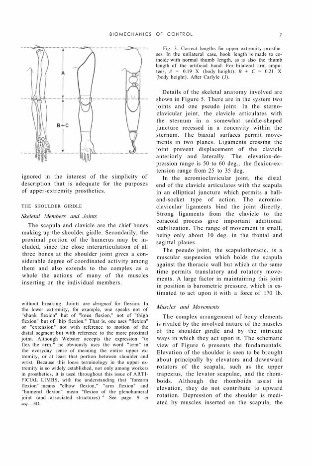
The typical male torso and upper extremity are shown in Figure 2, which, together with Table 1, was derived from average measurements on Army personnel (16). Such an average form serves to establish harness patterns and control paths. The arm, forearm, and epicondyle-thumb lengths 2 constitute the basis of sizing prostheses (2). Arm length places the artificial elbow; forearm length locates the terminal device. The epicondyle-thumb length is an important over-all sizing reference because in the unilateral arm am-
4

putee it is customary to match hook length (and, in the case of the artificial hand, thumb length) to the length of the natural thumb (Fig. 3). The bilateral arm amputee can be sized from body height by means of the Carlyle formulas (3), which employ factors derived from average body proportions.
Fig. 1. Bones and external landmarks in the upper extremity. Definitions: seventh cervical vertebra, most prominent vertebra in the neck region; acromion, extreme lateral edge of the bony shelf of the shoulder; inferior angle of scapula, lowest point on shoulder blade; epicondyles, lateral and medial bony points at the pivot of the elbow; ulnar styloid, projecting point on little-finger side of the wrist.
FUNCTIONAL ANATOMY
The human torso, shoulder, and upper extremity are exceedingly complex structures. In any dealing with these elements of anatomy, therefore, it is desirable to sort out from the mass of detail those features important to the particular area of study and application. Where prosthetic controls are concerned, the mechanism of movement is the central subject of consideration. This functional anatomy treats of the aspects of bone, joint, and muscle structure that together determine the modes and ranges of motion of the parts. It is a descriptive science, and while to escape dependence upon nomenclature is therefore impossible, the purpose here is to convey a basic understanding of the operation of the upper-extremity mechanisms without undue use of specialized terminology. In any case, the reader should have available basic anatomical references such as Gray's Anatomy (13) or kinesiology texts such as those of Steindler (17) and of Hollinshead (9).
ELEMENTARY MOTIONS OF THE UPPER EXTREMITY The geometry of each joint is complex, and
most movements involve an interaction of two
or more joints. Consequently, a motion nomenclature based on joint movements would be unnecessarily complicated. More simply, the motion of each part upon its proximal joint may be described with respect to the principal planes which intersect at that joint. In this system, moreover, one may define a standard position in which the trunk is erect, the arms hang with their axes vertical, the elbows are flexed to 90 deg., and the wrist planes are vertical to assume the "shake-hands" position.
Figure 4 presents the angular movements possible in the three planes of space. The shoulder-on-chest, arm-on-shoulder, and hand-on-wrist actions take place through two angles, as if moving about a universal joint. Geometrically, the arm motions are more precisely defined by a spherical coordinate system where the segment position is given by longitude and
B I O M E C H A N I C S OF CONTROL 5

colatitude angles. For descriptive purposes, however, the anatomical nomenclature is commonly used. It should be recognized that, for multiaxial joints, flexion-extension and elevation-depression angles describe motions in the major orthogonal planes only, and intermediate angular excursions must be thought of as combinations of these motions.
Fig. 2. Basic anthropometry of the male torso and upper extremity. See Table 1.
The simplified movement system depicted in Figure 4 is incomplete in many ways. Not included are such movements as twisting of the shoulder due to various scapular movements, anterior-posterior swings of the arm in positions of partial elevation, and the slightly conical surface of revolution of forearm flexion.3 These details may, however, be
3 It deserves to be noted here that, taken literally, expressions such as "forearm flexion-extension," "arm flexion-extension," and "humeral flexion-extension" represent questionable nomenclature. To "flex" means to "bend." Limb segments do not bend very readily
6 T A Y L O R
without breaking. Joints are designed for flexion. In the lower extremity, for example, one speaks not of "shank flexion" but of "knee flexion," not of "thigh flexion" but of "hip flexion." That is, one uses "flexion" or "extension" not with reference to motion of the distal segment but with reference to the more proximal joint. Although Webster accepts the expression "to flex the arm," he obviously uses the word "arm" in the everyday sense of meaning the entire upper extremity, or at least that portion between shoulder and wrist. Because this loose terminology in the upper extremity is so widely established, not only among workers in prosthetics, it is used throughout this issue of ARTIFICIAL LIMBS, with the understanding that "forearm flexion" means "elbow flexion," "arm flexion" and "humeral flexion" mean "flexion of the glenohumeral joint (and associated structures) " See page 9 et seq.—ED.
ignored in the interest of the simplicity of description that is adequate for the purposes of upper-extremity prosthetics.
Fig. 3. Correct lengths for upper-extremity prostheses. In the unilateral case, hook length is made to coincide with normal thumb length, as is also the thumb length of the artificial hand. For bilateral arm amputees, A = 0.19 X (body height); B + C = 0.21 X (body height). After Carlyle (J).
THE SHOULDER GIRDLE
Skeletal Members and Joints The scapula and clavicle are the chief bones
making up the shoulder girdle. Secondarily, the proximal portion of the humerus may be included, since the close interarticulation of all three bones at the shoulder joint gives a considerable degree of coordinated activity among them and also extends to the complex as a whole the actions of many of the muscles inserting on the individual members.
Details of the skeletal anatomy involved are shown in Figure 5. There are in the system two joints and one pseudo joint. In the sternoclavicular joint, the clavicle articulates with the sternum in a somewhat saddle-shaped juncture recessed in a concavity within the sternum. The biaxial surfaces permit movements in two planes. Ligaments crossing the joint prevent displacement of the clavicle anteriorly and laterally. The elevation-depression range is 50 to 60 deg., the flexion-extension range from 25 to 35 deg.
In the acromioclavicular joint, the distal end of the clavicle articulates with the scapula in an elliptical juncture which permits a ball-and-socket type of action. The acromioclavicular ligaments bind the joint directly. Strong ligaments from the clavicle to the coracoid process give important additional stabilization. The range of movement is small, being only about 10 deg. in the frontal and sagittal planes.
The pseudo joint, the scapulothoracic, is a muscular suspension which holds the scapula against the thoracic wall but which at the same time permits translatory and rotatory movements. A large factor in maintaining this joint in position is barometric pressure, which is estimated to act upon it with a force of 170 lb.
Muscles and Movements The complex arrangement of bony elements
is rivaled by the involved nature of the muscles of the shoulder girdle and by the intricate ways in which they act upon it. The schematic view of Figure 6 presents the fundamentals. Elevation of the shoulder is seen to be brought about principally by elevators and downward rotators of the scapula, such as the upper trapezius, the levator scapulae, and the rhomboids. Although the rhomboids assist in elevation, they do not contribute to upward rotation. Depression of the shoulder is mediated by muscles inserted on the scapula, the
B I O M E C H A N I C S OF CONTROL 7
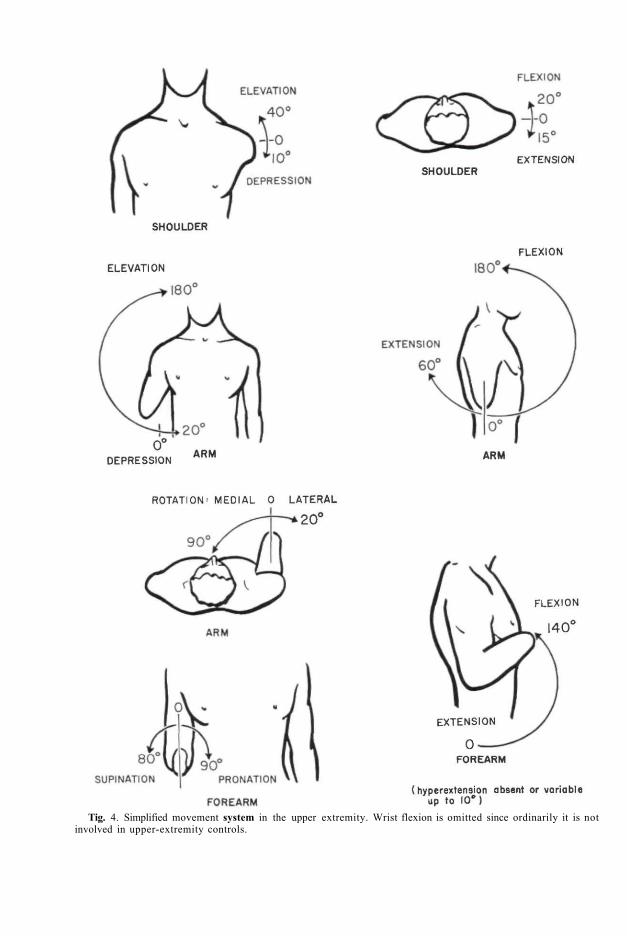
Tig. 4. Simplified movement system in the upper extremity. Wrist flexion is omitted since ordinarily it is not involved in upper-extremity controls.

clavicle, and the proximal end of the humerus. Anteriorly the lower fibers of the pectoralis major, the pectoralis minor, and the sub-clavius, and posteriorly the lower trapezius and latissimus, act as depressors.
Rotation of the scapula upward (i.e., right scapula, viewed from the rear, rotates counterclockwise) or downward (i.e., right scapula, viewed from the rear, rotates clockwise) is brought about by a special combination of the elevators and depressors. As shown in Figure 6, two portions of the trapezius, together with the serratus, cause upward rotation. Conversely, the pectorals, the latissimus, and the rhomboids cooperate to cause downward rotation. As will be seen later (page 13), the mechanical principle of the couple applies in these rotatory actions upon the scapula.
Flexion and extension of the shoulder involve as principal elements the abduction and adduction, respectively, of the scapula. The flexor muscles acting on the shoulder complex are the pectoralis major and minor, which swing the clavicle and acromion forward. The serratus anterior aids strongly by abducting the scapula. The extensors, placed posteriorly, include the latissimus, which pulls posteriorly and medially on the humerus, and the trapezius and rhomboids, which pull medially on the scapula.
The forward and backward shrugging of the shoulders with abduction and adduction, together with some upward and downward rotation of the scapulae, constitutes a major control source. Even in above-elbow amputees who use humeral flexion for forearm lift and for terminal-device operation at low elbow angles (page 22), scapular abduction is utilized for terminal-device operation at large angles of elbow flexion (e.g., when the terminal device is near the mouth). In shoulder amputees, both these operations depend wholly upon scapular abduction augmented by upward rotation.
Fig. 5. Skeletal anatomy of the shoulder region, a, Anterior view. b, Posterior view.
THE ARM
The Humerus and the Glenohumeral Joint
The humerus, together with its joint at the shoulder, comprises the skeletal machinery of the arm. As noted in Figure 4, it is capable of flexion-extension, elevation-depression, and rotation upon its proximal joint. The glenoid cavity, a lateral process on the scapula, receives the spherical surface of the humeral head. The glenohumeral articulation is therefore of true ball-and-socket character. The fibrous joint capsule is remarkable in that it envelops the humeral head and the glenoid margins in complete but rather loose fashion, so that a wide range of movement is possible. To some extent barometric pressure, but to larger extent the musculature spanning the joint, is responsible for keeping the articular surfaces together in all angular positions. A group of muscles including the subscapularis, the supraspinatus, and the infraspinatus function principally in this holding action.
B I O M E C H A N I C S OF CONTROL 9
Fig. 6. Schematic kinesiology of the shoulder girdle. L, latissimus; LS, levator scapulae; LT, lower trapezius; MT, medial trapezius; PM, pectoralis major; Pm, pectoralis minor; RM, rhomboid major; Rm, rhomboid minor; SA, serratus anterior; SC, subclavius; UT, upper trapezius.
Muscles and Movements The kinesiology of the arm is closely associ
ated with that of the shoulder girdle, nearly all natural movements involving a coordinated movement between arm and shoulder. It is helpful, however, first to describe the pure movements of the arm. Schematics of the muscles acting upon the arm are presented in Figure 7. Elevation is effected by the lateral deltoid and the supraspinatus, depression by the latissimus, the pectoralis major, the long head of the triceps, and the teres major. In both actions, the contributions of individual
muscles differ according to the angle of the arm. And it should be noted that, with insertions near the pivot point of the humeral head, the rotatory moments are proportionately small, thus accounting for the large number of muscles necessary to give adequate joint torques.
Arm flexion and extension are brought about by two groups of muscles. The biceps, the coraco-brachialis, the anterior deltoid, and the clavicular fibers of the pectoralis major mediate flexion, while the posterior deltoid, the long head of the triceps, the latissimus, and the teres major effect extension. Rotation of the arm depends upon muscles that insert on the surface of the humerus and then pass anteriorly or posteriorly around it to impart medial or lateral torsion. As would be expected, rotational forces are greatest when the arm hangs at the side; torque is reduced drastically when the arm is elevated over the head and the twisting angles of the muscles tend to disappear.
Combined Arm and Shoulder Movements In most natural arm movements,
such as arm elevation, arm flexion, forward reaching, and to-and-fro swings of the partially elevated arm, both arm and shoulder girdle
participate. In full arm elevation of 180 deg., for example, 120 deg. are contributed by rotation of the arm on the glenohumeral joint, 60 deg. are contributed by upward rotation of the scapula (17). In forward reaching, involving partial arm flexion, the shoulder flexes and the scapula abducts and rotates slightly. Properly managed, this motion, the common flexion control motion of both the above- and the below-elbow amputee (pages 19-22) can give marked gracefulness to prosthetic operation.
10 T A Y L O R

Fig. 7. Schematic kinesiology of the arm. AD, anterior deltoid; B, biceps; CB, coracobrachialis; IS, infraspinatus; L, latissimus; LD, lateral deltoid; PD, posterior deltoid; PM, pectoralis major; S, subscapularis; SS, supra-spinatus; T, triceps; TM, teres major; Tm, teres minor.
Fig. 8. The right elbow joint, viewed from in front. The thin capsular ligament is not shown. Note that the ulna, with its posteriorly projecting olecranon, forms a hinge joint with the humerus, while the head of the radius is free to rotate within the annular ligament.
THE FOREARM
Skeletal Members
The radius and ulna together constitute a forearm lever which can rotate about the elbow axis. By virtue of the arrangement at the proximal head of the radius and at the distal end of the ulna, the forearm can also carry out torsion about its longitudinal axis to produce wrist rotation. With the aid of the mobility at the shoulder and at the wrist, it is possible to place the hand in space in an almost unlimited number of positions. The skeletal anatomy of the elbow is shown in Figure 8, the articulations being the ulno-humeral and the radiohumeral. Participating in forearm rotation is the radioulnar joint at the wrist.
The ulnohumeral joint has an unusual structure. The complex surfaces of articulation between ulna and humerus are such that the axis of rotation of the forearm is not normal to the long axis of the humerus. As the elbow is flexed or extended, therefore, the forearm does not describe a plane. Instead, the ulna swings laterally as the elbow is extended, until at full extension the cubital angle is about 170 deg. Xevertheless, only small error is involved in considering the motion to be essentially that of a simple hinge with an axis of rotation perpendicular to ulna and humerus and allowing the ulna to swing through about 140 deg. of flexion.
In the radiohumeral joint, the slightly con
cave proximal end of the radius articulates with the hemispherical capitulum placed somewhat laterally on the anterior surface of the distal end of the humerus. The radius is free to move with the ulna through the complete range of flexion and, in addition, to rotate with forearm pronation and supination.
In the radioulnar joint, the distal end of the ulna forms a curved surface against which the radius opposes an articulating concavity. As
B I O M E C H A N I C S OF CONTROL 11

the forearm goes through a pronation-supination range of about 170 deg., the radius "swings like a gate" about the distal end of the ulna.
Muscles and Movements As shown in Figure 9, the musculature for
providing forearm flexion and extension is comparatively simple, while that for pronation-supination is somewhat more involved. Flexion of the forearm is effected principally by the biceps, originating on the scapula and inserting on the radius, and by the brachialis, spanning the elbow from humerus to ulna. Secondarily, the brachioradialis and other muscles, originating distally on the humerus and coursing down the forearm, contribute to flexion. Extension is largely the function of the triceps, originating on both the scapula and humerus and inserting on the leverlike olecranon process of the ulna. A small extensor action is added by the anconeus.
Rotation of the forearm is a function of many muscles. Some, such as the supinator, evidently are designed for the purpose, while others, as for example the finger flexors, have different principal functions, the contribution to forearm rotation being only incidental. Figure 9 presents the major rotatory muscles only. Supination is mediated by the brachioradialis, the supinator brevis, and the biceps, pronation by the pronators quadratus
and teres. Of great importance to upper-extremity prosthetics is the fact that rotation of the forearm is a function of total forearm length. With successively shorter stumps, not only are the rotation limits of the radius and ulna reduced, but also the contributions of muscles are eliminated as their insertions are sectioned.
Fig. 9. Schematic kinesiology of the forearm. A, anconeus; B, biceps; BR, brachialis; BrR, brachioradialis; PT, pronator teres; PQ, pronator quadratus; Su, supinator; T, triceps.
MUSCULOSKELETAL MECHANISMS
The upper extremity having been considered from the standpoint of functional and descriptive anatomy, attention may now be turned to a more mechanical view of its operations. Typical elements of mechanism in the upper extremity include joints (bearing surfaces), joint-lining secretions (lubricants), bones (levers and couple members), tendons (transmission cables), and muscles (motors). The arrangement of these elements makes up a complex machinery capable of such diverse activities as precise orientation in space, performance of external work, fine digital manipulations, and so on.
TYPICAL JOINT MECHANICS
The elbow joint embodies the essential structures of diarthrodial joints. The bearing surfaces are covered with a thin layer of articular cartilage that is continuous with the synovial membrane lining the whole joint capsule. Subsynovial pads of fat serve to fill up the changing spaces that occur during movement of the joint (Fig. 10). It is believed that these fatty deposits serve as "pad oilers" to maintain the continuous film of synovial fluid over the articular surfaces (4). This fluid contains mucin (a glycoprotein which serves as a lubricant for the joint) and other material constituting a nutritional medium for the articular cartilage. Considerable uncertainty exists concerning the method of formation and distribution of the fluid to the joint, but its mechanical function is clear and the normal joint performs as a well-oiled bearing.
BONES AND THEIR MECHANICAL FUNCTION
The bones of the upper extremity, besides forming a support for soft tissue, provide a system of levers which makes the arm an im-
12 T A Y L O R

portant mechanism for the performance of gross work, such as lifting, slinging, and thrusting. The arm bones serve further as positioners of the hand, in which other, finer bones constitute the intricate articulated framework of the manipulative mechanism. Two main features of bones merit discussion here—their internal composition and construction and their external shape and adaptations that permit them to serve as members of mechanical systems.
Internal Structure There is much evidence that the gross in
ternal structure of bone is eminently suited to withstand the mechanical stresses placed upon it by the compressive loads of weight-bearing, by the tensions of tendons and ligaments, and by the lateral pressures of adjacent tissues (4). The nature and orientation of the trabeculae in cancellous bone have, for example, long been held, in theory, to provide the maximum strength along the lines of major stresses. This idea, originally suggested by von Meyer, has been championed by many, including Koch, who carried out a stress analysis on the femur (12). Objections to the von Meyer
theory have dealt largely with the frequent and incautious extension of the concept. It is now believed that genetic and growth factors determine the essential form and dimensions of bone. Mechanical stresses serve secondarily to mold and modify it to give added strength where stresses are greatest. One must grant from even a superficial examination of the internal structure of bone that Nature has done an admirable job of designing for maximum strength with minimum weight.
Fig. 10. Typical change in joint spaces with flexion-extension, as revealed by the elbow. Redrawn from Steindler (17), after Fick. A, Gap of the medial border of the olecranon surface with elbow in extreme extension. B, Gap of the lateral border of the olecranon in extreme flexion.
Fig. 11. Force couples at the elbow. Tensile forces in biceps and brahialis are associated with equal, opposite, and parallel forces through the joint.
Members of Mechanical Systems The second principal feature of bones, that
of serving as rigid members in a complex of mechanical systems, is the one that has engaged the most attention. It is surprising that the simple lever concepts of Archimedes have persisted in anatomy and kinesiology texts to the present day. Thus, the forearm-flexor system is said to act as a third-class lever, the extensor system as a first-class lever. Although these assertions are of course true, both of these systems are, in the more complete language of Newtonian mechanics, parts of force-couple systems in which equal and opposite components of force are transmitted through the bones and joints (Fig. 11). Elft-man (7) has emphasized this view. The magnitude of the couple is given by the product of the force (either of the equal but opposite forces) and the distance between them, which also is numerically equal to the torque of the muscle force. The concept of the couple calls attention to the existence of the equal and opposite forces in joints and emphasizes the loads placed upon them by muscular work.
Another and more complicated application of the couple is seen in scapular rotation. Here, as described by Inman el al. (11) and as
shown in Figure 12, the pull of the lower fibers of the serratus anterior upon the scapula is such as to give it
B I O M E C H A N I C S OF CONTROL 13

upward rotation, while the thrust of the clavicle, acting through the acromioclavicular joint, holds a pivot for the rotation. Simultaneously, the pull of the upper trapezius fibers causes the clavicle to undergo angular rotation about the sternoclavicular joint. The result is that, at least through the first 90 deg. of arm elevation, the motion is shared by coordinated angular rotations of scapula, clavicle, and humerus. As a basic part of this rotatory action, the scapula acts as the moment
arm of a force couple, the trapezius and serratus providing components of force which are equal and opposite.
Fig. 12. Muscle forces acting on the shoulder, anterior view. The trapezius, acting diagonally, gives a supportive component. Fy,, and a horizontal component, Fx, which together with the opposite force from the serratus, 5, comprise an upward rotatory force couple on the scapula.
TENDONS AND MUSCLES
The specific functions of tendons are to concentrate the pull of a muscle within a small transverse area, to allow muscles to act from a distance, and in some instances to transmit the pull of a muscle through a changed pathway. The mechanical importance of this tissue is nowhere more evident than in the arm, where a large degree of versatility of motion in the segment distal to each joint is preserved by "remoting" the action of muscles through slender, cablelike tendons over joints. By this means lines of pull are brought near the joint axes, thus providing a lever arm consistent with the tensile force of the muscle at all joint angles and also giving at low joint angles an increased angular motion for a given linear contraction. Other advantages of remoting the muscles are seen in the forearm and hand. In order to afford the variety and complexity of interdigital movements, many independent
muscle units are necessary, and critical space problems are avoided because muscles such as the common flexors and extensors of the fingers are placed at some distance up the forearm.
The predominant function of tendon as a tension member in series with muscle, which is a tension motor, is seen in early growth stages. An undifferentiated cellular reticulum of connective tissue is everywhere found in embryonic tissue. The parent cells are fibroblasts; they elaborate and extrude the collagenous material of which white fibers are made (4). At this point the presence of mechanical tensions in the tissue influences the rate, amount, and direction of the resultant fiber formation. At maturity the tendon is composed almost entirely of white collagen fibers, closely packed in parallel bundles, to form a cablelike strand. It is contained within a sheath which forms a loose covering lubricated continuously by a mucinous fluid to reduce friction with surrounding tissues.
Mutual adjustment of the characteristics of muscle and tendon is shown in many respects. The musculotendinous juncture varies with the arrangement of the muscle fiber. It shows a simple series arrangement for fusiform muscles like the biceps, or it comprises a distributed attachment zone by continuation of the tendon into intramuscular septa where pinni-form fibers may insert (Fig. 13). In some unexplained way the relative lengths of muscle and associated tendon are so composed that the shortening range of the muscle is that necessary to move the segment distal to the joint through its maximum range (8). The capacity to adapt the ratio of muscle length to tendon length has been demonstrated in an experiment in which the pathway of the tibialis anterior tendon in the rabbit was shortened. The result was that the tendon shortened while the muscle lengthened to regain the normal joint range (4).
The relative strengths of muscle and of tendon also show an approximate compatibility, the tensile strength of tendon, measured at from 8700 to 18,000 lb. per sq. in. (6), being greater than that for muscle. Strength tests of excised muscle-tendon systems show that failure commonly occurs in the belly of the muscle, or at the musculotendinous juncture,
14 T A Y L O R
or at the bone-tendon juncture, but never exclusively in the tendon itself. Analysis of clinical cases indicates that muscle is still the site of failure even when it is maximally tensed (14). It is clear, then, that of the muscle-tendon combination the tendon is normally always the stronger.
Fig. 13. Muscle fiber patterns. A, Fusiform. B, Bipinniform.
Fig. 14. Forearm-flexor mechanics. Insert gives the geometry of the idealized flexor system.
FOREARM-FLEXOR MECHANICS
The forearm-flexor system is well suited to serve as an example of biomechanics because the bone-joint system comprises a simple uniaxial hinge while the flexor muscles, though five in number, can be reduced to a single equivalent muscle whose geometry and dynamics can be specified from measurement data. Figure 14 illustrates the lever system on
which the equivalent muscle acts. The angle between the axis of the muscle and that of the forearm bones, i.e., the "angle of pull," theoretically ranges from 0 deg. at full extension to 90 deg. at 100 deg. of elbow angle, and since the moment arm is continuously proportional to the sine of the angle of pull the mechanical advantage of the lever also is proportional to it.
There are of course departures from this idealized geometry. For one thing, the angle of pull and the elbow angle are not exactly equal. Moreover, at small elbow angles the torque component does not actually drop to zero because the muscles must always pass over the elbow joint at some finite distance from its center. Finally, the force-length curve (10) of the equivalent muscle must also be taken into account in expressing the effective torque. For these and other reasons, actual torque measurements take precedence over theoretical calculations, and the composite curve of Figure 14 has been plotted from the results of a number of investigators. Whereas the moment arm peaks at an elbow angle of 100 deg., the muscle force is declining throughout the elbow-flexion range, and the net effect, as reported by Miller (15), is a maximum torque of about 625 lb.-in. at from 80 to 90 deg. Clarke and Bailey (5) found a peak of about 400 lb.-in. at between 70 and 80 deg., and the author has obtained 550 lb.-in. just under 90 deg. in a group of subjects. Wilkie's data give a value of about 525 lb.-in. at 80
B I O M E C H A N I C S OF CONTROL 15
deg., measured on himself (22). These variations can be explained as resulting from the effect of a limited sampling of an inherently variable characteristic. Greater consistency probably could be obtained in a larger series of measurements.
Table 2
MAXIMUM TORQUES IN MAJOR ACTIONS
Because they express the fundamental output characteristics, and because they are most easily measured, the muscle torques about the major joints represent the most significant and practical aspects of the statics and dynamics of the musculoskeletal system. Not only is muscular power a concept of uncertain validity but also it is very difficult to measure. The combined effect of muscle and lever, however, can easily be measured in many subjects, so that statistical stability can be achieved in the results. Because muscle agonists change length with joint angle, and because they are thus caused to work on different parts of their length-tension diagrams, joint torques vary as a function of joint angle. As demonstrated by Clarke (5), this phenomenon, shown in Figure 14 for the forearm-flexor system, holds more or less for all major actions about the joints. But these details may be neglected in summarizing the maximum torques throughout the upper-extremity system (Table 2).
T H E FUNCTIONAL ROLE OF SOCKETS
The socket is the foundation of the upper-extremity prosthesis. It obtains purchase upon the most distal segment of the remaining member and should be stable, though comfortable, in its fit with this member. The socket must bear weight both axially and in all lateral directions. It is the attachment member for mechanical components and for control guides and retainer points. Hence the socket must be a sound structural member as well as a custom-fit, body-mating part. Finally, the socket extends the control function of the member to which it is fitted, giving movement and direction to the prosthesis. In any discussion of prosthetic controls, therefore, the starting point is the socket.
The requirement of formability and strength in sockets has been met satisfactorily by the introduction of polyester laminates (3,20). These materials permit close matching of the stump impression, and variations in strength can be introduced by increasing the number of laminate layers. The double-wall construction (3) provides a stump-fitted inner wall, with an outer wall that can be designed to structural uniformity and cosmetic requirement. Sizing to achieve this aim has now been reduced to standard practice (20). Finally, the texture and coloring of the plastic laminate can be controlled to achieve satisfactory cosmetic results.
16 T A Y L O R

Fig. 15. Below-elbow amputee types, based on average forearm length, epicondyle to styloid. After Taylor (18).
THE BELOW-ELBOW SOCKET
The peculiar feature of the forearm, that pronation-supination is a function of the whole forearm length, places a special limitation on the below-elbow socket. Although for stability in flexion the whole remaining forearm stump is best sheathed in the socket, to do so prohibits forearm rotation. In the case of the longer below-elbow stumps, therefore, some sacrifice in stability can be afforded in the interest of retaining forearm rotation. The proximal portion of the socket is fitted loosely to give freedom for forearm rotation while the distal portion is fitted snugly to provide a stable grip. Figure 15 shows the amount of forearm rotation available at various levels of the natural forearm and that remaining in below-elbow amputees of various types. Because of torsion of the flesh, however, and because of slippage between the skin and the socket, effective socket rotation is lost in stumps which are only 50 percent of forearm length. The effective socket rotation remaining in the wrist-disarticulation case is only about 90 deg.
Further adaptations of below-elbow sockets to suit the functional requirements at the various levels are shown in Figure 16. In the long below-elbow stump, the elliptical cross-section of the forearm near the wrist permits a "screw-driver" fit of the socket to yield the
maximum in rotational stability. With the shorter stumps, the possibility of effective rotation is reduced and is lost completely at about 50 percent of forearm length. At this level, the problem of forearm rotation is outweighed by that of providing flexion stability. Dependence upon a rigid or semirigid hinge system is necessary in the short below-elbow stump, and finally, in the very short stump, effective forearm flexion is so reduced that a split socket with step-up hinge becomes a necessity.
The goal of below-elbow socket design is to regain as completely as possible the control function of the forearm, which includes (a) positioning of the hand by forearm flexion and (b) hand rotation by means of pronation-supination. In the below-elbow prosthesis, adequate forearm flexion is obtained rather easily; rotation is limited to the potential available in the longer stumps. Manual wrist rotation, of course, supplements the remaining natural rotation. In the below-elbow prosthesis, then, control of the terminal device in space depends in fair measure upon the role of the socket in preserving the residual flexion and rotation of the below-elbow stump.
THE ABOVE-ELBOW SOCKET
Unlike the below-elbow case, the above-elbow stump presents no problem of diminish
ing rotation with diminishing stump length because arm rotation is confined wholly to the gleno-humeral joint. Socket design for the above-elbow case is therefore related principally to the requirement of fitting the stump closely so that the humeral lever can be fully effective in controlling the prosthesis. Figure 17 shows the minor variations corresponding to above-elbow type, including the elbow disarticulation. Sockets for the latter must take account of the bulbous end of the stump. They must provide snug fit around the epicondyle projections but maintain sufficient room in the region just above, where the stump cross-section is reduced, to permit
B I O M E C H A N I C S OF C O N T R O L 17

insertion of the stump in the socket. In both the elbow-disarticulation and the standard above-elbow cases, the upper margin of the socket is terminated below the acromion for freedom of movement at the shoulder. In the short above-elbow case, the socket is carried up over the acromion to obtain additional stabilization and suspension from
the shoulder, as required by the very limited stump area.
The control function of the above-elbow socket is twofold. As in the below-elbow case, the socket extends the slump to the next more distal joint and thus gives range and direction to this component upon which the positioning of the still more distal segments depends. But in addition to this feature, the above-elbow socket also has a power function. Through its attachments to shoulders and torso, it provides the forces and displacements needed to produce forearm flexion, terminal-device operation, and elbow lock. To fulfill these functions, the socket must have stable purchase on the stump in both flexion and extension. Hence, for elbow-disarticula
tion and above-elbow types, the socket should continue to the axillary level; for short-above-elbow amputees, it should come up over the acromion (Fig. 17). Finally, medial and lateral rotation of the socket are necessary for further functional positioning. Close fit and good suspension are required to give stability in these actions.
Fig. 16. Schematics of below-elbow prostheses. For each type, an insert gives the cross-sectional anatomy 1 in. from the end of the stump. Sections are taken from the normal anatomy of the forearm. Sockets, hinges, cuffs, and suspensions are for a, single socket; b, rotation type; c, double-wall socket; and d, split socket. After Taylor (18).
Fig. 17. Schematics of above-elbow sockets, including elbow disarticulation. For each type, an insert gives the cross-sectional anatomy at the indicated level. Dashed lines show stump contour and inner wall of the socket. Standard and short above-elbow cases have a double-wall socket.
18 T A Y L O R

Fig. 18. Schematics of shoulder sockets. Solid lines show residual bony s t ruc ture , dashed lines the body contour and inner wall of the socket. Disarticulation and forequarter sockets may be two-piece with sectional plates at a.
THE SHOULDER SOCKET
In the range of amputation sites from transection of the humeral neck to complete removal of the shoulder girdle, the socket form changes from shoulder cap to thoracic saddle. As displayed in Figure 18, the bearing area increases as the remaining shoulder elements are reduced; similarly, the amount of "build-out" needed to preserve shoulder outline increases with increasing amputation loss. With disarticulations and all more extreme losses, sectional plates may be introduced at the axillary parasagittal plane. This arrangement makes it possible to fabricate the prosthesis in two sections, a matter of considerable advantage to the limbmaker, and it also affords the functional advantage of a preposition swivel of the humeral section upon the saddle section to simulate flexion-extension of the arm.
The functional aspects of the shoulder socket are to some extent secondary to the structural; yet there are certain definite functional ends to be served. Shoulder and scapular mobility in elevation, flexion, and extension should be preserved to the highest possible degree. In humeral-neck and shoulder-disarticulation cases, aid can be given to the shrug control (biscapular abduction), and at least a small range of motion can be given to the elbow, but of course no such function can be expected in forequarter or partial-forequarter amputees.
MAJOR ARM AND SHOULDER CONTROLS
The common method of operation of upper-extremity prostheses is by means of shoulder harness which provides suspension and which also transmits force and excursion for control motions. In this manner such operations as forearm flexion-extension, terminal-device operation, and elbow lock are managed. Figure 19 presents the essential features of the major harness controls. In principle, each effective control must begin with a point
stabilized on shoulder or torso, pass over a voluntarily movable shoulder or arm part, and thus provide relative motions with respect to the origin. At the movable point, the control cable enters the Bowden-type housing, which transmits the relative motion independent of movements of the distal segments. Controls may be used singly or in combination, depending upon the level of amputation, amputee preference, and other practical considerations.
Besides the relative motions between various segments of the human body, still another source of energy for operation of upper-extremity prostheses can be made available by the surgical procedure known as cineplasty (1,19), in which a skin-lined tunnel is fashioned in the belly of a muscle group. In various experimental programs conducted both here and abroad, muscle tunnels have been made in the forearm flexors, the forearm extensors, the biceps, the triceps, and the pectoralis major.
Of all the various combinations tried, the biceps tunnel in below-elbow amputees has proved to be the most successful. Failure of other cineplasty systems has been due in some cases to inability of designers to overcome the mechanical problems involved in harnessing the energy thus provided and in other cases to the inherent properties of the particular muscle group concerned. In the below-elbow case, use of the biceps tunnel eliminates the need for shoulder harness and permits operation of the
B I O M E C H A N I C S OF CONTROL 19

prosthesis with the stump in any position. It has given excellent results in many instances and has been made available to those beneficiaries of the Veterans Administration who can make effective use of the procedure.
Fig. 19. Major harness controls. The points stabilized by harness (x) are beginning points for the control cable, which passes into a Bowden-type housing at movable points ( • ) . The relative motion is transmitted via the Bowden cable to distal points on the prosthesis.
The cineplasty tunnel in the biceps of the average male will provide sufficient force and excursion to operate modern terminal devices—an average maximum force of 50 lb. and 1 1/2 in. of useful excursion. It is not un-
20 T A Y L O R

usual for some individuals to be able to build up the force available to a value in excess of 100 lb., but such a high force normally is not required.
THE NATURE AND OPERATION OF CONTROL SYSTEMS
The Below-Elbow Single-Control System
The single control for the below-elbow amputee is powered by arm flexion to provide terminal-device operation. This control motion, used by the above-elbow amputee also, depends upon a coordinated flexion of the humerus and abduction of the scapula on the amputated side; little shoulder activity is required on the sound side. It is substantially the same motion as that used in normal unilateral reaching. The displacements of humerus and scapula are additive, so that the resulting motion is quite natural. With full Bowden-cable transmissions of power from arm cuff to forearm socket, there is no influence of elbow angle, and the operation is mastered easily by all amputees with stumps of 35 percent or more of normal forearm length.
The Below-Elbow Dual-Control System4
4 Although the terminology commonly used to describe the several control systems could well afford to be better systematized, it is adopted here because it is now so well established throughout the field of prosthetics. One may think of "dual control" as meaning that two control sources are involved in the provision of all necessary functions, but according to convention it means that two functions, specifically elbow flexion and terminal-device operation, are provided by a single control source, the third function, elbow lock, if needed, being managed by an additional control source. Yet "triple control" (page 22) in the accepted sense means not that three functions are furnished by a single control source but that three control sources are used to provide three functions, one for each.—ED.
In harnessing below-elbow stumps shorter than 35 percent of normal forearm length, it generally is necessary to use an auxiliary type of lift to help the amputee flex the forearm. This procedure is applicable to a split-socket type of prosthesis. It merely is an adaptation of the above-elbow dual-control system (page
22) using a lever loop positioned on the forearm section so that arm flexion may be utilized to assist in forearm lift. The cable housing is split and assembled so that when the arm is flexed the elbow will flex. The elbow hinge has no locking mechanism, the short below-elbow stump being used to stabilize the forearm. Normally, sufficient torque is available about the elbow axis to give adequate stability in all usable ranges.
In prescribing for a new amputee with this level of amputation, it might be advisable first to have the amputee try a split-type prosthesis without the below-elbow dual-control system. If, at time of initial checkout, the amputee cannot lift his forearm, or if he complains of painful contact with his stump, then of course the dual system is indicated. After the assist lift has been worn for some time, the remaining muscles of the stump may have hypertrophied, in which case the amputee might be able to discard the dual system and convert to the below-elbow single control.
The Below-Elbow Biceps-Cineplasty System
Force and excursion provided by the biceps muscle tunnel are harnessed by inserting into the tunnel a cylindrical pin of a nontoxic material and attaching a cable to each end of the pin. As in the other types of control systems, the Bowden-cable principle is employed to maintain a constant effective distance between the source of energy and the mechanism to be operated, regardless of relative motions occurring between body segments. In order that conventional terminal devices may be employed, it is necessary to join the two cables before attachment to the mechanism. Several devices for making this coupling are available commercially.
Suspension of the socket is provided by an arm cuff, which is attached to the socket by any of the various hinges normally used in fabrication of below-elbow prostheses. The arm cuff is fashioned in such a manner that forces tending to pull the prosthesis from the stump are absorbed by the condyles of the elbow rather than by the muscle tunnel.
B I O M E C H A N I C S OF CONTROL 21

The Above-Elbow Dual-Control System In above-elbow amputees, the humeral
stump furnishes the motive power for the three operations of the prosthesis—flexion of the forearm, operation of the terminal device, and management of the elbow lock. The first two operations are so linked mechanically that a single control motion, arm flexion, produces either terminal-device operation or forearm flexion, depending on whether the elbow is locked or unlocked (Fig. 20). Although the control motion by arm flexion in the above-elbow case is similar to that described for the below-elbow amputee, there are several differences. Because the cable passes through a lever loop on the forearm to give torque about the elbow, it is affected by elbow position. As the forearm is flexed, arm-flexion excursion is used up, and the excursion needed to operate the terminal device must come from scapular abduction (shrug), as in shoulder cases. Typically, the above-elbow amputee manages a full range of free forearm flexion by a normal arm-flexion movement. But in the elbow-angle range of from 90 to 135 deg., with elbow locked for terminal-device operation, he must call upon supplementary excursions from biscapular abduction. With the terminal device at the mouth, practically all operation depends upon shoulder shrug.
In the above-elbow dual-control system, operation of the elbow lock depends upon humeral extension and associated coordinations. When the forearm has been flexed to the position desired, the elbow lock is engaged by the arm-extension movement. Skill is needed
to maintain tension on the arm-flexion cable so that the arm does not drop during the locking control motion. Well-trained amputees elevate the arm moderately to compensate for the humeral extension and thus maintain the elbow angle. The extension control motion is complex. The humerus is simultaneously extended and elevated so that it moves obliquely to the side. During this phase, the point of the shoulder must be stabilized, or even moved forward, and the trapezius is bulged by downward rotation of the scapula (Fig. 21).
Fig. 20. Operation of above-elbow and shoulder dual controls.
The Above-Elbow Triple-Control System The triple-control system has been devised
to separate terminal-device operation from forearm lift. When the dual-control system is used, the amputee must select, by the use of the elbow lock, either terminal-device operation or forearm lifting. By separating forearm flexion and terminal-device operation, the triple control makes it possible for the terminal device to be controlled by an independent body motion. Although in general an above-elbow amputee fitted with triple control has an elbow lock, a few such cases are able to separate prehension from forearm flexion without use of the lock
A control cable from the terminal device is so attached and positioned that biscapular abduction or merely shoulder shrug will operate the terminal device through its full range of prehension. To lift the forearm the amputee uses arm flexion. Elbow-lock operation is accomplished in the same manner
as in the dual-control system, that is, by arm extension.
It is apparent that this arrangement will work best with a comparatively stable socket and a relatively long above-elbow stump. The chief advantage of the triple-control system is that at full forearm flexion the terminal device may still be operated through its complete range.
22 T A Y L O R
Fig. 21. Coordinated control motions for elbow lock. Simultaneously the humerus is both extended (a) and abducted (b) while the shoulder is depressed (c) and the trapezius is bulged (d) by downward rotation of the scapula.
The Shoulder Dual-Control System
In the absence of the humeral lever, the shoulder becomes the major power source, biscapular abduction controlling both forearm and terminal device in the dual-control system. The control path courses horizontally across the scapulae, and either opposite-axilla loop or basic chest-strap harness (page 46) captures the action satisfactorily. The combination afforded by the dual principle also is illustrated in Figure 20.
The shoulder amputee has a special difficulty in obtaining the combination of full forearm flexion and terminal-device operation because, unlike the above-elbow amputee, who can add the excursions of humeral flexion and scapular abduction, he must obtain all movement from biscapular abduction. Shoulder amputees with broad shoulders and wide chests usually achieve this action satisfactorily; others must accept the limitation of partial terminal-device operation at full forearm flexion. Partial-shoulder and fore-quarter amputees must depend upon the sound shoulder entirely, and in this case the action range of the terminal device typically is limited to not more than 90 deg. of forearm flexion.
In shoulder amputees, operation of the elbow lock must be managed by various special arrangements. The waist control, utilizing shoulder elevation; the perineal strap, based
on relative motion between shoulders and pelvis; the nudge control, requiring either manual or chin operation; extreme shoulder flexion on the sound side; and extension of the shoulder on the amputated side complete the array of known feasible possibilities. It is evident that with this class of amputees control motions will be slower and deliberately sequential. They are therefore necessarily more noticeable and awkward.
The Shoulder Triple-Control System
The harness required for the triple-control shoulder-disarticulation system consists of a chest strap for forearm flexion, a waist strap to operate the elbow lock, and an opposite-shoulder loop for prehension. The amputee must have excellent scapular abduction and must be able to separate it from extreme opposite-shoulder shrug, and he must have available good shoulder elevation on the amputated side. The chief advantage of the triple control in the shoulder-disarticulation case is identical to that of the triple control in the above-elbow case, namely, that the terminal device may be operated fully in the vicinity of the mouth. To operate the prosthesis from an extended position, the amputee first produces biscapular abduction, thus raising the forearm. Then, with the forearm held in place, he elevates the shoulder on the amputated side to lock the elbow. To operate the terminal device, he then flexes the sound shoulder. Excursion for terminal-device operation is thus unaffected by forearm flexion.
Unfortunately this system must be restricted to humeral-neck and shoulder-disarticulation cases. For lack of sufficient excursion on the amputated side, it is unlikely that a forequarter amputee would be able to use triple control.
MECHANICAL APPLICATION OF THE MAJOR CONTROLS
To elucidate practical amputee biomechanics, it is necessary to refer to several aspects of the connecting mechanism between amputee and prosthesis in the power-transmission system. Of first importance are the proximal retainers, which are located at the
B I O M E C H A N I C S OF CONTROL 23
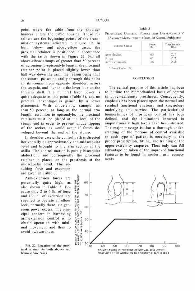
point where the cable from the shoulder harness enters the cable housing. These retainers are the beginning points of the transmission systems indicated in Figure 19. In both below- and above-elbow cases, the proximal retainer is positioned in accordance with the ratios shown in Figure 22. For all above-elbow stumps of greater than 50 percent of acromion-to-epicondyle length, the proximal retainer point is placed slightly lower than half way down the arm, the reason being that the control passes naturally through this point in its course from opposite shoulder, across the scapula, and thence to the lever loop on the forearm shell. The humeral lever power is quite adequate at this point (Table 3), and no practical advantage is gained by a lower placement. With above-elbow stumps less than 50 percent as long as the normal arm length, acromion to epicondyle, the proximal retainers must be placed at the level of the stump end in order to prevent undue tipping of the socket, as would occur if forces developed beyond the end of the stump.
In shoulder cases, the control path is directed horizontally at approximately the midscapular level and brought to the arm section at the axilla. The control motion is purely biscapular abduction, and consequently the proximal retainer is placed on the prosthesis at the midscapular level. The resulting force and excursion are given in Table 3.
Arm-extension forces are potentially quite high, as also shown in Table 3. Because only 2 to 6 lb. of force and 1/2 in. of excursion are required to operate an elbow lock, normally there is a generous power excess. The principal concern in harnessing arm-extension control is to obtain operation with minimal movement and thus to avoid awkwardness.
Fig. 22. Location of the proximal retainer for both above- and below-elbow cases.
CONCLUSION
The central purpose of this article has been to outline the biomechanical basis of control in upper-extremity prostheses. Consequently, emphasis has been placed upon the normal and residual functional anatomy and kinesiology underlying this service. The particularized biomechanics of prosthesis control has been defined, and the limitations incurred in amputations at high levels have been stressed. The major message is that a thorough understanding of the motions of control available to each type of patient is necessary to the proper prescription, fitting, and training of the upper-extremity amputee. Thus only can full advantage be taken of the improved functional features to be found in modern arm components.
24 T A Y L O R
LITERATURE CITED 1. Alldredge, Rufus H., Verne T. Inman, Hyman
Jampol, Eugene F. Murphy, and August W. Spittler, The techniques of cineplasly, Chapter 3 in Klopsteg and Wilson's Human limbs and their substitutes, McGraw-Hill, New York, 1954.
2. Carlyle, L. C, Using body measurements to determine proper lengths of artificial arms, Memorandum Report No. 15, Department of Engineering, University of California (Los Angeles), 1951.
3. Carlyle, Lester, Fitting the artificial arm, Chapter 19 in Klopsteg and Wilson's Human limbs and their substitutes, McGraw-Hill, New York, 1954.
4. Clark, W. E. Le Gros, The tissues of the body; an introduction to the study of anatomy, 3rd ed., Clarendon Press, Oxford, 1952.
5. Clarke, H. Harrison, and Theodore L. Bailey, Strength curves for fourteen joint movements, J. Assoc. Phys. & Ment. Rehab., 4(2):12 (1950).
6. Cronkite, Alfred Eugene, The tensile strength of human tendons, Anat. Rec, 64:173 (1936).
7. Elftman, H , Skeletal and muscular systems: structure and function, in Medical Physics, O. Glasser el al., eds., Vol. I, p. 1420, Year Book Publishers, Inc., Chicago, 1944.
8. Haines, R. W., On muscles of full and of short action, J. Anat., 69:20 (1934).
9. Hollinshead, W. H., Functional anatomy of the limbs and back; a text for students of physical therapy and others interested in the locomotor apparatus, Saunders, Philadelphia, 1951.
10. Inman, Verne T., and H. J. Ralston, The mechanics of voluntary muscle, Chapter 11 in Klopsteg and Wilson's Human limbs and their substitutes, McGraw-Hill, New York, 1954
11. Inman, V. T , J. B. deC M. Saunders, and L. C. Abbott, Observations on the function of the shoulder joint, J. Bone & Joint Surg., 26:1 (1944).
12. Koch, John C, The laws of bone architecture, Am. J. Anat., 21:177 (1917).
13. Lewis, Warren H., ed., Gray's anatomy of the human body, 24th ed. revised, Lea and Febiger, Philadelphia, 1942.
14. McMaster, Paul E., Tendon and muscle ruptures; clinical and experimental studies on the causes and location of subcutaneous ruptures, J. Bone & Joint Surg., 15:705 (1933).
15. Miller, D. P., A mechanical analysis of certain lever muscles in man, Ph.D. dissertation, Graduate School, Yale University, New Haven, Conn., 1942.
16. Newman, R. W., and R. M White, Reference anthropometry of Army men, Report No. 180, Quartermaster Climatic Research Laboratory, Lawrence, Mass., 1951.
17. Steindler, Arthur, Kinesiology of the human body tinder normal and pathological conditions, Charles C Thomas, Springfield, Ill., 1955.
18. Taylor, Craig L., The biomechanics of the normal and of the amputated upper extremity, Chapter 7 in Klopsteg and Wilson's Human limbs and their substitutes, McGraw-Hill, New York, 1954.
19. Taylor, Craig L., Control design and prosthetic adaptations to biceps and pectoral cineplasly, Chapter 12 in Klopsteg and Wilson's Human limbs and their substitutes, McGraw-Hill, New York, 1954.
20. University of California (Los Angeles), Department of Engineering, Manual of upper extremity prosthetics, R. Deane Aylesworth, ed., 1952.
21. Unpublished data, UCLA. 22. Wilkie, D. R., The relation between force and velocity
in human muscle, J. Physiol., 110:249 (1949)
B I O M E C H A N I C S OF C O N T R O L 25

Harness Patterns for Upper-Extremity Prostheses
ROBERT J. PURSLEY, Lt., USA (MSC)1
1 Chief, Research Limb Section, Army Prosthetics Research Laboratory, Walter Reed Army Medical Center, Washington, D. C,
The comparatively recent development of more functional components for artificial arms has made it necessary to analyze in greater detail the requirements of harnessing the power needed for effective operation. Just as an automobile is helpless without a well-designed and well-built engine and transmission system, so an arm prosthesis is helpless without a well-designed and well-constructed harness. To build a successful harness system requires not a knowledge of some long-lost art but, instead, a careful appraisal of the wearer, of the device to be worn, and of the available tools to be put to work. Since the modern body harness constitutes a dynamic coupling between a human being and a mechanism designed to replace a living extremity, the problem of devising it is also one of dynamics and of what some call "human engineering."
Many illustrations of typical harness patterns are presented later in this article. But it is not enough for the harnessmaker simply to reproduce what is shown in these drawings of typical patterns or to superimpose on an individual amputee a generalized harness pattern of any particular type. He must first understand the purpose of the harness, the requirements of the particular prosthesis involved, and the body motions available, and he must then apply his own skill and judgment in making appropriate modifications to suit the individual case. It is, of course, far more important to produce a harness that will give the desired functional results than it is to produce one that looks exactly like any one of the drawings. The illustrations are therefore
intended as general guides only, not as a detailed description applicable to every case of amputation at the indicated level. When planning and making any harness, the prosthe-tist should examine the location of each element to ensure proper function with the expenditure of minimum effort on the part of the particular wearer concerned.
The first and most simple requirement of any harness is that it must hold the prosthesis securely on the stump. The second is that it must be comfortable to the amputee. Generally, suspension, as such, is easily obtained, but to suspend the prosthesis properly and at the same time to assure maximum comfort for its wearer is more difficult. If either of these requirements becomes a matter of choice, then comfort must be the more important consideration. If the harness is not comfortable, or at least tolerable, the person for whom it was intended will soon hang it politely on a suitable nail. Since almost no harness can be constructed satisfactorily without a few compromises at first, it is unwise to promise complete success on the first try.
The third and all-important requirement of functional body harness is that it must supply a source of power for the operating components of the prosthesis. This means simply that residual body motions must be harnessed to replace lost functions of the natural member, but to provide controls that are operable in an effective and yet inconspicuous manner poses a complex problem. It requires an examination of the body motions that can be utilized by the harness without detracting from the usefulness of the remaining normal hand and without introducing unduly awkward gyrations of parts of the anatomy not ordinarily involved
26

in arm activity. The higher the level of amputation, the greater the control requirements but the fewer the sources of control. The problem is further complicated by the need to maintain the proper balance between adequate suspension, acceptable comfort, and worthwhile function, for each of these needs is often satisfied only at the expense of the other two.
A look at the background of harnessing for upper-extremity prostheses (7,8,9,15,17,22) reveals that, when devices were generally passive in nature, so was the harness. As devices have increased in function, so has the harness also. Today the development of devices has in general surpassed the art of harnessing them. With the proper approach, however, and using a common-sense analysis both of the amputee's capabilities and of the requirements of the prosthesis, an accomplished limbfitter can in almost every case turn out a very acceptable harness that will meet functional needs to a surprising degree.
HARNESSING FOR THE BELOW-ELBOW CASES
The prosthesis for the unilateral below-elbow case is unquestionably the simplest to harness. For the reason that the below-elbow amputee retains his own elbow, and therefore usually requires replacement of prehension only, he can almost without exception be harnessed successfully. At least three feasible control motions are to be had. In order of decreasing usefulness, they are arm flexion on the amputated side, shoulder depression on the amputated side, and scapular abduction. The choice and extent of use of these three motions, singly or in combination, is largely a matter of personal preference depending on the area in which the terminal device is required to operate. With the elbow flexed to 90 deg. and with the terminal device located slightly above the level of the head, for example, arm flexion is almost completely spent. Using scapular abduction under the same circumstances, however, the below-elbow amputee can still operate the terminal device satisfactorily. Successful wearers of below-elbow prostheses develop their own individual patterns of operation and subconsciously learn to operate the device in all areas in which it is called upon.
The problem of transmitting the force and excursion of body motions from the source to the point of use has in the past involved a wide variety of materials. Rawhide thongs and leather laces are only two of many that have been used, even as late as only a decade ago (1). The flexible metal cable and wrapped-wire housing adopted from the aircraft industry is currently the most widely used and is the most satisfactory available today. It is based on the Bowden principle (Fig. 1), which makes it possible to transmit force and excursion from the body to the terminal device regardless of elbow angle (21).
Utilizing any or all of the three useful body motions, together with the Bowden-cable transmission system in every case, two alternate harness patterns are available for the below-elbow amputee with a stump of medium length. The first is known as the "figure-eight" harness, the second as the "chest-strap" harness. In addition, there are two special modifications, one for the very long and another for the very short below-elbow stump. These are, respectively, the "double-axilla-loop" harness and the "dual-control" harness. Finally, there is the special harnessing arrangement using the biceps cineplastic muscle tunnel to provide force and excursion.
Fig. 1. The principle of the Bowden cable for transmitting tension forces applied at one end. Although point C is brought closer to point A when rotation occurs about B, the housing D prevents slack in cable E by preserving the effective path length A to C. A counter-force is required at the opposite end to return the flexible cable to its original position. Other types of Bowden cables are based on the torque principle, as used in speedometer cables, or the push-pull principle, as used in the temperature controls of the automobile heater.
H A R N E S S P A T T E R N S 27

Fig. 2. The below-elbow figure-eight harness. A simple webbing loop passes around the sound shoulder, the front portion being used for suspension, the back for attachment of the control cable. The inverted Y-suspensor. triceps pad, and flexible elbow hinges are constructed of 4 to 6-oz. strap leather and lined with 4-oz. pearl horse-hide or equivalent. The proximal retainer on the triceps pad is of the flexible leather type to improve cable life. The three circled inserts show possible variations in individual cases. Circle A illustrates the leather half-cuff as used in combination with rigid elbow hinges and a single billet. Circle B shows a hall-cuff with two billets, again in combination with rigid elbow hinges. Circle C shows the inverted Y-strap as made from fabric instead of leather. Any of the combinations shown may be used as required to furnish the necessary stability depending upon occupational needs, level of amputation, and other factors.
THE BELOW-ELBOW FIGURE-EIGHT HARNESS
The Harness Pattern
The figure-eight pattern, of which Figure 2 presents a typical example, is the harness most commonly used in the unilateral below-elbow case, the axilla on the sound side being the site of anchor for capturing the relative motion. The front view of Figure 2 shows the suspension portion of the harness. The front harness strap, passing over the shoulder at the
pectoral interval on the amputated side, buckles to the inverted Y-strap supporting the leather triceps pad, which in turn supports the socket through the flexible elbow hinges. The back view shows the transmission system from harness to terminal device. The general path of the control cable is such that sharp bends and curves of small radius are avoided as much as possible.
The chief purpose of the control system is to transmit force and excursion to the terminal
28 P U R S L E Y

device. When, however, the amputee must pick up loads with forearm extended, the cable is expected to assist in support whenever the load is of any appreciable magnitude. This, then, is an example of what is meant by the proper balance of forces that is needed to meet amputee requirements. Both suspension and control system should be so constructed and adjusted as to be comfortable and yet be able to meet a reasonable load-support requirement without unnecessary displacement of the prosthesis. Tests for determining allowable displacements and other important factors have been set forth by Carlyle (5,6).
As shown in Figure 2, the harness is padded and protected under the axilla, and the control cable is so adjusted that it cannot come into contact with the amputee's back. For maximum excursion, the cross of the harness should be below the cervical vertebrae and not more than 1 in. toward the sound side of the vertebral spine. The control attachment strap (i.e., the strap attached to the flexible control cable) should lie at the midscapular level. In the course of constructing the harness, visual observations of all these details should be made while the wearer goes through the movements to be expected in normal use.
Because of the simplicity of the figure-eight harness, minor deviations usually are not serious. Occasionally, indeed, exceptions to the normal placement of the harness cross are necessary and desirable to improve comfort. The figure-eight harness can be worn successfully by the majority of below-elbow amputees with ordinary duties, it is easy to construct and there is little chance for error, and it is functional and comfortable in most cases. Together these advantages generally represent the reason why it is so widely used. It readily adapts itself to vocations that are clerical in nature and to individuals requiring medium duty, such, for example, as the lifting that might be required of a stockroom worker.
Below-Elbow Cliffs, Pads, and Hinges To furnish suspension and socket stability,
three types of cuffs and pads, with and without fillers, are available, and any of several types of hinges, some flexible and some rigid, may be used. The circled inserts A and B of Figure
2 show some of the variations giving greater and greater stability as needed in the individual case. The choice of cuff and hinge combination is strictly a consideration for the prescription team, the rule being to provide maximum stability with the absolute minimum of harness. Prescription criteria and suitable templates for cuffs are described in considerable detail in Section 5.6 of the Manual of Upper Extremity Prosthetics (27). It should be remembered that many combinations of hinges and cuffs are available and that no one cuff must necessarily be accompanied by any particular type of hinge. Moreover, the prescription for any given amputee should take into account his own individual requirements and personal preferences.
There are at least two ways of making cuff suspension systems, material selection being the principal distinguishing factor. The preference of the limbmaker may enter into the choice of technique largely because of the fabrication facilities that happen to be available. Leather has long been used in the limb industry, and it is readily adaptable because of its molding characteristics. Although the ability of leather to conform readily to the shape of the arm represents something of an advantage over webbing straps (circled insert C of Figure 2), its tendency to absorb perspiration and thus to deteriorate, as well as to acquire unpleasant odors, is considered by many to be a distinct argument against its use in arm cuffs. The webbing strap, while perhaps less stable, offers the advantage of being easily washed and quickly replaced. Modern synthetic fabrics now available commercially can be laundered without undue shrinkage and may be reapplied without stretching under load.
The below-elbow cuffs and pads usually are made of 4- to 6-oz. strap leather and are lined with horsehide or similar material. The fabrication of this component calls for the cutting, sewing, and fitting skills of the limbmaker. To make the Y-shaped leather suspension strap, a paper pattern is first cut to conform to the amputee's arm. When the template lies smoothly against the arm above the bulge of the biceps and will reach properly from the triceps pad or cuff to the webbing suspension
H A R N E S S P A T T E R N S 29
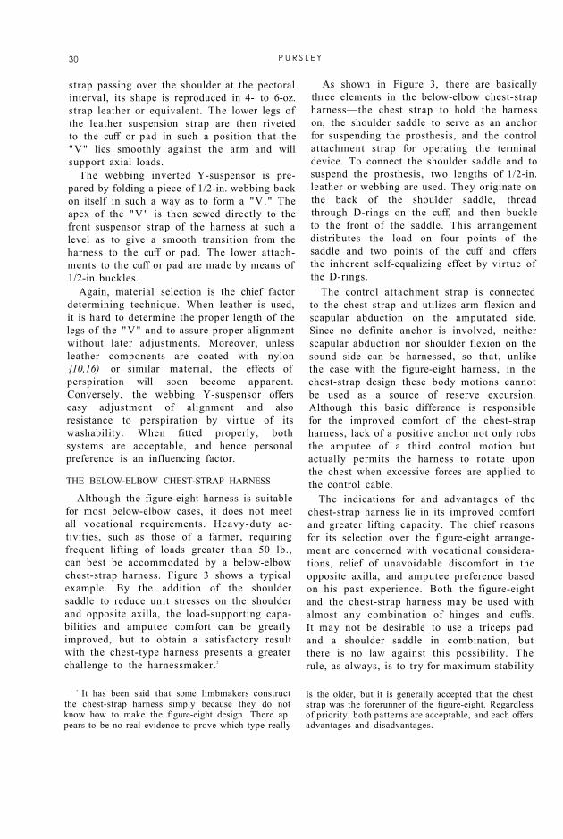
strap passing over the shoulder at the pectoral interval, its shape is reproduced in 4- to 6-oz. strap leather or equivalent. The lower legs of the leather suspension strap are then riveted to the cuff or pad in such a position that the "V" lies smoothly against the arm and will support axial loads.
The webbing inverted Y-suspensor is prepared by folding a piece of 1/2-in. webbing back on itself in such a way as to form a "V." The apex of the "V" is then sewed directly to the front suspensor strap of the harness at such a level as to give a smooth transition from the harness to the cuff or pad. The lower attachments to the cuff or pad are made by means of 1/2-in. buckles.
Again, material selection is the chief factor determining technique. When leather is used, it is hard to determine the proper length of the legs of the "V" and to assure proper alignment without later adjustments. Moreover, unless leather components are coated with nylon {10,16) or similar material, the effects of perspiration will soon become apparent. Conversely, the webbing Y-suspensor offers easy adjustment of alignment and also resistance to perspiration by virtue of its washability. When fitted properly, both systems are acceptable, and hence personal preference is an influencing factor.
THE BELOW-ELBOW CHEST-STRAP HARNESS
Although the figure-eight harness is suitable for most below-elbow cases, it does not meet all vocational requirements. Heavy-duty activities, such as those of a farmer, requiring frequent lifting of loads greater than 50 lb., can best be accommodated by a below-elbow chest-strap harness. Figure 3 shows a typical example. By the addition of the shoulder saddle to reduce unit stresses on the shoulder and opposite axilla, the load-supporting capabilities and amputee comfort can be greatly improved, but to obtain a satisfactory result with the chest-type harness presents a greater challenge to the harnessmaker. 2
2 It has been said that some limbmakers construct the chest-strap harness simply because they do not know how to make the figure-eight design. There ap pears to be no real evidence to prove which type really
is the older, but it is generally accepted that the chest strap was the forerunner of the figure-eight. Regardless of priority, both patterns are acceptable, and each offers advantages and disadvantages.
As shown in Figure 3, there are basically three elements in the below-elbow chest-strap harness—the chest strap to hold the harness on, the shoulder saddle to serve as an anchor for suspending the prosthesis, and the control attachment strap for operating the terminal device. To connect the shoulder saddle and to suspend the prosthesis, two lengths of 1/2-in. leather or webbing are used. They originate on the back of the shoulder saddle, thread through D-rings on the cuff, and then buckle to the front of the saddle. This arrangement distributes the load on four points of the saddle and two points of the cuff and offers the inherent self-equalizing effect by virtue of the D-rings.
The control attachment strap is connected to the chest strap and utilizes arm flexion and scapular abduction on the amputated side. Since no definite anchor is involved, neither scapular abduction nor shoulder flexion on the sound side can be harnessed, so that, unlike the case with the figure-eight harness, in the chest-strap design these body motions cannot be used as a source of reserve excursion. Although this basic difference is responsible for the improved comfort of the chest-strap harness, lack of a positive anchor not only robs the amputee of a third control motion but actually permits the harness to rotate upon the chest when excessive forces are applied to the control cable.
The indications for and advantages of the chest-strap harness lie in its improved comfort and greater lifting capacity. The chief reasons for its selection over the figure-eight arrangement are concerned with vocational considerations, relief of unavoidable discomfort in the opposite axilla, and amputee preference based on his past experience. Both the figure-eight and the chest-strap harness may be used with almost any combination of hinges and cuffs. It may not be desirable to use a triceps pad and a shoulder saddle in combination, but there is no law against this possibility. The rule, as always, is to try for maximum stability
30 P U R S L E Y
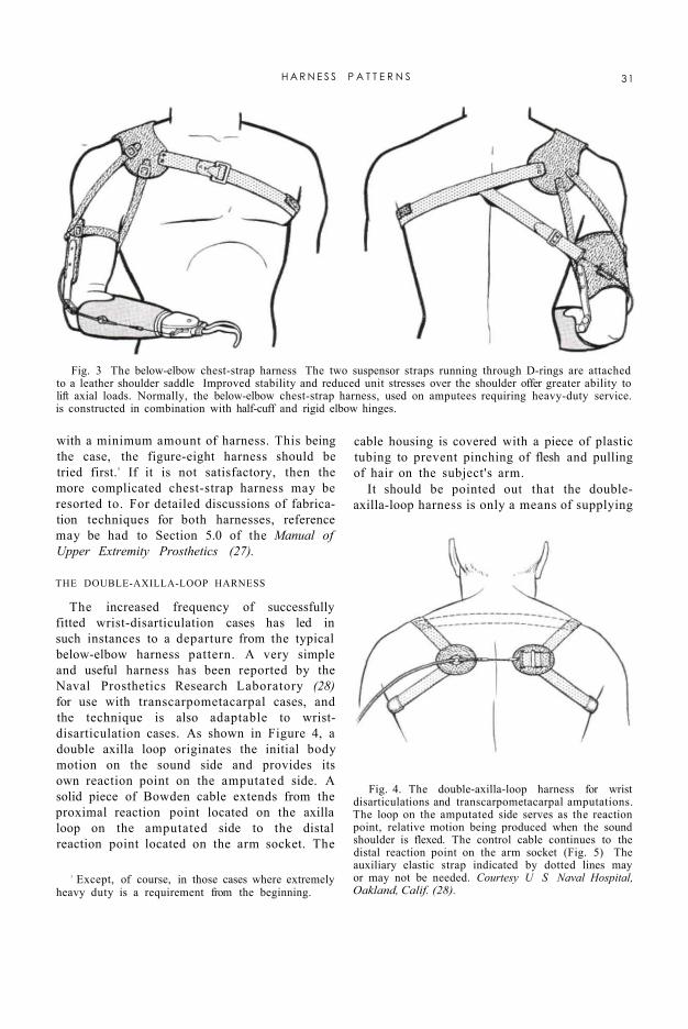
with a minimum amount of harness. This being the case, the figure-eight harness should be tried first.3 If it is not satisfactory, then the more complicated chest-strap harness may be resorted to. For detailed discussions of fabrication techniques for both harnesses, reference may be had to Section 5.0 of the Manual of Upper Extremity Prosthetics (27).
Fig. 3 The below-elbow chest-strap harness The two suspensor straps running through D-rings are attached to a leather shoulder saddle Improved stability and reduced unit stresses over the shoulder offer greater ability to lift axial loads. Normally, the below-elbow chest-strap harness, used on amputees requiring heavy-duty service. is constructed in combination with half-cuff and rigid elbow hinges.
Fig. 4. The double-axilla-loop harness for wrist disarticulations and transcarpometacarpal amputations. The loop on the amputated side serves as the reaction point, relative motion being produced when the sound shoulder is flexed. The control cable continues to the distal reaction point on the arm socket (Fig. 5) The auxiliary elastic strap indicated by dotted lines may or may not be needed. Courtesy U S Naval Hospital, Oakland, Calif. (28).
3 Except, of course, in those cases where extremely heavy duty is a requirement from the beginning.
THE DOUBLE-AXILLA-LOOP HARNESS
The increased frequency of successfully fitted wrist-disarticulation cases has led in such instances to a departure from the typical below-elbow harness pattern. A very simple and useful harness has been reported by the Naval Prosthetics Research Laboratory (28) for use with transcarpometacarpal cases, and the technique is also adaptable to wrist-disarticulation cases. As shown in Figure 4, a double axilla loop originates the initial body motion on the sound side and provides its own reaction point on the amputated side. A solid piece of Bowden cable extends from the proximal reaction point located on the axilla loop on the amputated side to the distal reaction point located on the arm socket. The
cable housing is covered with a piece of plastic tubing to prevent pinching of flesh and pulling of hair on the subject's arm.
It should be pointed out that the double-axilla-loop harness is only a means of supplying
H A R N E S S P A T T E R N S 31
terminal-device operation. Suspension must be inherent in a well-fitted socket, which usually must be split to facilitate donning, the condyles of the wrist being the principal means of retaining the socket on the stump (Fig. 5). Wrist disarticulations can be fitted by this technique at first. If it proves to be unsuccessful for any reason, the harness may easily be replaced with a conventional below-elbow figure-eight harness (29).
THE BELOW-ELBOW DUAL-CONTROL SYSTEM
As opposed to the problem of fitting the wrist disarticulation and other long below-elbow stumps, there is the one involving the fitting and harnessing of the very short below-elbow slump. Use of the split-socket type of prosthesis furnishes a means of increasing the range of elbow flexion through a mechanical step-up. Thia expedient greatly improves the versatility of the below-elbow prosthesis and in the majority of cases proves to be very satisfactory when using the below-elbow figure-eight harness based on the single-control principle.
For marginal cases with insufficient torque about the elbow to lift the prosthetic forearm, another departure has been made from the usual pattern of control. The below-elbow dual-control system, shown in Figure 6, uses a forearm lever loop and a split-housing cable system. Since in this case the cable housing is in two separate pieces, the effective distance between the reaction point on the arm cuff and that constituted by the lever loop on the forearm shell is no longer independent of elbow angle, so that arm flexion produces
forearm flexion. When used with the very short below-elbow stump, the dual-control system thus provides an assistive lift for forearm flexion, sometimes especially needed when forearm flexion is begun from full forearm extension. Ordinarily the short below-elbow case has enough torque about the elbow to stabilize the forearm, so that no elbow lock is required. When the forearm socket is stabilized by the stump, the force from the harness is transmitted to the terminal device.
The familiar rule of first trying the less complicated harness should be applied at this level also. If the forearm cannot be flexed by the stump without unnecessary fatigue, or if forearm flexion is painful, then the dual system is indicated. Amputees fitted with the dual control should be checked periodically to see whether the residual muscles have hy-pertrophied enough to be adequate for unassisted forearm flexion, in which event the single control may be substituted. No harm is done by using the below-elbow dual-control harness when its necessity is questionable, but again the usual desirability of simplicity of harness would suggest discard of the assist lift when adequate function can be obtained without it.
Fig. 5. Wrist-disarticulation socket for use with the double-axilla-loop harness. Control cable extends to the proximal reaction point located on the axilla loop on the amputated side (Fig. 4).
THE BELOW-ELBOW BICEPS-CINEPLASTY SYSTEM
The Case for Cineplasty in General
Since World War II , there has been, especially in the United States, a considerable revival of cineplastic surgery (2,14,24,26) to produce muscle tunnels capable of harnessing for the operation of artificial arms. Practically all available muscles of the arm and two major muscles of the chest (the pectoralis major and minor) have been harnessed by various means to operate arm prostheses. Two basic philosophies have developed in the use of the cineplastic muscle tunnel. First established was the idea of using the muscle motor to power the terminal device. The advantages of this means of independent terminal-device operation, without relying upon body motions, were readily apparent, to say nothing of the possibility of eliminating body harness completely in some cases.
Some authors, for example Mount and
32 P U R S L E Y

Bernberg (19), discuss the advantages of an increased sense of pressure and generally improved sense of perception when a muscle motor is harnessed to a terminal device. Mount and Bernberg say "The results generally indicate that the two Ss [subjects] using cine-plastic prosthesis distinguished, compared and recognized given objects with greater skill and precision than the Ss [subjects] using prosthesis of the harness type." Although further scientific tests to support this observation have not been conducted, subjects successfully fitted with both a conventional and a cineplastic prosthesis indicate that they have a better sense of pressure or feel with the latter.
In the second philosophy developed, the pectoral tunnel is used to operate the elbow lock in the shoulder-disarticulation case. Obviously, the advantage in this case lies in the provision of the additional source of control.
It may be stated, without reservation, that of all the possible arrangements involving cineplasty, the greatest degree of success has been obtained using the biceps muscle tunnel to power terminal-device operation in the below-elbow case. This does not mean that the combination of other muscle tunnels and other levels of amputation may not be successful in individual cases. Spittler and Fletcher (24), Kessler (14), Alldredge et al. (2), and Taylor (26) report other muscles and other
levels of amputation successfully fitted with cineplastic prostheses. Because, however, the other cases have not yet been proven clinically in the general sense, the discussion of the fitting of cineplasty is here restricted to the below-elbow biceps system.
In the below-elbow biceps case, fitting is greatly simplified because the muscle tunnel is above the first sound joint in the amputated stump. The socket may thus be made to harness residual pronation and supination,
and it does not require window-type construction (26) since the tunnel is once removed in the upper arm.
Fig. 6. The below-elbow dual control using the split-socket type of prosthesis for the short below-elbow case. Since the cable housing is in two pieces, arm flexion assists in lifting the prosthetic forearm. The stump is then used to stabilize the elbow for terminal-device operation, no elbow lock being needed. The design of the step-up elbow hinges has been discussed in detail by Alldredge and Murphy (1).
4 Although common-sense logic might lead one to suppose that improvement in pressure appreciation would be obtainable only were the terminal device voluntary-closing, it turns out that considerable improvement is to be had also from muscle tunnels harnessed to voluntary-opening devices. The tests conducted by Mount and Bernberg (19) were, for example, all made with amputees wearing voluntary-opening hooks. How does the amputee so fitted estimate the amount of force being exerted at the hook fingers? He measures "holdback" and subtracts it mentally from the known total force exerted by the hook when no restraint is applied.—ED.
Because the biceps tunnel in the below-elbow case is able to avail itself of the physiological characteristics of muscle (13), adequate force and excursion are to be had. Since normally muscles are contracted to produce prehension, contraction of the biceps muscle tunnel should effect closing of the terminal device. For this reason it is generally accepted that a voluntary-closing device is most desirable for use with cineplastic amputees. Of course if the improved sense of pressure is to be had, then it may be best to use the voluntary-closing terminal device. Regardless of all data presented here and elsewhere, however, many biceps tunnels have been successfully harnessed in the below-elbow case with the voluntary-opening terminal device.4 This
H A R N E S S P A T T E R N S 33

circumstance can only suggest that the prescription of the terminal device in cineplasty is largely in the same area as is the prescription of the terminal device in the conventional case using body harness.
The back-and-forth discussion of these factors is endless. It is therefore useful to have a look at the indications for cineplasty as seen from the point of view of the amputee. Needless to say that, in the growth of prosthetics clinic teams, new amputees are seeing more and more the types of prostheses worn by other amputees. Usually when the wearer of a conventional arm prosthesis sees a cineplastic type he feels that a "Cadillac" version of an artificial arm is available for him. No doubt personal choice, or the individual desire for a cineplastic type of prosthesis, is the major consideration. Amputees who were not too favorable at the time of discussing the cineplasty procedure have not obtained the same degree of success and training as have those who indicated their preference for cineplasty from the beginning.
Another important factor relates to vocation. If a below-elbow amputee desires to do, for example, mechanical work on an automobile, he often finds himself lying on his back on a dolly. In this position, he is quite restricted in body motions for using a shoulder-harness prosthesis. For the wearer of a conventional prosthesis to operate his terminal device in this position involves the use of many body motions other than those ordinarily involved.
Although no real criterion has yet been developed for the selection of individuals for the cineplasty type of prosthesis, it can be stated categorically that the personal preference of the individual and the vocational considerations are of prime importance and should therefore be discussed thoroughly with the patient before reaching a decision.
Fig. 7. The UCLA below-elbow biceps-cineplasty system with epicondyle cuff and rigid elbow hinges. The twin cable mounting is connected to the yoke to allow positioning for adequate operating excursion.
The Two Established Systems
Prosthetic fitting and socket construction for a biceps-cineplasty below-elbow prosthesis are very similar to the conventional techniques. The socket must provide stability and a means of attaching a terminal device. Suspension of the prosthesis may be handled in various ways. Two power-transmission systems have been
developed, one at the University of California at Los Angeles and the other at the Army Prosthetics Research Laboratory. A comparison of the efficiencies of the two systems has revealed that they have quite similar characteristics (3).
The UCLA Below-Elbow Biceps-Cineplasly System. The power-transmission system of UCLA consists of a muscle-tunnel pin, a dual-cable power-transmission system, and a twin cable mounting harnessed to the terminal device. All parts of this system, shown in Figure 7, have been available commercially for some time, and the arrangement has received wide use in the field. Three types of cuffs are available for suspension in the UCLA system. The epicondyle cuff (Figs. 8 and 9), the epicondyle clip (Fig. 10), and the epicondyle strap (Fig. 11) may be used with any selection of either flexible or metal double- or single-axis elbow hinges. The method of installing the UCLA system is described in detail in Section 10.0 of the Manual of Upper Extremity Prosthetics (27).
34 P U R S L E Y

Fig. 9. Alternative design of the UCLA epicondyle cuff, constructed of stainless steel and covered with horsehide, the rigid hinges being attached to the cuff before covering. The cross strap at the top helps to stabilize the cuff on the arm.
Fig. 8. Pattern for the UCLA epicondyle cuff.
The UCLA system is quite adequate and very simple to harness and provides easy pre-positioning and ready adjustment of effective cable length. It has met with a very large degree of success throughout. Compared to the APRL system (3), it offers the advantage of being applicable to a wider selection of terminal devices inasmuch as the control system may be mounted either on the top or on the bottom of the arm socket (Fig. 12). It offers also the advantage of allowing pre-positioning of terminal devices with less friction throughout the cable system.
The APRL Below-Elbow Biceps-Cineplasty System. The APRL system, as it appears in the Manual of Upper Extremity Prosthetics {27), has been revised to improve function. The principal modifications (Fig. 13) have been to adopt flexible leather hinges and to
discard the so-called "transit elbow hinges." Since these changes (4), indications have pointed to a greater degree of success when the biceps tunnel is used with a voluntary-closing terminal device.
Although both the voluntary-closing and voluntary-opening hands and hooks are recommended routinely for use with biceps tunnels in below-elbow amputees, experience has shown that voluntary-closing devices have offered a number of special advantages. The available excursion can be increased by utilizing spring forces in the terminal device to recover excursion, thereby stretching the biceps tunnel into pre-tension beyond the rest length of the muscle (13). Moreover, the improved ability to select prehensile forces at the finger tips makes it possible for amputees to handle, say, an ice-cream cone without crushing it or to wield a hammer or other heavy object without dropping it. Expressed amputee reaction seems to indicate, furthermore, that a considerable amount of pressure appreciation is realized through the use of the voluntary-closing terminal device, where the biceps is contracted for gripping an object. Of course, some pressure appreciation is lost when the voluntary-opening device is used, for then the biceps is contracted to open the device against the tension of the spring or rubber band, and the grasping force is exerted by the spring or rubber band upon relaxation of the muscle. Although no published data are
H A R N E S S P A T T E R N S 35

available to support the claim of improved pressure appreciation with the voluntary-closing device, there are sound indications from active users that such a cue to the pressure exerted is of definite advantage.
Fig. 10. The UCLA epicondyle clip, constructed of stainless steel and covered with horsehide. Conventional baseplates are attached to be used as the proximal retainers for the dual cable system. The clip can be used with or without the auxiliary elastic strap as needed to maintain the clip in position when the arm is flexed. The epicondyle clip has also been constructed of a semirigid plastic such as "Royalite."
Fig. 11. Typical pattern for the APRL epicondyle strap, reduced to exactly half the size needed to produce a strap for an arm with a circumference of 10 1/2 in. Placed as drawn on the grain side of the selected leather, this template makes a left or a right strap depending on whether the amputee prefers to have the strap buckle toward the medial or toward the lateral side of the arm. To produce a strap buckling in the reverse directions, the template is turned over and placed on the grain side of the leather. The dotted lines indicate a modification to accommodate a biceps tunnel located low on the upper arm when it is desirable to save space in the anterior fold of the elbow.
Since no published instructions for installing the APRL below-elbow biceps-cineplasty system are available, a simplified set is included here. The first step is to cut and check a paper template for the epicondyle strap in order to assure proper size and shape before proceeding to make the finished strap. The typical size and shape are indicated in Figure 11. The pattern should be placed around the arm and examined for comfort, both with the patient's elbow extended and in maximum flexion (Fig. 14). If the biceps tunnel is located low on the arm, the template should be shaped as indicated by the dotted lines in Figure 11 to allow for maximum passive stretch. By thus lowering the front portion of the epicondyle strap, comfort, as well as excursion, is improved.
With the epicondyle strap fastened in place, the normal elbow center is marked on the projecting hinge tabs. Standard baseplates are located as close to these points as possible and are held in place with a clamp on the upper edge (Fig. 15). They are then so aligned that the cable housings will follow smooth curves from the tunnel pin through the elbow center to the two distal retainers on the arm socket. Notation should be made of the approximate angles shown in Figure 11.
36 P U R S L E Y

Fig. 12. Alternate locations of the twin cable mounting for various terminal devices in the UCLA below-elbow biceps-cineplasty system. If it is desirable to interchange between the voluntary-opening hook and the voluntary-closing hand, two snap portions of the twin cable mounting may be used, one toward the lower side and another on the top side of the socket.
Fig. 13. Completed installation of the APRL below-elbow biceps-cineplasty system. The epicondyle strap is used in conjunction with flexible leather hinges, the hinges being adjustable by means of strap-type buckles placed at the points of attachment on the arm socket. The ox-bow tunnel pin, fitted with "Dot Fasteners" for joining to the sheave-type cable equalizer, is recommended for use with the APRL system. A flat cable-extensor mechanism is used to allow cable adjustment within the system and to permit interchangeability of terminal devices. Insert shows a variation in pin design that is available commercially.
H A R N E S S P A T T E R N S 37

Fig. 14. Procedure for checking the paper template when making the epicondyle strap.
Fig. 15. Placement of the baseplates on the epicondyle strap. They should be so positioned that the cable housings pass through gentle curves from the muscle tunnel to the distal baseplates on the arm socket.
Fig. 16. Bending the ears of the proximal baseplates to conform to the contour of the epicondyles. This detail gives added stability in supporting axial loads and improves amputee comfort.
The extending ears adjacent to the rivet holes on the two proximal baseplates should now be bent, as shown in Figure 16, to follow the contour of the epicondyles, thus giving greatly improved comfort as well as added stability in supporting axial loads. The baseplates are then riveted to the epicondyle strap by means of the top rivets only.
Two pieces of 4-oz. strap leather 5/8 in. wide are now cut long enough to connect the epicondyle strap to the arm socket. A piece of nylon or vinyon strap is attached by rubber cement to the inside of the leather straps, and the whole is stitched along each side. One end of each of these two flexible hinges is then laid under one of the lower ears of the proximal baseplates and the lower rivets are driven in.
With the epicondyle strap fastened in position, the arm socket is placed on the patient, and the proper length of the flexible hinges is determined. Finally, the positions of the distal hinge attachments are marked, and the hinges are riveted to the socket, adjustment being provided for by the two buckles.
The arm socket and epicondyle strap are now put in place, the cable-housing retainers are attached to the baseplates on the epicondyle strap, and the cable housings are continued through the elbow center in such a way as to maintain a gentle wave to a point approximately 2 in. below the top of the arm socket (Fig. 13). The arm is then removed from the patient, and the baseplates are riveted in position on the socket. The male end of the cable lengthener is now attached to the terminal device, the lengthener is extended to the full-open position, and the other end of the lengthener is attached to the sheave equalizer.
Next the cable housings are installed and adjusted to obtain maximum elbow flexion and extension without compression or stretch of the housings. The ends of the housings are trimmed so that, when the ferrules are installed, the housings will terminate flush with the rivets on the baseplates. The ferrules are then pinched slightly with a diagonal cutter.
A female snap-on attachment is now fastened to one end of a length of cable, and the attachment is snapped to the pin. The free end of
38 P U R S L E Y
the cable is fed through one cable housing, down through and around the sheave, and back up through the other cable housing. The terminal device is opened, the muscle tunnel is pulled into passive stretch, and the cable length is measured. The cap fitting is installed according to manufacturer's instructions. Normally, the cable will be a little too long. Adjustment may be made by taking up on the cable-length adjuster.
After a period of use of the prosthesis, the amputee may find that the adjuster can no longer remove slack from the system. This development can be expected in some cases. It is only an indication that the tunnel has stretched with use. In this event, the control cable should be detached, shortened, and reattached as in initial cable installation.
The APRL system as described here has been used experimentally with a great deal of success, but the lack of commercial availability of components in the past has limited its use in the field. It is designed primarily to be used with the voluntary-closing type of terminal device. Furthermore, the frictional losses in pre-positioning are greater than in the UCLA system, and unless the sheave equalizer is placed on the top of the socket use is limited to voluntary-closing terminal devices. This circumstance makes interchange-ability of a voluntary-closing hand and a voluntary-opening hook quite impractical. The APRL system is primarily recommended for use with the epicondyle strap, which normally gives ample support for axial loads without appreciable displacement of the socket.
A distinct advantage of the APRL system over that of UCLA is that the effective cable links between the equalizer and the muscle tunnel may be adjusted while at the same time maintaining equalized forces. To adjust the effective cable links between the twin cable mounting and the muscle tunnel in the UCLA system requires a turnbuckle, which in effect changes the links of the cable housing, thus increasing frictionai losses within the system.
HARNESSING FOR THE ABOVE-ELBOW CASES
Basically, two functional requirements must be met in above-elbow cases. Not only
must prehension be provided for but it must be usable at various degrees of forearm flexion. Experience has shown that satisfactory prehension can best be obtained through a normal range of forearm flexion when provision is made for stabilizing the forearm at the selected level of operation. Thus, to the two basic functions there must be added the requirement of elbow lock. The body motions easily accessible and available for controlling these three functions in the above-elbow prosthesis are arm flexion, arm extension, and scapular abduction. 5
At present there are three satisfactory harness patterns for the above-elbow case, two based on the so-called "dual control" and the third based on "triple control." The two dual-control systems—the above-elbow figure-eight harness and the above-elbow chest-strap harness—utilize arm flexion for forearm flexion and terminal-device operation, elbow lock being effected by arm extension. In the triple-control harness, arm flexion is used to produce forearm flexion, arm extension gives elbow lock, and terminal-device operation is obtained by shrug of the sound shoulder. Each of the three systems has its own advantages and disadvantages, and each therefore has indications and contraindications in individual cases.
6 It may be noted that the techniques for harnessing the above-elbow amputee can be applied equally well to articulated braces for flail arms.
THE ABOVE-ELBOW FIGURE-EIGHT HARNESS
From the wearer's point of view, the above-elbow figure-eight harness (Fig. 17) constitutes the easiest way of meeting the requirements of the above-elbow case. It is simply a modified below-elbow figure-eight design with provisions for the added functional requirements. Although in the below-elbow case it is essential mechanically to maintain a constant effective distance between the proximal and distal reaction points of the terminal-device control cable (Bowden principle), in the above-elbow case two functions may be obtained from a single cable by splitting the cable housing and substituting for the distal reaction point a lift lever on the forearm shell.
H A R N E S S P A T T E R N S 39

Fig. 17. The above-elbow figure-eight harness. The basic structure consists of a loop about the opposite axilla, the front portion supporting the arm and the rear portion attaching to the control cable so that arm flexion gives forearm flexion and terminal-device operation. The piece of elastic inserted in the front portion provides for relative motion for elbow locking by arm extension, the elbow-lock control being attached to the nonelastic portion. Suspension is improved by the lateral support strap and indicated auxiliary straps when necessary. As in the below-elbow dual control (Fig. 6), the cable housing is split so that arm flexion gives forearm lift when the elbow is unlocked, the leather lift loop on the forearm shell serving as the distal reaction point. If it is difficult to start the forearm into initial flexion, two baseplates may be used on the arm socket. The length of the leather lift loop on the forearm shell should be such that, when the forearm is extended, the distance from the center of the cable to the center of the elbow is equal to the distance from the center ot the forearm to the center of the cable housing. This arrangement reduces the amount of force needed to start the forearm into initial flexion without increasing the excursion required for full forearm flexion,
This arrangement couples forearm flexion and terminal-device operation to produce the dual control as used in the case of the very short below-elbow s t u m p . Motion i n the control source elicits terminal-device operation or forearm flexion depending on whether the elbow is locked or unlocked.
In the dual-control system, arm flexion is used as the source of control for forearm flexion and terminal-device operation, sometimes augmented by scapular abduction at large elbow angles, such as when the terminal device is near the mouth. A piece of elastic-webbing is substituted for the nonelastic front attachment strap of the below-elbow figure-eight harness. It is attached at the level of the clavicle and extends to the adjustable buckle on the arm socket, a minimum of 6 in. being desirable for easy operation of the elbow lock. The elbow-lock control cable is attached to
the nonelastic portion of (he front attachment strap by means of a piece of 1/2-in. webbing bearing a 1/2-in. adjustment buckle. Arm extension thus produces relative motion between the elastic webbing and the nonelastic control strap in such a way as to induce elbow locking. Thereafter arm flexion controls terminal-device operation. With proper training and practice the amputee can become very adept in effecting smooth operation of all three prosthetic controls.
Suspension is improved by adding a connecting strap, known as the "lateral support strap," above the cross on the amputee's back. It extends laterally across the shoulder to a buckle on the lateral side of the arm socket. Proper adjustment of the lateral support strap controls alignment in the abduction-adduction plane. With these modifications, the below-elbow figure-eight harness is adapted to be-
40 P U R S L E Y

come the figure-eight for the above-elbow case. In summary, the alterations include insertion of the elastic webbing in the front to help suspend the socket and to provide for relative motion for elbow-lock control, addition of the lateral support strap over the shoulder to contribute to socket stability, and the use of the two-piece cable housing to give forearm flexion when the elbow is unlocked.
The two optional straps indicated in Figure 17 together improve suspension, increase the available excursion, and assist in maintaining the control attachment strap on the shoulder when the arm is raised. The over-the-shoulder strap forms a webbing network to support axial loads and to stabilize the lateral support strap and front attachment strap on the shoulder. The cross-back elastic strap not only gives greater excursion both in scapular abduction and in arm flexion but it helps to prevent the control attachment strap from riding over the shoulder during extreme arm flexion, such as when the amputee is working in areas over his head. But again, following the rule of simplicity whenever possible, the above-elbow figure-eight harness should be tried first without the two optional straps. If that proves unsatisfactory, then the extra straps may be added.
For a detailed description of the technique of fabricating the above-elbow figure-eight harness, reference may be had to Section 6.7 of the Manual of Upper Extremity Prosthetics (27) or to the report of the NYU Committee on Above-Elbow Harness (20). It will suffice here to describe some of the common errors often leading to difficulties. Careful observation should always be made to be certain that the elastic straps are not too short and that the proximal end and distal buckle of the front suspensor strap are properly positioned. A minimum of 6 in. of elastic is required to give sufficient excursion for operation of the elbow lock and to provide adequate length for adjustment of tension in the strap.
Placement of the proximal end of the elastic suspensor not lower than the clavicle enables the amputee to feel the elastic stretching over the deltopectoral interval during the elbow-lock operation, thus furnishing an addi
tional cue to ensure reliable elbow function, and it permits the minimum of 6 in. of elastic to be used without bringing the attachment too far down on the socket. Normally the harness cross should lie approximately 1 in. toward the sound side of the vertebral spine. Crossing the harness at this point usually brings the control attachment strap over the lower third of the scapula, where maximum excursion may be utilized. The cross should be below the seventh cervical vertebra, thus avoiding the discomfort caused when the harness rides up. If the cross is more than 1 in. toward the sound side, the axilla loop is unduly decreased in size, with consequent increase in discomfort at the axilla.
The control attachment strap should not fall so low as to prevent arm abduction, and the lateral support strap should not ride too high on the neck. If the cross is farther to the amputated side, the control attachment strap may ride too high. Placement of the lateral support strap 1/2 in. forward of the acromion is found to result in optimal stabilization of the prosthesis on the stump without causing rotation. Attachment of the lateral support strap should be 2 in. below the acromion. When it is attached at a lower point, the strap rolls back and forth over the shoulder, and higher attachment results in poor cosmesis because of the interference of the buckle with the shoulder pad of clothing. Placement of an adjustable buckle at the junction of the front support strap and elastic suspensor provides optimal position for adjustment of the elbow-lock control cable.
The placement of the elastic suspensor strap markedly influences the effectiveness of the elbow-lock control motion. If excess slack is left in the elbow control cable, it must be taken up by the control motion before the lock will operate, and consequently the total excursion will then be greater than necessary. At the same time, there must be sufficient slack in the cable to permit relaxation of tension for resetting the elbow-lock mechanism.
THE ABOVE-ELBOW CHEST-STRAP HARNESS
The chief advantages of the above-elbow figure-eight harness are that it is functional and simple and will satisfy the needs of most
H A R N E S S P A T T E R N S 4 1

vocational activities. As in the below-elbow case, however, if there is a requirement for the harness to lift heavy loads, then another type is indicated. Again as in the below-elbow case, the chest-strap harness (Fig. 18) is recommended for the above-elbow amputee whose activities commonly involve heavy-duty work. By supplying a shoulder saddle and thus reducing the unit stresses over the shoulder, the above-elbow chest-strap harness provides greater comfort, and hence greater loads can be accommodated.
The shoulder saddle has taken two forms, the leather type and the webbing type. The leather type is precisely like that used in the below-elbow chest-strap harness. Figures 19 and 20 illustrate webbing-type shoulder saddles that furnish adequate suspension on the lateral side of the arm socket and provide for the relative motion needed for elbow lock and for dual control. The operational pattern of body motions is identical to that used with the above-elbow figure-eight pattern. Arm flexion manages dual control (i.e., forearm
flexion and terminal-device operation), and arm extension controls the elbow lock.
The above-elbow chest-strap harness has as its chief advantage the ability to lift axial loads with lower unit stresses over the shoulder. Its primary disadvantage lies in its characteristic tendency to rotate about the chest owing to lack of a positive anchor. Again as in the below-elbow case, the simpler figure-eight design should be applied to the above-elbow case whenever it can be made to serve the amputee satisfactorily. The above-elbow chest-strap harness should be adopted only when the simpler figure-eight harness proves to be inadequate in any given case.
Fig. 18. The above-elbow chest-strap harness using for suspension a leather strap threaded through a D-ring on the lateral wall of the socket and attached to a leather shoulder saddle at two points, The strap for the control cable may be attached either to the shoulder saddle, as shown, or to the chest strap at the midspine position. As in the below-elbow case, this type of harness improves lifting ability and reduces unit stresses over the shoulder on the amputated side. The elbow-lock control cable is attached to the front of the shoulder saddle, and again a piece of elastic is used as the front suspensor between shoulder saddle and arm socket.
THE ABOVE-ELBOW TRIPLE CONTROL
In the above-elbow triple-control harness (Fig. 21), arm flexion produces flexion of the forearm, arm extension provides elbow-lock control, and extreme flexion of the sound shoulder (shrug) gives terminal-device operation. Although the control system is quite simple, it requires the amputee to distinguish
42 P U R S L E Y

Fig. 19. The above-elbow chest-strap harness with webbing shoulder saddle. The functional arrangement is identical to that in the above-elbow chest-strap harness with leather shoulder saddle (Fig. 18). The leather has simply been replaced with a webbing saddle designed to give the same function. The technique is best used on individuals who perspire freely but who nevertheless need the chest-strap type of harness for heavy lifting.
Fig. 20. An alternative construction of the webbing shoulder saddle for use with the above-elbow chest-strap harness. Beginning at the point of attachment on the front of the arm socket, the principal strap passes over the shoulder on the amputated side, continues across the amputee's back, goes under the opposite arm, crosses the chest, again passes over the shoulder on the amputated side, and buckles to the rear portion of the socket. This arrangement equalizes the forces when axial loads are encountered. A Y-type construction is used to connect the control cable to the chest strap at the midspine position and at the point where the chest strap crosses the shoulder. A similar construction is used in front, the lower leg of the "Y" being made of elastic to permit the relative motion needed for elbow-lock control.
H A R N E S S P A T T E R N S 43
Fig. 21. The above-elbow triple-control harness. It differs from the dual-control pattern in that three body motions are required. The axilla loop uses shrug of the opposite shoulder to operate the terminal device, so that in this case the chest strap is separated at approximately the midspine position. Relative motion takes place between the axilla loop on the sound side and the reaction point located on the portion of the harness on the amputated side. A supporting shoulder saddle is constructed of a webbing network, and the control attachment strap for forearm flexion is attached at a point over the superior spine of the scapula on the amputated side. Arm flexion then lifts the forearm. Arm extension is harnessed as usual, a piece of elastic being used as the front suspensor strap to provide for the necessary relative motion
between arm flexion on the amputated side and extreme flexion of the shoulder on the opposite side to yield two separate controls. Above-elbow amputees with long stumps can usually make this distinction readily enough; those with medium to short stumps find it very difficult.
The advantage of triple control lies in the possibility of operating the terminal device without first locking the elbow. But the complexity of fabricating the triple-control system has been a major disadvantage and has discouraged its use. It is recommended for amputees requiring versatility in the use of the prosthesis, but it should be approached cautiously by the harnessmaker.
HARNESSING FOR THE SHOULDER-DISARTICULATION CASES
To provide adequate functional harness for the shoulder-disarticulation amputee has always been especially difficult because of the lack of the control source otherwise available
from humeral motion. In the absence of an arm stump, it has been to date, for all practical purposes, impossible to provide any satisfactory voluntary motion of the prosthetic arm about the shoulder, and consequently a substitute must be sought for arm extension, the control source commonly used by the above-elbow amputee for operation of the elbow lock. The alternatives are to use manual operation of the lock by the sound hand or else to harness some residual control source ordinarily remote from arm function.
Since in any case manual control is undesirable because it interrupts two-handed activities, the trend has been to utilize other body motions such as those of the head or shoulders. The nudge control (11, 25, 27), with the operating button located on the shoulder cap of the prosthesis, was designed to be operated by pressure from the chin. But this system leads to such awkward appearance in use that it has since been more or less superseded by harness designs utilizing shoulder motions. The
44 P U R S L E Y

perineal strap, with function based on relative displacement between shoulders and pelvis, is disliked by most amputees and therefore has been used less and less except where special complications prohibit other arrangements. The most practical system worked out to date involves use of a waist band or equivalent. At the present time, there are four satisfactory harness patterns for the male shoulder-disarticulation case and two suitable for the female. For the male, there are three dual-control systems, all operated by scapular abduction, elbow lock being accomplished in the first case by shoulder elevation on the amputated side, in the second by flexion of the opposite shoulder, and in the third by shoulder extension on the amputated side. The fourth system for the male utilizes the triple-control principle—scapular abduction to provide forearm flexion, elevation of the shoulder on the amputated side to give elbow lock, and shrug of the opposite shoulder to operate the terminal device. Since all four of these systems involve a chest strap unsuited to the female, two special arrangements have been worked out for women. Both are built around a brassiere, and both utilize dual control, in the one case operated by scapular abduction, in the other by motion of the opposite shoulder. In both cases, elbow lock is effected by elevation of the shoulder on the amputated side.
HARNESS PATTERNS FOR MEN Dual Control with Shoulder-Elevation Elbow
Lock Of the four shoulder-disarticulation harness
systems for males, the one most often used with the least trouble involves scapular abduction for dual control of forearm flexion and terminal-device operation, elbow lock being managed by elevation of the shoulder on the amputated side. As in all dual-control systems, excursion of the control source, in this case bilateral abduction of the scapulae, produces either terminal-device operation or forearm flexion depending on whether the elbow is locked or unlocked.
Figure 22 presents the basic details of this harness pattern. A webbing chest strap attaches to the front of the shoulder cap, passes under the axilla on the sound side, crosses the
back at the midscapular level so as to utilize the maximum available excursion, and attaches to the control cable positioned on the back of the shoulder cap. An elastic suspensor strap extends from the top of the shoulder cap, diagonally across the back, and attaches to the chest strap at a point just toward the sound side of the vertebral spine. The length of the chest strap is so adjusted as to permit full terminal-device operation without bringing the cable into contact with the skin.
Elbow-lock operation by shoulder elevation is provided for by linking the elbow control cable to a waist strap encircling the trunk below the thoracic cage, thus establishing an anchor to oppose shoulder elevation. Although adequate force for elbow locking is usually available, care is taken to position the cable reaction points in such a way as to eliminate as much frictional resistance as possible.
This system offers several distinct advantages over other methods of harnessing the shoulder-disarticulation case. It involves the minimum amount of harness needed to operate the three basic controls, and it has the inherent advantage of avoiding any possibility of interference between elbow locking and the other two functions. Thus training is simplified considerably, and the success of the individual harness may be determined at the time of fitting.
Dual Control with Opposite-Shoulder Elbow Lock
A second shoulder-disarticulation harness system seen frequently also uses scapular abduction for dual control of forearm flexion and terminal-device operation, but elbow lock is effected by a forward rotation of the sound shoulder. The arrangement for dual control is precisely like that just described, the difference in the harness as a whole being concerned with the method of elbow locking (Fig. 23). In addition to the chest strap and the elastic suspensor strap, there is provided for the sound shoulder a webbing saddle, the cross-back extension being attached to the elbow control cable near the point of stabilization on the back of the shoulder cap. Again the lengths of the straps are so adjusted as to
H A R N E S S P A T T E R N S 45

permit adequate excursion without the cables touching the flesh.
Although this system eliminates the need for the waist strap, it obviously introduces more complicated harness about the shoulders, and it offers the inherent disadvantage of the possibility of inadvertent locking or unlocking of the elbow in the course of forearm flexion or terminal-device operation. If, however, care is taken to keep the chest strap at the mid-scapular level while making the opposite-shoulder loop as high as possible, and if the amputee is thoroughly trained, the two operating body motions can usually be separated satisfactorily.
Because in this system the elbow-lock control cable traverses a comparatively long path, and also because the associated harness moves across the entire surface of the back, the frictional forces involved are sometimes such that the alternator spring in the elbow
is not strong enough to return the control cable to the relaxed position. When this is the case, an additional spring may be added on the inside of the arm section (Fig. 24). Since this extra spring force makes the elbow lock more difficult to operate, it has the incidental advantage of making it easier for the amputee to separate opposite-shoulder shrug from scapular abduction, thus helping to avoid inadvertent elbow action. If difficulty is still encountered, separation of controls is sometimes made easier if the opposite-shoulder loop is adjusted to require an extreme flexion of the sound shoulder before elbow locking is induced.
Fig. 22. Shoulder-disarticulation harness using scapular abduction for dual control, elbow lock being operated by shoulder elevation on the amputated side. After Pursley (23), by permission of Orthopedic and Prosthetic Appliance Journal.
In any event, a considerable period of practice is usually required before the average amputee can manage separation of controls systematically and with the necessary confidence. Training is thus more prolonged than is the case with the shoulder-elevation elbow
46 P U R S L E Y
lock, and consequently the dual-control harness using opposite-shoulder lock offers the further disadvantage that the ultimate success in any given case is difficult to determine at the time of initial fitting.
Fig. 23. Shoulder-disarticulation harness using scapular abduction for dual control, elbow lock being operated by flexion of the shoulder on the sound side. After Pursley (23), by permission of Orthopedic and Prosthetic Appli~ ance Journal.
Fig. 24. Installation of the elbow-lock cable, showing arrangement when auxiliary spring is needed to return cable to relaxed position. The additional spring force makes it easier to separate the elbow-lock control motion from scapular abduction. After Pursley (23), by permission of Orthopedic and Prosthetic Appliance Journal.
Dual Control with Shoulder-Extension Elbow Lock Figure 25 presents the dual-control shoulder-
disarticulation harness utilizing shoulder extension to lock and unlock the elbow. The lower leg of the front attachment strap contains a piece of 1-in. elastic, the front elbow-lock control being connected to the nonelastic
part of the chest strap. Thus shoulder extension produces a relative motion for elbow locking.
H A R N E S S P A T T E R N S 47

Fig. 25. Shoulder-disarticulalion harness using scapular-abduction dual control, elbow lock being operated by extension of the shoulder on the amputated side The chest strap terminates in front in a forked arrangement for attachment to the socket. A piece of 1-in. elastic is inserted in the lower leg of the fork, and the elbow-lock control cable is attached to the base portion of the chest strap just beyond the elastic, thus providing for relative motion upon extension of the shoulder on the amputated side.
To operate the prosthesis starting with forearm extended, scapular abduction is used to produce forearm flexion. While maintaining enough force on the lift cable to hold the forearm in the desired position, the amputee extends his shoulder on the amputated side to lock the elbow. Thereafter scapular abduction operates the terminal device.
Although this system may be used on any shoulder-disarticulation case, amputees retaining the humeral neck are the most successful. Patients without the humeral neck experience difficulty in coordinating the two body motions. In any event, the length of the elastic and the position of the wide attachment are both critical. Normally a piece of 1-in. elastic 1 1/2 in. long is used as a start. If the elbow is difficult to operate, the elastic portion is made longer. If the elbow operates inadvertently, the
elastic is shortened so as to require more definite shoulder extension to lock and unlock.
Although this type of shoulder harness is quite new, experience to date would suggest consideration of new elbow mechanisms especially designed for use with it. An obvious advantage is elimination of the waist band and opposite-shoulder loop used respectively in the other two dual-control systems.
Triple Control In the triple-control system for shoulder
disarticulation, as in the triple control for above-elbow cases, the three necessary functions are provided by three control sources, one for each. The usual and generally most successful pattern utilizes scapular abduction for forearm flexion, shrug of the sound shoulder for terminal-device operation, and elevation
48 P U R S L E Y

of the shoulder on the amputated side for control of the elbow lock. The basic pattern (Fig. 26) involves a minor modification of the chest strap seen in Figures 22 and 23, an elastic suspensor strap also similar to that seen in Figures 22 and 23, an opposite-shoulder loop with an extension passing over the seventh cervical vertebra or slightly below it, and a linkage between elbow control cable and waist band. 6
Although the triple control requires more
harness than do the other three patterns for shoulder disarticulation, it offers certain advantages not to be had from dual control. Separation of terminal-device operation from forearm flexion offers improved control over prehension, since during forearm flexion no force or excursion is introduced affecting the terminal device. Likewise, as in the case of the dual control with shoulder-elevation elbow lock, the triple-control system overcomes the difficulty of separating elbow lock from the other two functions, so that inadvertent elbow locking or unlocking is avoided. The result is, again, simplified training and the possibility of determining the success of the harness at the time of initial fitting.
6 Use of the waist band, as in Figure 22, is largely a matter of personal preference. Some amputees like it, some do not. When the amputee wishes to dispense with the extra waist strap, the elbow control may be anchored to an item of clothing such as a button at the top of the trousers near the fly, as in Figure 26. The control strap then passes out of the shirt between buttons, so that no special opening is needed. But of course when this arrangement is used, the prosthesis is inoperable when the wearer is unclothed.
Fig. 26. Shoulder-disarticulation harness utilizing triple control. Scapular abduction provides forearm flexion; shoulder on sound side operates terminal device; elbow lock is operated by shoulder elevation on the amputated side. After Pursley (23), by permission of Orthopedic and Prosthetic Appliance Journal.
HARNESS PATTERNS FOR WOMEN
Since the chest strap, common to all four harness patterns for male shoulder-disarticu-
H A R N E S S P A T T E R N S 49

lation cases, is unsuited for most women, harness designs for female shoulder-disarticu-lation amputees are best based on some other principle. The most satisfactory method found to date for eliminating the chest strap is to utilize as part of the harness a brassiere made of sturdy material. 7 As shown in Figure 27, a strip of 1-in. webbing is sewed around the lower edge of the brassiere known to bra designers as the "diaphragm band." The shoulder cap is so designed as to project in front below the breast on the amputated side to provide an anchor point (B) to which the diaphragm band is attached. An elastic sus-pensor strap attaches to the top of the shoulder cap at A, passes diagonally down the back, and is sewed to the diaphragm band at C somewhat toward the sound side of the vertebral spine. For ease in adjustment and to provide for ready laundering, a buckle is
used at D, a clip-type disconnect is installed at E, and attachments at B and A are made with snap fasteners. The arrangement for control of the elbow lock utilizes the waist band 8 in the same way as in the corresponding pattern for the male (Fig. 22).
7 Not chiffon or lace!
8 When the waist band is disliked by the female amputee, the elbow control strap may be anchored to a girdle or pantie girdle, just as it may be anchored to the trousers in the male.
Fig. 27. Harness for female shoulder-disarticulation cases, made integral with bra but detachable from arm socket for laundering. Scapular abduction provides dual control of forearm lift and terminal-device operation, while elbow lock is effected by shoulder elevation on the amputated side. After Pursley (23), by permission of Orthopedic and Prosthetic Appliance Journal.
Although in this harness design the diaphragm band crosses the back somewhat lower than the midscapular level desired with the chest strap, adequate excursion is usually available from biscapular abduction, which, as in the male patterns of Figures 22, 23 and 25, provides dual control of forearm flexion and terminal-device operation. Shoulder elevation provides control of elbow locking.
A problem encountered with the design shown in Figure 27 is that in flat-chested
50 P U R S L E Y

persons or in those with comparatively small breasts it is sometimes difficult to get adequate stability, so that operation of the dual control causes the brassiere to rotate upon the chest. When such a situation prevails, use may be made of the modification shown in Figure 28, where the brassiere is called upon to provide suspension only, the loop about the sound shoulder furnishing the dual control. Here, as in Figure 27, attachments A, B, and D are made with snap fasteners so that the entire harness can be removed from the arm socket for laundering, the elastic suspensor being sewed to the diaphragm band at C.
Fig. 28. Alternative harness for female shoulder-disarticulation cases in which the simpler arrangement of Figure 27 proves too unstable. Here the bra is used for suspension only. The loop over the sound shoulder provides dual control of forearm lift and terminal-device operation, while elbow lock is effected by shoulder elevation on the amputated side After Pursley (23), by permission of Orthopedic and Prosthetic A ppliance Journal
SOME SPECIAL CONSIDERATIONS
A distinguishing characteristic of the shoulder-disarticulation amputee is that the available control sources are for the most part of comparatively high force but of low excursion. Most commercially available terminal devices require an average of 1 3/4 in. of excursion for full operation, and normally 2 to
3 in. of excursion are needed to produce full forearm flexion of 135 deg. Generally, the total exceeds the excursion available from scapular abduction. This means that if, in a dual-control system with a voluntary-opening hook, where the excursions for forearm flexion and for terminal-device operation are additive, the amputee is to be able to open the hook at the mouth, some means must be found for obtaining the extra excursion. The only other alternatives are to use a voluntary-closing hook, in which case the excursion used in forearm flexion is regained for hook operation, or to use triple control, in which case forearm flexion and terminal-device operation are obtained from two separate sources. But many shoulder-disarticulation amputees do not care for voluntary-closing terminal devices, and others, for this reason or that, are not always able to manage the triple control.
Since in general the force available from scapular abduction far exceeds that needed for forearm lift and prehension, some of the
H A R N E S S P A T T E R N S 51

force may be sacrificed in the interest of obtaining an increase in excursion. The "block-and-tackle" cable system shown in Figures 29 and 30 provides a two-to-one step-up in excursion at the expense of surplus force. It may be used with any of the six harness systems whenever added excursion is needed either for forearm flexion or for terminal-device operation. In Figure 23, for example, it is applied to the dual control. In Figure 26, it is used to step up forearm flexion in the triple control. It could equally well be installed in the system of Figure 22, should that prove to be necessary in any given case. Conversely, when excursion step-up is not required for the patterns of Figures 23 and 26, an external cable routing may be used, as in Figure 22. In any case, careful analysis of the excursion available and of that required for the terminal device prescribed forms the basis of judgment as to whether the step-up system is indicated or not.
Fig. 29. Cable system for reducing the amount of excursion needed in the shoulder-disarticula-tion dual control. After Pursley (23), by permission of Orthopedic and Prosthetic Appliance Journal.
Although the six harness patterns described here represent the most generally successful designs now in common use for the shoulder-disarticulation case, no one of them provides a voluntary control source for motion of the upper arm about the shoulder. This deficiency, of course, imposes upon the shoulder-dis-articulation amputee a rather serious limitation not characteristic of the normal arm. Some provision for arm flexion-extension is possible by making the arm socket in two pieces, a humeral section and a shoulder cap, and using the so-called "sectional plates" (25,27). But this arrangement is intended for manual pre-position only. Recently (12) a shoulder-disarticulation arm has been designed with a shoulder joint giving a combination of flexion and abduction to permit comfortable sitting at a table or desk, but again arm lift is manual, there being no satisfactory control source for voluntary flexion-abduction about the shoulder cap. Development of an additional voluntary
control source to simulate the motion of the normal glenohumeral joint is now perhaps the most pressing need of the shoulder-disartic-ulation amputee.
HARNESSING TOR BILATERAL ARM AMPUTEES
As compared to the unilateral case, the prosthetic requirements of bilateral arm amputees are magnified many fold. Experience shows that the unilateral subject uses his prosthesis chiefly to hold, carry, or assist in activities requiring two hands. Bilat-erals, on the contrary, are required to rely wholly on their arm substitutes for both one-handed and two-handed activities. The pre-
52 P U R S L E Y
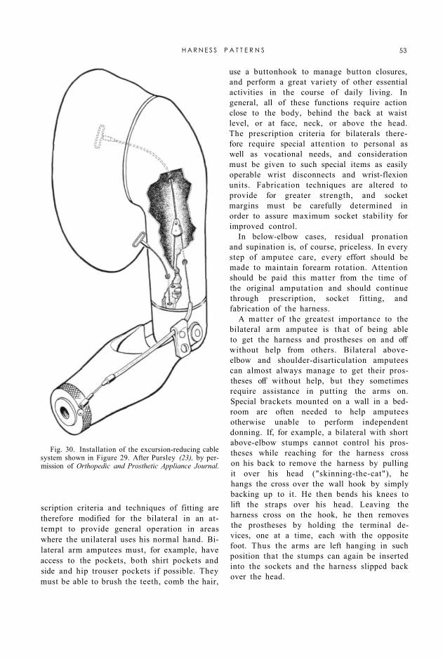
scription criteria and techniques of fitting are therefore modified for the bilateral in an attempt to provide general operation in areas where the unilateral uses his normal hand. Bilateral arm amputees must, for example, have access to the pockets, both shirt pockets and side and hip trouser pockets if possible. They must be able to brush the teeth, comb the hair,
use a buttonhook to manage button closures, and perform a great variety of other essential activities in the course of daily living. In general, all of these functions require action close to the body, behind the back at waist level, or at face, neck, or above the head. The prescription criteria for bilaterals therefore require special attention to personal as well as vocational needs, and consideration must be given to such special items as easily operable wrist disconnects and wrist-flexion units. Fabrication techniques are altered to provide for greater strength, and socket margins must be carefully determined in order to assure maximum socket stability for improved control.
In below-elbow cases, residual pronation and supination is, of course, priceless. In every step of amputee care, every effort should be made to maintain forearm rotation. Attention should be paid this matter from the time of the original amputation and should continue through prescription, socket fitting, and fabrication of the harness.
A matter of the greatest importance to the bilateral arm amputee is that of being able to get the harness and prostheses on and off without help from others. Bilateral above-elbow and shoulder-disarticulation amputees can almost always manage to get their prostheses off without help, but they sometimes require assistance in putting the arms on. Special brackets mounted on a wall in a bedroom are often needed to help amputees otherwise unable to perform independent donning. If, for example, a bilateral with short above-elbow stumps cannot control his prostheses while reaching for the harness cross on his back to remove the harness by pulling it over his head ("skinning-the-cat"), he hangs the cross over the wall hook by simply backing up to it. He then bends his knees to lift the straps over his head. Leaving the harness cross on the hook, he then removes the prostheses by holding the terminal devices, one at a time, each with the opposite foot. Thus the arms are left hanging in such position that the stumps can again be inserted into the sockets and the harness slipped back over the head.
Fig. 30. Installation of the excursion-reducing cable system shown in Figure 29. After Pursley (23), by permission of Orthopedic and Prosthetic Appliance Journal.
H A R N E S S P A T T E R N S 53
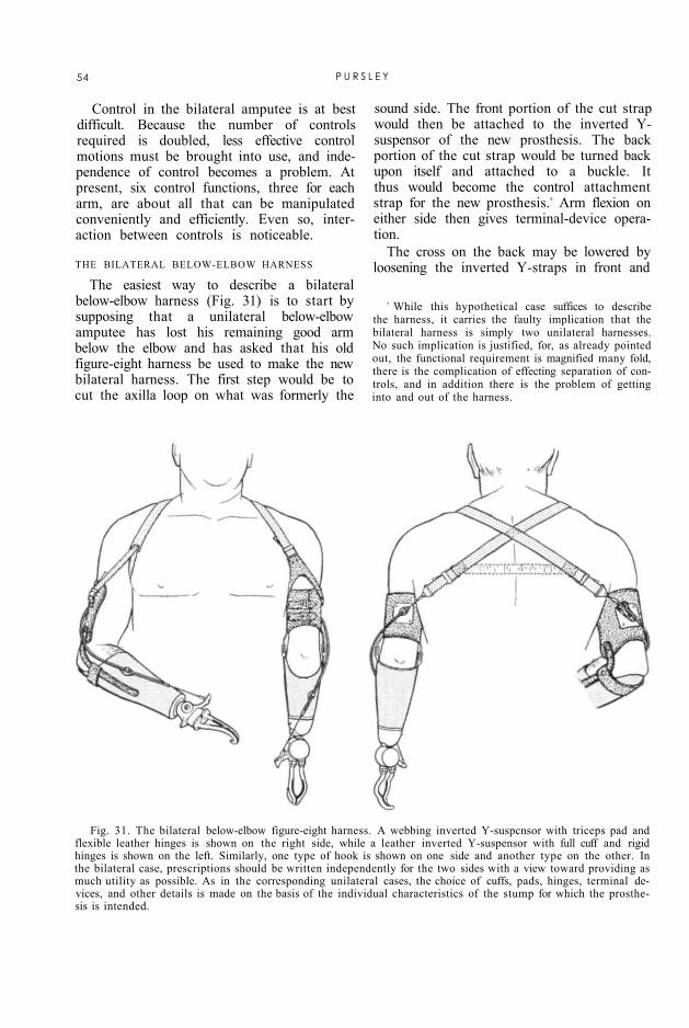
Fig. 31. The bilateral below-elbow figure-eight harness. A webbing inverted Y-suspcnsor with triceps pad and flexible leather hinges is shown on the right side, while a leather inverted Y-suspensor with full cuff and rigid hinges is shown on the left. Similarly, one type of hook is shown on one side and another type on the other. In the bilateral case, prescriptions should be written independently for the two sides with a view toward providing as much utility as possible. As in the corresponding unilateral cases, the choice of cuffs, pads, hinges, terminal devices, and other details is made on the basis of the individual characteristics of the stump for which the prosthesis is intended.
Control in the bilateral amputee is at best difficult. Because the number of controls required is doubled, less effective control motions must be brought into use, and independence of control becomes a problem. At present, six control functions, three for each arm, are about all that can be manipulated conveniently and efficiently. Even so, interaction between controls is noticeable.
THE BILATERAL BELOW-ELBOW HARNESS
9 While this hypothetical case suffices to describe the harness, it carries the faulty implication that the bilateral harness is simply two unilateral harnesses. No such implication is justified, for, as already pointed out, the functional requirement is magnified many fold, there is the complication of effecting separation of controls, and in addition there is the problem of getting into and out of the harness.
The easiest way to describe a bilateral below-elbow harness (Fig. 31) is to start by supposing that a unilateral below-elbow amputee has lost his remaining good arm below the elbow and has asked that his old figure-eight harness be used to make the new bilateral harness. The first step would be to cut the axilla loop on what was formerly the
sound side. The front portion of the cut strap would then be attached to the inverted Y-suspensor of the new prosthesis. The back portion of the cut strap would be turned back upon itself and attached to a buckle. It thus would become the control attachment strap for the new prosthesis.9 Arm flexion on either side then gives terminal-device operation.
The cross on the back may be lowered by loosening the inverted Y-straps in front and
54 P U R S L E Y
taking up the slack in the control attachment straps. The reverse procedure moves the cross up. Should the cross be too far to one side, it may be moved horizontally by loosening the inverted Y-strap and control attachment strap on that side and taking up the slack on the opposite side.
An important consideration is the choice of materials best suited to the individual case. In Figure 31, the right Y-suspensor is made of vinyon, while the left is made of leather. If the amputee finds that getting the harness on and off is a major problem, then the tendency of leather to maintain its shape makes it easier to slip the stumps through the suspensors. If excessive perspiration is a problem, then vinyon tape may be more suitable.
Although the combination of one leather and one vinyon Y-suspensor is shown in Figure 31 primarily to suggest the two possibilities, it is not inconceivable to consider the arrangement for actual use. In the bilateral below-elbow cases, the choice of cuffs and hinges is made independently for each side on the basis of such factors as stump length, muscular tone, and elbow mobility. In some cases, it might be well to consider using flexible hinges on one side to encourage the use of residual pronation-supination while applying full cuff and rigid hinges on the other to provide stability. A bilateral so fitted would thus have the added versatility provided by an enhanced function of one kind in one arm and an enhanced function of a different kind in the other.
In Figure 31, a wrist-flexion unit is installed on the left prosthesis. Although in exceptional cases the bilateral fitting of wrist-flexion units might be desirable, ordinarily only one flexion device is necessary. When only one wrist-flexion unit is used, amputee preference, or simply prosthetic dominance of one extremity over the other, is probably the best criterion for determining the side to which wrist flexion should be applied.
THE BILATERAL ABOVE-ELBOW HARNESS
The unilateral below-elbow figure-eight harness has been adapted for bilateral above-elbow cases as well as for the bilateral below-
elbow amputee. It is essentially the same as for the below-elbow cases but with added suspensory harness and means of operating the elbow locks. A typical pattern is illustrated in Figure 32. If allowance is made for the increased need for function in the bilateral case, then fabrication of the bilateral above-elbow harness is similar to that of the unilateral above-elbow figure-eight pattern. Use is made of the same methods of harness adjustment as in adjusting the harness for the below-elbow bilateral.
Before attempting the fabrication of the bilateral above-elbow harness, the harness-maker must understand the above-elbow figure-eight harness for unilaterals. He should then discuss with his patient any special vocational or personal activities requiring modification of harness design. When the harness is completed, the prosthetist should make it a point to follow up progress in training to make sure that the bilateral amputee can soon become self-sufficient in all necessary activities. If attention is paid to these few details, and if each bilateral amputee is treated as an individual problem, surprisingly good results may be obtained in practically all bilateral cases.
THE BILATERAL SHOULDER-DISARTICULATION HARNESS
Because the bilateral shoulder disarticulation and the bilateral above-elbow/shoulder combination represent comparatively rare and highly specialized instances of upper-extremity amputation, it has thus far not been possible to establish any set harness pattern for these cases. Although in general the bilateral shoulder-disarticulation harness is a sort of combination of two shoulder-disarticulation harnesses for the unilateral, every amputee requiring such harness must have meticulous attention to details in the individual case. In any event, it is obvious that, in the bilateral shoulder-disarticulation amputee, the goal of the prosthetist is to obtain as much function as possible regardless of necessary deviations from ordinary practice. Although experience with extreme cases of this kind has to date been limited, the Case Study at the University of California at Los Angeles
H A R N E S S P A T T E R N S 55

(page 61) has accumulated some useful information. At present, the knowledge gained at UCLA probably offers the most important guide for management of the individual bilateral shoulder-disarticulation case.
Fig. 32. The bilateral above-elbow figure-eight harness. As in the bilateral below-elbow case, here too the choice of components for the two sides is made independently with regard for individual stump characteristics and with the intention of providing as much useful function as possible.
CONCLUSION
To the student of the art of harnessing upper-extremity prostheses, it will now have become perfectly plain that here, as in almost every other published source, the harness designs presented are principally those applicable to the comparatively young, healthy, adult male amputee. Included, furthermore, are only those systems for which there has been accumulated enough clinical evidence to prove their validity for use with presently available arm components. Noticeably missing are special patterns and fabrication techniques for the very young, for the very old, for the debilitated, for the special cases involving
other complicating handicaps, and, with two exceptions, for the female.
The reason for this situation lies in the fact that, inspired as it was by the desire to aid the veteran returning from the wars, the Artificial Limb Program, sponsored by the Veterans Administration and the Department of Defense, has quite naturally placed emphasis upon the type of amputee to be expected from the battlefield. But it is not fully appreciated by the general public that there are produced annually from disease or accidents—in the home, on the highway, in the factory—many, many more amputees than are ever produced in military campaigns. Such causes of amputation play no favorites with age or sex.
Fortunately, the basic principles involved in the harnessing of the adult male are more or less fully applicable to the juvenile amputee. Recently, for example, an armamentarium chart defining child amputee types and offering
56 P U R S L E Y

suggestions for prescription for children of age three and a half to ten years has been prepared under the auspices of the Michigan Crippled Children Commission (18). Two columns of this reference document are devoted to "harness type" and "control type" respectively. Except for the omission of the below-elbow dual control and of the above-elbow and shoul-der-disarticulation triple controls, at every level of arm amputation in the child the recommended harness and control systems are identical with those used for the corresponding level in the adult male. The only significant modifications are concerned with the use of 1/2-in. instead of 1-in. webbing, according to the size of the child, and with the twofold recommendation that the harness be worn over a T-shirt and that the younger children be provided with two harnesses, one to be worn while the other is laundered. Since in general young children do not possess harnessable forces as large as are usually to be had in the adult, the unit stresses produced by the narrower webbing are acceptable to the small child, and hence, following the rule of minimum permissible harness in all cases, it is obviously advisable to use the 1/2-in. material whenever it can serve the small fry satisfactorily. The need of children generally for a frequent change of clothing deserves no further comment here.
In any event, it will be recalled that some twelve-year-olds are actually larger and stronger than some adults, and consequently the determining factor in any given child is his own particular size, which in turn determines whether 1/2-in. or 1-in. material will provide the more comfort. Other features of harness fabrication for children are essentially the same as for adult harnessing.
As for the adult female, generally the harness for the adult male is applicable, with the exceptions that the chest-strap designs usually are not desirable and that commonly more emphasis is placed on cosmesis. Most women, for example, prefer to have a choice of wearing "V" necklines instead of being restricted to Peter Pan collars or other high necklines. The figure-eight harness pattern is adequate for both above- and below-elbow female amputees. In high-above-elbow cases and
shoulder disarticulations, the patterns of Figures 27 and 28 usually serve satisfactorily.
Elderly amputees, amputees with multiple limb losses, and those with additional complications such as blindness or deafness all present such highly specialized problems that no single harness pattern can be more than partially satisfactory in all cases. Some evidence seems to indicate that there may even be an age limit beyond which most individuals begin to feel that bothering with an artificial arm at all is no longer worth the effort. But no really scientific evaluation has yet been made of the needs of the aged amputee. Circumstances in the individual case must therefore dictate the course to be taken. As in the case of children, some geriatric patients are healthy, strong. and dynamic; others are ailing, feeble, or lethargic. In the elderly amputee, therefore, as in all special cases, personal factors prevent the recommendation of any generalized harnessing system.
In the two illustrations of typical harnessing for bilateral arm amputees (Figs. 31 and 32), the subjects are shown as having amputations at approximately the same level on the two sides. In actual clinical practice, of course, bilateral arm cases present all possible combinations of above- and below-elbow amputations. In all such cases, the problem of devising suitable harnessing combinations presents a special challenge to the prosthetics clinic team. Similarly, in the case of amputations complicated by other mental or physical handicaps, special assessment of the individual patient must be made to determine, first of all, whether use of a prosthesis is actually feasible and, if so, what if any departures from conventional harness patterns are indicated. In all such unusual instances, the considered judgment of the clinic team is indispensable in the development of a specialized harness pattern suited to the needs and abilities of the individual concerned,
It may now be reiterated that, even in the so-called "standard" cases, it does not suffice to supply a "standard" harness. The reference chart of Table 1 is appended here only for the convenience of the clinic team in selecting the basic kind of harness applicable to any given case. It is, in the end, the responsibility of the
H A R N E S S P A T T E R N S 57

58 PU
RSLE
Y

prosthetist to see that the details are properly custom-matched to the wearer and that, after adequate amputee training, the harness chosen actually fulfills satisfactorily the needs of the wearer for whom it was intended. Less meticulous avenues of approach lead ultimately to failure.
Finally, cognizance should be taken of the understandable circumstance that the harness patterns presented here have all been developed specifically for use with existing mechanical devices. The above-elbow and shoulder-disarticulation systems—the dual-control figure-eight, the dual-control chest-strap, and the triple-control patterns—have, for example, all been designed around existing elbows. Because heretofore the art of harnessing has lagged behind the development of arm components, it has been necessary in recent years to design the harness systems to fit the mechanical parts rather than vice versa. A more logical arrangement would have been first to analyze the available body control motions, to design the harness for maximum utilization of these motions in the least awkward way, and then to design the other parts of the prosthesis in such a manner as to be operable by control patterns best suited to amputee characteristics. Future research in harnessing can be expected to influence redesign of desirable operational characteristics of the mechanical devices now available and to encourage the development of wholly new and improved arm components.
ACKNOWLEDGMENT
With the exception of the photographs and of Figure 12, the illustrations appearing in this article are the work of George Rybczynski, free-lance artist of Washington, D. C.
L I T E R A T U R E C I T E D
1. Alldredge, Rufus H. , and Eugene F. Murphy , Prosthetics research and the amputation surgeon, Artificial Limbs, 1(3):4 (September 1954).
2 . Alldredge, Rufus H. , Verne T. I nman , H y m a n Jampol , Eugene F. M u r p h y , and August W. Spittler, The techniques of cineplasty, Chapter 3 in Klopsteg and Wilson's Human limbs and their substitutes. McGraw-Hil l , New York, 1954
3 . Army Prosthet ics Research Labora tory , Walter Reed Army Medical Center , Technical Report 5424, Comparison of UCLA and APRL cable transmission systems for B.E. biceps cineplasty arm, 21 June 1954.
Army Prosthet ics Research Labora tory , Walter Reed Army Medical Center , Technical Repor t 5526, Shop instructions for cable and sheave equalizer systems (below-elbow cineplasty APRL), 8 August 1955.
5. Carlyle, Lester , Artificial arm checkout procedures, Artificial Limbs , J a n u a r y 1954. p. 25.
6. Carlyle, Lester, Fitting the artificial arm, Chapter 19 in Klopsteg and Wilson's Human limbs and their substitutes, McGraw-Hil l , New York, 1954.
7. Carnes, W. T. , U. S. P a t e n t 1,046,966, December 10, 1912.
8. Carnes, W. T., U. S. P a t e n t 1,046,967, December 10, 1912.
9. Carnes, W. T, U. S. P a t e n t 1,402,476, J anua ry 3, 1922.
10. DeFries , Myron G., and Fred Leonard, Bacteriostatic nylon films, Applied Microbiology, 3(4):238 (1955).
11. Fletcher, Maur ice J., and A. Benne t t Wilson, Jr . , New developments in artificial arms, Chap te r 10 in Klopsteg and Wilson's Human limbs and their substitutes, McGraw-Hil l , New York, 1954.
12. Hitchcock, William E., Abduction for shoulder dis-articulation prosthesis, Or thop , & Pros. Appl. J., September 1955. p. 23.
13. I nman , Verne T. , and H. J. Rals ton, The mechanics of voluntary miscle, Chap te r 11 in Klopsteg and Wilson's Human limbs and their substitutes, McGraw-Hil l , New York, 1954.
14. Kessler, H e n r y H. , Cineplasty, Charles C Thomas , Springfield, Ill., 1947.
15. Langdale-Kelham, R D. , and George Perkins, Amputations and artificial limbs, Oxford University Press, London: H u m p h r e y Milford, 1944.
16. Leonard, Fred, T. B. Blevins, W S. Wright , and M. G. DeFries , Nylon-coated leather, Ind Eng. Chem., 45:773 (1953).
17. Marks , George E. , A treatise on Marks' patent artificial limbs with rubber hands and feet, A. A. Marks , New York, 1889.
18. M a r y Free Bed Children's Hospi ta l and Orthopedic Center , Grand Rapids , Mich. , Child amputee types and suggestions for prosthetic prescription, 3 1/2 years to 10 years (a char t ) , 1955.
19. Moun t , George E. , and Raymond E. Bernberg, A preliminary comparison of perception undet cineplastic and harness prostheses, Am. J. Psychol., LXI I (1 ) : 106 (1949 ) .
20. New York University, Pros thet ic Devices Study, Commit tee on Above-Elbow Harness [Hector Kay, Chairman] , Repor t of conference, The above-elbow figure-eight harness—a guide to procedures and principles, September 23, 1954.
21. Nor throp Aircraft, Inc. , Hawthorne , Calif., Subcontractor ' s Final Repor t to the Commit tee on Artificial Limbs, Nat iona l Research Council, Artificial arm and leg research and development, February 1951. Sections 1.6.1 and 1.6.1.1, p. 92.
22. Northwestern Technological Institute, Evanston, Ill., Subcontractor's Final Report to the Committee on Artificial Limbs, National Research Council, A review of the literature, patents, and manufactured items concerned with artificial legs, arm harnesses, hand, and hook; mechanical testing of artificial legs, 1947.
H A R N E S S P A T T E R N S 59

23. Pursley, Robert J., Harness for shoulder disarticulation amputees, Orthop. & Pros. Appl. J., March 1955. p. 15.
24. Spittler, August W., and Maurice J. Fletcher, Technique of cineplastic surgery and prosthetic appliances for cineplasty, Am. Acad. Orthopaedic Surgeons Instructional Course Lectures, Volume X, Edwards, Ann Arbor, Mich., 1953.
25. Taylor, Craig L., The biomechanics of the normal and of the amputated upper extremity, Chapter 7 in
Klopsteg and Wilson's Human limbs and their substitutes, McGraw-Hill, New York, 1954.
26. Taylor, Craig L., Control design and prosthetic adaptations to biceps and pectoral cineplasty, Chapter 12 in Klopsteg and Wilson's Human limbs and their substitutes, McGraw-Hill, New York, 1954.
27. University of California (Los Angeles), Department of Engineering, Manual of upper extremity prosthetics, R. Deane Aylesworth, ed., 1952.
28. U. S. Naval Hospital, Oakland, Calif., Artificial Limb Department, Blueprint 811, Carpometacarpal {harness controlled) prosthesis, September 22, 1952.
29. Wilson, A. Bennett, Jr., and Robert J. Pursley, Fitting the wrist disarticulation case, Orthop. & Pros. Appl. J., September 1952. p. 17.
60 P U R S L E Y

Some Experience in Harnessing Extreme Arm Cases
CRAIG L TAYLOR, Ph.D.1
1 Professor of Engineering, University of California, Los Angeles; member, Advisory Committee on Artificial Limbs, National Research Council, and of the Technical Committee on Prosthetics, ACAL, NRC.
recent developments in shoulder prostheses, including that for complete removal of the shoulder girdle, it is possible to fit all upper-extremity amputees with useful arm substitutes. But of course it does not follow that all patients with high amputations can obtain from the available harnessing resources a uniformly good level of prosthetic function. It is appropriate to review present experience with such cases in order to establish realistic guides for the fitter. Although there is only a limited number of upper-extremity amputees with multiple amputations or with amputations at very high levels, the UCLA Case Study (1) has accumulated a sufficient number to make tentative conclusions possible.
Limitation in the potentialities of shoulder harness begins with the unilateral shoulder case of the disarticulation type. Unilateral humeral-neck amputees with an intact shoulder girdle have, in every case known, been able to manage the shoulder dual control, and with any of several elbow-lock arrangements they have been able to carry out all of the operations of the prosthesis. Further unilateral shoulder losses, or losses of both shoulders at various levels, entail such impairment of harnessable shoulder mobility that it is impossible to attain the operating effectiveness ordinarily to be expected from the major prosthetic controls. A review of several types of fittings and the results obtained indicates the nature of these limitations.
UNILATERAL SHOULDER AMPUTEES
In the unilateral shoulder amputee, limitation begins with the disarticulation because the leverage on the amputated side is then so reduced that biscapular shrug no longer gives the necessary excursion. With most men of average to large build, however, the results usually are satisfactory (Table 1). In the case of M.W., pelvic control was required. T.M., a large and broad-shouldered man, obtained good function despite large, but not complete, clavicle and scapula losses. With the fore-quarter case, P.H., the sound shoulder could not manage the full control, and the functional regain was decidedly marginal.
BILATERAL ABOVE-ELBOW/SHOULDER COMBINATIONS
No case of bilateral humeral-neck amputation has thus far come to notice, but the bilateral above-elbow/shoulder combination is comparatively frequent. Five cases of this type can be cited. All save one are at least moderately successful. The unsuccessful case, C.B., has a number of stump complications that have prevented a satisfactory result. Otherwise, good operation, one prosthesis at a time, is provided by harnessing modifications in which the elements of the shoulder-disarticulation harness from one side and of the figure-eight from the other are combined. It should be noted that in all these cases both shoulder girdles are intact, and there is in addition one humeral stump. Hence, shrug and arm-flexion controls can be managed normally.
The first case of this type, L.S., is a young man, age 29, with a right above-elbow stump of 10 in. and a humeral-neck amputation on the left side. The musculature and mobility
61
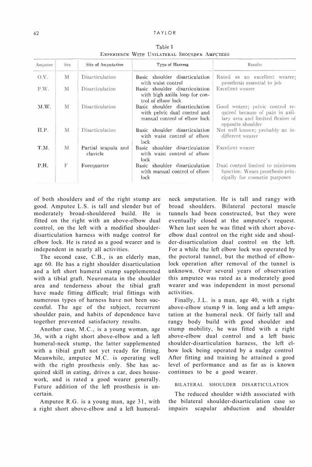
of both shoulders and of the right stump are good. Amputee L.S. is tall and slender but of moderately broad-shouldered build. He is fitted on the right with an above-elbow dual control, on the left with a modified shoulder-disarticulation harness with nudge control for elbow lock. He is rated as a good wearer and is independent in nearly all activities.
The second case, C.B., is an elderly man, age 60. He has a right shoulder disarticulation and a left short humeral stump supplemented with a tibial graft. Neuromata in the shoulder area and tenderness about the tibial graft have made fitting difficult; trial fittings with numerous types of harness have not been successful. The age of the subject, recurrent shoulder pain, and habits of dependence have together prevented satisfactory results.
Another case, M.C., is a young woman, age 36, with a right short above-elbow and a left humeral-neck stump, the latter supplemented with a tibial graft not yet ready for fitting. Meanwhile, amputee M.C. is operating well with the right prosthesis only. She has acquired skill in eating, drives a car, does housework, and is rated a good wearer generally. Future addition of the left prosthesis is uncertain.
Amputee R.G. is a young man, age 31, with a right short above-elbow and a left humeral-
neck amputation. He is tall and rangy with broad shoulders. Bilateral pectoral muscle tunnels had been constructed, but they were eventually closed at the amputee's request. When last seen he was fitted with short above-elbow dual control on the right side and shoul-der-disarticulation dual control on the left. For a while the left elbow lock was operated by the pectoral tunnel, but the method of elbow-lock operation after removal of the tunnel is unknown. Over several years of observation this amputee was rated as a moderately good wearer and was independent in most personal activities.
Finally, J.L. is a man, age 40, with a right above-elbow stump 9 in. long and a left amputation at the humeral neck. Of fairly tall and rangy body build with good shoulder and stump mobility, he was fitted with a right above-elbow dual control and a left basic shoulder-disarticulation harness, the left elbow lock being operated by a nudge control After fitting and training he attained a good level of performance and as far as is known continues to be a good wearer.
BILATERAL SHOULDER DISARTICULATION
The reduced shoulder width associated with the bilateral shoulder-disarticulation case so impairs scapular abduction and shoulder
62 T A Y L O R

flexion that complete control of the prostheses is not possible. Full operation of the terminal device at elbow angles above 90 deg. cannot be managed with the dual control, and a lower level of operation must be accepted. The pelvic control remains a possibility, but this expedient has so many disadvantages of inconvenience, awkwardness, and discomfort that few if any amputees accept it for continuous use. Shoulder control can at best be unilateral only.
Nevertheless, an acceptable level of function may result. For example, J.G. is an elderly man, age 63, with bilateral shoulder disarticulations. Of medium build and with rounded chest, he has to date been completely dependent on help from others. Fitting and care have been sporadic because of infrequent visits to the laboratory. He last was fitted unilaterally with a right prosthesis and a reaction cap on the left shoulder. Thus far the fit has been promising. At the last visit he had managed eating and other activities.
With the congenital anomalies, amelia and phocomelia, control functions usually are considered as being the same as those for the shoulder-disarticulation case. Shoulder girdles are narrow because of the absence of humeral heads or owing to loose and nonarticulated rudimentary elements, so that basic shoulder control may not be adequate for bilateral function. In phocomelia, with both forearm and hand or only hand elements, additional help may often be obtained for secondary controls such as elbow-lock operation. In any event, these congenitals early develop "manipulation" with the feet, and these capabilities have not been matched, so far as is known, by any upper-extremity prosthesis.
LITERATURE CITED
1. Gottlieb, M. S., Final report of the UCLA upper extremity amputee case study, Department of Engineering, University of California (Los Angeles), in preparation 1955.
SOME E X T R E M E A R M CASES 63

Digest of Major Activities of the
Artificial Limb Program
Panel on Prosthetics Research and Development Meetings of the Panel on Prosthetics Re
search and Development were held in Washington June 25 and 27. They were preceded by meetings of the various subcommittees on June 23 and 24. Reports of the subcommittee meetings and of the Panel sessions have been prepared and distributed.
Primary consideration was given to the formulation of plans for the lower-extremity pilot school at Oakland and to subsequent courses in lower-extremity prosthetics. Plans for the pilot school were initially devised by the Subcommittee on Education under the chairmanship of Dr. Clinton L. Compere, of the VARO Orthopedic and Prosthetic Appliance Clinic Team, Chicago.
Also of interest was the appointment of a new editorial board for ARTIFICIAL LIMBS, to be responsible for the content planning beginning with the Spring 1956 issue. The new-board consists of Prof. Howard D. Eberhart, of the School of Engineering, University of California, Berkeley; Dr. Verne T. Inman, of the School of Medicine, University of California, San Francisco; Dr. Fred Leonard, of the Army Prosthetics Research Laboratory, Walter Reed Army Medical Center, Washington; Dr. Eugene F. Murphy, of the Prosthetic and Sensory Aids Service, Veterans Administration, New York; and Dr. Craig L. Taylor, of the School of Engineering, University of California, Los Angeles.
The next meeting of the Panel and subcommittees will be held in Washington December 1 through 5.
Resignation of Dr. Thorndike
Dr. Augustus Thorndike, Acting Director of the Prosthetic and Sensory Aids Service of the Veterans Administration since PSAS
DR. THORNDIKE
was organized in July 1948, resigned that position on July 1 to devote more time to his increasing responsibilities as chief surgeon to the Department of Hygiene, Harvard University. Because of the many demands for his services, Dr. Thorndike has always worked with the VA on a part-time basis, and he has
agreed to remain as consultant to the Chief Medical Director for another year.
In addition to his other duties, Dr. Thorndike is President of the Bay State Medical Rehabilitation Clinic, of the Perkins Institution, and of the Massachusetts School for the Blind, and he participates generally in other
fields of medicine. Always active in the area of medical literature, he is the author of several books and of many journal articles on surgical problems, especially those associated with trauma.
Much of the progress attained in all aspects of prosthetic and sensory aids is attributable directly to Dr. Thorndike's guidance. He effected marked economies in services to disabled veterans; and better devices, improved services, and educational programs have been provided under his leadership. Among his outstanding contributions to amputee rehabilitation was the formulation of the clinic-team concept. His plan brought together, as a team, surgeons, prosthetists, therapists, and engineers. By cooperating closely with one another, members of these professions have brought new understanding to the problems of amputee management. The clinic-team approach, once limited to facilities of the Veterans Administration, now is a widely accepted technique outside the VA.
Promotion for Dr. Stewart
Dr. Robert E. Stewart, formerly Assistant Director of the VA's Prosthetic and Sensory Aids Service, has been appointed Director of PSAS to succeed Dr. Augustus Thorndike. He assumed his new duties on July 1.
64
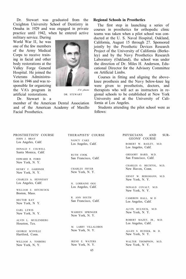
Dr. Stewart was graduated from the Creighton University School of Dentistry in Omaha in 1929 and was engaged in private practice until 1942, when he entered active military service. During World War II, he was one of the few members of the Army Medical Corps to receive training in facial and other body restorations at the Valley Forge General Hospital. He joined the Veterans Administration in 1946 and was responsible for organizing the VA's program in artificial restorations.
Dr. Stewart is a member of the American Dental Association and of the American Academy of Maxillo Facial Prosthetics.
-VA photo
DR. STEWART
Regional Schools in Prosthetics The first step in launching a series of
courses in prosthetics for orthopedic clinic teams was taken when a pilot school was conducted at the U. S. Naval Hospital, Oakland, California, August 15 through 27. Sponsored jointly by the Prosthetic Devices Research Project of the University of California (Berkeley) and by the Navy Prosthetics Research Laboratory (Oakland), the school was under the direction of Dr. Miles H. Anderson, Educational Director for the Advisory Committee on Artificial Limbs.
Courses in fitting and aligning the above-knee prosthesis and the Navy below-knee leg were given to prosthetists, doctors, and therapists who will act as instructors in regional schools to be established at New York University and at the University of California at Los Angeles.
Students attending the pilot school were as follows:
PROSTHETISTS' COURSE JOHN J. BRAY Los Angeles, Calif.
DONALD F. COLWELL Santa Monica, Calif.
EDWARD R. FORD New York, N. Y.
HENRY F. GARDNER New York, N. Y.
CHARLES A. HENNESSY Los Angeles, Calif.
WILLIAM E. HITCHCOCK Boston, Mass.
HECTOR KAY New York, N Y.
EARL LEWIS New York, N. Y.
ALVIN L. MUILENBERG Houston, Tex.
GEORGE SCOVILLE Hartford, Conn.
WILLIAM A. TOSBERG New York, N, Y.
THERAPISTS' COURSE NANCY CAKE Los Angeles, Calif.
RUTH COOK San Francisco, Calif.
CHARLES FRYER New York, N. Y.
H. LORRAINE OGG Los Angeles, Calif.
R. ANN SOUTH San Francisco, Calif.
WARREN SPRINGER New York, N. Y.
M. LARRY VILLALOBOS New York, N. Y.
IRENE E. WATERS New York, N. Y.
PHYSICIANS AND SURGEONS' COURSE
ROBERT W. BAILEY, M.D. Los Angeles, Calif.
GREGORY BARD, M.D. San Francisco, Calif.
CHARLES O. BECHTOL, M.D, New Haven, Conn.
ERNST W. BERGMANN, M.D. New York, N. Y.
DONALD COVALT, M.D. New York, N. Y.
CAMERON HALL, M D Los Angeles, Calif.
ALVIN HULNICK, M.D. New York, N. Y.
ROBERT MAZET, JR., M.D. Los Angeles, Calif.
ALLEN S. RUSSEK, M. D. New York, N Y.
WALTER THOMPSON, M.D, New York, N Y.
65

The week of August 29 was spent by the students in reviewing the course given during the previous two weeks and in organizing the curriculum to be used in the regional schools.
The first course at NYU is scheduled for early in February 1956, the first at UCLA for early in March.
Studies at PTDL
One of the interesting projects that has been under way at the Prosthetic Testing and Development Laboratory of the Veterans Administration, New York City, has been concerned with the study of stump socks. To date, two reports have been issued. The first (17-2 PTDL) reviews the experience of sock wearers. The second (17-3 PTDL) summarizes the results of a study of the quality of stump socks as related specifically to washing and durability.
In cooperation with the Orthopedic Shop of the New York Regional Office, PTDL currently is conducting a comprehensive study of repairs of orthopedic and prosthetic appliances. The investigation has two aims—to determine the chief causes of failure and to find a way of controlling or eliminating those causes that have been a common source of difficulty and thus responsible for frequent need for repair.
Attention is also being concentrated on the development of arm braces for cases of paralysis involving the upper extremity. This investigation is being conducted by the Prosthetic Testing and Development Laboratory with the assistance of other staff members of the Research and Development Division, Prosthetic and Sensory Aids Service. In several ways the design of arm braces follows the principles outlined by the upper-extremity prosthetics program, and consequently these two areas often supplement each other.
Personnel Changes at PSAS
The Prosthetic and Sensory Aids Service of the Veterans Administration has announced with regret the resignation of Leo Larsen for reasons of health. Harold Kesselman has been appointed to the position of Materials Engineer which was established recently in the Prosthetic Testing and Development Laboratory.
PSAS Training Courses
The Prosthetic and Sensory Aids Service of the Veterans Administration has announced plans for a series of technical training courses for its Prosthetic Representatives. These specialists are in charge of Prosthetic and Sensory Aids Units in VA facilities throughout the country and serve as technical and administrative advisers to the professional medical staff regarding all appliances.
The technical training courses will each be of two weeks' duration, the first being scheduled for New York City beginning January 9, 1956.
New VA Film
A new 16-mm. color and sound motion picture, U pper-Extremily Prosthetic Principles, has recently been prepared by the Veterans Administration. Presented in the film are examples of government-supported research in upper-extremity prosthetics that has led to a revised set of principles governing the improved design, construction, and fit of artificial arms. Included also is a systematic description of the functions lost at different levels of amputation and of the principles involved in effective replacement by means of arm prostheses. An armamentarium board and other items, among them the latest available devices and components, are reviewed in detail. Running time, 25 minutes.
The new film is available on loan to interested organizations. Requests should be addressed to the Central Office Film Library, Veterans Administration, Washington 25, D. C.
OALMA Regional Meetings
The United States is divided into eleven regional councils of OALMA members. These groups hold regular meetings to discuss technical subjects and management problems, and orthopedic surgeons and others interested in prosthetics are frequently guests.
Since early last spring (ARTIFICIAL LIMBS, May 1955, p. 98), the New England Council, which forms Region I of OALMA, has continued to hold monthly sessions at the Rehabilitation Center in Boston. Dr. William E. Kenney, Medical Director of the Cerebral
66

Palsy Training Center, Fall River, Mass., was guest speaker at the March meeting. His paper, Improving Relationships between Or-thotists, Prosthetists, and Orthopedists, appeared in the Orthopedic and Prosthetic Appliance Journal for September 1955. Reprints are available without cost.
The New England Council also has organized a free library for the benefit of employees of artificial-limb and brace establishments in New England. This project is under the direction of Howard Mooney, as librarian, with the assistance of John Buckley of Providence. Anyone interested in contributing reports, reprints, or books to this collection should write to Mr. Mooney in care of the Boston Artificial Limb Company, 69 Canal Street, Boston, Mass.
Region II of OALMA (New York and New Jersey areas) has announced its 1956 Technical Seminar to be held at the Hotel Bilt-more, New York City, April 27 and 28. Copies of the program may be obtained from OALMA National Headquarters, 411 Associations Building, Washington 6, D. C.
OALMA-ABC Exhibits
The Orthopedic Appliance and Limb Manufacturers Association and the American Board for Certification have initiated a program of exhibits at scientific and professional meetings in order to acquaint these groups with new developments in prosthetics and with the certification movement for better-trained prosthetists. In the last year, the Association has had displays at the scientific sections of two meetings of the American Medical Association, the Clinic Session at Miami, November 29 through December 2, 1954 (ARTIFICIAL LIMBS, January 1955, p. 66), and the 104th Annual Meeting at Atlantic City, June 6 through 10. The exhibit at Atlantic City was in the section on orthopedic surgery. It was described in the official program in these words: "There has been a revolutionary change in the training, attitudes, and skills of the men who only a few years ago were known as and limited as brace fitters; limb fitters. The exhibit points out the changes to the physician and outlines his recourse in the event of unethical or unsatisfactory service."
The Association plans to exhibit at not less than four national conventions each year. The schedule for the year ahead includes the exposition on Employment of the Physically Handicapped, Chicago, November 28 through 30, 1955; the American Academy of Orthopaedic Surgeons, Chicago, January 28 through February 2, 1956; the American Congress of Physical Medicine, Atlantic City, September 9 through 14, 1956; and the American Medical Association, Seattle, November 27 through 30, 1956.
Other special exhibits are to be arranged whenever the opportunity of reaching an important group is afforded the Association.
Congress of Physical Medicine and Rehabilitation
The sessions of the American Congress of Physical Medicine and Rehabilitation at Detroit, August 28 through September 2, revealed a growing interest in prosthetics on the part of physiatrists, as shown both in the papers delivered before the Congress and in the displays making up the Scientific Exhibits. Among the papers given, and scheduled for publication in the Archives of Physical Medicine and Rehabilitation, were Hand Disabilities, by Dr. Harriet E. Gillette, Director of the Physical Medicine and Rehabilitation Clinic at Atlanta, Georgia, and The Amputee in Industry—A Follow-Up Study, by Dr. Charles Long II , Chief of the Division of Physical Medicine and Rehabilitation at the Henry Ford Hospital in Detroit.
The exhibits included one by the American Board for Certification (see cut, page 68) describing "Certification in the Artificial Limb and Brace Field: A Service to the Physiatrist and His Patients." "Armless Children" was the subject of a display on cineplasty by Dr. Earl F. Hoerner of the Kessler Institute. The booth of the Michigan Crippled Children Commission, arranged by Dr. Carleton Dean, used a number of manikins to display prosthetic appliances designed for children.
Technical films shown to the Congress included Training of the Bilateral Arm Amputee, Bobby McClellan—Bilateral Leg Amputee, and
67

—Spencer, Crosse Ile Mich
ABC EXHIBIT AT PM&R CONGRESS—This group of volunteers helped to man the booth and to answer questions at the display of the American Board for Certification during the 1955 Congress of Physical Medicine and Rehabilitation at the Hotel Statler in Detroit the week of August 28. Left to right are Vernon Murka, certified prosthetist and orthotist of Dayton, Ohio; Dan H. Strelnick, Chief of Physical Therapy at the Veterans Administration Center, Wood, Wisconsin; and Marvin L. Sturtz, certified prosthetist and orthotist, Edward F. Schmitt, President of the E. H. Rowley Company, and Durward R. Coon, certified prosthetist and orthotist, all of Detroit. The manikin at right was on loan from the Michigan Crippled Children Commission.
Use of an Hydraulically Operative Assistive Device (Sabre Arm) in the Rehabilitation of a Severely Disabled Polio Patient with Two Flail Upper Extremities.
Advisory Council for ABC The eleven hundred certified prosthetists
and orthotists of the United States maintain a council of seventy members to serve as an advisory body to the American Board for Certification of the Prosthetic and Orthopedic Appliance Industry, Inc. Each council member serves also as a one-man information center for apprentice prosthetists and orthotists in his own area. In the 1955 elections concluded September 1, the new members chosen were as follows: W. T. Adams, Little Rock, Ark.; Vernon Allen, Spokane, Wash.; Al Amsterdam, Syracuse, N. Y.; Joseph C.
Aveni, Boston, Mass.; L. B. Barghausen, Columbus, Ohio; Richard Bidwell, Milwaukee, Wis.; D. R. Bohnen-kamp, Omaha, Neb.; James M. Bonds, Knoxville, Tenn.; Wil-more Bremer, Jacksonville, Fla.; Wayne E. Brooks, Portland, Ore.; Oscar J. Bruce, Roanoke, Va.; John F. Buckley, Providence, R. I.; Lenard C. Ceder, Tacoma, Wash.; Cooper C. Collins, Little Rock, Ark.; D. R. Coon, Detroit, Mich.; John G. Cranford, Richmond, Va.; Theron M. Davidson, Indianapolis, Ind.; Cedric D. Denison, Baltimore, Md.; E. P. Dillon, Kansas City, Mo.; Kenneth C. Dodd, Los Angeles, Calif.; Fred Eschen, New York, N. Y.; Alexander Finlay, Milwaukee, Wis.; Wilbur L. Floyd, Charleston, S. C; Lester R. Fulton, St.
Louis, Mo.; Joseph P. Giacinto, Detroit, Mich.; Alfons R. Glaubitz, Elizabethtown, Pa.; A. L. Godbey, Miami, Fla.; R. W. Goldsby, Mobile, Ala.; Everett F. Haines, Davenport, Iowa; Herbert Hanger, New York, N. Y.; Erich Hanicke, Kansas City, Mo.; W. Frank Harmon, Atlanta, Ga.; Stanley E. Hedges, Indianapolis, Ind.; Emil Houk, Chicago, Ill.; Jerome Kessler, Newark, N. J.; George I. Kinman, Toronto, Ont.; F. L. Lake, Oklahoma City, Okla.; Mat t Laurence, Oakland, Calif.; Paul E. Leimkuehler, Cleveland, Ohio; Richard M. Locke, Birmingham, Ala.; Joseph H. Martino, Boston, Mass.; William C. McCall, St. Petersburg, Fla.; Walter B. McCarty, Philadelphia, Pa.; David C. McGraw, Shreveport, La.; Clarence E. Medcalf, Minneapolis, Minn.; Alvin R. Muilenburg, Houston, Tex.; Vernon Murka,
68

Dayton, Ohio; Chester Nelson, Minneapolis, Minn.; K. B. Nelson, Pittsburgh, Pa.; Fred R. Norton, Texarkana, Tex.; Earl W. Odell, Portland, Ore.; Ben Pecorella, Buffalo, N. Y.; Laurence Porten, Pittsburgh, Pa.; Nunzio Pulizzi, Williamsport, Pa.; Charles Ross, Washington, D. C; Alberta May Rule, Montreal, Que.; Walter Schoene, Chicago, Ill.: James D. Shope, Shreveport, La.; Ralph Snell, Nashville, Tenn.; Roy Snelson, Los Angeles, Calif.; Edward W. Snygg, San Francisco, Calif.; Joseph A. Spievak, Youngs-town, Ohio; A. H. Starkey, Hartford, Conn.; Michael Stone, Denver, Colo.; George R. Thornton, Denver, Colo.; Nicholas Treuhaft, Miami, Fla.; Myron T. Vail, St. Louis, Mo.; R. N. Witt, Gonzales, Tex.; Charles W. Wright, Philadelphia, Pa.; Calvin Yardley, Newark, N. J.
Symposium at AAAS
Challenging problems involved in the restoration of function to individuals with paralysis or amputations will be discussed by leading authorities as part of the 122nd meeting of the American Association for the Advancement of Science in Atlanta during the forthcoming Christmas week. At morning and afternoon sessions in the Municipal Auditorium on December 30, new developments in orthopedic braces and in artificial limbs will be discussed from the medical, engineering, and economic viewpoints.
Of particular novelty will be presentations of the little-known economic aspects of the brace and artificial-limb industries, according to Dr. Eugene F. Murphy, Chief of the Research and Development Division of VA's Prosthetic and Sensory Aids Service, who is organizer of the symposium. Other papers, in discussing the social and economic productivity of patients requiring braces or artificial limbs, will consider the many benefits for the individual and the financial as well as the humane values earned by society on investments in rehabilitation.
The morning session will be under the chairmanship of Dr. Thomas P. Goodwyn, Medical Administrative Consultant to the Georgia Division of Vocational Rehabilitation. Dr. Robert L. Bennett, Medical Director of the Georgia Warm Springs Foundation,
will open the meeting with a discussion of the advances made in the bracing of persons with severe arm paralysis. Numerous assistive devices used by such people in performing their daily activities will be demonstrated.
Miss Grace Marie Freymann, psychologist with the Georgia Warm Springs Foundation, will analyze the results of a follow-up study of polio patients dealing with the economic status attained, family assistance required, employer and family attitudes, and the need for repairs and changes in devices. Donald Dabelstein, Assistant Director, Office of Vocational Rehabilitation, Department of Health, Education, and Welfare, will present data regarding the economic outcomes of vocational rehabilitation of the orthopedically disabled based on the experience of various state divisions of vocational rehabilitation.
E. B. Whitten, Executive Director of the National Rehabilitation Association, will preside at the afternoon session. It will begin with a discussion of the economic aspects of the artificial-limb industry by McCarthy Hanger, Jr., President, J. E. Hanger, Inc., St. Louis, and currently President of the Orthopedic Appliance and Limb Manufacturers Association. Included in Mr. Hanger's talk will be a discussion of the nature of the limbfitting problem, the size and geographical distribution of limb shops, the historical development of the industry and its present methods, its participation in the Artificial Limb Program, and its progress toward professional status. A similar discussion of the economics of the bracemaking and fitting industry will be offered by W. Frank Harmon of the Atlanta Brace Shop and First Vice-President of OALMA.
A paper on new developments in bracing will be presented by Dr. Augustus Thorndike, consultant to the Veterans Administration and chief surgeon to the Department of Hygiene at Harvard University; Dr. Murphy, engineer in charge of VA's research on prosthetic and sensory aids; and Anthony Staros, Chief of VA's Prosthetic Testing and Development Laboratory. Machine and clinical tests of new plastic bushings to reduce wear will be described, as will also a novel brace for low back injuries and the application of new principles to braces for paralyzed arms.
69