Advantages of CT in 3D Scanning of Industrial Parts — December 2008 Vol. 1, No. 3 Advantages of CT...
5
18 — December 2008 Vol. 1, No. 3 Advantages of CT in 3D Scanning of Industrial Parts Industrial CT (computerized tomography) uses a series of 2-dimensional images taken at specific intervals around the entire sample. Basically any type of industrial CT system uses three principal components: an X-ray tube, an X-ray detector, and a rotational stage. Everything is enclosed within a radiation shielding steel/lead/steel cabinet that typically ranges between four and 10 feet cubed. This allows use of the system in a public environment without any additional safety concerns. Micro computed tomography (micro-CT) is primarily the same as standard CT except it uses a micro focus tube instead of a traditional tube. A micro-CT scan yields resolutions in microns because the focal spot of a micro focus tube is only a few microns in size. For comparison, micro-CT resolution is about 100 times better than the best CAT scan in the medical field. High quality industrial X-ray detectors used for CT are typically a new generation amorphous silicon flat panel area detector. They offer a very high sensitivity, resolution and bit depth. The resulting 2D X-ray images are very clear and the contrast is unparalleled. Capturing the Image A modern high-end CT scan consists of taking several 2D X-ray images around the object, preferably covering 360 degrees (complete rotation). CT systems typically acquire between 360 images (one image every degree) and 3600 images (one image every 0.1 degree) depending on the final desired resolution. Each image is between three to 10 megapixels and is also averaged and filtered to reduce noise. The 2D digital images taken during this step are saved directly into a single folder, which will be used in the next step of the CT process. Figure 1 - General princi- ple of a modern industrial CT scan Julien Noel, North Star Imaging Inc C omputed tomography (CT) has come along way since its public inception in 1972. The rapid improvement of computer technology and increased capabilities of CT scanning have definitely gone hand in hand. This increase in capability has led to CT scans being used more often and in more ways than ever before. The use of CT in the industrial nondestructive testing (NDT) field is one example that has grown tremendously over the past few years. This article presents a project that used 3D CT reconstruction of a casting to measure and compare against CAD models. ©2008 3D Scanning Technologies Magazine. All rights reserved. No material contained herein may be printed or transmitted by any means electronic or mechanical without prior written permission of the publisher Contact [email protected]
Transcript of Advantages of CT in 3D Scanning of Industrial Parts — December 2008 Vol. 1, No. 3 Advantages of CT...
18 — December 2008 Vol. 1, No. 3
Advantages of CT in 3D Scanning of Industrial Parts
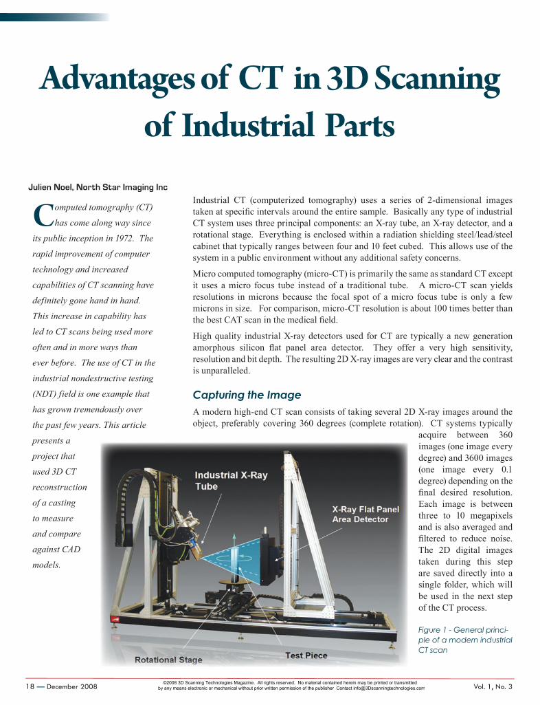
Industrial CT (computerized tomography) uses a series of 2-dimensional images taken at specific intervals around the entire sample. Basically any type of industrial CT system uses three principal components: an X-ray tube, an X-ray detector, and a rotational stage. Everything is enclosed within a radiation shielding steel/lead/steel cabinet that typically ranges between four and 10 feet cubed. This allows use of the system in a public environment without any additional safety concerns.
Micro computed tomography (micro-CT) is primarily the same as standard CT except it uses a micro focus tube instead of a traditional tube. A micro-CT scan yields resolutions in microns because the focal spot of a micro focus tube is only a few microns in size. For comparison, micro-CT resolution is about 100 times better than the best CAT scan in the medical field.
High quality industrial X-ray detectors used for CT are typically a new generation amorphous silicon flat panel area detector. They offer a very high sensitivity, resolution and bit depth. The resulting 2D X-ray images are very clear and the contrast is unparalleled.
Capturing the ImageA modern high-end CT scan consists of taking several 2D X-ray images around the object, preferably covering 360 degrees (complete rotation). CT systems typically
acquire between 360 images (one image every degree) and 3600 images (one image every 0.1 degree) depending on the final desired resolution. Each image is between three to 10 megapixels and is also averaged and filtered to reduce noise. The 2D digital images taken during this step are saved directly into a single folder, which will be used in the next step of the CT process.
Figure 1 - General princi-ple of a modern industrial CT scan
Julien Noel, North Star Imaging Inc
Computed tomography (CT)
has come along way since
its public inception in 1972. The
rapid improvement of computer
technology and increased
capabilities of CT scanning have
definitely gone hand in hand.
This increase in capability has
led to CT scans being used more
often and in more ways than
ever before. The use of CT in the
industrial nondestructive testing
(NDT) field is one example that
has grown tremendously over
the past few years. This article
presents a
project that
used 3D CT
reconstruction
of a casting
to measure
and compare
against CAD
models.
NORTHstar_KS_crx.indd 18 11/21/08 5:20:07 PM
©2008 3D Scanning Technologies Magazine. All rights reserved. No material contained herein may be printed or transmitted by any means electronic or mechanical without prior written permission of the publisher Contact [email protected]
www.3DScaNNiNgTechNologieS.com December 2008 — 19
Reconstruction and VisualizationOnce the acquisition process of the CT scan is completed, CT calibration and CT reconstruction algorithms are used to reconstruct the 3D CT volume. These 3D images are made of voxels (three-dimensional pixels), and with the use of visualization software the 3D volume can be manipulated in real time. Because of this it is possible to slice through anywhere inside the object, inspect and look for defects, take accurate measurements, reconstruct a surface model and so forth.
Industrial CT technology is improving very quickly. While a few single CT slices would take hours to generate years ago, it is now possible to reconstruct complete 3D models with billions of voxels in just seconds. This opens the door for numerous new applications like 3D reverse engineering, rapid prototyping, 3D metrology and more. In that regard, industrial CT has become a very competitive technology for 3D scanning.
The principal benefit of using 3D CT for scanning or digitization is that we obtain a complete model with both external and internal surfaces of an object without destroying it. Moreover, CT works with any surface, shape, color or material, up to a certain density and/or thickness penetrable with X-rays. Generally, a modern start-to-finish CT scan can be as fast as a few seconds or take
longer than an hour, depending on the resolution requirements and size and density of the object. Overall, the resolution is excellent both internally and externally, which in turn can fulfill virtually any designer’s needs.
To illustrate the benefits and capabilities of CT, North Star Imaging, a developer, manufacturer and supplier of NDT equipment and services, worked with the company Twin City Die Casting and performed CT scans on an aluminum die cast.
Twin City Die Casting Evaluates 3D CTTwin City Die Castings Company (TCDC) was estab-lished in 1919 in Minneapolis, Minnesota and is cur-rently a full-service supplier of precision aluminum, magnesium and zinc die-castings. TCDC contacted North Star Imaging’s (NSI) Inspection Services Group (ISG) to evaluate 3D CT reconstruction as an alterna-tive to 3D laser scanning.
A 3D CT reconstruction appeared to be a good fit to fulfill the goals of this project for many reasons. CT scans nondestructively provide excellent resolution
internally and externally, which allows for measurement on surfaces both inside and outside an object. Also, due to the penetration of X-rays, CT scans are unaffected by certain object characteristics such as dark, reflective or transparent surfaces and shaded zones on the item that can cause difficulty with other 3D scanning methods. Furthermore, 3D CT reconstruction models can be directly compared to CAD models and other CT models in order to display differences or commonalities in measurements, densities, voids and so forth.
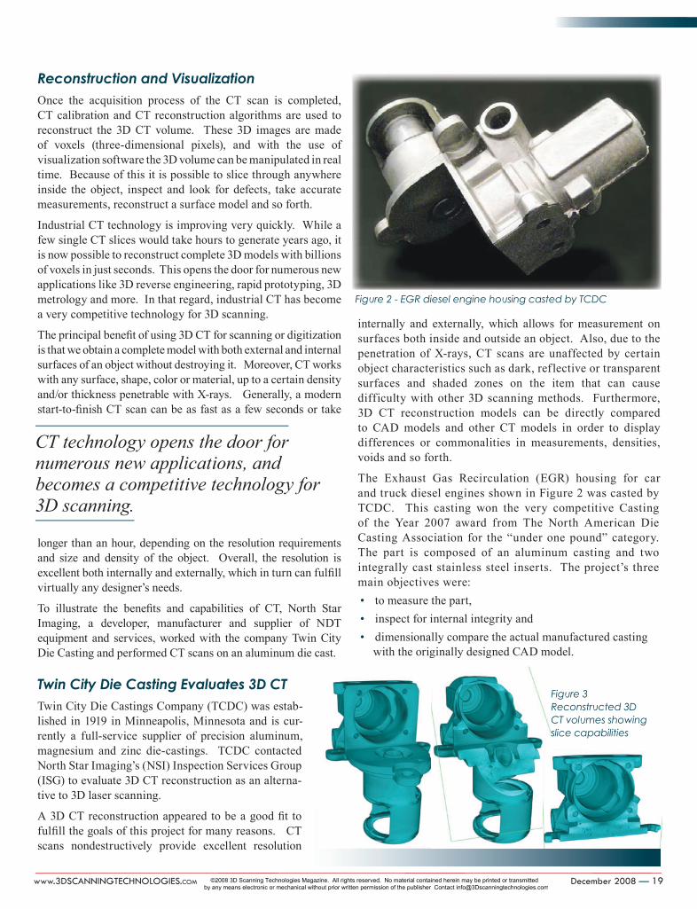
The Exhaust Gas Recirculation (EGR) housing for car and truck diesel engines shown in Figure 2 was casted by TCDC. This casting won the very competitive Casting of the Year 2007 award from The North American Die Casting Association for the “under one pound” category. The part is composed of an aluminum casting and two integrally cast stainless steel inserts. The project’s three main objectives were:
to measure the part, • inspect for internal integrity and • dimensionally compare the actual manufactured casting • with the originally designed CAD model.
CT technology opens the door for numerous new applications, and becomes a competitive technology for 3D scanning.
Figure 2 - EGR diesel engine housing casted by TCDC
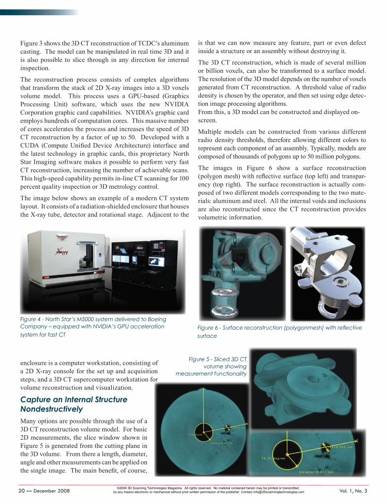
Figure 3 Reconstructed 3D CT volumes showing slice capabilities
NORTHstar_KS_crx.indd 19 11/21/08 5:20:09 PM
©2008 3D Scanning Technologies Magazine. All rights reserved. No material contained herein may be printed or transmitted by any means electronic or mechanical without prior written permission of the publisher Contact [email protected]
20 — December 2008 Vol. 1, No. 3
Figure 3 shows the 3D CT reconstruction of TCDC’s aluminum casting. The model can be manipulated in real time 3D and it is also possible to slice through in any direction for internal inspection.
The reconstruction process consists of complex algorithms that transform the stack of 2D X-ray images into a 3D voxels volume model. This process uses a GPU-based (Graphics Processing Unit) software, which uses the new NVIDIA Corporation graphic card capabilities. NVIDIA’s graphic card employs hundreds of computation cores. This massive number of cores accelerates the process and increases the speed of 3D CT reconstruction by a factor of up to 50. Developed with a CUDA (Compute Unified Device Architecture) interface and the latest technology in graphic cards, this proprietary North Star Imaging software makes it possible to perform very fast CT reconstruction, increasing the number of achievable scans. This high-speed capability permits in-line CT scanning for 100 percent quality inspection or 3D metrology control.
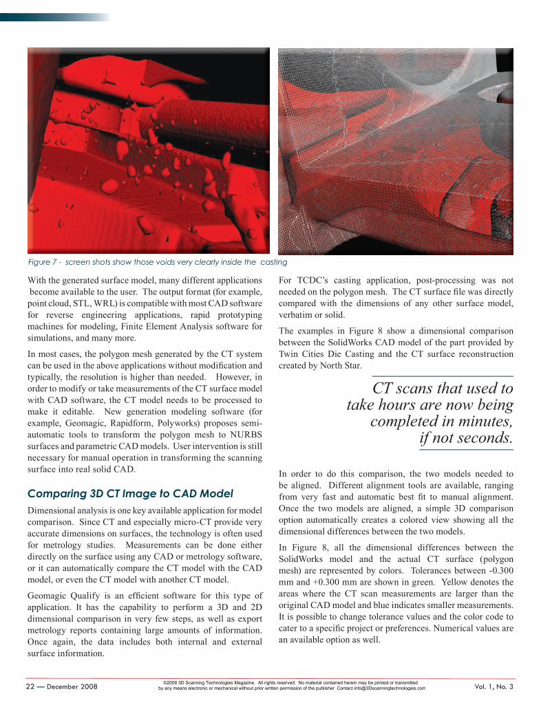
The image below shows an example of a modern CT system layout. It consists of a radiation-shielded enclosure that houses the X-ray tube, detector and rotational stage. Adjacent to the
enclosure is a computer workstation, consisting of a 2D X-ray console for the set up and acquisition steps, and a 3D CT supercomputer workstation for volume reconstruction and visualization.
Capture an Internal Structure NondestructivelyMany options are possible through the use of a 3D CT reconstruction volume model. For basic 2D measurements, the slice window shown in Figure 5 is generated from the cutting plane in the 3D volume. From there a length, diameter, angle and other measurements can be applied on the single image. The main benefit, of course,
is that we can now measure any feature, part or even defect inside a structure or an assembly without destroying it.
The 3D CT reconstruction, which is made of several million or billion voxels, can also be transformed to a surface model. The resolution of the 3D model depends on the number of voxels generated from CT reconstruction. A threshold value of radio density is chosen by the operator, and then set using edge detec-tion image processing algorithms. From this, a 3D model can be constructed and displayed on-screen.
Multiple models can be constructed from various different radio density thresholds, therefore allowing different colors to represent each component of an assembly. Typically, models are composed of thousands of polygons up to 50 million polygons.
The images in Figure 6 show a surface reconstruction (polygon mesh) with reflective surface (top left) and transpar-ency (top right). The surface reconstruction is actually com-posed of two different models corresponding to the two mate-rials: aluminum and steel. All the internal voids and inclusions are also reconstructed since the CT reconstruction provides volumetric information.
steps, and a 3D CT supercomputer workstation for
Figure 5 - Sliced 3D CT volume showing
measurement functionality
Figure 6 - Surface reconstruction (polygonmesh) with reflective surface
Figure 4 - North Star’s M5000 system delivered to Boeing Company – equipped with NVIDIA’s GPU acceleration system for fast CT
NORTHstar_KS_crx.indd 20 11/21/08 5:20:12 PM
©2008 3D Scanning Technologies Magazine. All rights reserved. No material contained herein may be printed or transmitted by any means electronic or mechanical without prior written permission of the publisher Contact [email protected]
22 — December 2008 Vol. 1, No. 3
With the generated surface model, many different applications become available to the user. The output format (for example, point cloud, STL, WRL) is compatible with most CAD software for reverse engineering applications, rapid prototyping machines for modeling, Finite Element Analysis software for simulations, and many more.
In most cases, the polygon mesh generated by the CT system can be used in the above applications without modification and typically, the resolution is higher than needed. However, in order to modify or take measurements of the CT surface model with CAD software, the CT model needs to be processed to make it editable. New generation modeling software (for example, Geomagic, Rapidform, Polyworks) proposes semi-automatic tools to transform the polygon mesh to NURBS surfaces and parametric CAD models. User intervention is still necessary for manual operation in transforming the scanning surface into real solid CAD.
Comparing 3D CT Image to CAD ModelDimensional analysis is one key available application for model comparison. Since CT and especially micro-CT provide very accurate dimensions on surfaces, the technology is often used for metrology studies. Measurements can be done either directly on the surface using any CAD or metrology software, or it can automatically compare the CT model with the CAD model, or even the CT model with another CT model.
Geomagic Qualify is an efficient software for this type of application. It has the capability to perform a 3D and 2D dimensional comparison in very few steps, as well as export metrology reports containing large amounts of information. Once again, the data includes both internal and external surface information.
For TCDC’s casting application, post-processing was not needed on the polygon mesh. The CT surface file was directly compared with the dimensions of any other surface model, verbatim or solid.
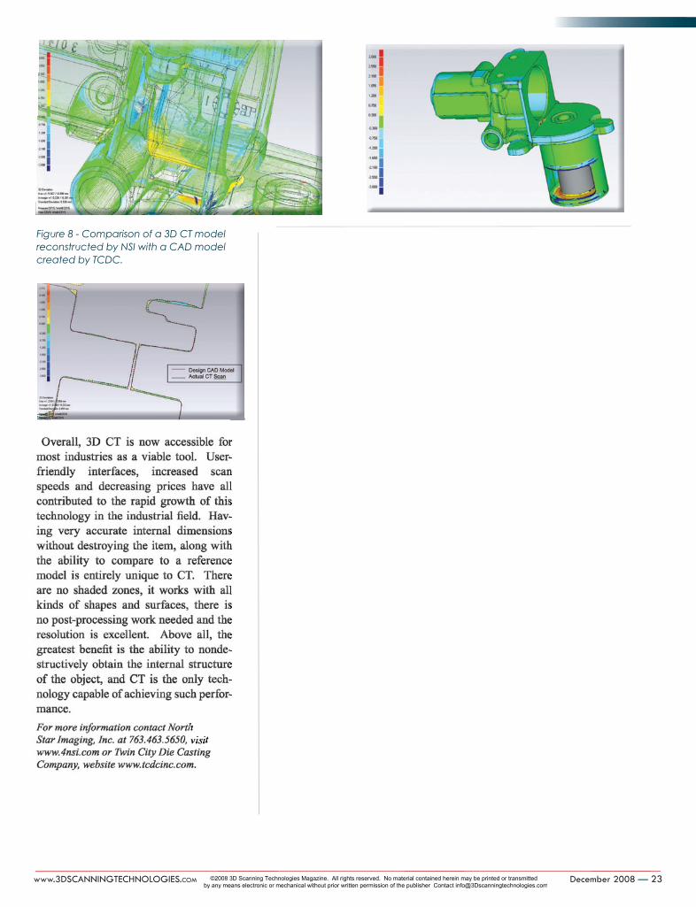
The examples in Figure 8 show a dimensional comparison between the SolidWorks CAD model of the part provided by Twin Cities Die Casting and the CT surface reconstruction created by North Star.
In order to do this comparison, the two models needed to be aligned. Different alignment tools are available, ranging from very fast and automatic best fit to manual alignment. Once the two models are aligned, a simple 3D comparison option automatically creates a colored view showing all the dimensional differences between the two models.
In Figure 8, all the dimensional differences between the SolidWorks model and the actual CT surface (polygon mesh) are represented by colors. Tolerances between -0.300 mm and +0.300 mm are shown in green. Yellow denotes the areas where the CT scan measurements are larger than the original CAD model and blue indicates smaller measurements. It is possible to change tolerance values and the color code to cater to a specific project or preferences. Numerical values are an available option as well.
Figure 7 - screen shots show those voids very clearly inside the casting
CT scans that used to take hours are now being
completed in minutes, if not seconds.
NORTHstar_KS_crx.indd 22 11/21/08 5:20:13 PM
©2008 3D Scanning Technologies Magazine. All rights reserved. No material contained herein may be printed or transmitted by any means electronic or mechanical without prior written permission of the publisher Contact [email protected]
www.3DScaNNiNgTechNologieS.com December 2008 — 23
Figure 8 - Comparison of a 3D CT model reconstructed by NSI with a CAD model created by TCDC.
NORTHstar_KS_crx.indd 23 11/21/08 5:20:15 PM
©2008 3D Scanning Technologies Magazine. All rights reserved. No material contained herein may be printed or transmitted by any means electronic or mechanical without prior written permission of the publisher Contact [email protected]