Advances in the acoustics of ow ducts and mufflers · Advances in the acoustics of ow ducts and...
16
Siidhand, Vol. 15, Part 2, September 1990, pp. 57-72. 0 Printed in India. Advances in the acoustics of ow ducts and mufflers M L MUNJAL Department of Mechanical Engineering, Indian Institute of Science, Bangalore 560 012, India MS received 14 May 1990 Abstract. This review paper deals with advances made in the last two decades in the acoustics of flow ducts for heating, ventilation and air-conditioning (HVAC) systems and engine mumers. The context, concepts, methods used and .results have been highlighted. Frequency-domain one-dimensional analysis of reflective mumers has been emphasized because of its basic importance and wide application. Finally, problems needing further research have been identified. Keywords. Acoustics; mufflers; noise control; engines; HVAC systems; duct acoustics. Ua 1. Introduction " * Exhaust noise of automotive engines is the main component of the noise pollution of the urban environment. With the ever-increasing population density of vehicles on the road, this has become an important area of research and development. Most U of the advances in the theory of acoustic filters and exhaust mufflers have come about in the last three decades, and the author of this article has been active in this area for over two decades. For a monograph on the acoustics of ducts and mufflers see Munjal (1987a). This article, following the monograph in format, briefly reviews the b work done by him independently and jointly with his colleagues and students, and relates it to the state-of-the-art. Finally, further problems awaiting solution are identified for future research in the area. 2. Frequency-domain one-dimensional analysis of reflective mufflers s An acoustic filter is a one-dimensional dynamical system comprising distributed and lumped elements, analogous to the electrical filters used in the transmission line theory. While electro-acoustic analogies were known for a long time (see, for example, Olson 1966), the analogic electrical circuits for engine exhaust mufflers were made use of for the first time by Sreenath & Munjal(1970). The state variables of acoustic pressure and mass velocity were described as analogous to electromotive force (voltage)
Transcript of Advances in the acoustics of ow ducts and mufflers · Advances in the acoustics of ow ducts and...
Siidhand, Vol. 15, Part 2, September 1990, pp. 57-72. 0 Printed in India.
Advances in the acoustics of ow ducts and mufflers
M L MUNJAL
Department of Mechanical Engineering, Indian Institute of Science, Bangalore 560 012, India
MS received 14 May 1990
Abstract. This review paper deals with advances made in the last two decades in the acoustics of flow ducts for heating, ventilation and air-conditioning (HVAC) systems and engine mumers. The context, concepts, methods used and .results have been highlighted. Frequency-domain one-dimensional analysis of reflective mumers has been emphasized because of its basic importance and wide application. Finally, problems needing further research have been identified.
Keywords. Acoustics; mufflers; noise control; engines; HVAC systems; duct acoustics.
Ua 1. Introduction " *
Exhaust noise of automotive engines is the main component of the noise pollution of the urban environment. With the ever-increasing population density of vehicles on the road, this has become an important area of research and development. Most
U
of the advances in the theory of acoustic filters and exhaust mufflers have come about in the last three decades, and the author of this article has been active in this area for over two decades. For a monograph on the acoustics of ducts and mufflers see Munjal (1987a). This article, following the monograph in format, briefly reviews the
b
work done by him independently and jointly with his colleagues and students, and relates it to the state-of-the-art. Finally, further problems awaiting solution are identified for future research in the area.
2. Frequency-domain one-dimensional analysis of reflective mufflers
s An acoustic filter is a one-dimensional dynamical system comprising distributed and lumped elements, analogous to the electrical filters used in the transmission line theory. While electro-acoustic analogies were known for a long time (see, for example, Olson 1966), the analogic electrical circuits for engine exhaust mufflers were made use of for the first time by Sreenath & Munjal(1970). The state variables of acoustic pressure and mass velocity were described as analogous to electromotive force (voltage)
5 8 M L Munjal
and current, and due consideration was given to the radiation impedance Zo (of the atmosphere at the tail-pipe end), and source characteristics p, and Z,, analogous to the load impedance, open circuit voltage and internal impedance of the source, respectively.
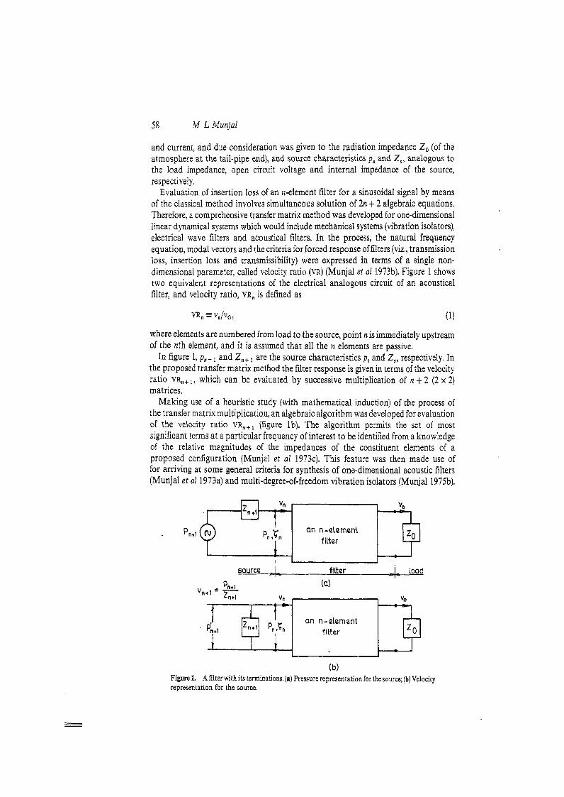
Evaluation of insertion loss of an 11-element filter for a sinusoidai signal by means of the classical method involves simultaneous solution of 2n t 2 algebraic equations. Therefore, a comprehensive transfer matrix method was developed for one-dimensional linear dynamical systems which would include mechanical systems (vibration isolators), electrical wave filters and acoustical filters. In the process, the natural frequency equation, modal vectors and the criteria for forced response of filters (viz., transmission loss, insertion loss and transmissibility) were expressed in terms of a single non- dimensional parameter, called velocity ratio (VR) (Munjal et al 1973b). Figure 1 shows two equivalent representations of the electrical analogous circuit of an acoustical filter, and velocity ratio, VR, is defined as
where elements are numbered from load to the source, point n is immediately upstream of the nth element, and it is assumed that all the n elements are passive.
In figure 1, p, , , and Z , , , are the source characteristics p, and Z,, respectively. In the proposed transfer matrix method the filter response is given in terms of the velocity ratio VR,,,, which can be evaluated by successive multiplication of n t 2 (2 x 2) matrices.
Making use of a heuristic study (with mathematical induction) of the process of the transfer matrix multiplication, an algebraic algorithm was developed for evaluation of the velocity ratio VR,,, (figure Ib). The algorithm permits the set of most significant terms at a particular frequency of interest to be identified from a knowledge of the relative magnitudes of the impedances of the constituent elements of a proposed configuration (Munjal et al 1973~). This feature was then made use of for arriving at some general criteria for synthesis of one-dimensional acoustic filters (Munjal et a1 1973a) and multi-degree-of-freedom vibration isolators (Munjal 1975b).
Pn+l an n-element
an n-element ttt Z"+I P,Jn f i r r r+ I 1
(b) Figure 1. A filter with its terminations. (a) Pressure representation for the source; @) Velocity representation for the source.
Advances in the acoustics of flow ducts and muflers 5 9
The transfer matrices used in the aforesaid articles assumed plane wave propagation in a stationary inviscid medium. The problem of wave propagation in a viscous medium involves a coupling of radial and axial components of acoustic particle velocity in the Navier-Stokes equations as well as the continuity equation. This was solved to obtain the analytical expressions for the acoustic pressure attenuation constant, (complex) wave number, and (complex) characteristic impedance. These results were then applied to analyse waves in branched pipes of the hydraulic brake system excited by periodic pumping (Kant et a1 1974).
In the case of engine muflers, waves propagate in a moving medium. In order to account for the convective effect of mean flow, a new set of state variables, convective pressure p, and convective mass velocity vc were defined to replace the classical variables of acoustic pressure p and acoustic mass velocity, v. It turned out that the two sets of variables are related linearly to each other as follows:
and the acoustic power flux in a moving medium is given by (Munjal 1975a)
which is analogous to that for the stationary medium
where * denotes the complex conjugate. Through the convective state variables, the velocity ratio cum transfer matrix method was extended to the evaluation of a mumer with mean Row. This was significantly superior to the earlier method (Alfredson & Davies 1970. 1971) involving simultaneous solution of a large number of algebraic equations with complex coefficients.
Unlike in a dissipative muffler, the energy leaving a reflective mufler a t the radiation end is equal to what enters at the source end. It has been shown analytically (Munjal 1980) that a reflective mufller works by reducing the resistive component Rn of the load impedance seen by the source, as compared to R,,,, the atmospheric impedance that the source would see in the absence of the muffler, the insertion loss (IL) of which is given by (Munjal 1977)
where subscripts 1 and 2 denote "without the muffler" and "with the mumer", respectively. Incidentally, for a stationary medium with the exhaust pipe diameter being equal to the tail-;ipe diameter (figure 2), (6) would simplify to (Munjal et a1 1973b)
Evaluation of the velocity ratio V R , , ~ + ~ ( ~ VCvn+ l/Vc,o) calls for successive multi- plication of the convective transfer matrices of elements 0 to n + 1,
60 IM L Munjal
point polnt point point n n- 1 1 0
radiation impedance Za
dement 0
muffler ____CI
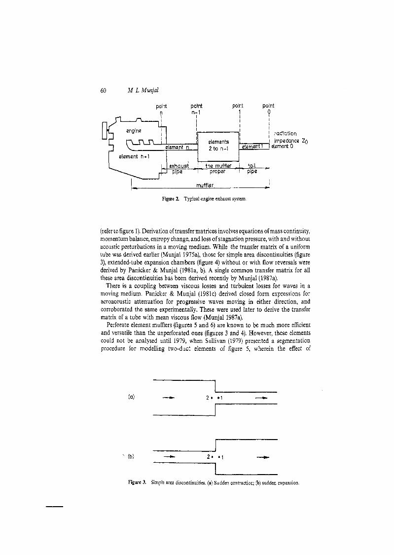
Figure 2. Typical engine exhaust system.
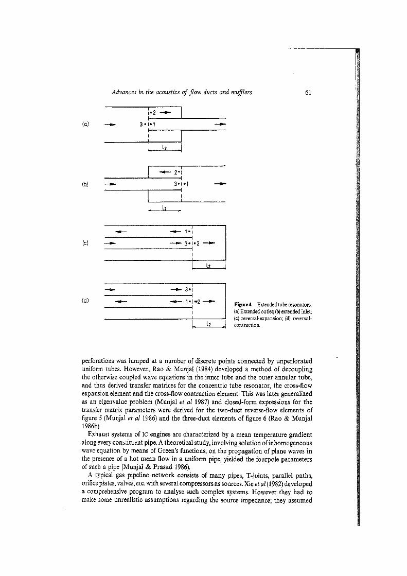
(refer to figure 1). Derivation of transfer matrices involves equations of mass continuity, momentum balar~ce, entropy change, and loss of stagnation pressure, with and without acoustic perturbations in a moving medium. While the transfer matrix of a uniform tube was derived earlier (Munjal 1975a), those for simple area discontinuities (figure 3), extended-tube expansion chambers (figure 4) without or with flow reversals were derived by Panicker & Munjal (l98la, b). A single common transfer matrix for all these area discontinuities has been derived recently by Munjal (1987aj.
There is a coupling between viscous losses and turbulent losses for waves in a moving medium. Panicker & Munjal (1981~) derived closed form expressions for aeroacoustic attenuation for progressive waves moving in either direction, and corroborated the same experimentally. These were used later to derive the transfer matrix of a tube with mean viscous flow (Munjal 1987a).
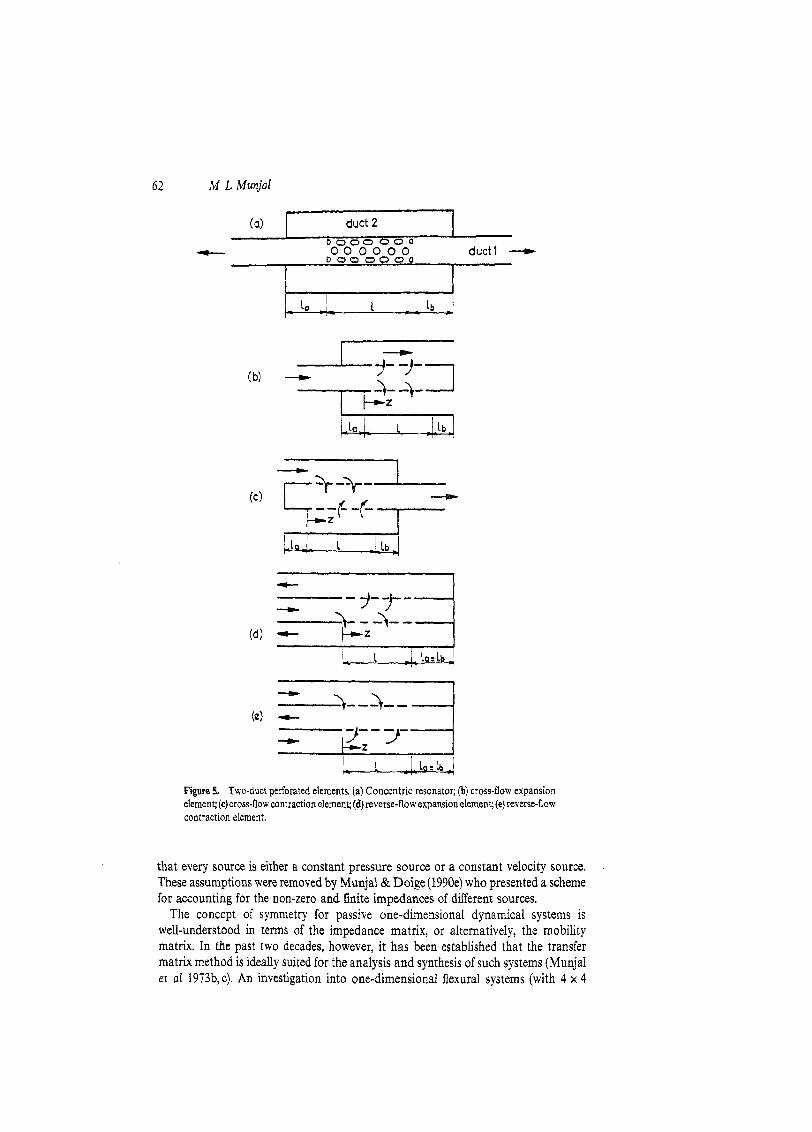
Perforate element mufflers (figures 5 and 6) are known to be much more efficient and versatile than the unperforated ones (figures 3 and 4). However, these elements could not be analysed until 1979, when Sullivan (1979) presented a segmentation procedure for modelling two-duct elements of figure 5, wherein the effect of
' (b) ----.I, 2 * .1 ----C
I Figure 3. Simple area discontinuities. (a) S d d e n contraction; (b) sudden expansion.
Advances in the acoustics of flow ducts and mufflers
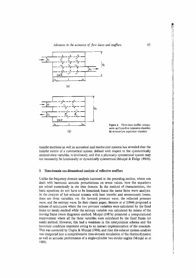
perforations was lumped at a number of discrete points connected by unperforated uniform tubes. However, Rao & Munjal (1984) developed a method of decoupling the otherwise coupled wave equations in the inner tube and the outer annular tube, and thus derived transfer matrices for the concentric tube resonator, the cross-flow expansion element and the cross-flow contraction element. This was later generalized as an eigenvalue problem (Munjal et al 1987) and closed-form expressions for the transfer matrix parameters were derived for the two-duct reverse-flow elements of figure 5 (Munjal et a1 15186) and the three-duct elements of figure 6 (Rao & Munjal 1986b).
Exhaust systems of IC engines are characterized by a mean temperature gradient along every cons:ir~mnt pipe. A theoretical study, involving solution of inhomogeneous wave equation by means of Green's functions, on the propagation of plane waves in the presence of a hot mean flow in a uniform pipe, yielded the fourpole parameters of such a pipe (Munjal 'Pt Prasad 1986).
A typical gas pipeline network consists of many pipes, T-joints, parallel paths, orifice plates, valves, etc. with several compressors as sources. Xie et a1 (1982) developed a comprehensive program to analyse such complex systems. However they had to make some unrealistic assumptions regarding the source impedance; they assumed
(d) C- - ' I - I
Figure 4. Extended tube resonators. (a) Extended outlet; (b) extended inlet;
I (c) reversal-expansion; (d) reversal- L Z 4 contraction.
62 M L Munjal
Figure 5. Two-duct perforated elements. (a) Concentric resonator; (b) cross-flow expansion element; (c)cross-flow contraction element; (d) reverse-flow expansion element; (e) reverse-flow contraction element.
that every source is either a constant pressure source or a constant velocity source. These assumptions were removed by Munjal& Doige (1990e) who presented a scheme for accounting for the non-zero and finite impedances of different sources.
The concept of symmetry for passive one-dimensional dynamical systems is well-understood in terms of the impedance matrix, or alternatively, the mobility matrix. In the past two decades, however, it has been established that the transfer matrix method is ideally suited for the analysis and synthesis of such systems (Munjal et al 1973b,c). An investigation into one-dimensional flexural systems (with 4 x 4
Advances in the acoustics of flow ducts and muflers
l a . . 1 Figure 6. Three-duct muffler compo- nents. (a) Cross-flow expansion chamber,
(b) (b) reverse-flow expansion chamber.
transfer matrices) as well as acoustical and mecharical systems has revealed that the transfer matrix of a symmetrical system; defined with respect to the symmetrically oriented state variables, is involutory, and that s! physically symmetrical system may not necessarily be functionally or dynamically symmetrical (Munjal & Doige 1990b).
3. Time-domain one-dimensional analysis of reflective mufflers
Unlike the frequency domain analysis discussed in the preceding section, where one deals with harmonic acoustic perturbations on mean values, here the equations are solved numericaiiy in the time domain. In the method of characteristics, the basic equations do not have to be linearized; hence the name finite wave analysis. In the analysis of hot exhaust systems with heat transfer and aeroacoustic losses, there are three variables; viz. the forward pressure wave, the reflected pressure wave, and the entropy wave. In their classic paper, Benson et a1 (1964) proposed a scheme of c a l c ~ r ~ t i o n where the two presure variables were calculated by the fixed frame (or mesh) method while the entropy variable was calculated by means of the moving frame (wave diagrams) method. Munjal (1987a) presented a computational improvement where a11 the three variables were calculated by the fixed frame (or mesh) method. However, this had a weakness in the interpolation scheme and the boundary condition treatment owing to an inexact implementation of the concepts. This was corrected by Gupta & Munjal(1988), and then the exhaust system analysis was integrated into a comprehensive time-domain simulation of the thermodynamic as well as acoustic performance of a single-cylinder two-stroke engine (Munjal et a1 1984').
64 M L Munjal
4. Aeroacoustic measurement
Measurements are required for supplementing the analysis by providing certain basic data or parameters that cannot be predicted precisely, for verifying the analytical or numerical predictions, and also for evaluating the overall performance of a system configuration in order to check if it satisfies the design requirements. The convective and dissipative effects of the moving medium affect the acoustic measurements in several ways as will be clear from the following paragraphs.
Among different methods, the transmission-line or the impedance tube method has been the most popular for the experimental evaluation of the acoustical impedance of any termination. The state of this method until 1974 involved extrapolation of the measured data to the reflecting surface or exact locations of the pressure maxima, both of which were known to be rather tricky. Kathuriya & Munjal(1975) developed a method which made use of the positions of the pressure minima and the values of the standing wave ratio at these points. In the process, the concept of enveloping curves (Lippert 1953) was extended. A little later, this scheme was extended to the case of a moving medium (Kathuriya & Munjal1976). For low frequency measurement by this method the length of the impedance tube would have to be rather large. Therefore, a new method was proposed where, unlike the usual method of locating at least two pressure minima, only three readings of sound pressure level and their corresponding locations were shown to be sufficient for evaluation of the impedance at low frequencies (Kathuriya & Munjal 1977a). This discrete measurement method was then extended to any frequency with o r without mean flow (Kathuriya & Munjal 1977b). Actual measurements indicated that this method, with its advantages of convenience, can indeed be used in practice provided (i) one relies primarily on the sound pressure level (SPL) measurements around a minimum of the standing wave, (ii) one does not make use of simultaneous evaluation of the amplitude and phase of the reflection coefficient, and (iii) one makes use of the expressions derived by Panicker & Munjal (1981~) for wave numbers and attenuation constants of two progressive waves (Panicker & Munjal 198 Id). This method was then used successfully to measure radiation impedance of an unflanged pipe with mean flow, and empirical relations were developed for the reflection coefficient (modulus as well as phase angle) and the radiation resistance and reactance (Panicker & Munjal 1982). The same method was made use of in an ingenious way to measure the impedance of perforates with grazing flow as required in the analysis of concentric tube resonators. These parametric measurements led to a fairly general empirical formula for the grazing-flow impedance of perforated plates (Rao & Munjal 1986a).
The aforesaid method is cumbersome as it involves discrete frequency measurements. Chung & Blaser (1980) developed a random-excitation, two-microphone, transfer- function method. The same has now been extended to incorporate the effects of moving medium and damping (Munjal & Doige 1990~).
Computer simulation of the acoustic behaviour of gas-pipeline systems, or other ducted systems using two-by-two transfer matrices requires theoretical models for all elements in the system. Occasionally, some elements may be encountered for which passive sound transmission characteristics have not yet been described adequately by theory. Examples include orifice plates or partially opened control values in pipelines with mean gas flow, or elements having strong three-dimensional wave behaviour. Many of these kinds of elements are noise sources as well as transmission elements. A new method has been developed for experimentally determining the matrix
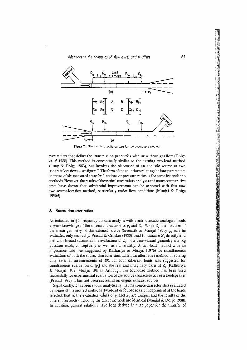
Advances in the acoustics of flow ducts and muflers
. . ---- (a) L z L
Figure 7. The two test configurations for the two-source method.
parameters that define the transmission properties with or without gas flow (Doige et a1 1988). This method is conceptually similar to the existing two-load method (Lung & Doige 19831, but involves the placement of an acoustic source at two separate locations - see figure 7. The form of the equations relating the four parameters in terms of six measured transfer functions or pressure ratios is the same for both the methods. However, the results of theoretical uncertainty analyses and many comparative tests have shown that substantial improvements can be expected with this new two-source-location method, particularly under flow conditions (Munjal & Doige 1990d).
5. Source characterization
As indicated in Q: 2, frequency-domain analysis with electroacoustic analogies needs a prior knowledge of the source characteristics p , and 2,. While Z, is a function of the mean geometry of the exhaust source (Sreenath & Munjal 1970), p , can be evaluated only indirectly. Prasad & Crocker (1983) tried to measure 2, directly and met with limited success as the evaluation of Z, for a time-variant geometry is a big question mark, conceptually as well as numerically. A two-load method with an impedance tube was suggested by Kathuriya & Munjal (1976) for simultaneous evaluation of both the source characteristics. Later, an alternative method, involving only external measurements of SPL for four different loads was suggested for simultaneous evaluation of lpsl and the real and imaginary parts of 2, (Kathuriya & Munjal 1979; Munjal 1987a). Although this four-load method has been used successfully for experimental evaluation of the source characteristics of a loudspeaker (Prasad 1987), it has not been successful on engine exhaust sources.
Significantly, it has been shown analytically that the source characteristics evaluated by means of the indirect methods (two-load or four-load) are independent of the loads selected; that is, the evaluated values of p, 2bd 2, are unique, and the results of the different methods (including the direct method) are identical (Munjal & Doige 1988). In addition, general relations have been derived in that paper for the transfer of
source characteristics from one station to another station across one or more acoustical elements and also for combining several sources into a single equivalent source.
It was indicated earlier in $ 2 that for waves in a moving medium, the acoustic variables p and u need to be replaced by the convective variables p, and v,, respectively. Thus one would need to relate the convective source characteristics p,,, and Z,, with their acoustic counterparts p, and 2,. These relations have been derived recently by Munjal & Doige (1990a).
The formal equivalence of the various methods for evaluation of the source characteristics, however, does not imply that they would yield exactly the same numerical values in a particular test situation. As shown by Doige & Alves (1986), one method may be more error-prone than another for a particular source. h fact, for the time-variant geometry of the engine exhaust source, even the uniqueness criterion is violated; i.e. the source chb;acteristics evaluated numerically, by means of a novel, linear time-domain scheme as well as the method of characteristics, seem to depend on rhe loads selected (Gupta & Munjal 1990). Thus, for an engine exhaust source, while the frequency-domain analysis may hold, the existence of invariant source characteristics is questionable!
6. Lined ducts and dissipative mufflers
Mufflers used in heating, ventilation and air-conditioning (HVAC) ducts, iridustrial fans, ventilation and access openings of acoustic enclosures, intake and exhaust ducts of power stations, cooling tower installations. gas turbines, and jet-engine test cells act not only by muffling the sources through successive reflections of sound by means of impedance mismatching but also by dissipating the incident sound energy as heat. These mufflers are, in fact, primarily dissipative mufflers with the advantage of providing definite attenuation of sound over a wide range of frequencies.
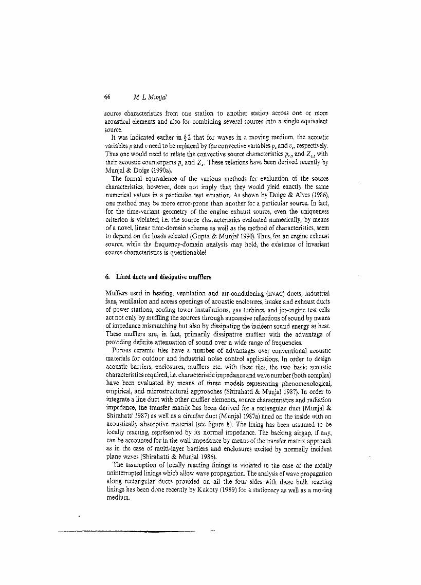
Porous ceramic tiles have a number of advantages over conventional acoustic materials for outdoor and industrial noise control applications. In order to design acoustic barriers, enclosures, mufflers etc. with these tiles, the two basic acoustic characteristics required, i.e. characteristic impedance and wave number (both complex) have been evaluated by means of three models representing phenomenological, empirical, and microstructural approaches (Shirahatti & Munjal 1987). In order to integrate a line duct with other mumer eIements, source characteristics and radiation impedance, the transfer matrix has been derived for a rectangular duct (Munjal & Shirahatti 1987) as well as a circular duct (Munjal 1987a) lined on the inside with an acoustically absorptive material (see figure 8). The lining has been assumed to be locally reacting, represented by its normal impedance. The backing airgap, if ally, can be accounted for in the wall impedance by means of the transfer matrix approach as in the case of multi-layer barriers and enclosures excited by normaily incident plane waves (Shirahatti & Munjal 1986).
The assumption of locally reacting linings is violated in the case of the axially uninterrupted Iinings which allow wave propagation. The analysis of wave propagation along rectangular ducts provided on all the four sides with these bulk reacting linings has been done recently by Kakoty (1989) for a stationa~y as well as a moving medium.
Advances in the acoustics of j7ow ducts and mufflers
Y
(a) (b)
Figure 8. Cross-section of acoustically liaed ducts. (a) Rectangular duct; (b) Circular duct.
7. Three-dimensional numerical analysis of mufflers
Three-dimensional effects are a primary source of discrepancies between the rneasured values of automotive mulrfler performance and those predicted by the plane-wave theory at higher frequencies. The author presented a simple collocation method, making use of compatibility conditions for acoustic pressure and particle velocity at a number of equally spaced points in the planes of the junctions (or area discontinuities) to generate the required number of aigebraic equations for evaluation of the relative amplitudes of the various modes (eigenfunctions), the total number of which is equal to the area ratio. The method is demonstrated for evaluation of the four-pole parameters of the rigid-walled, simple expansion chambers of rectangular as well as circular cross-section for the case of a stationary medium (Munjal1987b). 3-D analysis of mufflers with more complex shapes would, however, require use of the finite element method (FEM). Researchers in FEM have often restricted themselves to two-dimensional analysis with simplifying assumptions. Recently, the variational approach with Hermite polynomial shape functions and the Galerkin weighted residual approach with isoparanietric elements have been presented for a truly 3-D analysis of simple expansion chamber mumers (Sahasrabudhe et a1 1988). This requires hundreds of modes resulting in tedious data preparation and solution of a large number of simultaneous equations, which put a heavy strain on the core memory and computational efficiency of the computer. This can be reduced by means of the recursive substructuring principle for the repetitive segments of the expansion chamber muffler. The muffler is divided into substructures and each substructure is partitioned into 2"(m is an integer) repetitive segments, which are then solved locally by applying a matrix condensation technique (Sahasrabudhe el a1 1989). Making use of this and the transfer matrix method, a finite element computer program has been developed for the 3-D analysis of the extended-tube expansion chamber as well as simple expansion chamber mufflers.
It is weil-known that a sudden area discontinuity (figures 3 and 4) generates higher order, evanescent acoustic waves even at low frequencies within the plane-wave limit. This is attributable to the inertance effect, which has been evaluated through FEM as a function of the radius ratio, frequency and the offset distance (Sahasrabudhe 1989).
68 ICI L Munjal
8. Active noise control
Both reflective as well as d l s s i l 37
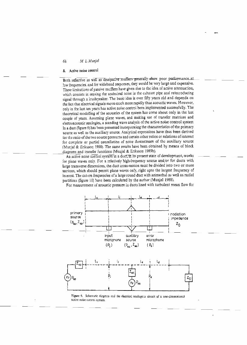
low frequencies, and for wideband responses, they would be very large and expensive. These limitations of passive mufilers have given rise to the idea of active attenuation, which consists in sensing the undesired noise in the exhaust pipe and reintroducing signal through a loudspeaker. The basic idea is over fifty years old and depends on the fact that electrical signals move much more rapidly than acoustic waves. However, only in the last ten years has active noise control been implemented successfully. The theoretical modelling of the acoustics of the system has come about only in the last couple of years. Assumjng plane waves, and making use of transfer matrices and electroacoustic analogies, a standing wave analysis of the active noise control system in a duct (figure 9) has been presented incorpora~ing the characteristics of the primary source as well as the auxiliary source. Analytical expressions have thus been derived for the ratio of the two source pressures and certain other ratios or relations of interest for complete or partial cancellation of noise downstream of the auxiliary source (Munjal & Eriksson 1988). The same results have been obtained by means of block diagrams and transfcr functions (Munjal & Eriksson 1989b).
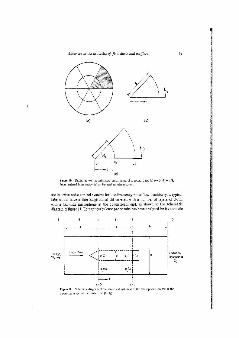
An active noise control-, in irs-ks for plane waves only. For a relatively high-frequency source and/or for ducts with large transverse dimensions, the duct cross-section must be divided into two or more sections, which should permit plane waves only, right upto the largest frequency of interest. The cut-on frequencies of a large round duct with azimuthal as well as radial partitions (figure 10) have been calculated by the author (Munjal 1988).
For measurement of acoustic pressure in ducts lined with turbulent mean flow for
I I I
I I I I 1
primary I I I I I I I I radiation
source I I
I I I I I impedance
(psp,Zsp) I I I I I I I zo I
in iu t I
auxiliary error microphone source microphone (Pi 1 p s 1 ( PC)
Figure 9. Schematic dizgram and the electrical analogous circuit of a one-dimecsional actise noise control system.
Advances in the acoustics of flow ducts and mufflers
I--r (c)
Figure 10. Radial as well as azimuthal partitioning of a round duct: (a) q = 3, 0, = n/3; (h) an isolated inner sector; (c) an isolated annular segment.
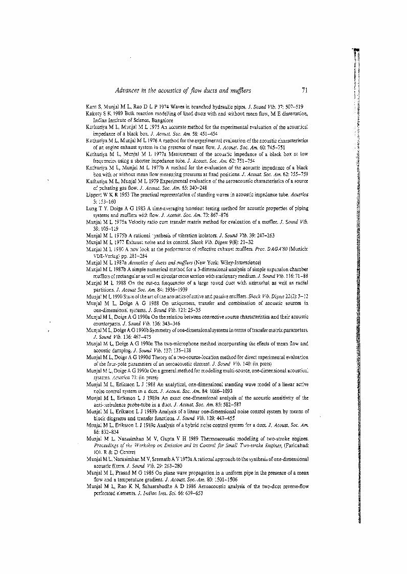
use in active noise control systems for low-frequency noise flow machinery, a typical tube would have a thin longitudinal slit covered with a number of layers of cloth, with a half-inch microphone at the downstream end, as shown in the schematic diagram of figure 11. This antiturbulence probe tube has been analysed for its acoustic
I radiation I impedance
I 20 1
Figure 11. Schematic diagram of the acoustical system with the microphone located at the downstream end of the probe tube (I = I,).

70 M L Munjal
sensitivity or frequency response by means of the distributed parameter approach wherein mutual interaction of the acoustic pressure fields in the probe tube and the annular duct is considered (Munjal & Eriksson 1988a). In a typical one-dimensional active noise control system (figure 9): the auxiliary
source (generally a loudspeaker) must produce an acoustic pressure equal (and opposite in phase) to that produced by the primary source at the loudspeaker junction. If the ratings of the power amplifier and the loudspeaker are not adequate, there will be little reduction of noise at the radiation end. One way out is to replace the duct length 1, by a passive muMer (reflective or dissipative) upstream of the input microphone. Such a hybrid system has been analysed by making use of electroacoustic analogies and the transfer matrix method (Munjal & Eriksson 1989~).
9. Challenges ahead
Over the last two decades, there have been considerable advances (Munjal 1987a, 1990). However, considerable research inputs are still needed in
(a) time-domain analysis of the extended-tube chamber and the perforated-element mufflers,
(b) FEM analysis of complex geometries like perforated-element mufflers, (c) analysis of lined ducts with splitters (protective perforated plate), (d) development of the boundary element methods for 3-D analysis of mufflers, (e) aeroacoustic modelling of orifice plates and control valves, (f) frequency-domain characterization of the engine exhaust source, (g) development of the cost-effective active noise control systems for the HVAC and
engine exhaust systems, and (h) prediction of shell noise for typical commercial mufflers.
Work on some of these problems is going on in this Institute as also elsewhere in the world.
References
Alfredson R J, Davies P 0 A L 1970 The radiation of sound from an engine exhaust. J . Sound Vib. 13: 389-408
Alfredson R J, Davies P 0 A L 1971 Performance of exhaust silencer components. J . Sound Vib. 15: 175-196 Benson R S, Garg R D, Woollatt D 1964 A numerical solution of unsteady flow problems. Int. J . Mech.
Sci. 6: 117-144 Chung J Y, Blaser D A 1980a Transfer function method of measuring in-duct acoustic properties I: Theory.
J . Acoust. Soc. Am. 68: 907-913 Chung J Y, Blaser D A 1980b Transfer function method of measuring in-duct acoustic properties.
11: Experiment. J. Acoust. Soc. Am. 68: 914-921 Doige A G, Alves H S 1986 Experimental characterization of noise sources for duct acoustics, ASME
36-WA/NCA-15, Anaheim, California Doige A G, Munjal M L, Alves H S 1988 An improved experimental method for determining transfer
matrices of pipeline elements with flow. Proc. NOISE-CON 88 (New York: Inst. Noise Control Eng.) pp. 481-486
Gupta V H, Munjal M L 1988 A time-domain simulation of an IC engine exhaust system. J. Acoust. Soc. India 14: 299-305
Gupta V H, Munjal M L 1990 On numerical prediction of source characteristics of a single cylinder reciprocating engine, Report No. SV/IISc/!/61/391-Rl, Indian Institute of Science, Bangalore
Advances in the acoustics of flow ducts and muflers 7 1
Kant S, Munjal M L, Rao D L P 1974 Waves in branched hydraulic pipes. J . Sound Vib. 37: 507-519 Kakoty S K 1989 Bulk reaction modelling of lined ducts with and without mean flow, M E dissertation,
Indian Institute of Science, Bangalore Kathuriya M L, Munjal M L 1975 An accurate method for the experimental evaluation of the acoustical
impedance of a black box. 3. Acoust. Soc. Am. 58: 451-454 Kathuriya M L, Munjal M L 1976 A method for the experimental evaluation of the acoustic characteristics
of an engine exhaust system in the presence of mean flow. J. Acoust. Soc. Am. 60: 745-751 Kathuriya M L, Munjal M L 19773. Measurement of the acoustic impedance of a black box at low
frequencies using a shorter impedance tube. 3. Acoust. Soc. Am. 62: 751-754 Kathuriya M L, Munjal M L 1977b A method for the evaluation of the acoustic impedance of a black
box with or without mean flow measuring pressures at fixed positions. J. Acoust. Sac. Am. 62: 755-759 Kathuriya M L, Munjal M L 1979 Experimental evaluation of the aeroacoustic characteristics of a source
of pulsating gas flow. J. Acoust. Soc. Am. 65: 240-248 Lippert W K R 1953 The practical representation of standing waves in acoustic impedance tube. Acustica
3: 153-160 Lung T Y, Doige A G 1983 A time-averaging transient testing method for acoustic properties of piping
systems and mufflers with now. J. Acoust. Soc. Am. 73: 867-876 Munjal M L 1975a Velocity ratio cum transfer matrix method for evaluation of a mufller. 3. Sound Vib.
39: 105-119 Munjal M L 1975b A rational *ynthesis of vibration isolators. J. Sound Yib. 39: 247-263 Munjal M L 1977 Exhaust noise and its control. Shock Vib. Digest 9(8): 21-32 Munjal M L 1980 A new look at the performance of reflective exhaust mufflers. Proc. DAGA'80 (Munich:
VDE-Verlag) pp. 281-284 Munjal M L 1987a Acoustics of ducts and muflers (New York: Wiley-Interscience) Munjal M L 1987b A simple numerical method for a 3-dimensional analysis of simple expansion chamber
mufflers of rectangular as well as circular cross section with stationary medium. J . Sound Vib. 116: 71-88 Munjal M L 1988 O n the cut-on frequencies of a large round duct with azimuthal as well as radial
partitions. J. Acoust Soc. Am. 84: 1936-i939 Munjal M L 1910 State of the art of the acoustics ofactive and passive mufflers. Shock Vib. Digest 22(2): 3-12 Munjal M L, Doige A G 1988 On uniqueness, transfer and combination of acoustic sources in
one-dimensional systems. J . Sound Vib. 121: 25-35 Munjal M L, Doige A G 1990a On the relation between convective source characteristics and their acoustic
counterparts. J. Sound Yib. 136: 343-346 Munjal M L, Doige A G 1990b Symmetry of one-dimensional systems in terms of transfer matrix parameters.
J . Sound Vib. 136: 467-475 Munjal M L, Doige A G 1990c The two-microphone method incorporating the effects of mean Bow and
acoustic damping. J . Sound Vib. 137: 135-138 Munjal M L, Doige A G 1990d Theory of a two-source-location method for direct experimental evaluation
of the four-pole parameters of an aeroacoustic element. J. Sound Vib. 140: (in press) Munjal M L, Doige A G 1990e On a general method for modelling multi-source, one-dimensional acoustical
systems. Acustica 71: (in press) Munjal M L, Eriksson L J 1988 An analytical, one-dimensional standing wave model of a linear active
noise control system in a duct. 3. Acoust. Soc. Am. 84: 1086-1093 Munjal M L, Eriksson L J 1989a An exact one-dimensional analysis of the acoustic sensitivity of the
anti-turbulence probe-tube in a duct. 3. Acoust. Soc. Am. 85: 582-587 Munjal M L, Eriksson L J 1989b Analysis of a linear one-dimensional noise control system by means of
block diagrams and tra.nsfer functions. J . Sound Vib. 129: 443-455 Munjal M L, Eriksson L J 1989c Analysis of a hybrid noise control system for a duct. J . Acousr. Soc. Am.
86: 832-834 Munjal M L, Narasimhan M V, Gupta V H 1989 Thermoacoustic modelling of two-stroke engines.
Proceedings of the Workshop on Emission and its Control for Small Two-stroke Engines, (Faridabad: 10L R & D Centre)
Munjal M L,Narasimhan M V, Sreenath A V 1973a A rational approach to the synthesis of one-dimensional acoustic filters. J. Sound Vib. 29: 263-280
Munjal M L, Prasad M G 1986 On plane wave propagation in a uniform pipe in the presence of a mean flow and a temperature gradient. J . Acoust. Spc..Am. 80: 1501-1506
Munjal M L, Rao K N, Sahasrabudhe A D 1986 Aeroacoustic analysis of the two-duct reverse-flow perforated elements. J . Indian Inst. Sci. 66: 639-653
M L Munjal
Munjal M L, Rao K N, Sahasrabudhe A D 1987 Aeroacoustic analysis of perforated muffler components. J. sourad Vib. 114: 173-188
Munjal M L, Shirahatti U S 1987 Analysis of lined ducts with mean flow, with application to dissipative mufflers. Trans. ASME ( J . Vib. Acoust. Stress Reliability) 109: 366-371
Munjal M L, Sreenath A V, Narasimhan M V 1973b Velocity ratio in analysis of linear dynamical systems. J. Sound Vib. 26: 173-191
Munjal M L; Sreenath A V. Narasimhan M V 1 9 7 3 ~ An algebraic algorithm for the design and analysis of linear dynamical systems. J. Sound Vib. 26: 193-208
Olson H F 1966 Dynarnicai analogies 3rd edn. (Princeton, NJ: Van Nostrand) Panicker V B, Munjal M L 1981a Aeroacoustic analysis of straight-through mumers with simple and
extended-tube expansion chambers. J. Indian Inst. Sci. A63: 1-19 Panicker V B, Munjal M L 1981bAeroacoustics ofmufilers with flow reversals. J . Indian Inst. Sci. A63: 21-38 Panicker V B, Munjal M L 1981c Acoustic dissipation in a uniform tube with moving medium. 3. Acoust.
Soc. India 91: 95-101 Panicker V B, Munjal M L 1981d Impedance tube technology for flow acoustics. J . Sound Vib. 77: 573-577 Panicker V B, Munjal M L 1982 Radiation impedance of an unflanged pipe with mean flow. Noise Control
Eng. 18: 48-51 Prasad M G 1987 A four-load method for evaluation of acoustical source impedance in a duct. J. Sound
Vib. 114: 347-356 Prasad M G, Crocker M J 1983 On the measurement of the internal source impedance of a multi-cylinder
engine exhaust system. J . Sound Vib. 90: 479-490 Rao K N, Munjal M L 1984 .A generalized decoupling method for analyzing perforated element mufflers,
Proc. Melson Acoustics Conf., Madison, USA Rao K N, Munjal M L 1986a Experimental evaluation of impedance of perforates with grazing flow. J .
Sound Vib. 108: 283-295 Rao K N, Munjal M L 1986b Noise reduction with perforated three-duct muffler components. Sadhand
9: 255-269 Sahasrabudhe A D 1989 An eflcient three-dimensional finite element analysis of simple and extended-tube
expansion chamber mufflers, PhD thesis, Indian Institute of Science, Bangalore Sahasrabudhe A D, Munjal M L, Ananthi ,amu S 1988 Finite element analysis of simple expansion chamber
mumers. J. Acoust. Soc. India 16: 293-298 Sahasrabudhe A D: Munjal M L, Anantharamu S 1989 Finite element analysis of expansion chamber
muRlers by recursive substructuring of repetitive segments. Twelfth Biennial ASME Conference on Mechanical Vibration and Noise (Montreal: ASME)
Shirahatti U S, Munjal M L 1986 Acoustic performance of composite-walled barriers and enclosures with ceramic sound-absorber tiles. J . Acoust. Soc. India 14: 193-198
Shirahatti U S, Munjal M L 1987 Acoustical characterization of porous ceramic tiles. Noise Control Eng. J . 28: 26-32
Sreenath A V, Munjal M L 1970 Evaluation of noise attenuation due to exhaust mufflers. J. Sound Vib. 12: 1-19
Sullivan J W 1979a A method of modeling perforated tube muffler components. I: Theory. 3. Acoust. Soc. Am. 66: 772-778
Sullivan J W 1979b A method of modeling perforated tube mufller components. 11: Applications. 3. Acoust. Soc. Am. 66: 779-788
Xie Z, Doige A G, Lung T Y 1982 Modelling pressure pulsation in piping systems with an arbirary number of inputs and outputs. Proc. ASME-PVP Spring Mtg. (Montreal: ASME)