Advances in Mechanical Engineering On a Jansen leg … · Reconfigurable linkages, legged...
18
Special Issue Article Advances in Mechanical Engineering 1–18 Ó The Author(s) 2015 DOI: 10.1177/1687814015573824 aime.sagepub.com On a Jansen leg with multiple gait patterns for reconfigurable walking platforms Shunsuke Nansai 1 , Nicolas Rojas 2 , Mohan Rajesh Elara 3 , Ricardo Sosa 3 and Masami Iwase 1 Abstract Legged robots are able to move across irregular terrains and those based on 1-degree-of-freedom planar linkages can be energy efficient, but are often constrained by a limited range of gaits which can limit their locomotion capabilities consid- erably. This article reports the design of a novel reconfigurable Theo Jansen linkage that produces awide variety of gait cycles, opening new possibilities for innovative applications. The suggested mechanism switches from a pin-jointed Gru ¨bler kinematic chain to a 5-degree-of-freedom mechanism with slider joints during the reconfiguration process. It is shown that such reconfigurable linkage significantly extend the capabilities of the original design, while maintaining its mechanical simplicity during normal operation, to not only produce different useful gait patterns but also to realize beha- viors beyond locomotion. Experiments with an implemented prototype are presented, and their results validate the pro- posed approach. Keywords Reconfigurable linkages, legged locomotion, planar mechanisms, Jansen linkage, walking platforms Date received: 8 December 2014; accepted: 19 January 2015 Academic Editor: Yan Jin Introduction Legged platforms are one of the most versatile design strategies for robot locomotion. The choice of leg-like mechanisms often responds to design requirements such as the ability to move through irregular terrains or to increase the stability and maneuverability in such envir- onments. 1 One of the main challenges of using legged robots in practical applications is how to control and adapt their gait—that is, finding a suitable and adapta- ble foot displacement trajectory. 2,3 Legged animals coordinate a wide range of components and systems to walk adaptively and efficiently under a variety of speeds, terrains, and task goals including chasing, courtship, and stealth. However, in nature, individuals are limited by their species morphology and are only able to change their gait from a limited number of alternatives. This article reports a reconfigurable approach to robotic legged locomotion that produces a wide variety of gait curves, opening new possibilities for innovative applications. The main departure from the state of the art in this area is that large solution spaces are generated using a 1-degree-of-freedom pla- nar linkage, producing gait variance via parametric 1 Tokyo Denki University, Tokyo, Japan 2 SUTD-MIT International Design Centre, Singapore; presently with the Department of Mechanical Engineering and Materials Science, Yale University, New Haven, CT, USA 3 Singapore University of Technology and Design, Singapore Corresponding author: Nicolas Rojas, Department of Mechanical Engineering and Materials Science, Yale University, New Haven, CT 06511, USA. Email: [email protected] Creative Commons CC-BY: This article is distributed under the terms of the Creative Commons Attribution 3.0 License (http://www.creativecommons.org/licenses/by/3.0/) which permits any use, reproduction and distribution of the work without further permission provided the original work is attributed as specified on the SAGE and Open Access pages (http://www.uk.sagepub.com/aboutus/ openaccess.htm).
Transcript of Advances in Mechanical Engineering On a Jansen leg … · Reconfigurable linkages, legged...

Special Issue Article
Advances in Mechanical Engineering1–18� The Author(s) 2015DOI: 10.1177/1687814015573824aime.sagepub.com
On a Jansen leg with multiple gaitpatterns for reconfigurable walkingplatforms
Shunsuke Nansai1, Nicolas Rojas2, Mohan Rajesh Elara3, Ricardo Sosa3 andMasami Iwase1
AbstractLegged robots are able to move across irregular terrains and those based on 1-degree-of-freedom planar linkages can beenergy efficient, but are often constrained by a limited range of gaits which can limit their locomotion capabilities consid-erably. This article reports the design of a novel reconfigurable Theo Jansen linkage that produces a wide variety of gaitcycles, opening new possibilities for innovative applications. The suggested mechanism switches from a pin-jointedGrubler kinematic chain to a 5-degree-of-freedom mechanism with slider joints during the reconfiguration process. It isshown that such reconfigurable linkage significantly extend the capabilities of the original design, while maintaining itsmechanical simplicity during normal operation, to not only produce different useful gait patterns but also to realize beha-viors beyond locomotion. Experiments with an implemented prototype are presented, and their results validate the pro-posed approach.
KeywordsReconfigurable linkages, legged locomotion, planar mechanisms, Jansen linkage, walking platforms
Date received: 8 December 2014; accepted: 19 January 2015
Academic Editor: Yan Jin
Introduction
Legged platforms are one of the most versatile designstrategies for robot locomotion. The choice of leg-likemechanisms often responds to design requirements suchas the ability to move through irregular terrains or toincrease the stability and maneuverability in such envir-onments.1 One of the main challenges of using leggedrobots in practical applications is how to control andadapt their gait—that is, finding a suitable and adapta-ble foot displacement trajectory.2,3 Legged animalscoordinate a wide range of components and systems towalk adaptively and efficiently under a variety ofspeeds, terrains, and task goals including chasing,courtship, and stealth. However, in nature, individualsare limited by their species morphology and are onlyable to change their gait from a limited number of
alternatives. This article reports a reconfigurableapproach to robotic legged locomotion that produces awide variety of gait curves, opening new possibilitiesfor innovative applications. The main departure fromthe state of the art in this area is that large solutionspaces are generated using a 1-degree-of-freedom pla-nar linkage, producing gait variance via parametric
1Tokyo Denki University, Tokyo, Japan2SUTD-MIT International Design Centre, Singapore; presently with the
Department of Mechanical Engineering and Materials Science, Yale
University, New Haven, CT, USA3Singapore University of Technology and Design, Singapore
Corresponding author:
Nicolas Rojas, Department of Mechanical Engineering and Materials
Science, Yale University, New Haven, CT 06511, USA.
Email: [email protected]
Creative Commons CC-BY: This article is distributed under the terms of the Creative Commons Attribution 3.0 License
(http://www.creativecommons.org/licenses/by/3.0/) which permits any use, reproduction and distribution of the work without
further permission provided the original work is attributed as specified on the SAGE and Open Access pages (http://www.uk.sagepub.com/aboutus/
openaccess.htm).

changes of link lengths. Our ultimate aim is to buildrobots that can entirely redesign their morphologiesaccording to changes in the environment and to reflecttheir learning of new abilities. This article represents aninitial step toward robots that self-design themselves.We envision robots equipped with reconfigurable legsto generate a large number of locomotion capabilitiesduring their deployment. Alternatively, for tasks thatrequire single-purpose mechanisms, our approach canbe used as a design approach to explore and select opti-mal yet feasible configurations that can be used to buildspecialized walking robots.
The literature shows a variety of design strategies togenerate gait patterns, including adaptive locomotioncontrol,4 use of hybrid locomotive mechanisms,5 struc-tural combination of rigid and tensile structural ele-ments,6 joint torque and position control of compliantlegs,7 morphological computation,8 oscillator controllerwith pneumatic actuators,2 and biomimetic adaptationsbased on ground contact timing9 or using sensorimotorcoordination.10 A reconfigurable design approach ispresented in this article where a robot can vary its hard-ware morphology by parametric changes of its compo-nents. In particular, a novel reconfigurable Theo Jansenlinkage that produces a wide variety of gait cycles isreported (Figure 1). The standard Theo Jansen linkage
is a popular closed kinematic chain suitable for devel-oping legged robots, such pin-jointed planar linkageoperates with only one actuator—that is, it is a Grublerkinematic chain. The proposed design extends the cap-abilities of the original mechanism, while maintainingits mechanical simplicity during normal operation, gen-erating different useful gait patterns and behaviorsbeyond locomotion.
The main challenges in designing a reconfigurableversion of a Theo Jansen linkage include the develop-ment of efficient approaches to trace foot trajectories—that is, coupler curves, the definition of the novelty andutility of the resulting foot trajectories, the develop-ment of heuristics to guide the reconfiguration process,and the non-trivial process of implementing theoreticaldesigns generated analytically into physical mechan-isms. All these aspects are handled in this article, con-cluding with experimental results using a prototypefabricated with a minimum amount of off-the-shelfparts. The reconfigurable Theo Jansen linkage hereinpresented is an initial design and implementation of afour-legged robot for testing different reconfigurationscenarios and control strategies for limb specializationand graceful degradation.
The rest of this article is organized as follows.Section ‘‘Reconfigurable linkages and design’’ presentsa discussion about reconfigurable linkages, the pro-posed mechanism design approach, and the mainlinkages used in walking machines. Section ‘‘Positionanalysis of a Theo Jansen linkage’’ introduces thedistance-based formulation for planar kinematic chainsand applies the bilateration method to address the posi-tion analysis problem of a Theo Jansen linkage. Section‘‘Beyond the standard Theo Jansen linkage: new gaitpatterns’’ identifies a sample set of gaits produced by areconfigurable design of this mechanism. Section‘‘Characterization of leg transformation’’ presents aprocedure for transforming a reconfigurable TheoJansen linkage between two given configurations thatproduce different gait patterns with clear potential forfuture applications. Sections ‘‘Implementation of areconfigurable Jansen leg’’ and ‘‘Performance’’ showthe design of a reconfigurable Theo Jansen linkage andthe result of experiments with a prototype, respectively.Finally, Section ‘‘Conclusion’’ concludes this study anddiscusses future work.
Reconfigurable linkages and design
A linkage can be modeled in general as a system of geo-metrical constraints, that is, a group of geometricalelements—for example, points, lines, circles, andpolygons—subject to geometrical measures—for exam-ple, angles, lengths, areas, and volumes—and geometri-cal relations—for example, ratios, congruences,
Figure 1. Prototype of a reconfigurable Jansen leg that extendsthe capabilities of the original design, while maintaining itsmechanical simplicity during normal operation. This linkage,which switches from a pin-jointed Grubler kinematic chain to a5-degree-of-freedom mechanism with slider joints in thereconfiguration process, not only produces different useful gaitpatterns but also generates behaviors beyond locomotion.
2 Advances in Mechanical Engineering
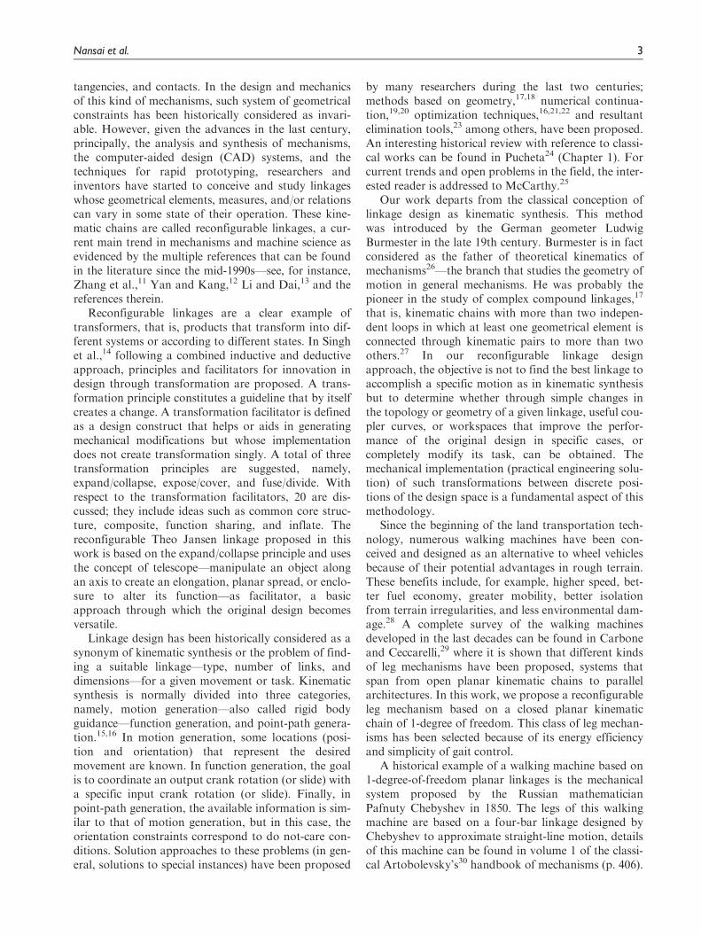
tangencies, and contacts. In the design and mechanicsof this kind of mechanisms, such system of geometricalconstraints has been historically considered as invari-able. However, given the advances in the last century,principally, the analysis and synthesis of mechanisms,the computer-aided design (CAD) systems, and thetechniques for rapid prototyping, researchers andinventors have started to conceive and study linkageswhose geometrical elements, measures, and/or relationscan vary in some state of their operation. These kine-matic chains are called reconfigurable linkages, a cur-rent main trend in mechanisms and machine science asevidenced by the multiple references that can be foundin the literature since the mid-1990s—see, for instance,Zhang et al.,11 Yan and Kang,12 Li and Dai,13 and thereferences therein.
Reconfigurable linkages are a clear example oftransformers, that is, products that transform into dif-ferent systems or according to different states. In Singhet al.,14 following a combined inductive and deductiveapproach, principles and facilitators for innovation indesign through transformation are proposed. A trans-formation principle constitutes a guideline that by itselfcreates a change. A transformation facilitator is definedas a design construct that helps or aids in generatingmechanical modifications but whose implementationdoes not create transformation singly. A total of threetransformation principles are suggested, namely,expand/collapse, expose/cover, and fuse/divide. Withrespect to the transformation facilitators, 20 are dis-cussed; they include ideas such as common core struc-ture, composite, function sharing, and inflate. Thereconfigurable Theo Jansen linkage proposed in thiswork is based on the expand/collapse principle and usesthe concept of telescope—manipulate an object alongan axis to create an elongation, planar spread, or enclo-sure to alter its function—as facilitator, a basicapproach through which the original design becomesversatile.
Linkage design has been historically considered as asynonym of kinematic synthesis or the problem of find-ing a suitable linkage—type, number of links, anddimensions—for a given movement or task. Kinematicsynthesis is normally divided into three categories,namely, motion generation—also called rigid bodyguidance—function generation, and point-path genera-tion.15,16 In motion generation, some locations (posi-tion and orientation) that represent the desiredmovement are known. In function generation, the goalis to coordinate an output crank rotation (or slide) witha specific input crank rotation (or slide). Finally, inpoint-path generation, the available information is sim-ilar to that of motion generation, but in this case, theorientation constraints correspond to do not-care con-ditions. Solution approaches to these problems (in gen-eral, solutions to special instances) have been proposed
by many researchers during the last two centuries;methods based on geometry,17,18 numerical continua-tion,19,20 optimization techniques,16,21,22 and resultantelimination tools,23 among others, have been proposed.An interesting historical review with reference to classi-cal works can be found in Pucheta24 (Chapter 1). Forcurrent trends and open problems in the field, the inter-ested reader is addressed to McCarthy.25
Our work departs from the classical conception oflinkage design as kinematic synthesis. This methodwas introduced by the German geometer LudwigBurmester in the late 19th century. Burmester is in factconsidered as the father of theoretical kinematics ofmechanisms26—the branch that studies the geometry ofmotion in general mechanisms. He was probably thepioneer in the study of complex compound linkages,17
that is, kinematic chains with more than two indepen-dent loops in which at least one geometrical element isconnected through kinematic pairs to more than twoothers.27 In our reconfigurable linkage designapproach, the objective is not to find the best linkage toaccomplish a specific motion as in kinematic synthesisbut to determine whether through simple changes inthe topology or geometry of a given linkage, useful cou-pler curves, or workspaces that improve the perfor-mance of the original design in specific cases, orcompletely modify its task, can be obtained. Themechanical implementation (practical engineering solu-tion) of such transformations between discrete posi-tions of the design space is a fundamental aspect of thismethodology.
Since the beginning of the land transportation tech-nology, numerous walking machines have been con-ceived and designed as an alternative to wheel vehiclesbecause of their potential advantages in rough terrain.These benefits include, for example, higher speed, bet-ter fuel economy, greater mobility, better isolationfrom terrain irregularities, and less environmental dam-age.28 A complete survey of the walking machinesdeveloped in the last decades can be found in Carboneand Ceccarelli,29 where it is shown that different kindsof leg mechanisms have been proposed, systems thatspan from open planar kinematic chains to parallelarchitectures. In this work, we propose a reconfigurableleg mechanism based on a closed planar kinematicchain of 1-degree of freedom. This class of leg mechan-isms has been selected because of its energy efficiencyand simplicity of gait control.
A historical example of a walking machine based on1-degree-of-freedom planar linkages is the mechanicalsystem proposed by the Russian mathematicianPafnuty Chebyshev in 1850. The legs of this walkingmachine are based on a four-bar linkage designed byChebyshev to approximate straight-line motion, detailsof this machine can be found in volume 1 of the classi-cal Artobolevsky’s30 handbook of mechanisms (p. 406).
Nansai et al. 3

In more recent times, two 1-degree-of-freedom leg lin-kages, both invented in the last 25 years, have stoodout, namely, the Klann mechanism and the Jansen link-age. The Klann mechanism, conceived by theMechanical Engineer Joe Klann31 in 1994, is aStephenson type III kinematic chain (a six-bar linkage)designed from the four-bar Burmester linkage devel-oped in 1888 for harbor cranes. The Jansen linkage cor-responds to an eight-bar kinematic chain; it wascreated by Theo Jansen32 during his works of fusion ofart and engineering, and the history of the linkagedevelopment and invention is described in his study.More details about this linkage are discussed laterherein. For the development of our reconfigurable leglinkage, we opted for the Theo Jansen’s solutionbecause of its higher potential of versatility, given thefact that the resulting coupler curve at the foot point isof higher degree than that of both the four-barChebyshev linkage and the six-bar Klann mechanism.An example of such versatility can be seen in the studyof Komoda and Wagatsuma,33 in which an extensionof the Theo Jansen linkage for climbing over bumps isproposed. This is perhaps the closer work to ourapproach.
Position analysis of a Theo Jansen linkage
The Theo Jansen linkage (‘‘Jansen leg’’ is the term usedin this article) is an eight-link 1-degree-of-freedom pla-nar linkage, that is, a Grubler kinematic chain, designedby the Dutch kinetic sculptor Theo Jansen32 during the1990s for emulating a smooth and elegant walkingmotion. This linkage, depicted in Figure 2, has threeindependent loops and consists of six binary links, oneternary link, and a coupler link with seven revolutejoints. Since one of the revolute joints involves threebinary links, the topology of this kinematic chain doesnot correspond to any of the 16 topologies of standard1-degree-of-freedom eight-bar linkages (see AppendixD in Tsai34).
In a Jansen leg, according to the notation ofFigure 2, the centers of the revolute joints of the binarylinks define the line segments P1P2, P1P6, P2P3, P3P4,P3P6, and P5P7; those for the ternary link define the tri-angle DP1P4P5; and those for the coupler link withpoint P8, the foot of a Jansen leg, define the triangleDP6P7P8. The position analysis problem for this link-age corresponds to, given the dimensions of every link,the position of the revolute joint centers P1 and P2, andan angle u for the input link, calculating all the feasibleCartesian locations of point P8. To this end, instead ofusing joint angles through independent loop-closureequations,35 we will use squared distances and bilatera-tion matrices to compute the corresponding valuesof P8.
The bilateration matrix
The bilateration problem consists in finding the feasiblelocations of a point, say Pk, given its distances to twoother points, say Pi and Pj, whose locations are known.Then, according to Figure 3, the solution to this prob-lem, in matrix form, can be expressed as
pi, k =Zi, j, k pi, j ð1Þ
where pi, j =PiPj��!
and
Zi, j, k =1
2 si, j
si, j + si, k � sj, k �4 Ai, j, k
4 Ai, j, k si, j + si, k � sj, k
� �
is called a bilateration matrix, with si, j = d2i, j = jjpi, jjj
2,the squared distance between Pi and Pj, and
Ai, j, k = 61
4
ffiffiffiffiffiffiffiffiffiffiffiffiffiffiffiffiffiffiffiffiffiffiffiffiffiffiffiffiffiffiffiffiffiffiffiffiffiffiffiffiffiffiffiffiffiffiffiffiffiffiffiffiffiffiffiffiffiffiffiffiffiffiffiffiffiffiffiffiffiffiffiffiffiffiffiffiffiffiffiffiffiffisi, j + si, k + sj, k
� �2 � 2 s2i, j + s2
i, k + s2j, k
� rð2Þ
the oriented area of DPiPjPk which is defined as posi-tive if Pk is to the left of vector pi,j and negative other-wise. It can be observed that the product of twobilateration matrices is commutative. Then, it is easy to
Figure 2. The Jansen leg, a 1-degree-of-freedom planar linkageof eight links, seven revolute joints, one of them involving threebinary links, and three independent loops.
4 Advances in Mechanical Engineering

prove that the set of bilateration matrices, that is,
matrices of the forma �b
b a
�, constitute a commuta-
tive group under the product and addition operations.Moreover, if v = Zw, where Z is a bilateration matrix,
then jjvjj2 = det (Z)jjwjj2. The interested reader isaddressed to Rojas26 for a derivation of equation (1)and its properties.
It has been shown that by using bilaterationmatrices, the position analysis problem of linkages isgreatly simplified—see, for instance, Rojas andThomas.36,37 This problem consists of finding the feasi-ble assembly modes that a kinematic chain can adopt.An assembly mode is a possible relative transformationbetween the links of a kinematic chain or linkage.When an assignment of positions and orientations ismade for all links with respect to a given referenceframe, an assembly mode is called a configuration.Next, we present how to apply the bilateration methodfor solving the position analysis problem of aJansen leg.
Bilateration-based system of equations
First, according to the notation of Figure 2, let us com-pute p1,3 from u and the location of the revolute jointcenters P1 and P2. That is
p1, 3 =Z1, 2, 3 p1, 2 ð3Þ
with s1,3 = s1,2 + s2,3 2 2d1,2d2,3 cos u. Now, follow-ing a simple geometric constructive process from p1,3,we get
p1, 4 =Z1, 3, 4 p1, 3 ð4Þ
p1, 5 =Z1, 4, 5 p1, 4 =Z1, 4, 5Z1, 3, 4 p1, 3, and ð5Þ
p1, 6 =Z1, 3, 6 p1, 3 ð6Þ
Thus
p5, 6 = � p1, 5 + p1, 6 =(� Z1, 4, 5Z1, 3, 4 +Z1, 3, 6) p1, 3 ð7Þ
Then
s5, 6 =det(� Z1, 4, 5Z1, 3, 4 +Z1, 3, 6) s1, 3 ð8Þ
Finally, from p5,6, we get
p6, 7 = � Z6, 5, 7 p5, 6 ð9Þ
p6, 8 =Z6, 7, 8 p6, 7
= � Z6, 7, 8 Z6, 5, 7(� Z1, 4, 5Z1, 3, 4 +Z1, 3, 6) p1, 3
ð10Þ
Then
p1, 8 = p1, 6 + p6, 8
=(Z1, 3, 6 � Z6, 7, 8 Z6, 5, 7(� Z1, 4, 5Z1, 3, 4 +Z1, 3, 6))
Z1, 2, 3 p1, 2 ð11Þ
Equation (11) defines the location of point P8, thefoot of a Jansen leg. This equation depends on the setof link dimensions (S); the angle of the input link (u);the orientation sign of the oriented areas A1,2,3, A1,3,4,A1,3,6, and A6,5,7; and the location of P1 and P2, thecenters of the grounded revolute joints. For a given setof values for all these variables, a specific configurationof a Jansen leg is determined, that is, the point P8 isuniquely defined. We represent a configuration of aJansen leg as (S, u, h, P1, P2) where h = 0, ..., 15 speci-fies the combination of signs for the areas A1,2,3, A1,3,4,A1,3,6, and A6,5,7. Thus, for example, h = 10 = (1010)2[ +2 + 2 implies that A1,2,3 . 0, A1,3,4 \ 0,A1,3,6 . 0, and A6,5,7 \ 0.
The ability of bilateration matrices to represent thesolution of complex problems in a very compact formcan be appreciated when comparing the solution for theposition analysis of a Jansen leg presented in Kim et al.38
with the bilateration-based result of equation (11).
Equations of velocity and acceleration
The velocity and acceleration of the bilateration prob-lem can be readily obtained from the differential andsecond-order differential with respect to time of equa-tion (1), respectively. That is
_pi, k =_Zi, j, kpi, j +Zi, j, k _pi, j ð12Þ
€pi;k ¼ €Zi;j;kpi;j þ 2 _Zi;j;k _pi;j þ Zi;j;k _pi;j ð13Þ
The specific expressions for _Zi, j, k and €Zi, j, k depend onthe variable sides of DPiPjPk. For example, in the case
Figure 3. The bilateration problem.
Nansai et al. 5
jjpi, k jj and jjpj, k jj are both fixed lengths, _Zi, j, k reducesto
_Zi, j, k =1
2s2i, j
_si, j(si, k � si, k) 4(_si, jAi;j;k � Si;j; _Ai;j;k
4(_si, jAi;j;k � Si;j; _Ai;j;kÞ _si, j(sj, k � si, k)
" #
_Ai, j, k = 6_si, j(si, k + sj, k � si, j)
4ffiffiffiffiffiffiffiffiffiffiffiffiffiffiffiffiffiffiffiffiffiffiffiffiffiffiffiffiffiffiffiffiffiffiffiffiffiffiffiffiffiffiffiffiffiffiffiffiffiffiffiffiffiffiffiffiffiffiffiffiffiffiffiffiffiffiffiffiffiffiffiffiffiffiffiffiffiffi(si, j + si, k + sj, k)
2 � 2(s2i, j + s2
i, k + s2j, k)
q
The bilateration-based equations for the velocity andacceleration of the foot of a Jansen leg can be similarlycomputed. Then, by properly differentiating equation(11), we have
_p1, 8 = ½(Z6, 7, 8Z6, 5, 7(Z1, 4, 5Z1, 3, 4 � Z1, 3, 6)+Z1, 3, 6) _Z1, 2, 3
+(Z1, 3, 6 +Z6, 7, 8(Z6, 5, 7(Z1, 4, 5_Z1, 3, 4 � _Z1, 3, 6)
+ _Z6, 5, 7(Z1, 4, 5Z1, 3, 4 � Z1, 3, 6)))Z1, 2, 3�p1, 2
ð14Þ
€p1, 8 = ½(Z1, 3, 6€Z1, 2, 3 + 2 _Z1, 3, 6
_Z1, 2, 3 + €Z1, 3, 6Z1, 2, 3)
+Z6, 7, 8((Z1, 4, 5Z1, 3, 4 � Z1, 3, 6)(Z6, 5, 7€Z1, 2, 3
+ 2 _Z6, 5, 7_Z1, 2, 3 +Z6, 5, 7Z1, 2, 3)
+ 2(Z1, 4, 5_Z1, 3, 4 � _Z1, 3, 6)
(Z6, 5, 7_Z1, 2, 3 + _Z6, 5, 7Z1, 2, 3)
+ (Z1, 4, 5€Z1, 3, 4 � €Z1, 3, 6)
Z6, 5, 7Z1, 2, 3)�p1, 2 ð15Þ
Beyond the standard Theo Jansen linkage:new gait patterns
Our main aim is to design a novel reconfigurable TheoJansen linkage that produces a wide variety of gaitcycles in order to open new possibilities for innovativeapplications while maintaining its mechanical simpli-city. To this end, those new gait patterns must be basedon the topology of a Jansen leg and satisfy at least oneof the following goals:
1. Mimicry of different animal species.2. Significant improvements of the locomotion
efficiency in non-even surfaces, a range of mate-rials, and external perturbations such as strongwinds.
3. Transform the motion into behaviors beyondlocomotion—for example, manipulation skills.
Tracing the coupler curve of a Jansen leg
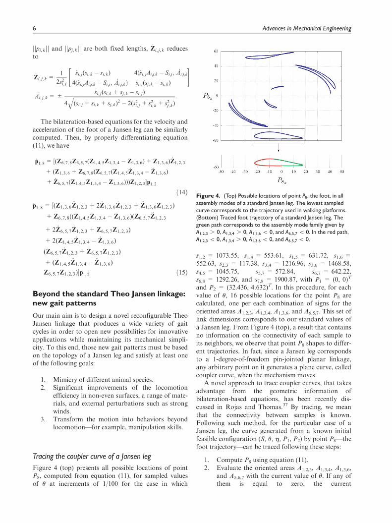
Figure 4 (top) presents all possible locations of pointP8, computed from equation (11), for sampled valuesof u at increments of 1/100 for the case in which
s1,2 = 1073.55, s1,4 = 553.61, s1,5 = 631.72, s1,6 =552.63, s2,3 = 117.38, s3,4 = 1216.96, s3,6 = 1468.58,s4,5 = 1045.75, s5,7 = 572.84, s6,7 = 642.22,s6,8 = 1292.26, and s7,8 = 1900.87, with P1 = (0, 0)T
and P2 = (32.436, 4.632)T. In this procedure, for eachvalue of u, 16 possible locations for the point P8 arecalculated, one per each combination of signs for theoriented areas A1,2,3, A1,3,4, A1,3,6, and A6,5,7. This set oflink dimensions corresponds to our standard values ofa Jansen leg. From Figure 4 (top), a result that containsno information on the connectivity of each sample toits neighbors, we observe that point P8 shapes to differ-ent trajectories. In fact, since a Jansen leg correspondsto a 1-degree-of-freedom pin-jointed planar linkage,any arbitrary point on it generates a plane curve, calledcoupler curve, when the mechanism moves.
A novel approach to trace coupler curves, that takesadvantage from the geometric information ofbilateration-based equations, has been recently dis-cussed in Rojas and Thomas.37 By tracing, we meanthat the connectivity between samples is known.Following such method, for the particular case of aJansen leg, the curve generated from a known initialfeasible configuration (S, u, h, P1, P2) by point P8—thefoot trajectory—can be traced following these steps:
1. Compute P8 using equation (11).2. Evaluate the oriented areas A1,2,3, A1,3,4, A1,3,6,
and A5,6,7 with the current value of u. If any ofthem is equal to zero, the current
Figure 4. (Top) Possible locations of point P8, the foot, in allassembly modes of a standard Jansen leg. The lowest sampledcurve corresponds to the trajectory used in walking platforms.(Bottom) Traced foot trajectory of a standard Jansen leg. Thegreen path corresponds to the assembly mode family given byA1,2,3 . 0, A1,3,4 . 0, A1,3,6 \ 0, and A6,5,7 \ 0. In the red path,A1,2,3 \ 0, A1,3,4 . 0, A1,3,6 \ 0, and A6,5,7 \ 0.
6 Advances in Mechanical Engineering
configuration—that is, the current tuple (S, u,h, P1, P2)—belongs to more than one family ofassembly modes (combinations of signs of theoriented areas A1,2,3, A1,3,4, A1,3,6, and A5,6,7),and the leg movement may evolve along differ-ent paths. Identify all these families, that is,determine all feasible values that h can assume.
3. Increase u at a specified rate. When u reachesthe limit imposed by the triangular inequalitiesassociated with DP1P2P3, DP1P3P4, andDP1P3P6, start to decrease the variable.
4. Repeat steps 1–3 for each tuple (S, u, h,P1, P2)until the whole range of u has been evaluated.
In a standard Jansen leg, the foot trajectory used inwalking platforms—the lowest sampled curve inFigure 4 (top)—can be easily traced following theabove procedure from any u between 0 and p withA1,2,3 . 0, A1,3,4 . 0, A1,3,6 \ 0, and A5,6,7 \ 0. Thecorresponding result is depicted in Figure 4 (bottom).It is interesting to note that the standard foot trajectoryof a Jansen leg resembles to the plantigrade locomotionof some terrestrial animals. In fact, this trajectory isquite similar to those of the ankles of rats duringsingle-step cycles.39
Finding the new gait patterns
According to Kuo et al.,40 a linkage can be consideredas reconfigurable if during its operation at least one ofthe following features varies: (a) the effective numberof links and/or joints, (b) the kinematic type—that is,the contact constraint—of some joints, (c) the adja-cency and incidence of links and joints, and (d) the rela-tive arrangement between joints, or more generally, therelative geometrical relation between joints and links.An interesting consideration for designing reconfigur-able mechanisms is that by simply reallocating the jointpositions of pin-jointed planar linkages, all types ofreconfiguration characteristics, excepting the change ofcontact constraints in kinematic pairs, may beobtained.41
In the case of 1-degree-of-freedom pin-jointed pla-nar linkages, it is well known that a change in the linkdimensions, that is, a modification in the relative dis-tance between connected joints, a reallocation of jointpositions, generates new and different coupler curves.With this basic principle in mind, our approach toobtain novel gait patterns of a Jansen leg is to identifywhether by performing small variations in the lengthsof the links, interesting foot trajectories can beobtained. To this end, a simple exploratory designstudy is suggested: vary the standard dimensions of thelinks in 6 20%, first link by link, later in couples, andfinally in trios, and register the resulting couplercurves—computed using the discussed procedure—to
detect useful gait cycles for future innovative applica-tions in robotics. Following the proposed scheme, wepresent here five gait patterns that extend the capabil-ities of the original Jansen leg, generated through mini-mal changes of link dimensions. Next, each of them isdescribed.
Digitigrade locomotion (cat walking). The standard foot tra-jectory of a Jansen leg corresponds to a kind of planti-grade locomotion. A plantigrade is an animal thatstands or walks with its podials, such as humans regu-larly do—an experimental analysis and characterizationof the human straight walking can be found in Li andCeccarelli.42 In contrast, digitigrades walk on theirdigits or toes. Example of these kind of animals includedogs, cats, many other mammals, and most birds. Sincein each step of digitigrades less foot is touching the sur-face, these animals present less friction and waste ofenergy than plantigrades. In consequence, digitigradestend to be very fast runners.43 This fact makes digiti-grade locomotion of great interest for the developmentof walking platforms.
Table 1 depicts the foot trajectory of a Jansen legwhen the length of the binary link connecting the revo-lute joint centers P5 and P7 is increased by 20% withrespect to its standard value in first row, column‘‘Single link.’’ The shape of this curve is quite similar tothe gait cycle of a cat (see Figure 2 in Lacquaniti etal.44). This result is relevant because it shows that bymodifying the link dimensions of a standard Jansenleg, that is, by reconfiguring a 1-degree-of-freedommechanism, we can switch from a plantigrade locomo-tion to a digitigrade locomotion. Columns ‘‘couple oflinks’’ and ‘‘trio of links’’ in the first row of Table 1present other modifications in the link dimensions thatfurther yield digitigrade behaviors. The foot trajectoriesof the combinations with the H symbols in the columnsare depicted. In each of these figures, the gait of thestandard Jansen leg is presented for reference as a blackcurve. These conventions apply in all next cases.
Obstacle avoidance. The height of the foot trajectory of astandard Jansen leg is 9.38 units (Figure 4), that is, a16.26% of the total height of the leg, a value computedfrom the grounded revolute joint center P1 = (0, 0)T tothe lowest point of the foot trajectory. Therefore, awalking platform based on standard Jansen legs cannotin principle overpass obstacles higher than this limit(.9.38 units). This is an important drawback becausealthough a Jansen-based system is highly efficient, itsoperability in rough terrain is reduced.
Second row, column ‘‘Single link,’’ of Table 1 showsthe foot trajectory of a Jansen leg when the side lengthassociated with points P7 and P8 of the coupler linkDP6P7P8 is decreased by 20% with respect to its
Nansai et al. 7
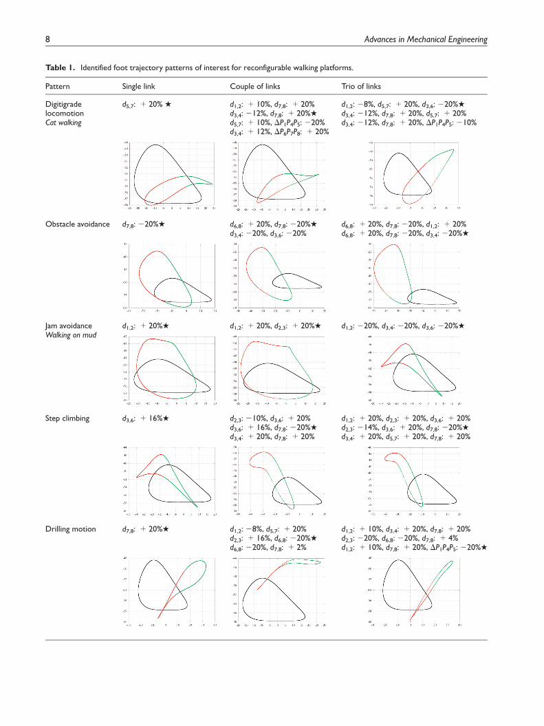
Table 1. Identified foot trajectory patterns of interest for reconfigurable walking platforms.
Pattern Single link Couple of links Trio of links
DigitigradelocomotionCat walking
d5,7: + 20% H d1,2: + 10%, d7,8: + 20%d3,4: 212%, d7,8: + 20%H
d5,7: + 10%, DP1P4P5: 220%d3,4: + 12%, DP6P7P8: + 20%
d1,2: 28%, d5,7: + 20%, d3,6: 220%H
d3,4: 212%, d7,8: + 20%, d5,7: + 20%d3,4: 212%, d7,8: + 20%, DP1P4P5: 210%
Obstacle avoidance d7,8: 220%H d6,8: + 20%, d7,8: 220%H
d3,4: 220%, d3,6: 220%d6,8: + 20%, d7,8: 220%, d1,2: + 20%d6,8: + 20%, d7,8: 220%, d3,4: 220%H
Jam avoidanceWalking on mud
d1,2: + 20%H d1,2: + 20%, d2,3: + 20%H d1,2: 220%, d3,4: 220%, d3,6: 220%H
Step climbing d3,6: + 16%H d2,3: 210%, d3,6: + 20%d3,6: + 16%, d7,8: 220%H
d3,4: + 20%, d7,8: + 20%
d1,2: + 20%, d2,3: + 20%, d3,6: + 20%d2,3: 214%, d3,6: + 20%, d7,8: 220%H
d3,4: + 20%, d5,7: + 20%, d7,8: + 20%
Drilling motion d7,8: + 20%H d1,2: 28%, d5,7: + 20%d2,3: + 16%, d6,8: 220%H
d6,8: 220%, d7,8: + 2%
d1,2: + 10%, d3,4: + 20%, d7,8: + 20%d2,3: 220%, d6,8: 220%, d7,8: + 4%d1,2: + 10%, d7,8: + 20%, DP1P4P5: 220%H
8 Advances in Mechanical Engineering
standard value. In this case, the height of the foot tra-jectory is 21.91 units, that is, a 36.74% of the totalheight of the leg. This new height is more than twicethe foot trajectory of a standard Jansen leg. This recon-figurability characteristic could be of interest for appli-cations in uneven terrains—think, for instance, in ateam of walking platforms for space exploration mis-sions, that is, exploration of asteroids, comets, planets,and so on. Similar obstacle avoidance patterns can beobtained by simultaneously changing different linklengths of a Jansen leg. These results are presented inthe second row, columns ‘‘Couple of links’’ and ‘‘Trioof links,’’ of Table 1.
Jam avoidance (walking on mud). In soft terrains, walkerscan easily get stuck because of the soil conditions. Toovercome such situations, a change in the walker’s gaitcycle has to be introduced, a versatility that a walkingplatform based on standard Jansen legs does not offerin its current form. For example, in a transition from adry soil to a semi-wet mud terrain, the typical foot tra-jectory of a Jansen leg seems inadequate because of therigidity variation of the soil in the two scenarios. A gaitwith the potential to solve this issue is depicted in thethird row, column ‘‘single link,’’ of Table 1. Such curveis obtained by increasing 20% the distance between thegrounded revolute joint centers P1 and P2. Beyond itsheight, this type of trajectory is of interest because fac-ing the soil with an arc shape, while maintaining a steplength close to the original one, allows to extract mate-rial and look for a suitable support point at the sametime. As in the other reconfigurability characteristicspreviously discussed, similar jam avoidance patternscan be obtained by simultaneously changing differentlink lengths of a Jansen leg. The corresponding combi-nations of link dimensions are presented in the thirdrow, columns ‘‘Couple of links’’ and ‘‘Trio of links’’ ofTable 1.
Step climbing. Fourth row of Table 1 presents the modi-fications in the link dimensions of a standard Jansenleg that yield foot trajectories for climbing steps. Thiscurve results from increasing 16% the distance betweenthe grounded revolute joint centers P3 and P6. Thesegamma-like patterns are more appropriate for climbingsteps than the normal foot trajectory due to the signifi-cantly shorter contact line with the floor—think, forexample, the length of the steps.
Drilling motion. In kinematics of mechanisms, reciprocat-ing motion is in general defined as a recurrentup-and-down or back-and-forth movement. It is nor-mally associated with a repetitive straight-line motionresulting from or giving rise to a full rotation. In
complex 1-degree-of-freedom planar linkages, that is,mechanisms with coupler curves of order much higherthan six, the degree of a four-bar linkage coupler curve,such standard concept should be extended becauseoverlapping motions different to a straight line can beobtained in specific ranges of the input joint. An exam-ple of this kind of reciprocating motion in a double but-terfly linkage, a mechanism whose coupler curves canreach order 48, is presented in Rojas and Thomas.45
Observe that this behavior also occurs in a standardJansen leg as it can be verified in the sampled curvespresented in Figure 4 (top).
Fifth row of Table 1 presents the modifications inthe link dimensions of a standard Jansen leg that yieldfoot trajectories with reciprocating characteristics.These curves, product of increasing 20% the distancebetween the joint center P7 and the foot point P8 forthe case of single-link modification, are of interestbecause their needle-like shapes can be used for drillingactivities. With this resulting reconfigurability charac-teristic, we go one step further because it shows that byvarying the link dimensions of a standard Jansen leg,we can, in addition to modify the gait patterns of thewalking platform, change the behavior of the system.In this case, from a walker to a driller.
Characterization of leg transformation
We have shown so far that by changing the link dimen-sions of a standard Jansen leg, a variety of gait patternsof interest for innovative applications in robotics canbe identified, that is, digitigrade locomotion, obstacleavoidance, jam avoidance, step climbing, and drillingmotion. An important design challenge is how to per-form a proper transformation between gait patterns.By proper we mean, for example, that undesired floorcontacts must be avoided during the transformationprocess. Note that the answer to this question hasimplications in the control and design of the proposedJansen leg with variable link dimensions.
Following the above discussion, we have devised asimple procedure for transforming a reconfigurableJansen leg from a pattern A to a pattern B, where bothA and B are different and belong to the set of patterns(plantigrade locomotion, digitigrade locomotion,obstacle avoidance, jam avoidance, step climbing, anddrilling motion) as described in Section ‘‘Beyond thestandard Theo Jansen linkage: new gait patterns.’’ As aproof of concept, we consider the transformation fromdigitigrade locomotion (d5,7: +20%) to step climbing(d3,6: +16%). The proposed method is as follows:
1. For pattern A, from the current location of thegrounded revolute joint centers P1 and P2,determine the lowest value of P8y
and the
Nansai et al. 9
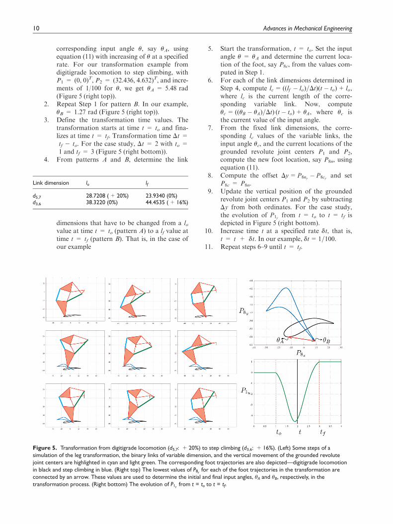
corresponding input angle u, say uA, usingequation (11) with increasing of u at a specifiedrate. For our transformation example fromdigitigrade locomotion to step climbing, withP1 = (0, 0)T, P2 = (32.436, 4.632)T, and incre-ments of 1/100 for u, we get uA = 5.48 rad(Figure 5 (right top)).
2. Repeat Step 1 for pattern B. In our example,uB = 1.27 rad (Figure 5 (right top)).
3. Define the transformation time values. Thetransformation starts at time t = to and fina-lizes at time t = tf. Transformation time Dt =tf 2 to. For the case study, Dt = 2 with to =1 and tf = 3 (Figure 5 (right bottom)).
4. From patterns A and B, determine the link
dimensions that have to be changed from a lovalue at time t = to (pattern A) to a lf value attime t = tf (pattern B). That is, in the case ofour example
5. Start the transformation, t = to. Set the inputangle u = uA and determine the current loca-tion of the foot, say P8c, from the values com-puted in Step 1.
6. For each of the link dimensions determined inStep 4, compute lc =((lf � lo)=Dt)(t � to)+ lo,where lc is the current length of the corre-sponding variable link. Now, computeuc =((uB � uA)=Dt) (t � to)+ uA, where uc isthe current value of the input angle.
7. From the fixed link dimensions, the corre-sponding lc values of the variable links, theinput angle uc, and the current locations of thegrounded revolute joint centers P1 and P2,compute the new foot location, say P8n, usingequation (11).
8. Compute the offset Dy=P8ny� P8cy
and setP8c = P8n.
9. Update the vertical position of the groundedrevolute joint centers P1 and P2 by subtractingDy from both ordinates. For the case study,the evolution of P1y
from t = to to t = tf isdepicted in Figure 5 (right bottom).
10. Increase time t at a specified rate dt, that is,t = t + dt. In our example, dt = 1=100.
11. Repeat steps 6–9 until t = tf.
Link dimension lo lf
d5,7 28.7208 (+ 20%) 23.9340 (0%)d3,6 38.3220 (0%) 44.4535 (+ 16%)
Figure 5. Transformation from digitigrade locomotion (d5,7: + 20%) to step climbing (d3,6: + 16%). (Left) Some steps of asimulation of the leg transformation, the binary links of variable dimension, and the vertical movement of the grounded revolutejoint centers are highlighted in cyan and light green. The corresponding foot trajectories are also depicted—digitigrade locomotionin black and step climbing in blue. (Right top) The lowest values of P8y
for each of the foot trajectories in the transformation areconnected by an arrow. These values are used to determine the initial and final input angles, uA and uB, respectively, in thetransformation process. (Right bottom) The evolution of P1y
from t = to to t = tf.
10 Advances in Mechanical Engineering

This procedure is summarized in the flowchart pre-sented in Figure 6. Figure 5 (left) shows some steps of asimulation of the leg transformation from digitigradelocomotion (d5,7: +20%) to step climbing (d3,6:+16%). The binary links of variable dimension andthe vertical movement of the grounded revolute jointcenters are highlighted in cyan and light green.
Implementation of a reconfigurableJansen leg
Figure 7 (center) presents the complete CAD design ofa fully functional reconfigurable Jansen leg with fouractuators suitable for the transformation procedure dis-cussed in section ‘‘Characterization of leg transforma-tion.’’ In this design, we consider transformations ofpatterns by changing the lengths of single links, that is,link combinations presented in column ‘‘single link’’ ofTable 1. Note that for such transformations, only fourlength variables are needed, namely, d1,2, d3,6, d5,7, andd7,8. In this design, the extendable links, which can bemodeled as a revolute–prismatic–revolute kinematicchain with an actuated slider joint, correspond to linearactuators utilizing ball screw with two hinge holes at itsends. The base link is designed to allow the up anddown movement of the reconfigurable Jansen leg asrequired by the transformation procedure. Next, suchconceptions are detailed.
Extendable links
From Table 1, it is known that the binary links associ-ated with the length variables d1,2, d3,6, d5,7, and d7,8have to be changed from standard size (0%) to 220%,+16%, and +20% for obtaining the multiple gaitpatterns: plantigrade locomotion, digitigrade locomo-tion, obstacle avoidance, jam avoidance, step climbing,and drilling motion. The linear actuator for theseextendable links can be designed to uniquely satisfythese specific requirements, that is, a linear actuatorwith a discrete number of positions, but, thinking infuture works where other modifications may be neces-sary, a solution with a continuous set of positions ispreferred. Moreover, the proposed design should beable to change the link dimension without run off theedge where the two revolute joint centers are located(the hinge holes) because it might generate undesirablecontacts between other links in the linkage as it couldhappen if, for example, the module for reconfigurationby reallocation of joint positions in pin-jointed planarlinkages suggested in Rojas et al.41 is used.
Details of the extendable links designed to satisfythe described conditions can be observed in theexploded view presented in Figure 7 (top). The pro-posed design is based on a ball screw with a motor
properly installed in parallel utilizing gears. Since ballscrews tend to back drive because of their low friction,for simplicity, we opted to use motors of high torqueand low speed instead of implementing a brake in thesystem in order to hold the link dimensions. A proto-type of this design using a direct current (DC) motor(SPG30E-300K, rated torque: 1176 N mm, ratedspeed: 12 r/min) and aluminum is shown in Figure 8(left). It can be verified through simulation that thehighest back-drive torques—that is, torque required tosupport a load in position in a screw—during locomo-tion are lower than 15.92 N mm (� 1176Nmm). Asan alternative, motors with a low/high relationshipbetween torque and speed can be used to improve theefficiency of the system, but in this case, the extendable
Figure 6. Flowchart of the proposed method for legtransformation (see text for details).
Nansai et al. 11

link design should include a non-backdrivable mechan-ism for avoiding undesired changes in the link dimen-sions during normal operation.
Base system
In order to realize the transformation process withoutfloor contacts as discussed in section ‘‘Characterizationof leg transformation,’’ the reconfigurable Jansen leghas to be moved up and down. The easiest way to solvethis is to install a linear actuator in the base link, takinginto account that such base system must support the
moment of the whole mechanism. Observe that if themoment is applied directly to the linear actuator, itsmotion could be affected and, in the worst case, the sys-tem could break. To avoid this, two straight guides aredesigned to support the base link and its up-and-downmovement. The base link and in consequence the recon-figurable Jansen leg are fixed to the guides by fourpoints, two in each guide, which are connected to thelinear actuator.
Details of the base system design can be observed inthe exploded view presented in Figure 7 (bottom). Aprototype of this design is shown in Figure 8, in which
Figure 7. A fully functional reconfigurable Jansen leg with four linear actuators suitable for the transformation procedurepresented in section ‘‘Characterization of leg transformation’’ (link combinations presented in column ‘‘single link’’ of Table 1)(center). Zoomed areas present the base system (center right) and links of variable dimension—extendable links (center left).Details of these designs can be observed in the corresponding exploded views—base system (bottom) and extendable links (top).
12 Advances in Mechanical Engineering

a DC motor (RG50M775245000-120K, rated torque:4.9 N m, rated speed: 30 r/min) was installed for driv-ing the reconfigurable linkage. Since it has been shownthat a torque of 1 N m is necessary to drive the Jansenleg at a constant speed;46 the selected motor has a safetyfactor of 4.9, a value high enough to resist variations inthe torque requirement resulting from, for instance,errors in the parameters.
The base system and extendable links are the princi-pal components of the proposed design of a reconfigur-able Jansen leg. Figure 1 presents a working prototypeof this mechanism. This implementation uses acrylic forthe links of fixed dimension and has been carried out inthe SUTD Fabrication Lab using a minimum amountof off-the-shelf parts. In the next section, some resultsobtained with this prototype are discussed.
Performance
Effectiveness of the design and prototype of the recon-figurable Jansen leg presented in section‘‘Implementation of a reconfigurable Jansen leg,’’ forgenerating the multiple gait patterns—section ‘‘Beyondthe standard Theo Jansen linkage: new gait patterns’’—as well as the proposed transformation process—section ‘‘Characterization of leg transformation’’—wasverified through experimentation. In the experiments,the linear actuators of the reconfigurable Jansen legwere driven at constant speed by proportional–inte-gral–derivative (PID) controllers (gains: P = 50,I = 0.008, and D = 0.01), ideal trajectories were
generated using the procedure of Figure 6. The result-ing leg trajectories were obtained using image process-ing tools. For measuring the rotation angle of eachmotor, rotary encoders, utilizing hole sensors, wereinstalled and ‘‘Arduino MEGA 2560’’ was used as con-trol CPU. The obtained experimental results are dis-cussed next.
Generation of gait patterns
The first experiment consisted in comparing the simu-lated and experimental leg trajectories for the differentgait patterns. To this end, the link dimensions of thereconfigurable Jansen leg were set according to the linkcombinations presented in column ‘‘single link’’ ofTable 1 for then actuating the input joint (motor) for10 cycles. The results of this process are shown inFigure 9 for the gait patterns plantigrade locomotion(standard trajectory of a Jansen leg), digitigrade loco-motion, obstacle avoidance, step climbing, and drillingmotion. After experimentation, it was discovered thatthe jam avoidance pattern cannot be generated with thecurrent prototype because when the angle between theinput link (corresponding to the line segment P2P3 inFigure 2) and the base link (line segment P1P2) is3.1 rad, the distance between the revolute joint centersP1 and P7 is 2.07 cm, a value that exceeds the minimumable to be reproduced with the current implementation(6.32 cm). Future developments of the reconfigurableJansen leg will resolve this limitation by thinning thestructure surrounding the link pin holes.
Figure 8. Prototypes of the base system (right) and extendable links (left).
Nansai et al. 13

Figure 9. Comparison between the simulated leg trajectory (in gray) and the average experimental trajectory (in red) obtainedafter 10 cycles of the input joint (curves depicted in black) for the gait patterns plantigrade locomotion (standard trajectory of aJansen leg), digitigrade locomotion, obstacle avoidance, step climbing, and drilling motion.
14 Advances in Mechanical Engineering

Table 2 shows the error and percent error of com-paring the width and height of the average experimen-tal trajectory with those of the simulated trajectory, foreach of the gait patterns presented in Figure 9. A per-cent error of less than 22% is obtained for all cases butthe step climbing pattern. The origin of such errors isprincipally due to the non-conformity of link lengthsand the presence of joint clearances in the prototype.Both error sources are almost inherent to the fabrica-tion of mechanical designs and are the typical elementsthat affect the performance of linkages and mechan-isms.47 The big error in the step climbing pattern,40.01% in height, is given by the greater moment gen-erated by the mechanism. It can be easily shown bysimulation that the farthest center of mass point, withrespect to the base link, is achieved in such pattern, asa consequence, the joint clearance (backlash effect)affects more this pattern than the others. Table 2 alsopresents the standard deviation of the experimental legtrajectories for each of the evaluated patterns; in allcases, these values are small, showing the good repeat-ability of the developed prototype.
The above experimental validation is completed bythe results presented in Figure 10, in which a compari-son between the simulated speed at the foot point, mag-nitude of the velocity vector of equation (14), and theaverage experimental speed, computed from the aver-age experimental trajectory (Figure 9), is presented forthe gait patterns plantigrade locomotion, digitigradelocomotion, obstacle avoidance, step climbing, anddrilling motion. For all these cases, the obtained resultsand corresponding mean-squared errors prove the ade-quate generation of gait patterns of the reconfigurableJansen leg prototype.
Leg transformation
The second experiment consisted in verifying the trans-formation process presented in Section‘‘Characterization of leg transformation.’’ To this end,
the transformation from plantigrade locomotion tostep climbing was tested. In this experiment, the starttime of transformation was set to to = 3.0 s with atransformation time of Dt = 180 s. Figure 11 showssome snapshots of the experiment, highlighting the cor-responding leg trajectories during the process. Theresults verify that the transformation is carried outwithout undesired floor contacts.
Conclusion
Since 1-degree-of-freedom planar leg mechanisms arecontrolled using a single rotary actuator, legged robotsbased on these linkages are energy efficient with simplegait control. However, the locomotion capabilities ofthese robots are limited because their legs are con-strained to follow a unique gait pattern. With the pur-pose to overcome this problem, in this article, we haveintroduced an original design approach to achieveadaptive gait patterns in legged robots for which 1-degree-of-freedom closed kinematic chains form thecore. In particular, we have modified a Theo Jansenlinkage, a 1-degree-of-freedom leg mechanism widelyadopted in walking platforms, to produce a wide vari-ety of gait cycles using the reconfiguration principle ofvariable allocation of joint positions. In the proposeddesign, during the reconfiguration process, the systemswitches from the pin-jointed topology of the standardJansen linkage (a Grubler kinematic chain) to a 5-degree-of-freedom mechanism with four slider joints.
We have discussed novel approaches to address theposition analysis problem and to characterize leg trans-formation in this reconfigurable design. Five gait pat-terns of interest, namely, digitigrade locomotion,obstacle avoidance, jam avoidance, step climbing, anddrilling motion, have been identified, analyzed, and dis-cussed in relation to potential future applications.These exemplary gait variations considerably extendthe capabilities of the original design not only to pro-duce novel gait patterns but also to realize behaviors
Table 2. Numerical analysis of experiment results.
Pattern Simulation (cm) Experiment (cm) Error (cm) Percent error (%) Standarddeviation (cm)
Plantigrade locomotion Width 39.82 33.42 6.40 16.07 0.47Height 9.39 7.59 1.79 19.12
Digitigrade locomotion Width 39.97 33.40 6.57 16.45 0.63Height 4.64 3.66 0.98 21.15
Obstacle avoidance Width 36.48 30.01 6.47 17.74 0.67Height 21.92 18.59 3.32 15.16
Step climbing Width 39.17 32.46 6.71 17.17 0.41Height 13.23 7.94 5.29 40.01
Drilling motion Width 39.05 33.08 5.97 15.27 0.52Height 10.90 9.00 1.90 17.41
Nansai et al. 15

Figure 10. Comparison between the simulated speed at the foot point (in black)—that is, magnitude (Euclidean norm) of equation(14)—and the average experimental speed (in red) computed from the average experimental trajectory (Figure 9) for the gaitpatterns plantigrade locomotion (standard trajectory of a Jansen leg), digitigrade locomotion, obstacle avoidance, step climbing, anddrilling motion.
Figure 11. Experimental transformation process from plantigrade locomotion to step climbing (d5,7: + 20%). (Top) Snapshots ofthe experiment. A green marker, circled by a red line, located at the foot point is tracked. The green and red trajectories representthe plantigrade locomotion pattern and the step climbing pattern, respectively. The white line represents an estimated ground; it iscomputed because the prototype is tilted due to an inclination in the base system. The small red circle represents the origin of thereference frame. (Bottom left) Zoomed view of the tracked trajectories. (Bottom right) Rotated experimental leg trajectories inwhich the ground line is parallel to the x axis of the reference frame. The resulting curve during the transformation process is shownin blue.
16 Advances in Mechanical Engineering

beyond locomotion. In the proposed reconfigurableJansen leg, the linear actuators added to the systemhave to be only controlled during the transformationoperation between gait patterns, thus maintaining themechanical simplicity of the original design during nor-mal operation. A fully functional design of a reconfi-gurable Jansen leg has been presented and experimentalresults with a working prototype have been reported.
A four-legged robot is currently being assembledwith reconfigurable Jansen legs based on the designherein discussed. The objective with this robot is to testdifferent reconfiguration scenarios and control strate-gies for limb specialization and graceful degradation.Our long-term aim is to develop systematic methods todesign reconfigurable robots capable of transformingin response to needs associated with environment, task,or failures.
Acknowledgement
The authors gratefully acknowledge the assistance of ChooPoh Jim, Sunardi Tay, Raymond Yeong, and Takuya Sasaiin the prototyping and experimentation of the reconfigurableJansen leg reported in this work. This article was presented inpart at the 2013 IEEE/RSJ International Conference onIntelligent Robots and Systems, Tokyo, Japan, November 3–7 2013.
Declaration of conflicting interests
The authors declare that there is no conflict of interest.
Funding
This research was supported by the SUTD-MIT InternationalDesign Center under grants IDG31200110 and IDD41200105and by the SUTD-ZJU Research Center.
References
1. Sitti M, Menciassi A, Ijspeert A, et al. Survey and intro-
duction to the focused section on bioinspired mechatro-
nics. IEEE ASME Trans Mechatron 2013; 18(2):
409–418.2. Tsujita K, Kobayashi T, Inoura T, et al. Gait transition
by tuning muscle tones using pneumatic actuators in
quadruped locomotion. In: IEEE/RSJ international con-
ference on intelligent robots and systems, Nice, 22–26 Sep-
tember 2008, pp.2453–2458. New York: IEEE.3. Chen X, Wang L-Q, Ye X-F, et al. Prototype develop-
ment and gait planning of biologically inspired multi-
legged crablike robot. Mechatronics 2013; 23(4): 429–444.4. Kamimura A, Kurokawa H, Yoshida E, et al. Automatic
locomotion design and experiments for a modular
robotic system. IEEE ASME Trans Mechatron 2005;
10(3): 314–325.5. Sun Y, Ma S, Yang Y, et al. Towards stable and efficient
legged race-walking of an ePaddle-based robot. Mecha-
tronics 2013; 23(1): 108–120.
6. Paul C, Roberts JW, Lipson H, et al. Gait production in
a tensegrity based robot. In: 12th IEEE international con-
ference on advanced robotics, Seattle, WA, 18–20 July
2005, pp.216–222. New York: IEEE.7. Hutter M, Remy C, Hoepflinger M, et al. Efficient and
versatile locomotion with highly compliant legs. IEEE
ASME Trans Mechatron 2013; 18(2): 449–458.8. Paul C. Morphological computation: a basis for the anal-
ysis of morphology and control requirements. Robot
Auton Syst 2006; 54(8): 619–630.9. Cham JG, Karpick JK and Cutkosky MR. Stride period
adaptation of a biomimetic running hexapod. Int J Robot
Res 2004; 23(2): 141–153.10. Fukuoka Y, Kimura H and Cohen AH. Adaptive
dynamic walking of a quadruped robot on irregular ter-
rain based on biological concepts. Int J Robot Res 2003;
22(3–4): 187–202.11. Zhang L, Dai J and Yang T. Reconfiguration techniques
and geometric constraints of metamorphic mechanisms.
In: Proceedings of the ASME 2009 international design
engineering technical conferences & computers and infor-
mation in engineering conference, San Diego, CA, 30
August–2 September 2009, paper no. DETC2009-87345,
pp.559–575. New York: ASME.12. Yan H and Kang C. Configuration synthesis of mechan-
isms with variable topologies. Mech Mach Theor 2009;
44(5): 896–911.
13. Li S and Dai JS. Structure synthesis of single-driven
metamorphic mechanisms based on the augmented Assur
groups. J Mech Robot 2012; 4(3): 031004.14. Singh V, Skiles S, Krager J, et al. Innovations in design
through transformation: a fundamental study of transfor-
mation principles. J Mech Des 2009; 131(8): 081010.15. McCarthy J and Soh GS. Geometric design of linkages.
London: Springer, 2011.16. Gogate G and Matekar S. Optimum synthesis of motion
generating four-bar mechanisms using alternate error
functions. Mech Mach Theor 2012; 54: 41–61.17. Burmester L. Lehrbuch der Kinematik. Leipzig: Verlag
Von Arthur Felix, 1888.18. Rubel A and Kaufman R. KINSYN III: a new human-
engineered system for interactive computer-aided design
of planar linkages. J Eng Ind 1977; 99(2): 440–448.19. Lee E and Mavroidis C. Solving the geometric design
problem of spatial 3R robot manipulators using polyno-
mial homotopy continuation. J Mech Des 2002; 124(4):
652–661.
20. Su H, Watson L and McCarthy J. Generalized linear
product homotopy algorithms and the computation of
reachable surfaces. J Comput Inf Sci Eng 2004; 4(3):
226–234.21. Mariappan J and Krishnamurty S. A generalized exact
gradient method for mechanism synthesis. Mech Mach
Theor 1996; 31(4): 413–421.22. Coros S, Thomaszewski B, Noris G, et al. Computational
design of mechanical characters. ACM Trans Graphic
2013; 32(4): 83:1–83:12.23. Lee E and Mavroidis C. An elimination procedure for
solving the geometric design of spatial 3R manipulators.
J Mech Des 2005; 128(1): 142–145.
Nansai et al. 17
24. Pucheta M. Computational methods for the design and
synthesis of planar mechanisms. PhD Thesis, UniversidadNacional del Litoral, Santa Fe, Argentina, 2008.
25. McCarthy J. 21st century kinematics: the 2012 NSF work-
shop. London: Springer, 2013.26. Rojas N. Distance-based formulations for the position
analysis of kinematic chains. PhD Thesis, Institut deRobotica i Informatica Industrial (CSIC-UPC), Universi-tat Politecnica de Catalunya, Barcelona, 2012.
27. Ceccarelli M and Koetsier T. Burmester and Allievi: atheory and its application for mechanism design at theend of 19th century. J Mech Des 2008; 130: 072301.
28. Song S and Waldron KKJ. Machines that walk—the
adaptive suspension vehicle. Cambridge, MA: The MITPress, 1989.
29. Carbone G and Ceccarelli M. Chapter 33. Legged roboticsystems. In: V Kordic, A Lazinica and M Merdan (eds)
Cutting edge robotics. Rijeka: InTech, 2005, pp.553–576.30. Artobolevsky I. Mechanisms in modern engineering
design—a handbook for engineers, designers, and inven-
tors, vol. 1. Moscow, Russia: MIR Publishers, 1975.31. Klann J. Jansen linkage—Klann linkage comparison,
2009, http://www.mechanicalspider.com/comparison.html
32. Jansen T. The great pretender. Rotterdam: 010 Publishers,2007.
33. Komoda K and Wagatsuma H. A study of availabilityand extensibility of Theo Jansen mechanism towardclimbing over bumps. In: Proceedings of the 21st annual
conference of the Japanese neural network society, Oki-nawa, Japan, 15–17 December 2011, paper no. P3-28.Japan: Japanese Neural Network Society.
34. Tsai L.Mechanism design: enumeration of kinematic struc-
tures according to function (Mechanical and aerospaceengineering series). Abingdon: Taylor & Francis, 2001.
35. Wampler C. Solving the kinematics of planar mechanismsby Dixon determinant and a complex-plane formulation.J Mech Des 2001; 123(3): 382–387.
36. Rojas N and Thomas F. On closed-form solutions to theposition analysis of Baranov trusses. Mech Mach Theor
2012; 50: 179–196.
37. Rojas N and Thomas F. Application of distance geome-try to tracing coupler curves of pin-jointed linkages. JMech Robot 2013; 5(2): 021001.
38. Kim S-W, Han S-H and Kim DH. Analysis of a crabrobot based on Jansen mechanism. In: 2011 11th interna-
tional conference on control, automation and systems
(ICCAS), Gyeonggi-do, South Korea, 26–29 October2011, pp.858–860. New York: IEEE.
39. Heng C and De Leon R. Treadmill training enhances therecovery of normal stepping patterns in spinal cord con-tused rats. Exp Neurol 2009; 216(1): 139–147.
40. Kuo C, Dai J and Yan H. Reconfiguration principlesand strategies for reconfigurable mechanisms. In: 1st
ASME/IFToMM international conference on reconfigur-
able mechanisms and robots, London, 22–24 June 2009,pp.1–7. New York: IEEE.
41. Rojas N, Mohan R and Sosa R. Reconfiguration in lin-
kages by variable allocation of joint positions: a modulardesign approach. In: 3rd IFToMM international sympo-
sium on robotics and mechatronics, 2–4 October 2013. Sin-gapore: Research Publishing.
42. Li T and Ceccarelli M. An experimental analysis of humanstraight walking. Front Mech Eng 2013; 8(1): 95–103.
43. Johnson J and Burton J. Animal tracks and signs: track
over 400 animals from big cats to backyard birds.Washington, DC: National Geographic Society, 2008.
44. Lacquaniti F, Grasso R and Zago M. Motor patterns inwalking. Physiology 1999; 14(4): 168–174.
45. Rojas N and Thomas F. A coordinate-free approach totracing the coupler curves of pin-jointed linkages. In:2011 ASME international design engineering technical
conferences & computers and information in engineering
conference, 28–31 August 2011, paper no. DETC2011-48147. Washington, DC: ASME.
46. Nansai S, Mohan R and Iwase M. Dynamic analysis andmodeling of Jansen mechanism. Procedia Eng 2013; 64:1562–1571.
47. Ting K, Zhu J and Watkins D. The effects of joint clear-ance on position and orientation deviation of linkagesand manipulators. Mech Mach Theor 2000; 35(3):391–401.
18 Advances in Mechanical Engineering