
Advancements in Mechanical Strength and Reliability of ...Published in the proceedings of the SPIE...
23
Published in the proceedings of the SPIE Critical Reviews Vol. CR73 Reliability of Optical Fibers and Optical Fiber Systems 20-21 September 1999 Boston, Massachusetts 1 Advancements in Mechanical Strength and Reliability of Optical Fibers G. Scott Glaesemann * Corning Incorporated, Corning, NY 14831 Abstract This paper reviews recent advancements in the area of mechanical reliability of optical fiber, building upon previously published reviews in this area. 1-5 Of particular significance is progress in the area of establishing reliability programs. This review considers efforts made to reduce early failures and to establish reliability programs with an emphasis on functional reliability. Keywords: Optical fiber, strength, reliability 1. Introduction The mechanical reliability of optical fiber has been studied for several decades. In the early days concerns over delayed failure were mitigated by the advent of the loose tube cable design. In recent years those concerns persist due to the proliferation of constricted cable designs like tight buffer and ribbon. In these cases, fiber can experience a complex array of applied stresses. Even for loose tube cable designs fiber is being asked to carry more of the load. Recent changes to GR-20 state, "With the cable subjected to the rated installation load for one hour, fibers shall exhibit a maximum tensile strain of 60 % of the fiber proof strain." 6 Recent strength testing results show that a proof stress level flaw will fail in minutes if loaded to 60% of the proof stress! 7 This demonstrates the need for consensus on mechanical reliability issues. In addition to delayed failure concerns is the issue of fiber failures due to handling induced damage. The explosion of fiber-based components and devices has resulted in significant lengths of fiber being handled on the assembly floor and placed into ever-smaller packages. There is a need for mechanical reliability programs that address both delayed failure issues and fiber handling procedures. The diagram in Figure 1 shows the classic “bathtub” reliability diagram. The goal is to reduce or eliminate early failures and to maximize the useful life of a product by accurately predicting the onset of wear-out. The primary wear-out phenomenon for optical fiber, from a mechanical point of view, continues to be subcritical crack growth or fatigue. Subcritical crack growth studies have traditionally focused on determining crack growth parameters for in-service lifetime predictions. Recently, high speed dynamic fatigue testing has allowed for a clearer understanding of fatigue during typical fiber processing events. 7 High- * Correspondence: Email: [email protected]; Telephone: 607 974 3736; Fax: 607 974 2364
Transcript of Advancements in Mechanical Strength and Reliability of ...Published in the proceedings of the SPIE...
Published in the proceedings of the SPIE Critical Reviews Vol. CR73 Reliability of Optical Fibers and Optical Fiber Systems 20-21 September 1999 Boston, Massachusetts
1
Advancements in Mechanical Strength and Reliability of Optical Fibers
G. Scott Glaesemann*
Corning Incorporated, Corning, NY 14831
Abstract This paper reviews recent advancements in the area of mechanical reliability of optical fiber, building upon previously published reviews in this area.1-5 Of particular significance is progress in the area of establishing reliability programs. This review considers efforts made to reduce early failures and to establish reliability programs with an emphasis on functional reliability. Keywords: Optical fiber, strength, reliability
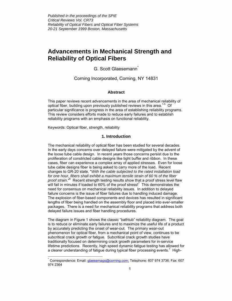
1. Introduction The mechanical reliability of optical fiber has been studied for several decades. In the early days concerns over delayed failure were mitigated by the advent of the loose tube cable design. In recent years those concerns persist due to the proliferation of constricted cable designs like tight buffer and ribbon. In these cases, fiber can experience a complex array of applied stresses. Even for loose tube cable designs fiber is being asked to carry more of the load. Recent changes to GR-20 state, "With the cable subjected to the rated installation load for one hour, fibers shall exhibit a maximum tensile strain of 60 % of the fiber proof strain."6 Recent strength testing results show that a proof stress level flaw will fail in minutes if loaded to 60% of the proof stress!7 This demonstrates the need for consensus on mechanical reliability issues. In addition to delayed failure concerns is the issue of fiber failures due to handling induced damage. The explosion of fiber-based components and devices has resulted in significant lengths of fiber being handled on the assembly floor and placed into ever-smaller packages. There is a need for mechanical reliability programs that address both delayed failure issues and fiber handling procedures. The diagram in Figure 1 shows the classic “bathtub” reliability diagram. The goal is to reduce or eliminate early failures and to maximize the useful life of a product by accurately predicting the onset of wear-out. The primary wear-out phenomenon for optical fiber, from a mechanical point of view, continues to be subcritical crack growth or fatigue. Subcritical crack growth studies have traditionally focused on determining crack growth parameters for in-service lifetime predictions. Recently, high speed dynamic fatigue testing has allowed for a clearer understanding of fatigue during typical fiber processing events.7 High- * Correspondence: Email: [email protected]; Telephone: 607 974 3736; Fax: 607 974 2364
Published in the proceedings of the SPIE Critical Reviews Vol. CR73 Reliability of Optical Fibers and Optical Fiber Systems 20-21 September 1999 Boston, Massachusetts
2
speed processing events like proof testing also are important because they establish the strength distribution that will be subjected to in-service stresses.
Figure 1. The “Reliability Bathtub” diagram from reference 8 There is continued research in characterizing manufacturing and handling induced flaws in optical fiber. Artificially induced flaws continue to be used as a means for understanding their mechanical behavior for two reasons: (1) manufacturing induced flaws are rare and (2) handling induced flaws, though more frequent, do not have sufficiently tight strength distributions. Anyone intimately familiar with manufacturing and handling processes for optical fiber and optical fiber based components knows that most mechanical reliability issues are not related to the technical issues surrounding failure probability predictions from fatigue or aging. The primary issue is one of premature fiber failure caused by handling induced damage or excessive stress. The impact of premature fiber failure for these reasons is shown in Figure 1 as early failures. Early failures have become an increasingly important issue with the high volume
Published in the proceedings of the SPIE Critical Reviews Vol. CR73 Reliability of Optical Fibers and Optical Fiber Systems 20-21 September 1999 Boston, Massachusetts
3
of fiber being handled during cabling and cable installations and the growth of the active and passive fiber component industry. Finally, with new fiber-based telecommunications products being introduced at a staggering pace it seems appropriate to discuss how mechanical reliability programs are established. The key ingredients for establishing a fiber reliability program are presented along with guidance for reducing early failures.
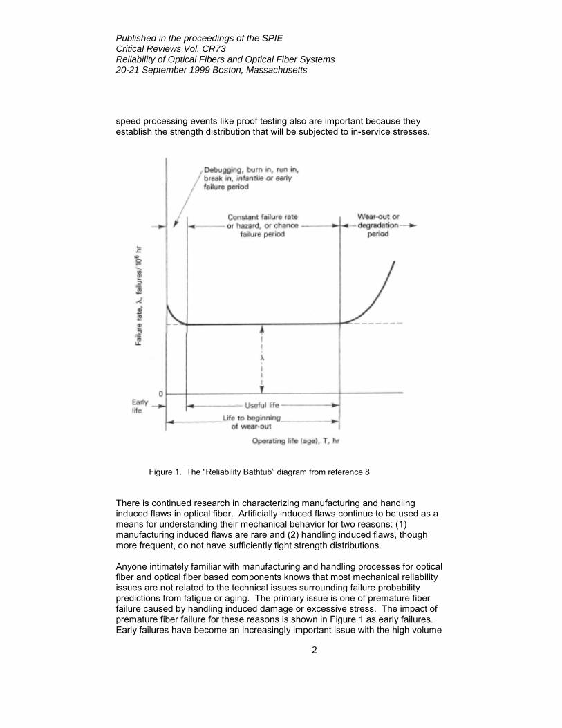
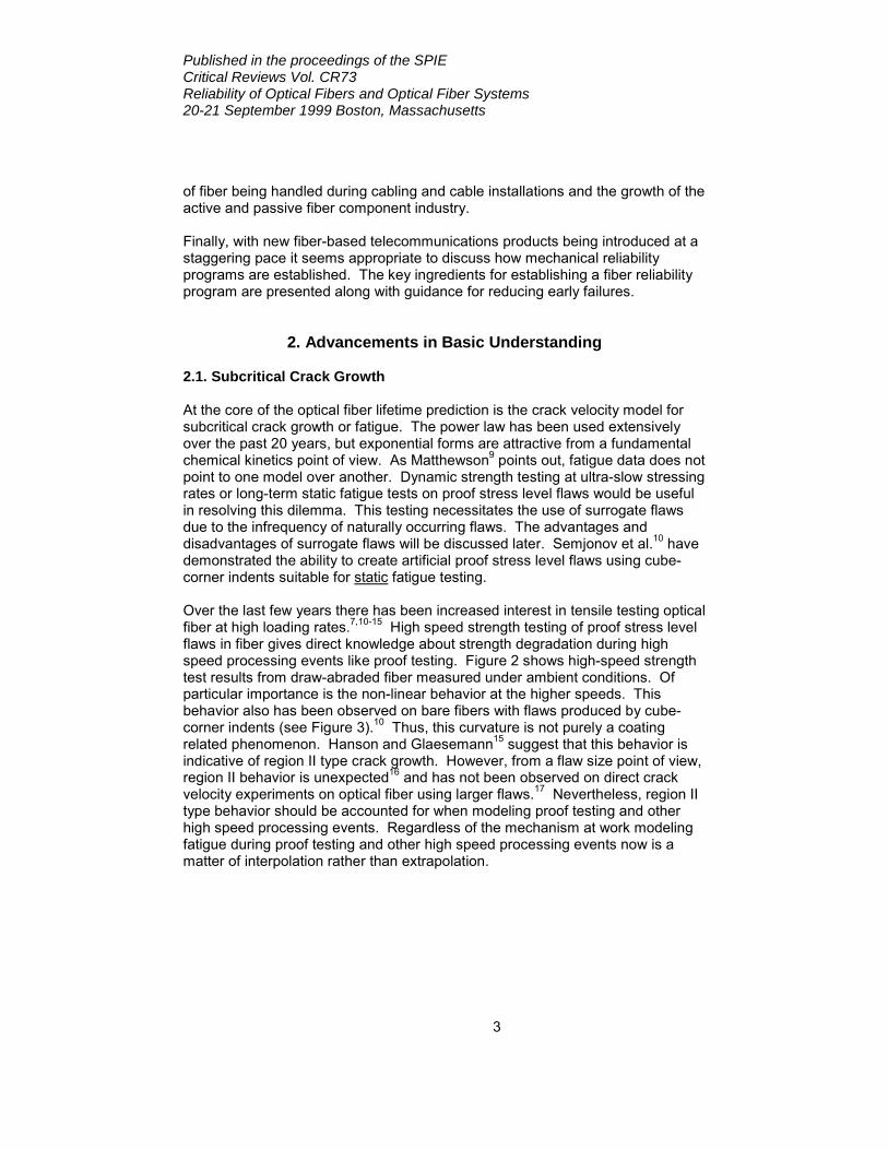
2. Advancements in Basic Understanding 2.1. Subcritical Crack Growth At the core of the optical fiber lifetime prediction is the crack velocity model for subcritical crack growth or fatigue. The power law has been used extensively over the past 20 years, but exponential forms are attractive from a fundamental chemical kinetics point of view. As Matthewson9 points out, fatigue data does not point to one model over another. Dynamic strength testing at ultra-slow stressing rates or long-term static fatigue tests on proof stress level flaws would be useful in resolving this dilemma. This testing necessitates the use of surrogate flaws due to the infrequency of naturally occurring flaws. The advantages and disadvantages of surrogate flaws will be discussed later. Semjonov et al.10 have demonstrated the ability to create artificial proof stress level flaws using cube-corner indents suitable for static fatigue testing. Over the last few years there has been increased interest in tensile testing optical fiber at high loading rates.7,10-15 High speed strength testing of proof stress level flaws in fiber gives direct knowledge about strength degradation during high speed processing events like proof testing. Figure 2 shows high-speed strength test results from draw-abraded fiber measured under ambient conditions. Of particular importance is the non-linear behavior at the higher speeds. This behavior also has been observed on bare fibers with flaws produced by cube-corner indents (see Figure 3).10 Thus, this curvature is not purely a coating related phenomenon. Hanson and Glaesemann15 suggest that this behavior is indicative of region II type crack growth. However, from a flaw size point of view, region II behavior is unexpected16 and has not been observed on direct crack velocity experiments on optical fiber using larger flaws.17 Nevertheless, region II type behavior should be accounted for when modeling proof testing and other high speed processing events. Regardless of the mechanism at work modeling fatigue during proof testing and other high speed processing events now is a matter of interpolation rather than extrapolation.
Published in the proceedings of the SPIE Critical Reviews Vol. CR73 Reliability of Optical Fibers and Optical Fiber Systems 20-21 September 1999 Boston, Massachusetts
4
Stressing Rate, GPa/s
10-5 10-3 10-1 101 103
Stre
ngth
, G
Pa
0.3
0.4
0.5
0.6
0.7
0.8
0.91.01.11.2
Predicted Initial Strength
Measured Fatigue Strength
Predicted Fatigue Strength
(ambient environment)
10-6 10-5 10-4 10-3 10-2 10-1 100 101 102 103 104 105
0.4
0.5
0.6
0.7
0.8
0.9
11
stre
ngth
at R
T / s
tren
gth
in lN
2
testing speed, GPa/s
Figure 3. Median strength of indented fibers with high-speed tester. 10 □ - 1 gram indent; ▲ - 2 gram indent
Figure 2. Measured strength and predicted initial and fatigue strength for abraded optical fiber tested at high speeds7
Published in the proceedings of the SPIE Critical Reviews Vol. CR73 Reliability of Optical Fibers and Optical Fiber Systems 20-21 September 1999 Boston, Massachusetts
5
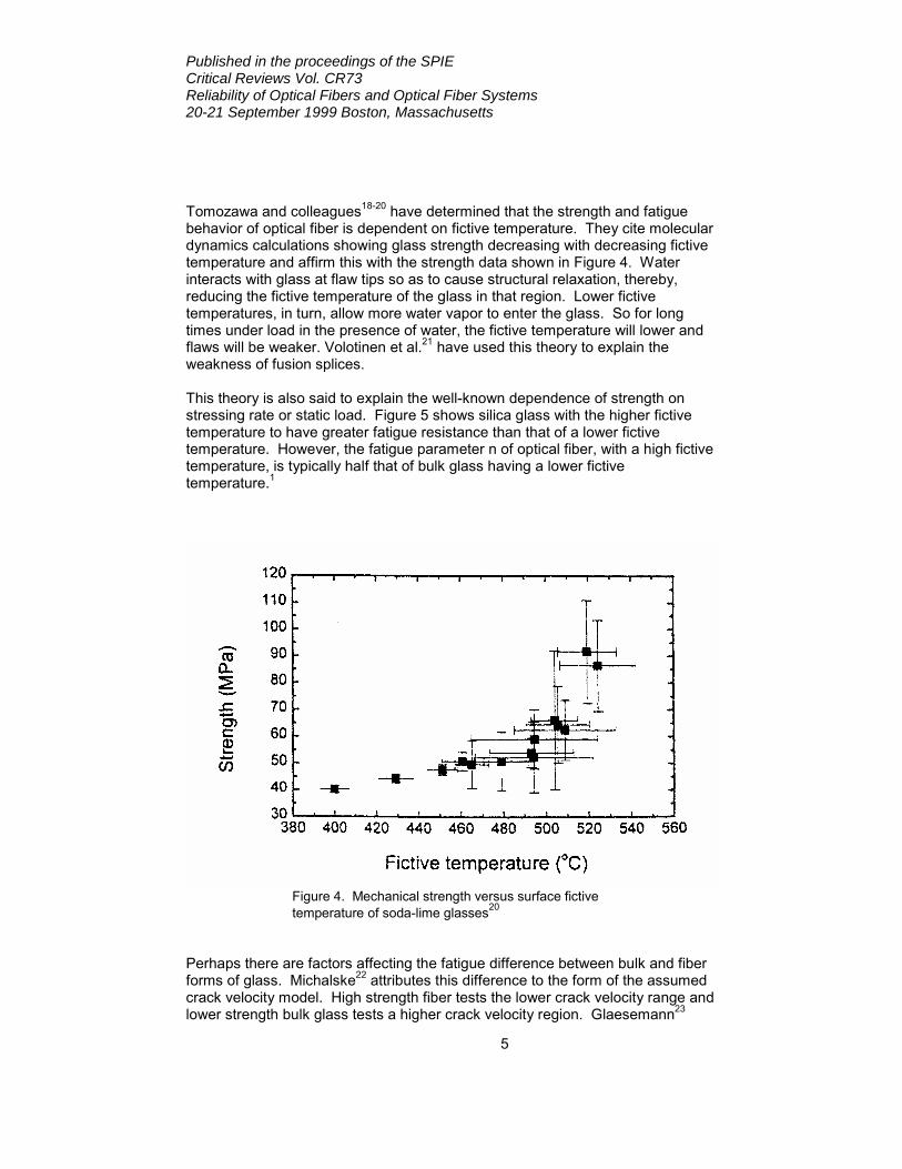
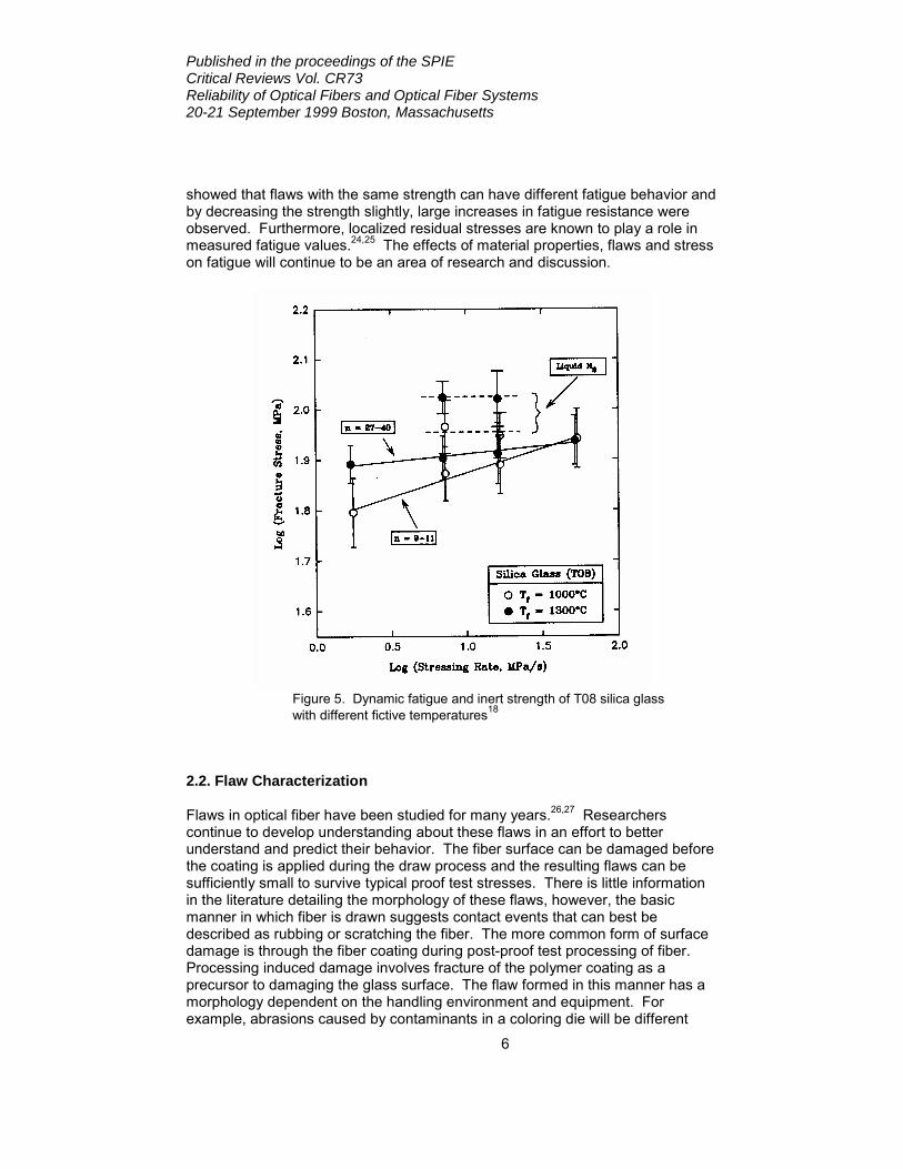
Tomozawa and colleagues18-20 have determined that the strength and fatigue behavior of optical fiber is dependent on fictive temperature. They cite molecular dynamics calculations showing glass strength decreasing with decreasing fictive temperature and affirm this with the strength data shown in Figure 4. Water interacts with glass at flaw tips so as to cause structural relaxation, thereby, reducing the fictive temperature of the glass in that region. Lower fictive temperatures, in turn, allow more water vapor to enter the glass. So for long times under load in the presence of water, the fictive temperature will lower and flaws will be weaker. Volotinen et al.21 have used this theory to explain the weakness of fusion splices. This theory is also said to explain the well-known dependence of strength on stressing rate or static load. Figure 5 shows silica glass with the higher fictive temperature to have greater fatigue resistance than that of a lower fictive temperature. However, the fatigue parameter n of optical fiber, with a high fictive temperature, is typically half that of bulk glass having a lower fictive temperature.1
Figure 4. Mechanical strength versus surface fictive temperature of soda-lime glasses20
Perhaps there are factors affecting the fatigue difference between bulk and fiber forms of glass. Michalske22 attributes this difference to the form of the assumed crack velocity model. High strength fiber tests the lower crack velocity range and lower strength bulk glass tests a higher crack velocity region. Glaesemann23
Published in the proceedings of the SPIE Critical Reviews Vol. CR73 Reliability of Optical Fibers and Optical Fiber Systems 20-21 September 1999 Boston, Massachusetts
6
showed that flaws with the same strength can have different fatigue behavior and by decreasing the strength slightly, large increases in fatigue resistance were observed. Furthermore, localized residual stresses are known to play a role in measured fatigue values.24,25 The effects of material properties, flaws and stress on fatigue will continue to be an area of research and discussion.
Figure 5. Dynamic fatigue and inert strength of T08 silica glass with different fictive temperatures18
2.2. Flaw Characterization Flaws in optical fiber have been studied for many years.26,27 Researchers continue to develop understanding about these flaws in an effort to better understand and predict their behavior. The fiber surface can be damaged before the coating is applied during the draw process and the resulting flaws can be sufficiently small to survive typical proof test stresses. There is little information in the literature detailing the morphology of these flaws, however, the basic manner in which fiber is drawn suggests contact events that can best be described as rubbing or scratching the fiber. The more common form of surface damage is through the fiber coating during post-proof test processing of fiber. Processing induced damage involves fracture of the polymer coating as a precursor to damaging the glass surface. The flaw formed in this manner has a morphology dependent on the handling environment and equipment. For example, abrasions caused by contaminants in a coloring die will be different
Published in the proceedings of the SPIE Critical Reviews Vol. CR73 Reliability of Optical Fibers and Optical Fiber Systems 20-21 September 1999 Boston, Massachusetts
7
than those generated by a damaged pulley. Wiederhorn and Lawn28 state the key variables involved in generating an abrasion flaw to be the relative material properties of the abrasive and target material, the geometry of the abrasive, the localized residual stress generated by the impact event, the fracture toughness of the target material and the kinetic energy imparted during the damage event. Thus, the mechanical damage during processing or handling steps, like stripping, cleaning, cleaving and splicing, can have unique morphologies since the abrasion events vary widely. More recently, Ritter et al.29 claim that for large abrasion flaws in bulk silica glass, the radial crack will always control failure. It is not known if the smaller abrasion type flaws in optical fiber can be generalized in this fashion. A deeper understanding of flaw morphologies related to specific handling events is needed. The other basic flaw type for optical fiber is embedded particles.30 Particulate can be wholly contained within the fiber preform or exist partially embedded on the fiber surface. The origin for such contamination can be the draw environment or surface contamination during splicing events.31 The distinction between internal and external flaw is important in that internal flaws will not grow subcritically over time due to the absence of molecular water. The frequency of these flaws has decreased over the years as manufacturing processes improve, nevertheless, understanding their mechanical behavior is important. Recently, Wissuchek32 modeled residual stresses and stress intensity factors for some common particulate compositions as a first step toward establishing a fracture mechanics model for these flaw types. He demonstrates the residual stress dependence on particle shape and elastic modulus. Furthermore, he concludes that the toughness and fatigue properties of the particle/silica interface rather than the host silica are key in determining the fiber lifetime for this flaw type. Continued research in this area is needed to develop the level of detail necessary for predicting the reliability of this flaw type. 2.3. Model Flaws 2.3.1 Glass To study the weakest flaws in glass products like optical fiber, researchers have used artificially induced flaws. As-manufactured flaws occur too infrequently and have too much variability for strength and fatigue studies. Surrogate flaws were thought to provide reproducible flaws that replicated as-manufactured ones. In his review paper Matthewson3 gives a detailed assessment of the success of surrogate flaws in modeling the behavior of actual flaws in fiber. Of particular significance are surrogate flaw behaviors that depart from the traditional fracture mechanics modelα employed in most mechanical reliability predictions. “Crack
α Most optical fiber lifetime models assume the stress intensity factor of the life limiting flaw to be dependent on applied stress and flaw depth according to the well known relationship,
aYKI πσ= (1)
Published in the proceedings of the SPIE Critical Reviews Vol. CR73 Reliability of Optical Fibers and Optical Fiber Systems 20-21 September 1999 Boston, Massachusetts
8
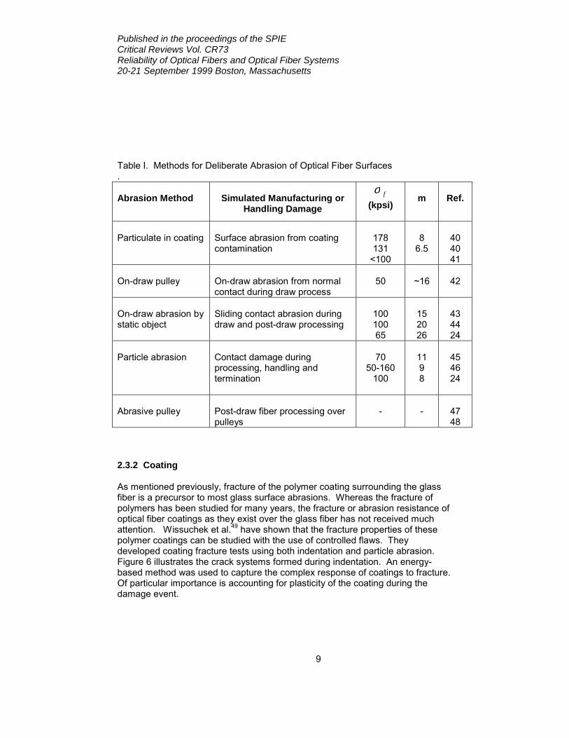
pop-in” is one such behavior. Here the strength of a flaw produced by indentation suddenly drops due to rapid formation of a radial crack from the indentation impression.35,36 The driving force for this flaw formation is localized residual stress formed during the plastic deformation of the glass during indentation. Matthewson3 contends that this phenomenon should be taken more seriously in the modeling of fiber reliability and uses the argument of similarity between indentation flaws and actual flaws in optical fiber. Recently, Ritter et al.29 downplayed the significance of this event by citing silica’s ability to accommodate the indenter or abrasion volume through densification. From a field experience point of view, “pop-in” does not appear so threatening. For over a decade, the author has examined hundreds of post-proof fiber breaks and has never observed a single break that can be attributed to the “pop-in” of flaws as observed with indentation flaws. The vast majority of fiber breaks occur due to excessive stress or damage through the coating.37 The strength and fatigue effects of surface contamination have been studied by deliberately introducing contamination into the draw process. Early work by DiMarcello et al.38 demonstrated dramatic strength decreases by introducing zirconia particulate into the draw furnace environment. Svensson and Breuls39 have attempted to seed fiber preforms with zirconia particles in an attempt to measure the fatigue of fibers with this contaminant. They observed what could best be described as anomalous results with strength actually increasing at slower stressing rates. The difficulty with this type of testing is generating a strength distribution with sufficiently low variability. Flaws produced by mechanical abrasion, usually by particles, have traditionally been used as a type of model flaw. They bring the flaw morphology closer to that of actual flaws than indentation flaws. Mechanical abrasions on optical fiber have been produced using a variety of abrasion methods. In several cases the flaws were created to replicate a particular surface abrasion created during actual manufacturing or handling. Table I summarizes some of these abrasion methods and the manufacturing and handling process they reflect. Strengths near typical proof stress levels can be attained with abrasion flaws. Also, the variety of methods used to produce these flaws covers a wide range of actual fiber handling events. Therefore, the behavior of these flaws should translate well to that of actual flaws. The results from these studies have been shown to be useful in the study of fiber fatigue and process handling on strength. Higher Weibull m values are needed in order to make these flaw types more useful in distinguishing between crack velocity models. To date, model flaws provide qualitative insight into the behavior of actual flaws.3 It is believed that continued comparison between model flaws and actual flaws will narrow the gap between laboratory behavior and industry experience. where Y contains the flaw shape and loading factors and a is the flaw depth. A semi-elliptical surface flaw will have a constant stress intensity factor over the entire crack front when Y = 0.73. 33,34
Published in the proceedings of the SPIE Critical Reviews Vol. CR73 Reliability of Optical Fibers and Optical Fiber Systems 20-21 September 1999 Boston, Massachusetts
9
Table I. Methods for Deliberate Abrasion of Optical Fiber Surfaces . Abrasion Method
Simulated Manufacturing or
Handling Damage fσ
(kpsi)
m
Ref.
Particulate in coating
Surface abrasion from coating contamination
178 131
<100
8
6.5
40 40 41
On-draw pulley
On-draw abrasion from normal contact during draw process
50
~16
42
On-draw abrasion by static object
Sliding contact abrasion during draw and post-draw processing
100 100 65
15 20 26
43 44 24
Particle abrasion
Contact damage during processing, handling and termination
70
50-160 100
11 9 8
45 46 24
Abrasive pulley
Post-draw fiber processing over pulleys
-
-
47 48
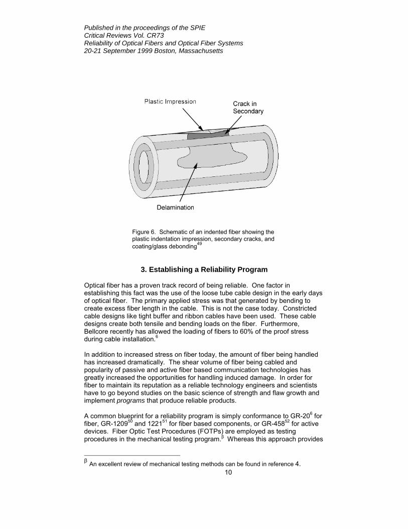
2.3.2 Coating As mentioned previously, fracture of the polymer coating surrounding the glass fiber is a precursor to most glass surface abrasions. Whereas the fracture of polymers has been studied for many years, the fracture or abrasion resistance of optical fiber coatings as they exist over the glass fiber has not received much attention. Wissuchek et al.49 have shown that the fracture properties of these polymer coatings can be studied with the use of controlled flaws. They developed coating fracture tests using both indentation and particle abrasion. Figure 6 illustrates the crack systems formed during indentation. An energy-based method was used to capture the complex response of coatings to fracture. Of particular importance is accounting for plasticity of the coating during the damage event.
Published in the proceedings of the SPIE Critical Reviews Vol. CR73 Reliability of Optical Fibers and Optical Fiber Systems 20-21 September 1999 Boston, Massachusetts
10
Figure 6. Schematic of an indented fiber showing the plastic indentation impression, secondary cracks, and coating/glass debonding49
3. Establishing a Reliability Program Optical fiber has a proven track record of being reliable. One factor in establishing this fact was the use of the loose tube cable design in the early days of optical fiber. The primary applied stress was that generated by bending to create excess fiber length in the cable. This is not the case today. Constricted cable designs like tight buffer and ribbon cables have been used. These cable designs create both tensile and bending loads on the fiber. Furthermore, Bellcore recently has allowed the loading of fibers to 60% of the proof stress during cable installation.6 In addition to increased stress on fiber today, the amount of fiber being handled has increased dramatically. The shear volume of fiber being cabled and popularity of passive and active fiber based communication technologies has greatly increased the opportunities for handling induced damage. In order for fiber to maintain its reputation as a reliable technology engineers and scientists have to go beyond studies on the basic science of strength and flaw growth and implement programs that produce reliable products. A common blueprint for a reliability program is simply conformance to GR-206 for fiber, GR-120950 and 122151 for fiber based components, or GR-45852 for active devices. Fiber Optic Test Procedures (FOTPs) are employed as testing procedures in the mechanical testing program.β Whereas this approach provides
β An excellent review of mechanical testing methods can be found in reference 4.
Published in the proceedings of the SPIE Critical Reviews Vol. CR73 Reliability of Optical Fibers and Optical Fiber Systems 20-21 September 1999 Boston, Massachusetts
11
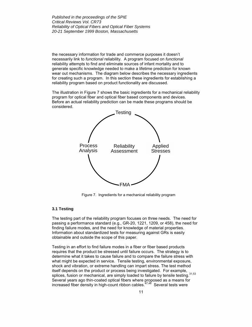
the necessary information for trade and commerce purposes it doesn’t necessarily link to functional reliability. A program focused on functional reliability attempts to find and eliminate sources of infant mortality and to generate specific knowledge needed to make a lifetime prediction for known wear out mechanisms. The diagram below describes the necessary ingredients for creating such a program. In this section these ingredients for establishing a reliability program based on product functionality are discussed. The illustration in Figure 7 shows the basic ingredients for a mechanical reliability program for optical fiber and optical fiber based components and devices. Before an actual reliability prediction can be made these programs should be considered.
Testing
ProcessAnalysis
FMA
AppliedStresses
ReliabilityAssessment
Figure 7. Ingredients for a mechanical reliability program 3.1 Testing The testing part of the reliability program focuses on three needs. The need for passing a performance standard (e.g., GR-20, 1221, 1209, or 458), the need for finding failure modes, and the need for knowledge of material properties. Information about standardized tests for measuring against GRs is easily obtainable and outside the scope of this paper. Testing in an effort to find failure modes in a fiber or fiber based products requires that the product be stressed until failure occurs. The strategy is to determine what it takes to cause failure and to compare the failure stress with what might be expected in service. Tensile testing, environmental exposure, shock and vibration, or extreme handling can impart stress. The test method itself depends on the product or process being investigated. For example, splices, fusion or mechanical, are simply loaded to failure by tensile testing.31,53 Several years ago thin-coated optical fibers where proposed as a means for increased fiber density in high-count ribbon cables.47,48 Several tests were
Published in the proceedings of the SPIE Critical Reviews Vol. CR73 Reliability of Optical Fibers and Optical Fiber Systems 20-21 September 1999 Boston, Massachusetts
12
created in an effort to find failure modes relevant to the processing of thin-coated fibers. Testing for failure modes is more than passing a specified level of performance. It gives a feel for the performance limits of the basic design and should be performed early in the development effort. Processes for manufacturing and handling fiber should be examined for their ability to generate failure modes as well. In most cases fiber-handling equipment is qualified after engineers have carefully tuned the equipment so that it is examined under the best of conditions. However, to test processing equipment for possible failure modes, one would run the equipment at its extremes for speed, alignment, stress, etc. A simple “rule of thumb” is to set these extremes 2X away from the nominal operating condition. Break ends are collected for further examination and the fiber can be rescreened or strength tested in long lengths54 to look for process induced damage. Again, the point here is to push the equipment until something “bad” happens in an effort to determine the limits of the fiber handling process. The testing part of the reliability program also is where one obtains knowledge of material properties and fatigue parameters. Material properties like Young’s modulus, cure shrinkage and glass transition temperature are needed to model environmentally induced in-service stresses. Thermal proof testing can be done provided these material properties are known and incorporated into the applied stress model. Measurements of fatigue behavior have been covered extensively in recent reviews and publications.1,2,3,4,23 Of more recent significance is the need for appropriate crack growth parameters for high speed processing events.7 3.2 Applied Stresses A predictive lifetime model for optical fiber is only as good as the applied stress data or model. Loose tube cable designers have an established set of independent variables for determining the fiber bend configuration and the strain window of the cable. When new cable designs are introduced these variables usually are addressed.55 Loose tube cables usually are considered to be low risk for fiber failures. However, Nagata et al.56 recently examined optical failures in a loose tube cable and concluded that unless the material properties of the loose tube are well characterized the tubes can shrink excessively, thereby placing fibers under excessive bending stresses. Fiber in cable experiences stress even in the most benign of cable designs and analytical models are not always sufficient to ensure tolerable stress levels. Finite element analysis (FEA) has recently been employed to model both cable57 and cabled fiber.58 This type of modeling, though difficult, holds promise for delivering applied stress distributions in complex cable structures. Applied stress measurements for fiber in cable have been around for many years. Time-of-flight and phase-shift methods are used routinely to measure cabled fiber strain (see reference 59 for a recent example). These methods measure the average tensile stresses over a relatively long length of fiber. They should be used when the fiber subjected to the same tensile stress over the entire cable length being measured. Some have found these optical methods
Published in the proceedings of the SPIE Critical Reviews Vol. CR73 Reliability of Optical Fibers and Optical Fiber Systems 20-21 September 1999 Boston, Massachusetts
13
difficult to use and have developed a direct mechanical method for measure tensile strain.60 Fibers in a typical stranded loose-tube cable experience a considerable range of stresses, even over a few centimeters. Similarly, fibers in ribbon cables experience significant tension, compression and bending within a single strand length. In these cases caution must be exercised when using the common optical strain measurement techniques. Brillouin OTDRs can resolve an average stress over several meter fiber lengths,61,62 but this is not sufficient for mechanical reliability assessments of these more complex cable designs. Direct applied stress measurements using in-fiber sensors hold promise for measuring more localized tensile stresses. For example, Bragg gratings written directly into fiber and deployed in a cable or component package would be capable of delivering accurate tensile stress measurements at a discrete location.63 Several gratings strategically placed in a cable would allow for tensile stress mapping. Etched fibers64 also could be used as an embedded strain gauge. What is needed is centimeter length resolution on applied bending and tensile stress measurements for cabled fiber in order to develop a distribution of applied stresses. It is generally assumed that fiber based components and devices have low reliability risk from fiber failure due to the short lengths employed. However, it is common to remove the polymer coating during splicing, connecting and packaging and expose bare glass to handling induced damage.65,66 Once this is done, the earlier proof testing performed during fiber manufacturing no longer has relevance. Furthermore, fibers can experience tight bends to accommodate the package design.67-70 It is these situations that pose the greatest reliability risk for fiber components and devices. More research is not the answer here. Rather, knowledge and control over applied stresses coupled with strength testing or proof testing and a set of generally accepted best practices for handling fiber are needed. For coated fiber, the long-term applied stress should be no greater than 1/5th the proof stress unless one performs an extensive investigation into the probability of encountering a proof stress level flaw.15,71 Fiber stripped of its coating should be proof tested to five times the applied stress and protected from further damage. 3.3 Failure Mode Analysis (FMA) Failure mode analysis is simply the task of determining the cause of failure and is a crucial step in analyzing test results as well as early failures during processing. The analysis of the fiber breaks traditionally is called Break Source Analysis (BSA). Skilled persons are able to read coating and glass fracture surface features to determine the cause of failure.72,73 The primary tool is an optical microscope. Scanning Electron Microscopy (SEM) is of value in determining the composition of contaminants. Atomic Force Microscopy (AFM) is a proven research tool74,75 and has found some use in FMA or BSA investigations.
Published in the proceedings of the SPIE Critical Reviews Vol. CR73 Reliability of Optical Fibers and Optical Fiber Systems 20-21 September 1999 Boston, Massachusetts
14
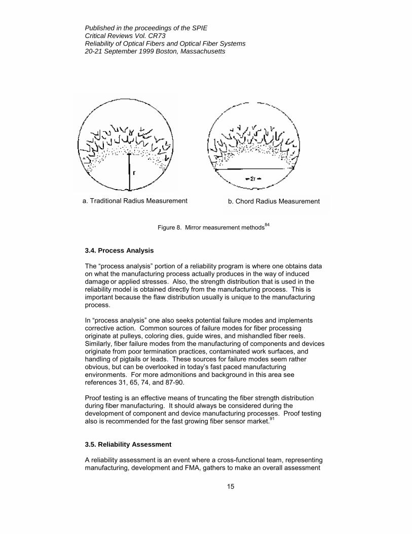
Optical fiber has been deployed for over two decades and retrieval of fibers, components and devices from the field provides an important feedback loop into failure modes of fiber based technologies. Several FMA studies on early fibers showed evidence of strength degradation. Fibers exposed to steam explosions76 or left unprotected in the cable yard77 experienced strength degradation. Some early fibers designed to have low mechanical adhesion were found to be difficult to handle after prolonged exposure to wet conditions.78 It also was found that one must take care to avoid coating damage while removing fibers from a cable, since such damage can make it difficult to interpret the post-aging strength distribution. Several studies on field aged fibers have been conducted on more modern fiber types79-82 and in each case no strength degradation or handleability issues were observed. It is important to continue this form of examination as the fiber network ages. In 1993 Lisle37 published an extensive review of failure modes for deployed cable. To no one’s surprise, “dig-ups” were the largest source of premature failure. One can find an excellent review of field failure modes for components that make up DWDM transmission systems in reference 83. One of most important requirements for performing FMA or BSA is having the failed component or fiber as close to the as-failed state as possible. For example, a fiber break in a buffer tube is best left in the tube until the fractologist begins the dissection. Similarly, a break in a component package should be left undisturbed. The position of the fiber and the surrounding materials are extremely important. Many times the fiber coating is removed before the fractologist begins the BSA, but more than half of the failure history is found in the coating. Mechanically stripping the coating during the dissection introduces more flaws and can mask the original cause of failure. Sometimes only a few centimeters of fiber are provided or the break ends are covered with tape. Great care is needed in preparing for FMA and BSA. A common method for determining tensile failure stress from fiber fracture surface features is to obtain the mirror radius by measuring radially across the fiber as shown in Figure 8a. This method avoids the effects of surface features that can disturb the mirror region near the glass surface.84 However, the more common method for measuring fracture mirrors for glass in general is the chord method shown in Figure 8b.85 The chord method has less influence from bending induced stresses which elongate the mirror in the radial direction and result in an underestimation of the applied stress at failure. Furthermore, since the fiber surface is usually unblemished away from the actual damage site, the mirror region near the surface is less apt to be altered by surface effects. Baker and Glaesemann86 reaffirmed this in their recent comparison of the two methods.
Published in the proceedings of the SPIE Critical Reviews Vol. CR73 Reliability of Optical Fibers and Optical Fiber Systems 20-21 September 1999 Boston, Massachusetts
15
Figure 8. Mirror measurement methods84 3.4. Process Analysis The “process analysis” portion of a reliability program is where one obtains data on what the manufacturing process actually produces in the way of induced damage or applied stresses. Also, the strength distribution that is used in the reliability model is obtained directly from the manufacturing process. This is important because the flaw distribution usually is unique to the manufacturing process. In “process analysis” one also seeks potential failure modes and implements corrective action. Common sources of failure modes for fiber processing originate at pulleys, coloring dies, guide wires, and mishandled fiber reels. Similarly, fiber failure modes from the manufacturing of components and devices originate from poor termination practices, contaminated work surfaces, and handling of pigtails or leads. These sources for failure modes seem rather obvious, but can be overlooked in today’s fast paced manufacturing environments. For more admonitions and background in this area see references 31, 65, 74, and 87-90. Proof testing is an effective means of truncating the fiber strength distribution during fiber manufacturing. It should always be considered during the development of component and device manufacturing processes. Proof testing also is recommended for the fast growing fiber sensor market.91 3.5. Reliability Assessment A reliability assessment is an event where a cross-functional team, representing manufacturing, development and FMA, gathers to make an overall assessment
a. Traditional Radius Measurement b. Chord Radius Measurement
Published in the proceedings of the SPIE Critical Reviews Vol. CR73 Reliability of Optical Fibers and Optical Fiber Systems 20-21 September 1999 Boston, Massachusetts
16
of the reliability of the fiber based product. The assessment covers two basic areas related to mechanical reliability; namely, infant or early failures and wear out failures. Early failures are eliminated by careful examination of every fiber handling event and the results of the testing program. The probability of failure from wear out mechanisms like fatigue is assessed by inputting applied stresses, strength distributions and fatigue parameters into the reliability model. For long-length applications, the allowable stress should be based on a percentage of the proof stress. This is called a “minimum strength” design. Basically, one treats the fiber as being no stronger than the proof stress level. A search of reliability models reveals applied stress to proof stress ratios of 1/3rd to 1/6th. As stated earlier, the author recommends the 1/5th rule for 20 to 40 year terrestrial applications. This methodology also should be used in fiber termination as well. That is to say, anytime the coating is removed the fiber should be reproof-tested and the minimum strength design employed. The applied stress design rule for submarine applications usually is more conservative than that for terrestrial applications due to the greater consequences for an undersea fiber failure. A failure probability model can be used provided the strength distribution is representative of the in-service application. For example, long-length applications require strength distributions consisting of many kilometers of data.92 Some reliability models use the fiber break rate during proof testing as a means for incorporating the strength distribution into the failure probability prediction.93 Paul and Glaesemann94 questioned the underlying assumption for this model that the flaws failing proof testing come from the same distribution as those that survive. That is to say, the distribution of flaws that pass proof testing, and are placed in service, cannot be predicted from those that fail proof testing. They performed extensive testing and found little correlation between proof test break rate and the post proof strength distribution. Coated fiber pigtails are excellent candidates for a failure probability design since the probability of finding a proof stress level flaw is low. It still is important to have a long-length strength distribution even for these applications. In the case where regions of the fiber are exposed to different stresses or the strength distribution varies, one divides the product into regions for reliability assessment. The reliability of each region then is determined and the total reliability for the entire product is obtained by simply multiplying the reliability’s of all regions,8
i
n
iT RR1=
Π= (2)
This equation is for regions in series, which usually is the case for fiber applications. One can clearly see that the region with the lowest reliability governs the reliability of the total product. An example of such a reliability assessment for wear out failures can be found in reference 70.
Published in the proceedings of the SPIE Critical Reviews Vol. CR73 Reliability of Optical Fibers and Optical Fiber Systems 20-21 September 1999 Boston, Massachusetts
17
4. Summary This article reviewed some of the recent research on the mechanical behavior of flaws in optical fiber. High speed testing of proof test level flaws enables more accurate modeling of high speed processing events. Although there appears to be a correlation between fictive temperature and fatigue behavior the proposed theory does not explain differences in fatigue behavior between large flaws in bulk glass and small flaws in optical fiber. Surrogate flaws continue to be used for modeling the mechanical behavior of as-manufactured flaws in optical fiber. Indentation flaws are simpler than those produced by mechanical abrasion; however, abrasion induced flaws better represent actual as-manufactured flaws. New research into the fracture behavior of protective polymer coatings was reviewed. This is a first step toward a more comprehensive fracture mechanics model for abrasion resistance. The key ingredients for a successful mechanical reliability program were presented. It is recommended that the testing part of the program go beyond simply testing to a standard. Rather one attempts to seek failure modes by testing the limits of the product or process. Applied stresses are just as important as strength and fatigue information. Finite Element Analysis is beginning to be used to model complex cable structures. Increased spatial resolution is needed for measuring applied stresses for cabled fiber. Failure Mode Analysis (FMA) and Break Source Analysis (BSA) are the tools one employs to discover the cause of fiber failure. A good optical microscope is needed as well as a user who is experienced in fractography. The process analysis step is where one learns what the process generates by way of induced damage and applied stresses. Recommendations for minimizing early failures were given for both fiber processing and fiber handling. Proof testing remains an effective tool in controlling the strength distribution. The actual reliability assessment consists of an in depth review of modes for early failures and predictions for wear out failures.
References 1. C.R. Kurkjian, J.T. Krause, and M.J. Matthewson, “Strength and Fatigue of
Silica Optical Fibers,” J. Lightwave Tech. 7 [9] 1360-1370 (1989). 2. C.R. Kurkjian, P.G. Simpkins, and D. Inniss, “Strength, Degradation, and
Coating of Silica Lightguides,” J. Am. Ceram. Soc. 76 [5] 1106-1112 (1993). 3. M.J. Matthewson, “Optical Fiber Reliability Models,” Fiber Optics Reliability
and Testing, Edited by D.K. Paul, CR50, 3-31, Proceedings of the SPIE, Bellingham, WA, 1993.
4. M.J. Matthewson, “Optical Fiber Mechanical Testing Techniques,” Fiber Optics Reliability and Testing, Edited by D.K. Paul, CR50, 32-59, Proceedings of the SPIE, Bellingham, WA, 1993.
5. C.R. Kurkjian, “Critical Issues in the Mechanical Reliability of Lightguide Fibers,” Reliability of Photonics Materials and Structures, Edited by E. Suhir,
Published in the proceedings of the SPIE Critical Reviews Vol. CR73 Reliability of Optical Fibers and Optical Fiber Systems 20-21 September 1999 Boston, Massachusetts
18
M. Fukuda, and C.R. Kurkjian, 531, 39-44, Proceedings of the Materials Research Society, San Francisco, 1998.
6. Bellcore GR-20-CORE, Issue 2, July 1998. 7. G.S. Glaesemann, D.A. Clark, T.A. Hanson, and D.J. Wissuchek, “High-
Speed Strength Testing of Optical Fiber,” Reliability of Photonics Materials and Structures, Edited by E. Suhir, M. Fukuda, and C.R. Kurkjian, 531, 249-260, Proceedings of the Materials Research Society, San Francisco, 1998.
8. D. Kececioglu, Reliability Engineering Handbook volume 1, Prentice-Hall, Upper Saddle River, NJ, 1991.
9. M.J. Matthewson, “Chemical Kinetics Models for the Fatigue Behavior of Fused Silica Optical Fibers,” Reliability of Photonics Materials and Structures, Edited by E. Suhir, M. Fukuda, and C.R. Kurkjian, 531, 143-153, Proceedings of the Materials Research Society, San Francisco, 1998.
10. S.L. Semjonov, G.S. Glaesemann, C.R. Kurkjian, and M.M. Bubnov, “Modeling of Proof Test Level Flaws Using Cube Corner Indents,” Proceedings of the 47th International Wire and Cable Symposium, 928-932, Philadelphia, PA, 1998.
11. P.T. Garvey, T.A. Hanson, M.G. Estep, G.S. Glaesemann, “Mechanical Reliability Predictions: An Attempt at Measuring the Initial Strength of Draw-Abraded Optical Fiber Using High Stressing Rates,” Proceedings of the 46th International Wire and Cable Symposium, 883-887, Philadelphia, PA, 1997.
12. T. Svensson, “Evaluation of B-Values of Telecom Fibers, Objectives and Methods,” Reliability of Photonics Materials and Structures, Edited by E. Suhir, M. Fukuda, and C.R. Kurkjian, 531, 47-52, Proceedings of the Materials Research Society, San Francisco, 1998.
13. A. Gouronnec and N. Evanno, “High Speed Axial Strength Setup for the Measurement of the “B” Value,” Proceedings of the 45th International Wire and Cable Symposium, 906-913, Reno, NV, 1996.
14. T. Volotinen, A. Breuls, N. Evanno, K. Kemeter, C. Kurkjian, P. Regio, S. Semjonov, T. Svensson, and G.S. Glaesemann, “Mechanical Behavior and B-Value of an Abraded Optical Fiber,” Proceedings of the 47th International Wire and Cable Symposium, 881-890, Philadelphia, PA, 1998.
15. T.A. Hanson and G.S. Glaesemann, “Incorporating Multi-Region Crack Growth into Mechanical Reliability Predictions for Optical Fibers,” J. Mat. Sci., 32, 5305 – 5311 (1997).
16. H.C. Chandan, R.C. Bradt, and G.E. Rindone, “Dynamic Fatigue of Float Glass,” J. Am. Ceram. Soc. 61 [5-6] 207-210 (1978).
17. M. Muraoka, K. Ebata, and H. Abe, “Effect of Humidity on Small-Crack Growth in silica Optical Fibers,” J. Am. Ceram. Soc. 76 [6] 1545-1550 (1993).
18. H. Li, A. Agarwal, and M. Tomozawa, “Effect of Temperature on Dynamic Fatigue of Silica and Soda-Lime Glasses,” J. Am. Ceram. Soc. 78 [5] 1393-1396 (1995).
19. Y.L. Peng, A. Agarwal, M. Tomozawa, and T.A. Blanchet, “Radial Distribution of Fictive Temperatures in Silica Optical Fibers,” J. Non-Cryst. Solids 217, 272-277 (1997)
20. B. Varughese, Y.-K. Lee, and M. Tomozawa, “Effect of Fictive Temperature on Mechanical Strength of Soda-Lime Glass,” J. Non-Cryst. Solids 241, 134-139 (1998).
21. T. Volotinen, M. Zimnol, M. Tomozawa, Y.-K. Lee, and K. Raine, “Effect of Mechanical Stripping and Arc-Fusion on the Strength and Aging of a Spliced
Published in the proceedings of the SPIE Critical Reviews Vol. CR73 Reliability of Optical Fibers and Optical Fiber Systems 20-21 September 1999 Boston, Massachusetts
19
Recoated Optical Fiber,” Reliability of Photonics Materials and Structures, Edited by E. Suhir, M. Fukuda, and C.R. Kurkjian, 531, 163-168, Proceedings of the Materials Research Society, San Francisco, 1998.
22. T.A. Michalske, W.L. Smith, and B.C. Bunker, “Fatigue Mechanisms in High-Strength Silica-Glass Fibers,” J. Am. Ceram. Soc. 74 [8] 1993-1996 (1991).
23. G.S. Glaesemann, “The Mechanical Behavior of Large Flaws in Optical Fiber and Their Role in Reliability Predictions,” Proceedings of the 41st International Wire and Cable Symposium, 689-704, Reno, NV, 1992.
24. D.B. Marshall and B.R. Lawn, “Flaw Characteristics in Dynamic Fatigue: The Influence of Residual Contact Stresses,” J. Am. Ceram. Soc. 63 [9-10] 532-536 (1980).
25. M. A. Isreal, J.E. Ritter, Jr., K. Jakus, “Strength and Dynamic Fatigue Behavior of Indented Borosilicate and Soda-Lime Glasses,” Physics Chem. Glasses 28 [4] 133-138 (1987).
26. R.D. Maurer, “Behavior of Flaws in Fused Silica Fibers,” Strength of Inorganic Glass, Edited by C.R. Kurkjian, 291-308, Plenum Press, New York, 1985.
27. D.G Holloway, “The Fracture Behavior of Glass,” Glass Tech. 27 [4] 120-133 (1986).
28. S.M. Wiederhorn and B.R. Lawn, “Strength Degradation of Glass Impacted with Sharp Particles: I, Annealed Surfaces,” J. Am. Ceram. Soc., 62 [1-2] 66-74 (1979).
29. J.E. Ritter, K. Jakus, and R.P. Panat, “Impact Damage and Strength Degradation of Fused Silica,” Reliability of Photonics Materials and Structures, Edited by E. Suhir, M. Fukuda, and C.R. Kurkjian, 531, 53-58, Proceedings of the Materials Research Society, San Francisco, 1998.
30. K. Yoshida, T. Satoh, N. Enomoto, T. Yagi, H. Hihara, and M. Oku, “Fracture Origins of Optical Fibers Fabricated by Hybridized Process,” J. Lightwave Tech. 14 [11] 2506-12 (1996).
31. J.T. Krause, “Factors Affecting Arc Fusion Splice Strengths,” SPIE 2611, 98-109 (1994).
32. D.J. Wissuchek, “Effect of Refractory Particles on the Strength of Optical Fibers,” Reliability of Photonics Materials and Structures, Edited by E. Suhir, M. Fukuda, and C.R. Kurkjian, 531, 187-192, Proceedings of the Materials Research Society, San Francisco, 1998.
33. J.C. Newman and I.S. Raju, “An Empirical Stress Intensity Factor Equation for the Surface Crack,” Eng. Fract. Mech. 15 [1-2] 185-192 (1981).
34. G.S. Glaesemann, K. Jakus, and J.E. Ritter, Jr., “Strength Variability of Indented Soda-Lime Glass,” J. Am. Ceram. Soc. 70 [6] 441-444 (1987).
35. T.P. Dabbs and B.R. Lawn, “Strength and Fatigue Properties of Optical Glass Fibers Containing Micro-Indentation Flaws,” J. Am. Ceram. Soc. 68 563-569 (1985).
36. M.J. Matthewson, B. Lin, and A.P. Stanzeski, “Modeling of Weak Optical Fiber by Using Vickers Indentation,” OFC’94 Tech. Digest, 5 245-246 (1994).
37. S.V. Lisle, “The History, Prevention, and Impact of Fiber Cable Failures,”, Proceedings of the National Fiber Optic Engineers Conference, 223-235, NFOEC, San Antonio, TX, 1993.
38. F.V. DiMarcello, A.C. Hart, Jr., J.C. Williams, and C.R. Kurkjian, “High Strength Furnace-Drawn Optical Fibers,” Fiber Opt., 125-135 (1979).
Published in the proceedings of the SPIE Critical Reviews Vol. CR73 Reliability of Optical Fibers and Optical Fiber Systems 20-21 September 1999 Boston, Massachusetts
20
39. T. Svensson and A. Breuls, “Strength and Fatigue of Different Kind of Weak Spots from the Manufacture of Optical Glass Fibres,” SPIE 2290, 211-219 (1994).
40. F.A. Donaghy and D.R. Nicol, “Evaluation of the Fatigue Constant n in Optical Fibers with Surface Particle Damage,” J. Am. Ceram. Soc. 66 [8] 601-604 (1983).
41. R.G. Huff and F.V. DiMarcello, “Critical Particle Size of Contaminants in High and Low Modulus Coatings for High-Strength Optical Lightguides,” J. Lightwave Tech. 3 [5] 950-953 (1985).
42. S. Sakaguchi and Y. Hibino, “Fatigue in Low-Strength Silica Optical Fibres,” J. Mat. Sci. 19, 3416-3420 (1984).
43. S.T. Gulati, J.D. Helfinstine, B. Justice, J.S. McCartney, and M.A. Runyan, “Measurement of Stress Corrosion Constant n for Optical Fibers,” J. Am. Ceram. Soc. Bull. 58 [11] 1115-1117 (1979).
44. K. Abe and R. Ernst, “Static and Dynamic Fatigue Tests of Abraded Optical Fibre,” Elec. Lett. 21 [20] 926-928 (1985).
45. S.P. Craig, W.J. Duncan, P.W. France, and J.E. Snodgrass, “The Strength and Fatigue of Large Flaws in Silica Optical Fibres,” Proceedings of the 8th ECOC, Cannes, France, 1982.
46. H.H. Yuce, P.L. Key, and D.R. Biswas, “Investigation of the Mechanical Behavior of Low Strength Fibers,” Fiber Optics Reliability: Benign and Adverse Environments III, SPIE 1174, 272-278 (1989).
47. K. Oishi, W. Katsurashima, T. Kakuta, Y. Matsuda, and S. Tanaka, “Coating Design of Thin Coated Fiber for Ultra-High-Count Optical Fiber Cable,” Proceedings of the 42nd International Wire and Cable Symposium, 687-693, St. Louis, MO, 1993.
48. G.S. Glaesemann, “Process Handleability of Thin-Coated Optical Fibers," OFC’94 Tech. Digest, 5 243-244 (1994).
49. D.J. Wissuchek, D.J. Walter, D.A. Clark, and G.S. Glaesemann, “Fracture and Abrasion Resistance Tests for Optical Fiber Coatings,” Reliability of Photonics Materials and Structures, Edited by E. Suhir, M. Fukuda, and C.R. Kurkjian, 531, 309-314, Proceedings of the Materials Research Society, San Francisco, 1998.
50. Bellcore GR-1209-CORE, Issue 2, February 1998 51. Bellcore GR-1221-CORE, Issue 2, January 1999. 52. Bellcore GR-468-CORE, Issue 1, December 1998. 53. A. Dwivedi and J.L. Smith, “Characterizing Field Handleability of Optical
Fiber through the Measurement of Strength after Mechanical Stripping,” Proceedings of the 45th International Wire and Cable Symposium, 381-390, Philadelphia, PA, 1996.
54. G.S. Glaesemann and D.J. Walter, “Method for Obtaining Long-Length Strength Distributions for Reliability Prediction,” Opt. Eng. 30 [6] 746-748 (1991).
55. For example, see J. Horska, “Design of Loose Tube Fiber Optic Cable with Adjusted Contraction and Strain Windows,” Proceedings of the 43rd International Wire and Cable Symposium, 50-58, Atlanta, GA, 1997.
56. H. Nagata, K. Ooto, M. Shiroishi, and J. Ogiwara, “Failure Case Study for Loose Tube Jacketed Optical Fibers,” Opt. Fiber Tech. 4, 480-489 (1998).
Published in the proceedings of the SPIE Critical Reviews Vol. CR73 Reliability of Optical Fibers and Optical Fiber Systems 20-21 September 1999 Boston, Massachusetts
21
57. J. B. Stevens, P. Elission, B. Risch, and C. Bastide, “Finite Element Modeling of Optic Fiber Cable Crush Performance,” Proceedings of the 47th International Wire and Cable Symposium, 25-33, Philadelphia, PA, 1998.
58. E. Opel, A. Stingl, M. Schuebbe, “Bending Simulation of a Slotted Core Cable,” Proceedings of the 46th International Wire and Cable Symposium, 810-818, Philadelphia, PA, 1997.
59. A. Makiyama, J. Ohta, and A. Nishimura, “A Study on Strain Characteristics of Fiber Ribbons in a SZ-Grooved Spacer caused by Cable Bending,” Proceedings of the 47th International Wire and Cable Symposium, 216-219, Philadelphia, PA, 1998.
60. C.S. Ma, L.L. Blyler, G.E. Johnson, R.T. Traut, C.E. Murphy, M.W. Jones, F.C. Gibson, W.M. Keith, “Direct Mechanical Fiber Strain Measurement and the Cabled Fiber Strain of an Undersea Cable,” Proceedings of the 47th International Wire and Cable Symposium, 241-248, Atlanta, GA, 1994.
61. C.J. Sandwith, W.D. McCormick, J.A. Thornton, D.R. Wise, R.I. Odom, “Fiber-Strain Measurement using Brillouin Optical-Fiber Time-Domain Analysis,” Proceedings of the 45th International Wire and Cable Symposium, 415-427, Philadelphia, PA, 1996.
62. T. Horiguchi, T. Kurashima, M. Tateda, K. Ishihara, and Y. Wakui, “Brillouin Characterization of Fiber Strain in Bent Slot-Type Optical-Fiber Cables,” J. Lightwave Tech. 10 [9] 1196-1201 (1992). and N. Okada, K. Watanabe, M. Miyanoto, “Strain Analysis of U-Groove Type Cable with Multi Fiber Ribbons,” Proceedings of the 43rd International Wire and Cable Symposium, 211-218, Atlanta, GA, 1994.
63. G. Meltz, J.R. Dunphy, W.H. Glenn, J.D. Farina, and F.J. Leonberger, “Fiber Optic Temperature and Strain Sensors,” Fiber Optic Sensors SPIE 798 104-111 (1987).
64. M. Vaziri and C.-L. Chen, “Etched Fibers as Strain Gauges,” J. Lightwave Tech. 10 [6] 836-841 (1992).
65. W.R. Wagner, “Failure Analysis of Fiber Optic Connectors,” Advances in Ceramics, Volume 22, Fractography of Glasses and Ceramics, 389-402, American Ceramic Society (1988).
66. T. Wei, H.H. Yuce, C.H. Hasz, and P.L. Key, “Degradation of Fiber Strength during Coating Stripping,” Proceedings of the 38th International Wire and Cable Symposium, 199-203, Atlanta, GA, 1989.
67. E. Suhir, “Bending Stress in an Optical Fiber Interconnect Experiencing Significant Ends Off-Set,” Reliability of Photonics Materials and Structures, Edited by E. Suhir, M. Fukuda, and C.R. Kurkjian, 531, 209-214, Proceedings of the Materials Research Society, San Francisco, 1998.
68. E. Suhir, “ Bending of an Optical Glass Fiber ‘Pigtail’ in a Splice Box Structure,” Reliability of Photonics Materials and Structures, Edited by E. Suhir, M. Fukuda, and C.R. Kurkjian, 531, 215-222, Proceedings of the Materials Research Society, San Francisco, 1998.
69. J.M. Anderson, J.F. Malluck, M.M. Tabaddor, C.K. Sidbury, and T.E. McNeil, “Optical-Fiber and Entry-Cone Contact Stress,” Reliability of Photonics Materials and Structures, Edited by E. Suhir, M. Fukuda, and C.R. Kurkjian, 531, 223-229, Proceedings of the Materials Research Society, San Francisco, 1998.
70. L.K. Baker and G.S. Glaesemann, "A Mechanical Reliability Study Of Bare Fibers Under Stress," to be presented at the International Institute for
Published in the proceedings of the SPIE Critical Reviews Vol. CR73 Reliability of Optical Fibers and Optical Fiber Systems 20-21 September 1999 Boston, Massachusetts
22
Connector and Interconnection technology symposium in Anaheim, CA, September 1999.
71. G.S. Glaesemann, “Design Methodology for the Mechanical Reliability of Optical fiber,” Opt. Eng. 30 [6] 709-715 (1991).
72. V.D. Frechette, Advances in Ceramics: Failure Analysis of Brittle Materials, 28, American Ceramic Society, Westerville, OH, 1990.
73. J.J. Mecholsky, “Fracture Surface Analysis of Optical Fibers,” Ceramics and Glasses, Engineered Materials Handbook, 4, edited by S.J. Schneider, Jr., 663-668 ASM 1991.
74. J.D. Mann, O.S. Gebizlioglu, and C.R. Kurkjian, “The Effect of Preparation Conditions on the Strength of Fusion Splices I: Use of AFM Imaging,” Proceedings of the 47th International Wire and Cable Symposium, 589-596, Philadelphia, PA, 1998.
75. Q. Zhong, D. Inniss, K. Kjoller, and V.B. Elings, “Fractured Polymer/Silica Fiber Surface Studied by Tapping Mode Atomic Force Microscopy,” Surface Sci. Letts. 290 1688-1692 (1993).
76. H.H. Yuce, T. Wei, R. Estes, C.J. Wieczorek, B.T. Devlin, J.P. Kilmer, and J.P. Varachi, Jr., “Fiber Reliability Study of Field Aged Optical Cables,” Proceedings of the 41st International Wire and Cable Symposium, 705-712, Reno, NE, 1992.
77. H.H. Yuce, C.J. Weiczorek, A. DeVito, J.P. Varachi, Jr., and J.P. Kilmer, “Effects of the Environment on an Unprotected Reel of Optical Fiber Cable,” Proceedings of the 40th International Wire and Cable Symposium, 700-705, St. Louis, MO, 1991.
78. W. Griffioen, T. Volotinen, P. Wilson, A. Gouronnec, T. Svensson, “Handleability of Aged Optical Fibers,” Proceedings of the 44th International Wire and Cable Symposium, 857-864, Philadelphia, PA, 1995.
79. A. Dwivedi, G.S. Glaesemann, and C.K. Eoll, “Optical Fiber Strength, Fatigue and Handleability after Aging in a Cable,” Proceedings of the 43rd International Wire and Cable Symposium, 728-735, Atlanta, GA, 1994.
80. J.L. Smith, A. Dwivedi, and P.T. Garvey, “Mechanical Behavior of Optical Fibers Removed from a Field-Aged Cable,” Proceedings of the 44th International Wire and Cable Symposium, 848-856, Philadelphia, PA, 1995.
81. M.L. Lundergan, B.D. Zimmerman, B. Waterman, “Mechanical and Optical Functionality of Field-Aged Optical Ground Wire Cable,” Proceedings of the National Fiber Optic Engineers Conference, 449-458, NFOEC, 1996.
82. K. Houser and S. Chahanovich, “Verification of Optical Fiber and Cable Reliability,” Proceedings of the 47th International Wire and Cable Symposium, 468-474, Philadelphia, PA, 1998.
83. S. Etemad, “Dense-WDM Components and Systems: A Reliability Overview,” Reliability of Photonics Materials and Structures, Edited by E. Suhir, M. Fukuda, and C.R. Kurkjian, 531, 27-38, Proceedings of the Materials Research Society, San Francisco, 1998.
84. E.B. Shand, “Breaking Stress of Glass Determined from Dimensions of Fracture Mirrors,” J. Am. Ceram. Soc. 42 [10] 474-477 (1959).
85. J.J. Mecholsky, R.W. Rice and S.W. Freiman, “Prediction of Fracture Energy and Flaw Size in Glasses from Measurements of Mirror Size,” J. Am. Ceram. Soc. 57 [10] 440-443 (1974).
Published in the proceedings of the SPIE Critical Reviews Vol. CR73 Reliability of Optical Fibers and Optical Fiber Systems 20-21 September 1999 Boston, Massachusetts
23
86. L.K. Baker and G.S. Glaesemann, “Break Source Analysis: Alternative Mirror Measurement Method,” Proceedings of the 46th International Wire and Cable Symposium, 933-937, Philadelphia, PA, 1997.
87. G. Kiss and E. Vogel, “High Yield Fusion Splicing In The Outside Plant: Using Fiber Meltback To Monitor Electrode Condition” Proceedings of the National Fiber Optic Engineers Conference, 819-835, NFOEC, 1996.
88. J.T. Krause, “Ultrahigh-Strength Fibre Splices by Modified H2/O2 Flame Fusion,” Elec. Letters 22 [20] 1075-1077 (1986).
89. G. Kiss, “Reliability of Optical Splices,” Fiber Optics Reliability and Testing, Edited by D.K. Paul, CR50, 118-154, Proceedings of the SPIE, Bellingham, WA, 1993.
90. W.W. King, B.G. LeFevre, and D.L. Stephenson, “Structural Mechanics Aspects of Fractures of Optical Fibers in Connectors,” Proceedings of the 46th International Wire and Cable Symposium, 228-235, Reno, NV, 1996.
91. M. Komachiya, R. Minamitani, T. Fumino, T. Sakaguchi, and S. Watanabe, “Proof-Testing and Probabilistic Lifetime Estimation of Glass Fibers for Sensor Applications,” Appl. Optics 38 [13] 2767-2774 (1999).
92. G.S. Glaesemann, “Optical Fiber Failure Probability Predictions from Long-Length Strength Distributions,” Proceedings of the 40th International Wire and Cable Symposium, 819-825, St. Louis, MO, 1991.
93. Y. Mitsunaga, Y. Katsuyama, H. Kobayashi, and Y Ishida, “Failure Prediction for Long-Length Optical Fiber Based on Proof Testing,” J. Appl. Phys. 53 [7] 4847-4853 (1982).
94. A. Paul and G.S. Glaesemann, “An Appraisal of Mechanical Reliability Predictions for Optical Fibers Based on Break Rates,” Proceedings of the 46th International Wire and Cable Symposium, 896-901, Philadelphia, PA, 1997.