ADVANCED TECHNOLOGIES FOR EFFICIENT TRANSPORTATION ...
56
University of Kentucky University of Kentucky UKnowledge UKnowledge Theses and Dissertations--Civil Engineering Civil Engineering 2018 ADVANCED TECHNOLOGIES FOR EFFICIENT TRANSPORTATION ADVANCED TECHNOLOGIES FOR EFFICIENT TRANSPORTATION CONSTRUCTION INSPECTION CONSTRUCTION INSPECTION Clyde Wesley Newcomer IV University of Kentucky, [email protected] Digital Object Identifier: https://doi.org/10.13023/ETD.2018.141 Right click to open a feedback form in a new tab to let us know how this document benefits you. Right click to open a feedback form in a new tab to let us know how this document benefits you. Recommended Citation Recommended Citation Newcomer, Clyde Wesley IV, "ADVANCED TECHNOLOGIES FOR EFFICIENT TRANSPORTATION CONSTRUCTION INSPECTION" (2018). Theses and Dissertations--Civil Engineering. 67. https://uknowledge.uky.edu/ce_etds/67 This Master's Thesis is brought to you for free and open access by the Civil Engineering at UKnowledge. It has been accepted for inclusion in Theses and Dissertations--Civil Engineering by an authorized administrator of UKnowledge. For more information, please contact [email protected].
Transcript of ADVANCED TECHNOLOGIES FOR EFFICIENT TRANSPORTATION ...
University of Kentucky University of Kentucky
UKnowledge UKnowledge
Theses and Dissertations--Civil Engineering Civil Engineering
2018
ADVANCED TECHNOLOGIES FOR EFFICIENT TRANSPORTATION ADVANCED TECHNOLOGIES FOR EFFICIENT TRANSPORTATION
CONSTRUCTION INSPECTION CONSTRUCTION INSPECTION
Clyde Wesley Newcomer IV University of Kentucky, [email protected] Digital Object Identifier: https://doi.org/10.13023/ETD.2018.141
Right click to open a feedback form in a new tab to let us know how this document benefits you. Right click to open a feedback form in a new tab to let us know how this document benefits you.
Recommended Citation Recommended Citation Newcomer, Clyde Wesley IV, "ADVANCED TECHNOLOGIES FOR EFFICIENT TRANSPORTATION CONSTRUCTION INSPECTION" (2018). Theses and Dissertations--Civil Engineering. 67. https://uknowledge.uky.edu/ce_etds/67
This Master's Thesis is brought to you for free and open access by the Civil Engineering at UKnowledge. It has been accepted for inclusion in Theses and Dissertations--Civil Engineering by an authorized administrator of UKnowledge. For more information, please contact [email protected].

STUDENT AGREEMENT: STUDENT AGREEMENT:
I represent that my thesis or dissertation and abstract are my original work. Proper attribution
has been given to all outside sources. I understand that I am solely responsible for obtaining
any needed copyright permissions. I have obtained needed written permission statement(s)
from the owner(s) of each third-party copyrighted matter to be included in my work, allowing
electronic distribution (if such use is not permitted by the fair use doctrine) which will be
submitted to UKnowledge as Additional File.
I hereby grant to The University of Kentucky and its agents the irrevocable, non-exclusive, and
royalty-free license to archive and make accessible my work in whole or in part in all forms of
media, now or hereafter known. I agree that the document mentioned above may be made
available immediately for worldwide access unless an embargo applies.
I retain all other ownership rights to the copyright of my work. I also retain the right to use in
future works (such as articles or books) all or part of my work. I understand that I am free to
register the copyright to my work.
REVIEW, APPROVAL AND ACCEPTANCE REVIEW, APPROVAL AND ACCEPTANCE
The document mentioned above has been reviewed and accepted by the student’s advisor, on
behalf of the advisory committee, and by the Director of Graduate Studies (DGS), on behalf of
the program; we verify that this is the final, approved version of the student’s thesis including all
changes required by the advisory committee. The undersigned agree to abide by the statements
above.
Clyde Wesley Newcomer IV, Student
Dr. Gabriel Dadi, Major Professor
Dr. Y. T. Wang, Director of Graduate Studies
ADVANCED TECHNOLOGIES FOR EFFICIENT TRANSPORTATION CONSTRUCTION
INSPECTION
THESIS
A thesis submitted in partial fulfillment of the requirements for
the degree of Master of Science in Civil Engineering in the
College of Engineering at the University of Kentucky
By
Clyde Wesley Newcomer IV
Lexington, Kentucky
Director: Dr. Gabriel Dadi, Department of Civil Engineering, University of Kentucky
Lexington, Kentucky
2018
Copyright© Clyde Wesley Newcomer IV 2018

ABSTRACT OF THESIS
ADVANCED TECHNOLOGIES FOR EFFICIENT TRANSPORTATION CONSTRUCTION
INSPECTION
Collecting load tickets is an example of an antiquated practice that puts inspectors in harm’s way either adjacent to traffic, in close proximity to moving or backing equipment, or at times requires climbing onto trucks to reach tickets. Technology exists to collect this information electronically allowing for safer, efficient inspection methods. Departments of Transportation are charged with inspecting an increasing work load with a diminishing number of inspection staff. Recently, doing more with less has led to the prioritization of inspection activities and resulted in less collection of data and visual inspection on projects. Technology advancements are available to improve data collection and provide for more efficient inspection. Using GPS and GIS technology tied into electronic scale report‐out systems, a fleet tracking system traces haul routes, reports travel time and tonnage, and even assists contractors with equipment matching and balancing. Data from this system coupled with other technologies remote monitoring of temperature, intelligent compaction, and network enabled cameras provide an opportunity to enhance inspection and increase construction inspection productivity all the while enriching detail of project records. The contribution of this paper is to provide a framework in which to combine these technologies into a multi‐faceted, enhanced inspection approach.
KEYWORDS: Remote Sensing, E‐Ticketing, Highway Construction, Paver Mounted
Thermal Profiler, Intelligent Compaction
Clyde Wesley Newcomer IV
4/13/2018
ADVANCED TECHNOLOGIES FOR EFFICIENT TRANSPORTATION CONSTRUCTION
INSPECTION
By
Clyde Wesley Newcomer IV
Dr. Gabriel Dadi
Director of Thesis
Dr. Y.T. Wang
Director of Graduate Studies
4/23/2018

iii
ACKNOWLEDGEMENTS
Completion of this thesis would not have been possible without the input and
support from my Advisor, Dr. Gabriel Dadi, and the rest of the research team, Roy
Sturgill Jr., and Josh Withrow. I would also like to thank my family for the support that
they provided during the process of writing this thesis, most notably my sister, Rebecca
Newcomer.

iv
TABLE OF CONTENTS
Acknowledgements……………………………………………………………………………………………………….iii
List of Tables………………………………………………………………………………………………………………….vi
List of Figures………………………………………………………………………………………………………………..vii
1. Introduction……………………………………………………………………………………………………………..1
2. Background………………………………………………………………………………………………………………3
3. E‐Ticketing………………………………………………………………………………………………………………..5
4. Paver Mounted Thermal Profiler………………………………………………………………………………8
5. Intelligent Compaction……………………………………………………………………………………………12
6. Results
6.1. Technology 1 – E‐Ticketing………………………………………………………………………………14
6.2. Technology 2 – Paver Mounted Thermal Profiler…………………………………………….16
6.3. Technology 3 – Intelligent Compaction……………………………………………………………19
7. The Connection Between Technologies………………………………………………………………….21
8. Limitations……………………………………………………………………………………………………………..27
9. Research Approach and Data Capture…………………………………………………………………….28
10. Potential Outcomes………………………………………………………………………………………………..30
11. Conclusion………………………………………………………………………………………………………………31

v
Appendices
Appendix A: MOBA Paver Mounted Thermal Profiler Estimate…………….32
Appendix B: E‐Ticketing Special Note……………………………………………………34
Appendix C: Paver Mounted Thermal Profiler Special Note………………….37
Appendix D: Intelligent Compaction Special Note…………………………………39
References……………………………………………………………………………………………………………..44
Vita…………………………………………………………………………………………………………………………46

vi
List of Tables
Table 6.1: Technologies Used by DOTs…………………………………………………………………………15
Table 9.1: KYTC Inspection Requirements……………………………………………………………………28
vii
List of Figures
Figure 2.1: E‐Construction Implementation (Weisner 2017)…………………………………………..4
Figure 3.1: E‐Ticketing on Mobile Device (Weisner 2017)……………………………………………….7
Figure 3.2: Earthwave Geozone Example (Iowa DOT 2015)……………………………………………7
Figure 4.1: Smart Paver (MOBA 2018)……………………………………………………………………………9
Figure 4.2: MOBA System Components (MOBA 2018)…………………………………………………10
Figure 5.1: Intelligent Compactor (Matthews 2015)…………………………………………………….13
Figure 5.2: ICMV Factors (FHWA 2017)………………………………………………………………………..13
Figure 6.1: Thermal Profile of Mat (FHWA 2018)…………………………………………………………16
Figure 6.2: IR Data Analysis (FHWA 2018)……………………………………………………………………17
Figure 6.3: IR Expanded Analysis (FHWA 2018)……………………………………………………………17
Figure 6.4: IC Implementation (How Can I Implement Intelligent Compaction? 2018)….20
Figure 7.1: E‐Ticket (Iowa DOT 2016)…………………………………………………………………………..22
Figure 7.2: Intelligent Compaction Results (Willoughby 2014)…………………………………….22
Figure 7.3: KYTC Statement (Kentucky.gov 2018)…………………………………………………………23
Figure 7.4: Missouri Intelligent Compaction (The Transtec Group 2018)……………………..26
1
1. Introduction
Our rich history of development has taught us to compete, to stand‐out, to work
hard, and to construct and enhance our creations. Civil Engineers are always looking to
implement new ideas, to build stronger structures, and to develop and adopt new
technologies to improve construction. In today’s society, technology is constantly having
to keep up with the fast‐pace work environment, communication of personnel, and as
engineers are challenged to provide more broad services economically. Mobile devices,
computer software, and applications can help achieve data collection, sharing services,
real‐time updates, the remarkable ability to answer questions at a push of a button, and
so much more. So why do the Kentucky Department of Transportation and private
contractors need today’s technologies? Because we are innovative, we are efficient, we
are task‐oriented, responsible, and seek solutions to build up our transportation
roadways to its fullest potential. Companies not only want to compete in efficiency, but
maintain safety, quality, reliability, documentation, and manage deviation. With new
roads being built to meet population increases, and rising construction costs, available
funding is not adequate to prevent old roads from deteriorating (Walton 2009). E‐
ticketing, infrared scanning, and intelligent compaction will be evaluated throughout
this thesis and used in the field. Consequently, it is believed these technologies will
change the outlook of efficient construction inspection and continue to develop
throughout the years. The final evaluation will report the applicability of the tested
technologies and the benefits and costs of their use on the KYTC projects. In this Thesis,

2
the discussion of these technologies will potentially have a large impact on how we
build roads, communicate, and contribute to the life expectancy of our great designs.

3
2. Background
This study coordinated with KYTC District 7 to use technology as a complement
to typical inspection tasks required of KYTC personnel. The operations that will be under
review are asphalt paving and the potential test project would involve a resurfacing
project in order to limit the project size and timeline of the study. For simplicity and
control of the study, the focus will be solely on the asphalt pavement operations in the
field and will exclude plant operations, milling, maintenance of traffic, striping, and
other operations typically included in a paving project. In this regard, project inspection
is not entirely supplemented, but the goal is to reduce the workload on inspection staff,
increase inspector safety, allow for inspection focus on areas that are more experienced
based (visual inspection), and augment data collection. The data collection will include:
ticket receipt and acceptance; tracking theoretical tonnage of asphalt; temperature
monitoring behind the paver, truck bed, and paver hopper; monitoring roller operation;
and communicating with contractor QC for nuclear density measurements (refer to
Table 9.1). Other states have already adopted some of these technologies,
implemented the data collection, and according to the Federal Highway
Administration’s goal, they want to have 21 states institutionalize e‐Construction and 13
States Implement e‐Construction and Construction Partnering by the end of 2018
(Figure 2.1).

4
Figure 2.1: E‐Construction Implementation (Weisner 2017)

5
3. E‐Ticketing
Electronic ticketing, or E‐ticketing, is used during the construction phase of
projects. In short, this provides agencies with the ability to go paperless. For this study
we plan to work alongside EarthWave Technologies Company, using ‘fleet watcher,’
named to represent the e‐ticketing technology. Earth Wave Technologies will help set
up this program for our study. Furthermore, they will set up Geo‐Fences around the
asphalt plant that will detect GPS signals. Figure 3.2 shows the development of a static
GeoZone around the perimeter of the plant site, a tighter sub‐Geozone established
around the scale to zero in on load‐out times, and a mobile Geozone of approximately
20‐foot radius at the paver (E‐ticketing shows promise of speeding process and
improving accuracy at asphalt full job sites) (Iowa DOT 2015). GPS trackers will be placed
in each truck to notify the team, inspectors, contractors, and personnel when the
asphalt trucks arrive and when they leave the jobsite. During this study, we are only
using e‐ticketing for asphalt, but it can be used in any delivery of materials. Additionally,
‘fleet watcher’ is also going to work with the “batch plant”, to relay additional data to
the personnel in the field. In the past, each asphalt truck carried a load ticket. Now, this
study will be replacing the load ticket with an e‐ticket.

6
Each e‐ticket will have the ticket receipt and acceptance, delivery and dump
times, ability to track theoretical tonnage, and track the vehicles and see where they are
on the road (Iowa DOT 2016). However, it does not stop there. Earth Wave Technologies
will set up a geo fence around the entire project to detect when the truck enters and
leaves the project zone, but also set up a smaller geo zone around the actual paver.
Specifically, all personnel will know when it is dumping. This is very important because
we don’t want the trucks waiting on other trucks to finish dumping, which consequently,
would slow production. On projects, it is vital to not have back log or wait time. So, this
system allows for efficiency and the capability to track the truck queue on the project.
The technology itself is just an application that can be installed on other smart‐devices.
Earth wave constructed the app. Therefore, when you buy the technology you have
unlimited access to the entire e‐ticket. With this technology the inspector will be able to
multitask. In Figure 3.1, the inspector uses a mobile device to scan the barcode on the
stockpile pipe. After accessing the electronic delivery ticket for the material, she can link
the e‐ticket and the photos she shoots using the tablet to her daily report for
measurement and payment (Weisner 2017).

7
Figure 3.1: E‐Ticketing on a Mobile Device (Weisner 2017)
Figure 3.2: Earthwave Geozone Example (Iowa DOT 2015)
8
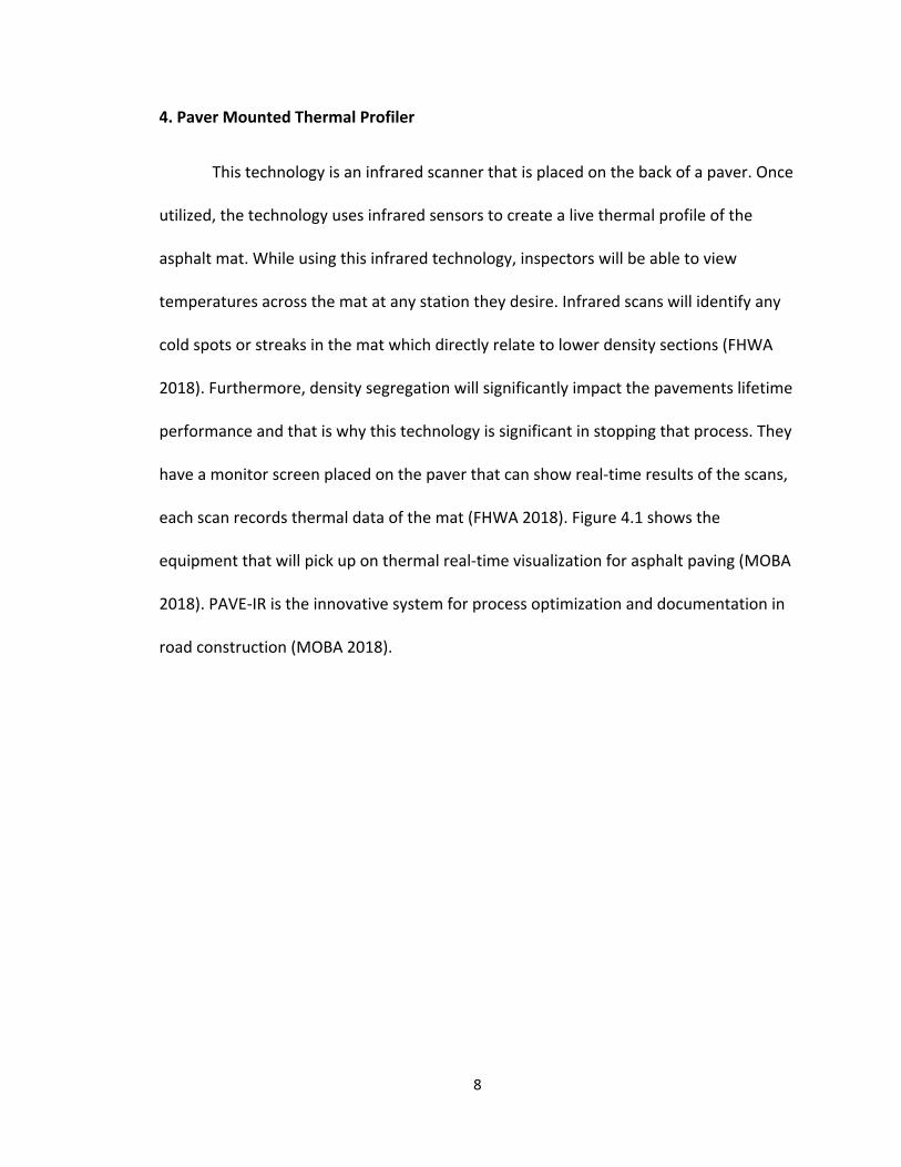
4. Paver Mounted Thermal Profiler
This technology is an infrared scanner that is placed on the back of a paver. Once
utilized, the technology uses infrared sensors to create a live thermal profile of the
asphalt mat. While using this infrared technology, inspectors will be able to view
temperatures across the mat at any station they desire. Infrared scans will identify any
cold spots or streaks in the mat which directly relate to lower density sections (FHWA
2018). Furthermore, density segregation will significantly impact the pavements lifetime
performance and that is why this technology is significant in stopping that process. They
have a monitor screen placed on the paver that can show real‐time results of the scans,
each scan records thermal data of the mat (FHWA 2018). Figure 4.1 shows the
equipment that will pick up on thermal real‐time visualization for asphalt paving (MOBA
2018). PAVE‐IR is the innovative system for process optimization and documentation in
road construction (MOBA 2018).

9
Figure 4.1: Smart Paver (MOBA 2018)
Personnel also have the option to place additional sensors on equipment, such
as on the compactor, back of the dump trucks, on the screed, in the hopper, and so
forth. With this thermal visualization, the construction now has insights into the quality
of the material being laid. MOBA Mobile Automation delivers a breakdown of the
system’s components in which they accurately depict what each component can sustain
and deliver to the entire innovative technology shown in Figure 4.2 (MOBA 2018). If
there are differences in the material being laid, immediate measures can be taken to
correct the road. This technology is also compatible with every paver. There exist three
main competences of the infrared scanner, “high‐precision data acquisition with
innovative cloud solution linked to open interfaces for current asphalt logistics and
process systems, as well as a highly scalable reporting system” (MOBA 2018). This
combination of the innovative tool accurately depicts measurement to evaluation.

10
Figure 4.2: MOBA System Components (MOBA 2018)

11
There have been several other DOT’s to successfully utilize infrared temperature
monitoring on a pilot project including Iowa and Texas. Pave‐IR run by MOBA Mobile
Automation appear to be the only company competing in the field of providing
temperatures across the asphalt mat in real time on a monitor displayed onboard the
paver. This entire system would cost roughly $34K for each pavement operation or $18K
to rent the equipment for a 2 month project. The price for a rental of the equipment
covers a $3,000 installation charge, plus an additional $7,500 charge per month of rental
(Appendix A). Devices such as a Microsoft Tablet will allow an inspector to see the
pavement data given, Java, Adobe, and MOBA Pave Project have been installed on the
device. This will allow for data transmission as close to real time as possible. Eventually
with the help of this equipment among others being implemented in this project,
technicians will be able to monitor and inspect resurfacing projects without having to be
on site. Allowing them to become more efficient and able to inspect multiple projects
simultaneously (MOBA 2018).
12
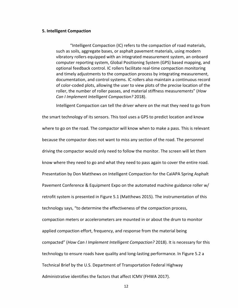
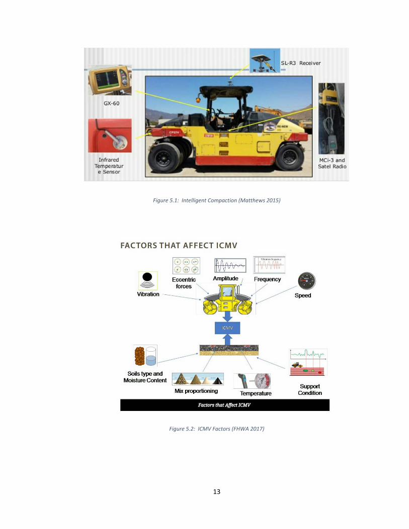
5. Intelligent Compaction
“Intelligent Compaction (IC) refers to the compaction of road materials, such as soils, aggregate bases, or asphalt pavement materials, using modern vibratory rollers equipped with an integrated measurement system, an onboard computer reporting system, Global Positioning System (GPS) based mapping, and optional feedback control. IC rollers facilitate real‐time compaction monitoring and timely adjustments to the compaction process by integrating measurement, documentation, and control systems. IC rollers also maintain a continuous record of color‐coded plots, allowing the user to view plots of the precise location of the roller, the number of roller passes, and material stiffness measurements” (How Can I Implement Intelligent Compaction? 2018).
Intelligent Compaction can tell the driver where on the mat they need to go from
the smart technology of its sensors. This tool uses a GPS to predict location and know
where to go on the road. The compactor will know when to make a pass. This is relevant
because the compactor does not want to miss any section of the road. The personnel
driving the compactor would only need to follow the monitor. The screen will let them
know where they need to go and what they need to pass again to cover the entire road.
Presentation by Don Matthews on Intelligent Compaction for the CaIAPA Spring Asphalt
Pavement Conference & Equipment Expo on the automated machine guidance roller w/
retrofit system is presented in Figure 5.1 (Matthews 2015). The instrumentation of this
technology says, “to determine the effectiveness of the compaction process,
compaction meters or accelerometers are mounted in or about the drum to monitor
applied compaction effort, frequency, and response from the material being
compacted” (How Can I Implement Intelligent Compaction? 2018). It is necessary for this
technology to ensure roads have quality and long‐lasting performance. In Figure 5.2 a
Technical Brief by the U.S. Department of Transportation Federal Highway
Administrative identifies the factors that affect ICMV (FHWA 2017).
13
Figure 5.1: Intelligent Compaction (Matthews 2015)
Figure 5.2: ICMV Factors (FHWA 2017)
14
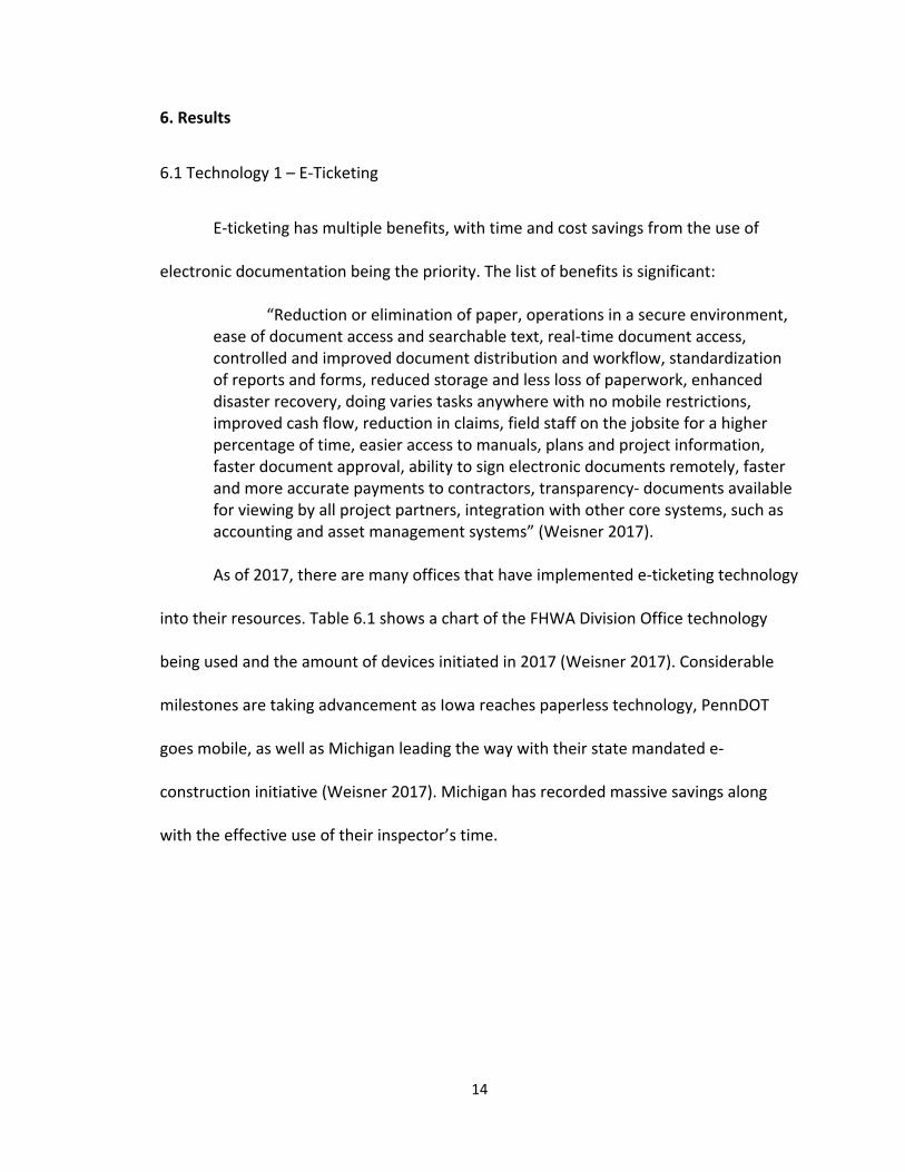
6. Results
6.1 Technology 1 – E‐Ticketing
E‐ticketing has multiple benefits, with time and cost savings from the use of
electronic documentation being the priority. The list of benefits is significant:
“Reduction or elimination of paper, operations in a secure environment, ease of document access and searchable text, real‐time document access, controlled and improved document distribution and workflow, standardization of reports and forms, reduced storage and less loss of paperwork, enhanced disaster recovery, doing varies tasks anywhere with no mobile restrictions, improved cash flow, reduction in claims, field staff on the jobsite for a higher percentage of time, easier access to manuals, plans and project information, faster document approval, ability to sign electronic documents remotely, faster and more accurate payments to contractors, transparency‐ documents available for viewing by all project partners, integration with other core systems, such as accounting and asset management systems” (Weisner 2017).
As of 2017, there are many offices that have implemented e‐ticketing technology
into their resources. Table 6.1 shows a chart of the FHWA Division Office technology
being used and the amount of devices initiated in 2017 (Weisner 2017). Considerable
milestones are taking advancement as Iowa reaches paperless technology, PennDOT
goes mobile, as well as Michigan leading the way with their state mandated e‐
construction initiative (Weisner 2017). Michigan has recorded massive savings along
with the effective use of their inspector’s time.

15
Table 6.1: Technologies Used by DOTs (Weisner 2017)
Iowa DOT inspectors claimed that, “we have the ability to send out automatic
emails and texts when orders are placed, deliveries are loaded, and orders are
completed. Customers can sign in and track their trucks to the job” and also
communicating the frequent time management this electronic tool saves, “if you’ve
ever worked with concrete, you know it hardens over time. There is a window at which
the concrete must be poured for it to be acceptable to use on one of our projects. Now
the inspector can more closely monitor the timing of deliveries for quality control” (Iowa
DOT 2016). Iowa plans to work with their industry partners closely to communicate
when they’re material ships, processes, and enters the project.
16
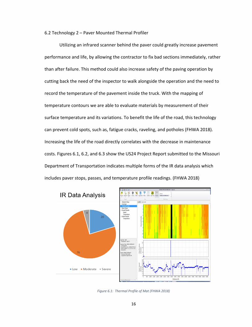
6.2 Technology 2 – Paver Mounted Thermal Profiler
Utilizing an infrared scanner behind the paver could greatly increase pavement
performance and life, by allowing the contractor to fix bad sections immediately, rather
than after failure. This method could also increase safety of the paving operation by
cutting back the need of the inspector to walk alongside the operation and the need to
record the temperature of the pavement inside the truck. With the mapping of
temperature contours we are able to evaluate materials by measurement of their
surface temperature and its variations. To benefit the life of the road, this technology
can prevent cold spots, such as, fatigue cracks, raveling, and potholes (FHWA 2018).
Increasing the life of the road directly correlates with the decrease in maintenance
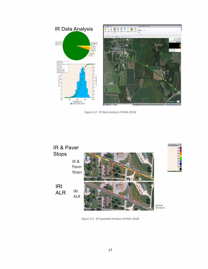
costs. Figures 6.1, 6.2, and 6.3 show the US24 Project Report submitted to the Missouri
Department of Transportation indicates multiple forms of the IR data analysis which
includes paver stops, passes, and temperature profile readings. (FHWA 2018)
Figure 6.1: Thermal Profile of Mat (FHWA 2018)
17
Figure 6.2: IR Data Analysis (FHWA 2018)
Figure 6.3: IR Expanded Analysis (FHWA 2018)

18
Data processing and reports will maintain the raw temperature profile of the
analysis zone, paving area, and sensor width. There are “three steps to eliminate invalid
temperature measurements: 1. Eliminate measurement locations within 2 feet of the
mat’s edge, eliminate temperature readings less than 170 Fahrenheit and greater than
400 Fahrenheit, and eliminate data with paver stops greater than 60 Seconds” (FHWA
2018). Studies found by the SHRP2 RO6C that “properly installed and maintained tarps
significantly reduced the temperature differentials by about 40%” which could show
advantage in our study (FHWA 2018). The feedback that was posted in the webinar by
the SHRP2 RO6C Technology to Enhance Quality Control on Asphalt Pavements quoted
some noteworthy reviews from customers, stating, “the scanner helps in adding trucks
for increased uniformity, adjusting practices, and shows the benefits of short hauling;
the scanner data is a vivid tool for showing how readability is influenced by the
uniformity of temperatures” and “the IR scanner technology saves one grind of a
project, the equipment paid for itself; Maine DOT” (FHWA 2018). However, it must be
considered for quality thermal readings that the proper equipment is used and
purchased. Trucks with good beds, MTV’s with remixing capability, paved automation,
and so forth will make the Paver Mounted Thermal Profiler perform adequately.
19
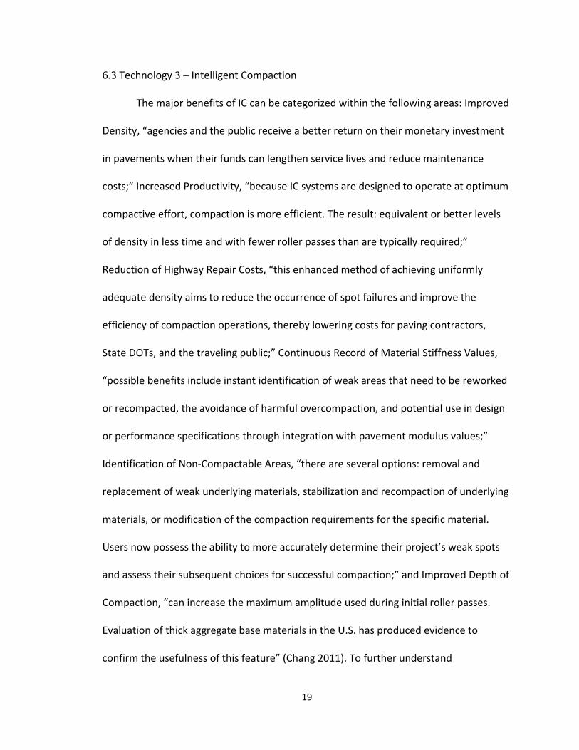
6.3 Technology 3 – Intelligent Compaction
The major benefits of IC can be categorized within the following areas: Improved
Density, “agencies and the public receive a better return on their monetary investment
in pavements when their funds can lengthen service lives and reduce maintenance
costs;” Increased Productivity, “because IC systems are designed to operate at optimum
compactive effort, compaction is more efficient. The result: equivalent or better levels
of density in less time and with fewer roller passes than are typically required;”
Reduction of Highway Repair Costs, “this enhanced method of achieving uniformly
adequate density aims to reduce the occurrence of spot failures and improve the
efficiency of compaction operations, thereby lowering costs for paving contractors,
State DOTs, and the traveling public;” Continuous Record of Material Stiffness Values,
“possible benefits include instant identification of weak areas that need to be reworked
or recompacted, the avoidance of harmful overcompaction, and potential use in design
or performance specifications through integration with pavement modulus values;”
Identification of Non‐Compactable Areas, “there are several options: removal and
replacement of weak underlying materials, stabilization and recompaction of underlying
materials, or modification of the compaction requirements for the specific material.
Users now possess the ability to more accurately determine their project’s weak spots
and assess their subsequent choices for successful compaction;” and Improved Depth of
Compaction, “can increase the maximum amplitude used during initial roller passes.
Evaluation of thick aggregate base materials in the U.S. has produced evidence to
confirm the usefulness of this feature” (Chang 2011). To further understand

20
overcompaction, it is defined by the “crushing of aggregate or low air void content,
leading to rutting or flushing” (Sommerfeldt 2018). In Figure 6.4, the IC Road Map
outlines the most efficient way to begin implementing IC—these strategies will help
overcome potential gaps or barriers (How Can I Implement Intelligent Compaction?
2018).
Figure 6.4: IC Implementation (How Can I Implement Intelligent Compaction? 2018)

21
7. The Connection Between the Technologies
In this study, these intelligent devices will coincide together in creating an
optimal construction project. These technologies aim to increase productivity, safety,
quality, and overall, the life‐expectancy of the road. Each of these technologies are
unique, but will benefit the State greatly. The State will receive better quality roads, be
able to keep track of the project, and know the details of progress, what materials are
needed, timeline of completion to communicate to the public, and the cost. E‐ticketing
will help contractors remain in contact with their workers to check on their headway.
Figure 7.1 shows what an ideal e‐ticket would look like once received electronically. This
also allows contractors knowledge of load time to hold workers accountable (Iowa DOT
2016). Contractors will be able to determine why trucks are late (whether it be traffic
situations, off‐task breaks, etc.), and how many trucks they need on the project. By
knowing this information ahead of time, contractors will be able to find discrepancy,
hold accountability, and spend money more wisely. “Unlike traditional random
sampling, continuous testing uses multiple inputs to ‘look for’ failure zones and has a
high probability of detecting defects before they lead to premature failures”
(Sommerfeldt 2018). Figure 7.2 shows continuous sampling can cover 100% of the mat.
An example of the technologies utilized in practice developed in the “beginning (of)
2016, Alaska DOT used the IC and PAVE‐IR paver‐mounted thermal scanner technologies
as contractor pay factors as part of project acceptance… They plan to offer bonuses for
increasing the asphalt compaction averages – and require remediation for compaction
below the standards” (Sommerfeldt 2018).

22
Figure 7.1: E‐Ticket (Iowa DOT 2016)
Figure 7.2: Intelligent Compaction Results (Willoughby 2014)

23
Another advantage of these technologies is to hopefully reduce the number of
fines. For example, if the State tests the road during the trucks initially paving it, and
they fail the density test, the contractor is fined. While using intelligent compaction and
the paver mounted thermal profiler, personnel can adjust problems by using real‐time
screening from their sensors to re‐correct the road. Therefore, a better quality road
during the project equals less potential fines. The goals of these two technologies
working together is early detection of mistakes and possible weakness in the
development of the road. If the contractors invest the money initially, the technology
will pay off in the long run. Contractors will have less future maintenance of the road
and the State will no longer have to continuously rehire for preservation. In favor,
contractors will have a better product and potentially gain jobs outside of state due to
their quality project development. In Figure 7.3, the Kentucky Transportation Cabinet
identifies the amount of infrastructure they must maintain and improve. The State has
little resources to keep up with this growing statistic, hopefully with the help of
technological advancements they will be able to reduce costs and enhance longevity.
Figure 7.3: KYTC Statement (Kentucky.gov 2018)

24
Continuing, these technologies should ideally all be accessible wirelessly.
Eventually, the future outcome would be to get them all on the same application
working simultaneously together. Of course they would need to get the licensing to
work together. However, this would promise to be more convenient and less systems to
look at. It would also be desirable to cut back on an inspector having to be at the job site
every day because the abilities from the implemented technologies would cover a large
percentage of the work an inspector has to do. Fundamentally, the devices will allow
technicians to cover multiple jobs at once. They will help inspectors report immediately
if there is a delay or issue in production.
25
Safety will be a large benefactor with these technologies. Inspectors will no
longer have to walk up to the truck to get a loading ticket, where incoming traffic in
their lane can be a concern or the truck itself, so they are safer using the e‐ticketing
process. Secondly, they will not have to measure the temperature of the mat because
the infrared scanner will detect it for them and display and record it on a smart‐device.
It can be quite dangerous for inspectors to travel between paver equipment and roller
machines, especially if the operator cannot see them. Thirdly, this can prevent
inspectors from a fall or a trip onto the mat where they may get burned from the high
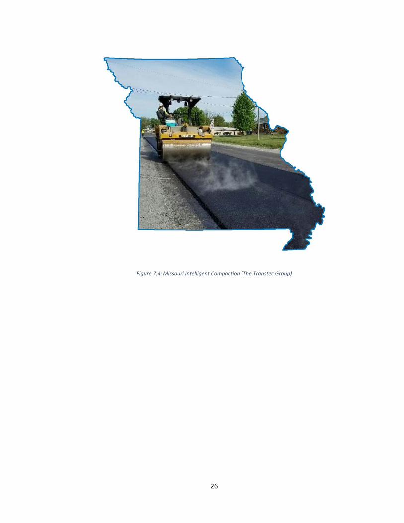
temperatures of the asphalt. Figure 7.4 shows in the intelligent compaction and infrared
scanning field projects, submitted by the Missouri Department of Transportation, with
heat rising off of the mat from the intense temperature of the asphalt being laid and the
dangers that it can lead to (The Transtec Group 2018). Due to intelligent compaction
and paver mounted thermal profiler technology the inspectors do not need to get close
to measure for cold spots or density issues, but rather read the data from a screen. In
conclusion, these technologies can save a lot of time by preventing testing stops due to
uncertainty and collect data continuously throughout the whole project to see the
progress while keeping inspectors safe.
26
Figure 7.4: Missouri Intelligent Compaction (The Transtec Group)

27
8. Limitations
There are limitations to consider. There is a possibility of inconsistent data
exchange, which would not relay the data correctly. A disconnection between
information abstracted from the paver to the tablet or other smart device, data base
information retrieval lost, or hardware connection problems (such as the GPS) losing
service could throw off the collection of data. There will always be technical challenges
that impede construction, but corrections can be made to prevent these issues, such as
working with cell‐phone providers to get towers stationed nearby or Microsoft
programs to update software to possibly decrease lagging. Because of the advancement
of this technology, companies will struggle to adapt due to their reluctance to change. A
limitation on the technological device of intelligent compaction can be identified with:
“The growing interest among transportation agencies and contractors to incorporate IC technologies into earthwork and HMA pavement construction practice. Expectations are that the IC systems will: 1) improve construction efficiency; 2) streamline quality management programs of earthwork and asphalt projects; 3) provide a link between quality acceptance parameters and pavement design parameters; and 4) improve the performance of compacted materials. These expectations cannot be met without addressing the following key implementation challenges, such as: lack of adequate knowledge about technical aspects; no widely accepted specifications or standards; limited number of well‐documented case histories demonstrating the benefits of IC; inadequate education/training materials” (White 2010).
28
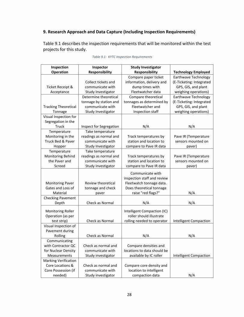
9. Research Approach and Data Capture (Including Inspection Requirements)
Table 9.1 describes the inspection requirements that will be monitored within the test projects for this study.
Inspection Operation
Inspector Responsibility
Study Investigator Responsibility Technology Employed
Ticket Receipt & Acceptance
Collect tickets and communicate with Study Investigator
Compare paper ticket information, delivery and
dump times with Fleetwatcher data
Earthwave Technology (E‐Ticketing: Integrated GPS, GIS, and plant weighing operations)
Tracking Theoretical Tonnage
Determine theoretical tonnage by station and communicate with Study Investigator
Compare theoretical tonnages as determined by
Fleetwatcher and Inspection staff
Earthwave Technology (E‐Ticketing: Integrated GPS, GIS, and plant weighing operations)
Visual Inspection for Segregation in the
Truck Inspect for Segregation N/A N/A
Temperature Monitoring in the Truck Bed & Paver
Hopper
Take temperature readings as normal and communicate with Study Investigator
Track temperatures by station and location to compare to Pave IR data
Pave IR (Temperature sensors mounted on
paver)
Temperature Monitoring Behind the Paver and
Screed
Take temperature readings as normal and communicate with Study Investigator
Track temperatures by station and location to compare to Pave IR data
Pave IR (Temperature sensors mounted on
paver)
Monitoring Paver Gates and Loss of
Material
Review theoretical tonnage and check
paver
Communicate with inspection staff and review Fleetwatch tonnage data. Does theoretical tonnage
raise "red flags?" N/A
Checking Pavement Depth Check as Normal N/A N/A
Monitoring Roller Operation (as per
test strip) Check as Normal
Intelligent Compaction (IC) roller should illustrate
rolling needed to operator Intelligent Compaction
Visual Inspection of Pavement during
Rolling Check as Normal N/A N/A
Communicating with Contractor QC for Nuclear Density Measurements
Check as normal and communicate with Study investigator
Compare densities and locations to data should be
available by IC roller Intelligent Compaction
Marking Verification Core Locations & Core Possession (if
needed)
Check as normal and communicate with Study investigator
Compare core density and location to intelligent compaction data N/A
Table 9.1: KYTC Inspection Requirements

29
The following proposed tasks indicate how this study will be approached:
Task 1: Work with District 7 management to identify three to five test projects.
Task 2: Add the special notes for using e‐Ticketing, PaveIR, and Intelligent Compaction
to the bid packages of the selected test projects. Special notes for all technologies are
attached in the Appendix B, C, and D.
Task 3: Work with the District 7 staff and contractors to plan and initiate the study plan,
gain or plan access to the data, and communicate schedule and timelines.
Task 4: Communicate schedules of paving operations with the Study Investigators.
Task 5: Study Investigators will observe and collect data during the paving operations of
the test projects as described in the table above.
Task 6: Tonnage, delivery, temperature, and compaction data will be compared and
reported.
Task 7: A final evaluation the data and technology used will be reported.

30
10. Potential Outcomes
This study, implementing the three technologies, could potentially provide
enough data analysis to show significant improvement and progress made in the project
that would help reduce the workload on inspection staff, increase safety and
communication, and amplify road quality. While also, hopefully allowing a reduction in
spending. With the State having less and less resources to contribute to jobs,
implementing these technologies is a unique and beneficial alternative to the problem.
Furthermore, with the ability to run jobs without a technician on site at all times the
State will be save in cost and heighten safety satisfaction. Communication between
contractors, industry, personnel, and the project site will increase when keeping better
track of the trucks at the job, getting rid of paperwork, and having on‐hand, real‐time
progress of the job.

31
11. Conclusion
As technology develops throughout the world, transportation is constantly
having to keep up with the demands of growth and efficiency while maintaining a cost‐
effective project that is safe and allows for a quality life‐expectancy. The three
technologies discussed in this thesis have been proven to be beneficial through research
and application. E‐Ticketing can eliminate paper, enable real‐time document use, create
viewing availability for all project partners, and maintain a safer work environment. The
Paver Mounted Thermal Profiler allows contractors to fix defective sections
immediately, evaluate materials by measurement of their surface temperature and its
variations, and benefit the life of the road by detecting cold spots, increasing the life of
the road and saving on maintenance costs. Lastly, Intelligent Compaction is one of the
most important processes in transportation construction, which strengthens and
stabilizes uniformity of pavement materials, and in turn, achieves a durable roadway.
Implementing this technology would significantly impact roadway construction,
efficiency, cost, safety, and time management. The Kentucky Department of
Transportation would benefit from these technological advances in the long run due to
producing stronger, quality roads and developing a faster system that saves in resources
while communicating data systematically with all partners involved.

32
Appendices
Appendix A: MOBA Paver Mounted Thermal Profiler Estimate

33

34
Appendix B: E‐Ticketing Special Note
SPECIAL NOTE FOR HMA ELECTRONIC DELIVERY MANAGEMENT SYSTEM (HMA e-Ticketing)
This Special Note will apply when indicated on the plans or in the proposal. Section references herein are to the Department’s Standard Specifications for Road and Bridge Construction current edition.
1.0 DESCRIPTION. Incorporate a GPS Fleet Management System for all HMA delivered to the project in order to monitor, track, and report loads of HMA during the construction processes from the point of measurement and loading to the point of incorporation to the project. 2.0 MATERIALS AND EQUIPMENT. Submit to the Engineer for approval, no fewer than 30 days prior to HMA placement activities, a GPS fleet management system supplier that can provide a qualified representative for on-site technical assistance during the initial setup, pre-construction verifications, and data management and processing as needed during the Project to maintain equipment.
Provide operator settings, user manuals, training videos, and required viewing/export software for review. Provide equipment that will meet the following:
1. A wireless fleet management or GPS device that is capable of tracking all delivery trucks (both company-owned and third-party) must be installed on all trucks and equipment (dump trucks, belly dumps, side-load dumps, transfer vehicles, pavers, or any other trucks/vehicles) used to transfer and incorporate HMA into the project. KYTC personnel shall have the ability to access Real Time monitoring through the use of a mobile device such as an iPad, smartphone, etc.
2. The fleet management system shall be fully integrated with the Contractor’s Load Read-Out scale system at the HMA plant site.
3. The fleet management system shall have the ability to measure and track vehicles and their contents (weights and material types) continuously from the plant site to the project site. The system shall have internal battery backup capabilities due to loss of power, and have the ability to store data if GPS connectivity is lost and transmit that same data when unit re-establishes connectivity. To be considered continuous, no two data points shall be more than 60 seconds apart unless the vehicle is stopped. Duration of stop time for any reason shall be recorded. The fleet management system shall have the ability to track the engagement of the truck PTO to indicate the dump the material.
3.0 CONSTRUCTION. Provide the Engineer with the manufacturer’s specifications and all required documentation for data access at the pre-construction conference.
A. Construction Requirements 1. Install and operate equipment in accordance with the manufacturer’s specifications.
2. Verify the GPS is working within the requirements of this Special Note.

35
B. Data Deliverables Provide to the Engineer a means in which to gather report summaries by way of iOS apps, web pages, or any other method at the disposal of the Engineer. The Engineer may request data at any time during paving operations.
1. Real-time Continuous Data Items Provide the Engineer access to a GIS map-based data viewer which displays the following information in real-time with a web-based system compatible with iOS and Windows environments.
Each Truck UniqueTruck ID Truck status
Time At Source Time At Destination Time At Paver Time At Scale Time to and from plant/job Time of PTO engagement Time Stopped with Engine Running
Time of last transmission Location (Latitude and Longitude in decimal degrees to
nearest 0.0000001) every 60 seconds Description of Material being transported (i.e. asphalt
base, asphalt surface) Mix Design Number Net Weight of material being transported to the nearest
0.01 ton Running Daily Total of Net Weight of material being
transported to nearest 0.01 ton. Project Number
Scale Location Project Location Point of Delivery (i.e. paver)
2. Daily Summary The following summary information shall be provided to the Engineer electronically within 4 hours of beginning operations on the next working day
o For each Material List of Individual Loads
Contractor Name Project Number Unique Truck ID Net Weight For Payment (nearest 0.01 tons) Date Mix Temperature at Time of Loading, Fahrenheit Time Loaded Time Unloaded Delivery Location (Latitude/Longitude in decimal degrees to nearest
0.0000001)

36
o For each Bid Item Total Quantity for Payment (nearest 0.01 tons)
4.0 MEASUREMENT. The Department will measure the HMA electronic delivery management system as a lump sum item.
5.0 PAYMENT. The Department will make payment for the completed and accepted quantities under the following:
1. Payment is full compensation for all work associated with providing all required equipment, training, and documentation.
2. Delays due to GPS satellite reception of signals or equipment breakdowns will not be considered justification for contract modifications or contract extensions.
3. Payment will be full compensation for costs related to providing the GPS system, including all equipped pavers and transfer vehicles, integration with plant load-out systems, and any software required for the construction and reporting process. All quality control procedures including the GPS systems representative’s technical support and on-site training shall be included in the Contract lump sum price.
Code Pay Item Pay Unit
HMA ELECTRONIC DELIVERY MANAGEMENT SYSTEM EACH
37
Appendix C: Paver Mounted Thermal Profiler Special Note
SPECIAL NOTE FOR PAVER MOUNTED TEMPERATURE PROFILES
This Special Note will apply when indicated on the plans or in the proposal. Section references herein are to the Department’s Standard Specifications for Road and Bridge Construction current edition. 1.0 DESCRIPTION. Provide paver mounted infrared temperature equipment to continually monitor the temperature of the asphalt mat immediately behind all paver(s) during the placement operations for all driving lanes (including ramps for Interstates and Parkways) within the project limits. Provide thermal profiles that include material temperature and measurement locations. Provide equipment measuring material temperature within the paver hopper and at the vibratory screed.
2.0 MATERIALS AND EQUIPMENT. In addition to the equipment specified in Subsection 403.02 utilize a thermal equipment supplier that can provide a qualified representative for onsite technical assistance during the initial setup, pre-construction verification, and data management and processing as needed during the project to maintain equipment within specifications and requirements.
Provide operator settings, user manuals, required viewing/export software for analysis. Ensure the temperature equipment will meet the following:
1. A device with one or more infrared sensors that is capable of measuring in at least 1 foot intervals across the paving width, with a minimum width of 12 feet, or extending to the recording limits of the equipment, whichever is greater. A Maximum of two (2) brackets are allowed in the influence area under the sensors. A temperature profile must be made on at least 1 foot intervals longitudinally down the road;
2. Infrared sensor(s): Measuring from 32°F to 400°F with an accuracy of ± 2.0% of the sensor reading;
3. Ability to measure the following: The placement distance using a Global Positioning System (GPS) or a Distance
Measuring Instrument (DMI) and a Global Positioning System (GPS) Stationing;
4. GPS: Accuracy ± 4 feet in the X and Y Direction; 5. Latest version of software to collect, display, retain and analyze the mat temperature readings
during placement. The software must have the ability to create and analyze: Full collected width of the thermal profiles, Paver speed and Paver stops and duration for the entire Project;
6. Ability to export data automatically to a remote data server; At the preconstruction meeting, provide the Department with rights to allow for web access to the data server. This web-based software must also provide the Department with the ability to download the raw files and software and to convert them into the correct format.
The thermal profile data files must provide the following data in a neat easy to read table format: Project information including Road Name and Number, PCN, Beginning and Ending MPs. IR Bar Manufacturer and Model number Number of Temperature Sensors (N) Spacing between sensors and height of sensors above the asphalt mat Total number of individual records taken each day (DATA BLOCK) Date and Time reading taken Latitude and Longitude Distance paver has moved from last test location Direction and speed of the paver Surface temperature of each of the sensors
38
3.0 CONSTRUCTION. Provide the Engineer with all required documentation at the pre-construction conference.
1. Install and operate equipment in accordance with the manufacturer’s specifications.
2. Verify that the temperature sensors are within ± 2.0% using an independent temperature device on a material of known temperature. Collect and compare the GPS coordinates from the equipment with an independent measuring device.
Ensure the independent survey grade GPS measurement device is calibrated to the correct coordinate system (using a control point), prior to using these coordinates to validate the equipment GPS.
The comparison is considered acceptable if the coordinates are within 4 feet of each other in the X and Y direction.
3. Collect thermal profiles on all Driving Lanes during the paving operation and transfer the data to the “cloud” network or if automatic data transmission is not available, transfer the data to the Engineer at the end of daily paving.
4. Contact the Department immediately when System Failure occurs. Daily Percent Coverage will be considered zero when the repairs are not completed within two (2) working days of System Failure. The start of this two (2) working day period begins the next working day after System Failure.
5. Evaluate thermal profile segments, every 150 feet, and summarize the segregation of temperature results. Results are to be labeled as Minimal 0°25°F, Moderate 25.1° 50°F and Severe >50°. Severe readings over 3 consecutive segments or over 4 or more segments in a day warrant investigation on the cause of the differential temperature distribution.
4.0 MEASUREMENT. The Department will measure the total area of the driving lanes mapped by the infrared scanners. Full payment will be provided for all driving lanes with greater than 85% coverage. Partial payment will be made for all areas covered from 50% coverage to 85% coverage at the following rate Coverage area percentage X Total bid amount. Area with less than 50% coverage will not be measured for payment.
5.0 PAYMENT. The Department will make payment for the completed and accepted quantities under the following:
1. Payment is full compensation for all work associated with providing all required equipment, training, and documentation.
2. Delays due to GPS satellite reception of signals or equipment breakdowns will not be considered justification for contract modifications or contract extensions.
Code Pay Item Pay Unit
24891EC PAVE MOUNT INFRARED TEMP EQUIPMENT SQFT

39
Appendix D: Intelligent Compaction Special Note
SPECIAL NOTE FOR INTELLIGENT COMPACTION OF ASPHALT MIXTURES
This Special Note will apply when indicated on the plans or in the proposal.
Section references herein are to the Department’s Standard Specifications for Road and Bridge Construction current edition.
1.0 DESCRIPTION. Provide and use Intelligent Compaction (IC) Rollers for compaction of all asphalt mixtures.
2.0 MATERIALS AND EQUIPMENT. In addition to the equipment specified in Subsection 403.02, a minimum of one (1) IC roller is to be used on the project at all times. The Contractor may elect to only use one (1) IC roller for compaction, but two (2) IC rollers are preferred as any combination of the breakdown, intermediate and finish rollers in the roller train. All IC rollers will meet the following minimum characteristics:
1) Are self- propelled double-drum vibratory rollers equipped with
accelerometers mounted in or about the drum to measure the interactions between the rollers and compacted materials in order to evaluate the applied compactive effort. The IC rollers must have the approval of the Engineer prior to use. Examples of rollers equipped with IC technology can be found at www.IntelligentCompaction.com.
2) Are equipped with non-contact temperature sensors for measuring
pavement surface temperatures.
3) The output from the roller is designated as the IC-MV which represents the stiffness of the materials based on the vibration of the roller drums and the resulting response from the underlying materials.
4) Are equipped with integrated on-board documentation systems that are
capable of displaying real-time color-coded maps of IC measurement values including the stiffness response values, location of the roller, number of roller passes, machine settings, together with the material temperature, speed and the frequency and amplitude of roller drums. Ensure the display unit is capable of transferring the data by means of a USB port or through wireless transmission.
5) Are equipped with a mounted Global Positioning System GPS radio and
receiver either a Real Time Kinematic (RTK-GPS) or Global Navigational Satellite System (GNSS) units that monitor the location and track the number of passes of the rollers. Accuracy of the positioning system is to be a minimum of 12 inches.
3.0 WORK PLAN. Submit to the Engineer an IC Work Plan at the Preconstruction Conference and at least 2 weeks prior to the beginning of construction. Describe in the work plan the following:
1. Compaction equipment to be used including:
• Vendor(s) • Roller model(s), • Roller dimensions and weights, • Description of IC measurement system, • GPS capabilities • Documentation system,

40
• Temperature measurement system, and • Software.
2. Roller data collection methods including sampling rates and intervals and data file types. 3. Transfer of data to the Engineer including method, timing, and personnel responsible. Data transfer shall occur at minimum twice per day or as directed by the Engineer and is to be electronic.
4. Training plan and schedule for roller operators, project foreman, project surveyors, quality control technicians, and Cabinet personnel including project engineers and field inspectors; including both classroom and field training. Training should be conducted at least 1 week before beginning IC construction. The training is to be performed by a qualified representative(s) from the IC Roller manufacture(s) to be used on the project. The training should be 4-8 hours in duration and minimum training topics shall include:
1. Background information for the specific IC system(s) to be used
2. Setup and checks for IC system(s), GPS receiver, base-station and hand held rovers
3. Operation of the IC system(s) on the roller; i.e., setup data collection, start/stop of data recording, and on-board display options
4. Transferring raw IC data from the rollers(s)
5. Operation of vendor’s software to open and view raw IC data files and exporting all-passes and proofing data files in Veda-compatible format
6. Operation of Veda software to import the above exported all-passes and proofing data files, inspection of IC maps, input point test data, perform statistics analysis, and produce reports for project requirements
7. Coverage and uniformity requirements
4.0 CONSTRUCTION. Do not begin work until the Engineer has approved the IC submittals and the IC equipment.
Follow requirements established in Section 400 for production and placement, materials, equipment, acceptance plans and adjustments except as noted or modified in this Specification. Provide the Engineer at least one day’s notice prior to beginning construction or prior to resuming production if operations have been temporarily suspended. Ensure paving equipment complies with all requirements specified in Section 400. The IC roller temperatures will be evaluated by the Department with the data from a Paver Mounted Infrared Temperature Gauge.
A. Pre-Construction Test Section(s) Requirements
1. Prior to the start of production, ensure the proper setup of the GPS, IC roller(s) and the rover(s) by conducting joint GPS correlation and verification testing between the Contractor, GPS representative and IC roller manufacturer using the same datum.

41
1. Ensure GPS correlation and verification testing includes the following minimum processes:
a. Establish the GPS system to be used either one with a base station
or one with mobile receivers only. Ensure all components in the system are set to the correct coordinate system; then,
b. Verify that the roller and rover are working properly and that there is
a connection with the base station; then,
c. Record the coordinates of the two edges where the front drum of the roller is in contact with the ground from the on-board, color-coded display; then,
d. Mark the locations of the roller drum edges and move the roller,
and place the mobile receiver at each mark and record the readings; then,
2. Compare coordinates between the roller and rover receivers. If the
coordinates are within 12.0 in. of each other, the comparison is acceptable. If the coordinates are not within 12.0 in., diagnose and perform necessary corrections and repeat the above steps until verification is acceptable.
3. Do not begin work until acceptable GPS correlation and verification has
been obtained.
4. The Contractor and the Department should conduct random GPS verification testing during production to ensure data locations are accurate. The recommended rate is once per day with a requirement of at least once per week.
5. All acceptance testing shall be as outlined in Standard Specifications Section 400.
B. Construction Test Section(s) Requirements
Construct test section(s) at location(s) agreed on by the Contractor and the Engineer within the project limits. The test section is required to determine a compaction curve of the asphalt mixtures in relationship to number of roller passes and to the stiffness of mixture while meeting the Department in-place compaction requirements. All rollers and the respective number of passes for each is to be determined via control strip each time a material change, equipment change or when the Engineer deems necessary.
Conduct test section(s) on every lift and every asphalt mixture. Ensure test section quantities 1,000 tons of mainline mixtures. Operate IC rollers in the low to medium amplitude range and at the same settings (speed, frequency) throughout the section while minimizing overlapping of the roller, the settings are to be used throughout the project with no changes. After each roller pass, the qualified technician from the contractor observed by the Department will use a nondestructive nuclear gauge that has been calibrated to the mixture to estimate the density of the asphalt at 10 locations uniformly spaced throughout the test section within the width of a single roller pass. The density readings and the number of roller passes needed to achieve the specified compaction will be recorded. The estimated target density will be the peak of the average of the nondestructive readings within the desired compaction temperature range for the mixture. The IC roller data in conjunction with the Veda software will create an

42
IC compaction curve for the mixture. The target IC-MV is the point when the increase in the IC-MV of the material between passes is less than 5 percent on the compaction curve. The IC compaction curve is defined as the relationship between the IC-MV and the roller passes. A compaction curve example is as follows:
Subsequent to the determination of the target IC-MV, compact an adjoining > 250 < 500 tons section using same roller settings and the number of estimated roller passes and allow the Department to verify the compaction with the same calibrated nondestructive nuclear gauge following the final roller pass. The Department will obtain cores at 10 locations, uniformly spaced throughout the test section within the width of the single roller. Obtain GPS measurement of the core locations with a GPS rover. Use the Veda software to perform least square linear regression between the core data and IC-MV in order to correlate the production IC-MV values to the Department specified in-place air voids. A sample linear regression curve example is as follows.
C. Construction Requirements Use the IC roller on all lifts and types of asphalt within the limits of the project. During construction, the Quality Control Technician shall be responsible for the following minimum functions:
1. Daily GPS check testing for the IC roller(s) and rover(s).
2. Test section construction to establish target compaction pass counts and target values for the strength of the materials using the standard testing devices; i.e., Nondestructive density gauges, pavement cores, and IC roller(s).
3. Monitoring of the construction operations and the IC roller(s) during production and final evaluation operations.
4. Quality control testing to monitor the pavement temperature and the required level of compaction.
5. Daily download and analysis of the IC data from the roller(s).
6. Daily set-up, take down and secure storage of GPS and IC roller components
Ensure the optimal number of roller passes determined from the test sections has been applied to a minimum coverage of 80% of the individual IC Construction area. Ensure a minimum of 75% of the individual IC Construction area meets the target IC-MV values determined from the test sections.
43
Do not continue paving operations if IC Construction areas not meeting the IC criteria are produced until they have been investigated by the Department. Obtain the Engineer’s approval to resume paving operations. Non-IC rollers are allowed to be used as the third roller on the project; one of the breakdown or the finish rollers is to be equipped with IC technology. The Contractor shall coordinate for on-site technical assistance from the IC roller representatives during the initial seven (7) days of production and then as needed during the remaining operations. As a minimum, the roller representative shall be present during the initial setup and verification testing of the IC roller(s). The roller representative shall also assist the Contractor with data management using the data analysis software including IC data input and processing.
IC Construction areas are defined as subsections of the project being worked continuously by the Contractor. The magnitude of the IC Construction areas may vary with production but must be at least 750 tons per mixture for evaluation. Partial IC Construction areas of < 750 tons will be included in the previous area evaluation. IC Construction areas may extend over multiple days depending on the operations.
The IC Construction Operations Criteria does not affect the Department’s acceptance processes for the materials or construction operations
5.0 MEASUREMENT. The Department will measure the total tons of asphalt mixtures compacted using the IC roller(s). Compaction is to be performed by a minimum of one IC roller, material compacted by rollers not equipped with properly functioning IC equipment will not be accepted for payment of the bid item asphalt mixtures IC rolled. Use of non-IC rollers can be accepted on small areas due to equipment malfunctions at the written approval of the Engineer. Paving operations should be suspended for equipment malfunctions that will extend over three days of operation.
6.0 PAYMENT. The Department will make payment for the completed and accepted quantities under the following:
1. Payment is full compensation for all work associated with providing IC
equipped rollers, transmission of electronic data files, two copies of IC roller manufacturer software, and training.
2. Delays due to GPS satellite reception of signals to operate the IC equipment
or IC roller breakdowns will not be considered justification for contract modifications or contract extensions.
Code Pay Item Pay Unit 24781EC Intelligent Compaction for Asphalt TON May 4th, 2015

44
References
Walton, Michael, and Others. 2030 Committee: Texas Transportation Needs Summary. Report. February 2009. Accessed April 17, 2018. https://texas2030committee.tamu.edu/documents/final_022609_execsummary.pdf.
Weisner, Kathryn, Bryan Cawley, and Alicia Sindlinger. "The Age of E‐Construction." Public Roads, July 1, 2017. August 16, 2017. Accessed March 16, 2018. https://www.fhwa.dot.gov/publications/publicroads/17julaug/02.cfm.
Iowa DOT. "ETicketing Show Promise of Speeding Process and Improving Accuracy at Asphalt Job Sites." Transportation Matters for Iowa | Iowa DOT. December 17, 2015. Accessed March 16, 2018. http://www.transportationmatters.iowadot.gov/2015/12/eticketing‐show‐promise‐of‐speeding‐process‐and‐improving‐accuracy‐at‐asphalt‐job‐sites.html.
Iowa DOT. "Improving Accountability in the Construction Process with ETicketing for Concrete Loads." Transportation Matters for Iowa | Iowa DOT. November 21, 2016. Accessed March 16, 2018. http://www.transportationmatters.iowadot.gov/2016/11/for‐iowa‐department‐of‐transportation‐inspectors‐tablet‐computers‐are‐quickly‐becoming‐the‐most‐essential‐tool‐on‐a‐construc.html.
FHWA, and AASHTO. "SHRP2 RO6C Technology to Enhance Quality Control on Asphalt Pavements: Paver Mounted Thermal Profiler." SHRP2 Solutions: Strategic Highway Research Program, January 31, 2018. MOBA. "PMTP Paver Mounted THERMAL PROFILING Asphalt Road Construction Concrete Pavers MOBA PAVE IR." MOBA Mobile Automation AG. Accessed March 16, 2018. http://moba‐automation.com/machine‐applications/asphalt‐pavers/pave‐ir/. "How Can I Implement Intelligent Compaction?" Intelligent Compaction. Accessed March 16, 2018. http://www.intelligentcompaction.com/learn/intelligent‐compaction‐fundamentals/how‐can‐i‐implement‐intelligent‐compaction/. Matthews, Donald. "Intelligent Compaction (IC) for Cold In‐Place Recycling." LinkedIn SlideShare. October 27, 2015. Accessed March 16, 2018. https://www.slideshare.net/CaliforniaAsphalt/intelligent‐compaction‐ic‐for‐cold‐inplace‐recycling.

45
FHWA. "Intelligent Compaction Measurement Values (ICMV)." Technical Brief, June/July 2017. Accessed March 16, 2018. https://www.fhwa.dot.gov/construction/ictssc/pubs/hif17046.pdf. Chang, George, and Others. "Accelerated Implementation of Intelligent Compaction Technology for Embankment Subgrade Soils, Aggregate Base, and Asphalt Pavement Materials." FHWA 12, no. 002 (July 2011). Accessed March 16, 2018. FHWA. Sommerfeldt, Rob. "Using Continuous Full Coverage Asphalt Testing to Ensure Pavement Quality." January 10, 2018. Accessed March 16, 2018. https://www.rocktoroad.com/roads‐paving/technology/using‐continuous‐full‐coverage‐asphalt‐testing‐ensures‐pavement‐quality‐5693. Willoughby, Kim, and Susan Ellis. "Intelligent Compaction Demonstration Project SR539." Accessed March 16, 2018. http://www.asphaltwa.com/wp‐content/uploads/2014/09/IC‐Demonstration‐Project‐PDF‐Version.pdf. Kentucky.gov. Accessed March 16, 2018. http://kentucky.gov/government/Pages/AgencyProfile.aspx?AgencyTitle=Kentucky Transportation Cabinet. The Transtec Group. "Intelligent Compaction and Infrared Scanning Field Projects with Consulting Support." January 2018. Accessed March 16, 2018. http://www.intelligentcompaction.com/downloads/MODOT/cmr18‐003.pdf. White, David, Pavana Vennapusa, and Heath Gieselman. "Iowa's Intelligent Compaction Research and Implementation." Iowa Department of Transportation Research News, November 2010. Accessed March 16, 2018. https://core.ac.uk/download/pdf/11353324.pdf.

46
Vita
1) Educational institutions attended and degrees already awarded:
a) University of Kentucky – Bachelor of Science in Civil Engineering (May, 2017)
2) Professional positions held:
a) Graduate Research Assistant – University of Kentucky (August 2017‐May 2018)
b) Teaching Assistant – University of Kentucky (August 2017‐May 2018)
c) Project Management Assistant – Denham Blythe (Summer 2016 and Summer
2017)
d) Summer Intern – Kentucky Transportation Cabinet (Summer 2013, Summer
2014, and Summer 2015)
3) Scholastic and professional honors:
a) Various University and outside Scholarships awarded based on merit
b) Outstanding Senior Design Team Award
c) Graduated Summa Cum Laude
4) Clyde Wesley Newcomer IV