ADVANCED SENSOR MODULE - Isabellenhütte … modes Disable Trigger Cycle running It is possible to...
43
Datasheet, Version 1.01 IVT-S 16.02.2018 [email protected] http://www.isabellenhuette.de page 1 of 43 IVT-S // HIGH PRECISION CURRENT MEASUREMENT 1. Introduction ................................................................................................................................. 1 2. Application .................................................................................................................................. 1 3. Functionality description ............................................................................................................. 2 4. Measurement description ........................................................................................................... 6 5. Technical Data .......................................................................................................................... 12 6. Mechanical Data ....................................................................................................................... 14 7. Part description / Ordering........................................................................................................ 18 8. CANbus protocol ...................................................................................................................... 19 9. Startup ...................................................................................................................................... 40 10. Index ......................................................................................................................................... 41 1. Introduction The IVT-S is a high precision current measurement system, designed for DC applications, especially for automotive application. The product is based on a modular design and provides flexibility for fast adaptations to meet customer requirements in the automotive and the industrial area. The continuous current measurement has a range up to ±2500 A. At higher currents (i.e. peaks) the measurement range will extend automatically. The shunt-based measurement method uses a 16-bit analog- digital-converter to transform the voltage drop into a digital signal. The communication is based on a CAN bus 2.0a interface. A CAN description file (CAN-dbc) is available and supports fast system integration. 2. Application The IVT-S is designed for a wide range of DC applications. For example: Hybrid and full electric drives UPS systems Stationary energy storage systems Fuel cells All battery and storage based applications
Transcript of ADVANCED SENSOR MODULE - Isabellenhütte … modes Disable Trigger Cycle running It is possible to...

Datasheet, Version 1.01 IVT-S
16.02.2018 [email protected] http://www.isabellenhuette.de
page 1 of 43
IVT-S // HIGH PRECISION CURRENT MEASUREMENT 1. Introduction ................................................................................................................................. 1 2. Application .................................................................................................................................. 1 3. Functionality description ............................................................................................................. 2 4. Measurement description ........................................................................................................... 6 5. Technical Data .......................................................................................................................... 12 6. Mechanical Data ....................................................................................................................... 14 7. Part description / Ordering........................................................................................................ 18 8. CANbus protocol ...................................................................................................................... 19 9. Startup ...................................................................................................................................... 40 10. Index ......................................................................................................................................... 41
1. Introduction
The IVT-S is a high precision current measurement system, designed for DC applications, especially for automotive application. The product is based on a modular design and provides flexibility for fast adaptations to meet customer requirements in the automotive and the industrial area. The continuous current measurement has a range up to ±2500 A. At higher currents (i.e. peaks) the measurement range will extend automatically. The shunt-based measurement method uses a 16-bit analog-digital-converter to transform the voltage drop into a digital signal. The communication is based on a CAN bus 2.0a interface. A CAN description file (CAN-dbc) is available and supports fast system integration.
2. Application
The IVT-S is designed for a wide range of DC applications. For example:
Hybrid and full electric drives
UPS systems
Stationary energy storage systems
Fuel cells
All battery and storage based applications

Datasheet, Version 1.01 IVT-S
16.02.2018 [email protected] http://www.isabellenhuette.de
page 2 of 43
3. Functionality description
3.1. Measurement modes
Disable
Trigger
Cycle running It is possible to configure each channel individually. Disable mode The measurement channel is disabled. The channel does not react to a software command or hardware trigger. Trigger mode The module sends a measurement result message in response to a received trigger command. This command is a software message. Cycle running mode The module sends a measurement result message after a configured cycle time. Example: current channel cycle time: 10 ms. Every 10 ms a measurement result message for the current channel is generated and transmitted over CAN.
3.2. Output signals
Channel Unit
Current A
Voltage 1 V
Voltage 2 V
Voltage 3 V
Temperature °C
Power W
Current counter As
Energy counter Wh
Table 1: list of output signals

Datasheet, Version 1.01 IVT-S
16.02.2018 [email protected] http://www.isabellenhuette.de
page 3 of 43
3.3. Internal Safety
The sensor status is internally monitored by the microcontroller. In case of a sensor failure a status bit is set. To verify the current measurement of the first channel, a second virtually independent ADC channel is used. The system compares the signal of both channels to determinate malfunctions in the ADC. Furthermore the ADC’s reference voltage is monitored. Therefore the IVT-S can detect a non-valid measurement condition on the current channel. (chapter 4.1)
3.4. Log data
The log data are continually stored, with an interval of 15 minutes if the IVT-S is configured in run-mode. In case of a sensor reset, the last stored logdata will be recovered. It is possible to reset all logdata, as well as individual logdata. The following Logdata are available as 6-Byte values:
Nr ITEM Unit Min Max
1 Ampere hour counter overall (only if counter is activated)
As - 72.000.000.000.000 + 72.000.000.000.000
2 Ampere hour counter charging (only if counter is activated)
As 0 + 144.000.000.000.000
3 Ampere hour counter discharging (only if counter is activated)
As 0 + 144.000.000.000.000
4 Energy counter overall (only if counter is activated)
Wh - 72.000.000.000.000 + 72.000.000.000.000
5 Energy counter charging (only if counter is activated)
Wh 0 + 144.000.000.000.000
6 Energy counter discharging (only if counter is activated)
Wh 0 + 144.000.000.000.000
7 Runtime overall s 0 +3.000.000.000
8 Runtime current measurement within specified limits
s 0 +3.000.000.000
9 Runtime current measurement outside specified limits
s 0 +3.000.000.000
10 Runtime voltage 1 measurement within specified limits
s 0 +3.000.000.000
11 Runtime voltage 1 measurement outside specified limits
s 0 +3.000.000.000
12 Runtime voltage 2 measurement within specified limits
s 0 +3.000.000.000
13 Runtime voltage 2 measurement outside specified limits
s 0 +3.000.000.000
14 Runtime voltage 3 measurement within specified limits
s 0 +3.000.000.000
15 Runtime voltage 3 measurement outside specified limits
s 0 +3.000.000.000
16 Runtime temperature measurement within specified limits
s 0 +3.000.000.000

Datasheet, Version 1.01 IVT-S
16.02.2018 [email protected] http://www.isabellenhuette.de
page 4 of 43
17 Runtime temperature measurement outside specified limits
s 0 +3.000.000.000
18 Runtime oc positive activated s 0 +3.000.000.000
19 Runtime oc negative activated s 0 +3.000.000.000
20 Current measurement maximum A - 32.000 + 32.000
21 Current measurement minimum A - 32.000 + 32.000
22 U1 measurement maximum V - 32.000 + 32.000
23 U1 measurement minimum V - 32.000 + 32.000
24 U2 measurement maximum V - 32.000 + 32.000
25 U2 measurement minimum V - 32.000 + 32.000
26 U3 measurement maximum V - 32.000 + 32.000
27 U3 measurement minimum V - 32.000 + 32.000
28 Temperature measurement maximum 1/10 °C
- 500 + 2000
29 Temperature measurement minimum 1/10 °C
- 500 + 2000
3.5. Firmware update
To update the firmware, the IVT has an implemented bootloader. Firmware update can only be done by Isabellenhütte.
3.6. Galvanic isolation
This functionality is designed for high voltage applications. With the isolation module the sensor can be used with different potential levels on power supply (low voltage side) and shunt (high voltage side).
Declarations are valid at the following condition: Sea level under 2000m
Max Working Isolation Voltage 1000V RMS CATI 600V RMS CATI-II
300V RMS CATI-III
Basis Isolation DC Voltage 1000 V
Reinforced Isolation DC Voltage 600 V
Highest allowed transient overvoltage 6000V (for 1s)
Minimum External Clearance distance > 40 mm
Minimum External Creepage distance > 50 mm
Minimum Internal Clearance 8 mm Material Group housing IIIa Material Group connectors II
Table 2: isolation voltage for DIN EN 60664-1:2008-01 Note: For high voltages, it is recommended to use an insulation monitor.
3.7. Communication interface
The IVT-S uses the standard CAN 2.0 protocol. The complete protocol description is listed in chapter 8.

Datasheet, Version 1.01 IVT-S
16.02.2018 [email protected] http://www.isabellenhuette.de
page 5 of 43

Datasheet, Version 1.01 IVT-S
16.02.2018 [email protected] http://www.isabellenhuette.de
page 6 of 43
4. Measurement description
Depending on the selected functionality there are up to eight measurement output signals. Every signal can be configured individually (output transfer rate and value). Based on these variations a high number of applications are possible, i.e. a fast current measuring as well as a complete filtered measuring of all signals.
4.1. Sampling rates
Current measurement characteristics: One ADC channel is only used for the current measurement, with a provided maximum output rate of one message per 1ms.
CAN Message
CAN Message
CAN Message
1ms 1ms 1ms
Figure 1 CAN-bus Based on the configured measuring interval, the measurement result provides an average value of all single measurements within the interval (Figure 2).The use of higher sample reduces the noise level of the calculates measurement value.
10 msoutput value
5 msoutput value
5 ms cyclus
Sampling rate
t
Figure 2 averaging over 5 ms Behavior ADC channel 1 and 2
U1ADC channel 2 I2I2
U2
U1
I2I2U3
I1ADC channel 1 I1I1 I1 I1 I1I1 I1
verifying
verifying
verifying
verifying
t
t Figure 3 ADC channel 1 and 2 After every channel sampling, the current channel is additionally sampled for internal use (verifying current measurement for internal safety, see chapter 0).

Datasheet, Version 1.01 IVT-S
16.02.2018 [email protected] http://www.isabellenhuette.de
page 7 of 43
Voltage measurement characteristics The second ADC (ADC2) channel is used for voltage measurement. This channel is used for different signals, which are multiplexed. This leads to the following behavior:
U1
ADC channel 2U1/U2
U2
2 ms
U1
U2
U1
U2
5 ms
10 ms
U1
U2
U1
U2
optimal (1 sampeld data U1/U2)
not optimal (3 (U1) or 2(U2) sampled data)
optimal (5 sampeld data U1/U2)
t
Figure 4 example with two channel on ADC2 If two voltage channels are set, it is recommended to choose an output rate of a factor of 2. As can be seen in the Figure 4, one value is determined at an output rate of 2ms. With an output rate of 10 ms, the output value is averaged over 5 values. If an output rate is not a multiple of the selected channels, according to time frame 3 values (U1) or a 2 value (U2) can be processed. An output rate under 2ms is not possible here.
U1
ADC channel 2U1/U2/U3
U2
U3
3 ms
U1
U2
U3
U1
U2
U3
5 ms
10 ms
U1
U2
U3
U1
U2
U3
15 ms
not optimal (2 (U1/U2) or 1 (U3) sampeld data)
optimal (1 sampled data U1/U2/U3)
not optimal (4 (U1) or 3 (U2/U3 sampeld data)
optimal (5 sampled data U1/U2/U3)
t
Figure 5 example with three channel on ADC2 If three voltage channels are set, it is recommended to choose an output rate of factor three. As can be seen in the Figure 5 (3 ms), one value is determined at an output rate of 3 ms. With an output rate of 15 ms, the output value is averaged over 5 values. If an output rate is not a multiple of the selected channels (e.g. 10ms), according to time frame 4 values (U1) or a 3 value (U2/U3) can be processed. An output rate under 3ms is not possible here.

Datasheet, Version 1.01 IVT-S
16.02.2018 [email protected] http://www.isabellenhuette.de
page 8 of 43
Example 1:
IADC channel 1
U1
ADC channel 2U1
U2
ADC channel 2U2
U3
ADC channel 2
U3
3 ms
3 ms
3 ms
3 ms
I
U1
U2
U3
t
t
t
t Figure 6 Configuration: 1 current channel, 3 voltage channel, 3 ms measurement interval Figure 6 shows an example with 4 signals. All signals are configured with a measurement interval of 3 ms. The current measurement extends over 3 ms. The voltage measurement is multiplexed (U1, U2, U3). Example 2:
IADC channel 1
U1
ADC channel 2U1
U2
ADC channel 2U2
3 ms
6 ms
6 ms
I
U1
U2
U1
U2
U1
U2
t
t
t
Figure 7 Configuration: 1 current channel, 2 voltage channel Figure 7 shows an example with 3 signals. The current measure interval is 3 ms. The voltage measure interval is 6 ms. The current measurement extends over 3 ms. The voltage measurement multiplexes every 2 ms (U1, U2). After 6 ms the measured value is averaged over 3 values. After evaluation of the configured measurement signals, the result messages of every signal will be generated and provide via CAN bus

Datasheet, Version 1.01 IVT-S
16.02.2018 [email protected] http://www.isabellenhuette.de
page 9 of 43
Examples 3:
I
U1
I
u1
I
U1
10 ms 15 ms5 ms
5 ms
CANmessages
t
Figure 8 two channels; 5 ms output rate Configuration condition (Figure 8): Two channels are configured, both with a measurement interval of 5 ms. In this case the sensor sends the current and voltage result every 5 ms,
U2
U3
I
U1
U2
U3
I
U1
U2
U3
I
U1
12 ms 18 ms6 ms
CANmessages
t
Figure 9 four channels; 6 ms output rate Configuration condition (Figure 9): Four channels are configured; all with a measure interval of 6 ms. In this case the sensor sends a current result every 6 ms, and the voltage result U1, U2 and U3 every 6 ms, as well.
U1
IU1
IU3
U1
IU2
10 ms 15 ms5 ms
CANmessages
U1
IU2
U1
IU2
U3
U1
I
25 ms 30 ms20 ms
5 ms10 ms
5 ms 15 ms
t
Figure 10 four channels; different measure interval Configuration condition (Figure 10): Four channels are configured: Current channel (5ms interval), Voltage channel 1 with an measurement interval of 5 ms, Voltage channel 2 with an measure interval of 10 ms and Voltage channel 3 with an measure interval of 15 ms. In this case the sensor sends the current result every 5 ms and the voltage 1 result every 5 ms as well, every 10 ms Voltage 2 result and every 15 ms Voltage 3 result.

Datasheet, Version 1.01 IVT-S
16.02.2018 [email protected] http://www.isabellenhuette.de
page 10 of 43
4.2. Overcurrent measurement
For overcurrent conditions the extended measurement range is used. As soon as the measured value exceeds the nominal range, the system switches over to the extended measurement range. The resolution decreases by factor 8. Switching back from the extended measurement range to the nominal range takes place when the lowest value in this measurement range is lower than 5 % of the nominal range. The extended measurement range is wider than the nominal measurement range by factor 8.
Over Current treshold
Change measurement
range
current [A]
Nominal range Extended range Nominal range
5%
t
Figure 1: change measurement range
4.3. Temperature calibration
Each measurement result can be influenced by shifting temperatures. For this reason, the IVT-S includes an internal temperature compensation to provide an optimized result in the complete defined temperature range.
4.4. Ranges
The IVT-S offers five different, customer selectable current measurement ranges. The selection of a required measurement range determines the shunt resistance. Every shunt value has unique characteristics (see chapter 5“technical data”). One limitation characteristic is the maximum load of the shunt resistor. The limitation is based on the internal thermal resistance and a maximum tolerable heating of 20 Kelvin. Note: To ensure that the measurement limits are in the specified range, care has to be taken to the thermal connection between shunt and busbar. In case of an inadequate shunt to busbar connection the sensor can possibly overheat due to the internal power dissipation.

Datasheet, Version 1.01 IVT-S
16.02.2018 [email protected] http://www.isabellenhuette.de
page 11 of 43
4.5. Plausibility check (functional safety)
Since there are two independent ADC channels, the measured value from the first ADC channel is compared with the measured value from the second ADC channel. Both channels are also compared with the same bandgap (Uref). Therefore a measurement drift between both channels, as well as a drift in the bandgap can be detected. This plausibility check of the ADC provides a high reliability of the system over time and temperature. If there is a drift detected, a status byte within the result message is set to the corresponding issue.
4.6. Voltage measurement
For an optimized adaption to the application, there is the possibility to order the sensor with one, two or three voltage channels. Each channel is individually configurable and voltage levels are measured with reference to sensor ground. In every case, the 1st channel is used for the power measurement and has highest priority. Channel two and three are configured with a maximum output rate of 3 ms.
Sh
un
t+ voltage
measurement
reference
Isolation Power supply
Isolator
Signal
Isolator
Voltage 1Voltage 2Voltage 3
Load
High voltage connection
pins internally shorted
Figure 11 Example for voltage measurement

Datasheet, Version 1.01 IVT-S
16.02.2018 [email protected] http://www.isabellenhuette.de
page 12 of 43
5. Technical Data
5.1. Operation conditions
Parameter min. typ. Max. Unit
Operating temperature -40 +105 °C
Storage temperature -40 +125 °C
Supply voltage (Vcc) 5.5 12 40 V
Current consumption 30 80 mA
Re-/ Startup time 350 400 ms
Waiting time power on/off 2 ms
Isolation According to chapter 3.6
5.2. Maximum Rating
Parameter min. Max. Unit
Storage temperature -40 +125 °C
Storage Humidity 95 %
Supply voltage -42 42 V
Parameter Shunt Unit
Nominal measurement range (depending on shunt)
±100 ±300 ±500 ±1000 ±2500 A
Extended load (max. time)
5min ±120 ±320 ±730 ±1100 ±2700 A
30s ±200 ±430 ±860 ±1400 ±3200 A
10s ±300 ±600 ±1000 ±2000 ±4300 A
1s ±900 ±1600 ±2700 ±5500 ±11300 A
200ms ±2000 ±3600 ±6000 ±12000 ±24000 A
5.3. Current measurement
Parameter Unit
Nominal measurement range (depending on shunt)
±100 ±300 ±500 ±1000 ±2500 A
Power loss < 3 < 9 < 9 < 20 < 32 W
Overcurrent measurement range
±800 ±2500 ±6900 ±12200 ±48000 A
Initial accuracy1 ±0.1 %rdg2
Total accuracy1 ±0.4 %rdg2
Offset 8 25 75 125 500 mA
Linearity 0.01 % of range
Noise 5 15 40 70 280 mA (RMS)
Resolution 3 10 27 47 186 mA
Accuracy overcurrent range ± 3 %rdg
Offset overcurrent range 60 200 540 940 3720 mA
Linearity overcurrent range 0.1 % of range
Noise overcurrent range 40 120 320 560 2240 mA (RMS)
Resolution overcurrent range 24 80 216 376 1488 mA
1 In nominal measurement range 2 Failure of reading

Datasheet, Version 1.01 IVT-S
16.02.2018 [email protected] http://www.isabellenhuette.de
page 13 of 43
5.4. Voltage measurement
Parameter Unit
Nominal measurement range ±1000 V
Extended range (nonlinear) ±1200 V
Initial accuracy 0.1 % of reading
Total accuracy 0.5 % of reading
Offset 100 mV
Linearity 0.01 % of range
Noise3 60 mV (RMS)
Resolution 30 mV
5.5. Communication
Interface Specification Speed Termination Max. number of Unit
CAN 2.0 a 250kbit/s; 500kbits/s; 1Mbit/s
120R 6
Direction MIN MAX UNIT
VIH High-level input voltage TXD,S 2 5.25 V
VIL Low-level input voltage TXD,S 0 0.8 V
VID Differential input voltage -6 6 V
IOH High-level output current Driver -70 mA
Receiver 2 mA
IOL Low-level output current Driver 70 mA
Receiver 2 mA
3 Without averaging

Datasheet, Version 1.01 IVT-S
16.02.2018 [email protected] http://www.isabellenhuette.de
page 14 of 43
6. Mechanical Data
Figure 2: IVT-S 100A, 300A, 500A version
Figure 12 IVT-S 1000A and 2500A version
Variation weight Unit
100A-500A approx. 71 Gram
1000A-2500A approx. 133 Gram
Note: Based on the connector configuration the weight can fluctuate around 3 grams

Datasheet, Version 1.01 IVT-S
16.02.2018 [email protected] http://www.isabellenhuette.de
page 15 of 43
6.1. Busbar connection
The accuracy and repeatability of current measurement depends from the quality of the connection between customer’s bus bar and the shunt bus bar
To ensure a good and useful connection between customer’s bus bar and the shunt consider the following instructions:
Mounting the IVT-S on a bus bar is highly recommended (instead of mounting a cable onto the shunt)
Screwing the IVT-S on a bus bar by using all mounting holes, never use less than the available hole for screwing
Always use screws with an outer diameter of 8 mm (M8), using smaller screws (e. g. M6 or M5) is NOT recommended
Never use flat washers between the bus bar and the shunt!
All screws using for mounting must be tightened with a torque as equal as possible!
The recommended torque is 15 – 20 Nm
Shunt and bus bar must be clean and free of grease
Mounting recommendation:
Figure 13 correct mounting 20mm overlap
Figure 14 Incorrect mounting 15mm overlap
Figure 15 correct mounting 20mm overlap Figure 16 Incorrect mounting 15mm overlap

Datasheet, Version 1.01 IVT-S
16.02.2018 [email protected] http://www.isabellenhuette.de
page 16 of 43
6.2. Pin configuration / Power Supply and CANbus
Figure 3: Pin configuration CANbus and power supply
Connector Function PIN Description mating plug
X1 and X2* Power IN CANbus
a Vcc PIN 4
b CAN L PIN 3
c CAN H PIN 2
d GND PIN 1
Note:
There is no short circuit protection of the GND Line. In case of wrong wiring the sensor can possibly be destroyed!
X2 a duplicate from X1. Only use for connect through a second sensor
6.3. Pin configuration / Voltage measurement
Figure 4: voltage measurement
Connector Function PIN Description
U1 voltage measurement 1 both U1 module (Both pins internally shorted)
U2 voltage measurement 2 both U2 module (Both pins internally shorted)
U3 voltage measurement 3 both U3 module (Both pins internally shorted)
Note: The high voltage pin reference to module ground

Datasheet, Version 1.01 IVT-S
16.02.2018 [email protected] http://www.isabellenhuette.de
page 17 of 43
6.4. Module Connector
Manufacturer Type No. of Pins Man. Part no.
Modul connector Molex DuraClik;2mm;vertikal 4 5600200420
Modul connector Molex DuraClik;2mm;vertikal 2 5600200220
6.5. Mating plug
Manufacturer Type No. of
Pins Man. Part no.
Molex DuraClik ISL Wire-to-Board; 4 pol.; 2mm; single row
white -40 - 125°C; autom. 5601230400
Molex DuraClik ISl Retainer, 4 pol gray -40 - 125°C; autom. 5601250400
Molex DuraClik ISL Wire-to-Board; 2 pol.; 2mm; single row
white -40 - 125°C; autom. 5601230200
Molex DuraClik ISl Retainer, 2 pol gray -40 - 125°C; autom. 5601250200
Molex Terminal ISL; 0.35mm² Tin 5601240101
Note: The mating plug from the original manufacturer is recommendation based on a standard automotive application. The original manufacturer has different type of this plug. Please check your requirement before the ordering.

Datasheet, Version 1.01 IVT-S
16.02.2018 [email protected] http://www.isabellenhuette.de
page 18 of 43
7. Part description / Ordering
IVT-S – 1K – U 0 – I – CAN2 – 12/24
Product group
IVT-S
Current Range [A]
100 ó 100A
300 ó 300A
500 ó 500A
1k ó 1000A
2k5 ó 2500A
Voltage Channel
U0 ó no Channel
U3 ó 3 Channel
Add. Feature
I ó galvanic Isolation
Power Supply
12/24 ó typ. 12 V and 24V
Communication
CAN1 ó CAN-Termination on Board
CAN2 ó no CAN-Termination on Board
Figure 5: ordering code and part description
Full list of IVT-S Variations:
IVT-S-100-U0-I-CAN1-12/24
IVT-S-100-U0-I-CAN2-12/24
IVT-S-100-U3-I-CAN1-12/24
IVT-S-100-U3-I-CAN2-12/24
IVT-S-300-U0-I-CAN1-12/24
IVT-S-300-U0-I-CAN2-12/24
IVT-S-300-U3-I-CAN1-12/24
IVT-S-300-U3-I-CAN2-12/24
IVT-S-500-U0-I-CAN1-12/24
IVT-S-500-U0-I-CAN2-12/24
IVT-S-500-U3-I-CAN1-12/24
IVT-S-500-U3-I-CAN2-12/24
IVT-S-1K-U0-I-CAN1-12/24
IVT-S-1K-U0-I-CAN2-12/24
IVT-S-1K-U3-I-CAN1-12/24
IVT-S-1K-U3-I-CAN2-12/24
IVT-S-2K5-U0-I-CAN1-12/24
IVT-S-2K5-U0-I-CAN2-12/24
IVT-S-2K5-U3-I-CAN1-12/24
IVT-S-2K5-U3-I-CAN2-12/24

Datasheet, Version 1.01 IVT-S
16.02.2018 [email protected] http://www.isabellenhuette.de
page 19 of 43
8. CANbus protocol
DB0 DB1 DB2 DB3 DB4 DB5 DB6 DB7
Selectable bitrate
1.000.000 bit/s
500.000 bit/s
250.000 bit/s Default parameters:
CAN bitrate = 500.000 bit/s
Signals MODE TIME [ms]
Current Cyclic 20
U1 Disable 60
U2 Disable 60
U3 Disable 60
T Disable 100
W Disable 30
As Disable 30
Wh Disable 30
Messages Overview
Description Default CAN-ID
Length DLC
Remark
IVT_Msg_Command 0x411 8 Function commands, SET and GET commands A command-ID-byte is included for identification
IVT_Msg_Debug 0x510 8 Message only for internal use IVT_Msg_Response 0x511 8 Response to SET and GET command messages
A response-ID-byte is included for identification
IVT_Msg_Result_I 0x521 6 Current
IVT_Msg_Result_U1 0x522 6 Voltage 1
IVT_Msg_Result_U2 0x523 6 Voltage 2
IVT_Msg_Result_U3 0x524 6 Voltage 3
IVT_Msg_Result_T 0x525 6 Temperature
IVT_Msg_Result_W 0x526 6 Power (referring to current and voltage U1)
IVT_Msg_Result_As 0x527 6 Current counter
IVT_Msg_Result_Wh 0x528 6 Energy counter (referring to current and voltage U1)

Datasheet, Version 1.01 IVT-S
16.02.2018 [email protected] http://www.isabellenhuette.de
page 20 of 43
Not used bytes in response messages are undefined and reported as 0x00.
Not used / undefined bytes in command messages must be set to 0x00.
Each defined command will report its response message even if there was no change done or is currently not allowed (e.g. set configuration during run mode). This is done to give acknowledge to the sender.
Consecutive commands must be sent not faster than 2ms, or you can wait until the related response is sent.
Response messages must be available on the bus (free bus) at least +500ms after the related command, if not otherwise specified.
If not otherwise mentioned byte orders are Big Endian.
Multiplexable Messages All Messages sent by the IVT shall be unique identifiable by the first databyte sent as muxbyte.
DB0 (Muxbyte) Remark
0x0n Results (measured or calculated)
0x1n Set CAN ID
0x2n Set config result
0x3n Set commands
0x4n Get error/log data
0x5n Get CAN ID
0x6n Get config result
0x7n Get commands
0x8n Response on error/log data
0x9n Responses on CAN ID
0xAn Responses on Config Result
0xBn Responses on Set and Get Commands
0xCn --
0xDn --
0xEn --
0xF0 :::0xFE --
0xFF Response on not allowed message

Datasheet, Version 1.01 IVT-S
16.02.2018 [email protected] http://www.isabellenhuette.de
page 21 of 43
8.1. Result messages
DB Signal Vaule Description
0 MuxID 0x00 .. 0x07 multiplexer, n = channel number
1 Low nibble
IVT_MsgCount 0x0 .. 0xF Cyclic counter individually for each
channel
1 High nibble
IVT__Resulte_state 0b0000 .. 0b1111 bit 0: set if OCS is true bit 1: set if
- this result is out of (spec-) range, - this result has reduced precision - this result has a measurement-error
bit 2: set if - any result has a measurement-error
bit 3: set if - system-error, sensor functionality is not ensured!
2 .. 5 IVT_<Resultname> All Results as signed long, see configuration
MuxID description for IVT_Msg_Result
MuxID Resultname Unit
0x00 IVT_Msg_Result_I 1 mA
0x01 IVT_Msg_Result_U1 1 mV
0x02 IVT_Msg_Result_U2 1 mV
0x03 IVT_Msg_Result_U3 1 mV
0x04 IVT_Msg_Result_T 0,1 °C
0x05 IVT_Msg_Result_W 1 W
0x06 IVT_Msg_Result_As 1 As
0x07 IVT_Msg_Result_Wh 1 Wh

Datasheet, Version 1.01 IVT-S
16.02.2018 [email protected] http://www.isabellenhuette.de
page 22 of 43
Examples:
Default configured as "big Endian" (see Config Result)
Example for Results: Message
DB 0 DB1 DB 2 DB 3 DB 4 DB 5
0x01 0x05 0x00 0x00 0x88 0xb8
Decode the Message:Byte(s) Value Information
DB 0 0x01 IVT_Msg_Result_U1
DB 1 – High-byte 0x0 state bits = 0
DB 1 – Low-byte 0x5 Message number 5
DB 2 to DB 5 0x000088b8 35.000 mV
Optionally configured as "little Endian" (see Config Result)
Example for Results: Message
DB 0 DB1 DB 2 DB 3 DB 4 DB 5
0x01 0x05 0xb8 0x88 0x00 0x00
Decode the Message: Byte(s) Value Information
DB 0 0x01 IVT_Msg_Result_U1
DB 1 – High-byte 0x0 state bits = 0
DB 1 – Low-byte 0x5 Message number 5
DB 2 to DB 5 0xb8880000 35.000 mV

Datasheet, Version 1.01 IVT-S
16.02.2018 [email protected] http://www.isabellenhuette.de
page 23 of 43
8.2. Set CAN ID
Command "Set CAN ID“
DB Value Remark
0 0x10 0x11 0x12 0x13 0x14 0x15 0x16 0x17 0x1D 0x1F
Indicates which message type is being changed: - IVT_Msg_Result_I - IVT_Msg_Result_U1 - IVT_Msg_Result_U2 - IVT_Msg_Result_U3 - IVT_Msg_Result_T - IVT_Msg_Result_W - IVT_Msg_Result_As - IVT_Msg_Result_Wh - IVT_Msg_Command - IVT_Msg_Response
1 0 … 0x07 High byte of desired 11 bit CAN ID
2 0 … 0xFF Low byte of desired 11 bit CAN ID
3 0x00 … 0xFF High byte of 32-bit-serial number
4 0x00 … 0xFF Mid-high byte of 32-bit-serial number
5 0x00 … 0xFF Mid-low-byte of 32-bit-serial number
6 0x00 … 0xFF Low byte of 32-bit-serial number
Configuration only in Stop-Mode
8.3. Config Result
Set Config Result
DB Value Remark
0 0x2n Set configuration of measurement “n” represents the according result (e.g. 3 = IVT_Msg_Result_U3)
1 Low nibble
0x0 0x1 0x2
Trigger mode: - disabled - triggered - cyclic running
1 High nibble
0bnnn1 0bnn1n 0bn1nn 0b1nnn
Config Result Flags in highbyte - Bit 4: for future use - Bit 5: for future use - Bit 6: endianess, 0: Big Endian (default) , 1: Little Endian - Bit 7: sign unchanged (default), 1=sign is changed (+ <-> -)
2 - 3 0xnnnn output-cycle-time / Measurement-interval / Trigger delay [ms] (+/- 10%)
- 0x0000 is ignored. // Trigger delay begins at 1ms
Configuration only in Stop-Mode

Datasheet, Version 1.01 IVT-S
16.02.2018 [email protected] http://www.isabellenhuette.de
page 24 of 43
Output and measurement configuration details: DB0 (n) Signals Default
MODE Default TIME [ms]
Min TIME [ms]
Description
0 Current Cyclic 20 1 output-cycle-time = Measurement-interval
1 U1 Cyclic 60 3 output-cycle-time = Measurement-interval (depending on configuration of U1 .. U3)
2 U2 Cyclic 60 3 output-cycle-time = Measurement-interval (depending on configuration of U1 .. U3)
3 U3 Cyclic 60 3 output-cycle-time = Measurement-interval (depending on configuration of U1 .. U3)
4 T Disable 100 1 Output-cycle-time, Measurement-interval = 100 ms
5 WU1 Disable 30 1 Output-cycle-time, Measurement-interval = 30 ms
6 As Disable 30 1 Output-cycle-time, Measurement-interval = 30 ms
7 WhU1 Disable 30 1 Output-cycle-time, Measurement-interval = 30 ms
Min Time for three configured voltage result messages
The configuration has to ensure that the maximum output rate of all messages shall not exceed 1000 messages per second. Otherwise the data calculation for As, Wh and Log data can be influenced.
8.4. Set-Commands
Command "Reset Error- and Logdata"
DB Value Remark
0 0x30 Reset Error- and Logdata
1 0x00 0x01 0x02
Reset “Measurement Error” Reset “System Error” Reset “Logdata Since Reset”
2 0x00 0x01 .. 0xFF
All Counters reset DB1 of corresponding Error or Logdata value to be cleared
3 - 6 0xnnnnnnnn Serial-number
Command only in Stop-Mode
Response message at least +1200ms after command
Set-Commands without restart
Command "TRIGGER"
DB Value Remark
0 0x31 Trigger a measurement cycle.
1 - 2 0xnnnn
Bit field for Channel to trigger, 0-unselected 1-selected
0b0000 0000 xxxx xxx1 IVT_Msg_Result_I
0b0000 0000 xxxx xx1x IVT_Msg_Result_U1
0b0000 0000 xxxx x1xx IVT_Msg_Result_U2
0b0000 0000 xxxx 1xxx IVT_Msg_Result_U3
0b0000 0000 xxx1 xxxx IVT_Msg_Result_T
0b0000 0000 xx1x xxxx IVT_Msg_Result_W

Datasheet, Version 1.01 IVT-S
16.02.2018 [email protected] http://www.isabellenhuette.de
page 25 of 43
0b0000 0000 x1xx xxxx IVT_Msg_Result_As
0b0000 0000 1xxx xxxx IVT_Msg_Result_Wh
Command available only in Run-Mode
Command "STORE"
DB Value Remark
0 0x32 All configured items are stored to nonvolatile memory -Measurement configurations -Overcurrent thresholds -Startup Mode -Can-IDs -Baud rate
The storing process is only completed if the related response message is sent by module, up to +1000ms depending on amount of data to store.
No further commands are allowed if storing is in progress.
Remark: The storing command is only available during Module is in stop mode
Command "START_OC_TEST
DB Value Remark
0 0x33 Test the OC signal
1+2 0 .. 65535 duration of the OC signal in ms
Command only in Stop-Mode
Command "SET_MODE"
Mode means the whole sensor (config means the result message).
DB Value Remark
0 0x34 Set operation mode
1 0x00 0x01
Actual Mode (valid until next reset) - Stop - Run
2 0x00 0x01
Startup operation mode (STORE command required before reset) - Stop - Run
3+4 0x0000 0xnnnn 0xyyyy
Code for level of access for future use user expert (nnnn = access key) for further use only OEM customer (yyyy = access key) for further use only
retrievable in STOP- and RUN-mode
Command "SET_THRESHOLD_POS "
DB Value Remark
0 0x35 Set overcurrent thresholds positve current direction
1 +2 --32768 … 32767
Overcurrent set threshold in 1A-steps 0 means off (default)

Datasheet, Version 1.01 IVT-S
16.02.2018 [email protected] http://www.isabellenhuette.de
page 26 of 43
3+4 --32768 … 32767
Overcurrent reset threshold in 1A-steps 0 means off
Command only in Stop-Mode
Command "SET_THRESHOLD_NEG"
DB Value Remark
0 0x36 Set overcurrent thresholds negative current direction
1 +2 --32768 … 32767
Overcurrent set threshold in 1A-steps 0 means off (default)
3+4 --32768 … 32767
Overcurrent reset threshold in 1A-steps 0 means off
Command only in Stop-Mode
Set-Commands with restart
Command "RESTART_to_Bitrate"
DB Value Remark
0 0x3A Restart to configured Bitrate
1 0x08 0x04 0x02
Bitrate acc. to pre-scaler: 250k 500k (default) 1000k
Bitrate is automatically stored before reboot. This may take additional time (up to 1s) which must be added to the following startup time.
Command only in Stop-Mode
Command "RESTART_to_default"
DB Value Remark
0 0x3D RESTART_to_default
Command only in Stop-Mode
Command "RESTART"
DB Value Remark
0 0x3F Restart
retrievable in STOP- and RUN-mode

Datasheet, Version 1.01 IVT-S
16.02.2018 [email protected] http://www.isabellenhuette.de
page 27 of 43
8.5. Get Error- and Logdata
Get measurement errors
DB Value Remark
0 0x40 Get measurement errors
1 0x00 - Get bitmask of occurred measurement errors (specific counter != 0)
Get specific Error Counter (Positive edge of error state cause up counting):
0x01 -Error ADC interrupt
0x02 -Error Overflow ADC channel 1
0x03 -Error Underflow ADC channel 1
0x04 -Error Overflow ADC channel 2
0x05 -Error Underflow ADC channel 2
0x06 -Error Vref
0x07 -Error current measurement implausible I1 – I2 (check in nominal range)
0x08 -Error thermal EMF correction
0x09 -Error current measurement I1 open circuit
0x0a -Error voltage measurement U1 open circuit
0x0b -Error voltage measurement U2 open circuit
0x0c -Error voltage measurement U3 open circuit
0x0d -Error ntc-h open circuit
0x0e -Error ntc-l open circuit
0x0f -Error calibration data (offset-, gain error to high)
retrievable in STOP- and RUN-mode
Get system errors
DB Value Remark
0 0x41 Get system errors
1 0x00 - Get bitmask of occurred measurement errors (specific counter != 0)
Get specific Error Counter (Positive edge of error state cause up counting):
0x01 -Error Code CRC
0x02 -Error Parameter CRC
0x03 -Error CAN bus receive Data
0x04 -Error CAN bus transmit Data

Datasheet, Version 1.01 IVT-S
16.02.2018 [email protected] http://www.isabellenhuette.de
page 28 of 43
0x05 -Error overtemp
0x06 -Error undertemp
0x07 -Error power failure
0x08 -Error system clock
0x09 -Error system init
0x0a -Error configuration
0x0b -Error overcurrent detection
0x0c -Error eeprom r/w
0x0d -Error ADC Clock
0x0e -Error Reset illegal opcode
0x0f -Error Reset Watchdog
0x10 -Error Reset EMC
retrievable in STOP- and RUN-mode
Get Overall Logdata (reset only by ISA)
DB Value Remark
0 0x42 Get Overall Logdata
1 Get details of Logdata:
0x01 Ampere hour counter overall (As)
0x02 Ampere hour counter charging (As)
0x03 Ampere hour counter discharging (As)
0x04 Energy counter overall (Wh)
0x05 Energy counter charging (Wh)
0x06 Energy counter discharging (Wh)
0x10 Runtime overall (s)
0x11 Runtime current within specified limits (s)
0x12 Runtime current outside specified limits (s)
0x13 Runtime voltage 1 within specified limits (s)
0x14 Runtime voltage 1 outside specified limits (s)
0x15 Runtime voltage 2 within specified limits (s)
0x16 Runtime voltage 2 outside specified limits (s)
0x17 Runtime voltage 3 within specified limits (s)
0x18 Runtime voltage 3 outside specified limits (s)
0x19 Runtime temperature within specified limits (s)
0x1A Runtime temperature outside specified limits (s)
0x1B Runtime overcurrent positive activated (s)

Datasheet, Version 1.01 IVT-S
16.02.2018 [email protected] http://www.isabellenhuette.de
page 29 of 43
0x1C Runtime overcurrent negative activated (s)
0x21 Current maximum (A)
0x22 Current minimum (A)
0x23 U1 maximum (V)
0x24 U1 minimum (V)
0x25 U2 maximum (V)
0x26 U2 minimum (V)
0x27 U3 maximum (V)
0x28 U3 minimum (V)
0x29 Temperature maximum (°C)
0x2A Temperature minimum (°C)
retrievable in STOP- and RUN-mode

Datasheet, Version 1.01 IVT-S
16.02.2018 [email protected] http://www.isabellenhuette.de
page 30 of 43
Get Logdata Since Reset (Reset by using command)
DB Value Remark
0 0x43 Get Logdata Since Reset
1 Get details of Logdata:
0x01 Ampere hour counter overall (As)
0x02 Ampere hour counter charging (As)
0x03 Ampere hour counter discharging (As)
0x04 Energy counter overall (Wh)
0x05 Energy counter charging (Wh)
0x06 Energy counter discharging (Wh)
0x10 Runtime overall (s)
0x11 Runtime current within specified limits (s)
0x12 Runtime current outside specified limits (s)
0x13 Runtime voltage 1 within specified limits (s)
0x14 Runtime voltage 1 outside specified limits (s)
0x15 Runtime voltage 2 within specified limits (s)
0x16 Runtime voltage 2 outside specified limits (s)
0x17 Runtime voltage 3 within specified limits (s)
0x18 Runtime voltage 3 outside specified limits (s)
0x19 Runtime temperature within specified limits (s)
0x1A Runtime temperature outside specified limits (s)
0x1B Runtime overcurrent positive activated (s)
0x1C Runtime overcurrent negative activated (s)
0x21 Current maximum (A)
0x22 Current minimum (A)
0x23 U1 maximum (V)
0x24 U1 minimum (V)
0x25 U2 maximum (V)
0x26 U2 minimum (V)
0x27 U3 maximum (V)
0x28 U3 minimum (V)
0x29 Temperature maximum (°C)
0x2A Temperature minimum (°C)
retrievable in STOP- and RUN-mode

Datasheet, Version 1.01 IVT-S
16.02.2018 [email protected] http://www.isabellenhuette.de
page 31 of 43
Get CAN ID
DB Value Remark
0 0x50 0x51 0x52 0x53 0x54 0x55 0x56 0x57 0x5D 0x5F
Indicates which message type is requested: - IVT_Msg_Result_I - IVT_Msg_Result_U1 - IVT_Msg_Result_U2 - IVT_Msg_Result_U3 - IVT_Msg_Result_T - IVT_Msg_Result_W - IVT_Msg_Result_As - IVT_Msg_Result_Wh - IVT_Msg_Command - IVT_Msg_Response
1 0 … 0x00 Ignored
2 0 … 0x00 Ignored
3 0x00 … 0xFF High byte of 32-bit-serial number
4 0x00 … 0xFF Mid-high byte of 32-bit-serial number
5 0x00 … 0xFF Mid-low-byte of 32-bit-serial number
6 0x00 … 0xFF Low byte of 32-bit-serial number
• retrievable in STOP- and RUN-mode
Get Config Result
DB Value Remark
0 0x60 0x61 0x62 0x63 0x64 0x65 0x66 0x67
Get Config - Result_I - Result_U1 - Result_U2 - Result_U3 - Result_T - Result_W - Result_As - Result_Wh
retrievable in STOP- and RUN-mode
Get commands and Info’s without corresponding set-commands
DB Value Command Remark
0 0x73 GET_OC_TESTTIME Get the remaining OC_TESTTIME
0 0x74 GET_MODE Get the operation mode setting
0 0x75 GET_THRESHOLD_POS Get the configuration of overcurrent thresholds Pos
0 0x76 GET_THRESHOLD_ NEG Get the configuration of overcurrent thresholds Neg
0 0x79 GET_DEVICE_ID Get the device ID

Datasheet, Version 1.01 IVT-S
16.02.2018 [email protected] http://www.isabellenhuette.de
page 32 of 43
0 0x7A GET_SW_VERSION Get the software version
0 0x7B GET_SERIAL_NUMBER Get the serial number
0 0x7C GET_ARTICLE_NUMBER Get the article number
retrievable in STOP- and RUN-mode
Responses on Error- and Logdata
DB Value Remark
0 0x80 Response measurement errors
1 0x00 Response bitmask of occurred measurement errors (specific counter != 0)
2 Bits 0 .. 7 of measurement errors
0b00000001 -Error ADC interrupt
0b00000010 -Error Overflow ADC channel 1
0b00000100 -Error Underflow ADC channel 1
0b00001000 -Error Overflow ADC channel 2
0b00010000 -Error Underflow ADC channel 2
0b00100000 -Error Vref
0b01000000 -Error current measurement implausible I1 – I2
0b10000000 -Error thermal EMF correction
3 Bits 0 .. 7 of measurement errors
0b00000001 -Error current measurement I1 open circuit
0b00000010 -Error voltage measurement U1 open circuit
0b00000100 -Error voltage measurement U2 open circuit
0b00001000 -Error voltage measurement U3 open circuit
0b00010000 -Error ntc-h open circuit
0b00100000 -Error ntc-l open circuit
0b01000000 -Error calibration data (offset-, gain error to high)
retrievable in STOP- and RUN-mode, depends on get command DB1
DB Value Remark
0 0x80 Response measurement errors
1 0x01 0x02 0x03 0x04 0x05 0x06 0x07 0x08 0x09 0x0a
Specific Error Counter -Error ADC interrupt -Error Overflow ADC channel 1 -Error Underflow ADC channel 1 -Error Overflow ADC channel 2 -Error Underflow ADC channel 2 -Error Vref -Error current measurement implausible I1 – I2 -Error thermal EMF correction -Error current measurement I1 open circuit -Error voltage measurement U1 open circuit

Datasheet, Version 1.01 IVT-S
16.02.2018 [email protected] http://www.isabellenhuette.de
page 33 of 43
0x0b 0x0c 0x0d 0x0e 0x0f
-Error voltage measurement U2 open circuit -Error voltage measurement U3 open circuit -Error ntc-h open circuit -Error ntc-l open circuit -Error calibration data (offset-, gain error to high)
2 0xnn Number of occurred errors (max. 256)
Retrievable in STOP- and RUN-mode, depends on get command DB1
Response on system errors
DB Value Remark
0 0x81 Response system errors
1 0x00 Response bitmask of occurred system errors (specific counter != 0)
2 0b00000001 0b00000010 0b00000100 0b00001000 0b00010000 0b00100000 0b01000000 0b10000000
Bits 0 .. 7 of measurement errors -Error Code CRC -Error Parameter CRC -Error CAN bus receive Data -Error CAN bus transmit Data -Error overtemp -Error undertemp -Error power failure -Error system clock
3 0b00000001 0b00000010 0b00000100 0b00001000 0b00010000 0b00100000 0b01000000 0b10000000
Bits 0 .. 7 of measurement errors -Error system init -Error configuration -Error overcurrent detection -Error eeprom r/w -Error ADC Clock -Error Reset illegal opcode -Error Reset Watchdog -Error Reset EMC
retrievable in STOP- and RUN-mode, depends on get command DB1
DB Value Remark
0 0x81 Response system errors
1 0x01 0x02 0x03 0x04 0x05 0x06 0x07 0x08 0x09 0x0a 0x0b 0x0c 0x0d 0x0e 0x0f 0x10
Specific Error Counter -Error Code CRC -Error Parameter CRC -Error CAN bus receive Data -Error CAN bus transmit Data -Error overtemp -Error undertemp -Error power failure -Error system clock -Error system init -Error configuration -Error overcurrent detection -Error eeprom r/w -Error ADC Clock -Error Reset illegal opcode -Error Reset Watchdog -Error Reset EMC
2 0xnn Number of occurred errors (max. 256)
retrievable in STOP- and RUN-mode, depends on get command DB1

Datasheet, Version 1.01 IVT-S
16.02.2018 [email protected] http://www.isabellenhuette.de
page 34 of 43
Response on Overall Logdata
DB Value Remark
0 0x82 Response on Overall Logdata
1 0x01 0x02 0x03 0x04 0x05 0x06 0x10 0x11 0x12 0x13 0x14 0x15 0x16 0x17 0x18 0x19 0x1A 0x1B 0x1C 0x21 0x22 0x23 0x24 0x25 0x26 0x27 0x28 0x29 0x2A
Details of Logdata Ampere hour counter overall (As) Ampere hour counter charging (As) Ampere hour counter discharging (As) Energy counter overall (Wh) Energy counter charging (Wh) Energy counter discharging (Wh) Runtime overall (s) Runtime current within specified limits (s) Runtime current outside specified limits (s) Runtime voltage 1 within specified limits (s) Runtime voltage 1 outside specified limits (s) Runtime voltage 2 within specified limits (s) Runtime voltage 2 outside specified limits (s) Runtime voltage 3 within specified limits (s) Runtime voltage 3 outside specified limits (s) Runtime temperature within specified limits (s) Runtime temperature outside specified limits (s) Runtime oc positive activated (s) Runtime oc negative activated (s) Current maximum (A) Current minimum (A) U1 maximum (V) U1 minimum (V) U2 maximum (V) U2 minimum (V) U3 maximum (V) U3 minimum (V) Temperature maximum (°C) Temperature minimum (°C)
2 0x00..0xFF Highest byte of Logdata value (see signal definition)
3 0x00..0xFF ..
4 0x00..0xFF ..
5 0x00..0xFF ..
6 0x00..0xFF ..
7 0x00..0xFF Lowest byte of Logdata value (see signal definition)

Datasheet, Version 1.01 IVT-S
16.02.2018 [email protected] http://www.isabellenhuette.de
page 35 of 43
Response on Logdata Since Reset
DB Value Remark
0 0x83 Response on Logdata Since Reset
1 0x01 0x02 0x03 0x04 0x05 0x06 0x10 0x11 0x12 0x13 0x14 0x15 0x16 0x17 0x18 0x19 0x1A 0x1B 0x1C 0x21 0x22 0x23 0x24 0x25 0x26 0x27 0x28 0x29 0x2A
Details of Logdata Ampere hour counter overall (As) Ampere hour counter charging (As) Ampere hour counter discharging (As) Energy counter overall (Wh) Energy counter charging (Wh) Energy counter discharging (Wh) Runtime overall (s) Runtime current within specified limits (s) Runtime current outside specified limits (s) Runtime voltage 1 within specified limits (s) Runtime voltage 1 outside specified limits (s) Runtime voltage 2 within specified limits (s) Runtime voltage 2 outside specified limits (s) Runtime voltage 3 within specified limits (s) Runtime voltage 3 outside specified limits (s) Runtime temperature within specified limits (s) Runtime temperature outside specified limits (s) Runtime oc positive activated (s) Runtime oc negative activated (s) Current maximum (A) Current minimum (A) U1 maximum (V) U1 minimum (V) U2 maximum (V) U2 minimum (V) U3 maximum (V) U3 minimum (V) Temperature maximum (°C) Temperature minimum (°C)
2 0x00..0xFF Highest byte of Logdata value (see signal definition)
3 0x00..0xFF ..
4 0x00..0xFF ..
5 0x00..0xFF ..
6 0x00..0xFF ..
7 0x00..0xFF Lowest byte of Logdata value (see signal definition)
Response "CAN_ID"
DB Value Remark
0 0x90 0x91 0x92 0x93 0x94 0x95 0x96 0x97
Indicates which message type is being changed: - IVT_Msg_Result_I - IVT_Msg_Result_U1 - IVT_Msg_Result_U2 - IVT_Msg_Result_U3 - IVT_Msg_Result_T - IVT_Msg_Result_W - IVT_Msg_Result_As - IVT_Msg_Result_Wh

Datasheet, Version 1.01 IVT-S
16.02.2018 [email protected] http://www.isabellenhuette.de
page 36 of 43
0x9D 0x9F
- IVT_Msg_Command - IVT_Msg_Response
1 0 … 0x07 High byte of desired 11 bit CAN ID
2 0 … 0xFF Low byte of desired 11 bit CAN ID
3 0x00 … 0xFF High byte of 32-bit-serial number
4 0x00 … 0xFF Mid-high byte of 32-bit-serial number
5 0x00 … 0xFF Mid-low-byte of 32-bit-serial number
6 0x00 … 0xFF Low byte of 32-bit-serial number
Response "CONFIG Result"
DB Value Remark
0 0xAn Response configuration of measurement n represents the According result (e.g. 3 = IVT_Msg_Result_U3)
1 LOW byte
0x0 0x1 0x2
Trigger mode: - disabled - triggered - cyclic running
1 HIGH byte
0bnnn1 0bnn1n 0bn1nn 0b1nnn
Config Result - Bit 4: for future use - Bit 5: for future use - Bit 6: endianess, 0: Big Endian (default) , 1: Little Endian - Bit 7: sign of result, 0: default, 1: sign is changed (+ <-> -), changes polarity (+ <-> -),
2 - 3 0xnnnn output-cycle-time / Measurement-interval / Trigger delay [ms] (+/- 10%)
Response on Get and Set commands
Response messages are sent by the sensor as a response to a SET or GET command message. The response to a SET command works just like the response to a GET command.
Response "Reset Error- and Logdata" DB Value Remark
0 0xB0 Response Logdata
1 0x00 0x01 0x02
Reset “Measurement Error” Reset “System Error” Reset “Logdata Since Reset”
2 0x00 0x01 .. 0xFF
All Counters reset DB1 of corresponding Error or Logdata value to be cleared
3 - 6 0xnnnnnnnn Serial-number
Response "TRIGGER" .
DB Value Remark
0 0xB1 Response Trigger
1 - 2 0b0000 0000 nnnn nnnn Bit field for Channel to trigger, 0-unselected 1-selected, -all other bits are undefined and must be set to 0

Datasheet, Version 1.01 IVT-S
16.02.2018 [email protected] http://www.isabellenhuette.de
page 37 of 43
Response "STORE"
DB Value Remark
0 0xB2 Response STORE (Response after successful writing to non-volatile memory)
1 0xnn 0 = OK, Error else
2 0x00 … 0xFF High byte of 32-bit-serial number
3 0x00 … 0xFF Mid-high-byte of 32-bit-serial number
4 0x00 … 0xFF Mid-low byte of 32-bit-serial number
5 0x00 … 0xFF Low byte of 32-bit-serial number
Response "OC_TEST"
DB Value Remark
0 0xB3 Response OC-Test
1 + 2 0 .. 65535 remaining OC-Test time (ms)
Response "MODE"
Mode means the whole sensor (config means the result message).
DB Value Remark
0 0xB4 Response operation mode
1 0x00 0x01
- STOP - RUN
2 0x00 0x01
Startup operation mode - Stop - Run
3+4 0x0000 0xnnnn 0xyyyy
Code for level of access for future use user expert (nnnn = access key) OEM customer (yyyy = access key)
Response “THRESHOLD_POS"
DB Value Remark
0 0xB5 Response overcurrent thresholds positive current direction
1 +2 -32767 … 32767 Overcurrent set threshold in 1A-steps, 0 means off
3+4 -32767 … 32767 Overcurrent reset threshold in 1A-steps, 0 means off
Response “THRESHOLD_NEG "
DB Value Remark
0 0xB6 Response overcurrent thresholds negative current direction
1 +2 -32767 … 32767 Overcurrent set threshold in 1A-steps, 0 means off
3+4 -32767 … 32767 Overcurrent reset threshold in 1A-steps, 0 means off

Datasheet, Version 1.01 IVT-S
16.02.2018 [email protected] http://www.isabellenhuette.de
page 38 of 43
Response "DEVICE_ID"
DB Value Remark
0 0xB9 Response DEVICE_ID
1 0x02
Device-type 2 = IVT-S
2 0x06 0x12 0x1F 0x3E 0x9C
I-nominal / 16 100 A 300 A 500 A 1000 A 2500 A
3 high nibble
0x4 0xC 0x4 0x8 0x4
I-nominal % 16 100 A 300 A 500 A 1000 A 2500 A
3 low nibble
0x0 0x3
Number of Voltage Channels 0 Channels 3 Channels
4 0x03
Trigger (T) / OCS(O) / Isolation(I) / -(none) I
5 0x00 0x01 0x02
Type of communication - (none) CAN1 (termination) CAN2 (no termination)
6 0x01 12/24 nominal supply voltage [V]
Response "SW_VERSION"
DB Value Remark
0 0xBA Response SW_VERSION
1 0xn000 0000 .. 0xn111 1111 0b1nnn nnnn
Hardware variant 0: illegal version Bit mask: Represents a debug version if set
2 0x00 … 0xFF VERSION_NR 0 … 255
3 0x00 … 0xFF VERSION_REV 0 … 255
4 0x00 … 0xFF VERSION_YY Year
5 0x00 … 0xFF VERSION_MM Month
6 0x00 … 0xFF VERSION_DD Day
7 0x00 … 0xFF Internal use
Response "SERIAL NUMBER"
DB Value Remark
0 0xBB Response serial number
1 0x00 … 0xFF High byte serial number

Datasheet, Version 1.01 IVT-S
16.02.2018 [email protected] http://www.isabellenhuette.de
page 39 of 43
2 0x00 … 0xFF Mid high byte serial number
3 0x00 … 0xFF Mid low byte serial number
4 0x00 … 0xFF Low byte serial number
Response "ARTICLE_NUMBER"
DB Value Remark
0 0xBC Response article number
1 0x00 … 0xFF High byte article number
2 0x00 … 0xFF ..
3 0x00 … 0xFF ..
4 0x00 … 0xFF ..
5 0x00 … 0xFF ..
6 0x00 … 0xFF ..
7 0x00 … 0xFF Low byte article number
Errormessage
DB Value Remark
0 0xFF Not allowed command, or not otherwise specified
1 0x00 … FF MUX ID of invalid command

Datasheet, Version 1.01 IVT-S
16.02.2018 [email protected] http://www.isabellenhuette.de
page 40 of 43
9. Startup
During Startup, the Sensor performs several internal tests to ensure the system functionality.
These are:
CPU Register check
RAM test
CPU clock test
Boot-loader Flash test CRC
App-Flash test CRC
Calibration Parameter test CRC
User parameter test CRC
Startup behavior (Alive message)
DB Value Remark
0 0xBF Alive message after start-up (sensor ready for communication)
1 0x00 … 0x07 Command ID (High Byte)
2 0x00 … 0xFF Command ID (Low Byte)
3 0x00 … 0xFF High byte serial number
4 0x00 … 0xFF Mid high byte serial number
5 0x00 … 0xFF Mid low byte serial number
6 0x00 … 0xFF Low byte serial number

Datasheet, Version 1.01 IVT-S
16.02.2018 [email protected] http://www.isabellenhuette.de
page 41 of 43
10. Qualification
Standard Test description
ISO 16750-2:2010 Direct current supply voltage
ISO 16750-2:2010 Overvoltage
ISO 16750-2:2010 Superimposed alternating voltage
ISO 16750-2:2010 Slow decrease and increase of supply voltage
ISO 16750-2:2010 Momentary drop in supply voltage
ISO 16750-2:2010 Reset behaviour at voltage drop
ISO 16750-2:2010 Starting profile
ISO 16750-2:2010 Open circuit tests
ISO 16750-2:2010 Reversed voltage
ISO 16750-2:2010 One contact interruption
ISO 16750-2:2010 Multiple contact interruption
ISO 16750-2:2010 short-circuit protection
DIN EN 60664-3 High voltage test
DIN EN 60664-3 Partial discharge test
DIN EN 60664-3 Surge
DIN EN 60664-3 insulation resistance test
ISO 7637-2:2004 transient voltage emmissions
ISO 7637-2:2004 Impulse 1
ISO 7637-2:2004 Impulse 2a / 2b
ISO 7637-2:2004 Impulse 3a / 3b
ISO 7637-2:2004 Impulse 4
ISO 7637-2:2004 Impulse 5a / 5b
ISO 10605:2008 contact discharge (direct)
ISO 10605:2008 air discharge (direct)
ISO 10605:2008 contact discharge (indirect)
ISO 10605:2008 "handling and packaging" (contact discharge) (indirect)
ISO 10605:2008 "handling and packaging" (air discharge) (indirect)
ISO 11452-2 interference at 80MHz – 2 GHz
EN 55025 interference field strength in range 150kHz – 2.5 GHz
EN 55025 Interference voltage on vehicle power supply (150kHz-108Mhz)
EN 55025 Interference current on signal and control lines (150kHz-108Mhz)
Datasheet, Version 1.01 IVT-S
16.02.2018 [email protected] http://www.isabellenhuette.de
page 42 of 43
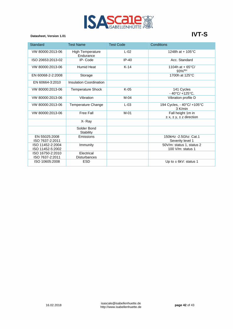
Standard Test Name Test Code Conditions
VW 80000:2013-06 High Temperature Endurance
L-02 1248h at + 105°C
ISO 20653:2013-02 IP- Code IP-40 Acc. Standard
VW 80000:2013-06 Humid Heat K-14 1104h at + 65°C/ 93%RH
EN 60068-2-2:2008 Storage 1700h at 125°C
EN 60664-3:2010 Insulation Coordination
VW 80000:2013-06 Temperature Shock K-05 141 Cycles - 40°C/ +125°C,
VW 80000:2013-06 Vibration M-04 Vibration profile D
VW 80000:2013-06 Temperature Change L-03 194 Cycles, - 40°C/ +105°C 3 K/min
VW 80000:2013-06 Free Fall M-01 Fall height 1m in ± x, ± y, ± z direction
X- Ray
Solder Bond Stability
EN 55025:2008 ISO 7637-2:2011
Emissions 150kHz -2.5Ghz: Cat.1 Severity level 1
ISO 11452-2:2004 ISO 11452-5:2002
Immunity 50V/m: status 1, status 2 100 V/m: status 1
ISO 16750-2:2010 ISO 7637-2:2011
Electrical Disturbances
ISO 10605:2008 ESD Up to ± 6kV: status 1

Datasheet, Version 1.01 IVT-S
16.02.2018 [email protected] http://www.isabellenhuette.de
page 43 of 43
11. Index
Figure 1 CAN-bus 6 Figure 2 averaging over 5 ms 6 Figure 3 ADC channel 1 and 2 6 Figure 4 example with two channel on ADC2 7 Figure 5 example with three channel on ADC2 7 Figure 6 Configuration: 1 current channel, 3 voltage channel, 3 ms measurement interval 8 Figure 7 Configuration: 1 current channel, 2 voltage channel 8 Figure 8 two channels; 5 ms output rate 9 Figure 9 four channels; 6 ms output rate 9 Figure 10 four channels; different measure interval 9 Figure 11 Example for voltage measurement 11 Figure 12 IVT-S 1000A and 2500A version 14 Figure 13 correct mounting 20mm overlap 15 Figure 14 Incorrect mounting 15mm overlap 15 Figure 15 correct mounting 20mm overlap 15 Figure 16 Incorrect mounting 15mm overlap 15
1. Introduction ................................................................................................................................. 1 2. Application .................................................................................................................................. 1 3. Functionality description ............................................................................................................. 2
3.1. Measurement modes ............................................................................................................................ 2 3.2. Output signals ....................................................................................................................................... 2 3.3. Internal Safety ...................................................................................................................................... 3 3.4. Log data ............................................................................................................................................... 3 3.5. Firmware update ................................................................................................................................... 4 3.6. Galvanic isolation ................................................................................................................................. 4 3.7. Communication interface ...................................................................................................................... 4
4. Measurement description ........................................................................................................... 6 4.1. Sampling rates ...................................................................................................................................... 6 4.2. Overcurrent measurement .................................................................................................................. 10 4.3. Temperature calibration ...................................................................................................................... 10 4.4. Ranges ............................................................................................................................................... 10 4.5. Plausibility check (functional safety) ................................................................................................... 11 4.6. Voltage measurement ........................................................................................................................ 11
5. Technical Data .......................................................................................................................... 12 5.1. Operation conditions ........................................................................................................................... 12 5.2. Maximum Rating ................................................................................................................................. 12 5.3. Current measurement ......................................................................................................................... 12 5.4. Voltage measurement ........................................................................................................................ 13 5.5. Communication ................................................................................................................................... 13
6. Mechanical Data ....................................................................................................................... 14 6.1. Busbar connection .............................................................................................................................. 15 6.2. Pin configuration / Power Supply and CANbus................................................................................... 16 6.3. Pin configuration / Voltage measurement ........................................................................................... 16 6.4. Module Connector .............................................................................................................................. 17 6.5. Mating plug ......................................................................................................................................... 17
7. Part description / Ordering........................................................................................................ 18 8. CANbus protocol ...................................................................................................................... 19
8.1. Result messages ................................................................................................................................ 21 8.2. Set CAN ID ......................................................................................................................................... 23 8.3. Config Result ...................................................................................................................................... 23 8.4. Set-Commands ................................................................................................................................... 24 8.5. Get Error- and Logdata ....................................................................................................................... 27
9. Startup ...................................................................................................................................... 40 10. Qualification .............................................................................................................................. 41 11. Index ......................................................................................................................................... 43