Advanced security made easy PC-DVR4-Net - Swann
28
SW231PC4 & SW231-UD4 www.swannsecurity.com xxxxx-xxxxx-xxxxx-xxxxxxxx Operating Instructions ™ ™ Advanced security made easy PC-DVR4-Net Operating Instructions Software Version 6.3.0.7 SW241-PC4™ SW241-UD4™
Transcript of Advanced security made easy PC-DVR4-Net - Swann

SW231PC4 & SW231-UD4www.swannsecurity.com xxxxx-xxxxx-xxxxx-xxxxxxxx
Operating Instructions
™
™Advanced security made easy
PC-DVR4-Net
Operating InstructionsSoftware Version 6.3.0.7
SW241-PC4™
SW241-UD4™

2
Before you BeginFCC Verification:NOTE: This equipment has been tested and found to comply with the limits for Class B digital device, pursuant to part 15 of the FCC Rules. These limits are designed to provide reasonable protection against harmful interference in a residential installation. This equipment generates, uses and can radiate radio frequency energy and, if not installed and used in accordance with the instructions, may cause harmful interference to radio or television reception, which can be determined by turning the equipment off and on, the user is encouraged to try to correct the interference by one or more of the following measures:· Reorient or relocate the receiving antenna· Increase the separation between the equipment and the receiver· Connect the equipment into an outlet on a circuit different from that to which the receiver is connected· Consult the dealer or an experienced radio/TV technician for help
These devices comply with part 15 of the FCC Rules. Operation is subject to the following two conditions: (1) These devices may not cause harmful interference, and (2) These devices must accept any interference received, including interference that may cause undesired operation.
IMPORTANT NOTE: Prohibition against eavesdroppingExcept for the operations of law enforcement officers conducted under lawful authority, no person shall use, either directly or indirectly, a device operated pursuant to the provisions of this Part for the purpose of overhearing or recording the private conversations of others unless such use is authorized by all of the parties engaging in the conversation.
WARNING: Modifications not approved by the party responsible for compliance could void user’s au-thority to operate the equipment.
IMPORTANT SAFETY INSTRUCTIONS: · Make sure product is fixed correctly and stable if fastened in place· Do not operate if wires and terminals are exposed· Do not cover vents on the side or back of the DVR and allow adequate space for ventilation
DEFAULT PASSWORD INFORMATION
The username for the default account for the PC-DVR “SYSTEM”. The password in blank (i.e. enter nothing). This is an administrator account, and will allow anything in the configuration of the DVR to
be changed. We strongly suggest changing this as soon as possible.

3
Table of ContentsBefore you Begin 2Table of Contents 3
Overview 4Layout PCI Version 5 USB Version 5Installation Hardware 6 Software 7
Main Interface 8Basic Configuration 9Recording 10Video ProcAmp 11Motion Detection 12Schedule 13Alarm / Sensor Configuration 14Auto-Mail 16P.T.Z. (Pan, Tilt, Zoom) Configuration 16P.T.Z. (Pan, Tilt, Zoom) Control 17User Configuration 17Playback 18Capture and Backup 19
Networking the PC-DVR 20Remote Access 21The Remote Viewing Interface 22The Remote Playback Interface 23Remote Configuration 24Connecting via iPhone 25Troubleshooting Guide 26Technical Specifications 27Helpdesk / Technical Support Rear CoverWarranty Information Rear Cover

Overview
4
Congratulations on your purchase of this Swann four channel PC-based surveillance system. You’ve chosen an extremely cost effective and adaptable security solution to integrate with your existing computer system.
The PC-DVR and included software will allow you to turn your computer into a fully featured digital video recorder with advanced networking and remote access features. You’ll be able to monitor four cameras at a time, and record footage directly to your computer’s hard drive.
Whether you have the external USB PC-DVR or the internal PCI card version of the PC-DVR, this manual will cover everything from installing your hardware to configuring your system for remote viewing (that is, being able to access your security system via the Internet).
The PC-DVR boasts the following features:
Advanced video compression: The PV-DVR records footage using the powerful MPEG-4 compression, allowing for high-quality footage requiring the minimum possible hard drive space. This is the same format used by Blu-Ray discs to store high definition video and a favorite format for Internet video due to its high quality and small file size.
Flexible Recording Options: The PC-DVR can be configured to operate using several different recording modes. You can record constantly (Manual Recording), record based on a schedule (Schedule Recording) or record only when something happens in view of one of your cameras (Motion Detection Recording) or automatically record when one of your alarms are triggered (Sensor Alarm Recording).
Support for Pan, Tilt and Zoom cameras: Supporting a number of PTZ control decoders, the PC-DVR is compatible with many different PTZ (pan, tilt, zoom) control systems and can be configured to control multiple stand-alone or dome-mounted camera systems simultaneously.
Real-time, multi-camera displays: There are numerous viewing methods available using the included software, including split screen and automatic channel cycling.
Multiple Recording Search Options: Search for recordings using the time and date they were recorded, the camera they were recorded on, the recording mode in which they were recorded, or a combination of these criteria.
Remote Access and Networking Features: Being directly incorporated into your PC, the PC-DVR is highly network compatible. You can monitor live images and engage playback via both the local area network and remotely via the Internet once properly configured. It also allows for the remote control of PTZ compatible camera systems.
System Requirements Minimum RecommendedCPU: Intel PIII 800MHz or equivalent Intel PIV 1GHz (or equivalent) or higherMemory: 256MB 512MB or moreVideo RAM: 32MB 64MB or higherNetwork Card: 10/100Mbps or faster 10/100Mbps or fasterOperating System: Microsoft® Windows® XP Microsoft® Windows® Vista 32-bit Microsoft® Windows® 7 32-bit (PCI Version ONLY)Direct Draw: Microsoft® DirectX® 9.0If your computer does not meet the minumum system requirements, we recommend not installing the PC-DVR on this system. Consider upgrading your computer system, or acquiring a new PC to use the PC-DVR.
Please note that whilst multiple PCI PC-DVR cards can be installed into one computer system, the USB version of the PC-DVR does not support this feature.
Additionally, the USB and PCI versions of the PC-DVR cannot be used in conjunction.

Layout: PCI Card Version
Layout: USB Version
5
Rear of CardCamera Connections
1 2 3 4
1
2
3
4
BNC Plugs for Cameras
Alarm Port
Data Connectors
(PCI)
BNC Plugs for Cameras
Alarm Port
Data Connectors (PCI)
USB Plug for connection to PC
Audio RCA Plugs (for Microphone or other
sound device)
Video RCA Plugs (for Camera)

6
Installation: HardwareInstalling the PC-DVR: PCI Card Version
Installing the PC-DVR: USB Version
2. Remove the cover from your computer case. Exercise caution whilst doing so - some components can retain an electrical charge even once the power has been disconnected.
Remove the screws 1. holding your computer’s cover in place.
Locate a spare USB 2.0 port on your computer. Avoid using a hub, USB extension lead or USB 1.0 or 1.1 ports, as these 1. will limit the bandwidth available to the DVR, causing the unit to perform poorly or not at all.Plug the USB plug on the PC-DVR into the spare USB 2.0 port. Your operating system will detect it automatically, and ask 2. you if you want to install drivers. Be sure to choose “NO” - the drivers will be installed along with the software during the next step of installation.
7. Replace the cover of your computer, replacing screws as necessary, and reattach any cables disconnected during the installation procedure.
8. Start your computer.
5. If necessary, remove the spare slot cover. Often, these are screwed in place, but sometimes are physically part of your computer’s case, perforated for easy re-moval. In the latter circumstance, exercise care when removing the slot cover – the perforated edges can be sharp!
6. Carefully insert the PC-DVR card into the spare PCI slot. Grip the card at both ends, and apply even, steady pressure until it is firmly and completely inserted into the PCI slot. Insert and fully tighten a screw into the thread located on top of the slot cover.
4. Locate a spare PCI slot. Generally, these are located on the motherboard of your computer and are white.
3. With care, lay your computer down on it’s side so that the internal components (i.e. the motherboard and PCI cards) are facing upright.
IMPORTANTRead before you attempt installation:Be aware that you may void the •manufacturer’s warranty by opening your computer case. If in doubt, contact your retailer for more information before proceeding.To avoid static discharge to sensitive parts, •wear rubber soled shoes. Grip the metal of the case momentarily to discharge any static electricity before going any further.If you are unfamiliar with installing and/•or maintaining computer hardware, we suggest employing the services of a professional computer technician to install the PCI card into your computer.
7
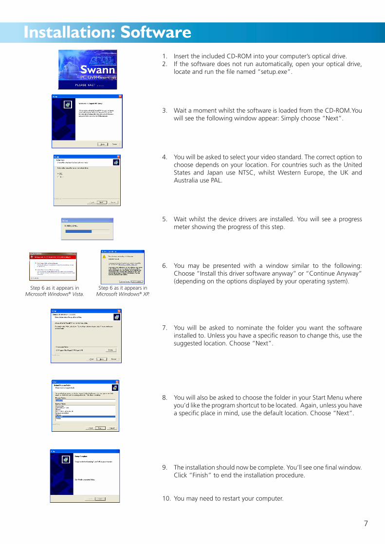
Installation: Software1. Insert the included CD-ROM into your computer’s optical drive.2. If the software does not run automatically, open your optical drive,
locate and run the file named “setup.exe”.
3. Wait a moment whilst the software is loaded from the CD-ROM.You will see the following window appear: Simply choose “Next”.
4. You will be asked to select your video standard. The correct option to choose depends on your location. For countries such as the United States and Japan use NTSC, whilst Western Europe, the UK and Australia use PAL.
5. Wait whilst the device drivers are installed. You will see a progress meter showing the progress of this step.
6. You may be presented with a window similar to the following: Choose “Install this driver software anyway” or “Continue Anyway” (depending on the options displayed by your operating system).
7. You will be asked to nominate the folder you want the software installed to. Unless you have a specific reason to change this, use the suggested location. Choose “Next”.
8. You will also be asked to choose the folder in your Start Menu where you’d like the program shortcut to be located. Again, unless you have a specific place in mind, use the default location. Choose “Next”.
9. The installation should now be complete. You’ll see one final window. Click “Finish” to end the installation procedure.
10. You may need to restart your computer.
Step 6 as it appears in Microsoft Windows® Vista.
Step 6 as it appears in Microsoft Windows® XP.

Main Interface
Please Note: The above example shows the maximum number of images that the software can display. If you have the PCI version of the PC-DVR and additional free PCI slots, additional cards can be added to your system - up to a maximum of four cards allowing for 16 channels.
Only ONE (1) USB PC-DVR can be connected to a computer at a time. The USB version cannot be used in conjunction with the PCI version of the PC-DVR.Using multiple PCI PC-DVR cards simultaneously is an advanced feature of the unit,
and not recommended for novice users.
Default state
Manual Recording Mode
Schedule Recording Mode
Motion Detection Recording Mode
Sensor/Alarm Recording Mode
Each light on the Channel Status display corresponds to one camera connection. The color of the light indicates the current status of that channel.
8
1/CAM1•
• 3/CAM3
• 2/CAM2
• 4/CAM4
Live Viewing Display
EMAP
Lock / Unlock
Event Search
Configuration Panel
PTZ Controls
Exit Button
Time & Date
Remaining Hard Drive
Space Indicator
Viewing Mode
Switches
Capture UrgentRecord
SingleView
Channel Status
QuadView
Auto-Cycle

Auto-Cycle Config: When Auto-Cycle display mode is engaged (that is, the PC-DVR displays one channel at a time, automatically cycling through all active channels) these settings will determine how long it dwells on each channel.Dwell Time: How long each channel will be displayed for.Caption: Choose how each channel will be identified. None: No title will be shown. ID: Will display the camera’s number. Name: Will show the name tagged on that camera. ID/Name: Will show the name and ID of that camera.Live Audio: Change which audio channel will be recorded.Audio Config: Here you can change the GAIN (essentially the volume) of one or both audio channels.
Networking Configuration: Here you can choose the port settings that the PC-DVR uses to interface with your LAN and the Internet.
Storage Location: Lets you choose which hard drive the software will record data to. Only drives already connected to your system will appear here.
Auto-Reboot & Auto-Login Configuration Tab: Click here to access the Auto-Reboot and Auto-Login Configuration tabs.
Basic Configuration: The current screen. From other configuration windows, this will take you back to this screen.
Schedule Configuration: Opens the schedule window. If you want the PC-DVR to record at certain specific times, this is where you can program that schedule.Video Configuration: Opens the video configuration window, where you can change the size and quality of the video files the software will save.
Motion Detection Configuration: If you want the PC-DVR to record when movement occurs within view of the cameras, use this screen to configure the motion detection settings.
Alarm Configuration: If you have an external alarm system connected to the PC-DVR, then this is where you’ll be able to define which channels record on which alarm signal.P.T.Z. Configuration: For remotely controlling the pan, tilt and zoom features of a P.T.Z. capable camera system.
User Configuration: Where you are able to configure other settings not covered in the other menus.
Channel Attributes: Where the individual attributes associated with each channel can be changed and modified. See overleaf for details.
Auto-Reboot Configuration: As computers need to be occasionally rebooted to ensure they continue to operate reliably, the PC-DVR software includes the option to do this automatically. Select the frequency of rebooting here.
Auto-Login Configuration: Used primarily in conjunction with the auto-reboot feature. You can input the username and password you use to login to Windows here, and the PC-DVR will automatically login to Windows when the computer restarts.
Access the Basic Configuration screen by clicking on the Configuration Panel icon (the one that looks like a spanner). Here, you can configure and control various aspects of the PC-DVR’s functionality. In addition, the Configuration Menu located on the right hand side of this window contains the links to the recording option setup screens.
Basically, if you want to make the PC-DVR function differently from the default settings, this is where you do it.
Basic Configuration
Auto-Reboot Configuration
Auto-Login Configuration
Storage Location Network ConfigurationAuto-Reboot & Auto-Login Config Tab
Auto-Cycle Config
Basic Configuration
Schedule Configuration
Video Configuration
Motion Detection Config
Alarm Configuration
P.T.Z. Configuration
User Configuration
Return to Live Viewing ModeRecord Setup
9

10
Recording
Time Stamp: Will print the time and date to the corner of the footage captured on this channel. Very useful if you’re planning on using any of the footage from that channel to prove that a certain event happened at that time.
Switch: Turns channels ON or OFF. If, for example, you have a single four-channel PC-DVR connected to your computer but only three cameras attached, turn off the additional channel to save on system resources.
Record Mode / Frame Rate: Shows the associated recording modes and frame rates for each channel. A tick in the box means that the channel is configured to record in that mode, whilst the frame rate indicates how many images per second will be captured by that channel when triggered by that
recording mode. Where multiple recording modes are active simultaneously, the highest frame rate will be used up to a global frame rate (that is, all channels frame rates added together) of 25fps.
Camera Security: You can set various levels of security for different channels - only users with that level of access or higher will be able to view said channels. There are three levels of security access available: Normal User, Power User and Administrator.
Record Quality: Changes the ‘bit-rate’ of the recorded video files. A higher quality setting means the video is using a higher bit-rate, leading to better looking images with more detail in them. Higher quality videos use more hard drive space than lower quality ones.
The PC-DVR has four recording modes:Manual Recording•Scheduled Recording•Motion Detection based Recording•Alarm (Sensor) Recording•
Manual Recording will record everything from the selected channels until manually stopped. Though it seems that manual recording may be a popular recording mode, it is not: constant recording uses too much hard drive space too quickly to be practical for most applications.
Scheduled Recording will have the PC-DVR recording only at certain times of the day. This is a good option for monitoring a busy street outside your home/business overnight, or in other situations where motion or alarm based recording is impractical, without the full hard drive usage of manual recording mode.
Motion Detection based Recording will trigger the PC-DVR to record a channel whenever something is actively moving in view of the camera. The sensitivity of the motion detection can be configured, in addition the area in the picture where the PC-DVR looks for motion can be defined. The combination of specific motion detection criteria and reduced hard drive usage makes motion detection one of the most popular and successful recording modes available. However, the sensitivity and motion detection area must be set correctly and with care for the system to function properly.
Alarm (Sensor) Recording: For those with the PCI version of the PC-DVR (the USB version does not have alarm inputs). If you have an external alarm system, this can be connected to the PC-DVR to trigger recordings. Attaching an external alarm to the PCI version of the PC-DVR is an advanced feature of the unit, and recommended for intermediate to advanced users only.
You can assign recording modes to individual channels via the Record Setup Table, located in the Basic Configuration screen.
Tips and Tricks: Multiple Recording Modes
You can assign one recording mode to a channel easily enough - but there’s no reason to stop there.
Multiple recording modes can be employed on the same channel simultaneously. For example, you could record from 9am to 10am every day, and also whenever the PC-DVR detects motion.
In addition, you can select different frame rates for each recording mode. This means that you could, for example, record a very low number of frames constantly, and then increase the frame rate upon an alarm being triggered.

11
Video ProcAmpChannel Select Menu
Video PreviewVideo AdjustmentsThe Video ProcAmp (an acronym for
“Processing Amplifier”) page will allow you to customize the look of each channel.
The adjustable settings here will not change the recording quality or frame rate of the video files.
You can use the Video Adjustments to fine tune the images coming from each channel. For example, you can adjust the brightness and contrast of an image to more easily distinguish details.
You can also manually tweak settings such as the gain (normally set to ‘auto’) allowing you to compensate for a ‘backlit’ image where the background is too bight and the subject too dark.
Channel Select Menu: Choose the appropriate channel that you would like to adjust here.
Video Preview: The current image from the selected channel. You can monitor the changes to the appearance of the video in real-time here.
Video Adjustments: The nitty-gritty of the Video Configuration menu. When adjusting these settings, remember that they affect one another quite dramatically - for example, setting the Contrast alone will not produce results as desirable as using the Contrast and Brightness settings in conjunction with one another. A little experimentation is often the best way to find the right solution for you. If anything ever gets out of hand whilst experimenting with these settings, you can use the ‘Defaults’ button to return all values to their starting position.
Contrast: Changes the relative brightness between the darkest and lightest points in the channel’s image. Adjusting the contrast is a good idea if sections of the image are “greying out” as adjusting the contrast will make subtle details more apparent. However, setting the contrast too high will exaggerate ‘artifacts’ in the video. (An ‘artifact’ is digital distortion caused by the compression of the video file. Artifacts usually show up as slightly mis-colored rectangles in your images.
On the other hand, lowering the contrast will make the relative brightness values of the light and dark spots in the image less dynamic. Slightly lowering the contrast will improve the aesthetics of the image, and cover up any apparent video compression artifacts.
Brightness: Makes everything in the image brighter or darker. Adjusting the brightness is a good idea if you have an unusually bright or dark monitor, or are viewing the monitor in a particularly bright/dark location.
If the camera connected to the channel that you’re adjusting
the brightness for is not getting enough light to create a dynamic image and appears black, adjusting the brightness will not make details in the image visible but merely make the black appear grey (or even white). Adjust the contrast and gain as well.
Hue: Changes the color mix in the image, often with very dramatic results. If your camera system is not giving an accurate representation of color in the image, which can often happen if your cameras have infrared night vision, you can try correcting it by adjusting the hue. Be aware that small changes to the hue value will give dramatic results. Also, there may not be a position on the slider which corrects all color imperfections in your image, but with a little experimentation you should be able to find a value which improves the video coloring somewhat.
Saturation: The amount of color in the image. Using less saturation will lead to a ‘washed out’ image, whilst reducing it to zero will give you a black & white image. Increasing the saturation will give more bright and vibrant colors - however, setting the saturation too high will degrade video quality and exaggerate any imperfection in your camera’s color representation.
Gain (Auto/Manual): The gain is the amount of amplification applied to the camera’s signal in order to generate the video image. Normally, this will be set to ‘Automatic’ in order to deal with changing light conditions - for example, the sun rising and setting. However, if the auto setting does not work for your setup, find the manual setting which works for you. Remember that once set to manual, the PC-DVR will not adjust exposure levels, even if the image blacks out (under exposes) or whites out (over exposes).
Defaults: Returns all values to their initial positions. The Contrast, Brightness, Hue and Saturation will revert to 5000 (half way along the slider, between 0 and 9, 999) whilst the Gain will return to Auto, with the slider located at 0.

12
Motion DetectionFor most uses of the PC-DVR, correctly configured Motion Detection based recording is the most efficient, convenient and viable recording option on a long term basis.
For motion detection to function properly, there are a few key settings which we have to ensure are set correctly - in order to access these settings, use the Motion Detection Configuration window.
It is recommended that systems which employ P.T.Z. cameras do not use Motion Detection based recording, as movement of the camera will trigger the DVR to record. See “How Motion Detection Works” below for more information.
Channel Selection Menu: Choose the channel that you would like to alter the motion detection setting on here.
Sensitivity Settings: How much movement the PC-DVR needs to ‘see’ before it activates the motion-based recording, and where it will and will not be detected can be customised.
Sensitivity: High sensitivity values will require less motion to trigger the PC-DVR to record. Lower sensitivity values will need more movement to trigger recording - extremely low values (such as < 5) will rarely - if ever - trigger recordings, whilst values upwards of 95 will give many ‘false alarms’.
Motion Area Display: You can alter which parts of the channel will be motion sensitive here by clicking and dragging on an area with the mouse to create a new motion detection area (it helps to use the Clear button first - see below).
You can define up to 16 separate motion sensitive areas. These are marked by green boxes, which will appear as you click and drag the mouse over the area in question. Motion occurring outside these defined spaces will not trigger the PC-DVR to begin recording.
Select All/Clear: You can use these buttons to quickly set the whole channel area to be motion sensitive (Select All), or remove all defined motion sensitive areas (Clear). Be careful not to accidently click these buttons once you’ve defined your custom motion detection area, as you’ll have to define it all over again!
To correctly set the Motion Detection sensitivity:
You’ll need the help of an able-bodied assistant to play the part of pretend security risk.
Whilst you are monitoring the Motion Detection Configuration screen on your PC-DVR, get your assistant to move through the camera’s view in much the same way as a real security risk would - moving at a regular walking pace, and not trying
to be noticed.You’ll see small, green, circular markers appear on the screen where the PC-DVR is detecting motion. Whilst your assistant is in front of the camera, adjust the sensitivity setting until your assistant (and only your assistant) is registered as motion. Make a note of this point. Then, lower the sensitivity until your assistant doesn’t register as motion, and note this point. Somewhere close to halfway between these points is an ideal setting for your motion detection sensitivity, as it should reliably detect the motion of a human without producing many false alarms.
If necessary, you may need to adjust the motion detection area. This is often the case if (for example) a busy road or tree that blows in the wind is in view of your camera. Simply define the areas that are normally still that a security risk would have to move through.
How Motion Detection Works:
The image that the PC-DVR ‘sees’ (i.e. the image that it displays to you) is made up of thousands of tiny dots called pixels. As a general average, there are somewhere in the order of half a million pixels per ‘frame’ of video footage. A ‘frame’ is a still image. If you play enough of them close together, they give the illusion of a single moving image. The PC-DVR will display 25 to 30 frames per second.
When the PC-DVR looks for ‘motion’, what it is really doing is comparing each frame with the preceding one, and counting how many pixels “change”. This change could be the pixel becoming lighter or darker, or changing color, or both.
Bear this in mind when setting up your motion detection, as things like changing lighting conditions (such as the sun being temporarily obscured by clouds, or someone turning a light on or off) as well as moving or bumping the camera can trigger the PC-DVR to record. Also, bear in mind that motion detection is a process executed by the PC-DVR, not your cameras.
Channel Selection MenuMotion Area Display
Sensitivity Settings
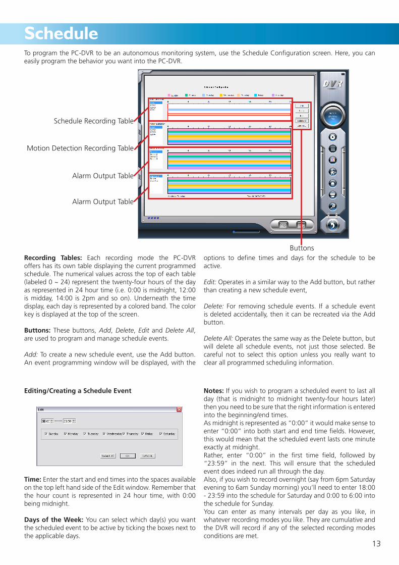
Editing/Creating a Schedule Event
Time: Enter the start and end times into the spaces available on the top left hand side of the Edit window. Remember that the hour count is represented in 24 hour time, with 0:00 being midnight.
Days of the Week: You can select which day(s) you want the scheduled event to be active by ticking the boxes next to the applicable days.
Notes: If you wish to program a scheduled event to last all day (that is midnight to midnight twenty-four hours later) then you need to be sure that the right information is entered into the beginning/end times.As midnight is represented as “0:00” it would make sense to enter “0:00” into both start and end time fields. However, this would mean that the scheduled event lasts one minute exactly at midnight.Rather, enter “0:00” in the first time field, followed by “23:59” in the next. This will ensure that the scheduled event does indeed run all through the day.Also, if you wish to record overnight (say from 6pm Saturday evening to 6am Sunday morning) you’ll need to enter 18:00 - 23:59 into the schedule for Saturday and 0:00 to 6:00 into the schedule for Sunday.You can enter as many intervals per day as you like, in whatever recording modes you like. They are cumulative and the DVR will record if any of the selected recording modes conditions are met.
13
ScheduleTo program the PC-DVR to be an autonomous monitoring system, use the Schedule Configuration screen. Here, you can easily program the behavior you want into the PC-DVR.
Recording Tables: Each recording mode the PC-DVR offers has its own table displaying the current programmed schedule. The numerical values across the top of each table (labeled 0 ~ 24) represent the twenty-four hours of the day as represented in 24 hour time (i.e. 0:00 is midnight, 12:00 is midday, 14:00 is 2pm and so on). Underneath the time display, each day is represented by a colored band. The color key is displayed at the top of the screen.
Buttons: These buttons, Add, Delete, Edit and Delete All, are used to program and manage schedule events.
Add: To create a new schedule event, use the Add button. An event programming window will be displayed, with the
options to define times and days for the schedule to be active.
Edit: Operates in a similar way to the Add button, but rather than creating a new schedule event,
Delete: For removing schedule events. If a schedule event is deleted accidentally, then it can be recreated via the Add button.
Delete All: Operates the same way as the Delete button, but will delete all schedule events, not just those selected. Be careful not to select this option unless you really want to clear all programmed scheduling information.
Buttons
Schedule Recording Table
Motion Detection Recording Table
Alarm Output Table
Alarm Output Table

Alarm / Sensor Configuration
14
Left: The EMAP configuration window. Here you can choose how long you’d like the map to be displayed for during an alarm event. This is also where you access the EMAP definition screen, shown to the right.
Right: The EMAP definition screen. This is where you’ll be able to import a map of your home or office, and place your cameras on this map. You can define up to eight maps - this is useful for large or multi-story buildings, or for representing a separate area of surveillance, like a car park.
Events monitored by the PC-DVR (such as detecting motion or losing a video signal) can trigger an alarm.
The alarm is typically sound based, and generated by the PC that the card is installed in (and thus produced by the same speaker system attached to the computer).
There is also the option of routing the alarm signal to an external device via the alarm output port. This is an advanced feature of the DVR, and something we suggest only those with experience building and maintaining computer systems attempt.
For most purposes - should remote notification of alarm events be required - we suggest that the Auto-Mail feature is more applicable.
Buzzer: Turns the auditory alarm emitted by the PC with the PC-DVR attached on and off. Without the buzzer (or the Remote Alarm) turned on, only an dialog box on the PC screen will alert you to an alarm event occurring.
Motion Holding Time: The amount of time an alarm will last after detecting a motion event. The alarm will occur continuously whilst motion is occurring - the Motion Holding Time will determine how long the alarm will continue for after the motion event has ended.
Sensor Holding Time: Works in a very similar way to the Motion Holding Time - the primary difference is that this setting determines how long an alarm event lasts after the external sensors cease triggering the PC-DVR.
Disk Shortage Alarm: Will cause an alarm event when the hard drive(s) used to record footage to are about to run out of space. If you have the Recycle function turned on, then this alarm is not as important, as the PC-DVR will automatically delete old footage to ensure there is always space for new events to be recorded.
Alarm Out 1: You can turn the remote alarm setting on and off here.
The EMAP function allows you to import a map or plan of your home or office. You can then place icons which represent your cameras on the EMAP, effectively creating a very user-friendly map of your immediate environment and the cameras therein.
In the event of an alarm event, the EMAP will be displayed for a short time, indicating exactly where the alarm event has been detected (turn this feature ON or OFF using the EMAP button on the main interface, and checking or unchecking the “Auto Show” box).
If you want to use an Emap, first you’ll need to create or load a map of your environment, saving it as either a .BMP or .JPG file.
Importing your EMAP: Click EMAP edit. •Once you’ve opened the EMAP, select a map number •from the list on the left. Then, right-click on the default map image and choose •“Load Picture”.To defining your camera placement, simply grab a •camera from the device list on the upper left-hand side of the display. Then, drag it onto the Emap, and place it as appropriate.Right click and choose “Save” to retain your Emap.•

Auto-Mail
If you’re often away from the PC-DVR but want to be immediately alerted when an alarm event occurs, you can use the Auto-mail function. When an alarm event occurs, the PC-DVR will generate and send an email to your specified address informing you of the time, date and nature of alarm events as they occur.
For this function to work correctly, Auto-mail must be enabled and correctly configured, and the PC containing the PC-DVR must be connected to a network with Internet access.
NOTE: As the emails sent by the PC-DVR are generated procedurally, many outgoing mail servers misinterpret the email and the automatic generation technique used as being spam. As a result, the spam filtering system which most mail servers now offer will block the mail being sent. We recommend finding a mail server which does not interpret the PC-DVR’s emails as spam. At the time of writing, G-Mail (www.gmail.com) offers a free email account which does work with the PC-DVRs emailing system. Remember that the majority of web-based mail servers will require SMTP protocol to be enabled before external devices and programs will be able to send mail from that account.
If ANY settings are incorrect, the Auto-mail will not work and NO EMAIL WILL BE SENT.We suggest testing the setup extensively before relying on it!
Mail Server Setup: The PC-DVR requires a compatible SMTP mail server configured here to send email. This is NOT the email address that the alert will be sent to, but rather the email server being used to send the message.
SMTP Server: Here is where you define your outgoing mail server. The server being used must support the SMTP outgoing mail protocol. Additionally, test your outgoing mail server before relying on the Auto-mail feature, as the email generated by the PC-DVR is often misinterpreted as spam and stopped by the mail server’s spam filter.Note that the first part of the mail server’s Internet address (the URL) may not start with “www”, even if that’s the address you use to get to the webmail interface. Typically, outgoing mail server addresses start with prefixes such as “mail” or “SMTP”.
E_Mail From: This is where you enter your outgoing mail address. Typically, this is YourUsername@YourServer (eg. [email protected]).
Username & Password: The username and password for your outgoing mail server. These are used for identity verification, preventing unauthorized persons sending mail from your email account. Check whether this is necessary with your email provider.
Mail Setup: Here you enter the details of the email address you want to send the Auto-mail to.
Send To: Your (or the intended recipient of the Auto-mail) email address.
Subject: What you want to appear in the subject line of the email being sent.
Test Message Body: When sending a test message, what you enter into this field will appear in the body of the test email.
Attachment Setup: When an Auto-mail message is sent, you can choose what additional information accompanies it.
Camera: Choose whether or not you would like an image from the camera which triggered the alert to be attached to the email.
Time: Choose whether the time and date of the alarm event is contained in the attachment to the Auto-mail.
Format: What file type the attachment is. JPG is the typical default, as it reduces file size whilst retaining most perceptible details.
Resolution: How big the attached image file will be. Larger images provide more details, but are larger and take longer to send/receive. This is becoming less of an issue as Internet
15

P.T.Z. (Pan, Tilt, Zoom) ConfigurationIf you are using a PTZ capable camera/dome system, you can use the PC-DVR to control the PTZ capabilities of your camera via one of your computer’s COM ports.
Configuring a PTZ system can be a bit tricky, so make sure you have the documentation for your PTZ system handy when setting up the PC-DVR - there’ll be some settings you’ll need to get exactly right!
Please note that whilst the PC-DVR has a full compliment of PTZ controls, the actual capabilities of your system will be determined by the limitations of your camera/dome system. Commands which your PTZ system cannot execute will have no effect on your PTZ system.
Port: Choose the port on your computer that you would like to attach the RS485 command wires to. You can choose any communication port (COM port) on your computer system, control multiple PTZ systems from one COM port or use multiple COM ports to control one or multiple cameras simultaneously.
Many computers produced in recent years have lacked COM ports - the uptake of USB and wireless technologies have reduced the appeal of them, particularly in systems intended for home or office use. However, there are a number of possible solutions, a common one being to purchase a PCI expansion card for your computer, which is installed in the same manner as the PCI version of this DVR. These are quite inexpensive, but do require some knowledge of computer hardware to install correctly. Of course, it’s no more difficult than installing the PCI version of the PC-DVR/
Address: Here, enter the command address of the camera system you want to control in association with the selected channel. To learn/define your PTZ system’s command address, consult your PTZ system documentation. (Typically, there are a series of DIP switches located somewhere on the command board.)
Protocol: Choose the protocol as listed in your PTZ system documentation. Choosing any other protocol will result in the PTZ system performing poorly, or not at all.
Baud Rate: Refers to the speed at which command data will be sent to the PTZ system. It is important to match this setting with your PTZ system. Some systems are not so fussy about their baud rate, and will accept any value up to their maximum speed. Others, however, are quite temperamental, and will not function unless the baud rate is exactly right. This information, much like the other settings you will configure here, can be found in your PTZ system’s documentation.
Bit Settings: Information sent to the PTZ system comes in small blocks, a predetermined number of bits long with specific codes for determining the border between packets and error checking. The length of the data bit string, as well as the parity is typically determined by your protocol. However, the setting can be tweaked here.
Data Bits: The main information contained in the command packet are arranged into a string called ‘Data Bits’. The length varies, but for most systems is between 8 and 24.
Parity Bit: A form of error checking, which reduces the chances of miscommunication between the PC-DVR and attached PTZ system.
Stop Bit: How many bits are used to indicate the end of a packet. Typically, the value is “1” or “2” - however, some protocols with more or no Stop Bits exist.
Note: These settings will automatically be set to their defaults for your chosen protocol. Only alter the values here if the protocol defaults do not work correctly.
16

This is the control panel displayed for controlling PTZ capable camera systems via the PC-DVR.
Arrow Buttons: These directional buttons will pan and tilt the camera when pressed. Their direction is relative to the aim of the camera, not absolute (i.e. the left button will always pan the camera left relative to its view, rather than making the camera point left relative to an observer). Clicking the arrow once will cause the PTZ system to continue panning/tilting until the stop button is pressed.
Stop Button: Will stop the PTZ system from moving. Use this to stop the camera panning/tilting after one of the arrow buttons has been used.
Focus: Moves the area of the image which is in focus (also called “Depth of Field”). Use this control to find focus on objects or scenes which appear to be blurry. If adjusting the focus has no effect on the sharpness of your image, then it may be the case that your camera’s lens needs cleaning. Many entry-level PTZ systems lack a manual focus option, and will find focus automatically.
The depth of field (the amount of the image which is in focus) will decrease as you zoom in, and increase as you zoom out. Also, focus is easier to find when there is a lot of light.
Zoom: Controls the magnification of the image. Zooming in will make everything in the image bigger, but will reduce the field of vision accordingly.
Exposure (Iris): Controls how much light gets into camera. An open iris lets in lots of light, whilst a closed iris lets in only a little bit of light. If large sections of your picture are bright white (over-exposed) or pitch black (under-exposed) then adjust the exposure to compensate. Much like the manual focusing controls, many entry-level PTZ systems will not have a manual iris control (or, indeed, an iris at all). In these cases, exposure adjustment is usually automatic, and done electronically by changing the sensitivity of the image sensor (commonly called adjusting the ‘gain’).
User ConfigurationIt may be the case that you wish to control who has access to the information on your PC recorded or being monitored by the PC-DVR. You may want certain users to have access to all aspects of the PC-DVR’s operation, whilst others would be restricted to simply monitoring live images.
You can set up a list of users, each password protected, with different users enjoying different access privileges to the PC-DVR.
Administrators have access to all functions of the PC-DVR.
Power Users have access to live monitoring, recorded footage and remote access - they do not have the access rights to configure the PC-DVR.
Operators have access to live monitoring only.
The process to add a new user is quite straight forward. Simply click the Add button, and the Add User window (right) will be displayed.
Simply enter the Username and Password (again to confirm) and select their level of access in the Rights drop-down menu. You’ll need to be logged in as an Administrator to alter other user’s access privileges.
The method for editing user’s access privileges is much the same. The Delete button is located immediately to the right of the Edit button.
P.T.Z. (Pan, Tilt, Zoom) Control
Stop ButtonArrow Buttons
Focus Adjustment
Zoom Adjustment
Exposure (Iris) Adjustment
17

18
PlaybackTo review footage or search for a specific event, use the Playback window. Here, you can search through footage recorded from all channels, and playback one or more at a time.
Playback Window: Your footage will be displayed in this window. Multiple channels can be displayed simultaneously, as selected in the Playback Control section.
Playback Controls: The primary control group. Most controls work in a similar manner to a DVD player. From left to right:Pause: Temporarily halts playback, but without closing the active files.Play Backwards: Will show footage in real-time, only reversed.Stop: Halts playback and closes any cached files.Rewind: Jumps back to the previous section of footage.Previous/Next Frame: Will move one frame at a time (that is, 25th/30th of a second) forward or backwards. Great for hunting fine details. Only functions in single-channel playback.Fast Forward: Jumps forward to the next section.Speed Slider: Control the speed of playback by dragging the slider. Towards the right is faster, towards the left, slower.View Select: Choose how many channels you wish to playback at once. You will see a list of all channels, and can select which ones you wish to see on-screen.
Timeline: A graphical representation of your recorded footage, arranged horizontally by time and vertically by channel. The color coding refers to the mode by which the recording was triggered. The color key is displayed in the Search area. You can zoom in on the timeline by clicking the time display on the top axis.
Search: The fastest way to find a specific event, particularly if you know when it happened and what recording mode would have triggered the event to be recorded. You can search by any combination of criteria.
The controls from top to bottom are:Volume: Increase or decrease playback volume.Date: Choose the date of the event you are looking for.Time: Displays the time that the event was recorded. Original/Backup: You can choose to search either the original files as recorded by the PC-DVR, or backed up footage. Choose backup only if you’ve previously made a copy of an event, and you are seeking that copy.Mode Select: You can search by recording mode by selecting the appropriate mode(s) here. You can search for any combination of event types.
Image Controls: If you want to adjust the image output during playback, or alter the way the footage is displayed or backed up, use the image control tools. From top left:Snapshot: Capture a still image. Only works in single channel view. See opposite for details.Print Picture: Will send the most recently captured image to your printer.Printer Setup: Where you define and configure your printing preferences and options.Backup/Delete: File management tools. See opposite.Zoom Tools: You can zoom in and out whilst in single channel playback. When zoomed out, the image is typically letter-boxed (black bars around the image).
Hearing Audio: When selecting which channels you wish to play back, you’ll specifically need to select the audio channel you want to hear. You can select one, none or both. The default is none - so, unless you specifically select audio, you’ll be watching silent movies which will probably lack the charm of a Charlie Chaplin film.
Image Controls
Search Box
TimelinePlayback Controls
Playback Window
Back
CAM1 CAM2
CAM3 CAM4

19
Capture and Backup
When capturing a snapshot (or sequence thereof) you will be taken to the Snapshot dialog window.
Frame Count: You can capture a single image at a time, or multiple images together. Select how many you want to capture from this drop down menu.Snap Button: Execute the image capture, using the current selected criteria.Embedded Text: You can choose what text is included in the captured images. ‘Title’ will add the channel title to the image, and ‘time’ will add the time and date information.Image Folder: Choose where you would like the still images to be saved.
To quickly and easily backup footage, use the Backup dialog window.
Channel Selection: Choose which channels you would like to backup. You can choose any combination.Event Selection: Choose the start and end date/time that you would like. All events between these times will be part of the backup procedure.Operation Config: Here you can choose where you would like the backed up footage to be stored. Additionally, you can use the Attach Application option to copy the stand-alone video viewing software to be copied to the same location as the footage. This is necessary if you wish to view the backed up footage on another computer which does not have the full PC-DVR software installed.Information: This window will inform you of the details of the video files being backed up, such as the total size of the backup, the number of discreet events being copied, the duration of those events and so forth.
Deleting Footage:The Delete dialog window operates in a very similar way to the Backup dialog window except, of course, the selected video footage will be deleted rather than copied to a new location. Be sure you really want to delete footage before using this function - if you have the overwrite function turned on, the PC-DVR will automatically delete old footage to have space to continue recording - thus, deleting events manually is not necessary.
Capturing a Snapshot
Frame Count
Snap ButtonEmbedded Text
Image Folder
OperationConfiguration
Information
EventSelection
Channel Selection
Backing UpVideo Files

Networking the PC-DVRIf you are interested in configuring the PC-DVR for remote operation, for viewing live images or recorded footage via a local area network (LAN) or the Internet, we will first need to setup the PC-DVR for network access. We can set all the required options in the Basic Configuration window, as shown on page 9.
One of the most important things to configure is the ports that the PC-DVR will use to access the LAN and the Internet.
If you think of the network like a highway, a port is something like a lane of traffic. We need to make sure that the right traffic is in the right lane, and we do this by choosing specific ports (lanes) for the data (traffic) to use.
Additionally, we’ll need to tell your router which ports the DVR wants to use. In the above road-based analogy, a router would be something akin to traffic lights - we need to make sure the information to and from the PC-DVR always gets a green light.
Also, you may need to alter the firewall settings on your computer. A firewall stops unauthorized traffic, acting somewhat like a security barrier. We just have to make sure the PC-DVR data is allowed to pass.
Net Service: Choose whether or not you want the remote monitoring function to be enabled or disabled.
Picture Quality: Determines how much detail is in the video signal sent across the network. High quality levels have a much higher level of detail than lower qualities, but the files are much larger, thus requiring a faster Internet connection.
Ports: You can define which ports the PC-DVR uses to send and receive data via the LAN or Internet. It is particularly important to know what these port values are, as it is necessary to configure your router and firewall to accept and direct network traffic accordingly.
HTTP Port: This is the port that you will use to access the DVR via a web browser. We suggest changing the value of this port to “0085”. This is because the default value (80) is used by a number of devices, and can cause conflicts.
Data Port: Determines what port the PC-DVR uses to send live images. The suggested value is “1159”. This would only need to be changed if another device uses this port already.
Command Port: Determines what port the PC-DVR will monitor for command information. Again, the suggested value of “1160” is fine unless another device already uses this port.
Forwarding Ports: One reason why it’s so important to know what ports the PC-DVR is using is to forward those ports from your router to the PC.
You will need to forward ports from your router - for details on how to do this you have a few options, such as:
Check the documentation which came with your router, •or contact the manufacturer’s technical support line. They will be able to walk you through the procedure.Our website (• www.swannsecurity.com) has some networking information and resources which will help you through the process. Unfortunately, though, we can’t support every router, as there are dozens of manufacturers and thousands of different models.There are some very fine port forwarding guides on the •
Internet - we usually recommend www.portforward.com - this site has information for just about every router you can imagine, and many more you probably can’t.
Firewall Exceptions: A firewall is an electronic filter that operates on your computer which controls whether or not remote services and clients can connect directly to your computer. If you’re running a firewall on your system (by default, most modern operating systems do) you may need to configure it so that your computer will allow you to connect to the PC-DVR.
Local IP Address: We’ll need to know the Local IP Address of your computer to access it via the LAN. To learn your computer’s local IP Address:
Locate the • Network icon. Depending on your version of Microsoft Windows®, this may be on the desktop or in the Start menu.Right click the • Network icon, and choose Properties.In the following window, click • Details.Your • IP Address will be displayed in this window. If there are multiple IP Addresses listed, the one you want is the one labeled IPv4 Address.Make a note of this number: it is your • Local IP Address.
Public IP Address (WAN IP): We’ll also need to know the Public IP of your network, so you can find it over the Internet. The quickest way to do this is:
Open an Internet browser window.•In the address bar, type: “• http://www.whatismyip.com”Press enter.•The following web page will display your Public IP •Address. Make a note of this for later use.Many ISPs charge a small fee for a static IP address (that •is, one that doesn’t change over time). If you don’t have a static IP address, we suggest using a service such as www.dyndns.org (Dynamic DNS). Using this service, you can obtain a free URL (web address) which automatically tracks and links to your changing IP address.If using Dynamic DNS, enter your account name and •password in the spaces provided in the DDNS tab.
20

Remote AccessIf you have already configured your network as detailed opposite, then the PC-DVR should be accessible via the local network and the Internet. The procedure for remote access can be summarized as:
Connecting to the PC-DVR remotely: this involves using an Internet browser to act as a communication interface.1. You may need to alter the security settings (ActiveX controls) in Internet Explorer - see below.2. Logging into the PC-DVR.3. Open an Internet browser window. For best results, use •
Internet Explorer version 6 or higher. Other browsers may work, but this is by no means guaranteed. In the address bar, enter the IP Address of the DVR and the •web port number, preceeded by “http://” and followed by “/Webcam.htm”, as shown below.
http://IPADDRESS:PORT/Webcam.htm
If you are accessing the PC-DVR from a computer on the same LAN as the computer with the PC-DVR installed, then use the Local IP Address, and the Web Port . If you’re accessing the PC-DVR via the Internet, use the Public IP Address, and the Web Port.
Examples:“http://192.168.0.1:85/Webcam.htm” (local)
“http://243.175.244.65:85/Webcam.htm” (via Internet)
You’ll be presented with the Login screen, shown to the left. Here, you’ll need to enter a valid username and password combination.
If you’ve changed the Command (CMD) Port and/or Data Port values, update them to match your settings.
21
Adjusting the Security Settings in Internet Explorer
Open 1. Internet Explorer.
Click 2. Tools --> Internet Options.
In 3. Internet Options click on the Security tab at the top.
Select the INTERNET zone option.4.
Click on the CUSTOM LEVEL button.5.
You will now see the list below (or similar, depending on the 6. version of IE you are running).
Set 7. Download signed ActiveX controls to Prompt.
Set 8. Download unsigned ActiveX controls to Prompt.
Set 9. Initialize and script ActiveX controls not marked as safe for scripting to Prompt.
Set 10. Run ActiveX controls and plug-ins to Enabled.
Set 11. Script ActiveX controls marked safe for scripting to Enabled.
After you have made these changes, click 12. Okay.
You will be asked to confirm your changes. Choose 13. Yes.
CAM1 CAM2
CAM3 CAM4
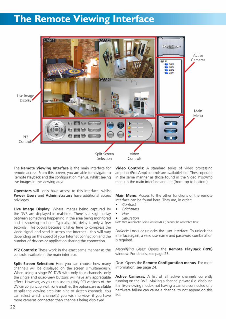
The Remote Viewing Interface
The Remote Viewing Interface is the main interface for remote access. From this screen, you are able to navigate to Remote Playback and the configuration menus, whilst seeing live images in the viewing area.
Operators will only have access to this interface, whilst Power Users and Administrators have additional access privileges.
Live Image Display: Where images being captured by the DVR are displayed in real-time. There is a slight delay between something happening in the area being monitored and it showing up here. Typically, this delay is only a few seconds. This occurs because it takes time to compress the video signal and send it across the Internet - this will vary depending on the speed of your Internet connection and the number of devices or application sharing the connection.
PTZ Controls: These work in the exact same manner as the controls available in the main interface.
Split Screen Selection: Here you can choose how many channels will be displayed on the screen simultaneously. When using a singe PC-DVR with only four channels, only the single and quad-view buttons will have any appreciable effect. However, as you can use multiply PCI versions of the DVR in conjunction with one another, the options are available to split the viewing area into nine or sixteen channels. You can select which channel(s) you wish to view, if you have more cameras connected than channels being displayed.
Video Controls: A standard series of video processing amplifier (ProcAmp) controls are available here. These operate in the same manner as those found in the Video ProcAmp menu in the main interface and are (from top to bottom):
Main Menu: Access to the other functions of the remote interface can be found here. They are, in order:
Contrast•Brightness•Hue•Saturation•
Note that Automatic Gain Control (AGC) cannot be controlled here.
Padlock: Locks or unlocks the user interface. To unlock the interface again, a valid username and password combination is required.
Magnifying Glass: Opens the Remote PlayBack (RPB) window. For details, see page 23.
Gear: Opens the Remote Configuration menus. For more information, see page 24.
Active Cameras: A list of all active channels currently running on the DVR. Making a channel private (i.e. disabling it in live-viewing mode), not having a camera connected or a hardware failure can cause a channel to not appear on this list.
Live ImageDisplay
PTZControls
Split Screen Selection
Video Controls
MainMenu
Active Cameras
22

The Remote Playback Interface
Playback Window: Where the footage being played back is displayed, arranged according to the viewing mode currently selected (see View Controls).
Playback Controls: The main playback controls are:
Plays the currently selected video(s).
Pauses the current playback. Unlike stopping the playback entirely, pausing playback keeps the currently selected video(s) open, and retains still images on the screen.
Stops playback, closing the selected videos.
Slows down playback. Press multiple times to lower playback speed further.
Shows the current playback speed. 1x is realtime, 0.5x is half speed and 2x is double speed (and so on).
Increases playback speed. Press multiple times to increase playback speed further.
Selects QUAD viewing mode. If you have more than four channels of video (achievable by using multiple PCI PC-DVR cards in conjunction with one another) you can select which four you wish to view.
The other viewing options work in the same way.
File search. Rather than using the timeline to manually find events, you can use the search dialog box. You can specify a period of time and a target recording mode, and you will see a list of all recordings made under those criteria immediately.
Timeline: The antithesis of the schedule. The numbers represent the hours of the day. Choose a day from the Date Selection area to change which day the timeline represents.
Date Selection: Here you can choose a range of footage you wish to view by selecting a date. The timeline will then display all recordings made on that date.
Record Mode Selection: You can choose to discriminate between recorded events based on the recording mode which triggered them to be recorded.
Playback Controls
Timeline
Playback Window
Date/TimeSelection
RecordMode
Selection
Return to Live View
23

Remote Configuration
24
The configuration screens available remotely offer the same options as the PC-DVR software itself. The format and layout of these screens is slightly different to those found in the DVR - and we’ll briefly cover some of the key differences here.
Basic: The screen shown above. Here you can change several common parameters, such as naming channels, toggling the audio channels on and off, and configuring the alarm output settings. Additionally, you’ll be able to set up automatic Windows login settings and the auto-reboot functions.
Camera: Here you can change the text displayed on each channel, apply a time stamp to the image, render the camera ‘private’ (stops it appearing in live-viewing mode) and toggle audio on or off. Additionally, you can choose how much detail is sent from the DVR for this channel - higher qualities look better, but require a faster Internet/network connection.
Schedule: Here you can change the recording schedule in much the same way as it is programmed in the main interface.
Alarm: You can configure the alarm mode and alter the settings for external sensors here.
Record: Gives you the option of configuring the recording quality of any given channel or mode. These settings can be configured in any way you want - for example, each recording mode on each channel can be assigned independently of one another. Additionally, if you wish to change the hard drive to which footage is recorded, this can be done from here.
Motion: Offers the same options as the motion detection menu available in the main application. You are able to alter which part of any given channel will be sensitive to motion, as well as configure how sensitive to motion it will be.
EMail: For configuring the auto-email settings. Again, the options available are practically identical to those found in the Auto-Mail menu in the main interface.
P.T.Z: Allows you to enter the various required information to correctly configure one of the PC’s COM ports to act as a PTZ controller. The actual PTZ controls (used to move the camera) are located in the lower left corner of the Remote Viewing interface, but the PTZ control settings will need to be defined before the PTZ controls will be operational.

25
Connecting via iPhone
Installing the iPhone App.
Step 1: Check to make sure you have space free on your iPhone to install applications, and you’re running a compatible version of the iPhone OS (see above). Navigate to the “App Store”.
Step 2: Turn on the “Search” function. In the search box, enter “SuperCam”. Several results should appear, with the exact match (the one you’ll want) should be at the top of the list.
Step 3: Click SuperCam, navigate to the into “Introduce” interface. Click the button which says “Free” - this will change immediately to a button which says “Install”. Click the “Install” button.
Step 4: Enter your iTunes Store password and click “OK”. Note: If this is the very first time you’re using the iTunes Store, then you’ll need to create a user account (instructions how to do this are provided by iTunes). If this is the first time you’ve accessed the iTunes Store from your iPhone but you already have an iTunes Store account, then you can use your existing account.
Step 5: Choose “Download”. The download will take a few minutes - once this has completed, continue with the installation. When installation is completed, the SuperCam icon will be displayed in your application group. Simply choose this icon to open the SuperCam application.
Step 6: Click on “System Setting”. A login screen will appear. Enter the public IP address of your network and port number (as if you were logging onto the PC-DVR via an Internet browser), and your username and password (for the PC-DVR, not your iPhone).
Using the iPhone App.
Viewing Live Images:
Once you’ve entered your password to access the PC-DVR, select “Live View”. By default, the live feed from channel 1 will be displayed.
Depending on the strength and integrity of your iPhone’s connection, there may be slight delay between the images displayed in Live Viewing and the actual live event. This can also lead to a drop in frame-rate.
Capturing Images:
You can capture still images directly from the Live View. Click once to capture picture.
Controlling PTZ Systems:
You can control any PTZ (Pan, Tilt, Zoom) systems remotely via your iPhone (assuming they are properly configured and connected to the PC-DVR via one of your computer’s COM ports.
Click to enter PTZ mode. Click Image View to view your captured pictures. Click or to switch to next or previous picture. Click to delete the current picture. PTZ Controls
The PTZ control panel looks very much like the one provided by the PC-DVR software for your computer.
The arrow buttons will move the camera, whilst the centre button will stop it (useful if the PTZ system is in cruise mode). The focus, iris and zoom controls are located to the bottom right of the screen.
Note that you will not be able to program patterns for cruise mode, or configure the advanced features of your PTZ system via the iPhone.
You can connect to, view live images from and control some settings on the PC-DVR using an iPhone. Unfortunately, you will not have the level of access and control that logging on via a computer running the proper software. Only recent releases of the PC-DVR support this function, as the iPhone is still quite new technology. You can grab an update for the PC-DVR software from our website (http://www.swannsecurity.com/downloads/drivers/pcdvr4net/latest).
Please Note: You’ll need to be running version 2.2 or higher of the iPhone operating system (usually abbreviated to iPhone OS v2.2). If you’re running a previous version, you won’t be able to connect to the PC-DVR until the phone is upgraded.
Mode Selection
Live Viewing
Snapshot
PTZ Controls

Problem: The PC-DVR software will not install correctly.Solution: Be sure that you’re not running “setup.exe” from a zipped folder – if so, extract all files before proceeding. Ensure that you are logged into your computer using an administrator account, otherwise you will not have the necessary permissions to install new software. Sometimes anti-virus/anti-spyware programs can conflict with the installation procedure, so turn these off during the process (then turn them back on!). Be sure there is enough space on the drive you’re installing the program to (more than 1GB free is recommended).
Problem: Software displays an error message saying “No Video Card” or “Wrong Version”.Solution: The computer is not detecting the card installed in the computer. This is most likely to be caused by the card not being properly connected to the computer. If you’re using the USB version of the PC-DVR, unplug the DVR and plug it back in - try using a different USB port if the problem persists. If you’re using the PCI version, you may need to open your computer’s case (be safe - unplug the computer first!) and ensure that the card is still properly inserted into the PCI slot.
If this does not fix the problem, then it indicates that the problem is most likely the device drivers installed to recognise and run the hardware. The best way to fix this is to run “setup.exe” again, and when prompted to Install/Repair/Remove, select “Remove”. Then, open your computer and remove the PC-DVR card. Re-install it to a different PCI slot. Then, reinstall the PC-DVR software. If this does not correct the problem, this indicates a severe hardware fault, and the card will need to be replaced.
Problem: The images from my cameras are distorted/missing.Solution: The video standard of your cameras may not match the setting in the PC-DVR software. Run “setup.exe” again, and select “Remove”. Then, reinstall the software and choose the correct video standard: the United States and Japan use NTSC, whilst Australia and Western Europe use PAL.
Problem: I need to reset the password on the PC-DVR.Solution: The only way to reset the password is to reinstall the PC-DVR software. Be sure to uninstall the program completely using Program Control/Add Remove Programs, found in the Control Panel.
Problem: The PC-DVR software displays an error message when run.Solution: You’re running a 64-bit operating system, whilst the PC-DVR has been designed for 32-bit systems. Unfortunately, there is little that can be done to rectify this incompatibility other than downgrading the operating system to a 32-bit version. Often a better solution is to purchase another computer system – the PC-DVR’s system requirements are low enough that it will work in a relatively inexpensive PC.
Problem: The PC-DVR software displays an error message saying “Cannot open Audio”.Solution: The PC-DVR attempts to route the microphone input on your sound card to the recording stream within the software. If the microphone input is already being routed somewhere else, typically by an Internet chat program, then the microphone will be inaccessible to the PC-DVR. Close these programs. If this does not correct the problem, the issue most likely stems from the drivers used for your sound card. Try updating/reinstalling the drivers.
Problem: Reinstalling the software for the USB version of the PC-DVR is not working correctly.Solution: When reinstalling the USB PC-DVR drivers and software, follow these guidelines: firstly, run the “setup.exe” file again and choose “Remove”. Open the Control Panel, and select “System”. Open the “Device Manager” and locate the device named “PCDVR3004F” (or similar). Right click and choose “Uninstall”. Disconnect the USB PC-DVR from the computer and reboot. Once it has rebooted, connect the PC-DVR to a different USB port. When prompted by the Found New Hardware Wizard to install the drivers, choose “Cancel”. Then, proceed with the installation as described on page 7.
Problem: I can’t install the software or want a new version.Solution: The most up-to-date version of the software is available from our website, www.swannsecurity.com. If you have any problems finding/downloading it, email our tech support team, and we’ll point you in the right direction.
Problem: I can’t connect to the DVR remotely!Solution: There are a few things that can go wrong with the remote connection process. Some of the most common are:
Using the wrong IP address. There are a couple of reasons why this might happen. Be sure you’re not using the private IP address to connect via the Internet. Also be sure that your Internet account has a static IP address, or you’ve set up Dynamic DNS (www.dyndns.com) correctly.
Using the wrong port number. Remember that you need to use the web port for the DVR, not the media or remote playback ports.
Using the wrong username/password combinations. If you’re using an username with administrator rights, you’ll need the password for that particular username, and not just an administrator password.
Ports are not forwarded properly. Your network needs to be configured correctly. Specifically, you need to configure your router/gateway to forward a port to the PC which has the DVR installed.
Check out www.portforward.com for a more in depth guide to forwarding ports than we could possibly jam into this manual.
See pages 20 - 23 for more details about networking the PC-DVR.
Troubleshooting Guide
26

PC-DVR4
Video
Video Format: PAL or NTSCVideo Inputs (USB Version): 4 x Composite RCA InputsVideo Inputs (PCI Version): 4 x Composite BNC InputsDisplay Resolution: NTSC: 640 x 480 PAL: 704 x 576Display Frame Rate (Global): NTSC: 30FPS, PAL 25FPS
Audio
Audio Inputs (USB): 2Audio Inputs (PCI): Sound Card in PC
Recording
Compression Format: MPEG4Recording Resolution: NTSC: 720 x 480, PAL: 720 x 576Recording Framerate (Global): NTSC: 60 FPS, PAL: 50FPSRecording Modes: Manual / Motion / ScheduleHDD Interface: PC Hard Drive(s)Hard Drive Support: Records to local hard drive(s)
Network
LAN Connection: Yes (via PC with network adaptor)Network Protocol: HTTP/Proprietary Extension
General - USB Version
Dimensions: 5.1” x 2.4” x 0.8” 130mm x 60mm x 20mmWeight: 5.2oz / 146g
General - PCI Version
Dimensions: 5.5” x 4.7 x 0.7 140mm x 120mm x 15mmWeight: 5.4 oz / 150G
27
Technical Specifications

© Swann Communications 2008Advanced security made easy™
Swann Communications warrants this product against defects in workmanship and material for a period of one (1) year from it’s original purchase date. You must present your receipt as proof of date of purchase for warranty validation. Any unit which proves defective during the stated period will be repaired without charge for parts or labour or replaced at the sole discretion of Swann. The end user is responsible for all freight charges incurred to send the product to Swann’s repair centres. The end user is responsible for all shipping costs incurred when shipping from and to any country other than the country of origin.
The warranty does not cover any incidental, accidental or consequential damages arising from the use of or the inability to use this product. Any costs associated with the fitting or removal of this product by a tradesman or other person or any other costs associated with its use are the responsibility of the end user. This warranty applies to the original purchaser of the product only and is not transferable to any third party. Unauthorized end user or third party modifications to any component or evidence of misuse or abuse of the device will render all warranties void.
By law some countries do not allow limitations on certain exclusions in this warranty. Where applicable by local laws, regulations and legal rights will take precedence.
Swann Communications USA Inc.12636 Clark Street
Santa Fe Springs CA 90670USA
Swann Communications PTY. LTD. Building 4, 650 Church Street,
Richmond, Victoria 3121Australia
Warranty Information
Helpdesk / Technical Support DetailsSwann Technical Support
All Countries E-mail: [email protected] Helpdesk
See http://www.worldtimeserver.com for information on time zones and the current time in Melbourne, Australia compared to your local time.
USA toll free1-800-627-2799
(Su, 2pm-10pm US PT)(M-Th, 6am-10pm US PT)
(F 6am-2pm US PT)USA Exchange & Repairs
562-777-2551(M-F, 9am-5pm US PT)
AUSTRALIA toll free1300 138 324
(M 9am-5pm AUS ET)(Tu-F 1am-5pm AUS ET)(Sa 1am-9am AUS ET)
NEW ZEALAND toll free0800 479 266
INTERNATIONAL +61 3 8412 4610