
Pearl Nano Coatings - Super-Hydrophobic, Scratch Resistant Nano Coatings
May 8, 2012 1
www.bruker-axs.com
Advanced Scratch Testing for Evaluation of Coatings
Suresh Kuiry, PhD
Bruker Nano Surfaces Division
Tribology and Mechanical Testing, 1717 Dell Ave, Campbell, CA 95008, U.S.A.
June 5, 2012 2
Introduction
• Scratch Tests Fundamentals
• Scratch Failure Regimes and Their Characteristics
• Existing Scratch Models
• CETR-UMT Scratch Tester
• Advanced Scratch Testing with CETR-UMT
• Some Scratch Test Results Obtained Using CETR-UMT
• Q & A
June 5, 2012 3
Why Scratch Test ?
Coatings are used for optical, microelectronic, packaging, biomedical, and
decorative applications to improve:
• tribological (lower friction),
• mechanical (wear/abrasion resistance),
• chemical (barrier to aggressive gases),
• optical, magnetic, and electrical properties of any substrate.
Functional behaviour of a coating is critical to its adhesion to the substrate.
Scratch test is one of widely used, fast, and effective methods to obtain the
critical loads that are related to adhesion properties of coating.
June 5, 2012 4
Scratch Tests
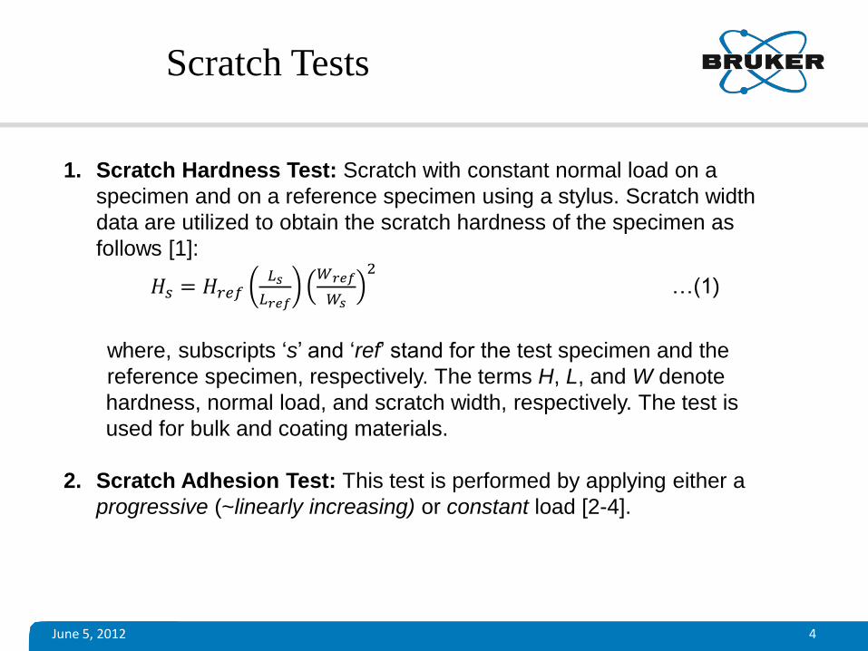
1. Scratch Hardness Test: Scratch with constant normal load on a
specimen and on a reference specimen using a stylus. Scratch width
data are utilized to obtain the scratch hardness of the specimen as
follows [1]:
𝐻𝑠 = 𝐻𝑟𝑒𝑓𝐿𝑠
𝐿𝑟𝑒𝑓
𝑊𝑟𝑒𝑓
𝑊𝑠
2 …(1)
where, subscripts ‘s’ and ‘ref’ stand for the test specimen and the
reference specimen, respectively. The terms H, L, and W denote
hardness, normal load, and scratch width, respectively. The test is
used for bulk and coating materials.
2. Scratch Adhesion Test: This test is performed by applying either a
progressive (~linearly increasing) or constant load [2-4].
June 5, 2012 5
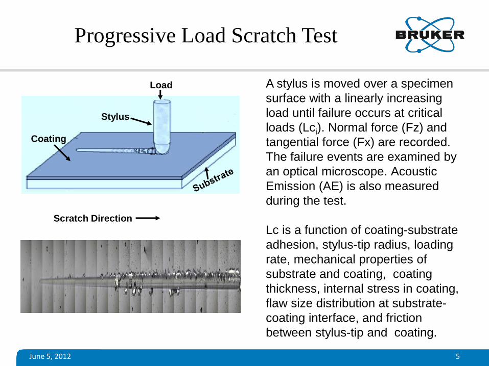
Progressive Load Scratch Test
A stylus is moved over a specimen
surface with a linearly increasing
load until failure occurs at critical
loads (Lci). Normal force (Fz) and
tangential force (Fx) are recorded.
The failure events are examined by
an optical microscope. Acoustic
Emission (AE) is also measured
during the test.
Lc is a function of coating-substrate
adhesion, stylus-tip radius, loading
rate, mechanical properties of
substrate and coating, coating
thickness, internal stress in coating,
flaw size distribution at substrate-
coating interface, and friction
between stylus-tip and coating.
Scratch Direction
Load
Coating
Stylus
June 5, 2012 6
Constant Load Scratch Test
Series of scratch tests are performed with constant normal loads on a
coating to obtain a load where the coating exhibits failure. Each scratch is
examined with an optical microscope for failure. The load at which such
failure of the coating occurs is termed as the critical load (Lc). Acoustic
Emission (AE) and Electrical Surface Resistance (ESR) are also measured
simultaneously during the constant load scratch test to supplement/confirm
the failure.
Constant load test requires more time but it provides greater statistical
confidence.
Progressive load test is suitable for rapid assessment and quality
assurance (QA) of coating. Hence, it is more popular for research and
development work on coating processes.
June 5, 2012 7
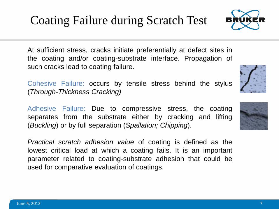
Coating Failure during Scratch Test
At sufficient stress, cracks initiate preferentially at defect sites in
the coating and/or coating-substrate interface. Propagation of
such cracks lead to coating failure.
Cohesive Failure: occurs by tensile stress behind the stylus
(Through-Thickness Cracking)
Adhesive Failure: Due to compressive stress, the coating
separates from the substrate either by cracking and lifting
(Buckling) or by full separation (Spallation; Chipping).
Practical scratch adhesion value of coating is defined as the
lowest critical load at which a coating fails. It is an important
parameter related to coating-substrate adhesion that could be
used for comparative evaluation of coatings.
June 5, 2012 8
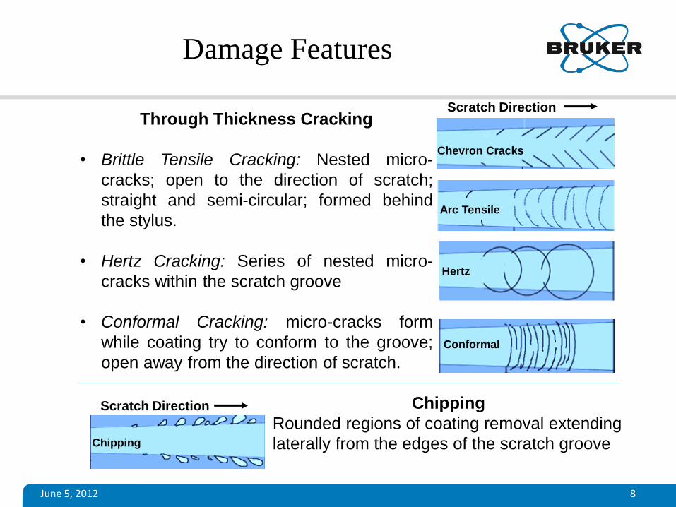
Damage Features
Through Thickness Cracking
• Brittle Tensile Cracking: Nested micro-
cracks; open to the direction of scratch;
straight and semi-circular; formed behind
the stylus.
• Hertz Cracking: Series of nested micro-
cracks within the scratch groove
• Conformal Cracking: micro-cracks form
while coating try to conform to the groove;
open away from the direction of scratch.
Chevron Cracks
Arc Tensile
Conformal
Chipping
Rounded regions of coating removal extending
laterally from the edges of the scratch groove Chipping
Hertz
Scratch Direction
Scratch Direction
June 5, 2012
Damage Features
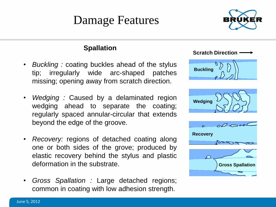
Spallation
• Buckling : coating buckles ahead of the stylus
tip; irregularly wide arc-shaped patches
missing; opening away from scratch direction.
• Wedging : Caused by a delaminated region
wedging ahead to separate the coating;
regularly spaced annular-circular that extends
beyond the edge of the groove.
• Recovery: regions of detached coating along
one or both sides of the grove; produced by
elastic recovery behind the stylus and plastic
deformation in the substrate.
• Gross Spallation : Large detached regions;
common in coating with low adhesion strength.
Gross Spallation
Buckling
Wedging
Recovery
Scratch Direction
June 5, 2012 10
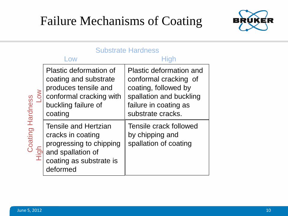
Failure Mechanisms of Coating
Tensile crack followed
by chipping and
spallation of coating
Plastic deformation and
conformal cracking of
coating, followed by
spallation and buckling
failure in coating as
substrate cracks.
Plastic deformation of
coating and substrate
produces tensile and
conformal cracking with
buckling failure of
coating
Tensile and Hertzian
cracks in coating
progressing to chipping
and spallation of
coating as substrate is
deformed
Substrate Hardness
Low High
Coating H
ard
ness
H
igh
Low
June 5, 2012 11
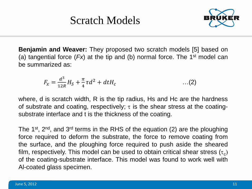
Scratch Models
Benjamin and Weaver: They proposed two scratch models [5] based on
(a) tangential force (Fx) at the tip and (b) normal force. The 1st model can
be summarized as:
𝐹𝑥 =𝑑3
12𝑅𝐻𝑆 +
𝜋
4𝜏𝑑2 + 𝑑𝑡𝐻𝑐 …(2)
where, d is scratch width, R is the tip radius, Hs and Hc are the hardness
of substrate and coating, respectively; t is the shear stress at the coating-
substrate interface and t is the thickness of the coating.
The 1st, 2nd, and 3rd terms in the RHS of the equation (2) are the ploughing
force required to deform the substrate, the force to remove coating from
the surface, and the ploughing force required to push aside the sheared
film, respectively. This model can be used to obtain critical shear stress (tc)
of the coating-substrate interface. This model was found to work well with
Al-coated glass specimen.
June 5, 2012 12
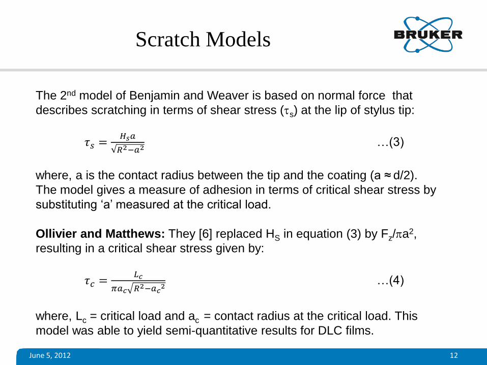
The 2nd model of Benjamin and Weaver is based on normal force that
describes scratching in terms of shear stress (ts) at the lip of stylus tip:
𝜏𝑠 =𝐻𝑠𝑎
𝑅2−𝑎2 …(3)
where, a is the contact radius between the tip and the coating (a ≈ d/2).
The model gives a measure of adhesion in terms of critical shear stress by
substituting ‘a’ measured at the critical load.
Ollivier and Matthews: They [6] replaced HS in equation (3) by Fz/pa2,
resulting in a critical shear stress given by:
𝜏𝑐 =𝐿𝑐
𝜋𝑎𝑐 𝑅2−𝑎𝑐2 …(4)
where, Lc = critical load and ac = contact radius at the critical load. This
model was able to yield semi-quantitative results for DLC films.
Scratch Models
June 5, 2012 13
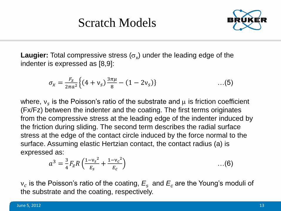
Laugier: Total compressive stress (sx) under the leading edge of the
indenter is expressed as [8,9]:
𝜎𝑥 =𝐹𝑧
2𝜋𝑎2 4 + ν𝑠3𝜋𝜇
8− 1 − 2ν𝑠 …(5)
where, ν𝑠 is the Poisson’s ratio of the substrate and m is friction coefficient
(Fx/Fz) between the indenter and the coating. The first terms originates
from the compressive stress at the leading edge of the indenter induced by
the friction during sliding. The second term describes the radial surface
stress at the edge of the contact circle induced by the force normal to the
surface. Assuming elastic Hertzian contact, the contact radius (a) is
expressed as:
𝑎3 =3
4𝐹𝑧𝑅
1−ν𝑠2
𝐸𝑠+
1−ν𝑐2
𝐸𝑐 …(6)
ν𝑐 is the Poisson’s ratio of the coating, Es and Ec are the Young’s moduli of
the substrate and the coating, respectively.
Scratch Models
June 5, 2012 14
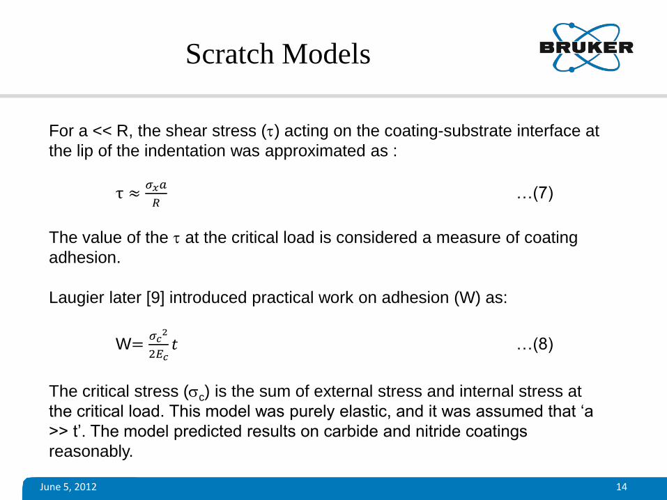
For a << R, the shear stress (t) acting on the coating-substrate interface at
the lip of the indentation was approximated as :
τ ≈𝜎𝑥𝑎
𝑅 …(7)
The value of the t at the critical load is considered a measure of coating
adhesion.
Laugier later [9] introduced practical work on adhesion (W) as:
W=𝜎𝑐
2
2𝐸𝑐𝑡 …(8)
The critical stress (sc) is the sum of external stress and internal stress at
the critical load. This model was purely elastic, and it was assumed that ‘a
>> t’. The model predicted results on carbide and nitride coatings
reasonably.
Scratch Models
June 5, 2012 15
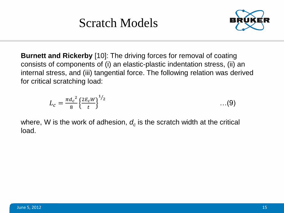
Burnett and Rickerby [10]: The driving forces for removal of coating
consists of components of (i) an elastic-plastic indentation stress, (ii) an
internal stress, and (iii) tangential force. The following relation was derived
for critical scratching load:
𝐿𝑐 =𝜋𝑑𝑐
2
8
2𝐸𝑐𝑊
𝑡
12 …(9)
where, W is the work of adhesion, dc is the scratch width at the critical
load.
Scratch Models
June 5, 2012 16
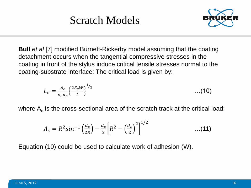
Bull et al [7] modified Burnett-Rickerby model assuming that the coating
detachment occurs when the tangential compressive stresses in the
coating in front of the stylus induce critical tensile stresses normal to the
coating-substrate interface: The critical load is given by:
𝐿𝑐 =𝐴𝑐
ν𝑐𝜇𝑐
2𝐸𝑐𝑊
𝑡
12 …(10)
where Ac is the cross-sectional area of the scratch track at the critical load:
𝐴𝑐 = 𝑅2𝑠𝑖𝑛−1 𝑑𝑐
2𝑅−
𝑑𝑐
2𝑅2 −
𝑑𝑐
2
2 1/2
…(11)
Equation (10) could be used to calculate work of adhesion (W).
Scratch Models
June 5, 2012 17
The existing models invariably use assumptions and simplifications to deal
with the inherent complexity of any scratching process, which involves
large number of variables. Hence, the existing scratch models experience
great difficulties to give a complete analytical description of the mechanics
of scratch testing. Predicted scratch adhesion values from such models
differ widely from the actual scratch test results.
Evaluation and fine-tuning of such scratch models certainly requires
continuous developmental effort with an objective to obtain a standard
model that would give comprehensive description of any scratching
process.
Limitation of Scratch Models
June 5, 2012 18
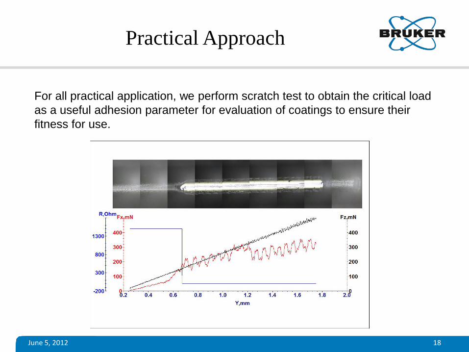
For all practical application, we perform scratch test to obtain the critical load
as a useful adhesion parameter for evaluation of coatings to ensure their
fitness for use.
Practical Approach
June 5, 2012 19
Scratch Tester (CETR-UMT)
CETR-Universal Materials Tester (CETR-UMT) is a unique test and measurement system that can be used for Scratch Testing: • Constant load scratch Test for hardness and adhesion
• Progressive load scratch Test for practical adhesion
• Electrical Contact Resistance (ECR)
• Electrical Surface Resistance (ESR)
• Acoustic Emission (AE)
• in-situ scratch depth profiling using capacitance sensor, tip-
displacement (Z-encoder)
• Optical microcopy and AFM for imaging
• 3D-Optical Microscopy (interferometry) for imaging and metrology
June 5, 2012 20
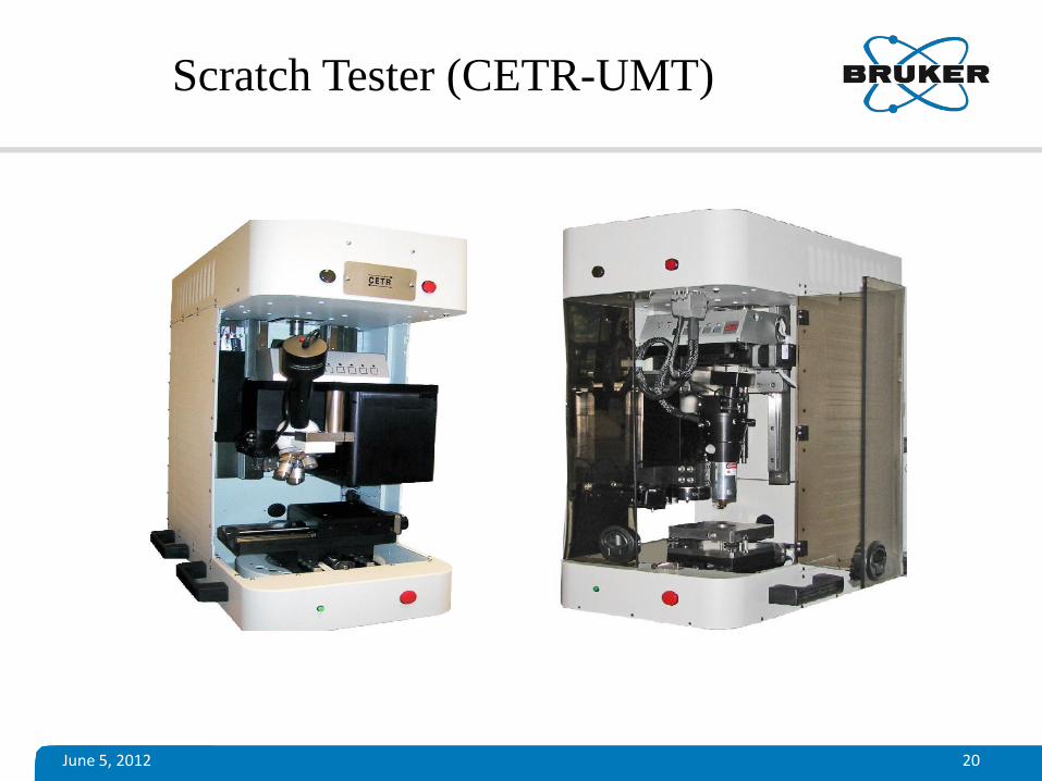
Scratch Tester (CETR-UMT)
June 5, 2012 21
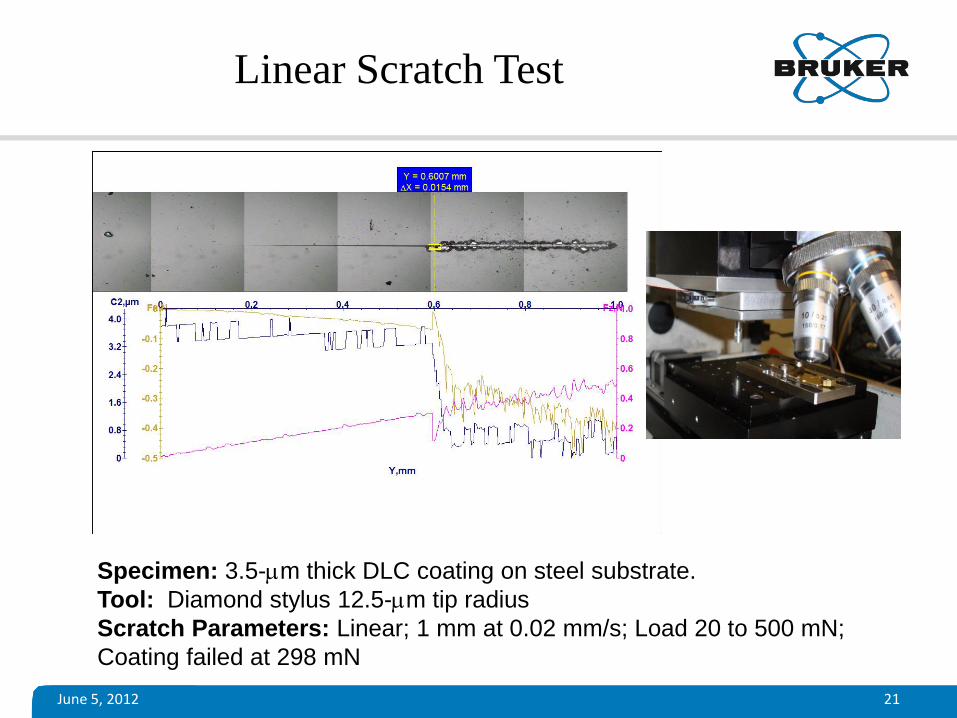
Linear Scratch Test
Specimen: 3.5-mm thick DLC coating on steel substrate.
Tool: Diamond stylus 12.5-mm tip radius
Scratch Parameters: Linear; 1 mm at 0.02 mm/s; Load 20 to 500 mN;
Coating failed at 298 mN
June 5, 2012 22
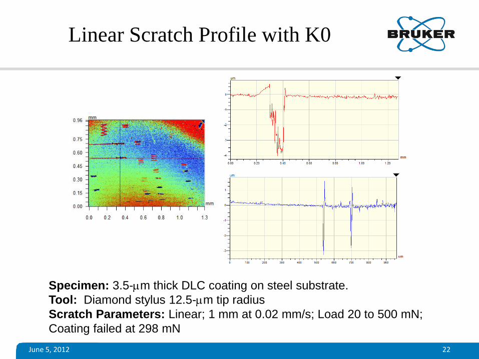
Linear Scratch Profile with K0
Specimen: 3.5-mm thick DLC coating on steel substrate.
Tool: Diamond stylus 12.5-mm tip radius
Scratch Parameters: Linear; 1 mm at 0.02 mm/s; Load 20 to 500 mN;
Coating failed at 298 mN
June 5, 2012 23
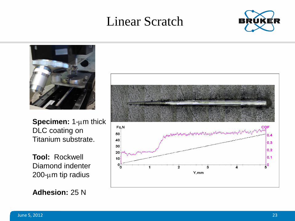
Linear Scratch
Specimen: 1-mm thick
DLC coating on
Titanium substrate.
Tool: Rockwell
Diamond indenter
200-mm tip radius
Adhesion: 25 N
June 5, 2012 24
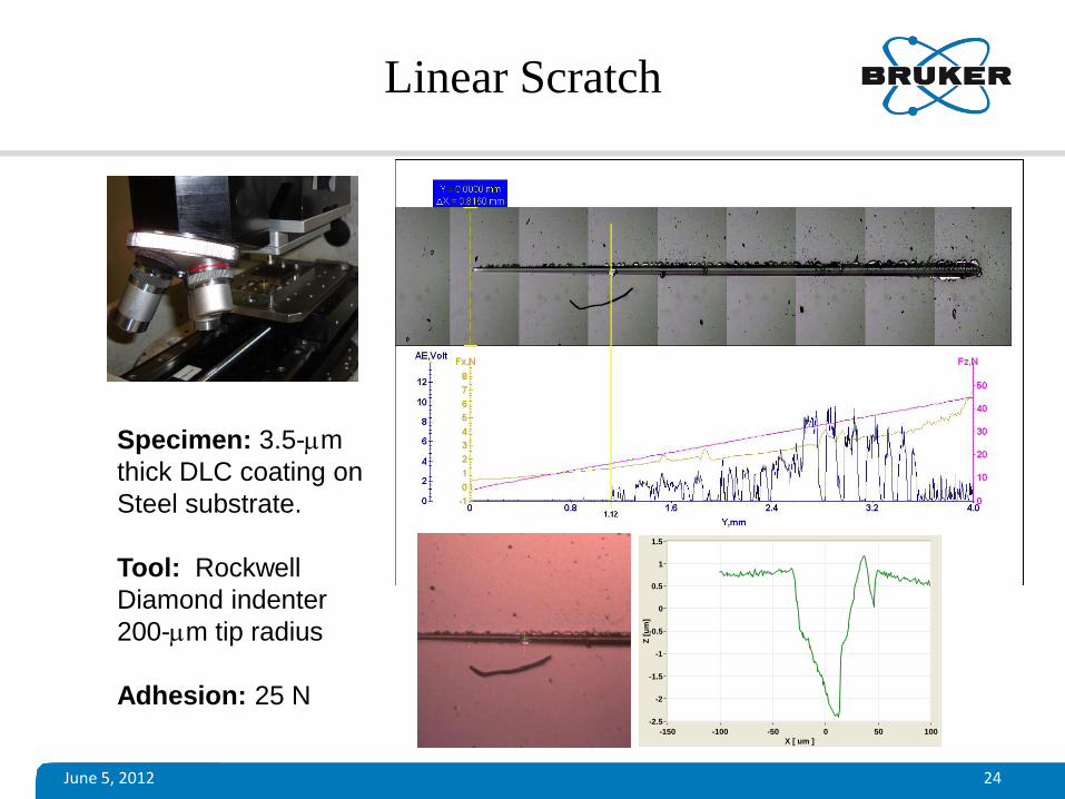
Specimen: 3.5-mm
thick DLC coating on
Steel substrate.
Tool: Rockwell
Diamond indenter
200-mm tip radius
Adhesion: 25 N
X [ um ]
-150 -100 -50 0 50 100
Z [
um
]
-2.5
-2
-1.5
-1
-0.5
0
0.5
1
1.5
Linear Scratch
June 5, 2012 25
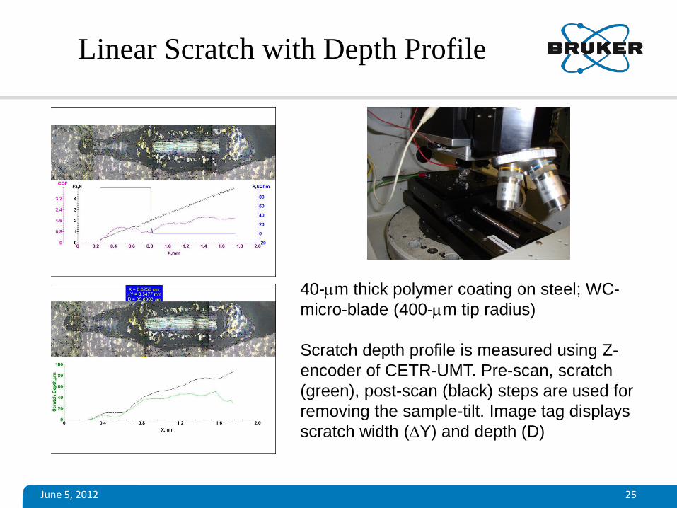
Linear Scratch with Depth Profile
40-mm thick polymer coating on steel; WC-
micro-blade (400-mm tip radius)
Scratch depth profile is measured using Z-
encoder of CETR-UMT. Pre-scan, scratch
(green), post-scan (black) steps are used for
removing the sample-tilt. Image tag displays
scratch width (Y) and depth (D)
June 5, 2012 26
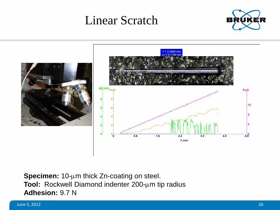
Linear Scratch
Specimen: 10-mm thick Zn-coating on steel.
Tool: Rockwell Diamond indenter 200-mm tip radius
Adhesion: 9.7 N
June 5, 2012 27
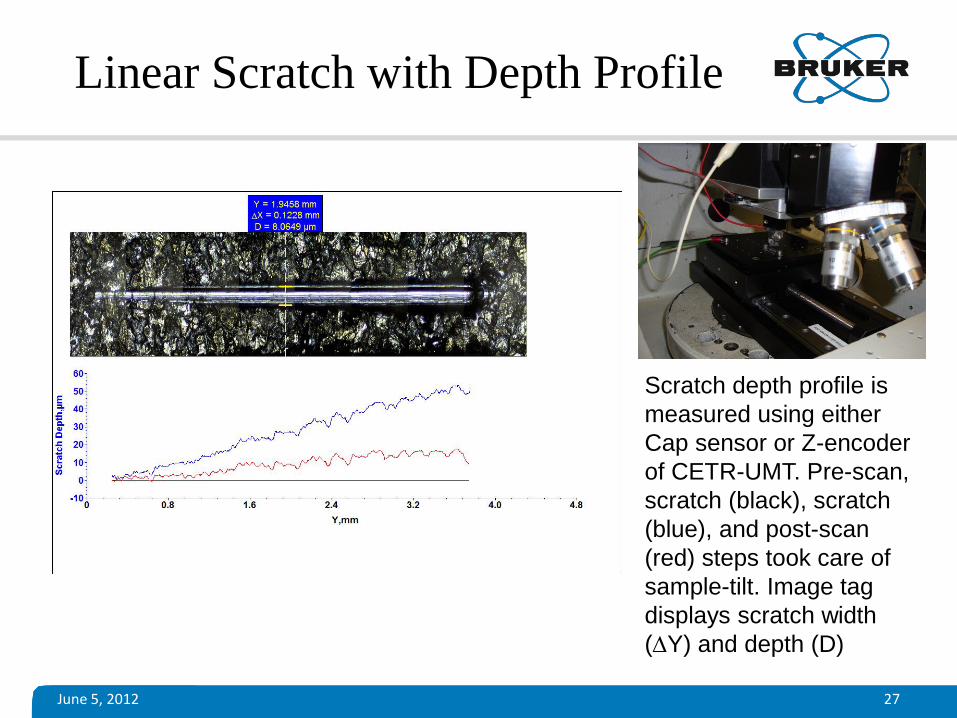
Linear Scratch with Depth Profile
Scratch depth profile is
measured using either
Cap sensor or Z-encoder
of CETR-UMT. Pre-scan,
scratch (black), scratch
(blue), and post-scan
(red) steps took care of
sample-tilt. Image tag
displays scratch width
(Y) and depth (D)
June 5, 2012 28
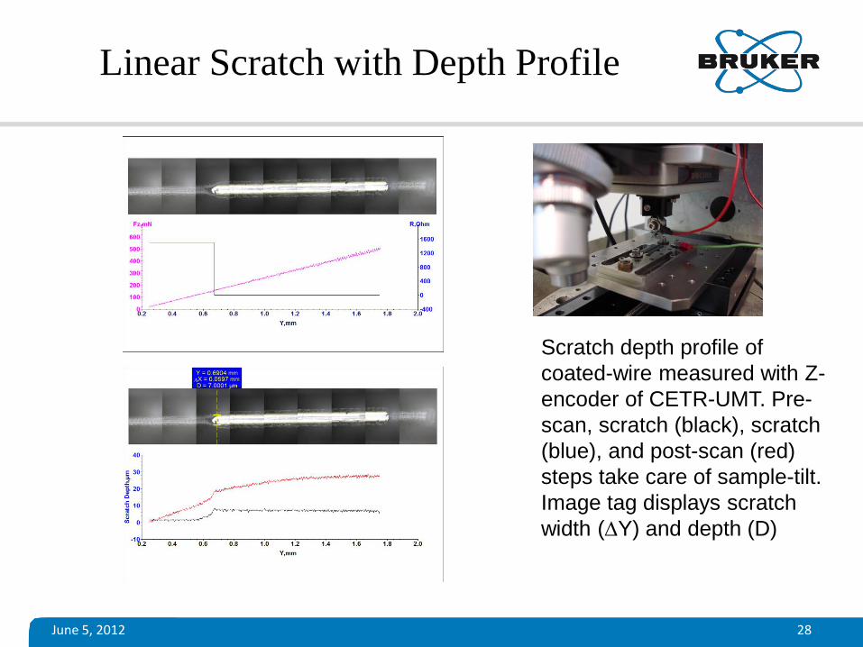
Linear Scratch with Depth Profile
Scratch depth profile of
coated-wire measured with Z-
encoder of CETR-UMT. Pre-
scan, scratch (black), scratch
(blue), and post-scan (red)
steps take care of sample-tilt.
Image tag displays scratch
width (Y) and depth (D)

June 5, 2012 29
Linear Scratch for Adhesion Energy
Specimen: Polymer dots (1.2 mm dia x 25 mm) on ceramic substrate.
Tool: Special Tool-steel micro-blade; Fx increased during delamination of
a polymer dot. Adhesion Energy calculated from area of the triangle under
Fx plot. Adhesion Energy: 490 erg
X [ um ]
-300 -200 -100 0 100 200 300
Z [
um
]
-5
0
5
10
15
20
25
June 5, 2012 30
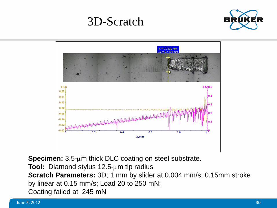
3D-Scratch
Specimen: 3.5-mm thick DLC coating on steel substrate.
Tool: Diamond stylus 12.5-mm tip radius
Scratch Parameters: 3D; 1 mm by slider at 0.004 mm/s; 0.15mm stroke
by linear at 0.15 mm/s; Load 20 to 250 mN;
Coating failed at 245 mN
June 5, 2012 31
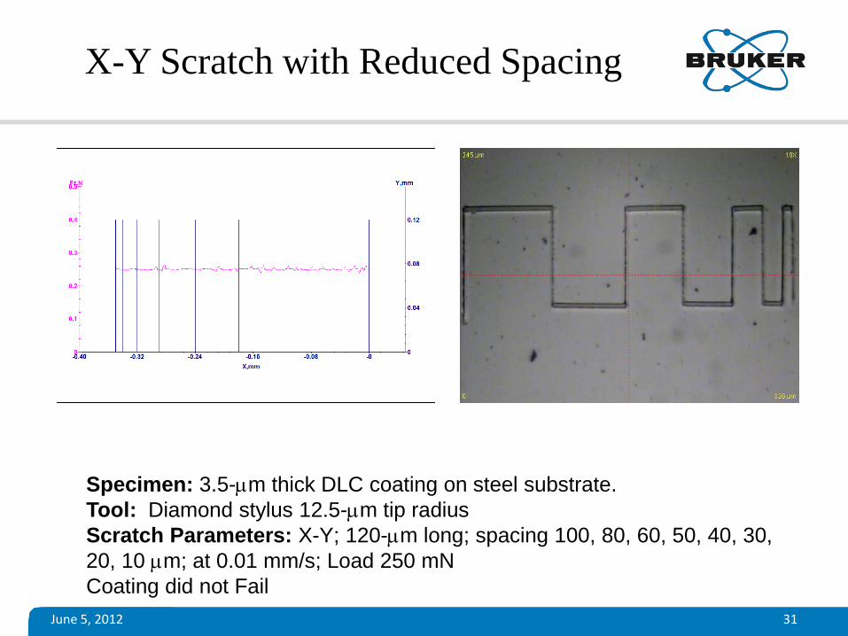
X-Y Scratch with Reduced Spacing
Specimen: 3.5-mm thick DLC coating on steel substrate.
Tool: Diamond stylus 12.5-mm tip radius
Scratch Parameters: X-Y; 120-mm long; spacing 100, 80, 60, 50, 40, 30,
20, 10 mm; at 0.01 mm/s; Load 250 mN
Coating did not Fail
June 5, 2012 32
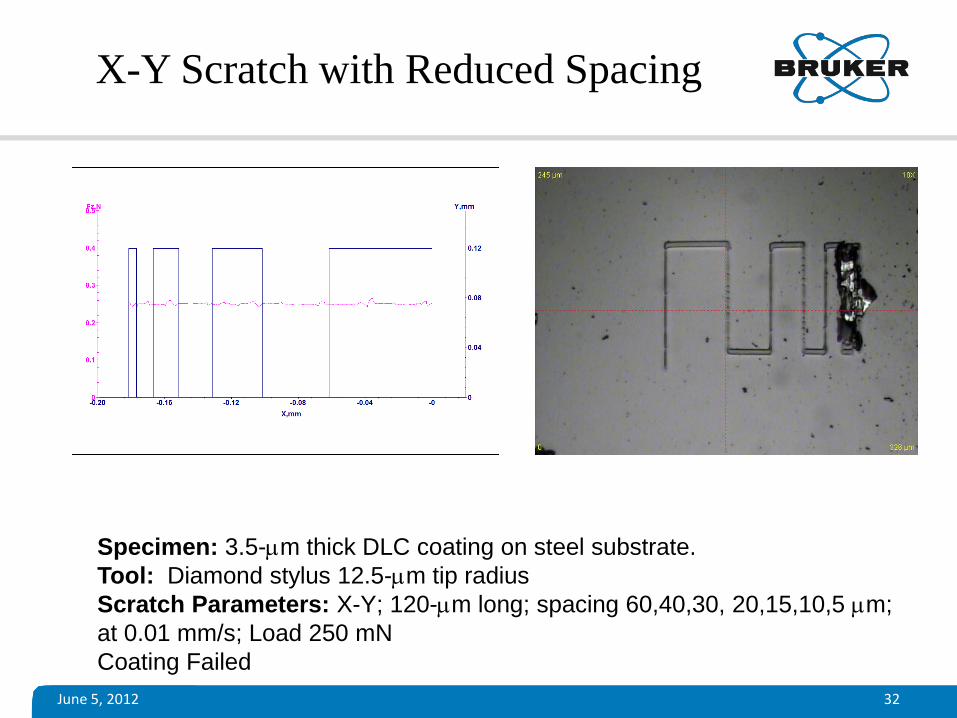
X-Y Scratch with Reduced Spacing
Specimen: 3.5-mm thick DLC coating on steel substrate.
Tool: Diamond stylus 12.5-mm tip radius
Scratch Parameters: X-Y; 120-mm long; spacing 60,40,30, 20,15,10,5 mm;
at 0.01 mm/s; Load 250 mN
Coating Failed
June 5, 2012 33
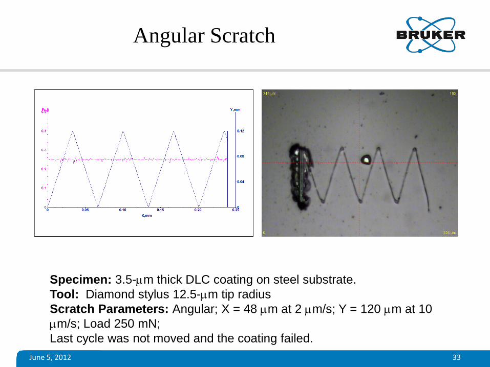
Angular Scratch
Specimen: 3.5-mm thick DLC coating on steel substrate.
Tool: Diamond stylus 12.5-mm tip radius
Scratch Parameters: Angular; X = 48 mm at 2 mm/s; Y = 120 mm at 10
mm/s; Load 250 mN;
Last cycle was not moved and the coating failed.
June 5, 2012 34
Concluding Remarks
• Scratch test is a widely used test procedure for evaluation of coatings.
• CETR-UMT can perform advanced scratch tests (Constant load, Progressive, 3D, X-Y, Angular etc) to evaluate the adhesion properties of coating.
• CETR-UMT Test system can perform comprehensive evaluation of coatings by automated imaging and profiling of scratch.
June 5, 2012 35
References
1. ASTM Standard G171 (03) – Standard Test Method for Scratch Hardness of Materials Using a Diamond Stylus.
2. ASTM Standard C1624 (05) –Standard Test Method for Adhesion Strength and Mechanical Failure Modes of Ceramic Coatings by Quantitative Single Point Scratch testing
3. S. J. Bull, Surf. Coat. Technol. 50 (1991) 25. 4. S. J. Bull, Trib. Inter. 30 (1997) 491. 5. P. Benjamin, C. Weaver, Proc. R. Soc. London, A 254 (1960) 163. 6. B. Ollivier, J. Matthews, J. Adhesion Technol., 8 (1994) 651. 7. S.J. Bull, D.S. Rickerby, A. Matthews, A. Leyland, A.R. Pace, J. Valli, Surf. Coat.
Technol. 36 (1988) 503. 8. M.T. Laugier, Thin Solid Films 76 (1981) 289; 117 (1984) 243. 9. M.T. Laugier, J. Mater. Sci. 21 (1986) 2269. 10. P.J. Burnett, D.S. Rickerby, Thin Solid Films 154 (1987) 403; 157 (1988) 233.