Advanced Scintillator Detector R&D Towards a 50 kt Ultra-High Segmentation Fe-Scintillator Detector.
22
Advanced Scintillator Detector R&D Towards a 50 kt Ultra-High Segmentation Fe-Scintillator Detector
-
Upload
buck-chapman -
Category
Documents
-
view
230 -
download
0
Transcript of Advanced Scintillator Detector R&D Towards a 50 kt Ultra-High Segmentation Fe-Scintillator Detector.
Advanced Scintillator Detector R&D
Towards a 50 kt Ultra-High Segmentation Fe-Scintillator
Detector

Motivation
Very Rich Physics program at a Factory Long Baseline oscillation program at 20
GeV Factory pointing to a 50 kt detector e
e
e
Detector capabilities Detect muons and determine sign
– At as low a threshold as is possible • < 4 Gev/c• 2 Gev/c would be desirable
Detect electrons/positrons– Determine sign??
Detect leptons– This is a difficult task in a massive
detector -detection best suited to specialized detectors
• Kinematics can be used in fine-grained detectors, however
Compared to what is required at D0 or CDF (or LHC) – this is rather simple

Detector Scenarios
Options Liquid Argon TPC
Fully reconstructed events – Bubble chamber-like event topologies
Excellent! Electron and hadronic calorimetry
External muon system required for muon sign and momentum– Unless very-large magnet used
Magnetized Fe-Scintillator Unmatched muon detection capability Electron/hadronic energy detection
dependent on segmentation Water Ĉerenkov
Scalable to very large detector– Best cost to size – Surface area
detectors Full containment excellent only for
low energy beam Poorest pattern recognition
capabilities

Detector Development at
Fermilab
Scintillation Detector work, however, has been a major R&D and construction effort over the last decade at Fermilab
CDF end-caps and shower max CDF TOF D0 Fiber tracker
VLPC Development D0 Preshower detectors D0 Central muon counters CMS Calorimeters MINOS

Detector Development
This work has driven the development of significant infrastructure
Scintillation Detector Development Laboratory
Extruded scintillator Fiber characterization and test
Thin-Film facility Fiber processing
– Mirroring and coatings Photocathode work Diamond polishing
CNC Routing Tile-fiber detectors
Machine Development Diamond polishing Optical connector development High-density Photodetector
packaging (VLPC)

Detector Development
Detector R&D on scintillation detectors is appealing, since even if a large Fe-Scintillator neutrino detector is not the optimal choice for a future physics programs - the detector technology is general purpose
Not the case with LAr TPC or Water Ĉ These are not likely to see major
application outside physics
Scintillation detectors EM and hadronic calorimetry Shower max detectors Preshower detectors Photon vetos Fiber tracker Muon tracking/hodoscopes General purpose trigger hodoscopes Time-of-Flight

Strawman 50 kt UHS Fe-Scint Detector
A detector with 10X the fiducial mass of MINOS
⅛-¼ Xo longitudinal sampling (2.2-4.4mm Fe - 5-10 X MINOS)
1 cm transverse segmentation 1 cm base triangles – yields about 1 mm
position resolution for mips From D0 preshower test data
This begins to look like a magnetized Soudan with much better energy resolution
What does this imply? Scintillator
0.3 kt 12 kt (24) Steel
Straightforward extrapolation Photodetector
1.5 X10⁵ fibers 25 (50) X 106!– Note: MINOS reads out both ends of the
fiber and then multiplexes fiber to photodetector 4:1
– This example is non-multiplexed

Detector Issues
Can this detector be built today? NO!
What are the issues? – There are three: Scintillator Fiber Photodetector
Lets take the first, first Can we make this much
scintillator?
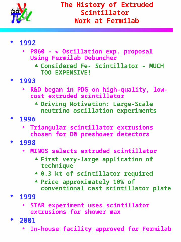
The History of Extruded Scintillator
Work at Fermilab
1992 P860 – Oscillation exp. proposal Using
Fermilab Debuncher Considered Fe- Scintillator – MUCH
TOO EXPENSIVE! 1993
R&D began in PDG on high-quality, low-cost extruded scintillator
Driving Motivation: Large-Scale neutrino oscillation experiments
1996 Triangular scintillator extrusions chosen
for D0 preshower detectors 1998
MINOS selects extruded scintillator First very-large application of
technique 0.3 kt of scintillator required Price approximately 10% of
conventional cast scintillator plate 1999
STAR experiment uses scintillator extrusions for shower max
2001 In-house facility approved for Fermilab

Fermilab Facility
All equipment for basic system has been specified – PO to be placed this week!
Up to 4X the production rate of MINOS Expect better quality/uniformity Some cost reduction over MINOS
$5/kg? Can extrapolate to many kt with outside
vendor involvement
Polymer Dopant

Scintillation Detectors
The scintillator production will be challenging, but can be done
The Fiber/Photodetector issues are more difficult
Readout Optimization For a given detector cell:dE/dx Scintillation light ()
Readout light (WLS fiber) (Signal Charge
(photodetector) ()
= Scintillation efficiency – 3%= WLS fiber capture efficiency – 5% = QE X gain – 0.8 X 50k (VLPC)
Note: Both fiber and PD costs go like the cross-sectional area

Scintillation Detectors
MINOS light yield (my apologies if this is not the latest&best data)
1X4 cm extrusion 1.2 mm WLS readout fiber to MAPMT
Scintillation Detectors
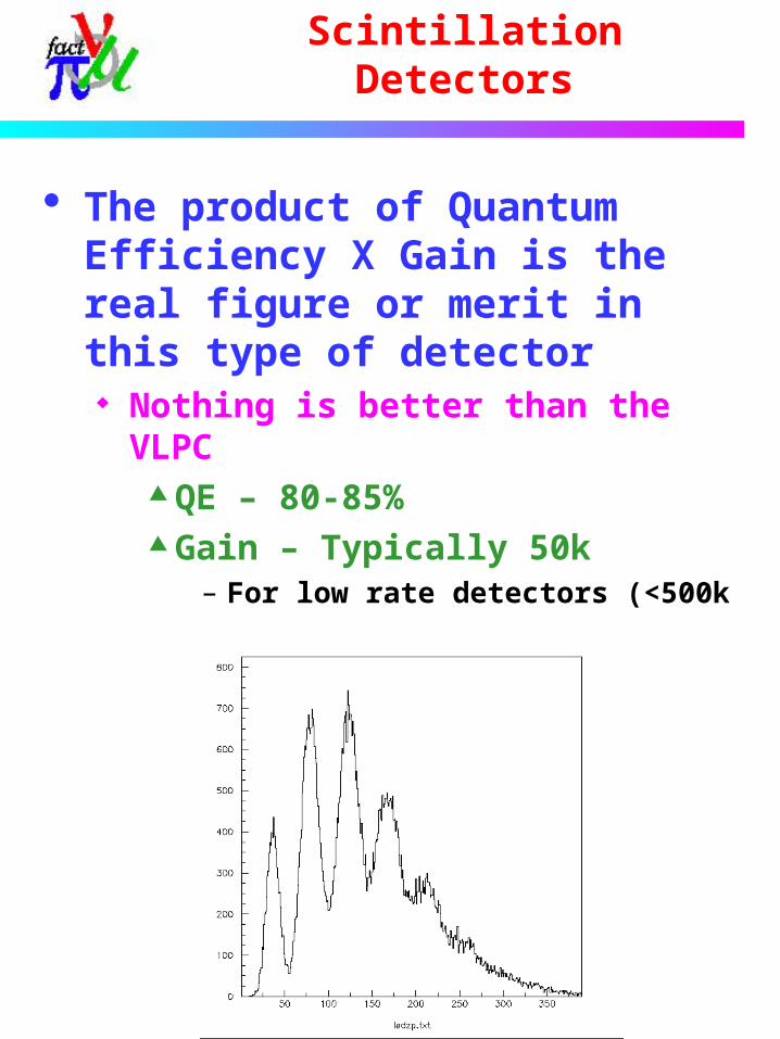
The product of Quantum Efficiency X Gain is the real figure or merit in this type of detector Nothing is better than the
VLPC QE – 80-85% Gain – Typically 50k
– For low rate detectors (<500k pe/sec) – 100k

VLPC Readout of MINOS extrusions
MINOS 1 X 4 extrusion, 1.2 mm readout fiber 1.2 mm VLPC Data
Since the VLPC cassette uses 0.965mm fiber, this is corrected data [X(1.2/0.965)2]
0.5 mm VLPC Data – No correction needed
Number of photoelectrons vs fiber length
1
10
100
0 1 2 3 4 5 6 7 8 9 10
Distance along the fiber (m)
Nu
mb
er o
f P
E
L=5.8 m,1.2 mm fiber - VLPC
Minos data,L=5.4 m 1.2mm fiber, PMT
0.5 mm fiber L=5.3 (VLPC)
Expon. (L=5.8 m,1.2 mm fiber - VLPC)
Expon. (Minos data,L=5.4 m 1.2mm fiber, PMT)
Expon. (0.5 mm fiber L=5.3 (VLPC))
VLPC Readout of MINOS extrusions
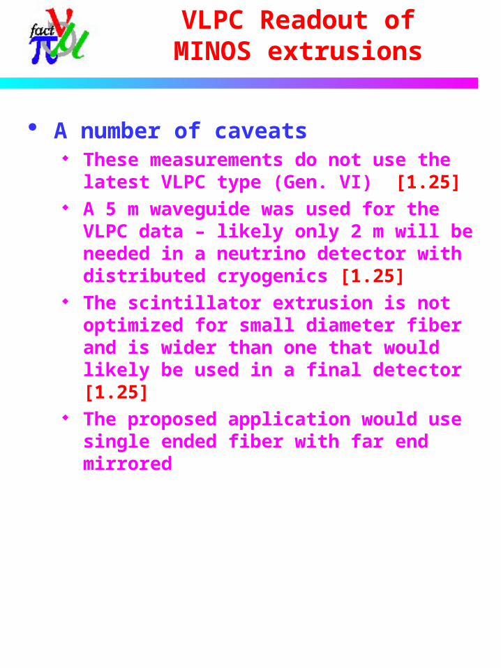
A number of caveats These measurements do not use the
latest VLPC type (Gen. VI) [1.25] A 5 m waveguide was used for the
VLPC data – likely only 2 m will be needed in a neutrino detector with distributed cryogenics [1.25]
The scintillator extrusion is not optimized for small diameter fiber and is wider than one that would likely be used in a final detector [1.25]
The proposed application would use single ended fiber with far end mirrored

Single-ended fiber readout
Results from D0 fiber tracker Cosmic Test
2.5 m active fiber 0.83 mm readout 1 end – far end
mirrored 11.5 m waveguide Effective Attenuation Length = 16 m!

Detector Optimization
All of this indicates that the light yield for Fe-Scintillator detector with VLPC readout will be very high!
Even with 0.4 mm fiber – estimate at this time that the yield would be higher than MINOS baseline at all positions up to 8-10m fiber length.
This has an enormous impact on fiber cost
For example – MINOS $4M is reduced to roughly $450k
The same is true for the photodetector
A 5 X 10 element array (.4mm) would cost the same or less than D0’s 2 X 4 element array (1mm) - $240
Near-Term R&D Plans
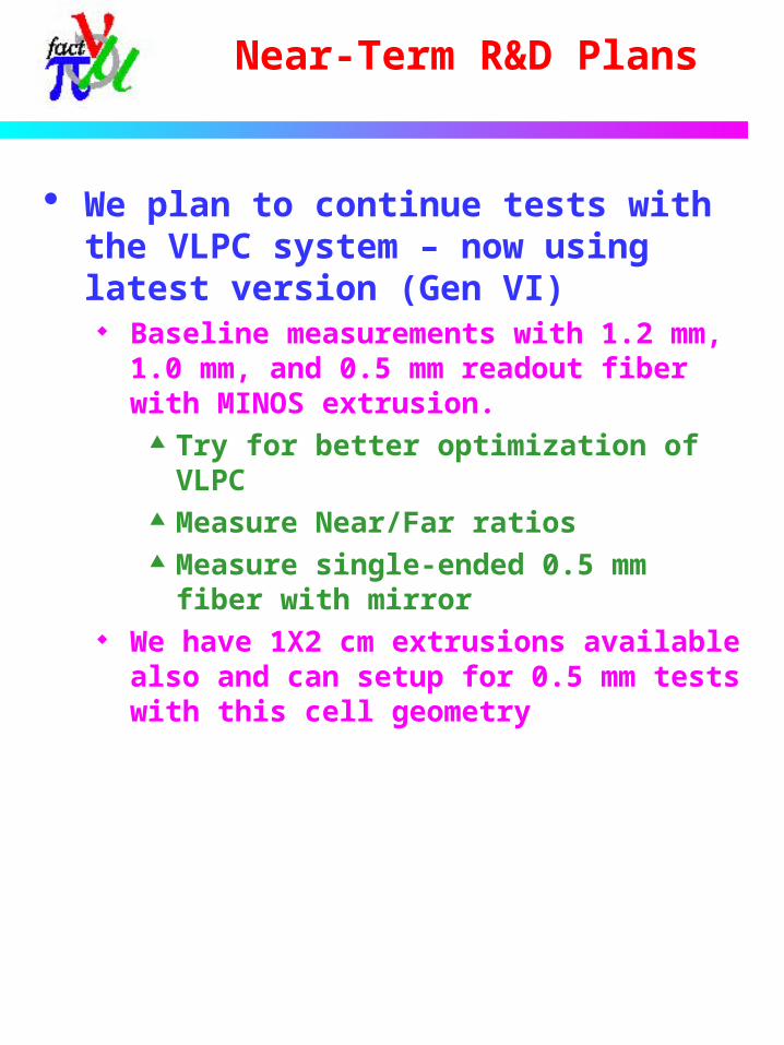
We plan to continue tests with the VLPC system – now using latest version (Gen VI)
Baseline measurements with 1.2 mm, 1.0 mm, and 0.5 mm readout fiber with MINOS extrusion.
Try for better optimization of VLPC
Measure Near/Far ratios Measure single-ended 0.5 mm
fiber with mirror We have 1X2 cm extrusions
available also and can setup for 0.5 mm tests with this cell geometry

VLPC R&D
Lawrence Semiconductor Research Laboratory (LSRL) has completed a SBIR Phase I grant to develop the next generation VLPC ($100k).
Collaborated with Boeing Boeing now has LSRL make all the
silicon epitaxy for their IR sensors – similar technology to VLPC– Better equipment than was used at
Boeing for D0– Better yield/higher uniformity– 5” to 8” wafer ( D0 used 3” )
• All projects to lowering cost
Very successful Better uniformity demonstrated
– X10 Much lower defect density (X40)
– Higher yield Produced enough epitaxial material in
this phase to produce 320k pixels of the D0 type– Very low cost compared to D0

VLPC R&D
Phase II grant has been awarded $750k Continue optimization Process wafers from Phase I
Produced D0-type arrays for detailed device analysis
Produce higher density arrays Goal: Demonstrate cost reduction at X10

VLPC R&D
The major difficulty to go to smaller VLPC pixel is the higher density
The D0 system uses “Cassettes” that hold 1024 channels each
To get to 10X the density – requires cold end electronics
Cannot individually bring signals out This has been done at Boeing
For space applications Will be expensive to develop
– $1M estimated program cost– Maybe cheaper if some CMOS MUX design
help can be provided by Fermilab or others– Part of program cost might be part of Phase
II SBIR However, Boeing believes that a X10 cost
reduction from D0 is possible - $5/ch
MUXdie
VLPC Active
Volume
plastic fiber
CMOS
VLPC die

Conclusions
Scintillator detector technology R&D will be part of Fermilab’s program
Plastic Scintillator development New scintillator systems
Scintillator extrusions Co-extrusion of scintillator and WLS
fiber readout
Fe-Scintillator detector with high-QE, high-gain photodetectors is a good candidate for future neutrino detectors
Hard to beat LAr TPC in magnetic field Optimization of scintillator/cell
geometry/WLS fiber readout is needed Significant R&D is required to develop
a high-density, cost effective photodetector system