Advanced Parallel Architecture -...
83
Advanced Parallel Architecture Lessons 5 and 6 Annalisa Massini - 2016/2017
Transcript of Advanced Parallel Architecture -...

Advanced Parallel ArchitectureLessons 5 and 6
Annalisa Massini - 2016/2017

Pipelining
Hennessy, Patterson
Computer architecture A quantitive approach
Appendix C – Sections C.1, C.2

Pipelining
Pipelining is an implementation technique whereby multiple instructions are overlapped in execution
Pipelining takes advantage of parallelism that exists among the actions needed to execute an instruction
In a computer pipeline:
Each step in the pipeline completes a part of an instruction
Different steps are completing different parts of different instructions in parallel.
Each of these steps is called a pipe stage or a pipe segment
The stages are connected one to the next to form a pipe instructions enter at one end, progress through the stages, and exit at the other end, as cars in an assembly line
2016/2017Advanced and Parallel Architectures3

Pipelining
The throughput of an instruction pipeline is determined by how often an instruction exits the pipeline
Because the pipe stages are hooked together, all the stages must be ready to proceed at the same time, just as we would require in an assembly line
The time required between moving an instruction one step down the pipeline is a processor cycle
The length of a processor cycle is determined by the time required for the slowest pipe stage
In a computer, this processor cycle is usually 1 clock cycle
2016/2017Advanced and Parallel Architectures4

Pipelining
The goal is to balance the length of each pipeline stage
If the stages are perfectly balanced, assuming ideal conditions:
The time per instruction , on the pipelined processor is
the ideal speedup due to pipelining is equal to the number of pipeline stages
2016/2017Advanced and Parallel Architectures5
stages pipelineof number
processor dunpipeline the on ninstructio per time

Pipelining
Usually, however, the stages will not be perfectly balanced
Thus, the time per instruction on the pipelined processor will not have its minimum possible value (it can be close)
Pipelining yields a reduction in the average execution time per instruction
The reduction can be viewed as:
decreasing the number of clock cycles per instruction (CPI)
decreasing the clock cycle time
a combination
2016/2017Advanced and Parallel Architectures6

Pipelining
Pipelining:
is an implementation technique that exploits parallelism among the instructions in a sequential instruction stream
is not visible to the programmer
In the follow, we use a RISC architecture characterized by a few key properties, which simplify its implementation:
All operations on data apply to data in registers
The only operations that affect memory are load (move data from memory to a register) and store (to memory from a register) operations
The instruction formats are few in number
2016/2017Advanced and Parallel Architectures7

Pipelining
Most RISC architectures have three classes of instructions:
ALU instructions—These instructions take either two registers or a register and a sign-extended immediate, operate on them, and store the result into a third register
Load and store instructions—These instructions take a register source, called the base register and an offset, to compute effective address, as well as a second register operand
Branches and jumps—Branches are conditional transfers of control. Unconditional jumps are provided in many RISC architectures
2016/2017Advanced and Parallel Architectures8

Pipelining
Every instruction in this RISC subset can be implemented in at most 5 clock cycles:
Instruction fetch cycle (IF)
Instruction decode/register fetch cycle (ID) - Decode the instruction and read the registers. Do the equality test on the registers as they are read, for a possible branch. Compute the possible branch target address by adding the sign-extended offset to the incremented PC
2016/2017Advanced and Parallel Architectures9

Pipelining
Every instruction in this RISC subset can be implemented in at most 5 clock cycles:
Execution/effective address cycle (EX) - The ALU operates on the operands prepared in the prior cycle, performing one of three functions depending on the instruction type:
Memory reference—The ALU adds the base register and the offset to form the effective address
Register-Register ALU instruction—The ALU performs the operation (ALU opcode) on the values read from the register file
Register-Immediate ALU instruction—The ALU performs the operation (ALU opcode) on the first value read from the register file and the sign-extended immediate
2016/2017Advanced and Parallel Architectures10

Pipelining
Every instruction in this RISC subset can be implemented in at most 5 clock cycles:
Memory access (MEM): If the instruction is a load, the memory does a read using the effective address. If it is a store, then the memory writes the data from the second register using the effective address
Write-back cycle (WB): Register-Register ALU instruction or load instruction: Write the result into the register file, whether it comes from the memory system (for a load) or from the ALU (for an ALU instruction)
Branch instructions require 2 cycles, store instructions require 4 cycles, and all other instructions require 5 cycles
2016/2017Advanced and Parallel Architectures11

Pipelining
Each of the clock cycles from the previous section becomes a pipe stage—a cycle in the pipeline
This results in the execution pattern above, which is the typical way a pipeline structure is drawn
2016/2017Advanced and Parallel Architectures12
Clock number
1 2 3 4 5 6 7 8 9
Instruction number
Instruction i IF ID EX MEM WB
Instruction i + 1 IF ID EX MEM WB
Instruction i + 2 IF ID EX MEM WB
Instruction i + 3 IF ID EX MEM WB
Instruction i + 4 IF ID EX MEM WB

Pipelining
Each instruction takes 5 clock cycles to complete
During each clock cycle the hardware:
will initiate a new instruction
will be executing some part of the five different instructions
2016/2017Advanced and Parallel Architectures13
Clock number
1 2 3 4 5 6 7 8 9
Instruction number
Instruction i IF ID EX MEM WB
Instruction i + 1 IF ID EX MEM WB
Instruction i + 2 IF ID EX MEM WB
Instruction i + 3 IF ID EX MEM WB
Instruction i + 4 IF ID EX MEM WB

Pipelining
Pipelining seems simple, but it’s not
two different operations cannot be performed with the same data path resource on the same clock cycle for example, a single ALU cannot be asked to compute an effective address and perform a subtract operation at the same time
2016/2017Advanced and Parallel Architectures14
Clock number
1 2 3 4 5 6 7 8 9
Instruction number
Instruction i IF ID EX MEM WB
Instruction i + 1 IF ID EX MEM WB
Instruction i + 2 IF ID EX MEM WB
Instruction i + 3 IF ID EX MEM WB
Instruction i + 4 IF ID EX MEM WB

Pipelining
Observations
The use of separate caches eliminates a conflict for a single memory that would arise between instruction fetch and data memory access
The register file is used in the two stages: one for readingin ID and one for writing in WB. These uses are distinct
To start a new instruction every clock, we must increment and store the PC every clock (IF stage). Furthermore, we must also have an adder to compute the potential branch target during ID. One further problem is that a branch does not change the PC until the ID stage. This causes a problem
2016/2017Advanced and Parallel Architectures15

Pipelining
To ensure that instructions in different stages of the pipeline do not interfere with one another pipeline registers are introduced between successive stages of the pipeline:
at the end of a clock cycle all the results from a given stage are stored into a register that is used as the input to the next stage on the next clock cycle
2016/2017Advanced and Parallel Architectures16

Performance Issues in Pipelining
Pipelining increases the CPU instruction throughput — the number of instructions completed per unit of time — but it does not reduce the execution time of a single instruction
The increase in instruction throughput means that a program runs faster and has lower total execution time, even though no single instruction runs faster!
2016/2017Advanced and Parallel Architectures17
Performance Issues in Pipelining
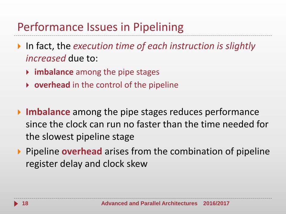
In fact, the execution time of each instruction is slightly increased due to:
imbalance among the pipe stages
overhead in the control of the pipeline
Imbalance among the pipe stages reduces performance since the clock can run no faster than the time needed for the slowest pipeline stage
Pipeline overhead arises from the combination of pipeline register delay and clock skew
2016/2017Advanced and Parallel Architectures18

Example
Assume that an unpipelined processor has a 1 ns clock cycle and that it uses 4 cycles for ALU operations andbranches and 5 cycles for memory operations
Assume that the relative frequencies of these operations are 40%, 20%, and 40%, respectively
Suppose that due to clock skew and setup, pipelining the processor adds 0.2 ns of overhead to the clock
How much speedup in the instruction execution rate will we gain from a pipeline?
2016/2017Advanced and Parallel Architectures19

Example
The average instruction execution time on the unpipelinedprocessor is:
Average instruction execution time =
= Clock cycle × Average CPI =
= 1 ns × [(40% + 20%) × 4 + 40% × 5] =
=1 ns × 4.4 = 4.4 ns
2016/2017Advanced and Parallel Architectures20

Example
In the pipelined implementation, the clock must run at the speed of the slowest stage plus overhead
Average instruction execution time is (1 + 0.2)ns = 1.2 ns
Thus, the speedup from pipelining is
The 0.2 ns overhead establishes a limit on the effectiveness of pipelining
2016/2017Advanced and Parallel Architectures21
times3.7ns1.2
ns4.4
pipelined time ninstructio Average
dunpipeline time ninstructio Average
pipelining from Speedup

Sequential vs Pipelining Execution
2016/2017Advanced and Parallel Architectures22
Time pipe stage = 2 ns
Time 6 pipelined instruction = Time 1 unpipelined instruction + 5 x Time pipe stage = 10 ns + 10 ns = 20 ns
Time N pipelined instruction = Time 1 unpip. instruction + (N-1) x Time pipe stage
10 ns
IF ID EX MEM WB
IF ID EX MEM WB
IF ID EX MEM WB
IF ID EX MEM WB
IF ID EX MEM WB
IF ID EX MEM WB
2 ns
2 ns
2 ns
2 ns
2 ns IF ID EX MEM WB
2 ns
Time 1 unpipelined instruction = 10 ns
Time 6 unpipelined instruction = 60 ns
Time N unpipelined instruction = N x 10 ns

Pipeline Hazards
A hazard (conflict) is created whenever there is a dependence between instructions, and instructions are close enough that the overlap caused by pipelining would change the order of access to the operands involved in the dependence
Hazards:
prevent the next instruction from executing during its clock cycle
reduce the performance from the ideal speedup
2016/2017Advanced and Parallel Architectures23

Pipeline Hazards
There are three classes of hazards:
Structural hazards Attempt to use the same resource from different instructions simultaneously - arise when the hardware cannot support that instructions overlap their execution
Example: Single memory for instructions and data
Data hazards Attempt to use a result before it is ready - arise when an instruction depends on the results of a previous instruction still in the pipeline
Control hazards Attempt to make a decision on the next instruction to execute before the condition is evaluated
Example: conditional branch execution (change the PC)
2016/2017Advanced and Parallel Architectures24

Pipeline Hazards
Hazards in pipelines can make it necessary to stall the pipeline
Some instructions in the pipeline be allowed to proceed while others are delayed
When an instruction is stalled:
all instructions issued later than the stalled instruction—and hence not as far along in the pipeline—are also stalled
Instructions issued earlier than the stalled instruction—and hence farther along in the pipeline—must continue
As a result, no new instructions are fetched during the stall
2016/2017Advanced and Parallel Architectures25

Performance of Pipelines with Stalls
2016/2017Advanced and Parallel Architectures26

Performance of Pipelines with Stalls
2016/2017Advanced and Parallel Architectures27

Performance of Pipelines with Stalls
2016/2017Advanced and Parallel Architectures28
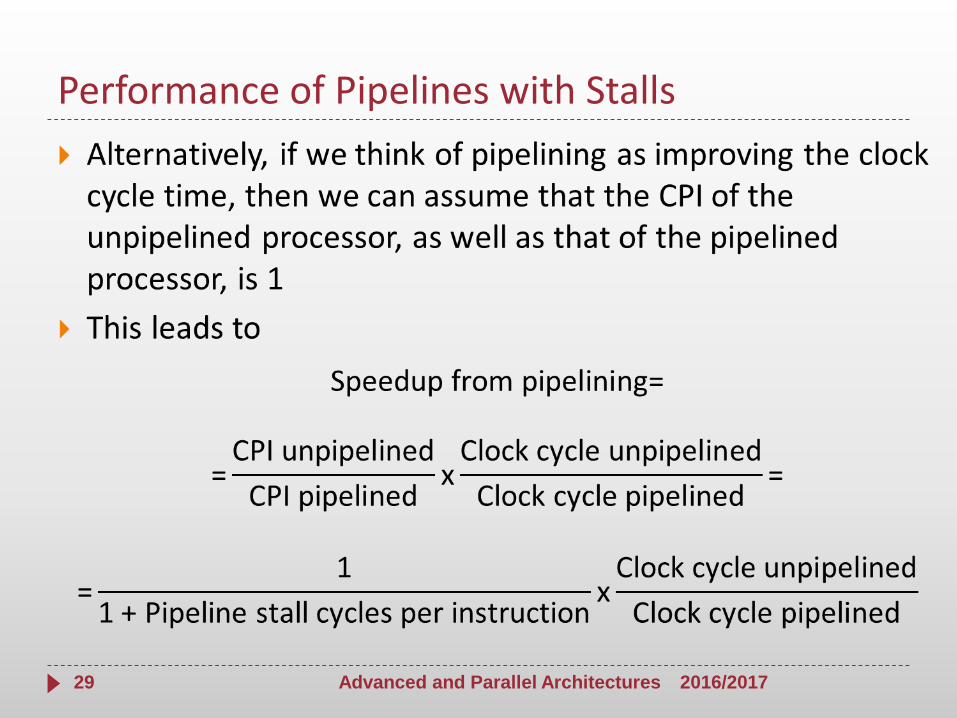
Performance of Pipelines with Stalls
2016/2017Advanced and Parallel Architectures29

Performance of Pipelines with Stalls
2016/2017Advanced and Parallel Architectures30

Performance of Pipelines with Stalls
2016/2017Advanced and Parallel Architectures31

Structural Hazards
When a processor is pipelined, the overlapped execution of instructions requires:
pipelining of functional units, and
duplication of resources
to allow all possible combinations of instructions in the pipeline
If some combination of instructions cannot be accommodated because of resource conflicts, the processor is said to have a structural hazard
2016/2017Advanced and Parallel Architectures32

Structural Hazards
Examples:
Some functional unit is not fully pipelined a sequence of instructions using that unpipelined unit cannot proceed at the rate of one per clock cycle
Some resource has not been duplicated enough to allow all combinations of instructions in the pipeline to execute a processor may have only one register-file write port, but under certain circumstances, the pipeline might want to perform two writes in a clock cycle
Some pipelined processors have shared a single-memory pipeline for data and instructions when an instruction contains a data memory reference, it will conflict with the instruction reference for a later instruction
2016/2017Advanced and Parallel Architectures33

Structural Hazards - single-memory
2016/2017Advanced and Parallel Architectures34
To resolve this hazard, we stall the pipeline for 1 clock cycle when the data memory access occurs

Structural Hazards
Example - Cost of the load structural hazard
Suppose that:
data references constitute 40% of the mix
the ideal CPI of the pipelined processor is 1
Assume that:
the processor with the structural hazard has a clock rate that is 1.05 times higher than the clock rate of the processor without the hazard
Is the pipeline with or without the structural hazard faster, and by how much? (Disregarding any other performance losses)
2016/2017Advanced and Parallel Architectures35

Structural Hazards
Example - Cost of the load structural hazard
A way to solve this problem is to compute the average instruction time on the two processors
The processor without the structural hazard is 1.3 timesfaster
2016/2017Advanced and Parallel Architectures36
ideal
ideal
time cycle Clock1.3
1.05
time cycle Clock1) 0.4 (1
time cycle Clock CPI time ninstructio Average
Structural Hazards
The designer could provide a separate memory access for instructions, either by splitting the cache into separate instruction and data caches or by using a set of buffers, usually called instruction buffers, to hold instructions
A processor without structural hazards has always a lower CPI why would a designer allow structural hazards?
Pipelining all the functional units, or duplicating them, may be too costly
For example, processors that support both an instruction and a data cache access every require twice as much total memory bandwidth and often have higher bandwidth at the pins
2016/2017Advanced and Parallel Architectures37

Data Hazards
Overlapping the execution of instructions introduces data and control hazards
Data hazards occur when the pipeline changes the order of read/write accesses to operands so that the order differs from the order seen by sequentially executing instructions on an unpipelined processor
2016/2017Advanced and Parallel Architectures38

Data Hazards
ADD R1,R2,R3
SUB R4,R1,R5
AND R6,R1,R7
OR R8,R1,R9
XOR R10,R1,R11
All the instructions after the ADD use the result of the ADD instruction
The ADD instruction writes the value of R1 in the WB pipe stage
But the SUB instruction reads the value during its ID stage
This problem is called a data hazard
Unless precautions are taken to prevent it, the SUB instruction will read the wrong value and try to use it
2016/2017Advanced and Parallel Architectures39

Data Hazards
ADD R1,R2,R3
SUB R4,R1,R5
AND R6,R1,R7
OR R8,R1,R9
XOR R10,R1,R11
2016/2017Advanced and Parallel Architectures40
In fact, the value used by the SUB instruction is not even deterministic
If an interrupt should occur between the ADD and SUB instructions, the WB stage of the ADD will complete, and the value of R1 at that point will be the result of the ADD
This unpredictable behavior isunacceptable

Data Hazards
ADD R1,R2,R3
SUB R4,R1,R5
AND R6,R1,R7
OR R8,R1,R9
XOR R10,R1,R11
2016/2017Advanced and Parallel Architectures41
IF ID EX MEM WB
IF ID EX MEM WB
IF ID EX MEM WB
IF ID EX MEM WB
IF ID EX MEM WB

Data Hazards
2016/2017Advanced and Parallel Architectures42
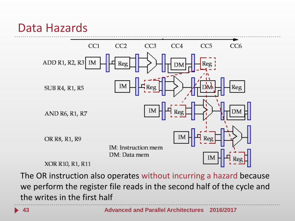
AND instruction is also affected by this hazard: the write of R1 does not complete until the end of clock cycle 5 the AND instruction that reads the registers during clock cycle 4 will receive the wrong results
Data Hazards
2016/2017Advanced and Parallel Architectures43
The OR instruction also operates without incurring a hazard because we perform the register file reads in the second half of the cycle and the writes in the first half

Data Hazards
2016/2017Advanced and Parallel Architectures44
The XOR instruction operates properly because its register read occurs in clock cycle 6, after the register write

Data Hazards: Possible Solutions
Compilation Techniques:
Insertion of nop (no operation) instructions
Instructions scheduling to avoid that correlating instructions are too close
The compiler tries to insert independent instructions among correlating instructions
When the compiler does not find independent instructions, it insert nops
Hardware Techniques:
Insertion of stalls or “bubbles” in the pipeline
Data forwarding or bypassing
2016/2017Advanced and Parallel Architectures45

Insertion of nop
2016/2017Advanced and Parallel Architectures46
ADD R1,R2,R3
nop
nop
nop
SUB R4,R1,R5
AND R6,R1,R7
OR R8,R1,R9
XOR R10,R1,R11
IF ID EX MEM WB
IF ID EX MEM WB
IF ID EX MEM WB
IF ID EX MEM WB
IF ID EX MEM
IF ID EX
IF ID
IF

Scheduling
Example
sub $2, $1, $3
and $12, $2, $5
or $13, $6, $2
add $14, $2, $2
sw $15,100($2)
add $4, $10, $11
and $7, $8, $9
lw $16, 100($18)
sub $2, $1, $3
add $4, $10, $11
and $7, $8, $9
lw $16, 100($18)
and $12, $2, $5
or $13, $6, $2
add $14, $2, $2
sw $15,100($2)
2016/2017Advanced and Parallel Architectures47

Data Hazards Requiring Stalls
Hardware, called pipeline interlock, is added to:
preserve the correct execution pattern
detect a hazard
stall the pipeline until the hazard is cleared
The interlock stalls the pipeline:
beginning with the instruction that wants to use the data until the source instruction produces it
introducing a stall or bubble, as for the structural hazard
The CPI for the stalled instruction increases by the length of the stall
2016/2017Advanced and Parallel Architectures48

Insertion of stalls
2016/2017Advanced and Parallel Architectures49
ADD R1,R2,R3
SUB R4,R1,R5
AND R6,R1,R7
OR R8,R1,R9
XOR R10,R1,R11
IF ID EX MEM WB
ID EX MEM
IF ID EX
IF ID
IF
IF stall stall stall
stall stall stall

Data Hazards Requiring Stalls
Consider the following sequence of instructions:
LD R1,0(R2)
SUB R4,R1,R5
AND R6,R1,R7
OR R8,R1,R9
LD instruction does not have the data until the end of clock cycle 4 (its MEM cycle)
SUB instruction needs to have the data by the beginning of that clock cycle
the data hazard from using the result of a load instruction cannot be completely eliminated with simple hardware
2016/2017Advanced and Parallel Architectures50

Data Hazards Requiring Stalls
Consider the following sequence of instructions:
LD R1,0(R2)
SUB R4,R1,R5
AND R6,R1,R7
OR R8,R1,R9
2016/2017Advanced and Parallel Architectures51

Data Hazards Requiring Stalls
LD R1,0(R2)
SUB R4,R1,R5
AND R6,R1,R7
OR R8,R1,R9
Before stall insertion
LD R1,0(R2)
SUB R4,R1,R5
AND R6,R1,R7
OR R8,R1,R9
After stall insertion
2016/2017Advanced and Parallel Architectures52
IF ID EX MEM WB
EX MEM WB
IF
stall
stall
stall
IF ID
ID EX MEM WB
IF ID EX MEM
IF ID EX MEM WB
IF ID EX MEM WB
IF ID EX MEM WB
IF ID EX MEM WB

Forwarding
Data forwarding (also bypassing or short-circuiting):
Temporary results stored in the pipeline registers instead of waiting for the write back of results in the RF (register file)
A result is forwarded from the pipeline register (output of one unit) to the input of another unit
2016/2017Advanced and Parallel Architectures53

Forwarding
Forwarding works as follows:
The ALU result from both the EX/MEM and MEM/WB pipeline registers is always fed back to the ALU inputs
If the forwarding hardware detects that the previous ALU operation has written the register of a source for the current ALU operation, control logic selects the forwarded result as the ALU input
2016/2017Advanced and Parallel Architectures54

Forwarding
SUB $2, $1, $3
AND $12, $2, $5
OR $13, $6, $2
ADD $14, $2, $2
SW $15,100($2)
2016/2017Advanced and Parallel Architectures55
IF ID EX MEM WB
IF ID EX MEM WB
IF ID EX MEM WB
IF ID EX MEM WB
IF ID EX MEM WB
EX/EXpath
MEM/IDpath
MEM/EXpath

Minimizing Data Hazard Stalls by Forwarding
2016/2017Advanced and Parallel Architectures56

Type of Data Hazards
RAW (READ AFTER WRITE) hazard
instruction n+1 tries to read a source register before the previous instruction n has written it in the RF
Example:
ADD $R1, $R2, $R3
SUB $R4, $R1, $R5
By using forwarding, it is always possible to solve this conflict without introducing stalls, except for the load/use hazards where it is necessary to add one stall
2016/2017Advanced and Parallel Architectures57

Type of Data Hazards
WAW (WRITE AFTER WRITE) hazard
Instruction n+1 tries to write a destination operand before it has been written by the previous instruction n write operations executed in the wrong order (out-of-order)
Example:
LW $R1, 0($R2)
ADD $R1,$R2,$R3
2016/2017Advanced and Parallel Architectures58

Type of Data Hazards
WAR (WRITE AFTER READ) hazard
Instruction n+1 tries to write a destination operand before it has been read from the previous instruction n instruction n reads the wrong value
Example
SW $Y, 0($X) # sw has to read $x
ADDI $X, $X, 4 # addi writes Sx
As before, if we assume the register write in the ALU instructions occurs in the fourth stage and that we need two stages to access the data memory, some instructions could read operands too late in the pipeline
2016/2017Advanced and Parallel Architectures59
Control hazards
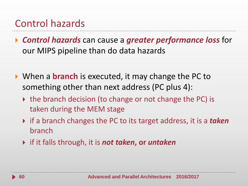
Control hazards can cause a greater performance loss for our MIPS pipeline than do data hazards
When a branch is executed, it may change the PC to something other than next address (PC plus 4):
the branch decision (to change or not change the PC) is taken during the MEM stage
if a branch changes the PC to its target address, it is a takenbranch
if it falls through, it is not taken, or untaken
2016/2017Advanced and Parallel Architectures60

Control hazards
Examples of branches (for MIPS processor):
beq (branch on equal) and bne (branch on not equal)
beq $s1, $s2, L1 # go to L1 if ($s1 == $s2)
bne $s1, $s2, L1 # go to L1 if ($s1 != $s2)
Branch Outcome and Branch Target Address are ready at the end of the EX stage (3th stage)
Conditional branches are solved when PC is updated at the end of the MEM stage (4th stage)
2016/2017Advanced and Parallel Architectures61

Control hazards
Control hazards: Attempt to make a decision on the next instruction to fetch before the branch condition is evaluated
Control hazards arise from the pipelining of conditional branches and other instructions changing the PC
Control hazards reduce the performance from the ideal speedup gained by the pipelining since they can make it necessary to stall the pipeline
2016/2017Advanced and Parallel Architectures62

Example
beq $1, $3, L1
and $12, $2, $5
or $13, $6, $2
add $14, $2, $2
L1: lw $4, 50($7)
The branch instruction may or may not change the PC (MEM stage)
The next 3 instructions are fetched and their execution is started
2016/2017Advanced and Parallel Architectures63
IF ID EX MEM WB
IF ID EX MEM WB
IF ID EX MEM WB
IF ID EX MEM WB
IF ID EX MEM

Example
beq $1, $3, L1
and $12, $2, $5
or $13, $6, $2
add $14, $2, $2
L1: lw $4, 50($7)
If the branch is not taken, the pipeline execution is OK
If the branch is taken, it is necessary to flush the next 3 instructions in the pipeline and fetch the lw instruction at the branch target address (L1)
2016/2017Advanced and Parallel Architectures64
IF ID EX MEM WB
IF ID EX MEM WB
IF ID EX MEM WB
IF ID EX MEM WB
IF ID EX MEM

Solutions
Stalling until resolution: To stall the pipeline until the branch decision is taken and then fetch the correct instruction flow
Without forwarding: for three clock cycles (end MEM stage)
beq $1, $3, L1
and $12, $2, $5
or $13, $6, $2
add $14, $2, $2
Each branch costs three stalls to fetch the correct instruction flow: (PC+4) or Branch Target Address
2016/2017Advanced and Parallel Architectures65
IF ID EX MEM WB
IF ID EX MEM
IF ID EX
IF ID
stall stall stall

Solutions
Stalling until resolution: To stall the pipeline until the branch decision is taken and then fetch the correct instruction flow
With forwarding: for two clock cycles (end EX stage)
beq $1, $3, L1
and $12, $2, $5
or $13, $6, $2
add $14, $2, $2
Each branch costs two stalls to fetch the correct instruction flow: (PC+4) or Branch Target Address
2016/2017Advanced and Parallel Architectures66
IF ID EX MEM WB
IF ID EX MEM
IF ID EX
stall stall IF ID EX MEM WB

Solutions
Early Evaluation of the PC: To improve performance in case of branch hazards, additional hardware resources are needed to to:
Compare registers to derive the Branch Outcome
Compute the Branch Target Address
Update the PC register as soon as possible in the
MIPS processor compares registers, computes branch target address and updates PC during ID stage
2016/2017Advanced and Parallel Architectures67

Solutions
Stalling until resolution at the end of the ID stage
beq $1, $3, L1
and $12, $2, $5
or $13, $6, $2
add $14, $2, $2
Each branch costs one stalls to fetch the correct instruction flow: (PC+4) or Branch Target Address
2016/2017Advanced and Parallel Architectures68
IF ID EX MEM WB
IF ID EX MEM
stall
IF ID EX MEM WB
IF ID EX MEM WB

Solutions
Consequence of early evaluation of the branch decision in ID stage:
In case of add instruction followed by a branch testing the result we need to introduce one stall before ID stage of branch to enable the forwarding (EX-ID) of the result from EX stage of previous instruction
We also need one stall after the branch for branch resolution
addi $1, $1, 4
beq $1, $6, L1
and $12, $2, $5
2016/2017Advanced and Parallel Architectures69
IF ID EX MEM WB
IF ID EX MEM
stallIF ID EX MEM WB
stall
Solutions
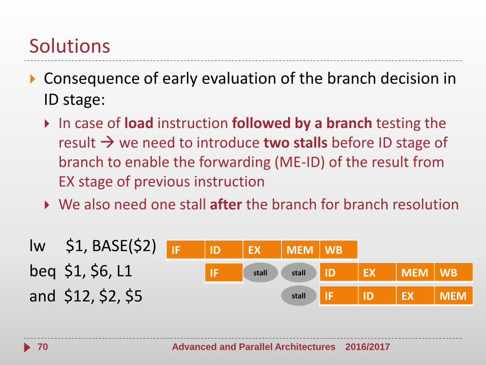
Consequence of early evaluation of the branch decision in ID stage:
In case of load instruction followed by a branch testing the result we need to introduce two stalls before ID stage of branch to enable the forwarding (ME-ID) of the result from EX stage of previous instruction
We also need one stall after the branch for branch resolution
lw $1, BASE($2)
beq $1, $6, L1
and $12, $2, $5
2016/2017Advanced and Parallel Architectures70
IF ID EX MEM WB
IF ID EX MEM
stallIF ID EX MEM WB
stall
stall

Solutions
With the branch decision made during ID stage, there is a reduction of the cost associated with each branch (branch penalty):
We need only one-clock-cycle stall after each branch
Or a flush of only one instruction following the branch
There are techniques to reduce the performance loss
2016/2017Advanced and Parallel Architectures71

Solutions
Branch prediction techniques try to predict ASAP the outcome of a branch instruction
Static Branch Prediction Techniques: The actions for a branch are fixed for each branch during the entire execution. The actions are fixed at compile time
Branch Always Not Taken (Predicted-Not-Taken)
Branch Always Taken (Predicted-Taken)
Backward Taken Forward Not Taken (BTFNT)
Profile-Driven Prediction
Delayed Branch
2016/2017Advanced and Parallel Architectures72

Solutions
Branch prediction techniques try to predict ASAP the outcome of a branch instruction
Dynamic Branch Prediction Techniques: The decision causing the branch prediction can dynamically change during the program execution
Basic Idea: To use the past branch behavior to predict
We use hardware to dynamically predict the outcome of a branch: the prediction will depend on the behavior of the branch at run time and will change if the branch changes its behavior during execution
2016/2017Advanced and Parallel Architectures73
Exercise - Midterm 2014/2015
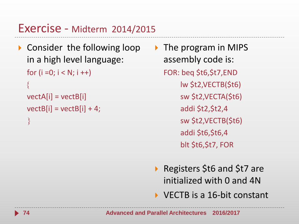
Consider the following loop in a high level language:
for (i =0; i < N; i ++)
vectA[i] = vectB[i]
vectB[i] = vectB[i] + 4;
The program in MIPS assembly code is:
FOR: beq $t6,$t7,END
lw $t2,VECTB($t6)
sw $t2,VECTA($t6)
addi $t2,$t2,4
sw $t2,VECTB($t6)
addi $t6,$t6,4
blt $t6,$t7, FOR
Registers $t6 and $t7 are initialized with 0 and 4N
VECTB is a 16-bit constant
2016/2017Advanced and Parallel Architectures74

Exercise
Let us consider the loop executed by 5-stage pipelined MIPS processor WITHOUT any optimisation in the pipeline:
Identify the Hazard Type (Data Hazard or Control Hazard)
Identify the number of stalls to be inserted before each instruction (or between stages IF and ID of each instruction) to solve the hazards
For each hazard, add an ARROW to indicate the pipeline stages involved in the hazard
2016/2017Advanced and Parallel Architectures75
Num.
StallsINSTRUCTION C1 C2 C3 C4 C5 C7 C6 C8 C9 C10 C11
Hazard
Type
FOR: beq $t6,$t7,END IF ID EX ME WB
lw $t2,VECTB($t6) IF ID EX ME WB
sw $t2,VECTA($t6) IF ID EX ME WB
addi $t2,$t2,4 IF ID EX ME WB
sw $t2,VECTB($t6) IF ID EX ME WB
addi $t6,$t6,4 IF ID EX ME WB
blt $t6,$t7, FOR IF ID EX ME WB

Exercise
Let us consider the loop executed by 5-stage pipelined MIPS processor WITHOUT any optimisation in the pipeline:
Identify the Hazard Type (Data Hazard or Control Hazard)
Identify the number of stalls to be inserted before each instruction (or between stages IF and ID of each instruction) to solve the hazards
For each hazard, add an ARROW to indicate the pipeline stages involved in the hazard
2016/2017Advanced and Parallel Architectures76
Num.
StallsINSTRUCTION C1 C2 C3 C4 C5 C7 C6 C8 C9 C10 C11
Hazard
Type
FOR: beq $t6,$t7,END IF ID EX ME WB
3 lw $t2,VECTB($t6) IF ID EX ME WB CNTR
sw $t2,VECTA($t6) IF ID EX ME WB
addi $t2,$t2,4 IF ID EX ME WB
sw $t2,VECTB($t6) IF ID EX ME WB
addi $t6,$t6,4 IF ID EX ME WB
blt $t6,$t7, FOR IF ID EX ME WB

Exercise
Let us consider the loop executed by 5-stage pipelined MIPS processor WITHOUT any optimisation in the pipeline:
Identify the Hazard Type (Data Hazard or Control Hazard)
Identify the number of stalls to be inserted before each instruction (or between stages IF and ID of each instruction) to solve the hazards
For each hazard, add an ARROW to indicate the pipeline stages involved in the hazard
2016/2017Advanced and Parallel Architectures77
Num.
StallsINSTRUCTION C1 C2 C3 C4 C5 C7 C6 C8 C9 C10 C11
Hazard
Type
FOR: beq $t6,$t7,END IF ID EX ME WB
3 lw $t2,VECTB($t6) IF ID EX ME WB CNTR
3 sw $t2,VECTA($t6) IF ID EX ME WB DATA
2 addi $t2,$t2,4 IF ID EX ME WB DATA
sw $t2,VECTB($t6) IF ID EX ME WB
addi $t6,$t6,4 IF ID EX ME WB
blt $t6,$t7, FOR IF ID EX ME WB

Exercise
Let us consider the loop executed by 5-stage pipelined MIPS processor WITHOUT any optimisation in the pipeline:
Identify the Hazard Type (Data Hazard or Control Hazard)
Identify the number of stalls to be inserted before each instruction (or between stages IF and ID of each instruction) to solve the hazards
For each hazard, add an ARROW to indicate the pipeline stages involved in the hazard
2016/2017Advanced and Parallel Architectures78
Num.
StallsINSTRUCTION C1 C2 C3 C4 C5 C7 C6 C8 C9 C10 C11
Hazard
Type
FOR: beq $t6,$t7,END IF ID EX ME WB
3 lw $t2,VECTB($t6) IF ID EX ME WB CNTR
3 sw $t2,VECTA($t6) IF ID EX ME WB DATA
2 addi $t2,$t2,4 IF ID EX ME WB DATA
3 sw $t2,VECTB($t6) IF ID EX ME WB DATA
addi $t6,$t6,4 IF ID EX ME WB
blt $t6,$t7, FOR IF ID EX ME WB

Exercise
Let us consider the loop executed by 5-stage pipelined MIPS processor WITHOUT any optimisation in the pipeline:
Identify the Hazard Type (Data Hazard or Control Hazard)
Identify the number of stalls to be inserted before each instruction (or between stages IF and ID of each instruction) to solve the hazards
For each hazard, add an ARROW to indicate the pipeline stages involved in the hazard
2016/2017Advanced and Parallel Architectures79
Num.
StallsINSTRUCTION C1 C2 C3 C4 C5 C7 C6 C8 C9 C10 C11
Hazard
Type
FOR: beq $t6,$t7,END IF ID EX ME WB
3 lw $t2,VECTB($t6) IF ID EX ME WB CNTR
3 sw $t2,VECTA($t6) IF ID EX ME WB DATA
2 addi $t2,$t2,4 IF ID EX ME WB DATA
3 sw $t2,VECTB($t6) IF ID EX ME WB DATA
addi $t6,$t6,4 IF ID EX ME WB
3 blt $t6,$t7, FOR IF ID EX ME WB DATA

Exercise
Let us consider the loop executed by 5-stage pipelined MIPS processor WITHOUT any optimisation in the pipeline:
Identify the Hazard Type (Data Hazard or Control Hazard)
Identify the number of stalls to be inserted before each instruction (or between stages IF and ID of each instruction) to solve the hazards
For each hazard, add an ARROW to indicate the pipeline stages involved in the hazard
2016/2017Advanced and Parallel Architectures80
Num.
StallsINSTRUCTION C1 C2 C3 C4 C5 C7 C6 C8 C9 C10 C11
Hazard
Type
3 FOR: beq $t6,$t7,END IF ID EX ME WB CNTR
3 lw $t2,VECTB($t6) IF ID EX ME WB CNTR
3 sw $t2,VECTA($t6) IF ID EX ME WB DATA
2 addi $t2,$t2,4 IF ID EX ME WB DATA
3 sw $t2,VECTB($t6) IF ID EX ME WB DATA
addi $t6,$t6,4 IF ID EX ME WB
3 blt $t6,$t7, FOR IF ID EX ME WB DATA

Exercise
For each instruction
Write the phases and insert the stalls to solve the hazards identified take into account that solving some hazards can help to solve those that follow
Specify the number of stalls actually inserted
2016/201781
Num.
StallsINSTRUCTION C1 C2 C3 C4 C5 C7 C6 C8 C9 C10 C11 C12 C13 C14 C15 C16 C17 C18 C19 C20 C21 C22 C23 C24
FOR: beq $t6,$t7,END
lw $t2,VECTB($t6)
sw $t2,VECTA($t6)
addi $t2,$t2,4
sw $t2,VECTB($t6)
addi $t6,$t6,4
blt $t6,$t7, FOR

Exercise
For each instruction
Write the phases and insert the stalls to solve the hazards identified take into account that solving some hazards can help to solve those that follow
Specify the number of stalls actually inserted
2016/201782
Num.
StallsINSTRUCTION C1 C2 C3 C4 C5 C7 C6 C8 C9 C10 C11 C12 C13 C14 C15 C16 C17 C18 C19 C20 C21 C22 C23 C24
FOR: beq $t6,$t7,END IF ID EX ME WB
3 lw $t2,VECTB($t6)
sw $t2,VECTA($t6)
addi $t2,$t2,4
sw $t2,VECTB($t6)
addi $t6,$t6,4
blt $t6,$t7, FOR
Num.
StallsINSTRUCTION C1 C2 C3 C4 C5 C7 C6 C8 C9 C10 C11
Hazard
Type
3 FOR: beq $t6,$t7,END IF ID EX ME WB CNTR
3 lw $t2,VECTB($t6) IF ID EX ME WB CNTR
3 sw $t2,VECTA($t6) IF ID EX ME WB DATA
2 addi $t2,$t2,4 IF ID EX ME WB DATA
3 sw $t2,VECTB($t6) IF ID EX ME WB DATA
addi $t6,$t6,4 IF ID EX ME WB
3 blt $t6,$t7, FOR IF ID EX ME WB DATA
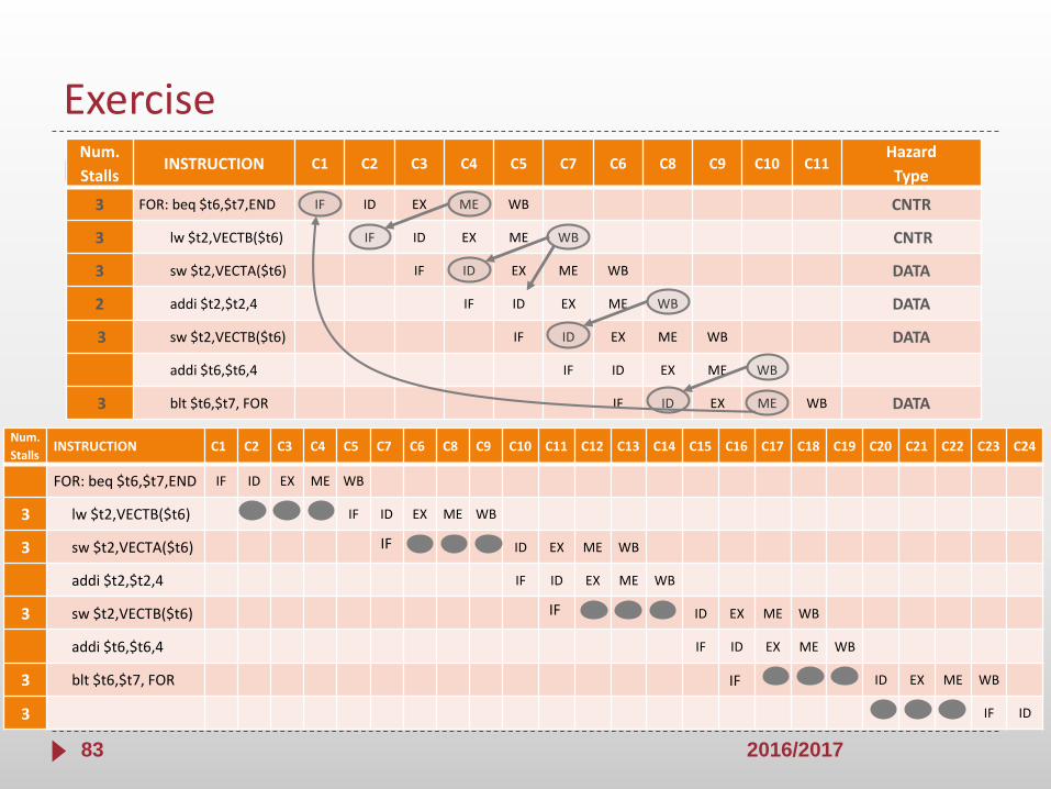
Exercise
For each instruction
Write the phases and insert the stalls to solve the hazards identified take into account that solving some hazards can help to solve those that follow
Specify the number of stalls actually inserted
2016/201783
Num.
StallsINSTRUCTION C1 C2 C3 C4 C5 C7 C6 C8 C9 C10 C11 C12 C13 C14 C15 C16 C17 C18 C19 C20 C21 C22 C23 C24
FOR: beq $t6,$t7,END IF ID EX ME WB
3 lw $t2,VECTB($t6) IF ID EX ME WB
3 sw $t2,VECTA($t6) IF ID EX ME WB
addi $t2,$t2,4 IF ID EX ME WB
3 sw $t2,VECTB($t6) IF ID EX ME WB
addi $t6,$t6,4 IF ID EX ME WB
3 blt $t6,$t7, FOR IF ID EX ME WB
3 IF ID
Num.
StallsINSTRUCTION C1 C2 C3 C4 C5 C7 C6 C8 C9 C10 C11
Hazard
Type
3 FOR: beq $t6,$t7,END IF ID EX ME WB CNTR
3 lw $t2,VECTB($t6) IF ID EX ME WB CNTR
3 sw $t2,VECTA($t6) IF ID EX ME WB DATA
2 addi $t2,$t2,4 IF ID EX ME WB DATA
3 sw $t2,VECTB($t6) IF ID EX ME WB DATA
addi $t6,$t6,4 IF ID EX ME WB
3 blt $t6,$t7, FOR IF ID EX ME WB DATA


![Pipelining & Parallel Processing - ics.kaist.ac.krics.kaist.ac.kr/ee878_2018f/[EE878]3 Pipelining and Parallel Processing.pdf · Pipelining processing By using pipelining latches](https://static.fdocuments.net/doc/165x107/5d40e26d88c99391748d47fb/pipelining-parallel-processing-icskaistackricskaistackree8782018fee8783.jpg)