ADVANCED MULTIPLE IN-MULTIPLE OUT (MIMO) ANTENNA ... · advanced multiple in-multiple out (mimo)...
66
ADVANCED MULTIPLE IN-MULTIPLE OUT (MIMO) ANTENNA COMMUNICATIONS FOR AIRBORNE NETWORKS SYRACUSE UNIVERSITY MARCH 2015 FINAL TECHNICAL REPORT APPROVED FOR PUBLIC RELEASE; DISTRIBUTION UNLIMITED STINFO COPY AIR FORCE RESEARCH LABORATORY INFORMATION DIRECTORATE AFRL-RI-RS-TR-2015-061 UNITED STATES AIR FORCE ROME, NY 13441 AIR FORCE MATERIEL COMMAND
Transcript of ADVANCED MULTIPLE IN-MULTIPLE OUT (MIMO) ANTENNA ... · advanced multiple in-multiple out (mimo)...

ADVANCED MULTIPLE IN-MULTIPLE OUT (MIMO) ANTENNA COMMUNICATIONS FOR AIRBORNE NETWORKS
SYRACUSE UNIVERSITY
MARCH 2015
FINAL TECHNICAL REPORT
APPROVED FOR PUBLIC RELEASE; DISTRIBUTION UNLIMITED
STINFO COPY
AIR FORCE RESEARCH LABORATORY INFORMATION DIRECTORATE
AFRL-RI-RS-TR-2015-061
UNITED STATES AIR FORCE ROME, NY 13441 AIR FORCE MATERIEL COMMAND
NOTICE AND SIGNATURE PAGE
Using Government drawings, specifications, or other data included in this document for any purpose other than Government procurement does not in any way obligate the U.S. Government. The fact that the Government formulated or supplied the drawings, specifications, or other data does not license the holder or any other person or corporation; or convey any rights or permission to manufacture, use, or sell any patented invention that may relate to them.
This report is the result of contracted fundamental research deemed exempt from public affairs security and policy review in accordance with SAF/AQR memorandum dated 10 Dec 08 and AFRL/CA policy clarification memorandum dated 16 Jan 09. This report is available to the general public, including foreign nationals. Copies may be obtained from the Defense Technical Information Center (DTIC) (http://www.dtic.mil).
AFRL-RI-RS-TR-2015-061 HAS BEEN REVIEWED AND IS APPROVED FOR PUBLICATION IN ACCORDANCE WITH ASSIGNED DISTRIBUTION STATEMENT.
FOR THE DIRECTOR:
/ S / / S / PAUL J. OLESKI MARK H. LINDERMAN Work Unit Manager Technical Advisor, Computing
& Communications Division Information Directorate
This report is published in the interest of scientific and technical information exchange, and its publication does not constitute the Government’s approval or disapproval of its ideas or findings.
REPORT DOCUMENTATION PAGE Form Approved OMB No. 0704-0188
The public reporting burden for this collection of information is estimated to average 1 hour per response, including the time for reviewing instructions, searching existing data sources, gathering and maintaining the data needed, and completing and reviewing the collection of information. Send comments regarding this burden estimate or any other aspect of this collection of information, including suggestions for reducing this burden, to Department of Defense, Washington Headquarters Services, Directorate for Information Operations and Reports (0704-0188), 1215 Jefferson Davis Highway, Suite 1204, Arlington, VA 22202-4302. Respondents should be aware that notwithstanding any other provision of law, no person shall be subject to any penalty for failing to comply with a collection of information if it does not display a currently valid OMB control number. PLEASE DO NOT RETURN YOUR FORM TO THE ABOVE ADDRESS. 1. REPORT DATE (DD-MM-YYYY)
MAR 2015 2. REPORT TYPE
FINAL TECHNICAL REPORT 3. DATES COVERED (From - To)
OCT 2011 – SEP 2014 4. TITLE AND SUBTITLE
ADVANCED MULTIPLE IN-MULTIPLE OUT (MIMO) ANTENNA COMMUNICATIONS FOR AIRBORNE NETWORKS
5a. CONTRACT NUMBER FA8750-11-1-0040
5b. GRANT NUMBER N/A
5c. PROGRAM ELEMENT NUMBER 62788F
6. AUTHOR(S)
Biao Chen
5d. PROJECT NUMBER MIMO
5e. TASK NUMBER TE
5f. WORK UNIT NUMBER CH
7. PERFORMING ORGANIZATION NAME(S) AND ADDRESS(ES)Syracuse University 900 South Crouse Ave Syracuse NY 13244
8. PERFORMING ORGANIZATIONREPORT NUMBER
9. SPONSORING/MONITORING AGENCY NAME(S) AND ADDRESS(ES)
Air Force Research Laboratory/RITE525 Brooks Road Rome NY 13441-4505
10. SPONSOR/MONITOR'S ACRONYM(S)
AFRL/RI 11. SPONSOR/MONITOR’S REPORT NUMBER
AFRL-RI-RS-TR-2015-061 12. DISTRIBUTION AVAILABILITY STATEMENTApproved for Public Release; Distribution Unlimited. This report is the result of contracted fundamental research deemed exempt from public affairs security and policy review in accordance with SAF/AQR memorandum dated 10 Dec 08 and AFRL/CA policy clarification memorandum dated 16 Jan 09. 13. SUPPLEMENTARY NOTES
14. ABSTRACTThe objective of this project was to study and implement a MIMO architecture in airborne communications. The primary challenges include: 1) the lack of scatters in airborne communications which often renders the channel matrices to be rank deficient; 2) fast channel variation due to high mobility of the communication platforms. Toward overcoming these challenges and in close collaboration with AFRL/RITE researchers, we have: - explored the feasibility of channel tracking in a dynamic channel environment - developed a GUI system that allows one to visualize the effective capacity under various communications scenarios - developed a D-BLAST architecture that employs orthogonal spreading to counter the effect of channel rank deficiency - implemented, using python and with four USRP N210 nodes, a 2x2 MIMO system with over the air transmission.
15. SUBJECT TERMSMultiple In-Multiple Out (MIMO Antenna Communications, Airborne Networks, D-BLAST, channel tracking, USRP N210 nodes
16. SECURITY CLASSIFICATION OF: 17. LIMITATION OF ABSTRACT
UU
18. NUMBEROF PAGES
19a. NAME OF RESPONSIBLE PERSON PAUL J. OLESKI
a. REPORTU
b. ABSTRACTU
c. THIS PAGEU
19b. TELEPHONE NUMBER (Include area code) N/A
Standard Form 298 (Rev. 8-98) Prescribed by ANSI Std. Z39.18
66
Contents
List of Figures iii
List of Tables iv
1 Summary 1
2 Introduction 32.1 Channel Tracking . . . . . . . . . . . . . . . . . . . . . . . . . . . . . . . . . 32.2 Variable Rate MIMO . . . . . . . . . . . . . . . . . . . . . . . . . . . . . . . 42.3 GNU Radio MIMO Implementation Using USRP N210 . . . . . . . . . . . . 42.4 Organization . . . . . . . . . . . . . . . . . . . . . . . . . . . . . . . . . . . 4
3 Channel Tracking 63.1 Introduction . . . . . . . . . . . . . . . . . . . . . . . . . . . . . . . . . . . . 63.2 Methods, Assumptions and Procedures . . . . . . . . . . . . . . . . . . . . . 6
3.2.1 Channel Estimation - Optimal Length . . . . . . . . . . . . . . . . . 63.2.2 D-BLAST Architecture . . . . . . . . . . . . . . . . . . . . . . . . . . 103.2.3 Channel Tracking . . . . . . . . . . . . . . . . . . . . . . . . . . . . . 11
3.3 Results and Discussion . . . . . . . . . . . . . . . . . . . . . . . . . . . . . . 123.3.1 Channel Tracking . . . . . . . . . . . . . . . . . . . . . . . . . . . . . 123.3.2 Outage Detection . . . . . . . . . . . . . . . . . . . . . . . . . . . . . 13
3.4 Channel Tracking Simulator . . . . . . . . . . . . . . . . . . . . . . . . . . . 133.4.1 Component Description . . . . . . . . . . . . . . . . . . . . . . . . . 13
3.5 Conclusion . . . . . . . . . . . . . . . . . . . . . . . . . . . . . . . . . . . . . 15
4 Variable Rate MIMO 174.1 Introduction . . . . . . . . . . . . . . . . . . . . . . . . . . . . . . . . . . . . 174.2 Methods, Assumptions and Procedures . . . . . . . . . . . . . . . . . . . . . 18
4.2.1 MIMO Channel State Matrix Measurements . . . . . . . . . . . . . . 184.2.2 Variable Rate MIMO . . . . . . . . . . . . . . . . . . . . . . . . . . . 21
4.3 Results and Discussion . . . . . . . . . . . . . . . . . . . . . . . . . . . . . . 224.4 Conclusion . . . . . . . . . . . . . . . . . . . . . . . . . . . . . . . . . . . . . 24
5 GnuRadio MIMO Implementation Using USRP N210 255.1 Introduction . . . . . . . . . . . . . . . . . . . . . . . . . . . . . . . . . . . . 255.2 Methods, Assumptions and Procedures . . . . . . . . . . . . . . . . . . . . . 25
i
5.2.1 System Overview . . . . . . . . . . . . . . . . . . . . . . . . . . . . . 255.2.2 C++ MIMO Library . . . . . . . . . . . . . . . . . . . . . . . . . . . 26
5.3 Results and Discussion . . . . . . . . . . . . . . . . . . . . . . . . . . . . . . 26
6 Conclusion 28
References 29
Symbols, Abbreviations and Acronyms 31
Appendices 33
A Proof of Theorem 1 34
B C++ Library Reference 37
ii
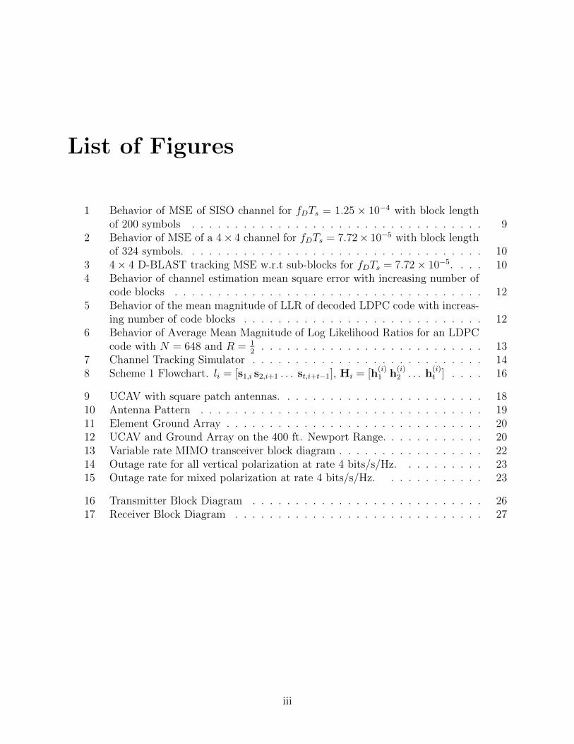
List of Figures
1 Behavior of MSE of SISO channel for fDTs = 1.25 × 10⁻⁴ with block lengthof 200 symbols . . . . . . . . . . . . . . . . . . . . . . . . . . . . . . . . . . 9
2 Behavior of MSE of a 4× 4 channel for fDTs = 7.72× 10⁻⁵ with block lengthof 324 symbols. . . . . . . . . . . . . . . . . . . . . . . . . . . . . . . . . . . 10
3 4× 4 D-BLAST tracking MSE w.r.t sub-blocks for fDTs = 7.72× 10⁻⁵. . . . 104 Behavior of channel estimation mean square error with increasing number of
code blocks . . . . . . . . . . . . . . . . . . . . . . . . . . . . . . . . . . . . 125 Behavior of the mean magnitude of LLR of decoded LDPC code with increas-
ing number of code blocks . . . . . . . . . . . . . . . . . . . . . . . . . . . . 126 Behavior of Average Mean Magnitude of Log Likelihood Ratios for an LDPC
code with N = 648 and R = 12
. . . . . . . . . . . . . . . . . . . . . . . . . . 137 Channel Tracking Simulator . . . . . . . . . . . . . . . . . . . . . . . . . . . 148 Scheme 1 Flowchart. li = [s1,i s2,i+1 . . . st,i+t−1], Hi = [h
(i)1 h
(i)2 . . . h
(i)t ] . . . . 16
9 UCAV with square patch antennas. . . . . . . . . . . . . . . . . . . . . . . . 1810 Antenna Pattern . . . . . . . . . . . . . . . . . . . . . . . . . . . . . . . . . 1911 Element Ground Array . . . . . . . . . . . . . . . . . . . . . . . . . . . . . . 2012 UCAV and Ground Array on the 400 ft. Newport Range. . . . . . . . . . . . 2013 Variable rate MIMO transceiver block diagram . . . . . . . . . . . . . . . . . 2214 Outage rate for all vertical polarization at rate 4 bits/s/Hz. . . . . . . . . . 2315 Outage rate for mixed polarization at rate 4 bits/s/Hz. . . . . . . . . . . . 23
16 Transmitter Block Diagram . . . . . . . . . . . . . . . . . . . . . . . . . . . 2617 Receiver Block Diagram . . . . . . . . . . . . . . . . . . . . . . . . . . . . . 27
iii
List of Tables
1 Symbol Space-Time Diagram . . . . . . . . . . . . . . . . . . . . . . . . . . 11
iv
Summary
This report summarizes the results of the research and development effort under the auspiceof AFRL Award ]FA8750-11-1-0040. The primary objective of the project is to study andimplement MIMO architecture in airborne communications. The primary challenges include1) the lack of scatterers in airborne communications which often renders the channel matricesto be rank deficient; 2) fast channel variation due to high mobility of the communicationplatforms.
Toward overcoming these challenges and in close collaboration with AFRL researchers,we have
• explored the feasibility of channel tracking in a dynamic channel environment;
• developed a GUI system that allows one to visualize the effective capacity under variouscommunication scenarios;
• developed a D-BLAST architecture that employs orthogonal spreading to counter theeffect of channel rank deficiency;
• implemented, using python and with four USRP N210 [1] nodes, a 2×2 MIMO systemwith over the air transmission.
The following refereed articles have been published under this effort:
• K. Borle, B. Chen, and M. J. Gans, Channel tracking for D-BLAST for airborneplatforms, Proc. Asilomar Conference on Signals, Systems, and Computers, Monterey,CA, Nov. 2011
• M. J. Gans, K. Borle, B. Chen, T. Freeland, D. McCarthy, R. Nelson, D. Overrockerand P. Oleski, Enhancing connectivity of unmanned vehicles through MIMO communi-cations, Proc. of IEEE Vehicular Technology Conference, Las Vegas, NV, Sept. 2013.
In addition, various software packages have been delivered to the AFRL collaborators,including
• Channel tracker simulator, as described in Chapter 3.
1APPROVED FOR PUBLIC RELEASE; DISTRIBUTION UNLIMITED

• Channel matrix simulator. This is to take the Newport measurement data and con-struct a new channel matrix according to the relative position of the transmitter andreceiver through extrapolation.
• LDPC encoder and decoder source code.
• C++ code for the MIMO D-BLAST transmitter and receiver blocks.
2APPROVED FOR PUBLIC RELEASE; DISTRIBUTION UNLIMITED
Introduction
A point to point airborne MIMO communication link can be defined as two terminals com-municating over a wireless channel such that either one or both the terminals are airborneand both employ multiple antennas. On the other hand, the conventionally studied MIMOwireless communication is based on the premise that the communicating multi-antenna ter-minals are located in a dense urban environment. Two important factors distinguish such anairborne MIMO channel from a conventional MIMO channel: Firstly, the channel conditionschange very rapidly in an airborne link due to fast relative motion between the airborne ter-minals. Secondly, the channel offers a significantly less scattering environment as comparedto a dense urban environment. As such, airborne MIMO communication poses a somewhatdifferent set of problems as compared to the conventional MIMO communication problems.
This report describes our efforts in addressing the above mentioned problems of airborneMIMO communication. To be precise we address the problems of channel tracking in dy-namic channel conditions and communication over rank deficient channels. In addressingthese problems, we have encountered D-BLAST transceiver architecture as the central idea,upon which our proposed solutions are based. Hence, to facilitate experiments, we also de-velop a GNU Radio/USRP based D-BLAST communication system employing 2 transmitand 2 receive antennas. Furthermore we have developed a C++ library that provides D-BLAST encoding and decoding functionality. The C++ library is not coupled to the GNURadio framework and hence provides more flexibility in its usage.
In the following we provide a brief description of the contributions followed by the orga-nization of the report.
2.1 Channel Tracking
The channel in airborne communication changes continuously at a rapid rate. To facilitatecoherent symbol detection in such a rapidly changing channel, the receiver needs to updatethe channel state information at a much more frequent rate. The traditional use of embedding pilot symbols with payload data may not be easy to justify if channelvariation is fast and/or data rate requirement is high. We consider the implementationof D-BLAST for airborne platforms and develop channel tracking scheme to eliminate orreduce the use of pilot symbols. In a normal operation mode, channel update isachieved dynamically as
3APPROVED FOR PUBLIC RELEASE; DISTRIBUTION UNLIMITED
each layer of the D-BLAST, encoded using an LDPC code, is decoded. To ensure thatthe transceiver can detect outage due to the loss of channel state, an adaptive algorithm isdevised utilizing the extremal property of terminating likelihood ratio of an LDPC decoder.
2.2 Variable Rate MIMO
In this part of the report we develop a variable rate MIMO scheme, based on D-BLASTtransceiver architecture, to overcome MIMO channels that are rank deficient. Real channelmeasurements are conducted and the analysis supports the use of MIMO communications forsuch applications due to its potential throughput advantage. Unique challenges and the waysto address them are described in detail. In particular, the lack of scattering and the blockageof line of sight may lead to rank deficient channel matrices, which are exacerbated due tothe absence of channel state information at the transmitter. A variable rate MIMO schemeis thus proposed to overcome these challenges in order to realize the promising throughputgain afforded by MIMO communication.
2.3 GNU Radio MIMO Implementation Using USRP
N210
An indispensable part of any scientific inquiry is its experimental component. The afore-mentioned Variable Rate MIMO scheme shows promising results for the rank deficient chan-nels obtained through real measurement data. The results, as encouraging as they appear,nonetheless must be validated through experimental means. Therefore, to conduct real-timewireless experiments we need a platform that facilitates efficient and fast prototyping of atestbed. Software defined radio, which provides us with these desirable traits, appears as avery attractive option for developing the necessary components required for the experimen-tation.
The GNU Radio software development toolkit combined with USRPs provide an effi-cient and rapidly employable software defined radio system. Using the GNU Radio/USRPplatform, we have developed a 2 × 2 D-BLAST transceiver. We have also created a C++library, developed separately from the GNU Radio based testing framework but able to beused within the framework.
2.4 Organization
The rest of the report is organized as follows.
• Chapter 3 develops and analyzes the channel tracking scheme for a D-BLAST basedairborne communication system.
• Chapter 4 develops a variable rate MIMO scheme, based on D-BLAST transceiverarchitecture, to overcome MIMO channels that are rank deficient.
4APPROVED FOR PUBLIC RELEASE; DISTRIBUTION UNLIMITED

• Chapter 5 provides a brief overview of the C++ based software library which is devel-oped to facilitate experimentation of MIMO communication.
• Chapter 6 concludes the report.
5APPROVED FOR PUBLIC RELEASE; DISTRIBUTION UNLIMITED
Channel Tracking
3.1 Introduction
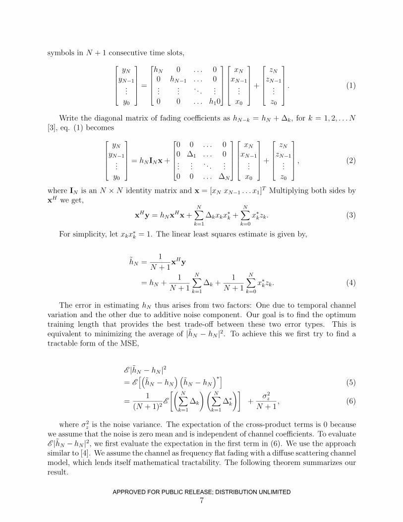
For a communication system in which either one or both the stations are in motion, thechannel is continuously changing. At the receiver end, for coherent detection of symbols,this translates to constant updating of channel state information. The conventional methodis to multiplex pilots and data symbols. For the case where there is rapid variation inchannel, this pilot overhead may not be affordable. In order to tackle this scenario we tryto investigate the case in which we use previously detected symbols to estimate channel fornext block.
Since, the channel varies temporally, simply using the previous block of decoded symbolsmay not be optimal. We try to solve this problem by first finding the optimal length of symbols needed to minimize the mean square error of estimated channel for a SISO channelwith rayleigh fading. Then we generalize this to MIMO case.
Once we know how to track the channel efficiently, the question arises, how to detectoutage at the receiver. We narrow down our search for an outage detection scheme to systemswhich use LDPC codes. We find through simulations that the average mean magnitude ofthe log liklihood ratios remain small when the codeword is docoded incorrectly, while in theotherwise case, the mean magnitude has a high value.
Section 3.2.1 gives the analysis for optimal length to minimize the mean squared error ina Rayleigh fading channel. We then give a brief description of the D-BLAST architecture inSection 3.2.2. Section 3.2.3 describes the channel tracking algorithm for D-BLAST, followedby simulation results. Section 3.4 briefly describes the channel tracking simulator, which wehave developed.
3.2 Methods, Assumptions and Procedures
3.2.1 Channel Estimation - Optimal Length
Single Input Single Output Case
Consider a SISO channel, yi = hixi+zi, where xi is the transmitted symbol, zi is the additivenoise and hi is the fading coefficient in the ith time slot [2]. If the transmitter transmits N+1
6APPROVED FOR PUBLIC RELEASE; DISTRIBUTION UNLIMITED
symbols in N + 1 consecutive time slots,yNyN−1
...y0
=
hN 0 . . . 00 hN−1 . . . 0...
.... . .
...0 0 . . . h10
xNxN−1
...x0
+
zNzN−1
...z0
. (1)
Write the diagonal matrix of fading coefficients as hN−k = hN + ∆k, for k = 1, 2, . . . N[3], eq. (1) becomes
yNyN−1
...y0
= hNINx +
0 0 . . . 00 ∆1 . . . 0...
.... . .
...0 0 . . . ∆N
xNxN−1
...x0
+
zNzN−1
...z0
, (2)
where IN is an N ×N identity matrix and x = [xN xN−1 . . . x1]T Multiplying both sides by
xH we get,
xHy = hNxHx +N∑k=1
∆kxkx∗k +
N∑k=0
x∗kzk. (3)
For simplicity, let xkx∗k = 1. The linear least squares estimate is given by,
hN =1
N + 1xHy
= hN +1
N + 1
N∑k=1
∆k +1
N + 1
N∑k=0
x∗kzk. (4)
The error in estimating hN thus arises from two factors: One due to temporal channelvariation and the other due to additive noise component. Our goal is to find the optimumtraining length that provides the best trade-off between these two error types. This isequivalent to minimizing the average of |hN − hN |2. To achieve this we first try to find atractable form of the MSE,
E |hN − hN |2
= E[(hN − hN
) (hN − hN
)∗](5)
=1
(N + 1)2E
[(N∑k=1
∆k
)(N∑k=1
∆∗k
)]+
σ2z
N + 1, (6)
where σ2z is the noise variance. The expectation of the cross-product terms is 0 because
we assume that the noise is zero mean and is independent of channel coefficients. To evaluateE |hN − hN |2, we first evaluate the expectation in the first term in (6). We use the approachsimilar to [4]. We assume the channel as frequency flat fading with a diffuse scattering channelmodel, which lends itself mathematical tractability. The following theorem summarizes ourresult.
7APPROVED FOR PUBLIC RELEASE; DISTRIBUTION UNLIMITED
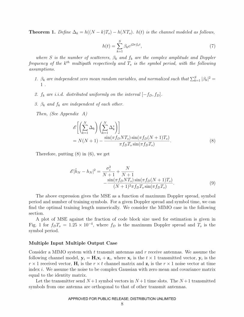
Theorem 1. Define ∆k = h((N − k)Ts)− h(NTs). h(t) is the channel modeled as follows,
h(t) =S∑k=1
βkej2πfkt, (7)
where S is the number of scatterers, βk and fk are the complex amplitude and Dopplerfrequency of the kth multipath respectively and Ts is the symbol period, with the followingassumptions.
1. βk are independent zero mean random variables, and normalized such that∑Sk=1 |βk|2 =
1 .
2. fk are i.i.d. distributed uniformly on the interval [−fD, fD].
3. βk and fk are independent of each other.
Then, (See Appendix A)
E
[(N∑k=1
∆k
)(N∑k=1
∆∗k
)]
= N(N + 1)− sin(πfDNTs) sin(πfD(N + 1)Ts)
πfDTs sin(πfDTs). (8)
Therefore, putting (8) in (6), we get
E |hN − hN |2 =σ2z
N + 1+
N
N + 1
−sin(πfDNTs) sin(πfD(N + 1)Ts)
(N + 1)2πfDTs sin(πfDTs). (9)
The above expression gives the MSE as a function of maximum Doppler spread, symbolperiod and number of training symbols. For a given Doppler spread and symbol time, we canfind the optimal training length numerically. We consider the MIMO case in the followingsection.
A plot of MSE against the fraction of code block size used for estimation is given inFig. 1 for fDTs = 1.25 × 10⁻⁴, where fD is the maximum Doppler spread and Ts is thesymbol period.
Multiple Input Multiple Output Case
Consider a MIMO system with t transmit antennas and r receive antennas. We assume thefollowing channel model, yi = Hixi + zi, where xi is the t× 1 transmitted vector, yi is ther× 1 received vector, Hi is the r× t channel matrix and zi is the r× 1 noise vector at timeindex i. We assume the noise to be complex Gaussian with zero mean and covariance matrixequal to the identity matrix.
Let the transmitter send N+1 symbol vectors in N+1 time slots. The N+1 transmittedsymbols from one antenna are orthogonal to that of other transmit antennas.
8APPROVED FOR PUBLIC RELEASE; DISTRIBUTION UNLIMITED
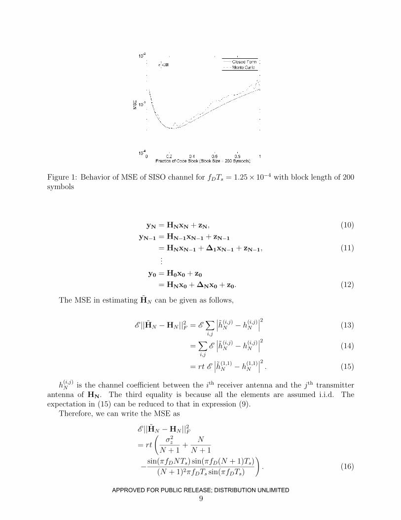
Figure 1: Behavior of MSE of SISO channel for fDTs = 1.25× 10⁻⁴ with block length of 200symbols
yN = HNxN + zN, (10)
yN−1 = HN−1xN−1 + zN−1
= HNxN−1 + ∆1xN−1 + zN−1, (11)...
y0 = H0x0 + z0
= HNx0 + ∆Nx0 + z0. (12)
The MSE in estimating HN can be given as follows,
E ||HN −HN ||2F = E∑i,j
∣∣∣h(i,j)N − h(i,j)N
∣∣∣2 (13)
=∑i,j
E∣∣∣h(i,j)N − h(i,j)N
∣∣∣2 (14)
= rt E∣∣∣h(1,1)N − h(1,1)N
∣∣∣2 . (15)
h(i,j)N is the channel coefficient between the ith receiver antenna and the jth transmitter
antenna of HN. The third equality is because all the elements are assumed i.i.d. Theexpectation in (15) can be reduced to that in expression (9).
Therefore, we can write the MSE as
E ||HN −HN ||2F= rt
(σ2z
N + 1+
N
N + 1
−sin(πfDNTs) sin(πfD(N + 1)Ts)
(N + 1)2πfDTs sin(πfDTs)
). (16)
9APPROVED FOR PUBLIC RELEASE; DISTRIBUTION UNLIMITED
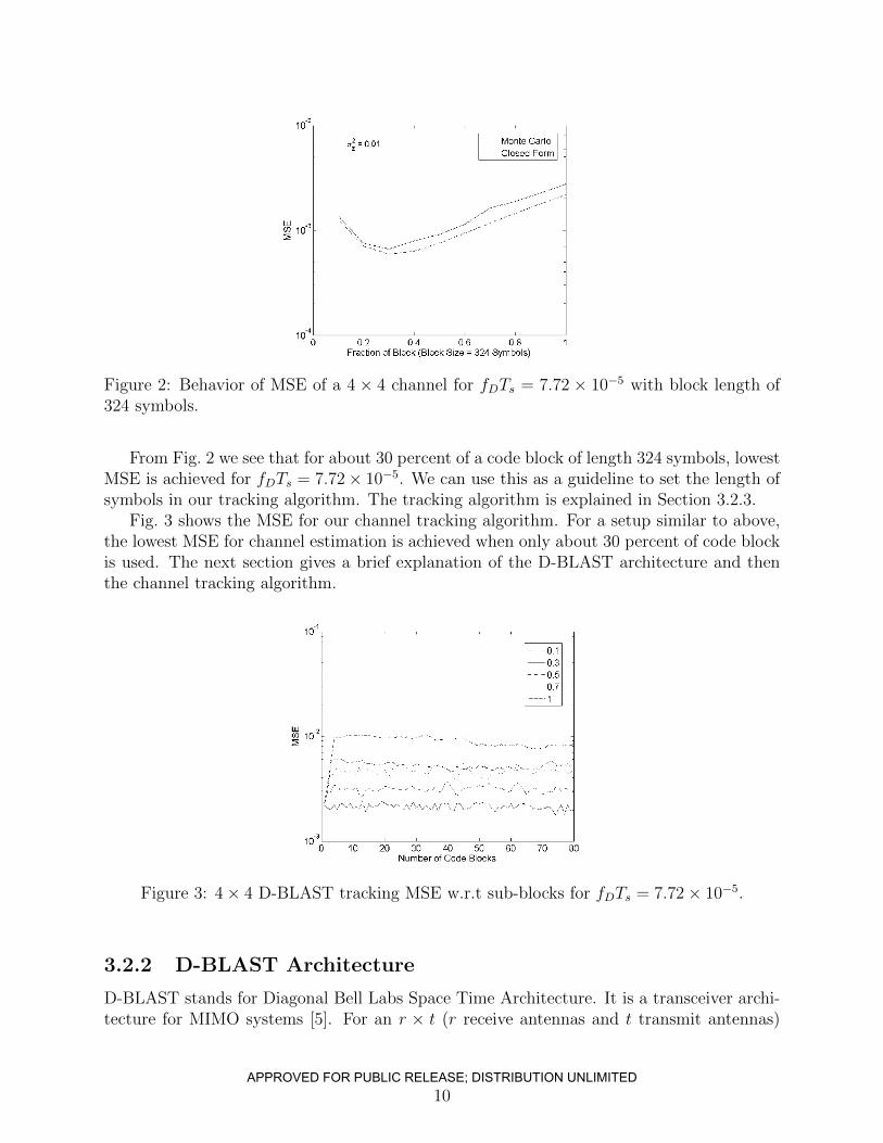
Figure 2: Behavior of MSE of a 4 × 4 channel for fDTs = 7.72 × 10⁻⁵ with block length of324 symbols.
From Fig. 2 we see that for about 30 percent of a code block of length 324 symbols, lowestMSE is achieved for fDTs = 7.72× 10⁻⁵. We can use this as a guideline to set the length ofsymbols in our tracking algorithm. The tracking algorithm is explained in Section 3.2.3.
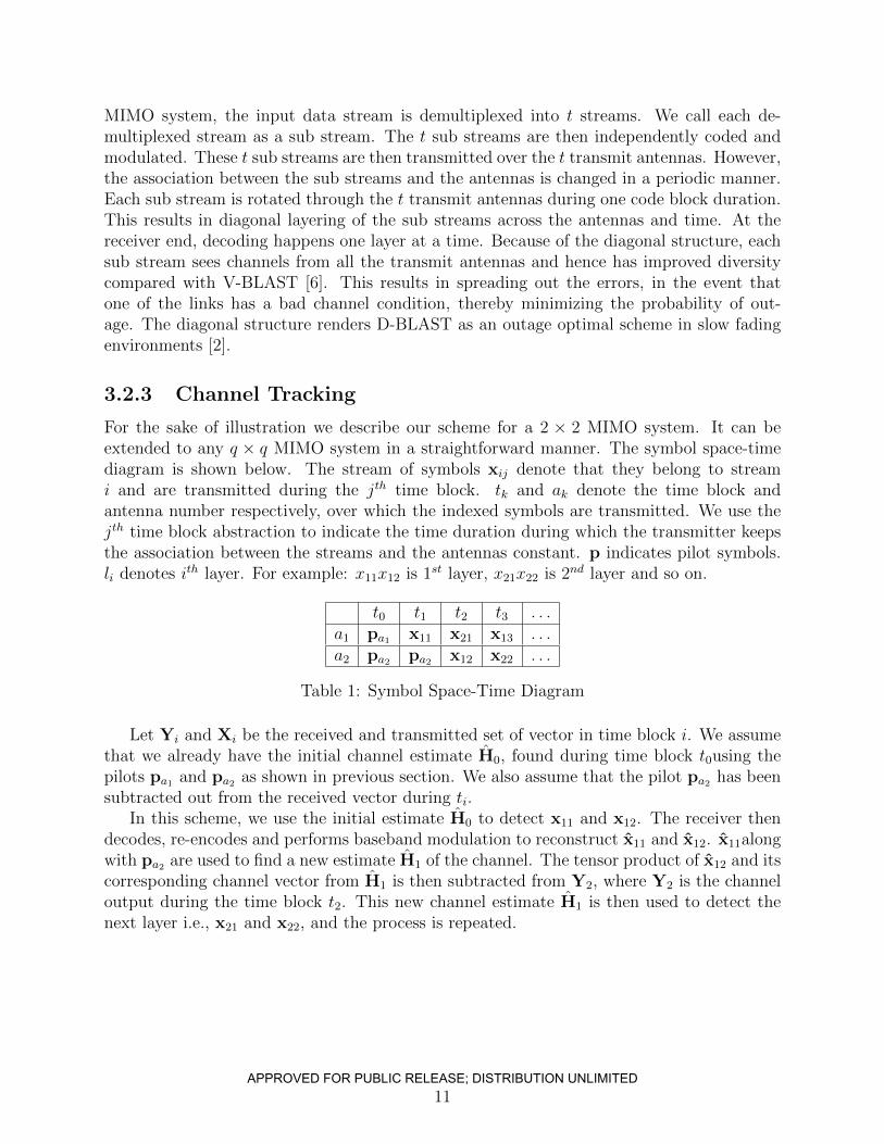
Fig. 3 shows the MSE for our channel tracking algorithm. For a setup similar to above,the lowest MSE for channel estimation is achieved when only about 30 percent of code blockis used. The next section gives a brief explanation of the D-BLAST architecture and thenthe channel tracking algorithm.
Figure 3: 4× 4 D-BLAST tracking MSE w.r.t sub-blocks for fDTs = 7.72× 10⁻⁵.
3.2.2 D-BLAST Architecture
D-BLAST stands for Diagonal Bell Labs Space Time Architecture. It is a transceiver archi-tecture for MIMO systems [5]. For an r × t (r receive antennas and t transmit antennas)
10APPROVED FOR PUBLIC RELEASE; DISTRIBUTION UNLIMITED
MIMO system, the input data stream is demultiplexed into t streams. We call each de-multiplexed stream as a sub stream. The t sub streams are then independently coded andmodulated. These t sub streams are then transmitted over the t transmit antennas. However,the association between the sub streams and the antennas is changed in a periodic manner.Each sub stream is rotated through the t transmit antennas during one code block duration.This results in diagonal layering of the sub streams across the antennas and time. At thereceiver end, decoding happens one layer at a time. Because of the diagonal structure, eachsub stream sees channels from all the transmit antennas and hence has improved diversitycompared with V-BLAST [6]. This results in spreading out the errors, in the event thatone of the links has a bad channel condition, thereby minimizing the probability of out-age. The diagonal structure renders D-BLAST as an outage optimal scheme in slow fadingenvironments [2].
3.2.3 Channel Tracking
For the sake of illustration we describe our scheme for a 2 × 2 MIMO system. It can beextended to any q × q MIMO system in a straightforward manner. The symbol space-timediagram is shown below. The stream of symbols xij denote that they belong to streami and are transmitted during the jth time block. tk and ak denote the time block andantenna number respectively, over which the indexed symbols are transmitted. We use thejth time block abstraction to indicate the time duration during which the transmitter keepsthe association between the streams and the antennas constant. p indicates pilot symbols.li denotes ith layer. For example: x11x12 is 1st layer, x21x22 is 2nd layer and so on.
t0 t1 t2 t3 . . .a1 pa1 x11 x21 x13 . . .a2 pa2 pa2 x12 x22 . . .
Table 1: Symbol Space-Time Diagram
Let Yi and Xi be the received and transmitted set of vector in time block i. We assumethat we already have the initial channel estimate H0, found during time block t0using thepilots pa1 and pa2 as shown in previous section. We also assume that the pilot pa2 has beensubtracted out from the received vector during ti.
In this scheme, we use the initial estimate H0 to detect x11 and x12. The receiver thendecodes, re-encodes and performs baseband modulation to reconstruct x11 and x12. x11alongwith pa2 are used to find a new estimate H1 of the channel. The tensor product of x12 and itscorresponding channel vector from H1 is then subtracted from Y2, where Y2 is the channeloutput during the time block t2. This new channel estimate H1 is then used to detect thenext layer i.e., x21 and x22, and the process is repeated.
11APPROVED FOR PUBLIC RELEASE; DISTRIBUTION UNLIMITED
3.3 Results and Discussion
3.3.1 Channel Tracking
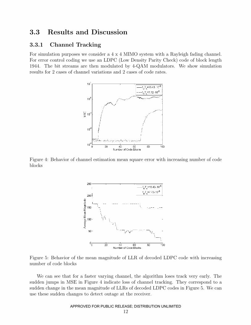
For simulation purposes we consider a 4 x 4 MIMO system with a Rayleigh fading channel.For error control coding we use an LDPC (Low Density Parity Check) code of block length1944. The bit streams are then modulated by 4-QAM modulators. We show simulationresults for 2 cases of channel variations and 2 cases of code rates.
Figure 4: Behavior of channel estimation mean square error with increasing number of codeblocks
Figure 5: Behavior of the mean magnitude of LLR of decoded LDPC code with increasingnumber of code blocks
We can see that for a faster varying channel, the algorithm loses track very early. Thesudden jumps in MSE in Figure 4 indicate loss of channel tracking. They correspond to asudden change in the mean magnitude of LLRs of decoded LDPC codes in Figure 5. We canuse these sudden changes to detect outage at the receiver.
12APPROVED FOR PUBLIC RELEASE; DISTRIBUTION UNLIMITED
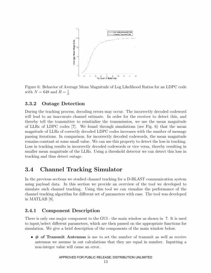
Figure 6: Behavior of Average Mean Magnitude of Log Likelihood Ratios for an LDPC codewith N = 648 and R = 1
2
3.3.2 Outage Detection
During the tracking process, decoding errors may occur. The incorrectly decoded codewordwill lead to an inaccurate channel estimate. In order for the receiver to detect this, andthereby tell the transmitter to reinitialize the transmission, we use the mean magnitudeof LLRs of LDPC codes [7]. We found through simulations (see Fig. 6) that the meanmagnitude of LLRs of correctly decoded LDPC codes increases with the number of messagepassing iterations. In comparison, for incorrectly decoded codewords, the mean magnituderemains constant at some small value. We can use this property to detect the loss in tracking.Loss in tracking results in incorrectly decoded codewords or vice versa, thereby resulting insmaller mean magnitude of the LLRs. Using a threshold detector we can detect this loss intracking and thus detect outage.
3.4 Channel Tracking Simulator
In the previous sections we studied channel tracking for a D-BLAST communication systemusing payload data. In this section we provide an overview of the tool we developed tosimulate such channel tracking. Using this tool we can visualize the performance of thechannel tracking algorithm for different set of parameters with ease. The tool was developedin MATLAB [8].
3.4.1 Component Description
There is only one major component to the GUI - the main window as shown in 7. It is usedto input/select different parameters, which are then passed on the appropriate functions forsimulation. We give a brief description of the components of the main window below.
• # of Transmit Antennas is use to set the number of transmit as well as receiveantennas we assume in out calculations that they are equal in number. Inputting anon-integer value will cause an error.
13APPROVED FOR PUBLIC RELEASE; DISTRIBUTION UNLIMITED
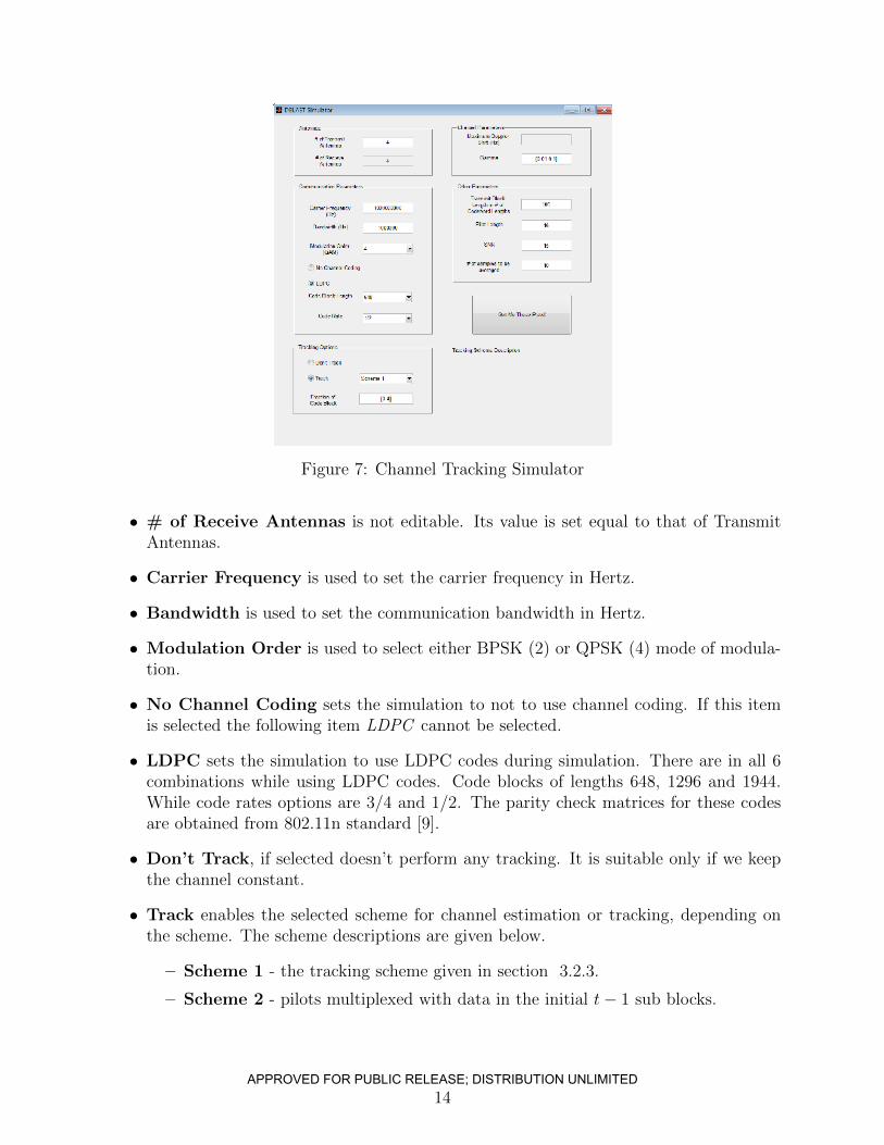
Figure 7: Channel Tracking Simulator
• # of Receive Antennas is not editable. Its value is set equal to that of TransmitAntennas.
• Carrier Frequency is used to set the carrier frequency in Hertz.
• Bandwidth is used to set the communication bandwidth in Hertz.
• Modulation Order is used to select either BPSK (2) or QPSK (4) mode of modula-tion.
• No Channel Coding sets the simulation to not to use channel coding. If this itemis selected the following item LDPC cannot be selected.
• LDPC sets the simulation to use LDPC codes during simulation. There are in all 6combinations while using LDPC codes. Code blocks of lengths 648, 1296 and 1944.While code rates options are 3/4 and 1/2. The parity check matrices for these codesare obtained from 802.11n standard [9].
• Don’t Track, if selected doesn’t perform any tracking. It is suitable only if we keepthe channel constant.
• Track enables the selected scheme for channel estimation or tracking, depending onthe scheme. The scheme descriptions are given below.
– Scheme 1 - the tracking scheme given in section 3.2.3.
– Scheme 2 - pilots multiplexed with data in the initial t− 1 sub blocks.
14APPROVED FOR PUBLIC RELEASE; DISTRIBUTION UNLIMITED
– Scheme 3 - same as scheme 1, except that in this case we can set how muchfraction of code-block to be used for channel tracking, whereas in scheme it wasfixed to one sub block.
– Scheme 4 - a scheme, wherein we distribute the pilots across the payload.
– Fraction of Code Block - this value has different interpretations. For Scheme1 & 2 it is of no use. For Scheme 3, it means the fraction of code block to be usedfor channel estimation. In this case we can set it as an array of different values.For Scheme 4, it indicates the fraction of code block between two pilot symbolblocks. The value should not be an array in this case.
• Maximum Doppler Shift. This edit box is not functional.
• Gamma is used to set the maximum Doppler shift. Gamma is define as, γ =time to send one code block
channel coherence time. We use the gamma values to calculate maximum Doppler shift,
which are then used to generate the channel coefficients.
• Transmit Block Length in # of Codeword Lengths is self-explanatory.
• Pilot Length is used to set the length of pilot block in number of symbol periods.
• SNR is used to set the average signal to noise ratio at each receiver antenna in decibels.
• # of samples to be averaged are the number of Monte Carlo runs that we averageto get the sample statistics.
3.5 Conclusion
In this chapter we studied channel tracking for a D-BLAST communication system usingpayload data. Since the tracking involves using previously detected data symbols, a closed-form expression for channel MSE as a function of the number of training symbols, maximumDoppler spread and symbol duration was derived for a SISO link in a diffuse scatteringenvironment. This expression was then extended to MIMO links. We use this analysis tofind the optimum length of previously detected symbols for channel tracking. In the eventthe receiver loses track of the channel, we show, using simulations, that using the meanmagnitude of log likelihood ratios of LDPC codes can detect the event of a decoding error,which in turn can be used to detect outage.
We have also provided a MATLAB based channel tracking simulator. It can be used toeasily simulate the developed channel tracking and outage detection schemes.
15APPROVED FOR PUBLIC RELEASE; DISTRIBUTION UNLIMITED
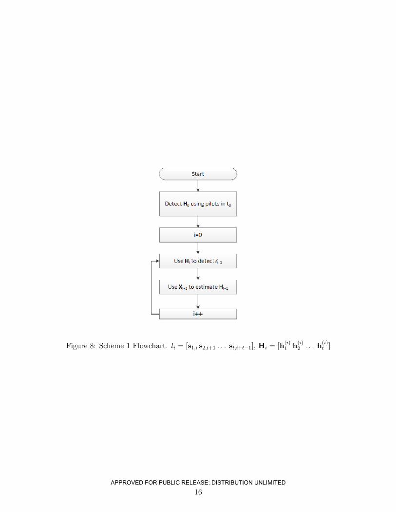
Figure 8: Scheme 1 Flowchart. li = [s1,i s2,i+1 . . . st,i+t−1], Hi = [h(i)1 h
(i)2 . . . h
(i)t ]
16
APPROVED FOR PUBLIC RELEASE; DISTRIBUTION UNLIMITED
Variable Rate MIMO
4.1 Introduction
The use of autonomous/unmanned vehicles for various civilian and military applicationshas become increasingly prevalent. The absence of human pilots on board those unmannedsystems, however, make it a challenging task to accomplish various intended missions. Forexample, these unmanned systems are often remotely piloted and thus having a reliable androbust communication link between the aerial systems and the ground control unit is impera-tive. Even for systems that are semi-autonomous, having a high throughput communicationlink is often essential to accomplishing any intended mission. Many remotely piloted air-crafts (RPAs) are used for surveillance applications and the need to stream surveillance data,including real time video data requires a highly reliable and high-throughput communicationlink from the RPAs to ground units.
Many legacy communication links (e.g., Link 16 with a data rate not more than 16kb/s)operate at a data rate that becomes highly inadequate for applications where video streamingfrom aerial systems to ground is needed. Merely scaling up the power/bandwidth is bothlimited by resource and policy constraints as well as the fundamental theoretical limitsdictated by the Shannon theory. A promising technology is the use of multiple antennacommunication systems [5, 10, 11]. The so-called multiple-input multiple-output (MIMO)communication scales up data rate linearly as the number of antennas increase and thusprovides great potential for improving the throughput of air to ground communication. Thishelps enable many envisioned applications that may otherwise be infeasible.
MIMO communications, however, are traditionally designed for the so-called scatteringenvironment [2] where independent channel variations between different transmit/receiveantenna pairs are exploited. For airborne platforms, however, there has been a debate aboutthe feasibility of MIMO communications because of the lack of scattering. However, forcertain communication ranges, the large aperture that an aircraft affords makes MIMO anappealing choice of communication that can attain significantly higher throughput given afixed power/bandwidth budget compared with single antenna systems even in the absenceof any scatterers [12].
This chapter describes an ongoing research and development effort that uses MIMOcommunications to enable robust and high capacity connectivity between RPAs and ground
17APPROVED FOR PUBLIC RELEASE; DISTRIBUTION UNLIMITED
terminals. While the large aperture may compensate for the lack of the scattering, twounique challenges still exist for airborne MIMO communications. The large aperture is onlyattained when antennas are placed strategically apart on a RPA. In the absence of scattering,i.e., when communications are limited by line-of-sight channels, the fact that some antennaelements on a RPA may be completely out of sight from its communicating party mayrender the channel matrix ill-conditioned. This is further complicated by the high mobilityand maneuverability of the RPA which make it infeasible to have complete channel stateinformation (CSI) at the transmitter. To address these challenges, we propose a variable rateMIMO communication scheme that combines the D-BLAST architecture with per antennaspreading to harvest the maximum possible throughput gain allowed by the channel.
The chapter is organized as follows. Section 4.2.1 describes the channel measurementapparatus. The measurement data provides guidance on the potential throughput gain forthe particular application of interest as well as challenges in realizing the throughput gainto address these challenges. Section 4.2.2 introduces a modified D-BLAST architecture toaddress these challenges. Section 4.3 describes simulation results using the real measurementchannels to show the potential improvement using the proposed variable MIMO scheme.
We use the following notations throughout the chapter: ∗ denotes complex conjugate,CN stands for complex Gaussian, T is transpose, + is conjugate transpose, 0 is a zero vectorand Ik is a k × k identity matrix. Small letters denote scalars, bold small letters denotecolumn vectors and bold capital letters denote matrices.
4.2 Methods, Assumptions and Procedures
4.2.1 MIMO Channel State Matrix Measurements
Measurement Apparatus
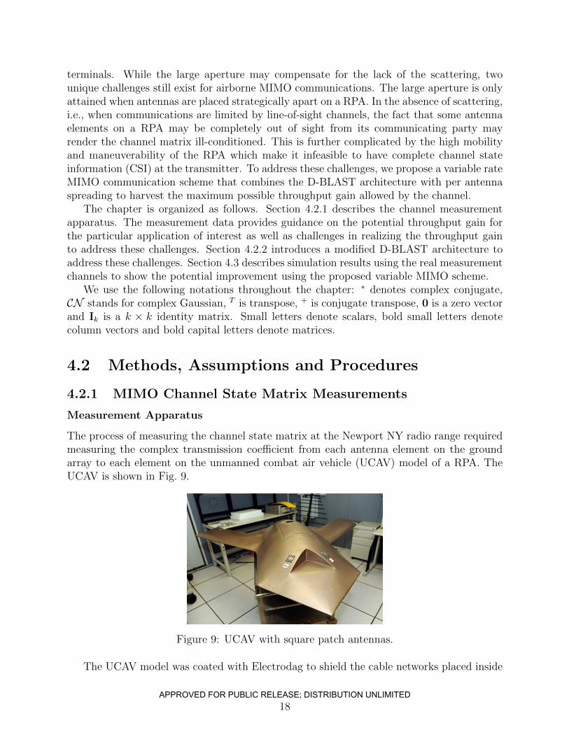
The process of measuring the channel state matrix at the Newport NY radio range requiredmeasuring the complex transmission coefficient from each antenna element on the groundarray to each element on the unmanned combat air vehicle (UCAV) model of a RPA. TheUCAV is shown in Fig. 9.
Figure 9: UCAV with square patch antennas.
The UCAV model was coated with Electrodag to shield the cable networks placed inside
18APPROVED FOR PUBLIC RELEASE; DISTRIBUTION UNLIMITED
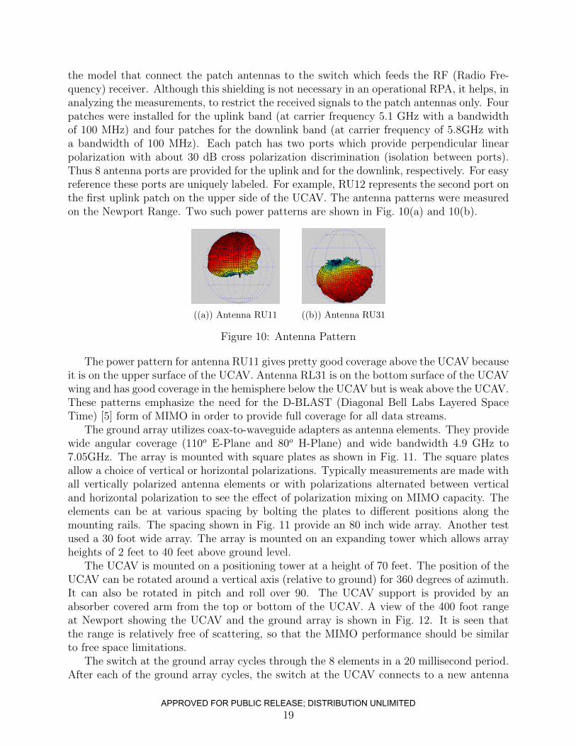
the model that connect the patch antennas to the switch which feeds the RF (Radio Fre-quency) receiver. Although this shielding is not necessary in an operational RPA, it helps, inanalyzing the measurements, to restrict the received signals to the patch antennas only. Fourpatches were installed for the uplink band (at carrier frequency 5.1 GHz with a bandwidthof 100 MHz) and four patches for the downlink band (at carrier frequency of 5.8GHz witha bandwidth of 100 MHz). Each patch has two ports which provide perpendicular linearpolarization with about 30 dB cross polarization discrimination (isolation between ports).Thus 8 antenna ports are provided for the uplink and for the downlink, respectively. For easyreference these ports are uniquely labeled. For example, RU12 represents the second port onthe first uplink patch on the upper side of the UCAV. The antenna patterns were measuredon the Newport Range. Two such power patterns are shown in Fig. 10(a) and 10(b).
((a)) Antenna RU11 ((b)) Antenna RU31
Figure 10: Antenna Pattern
The power pattern for antenna RU11 gives pretty good coverage above the UCAV becauseit is on the upper surface of the UCAV. Antenna RL31 is on the bottom surface of the UCAVwing and has good coverage in the hemisphere below the UCAV but is weak above the UCAV.These patterns emphasize the need for the D-BLAST (Diagonal Bell Labs Layered SpaceTime) [5] form of MIMO in order to provide full coverage for all data streams.
The ground array utilizes coax-to-waveguide adapters as antenna elements. They providewide angular coverage (110o E-Plane and 80o H-Plane) and wide bandwidth 4.9 GHz to7.05GHz. The array is mounted with square plates as shown in Fig. 11. The square platesallow a choice of vertical or horizontal polarizations. Typically measurements are made withall vertically polarized antenna elements or with polarizations alternated between verticaland horizontal polarization to see the effect of polarization mixing on MIMO capacity. Theelements can be at various spacing by bolting the plates to different positions along themounting rails. The spacing shown in Fig. 11 provide an 80 inch wide array. Another testused a 30 foot wide array. The array is mounted on an expanding tower which allows arrayheights of 2 feet to 40 feet above ground level.
The UCAV is mounted on a positioning tower at a height of 70 feet. The position of theUCAV can be rotated around a vertical axis (relative to ground) for 360 degrees of azimuth.It can also be rotated in pitch and roll over 90. The UCAV support is provided by anabsorber covered arm from the top or bottom of the UCAV. A view of the 400 foot rangeat Newport showing the UCAV and the ground array is shown in Fig. 12. It is seen thatthe range is relatively free of scattering, so that the MIMO performance should be similarto free space limitations.
The switch at the ground array cycles through the 8 elements in a 20 millisecond period.After each of the ground array cycles, the switch at the UCAV connects to a new antenna
19APPROVED FOR PUBLIC RELEASE; DISTRIBUTION UNLIMITED

((a)) Plate ((b)) Plate Schematic
((c)) Ground Array
Figure 11: Element Ground Array
Figure 12: UCAV and Ground Array on the 400 ft. Newport Range.
port of the 16 UCAV antenna ports. As this switching is completed the azimuth turntablemoves to a new position for a given pattern cut. At each position of the cut, the complextransmission coefficient from each antenna element on the ground array to each element porton the UCAV is recorded. The frequency and pitch and yaw positions can be modified fornew cuts.
Challenges
Fig. 10(a) and 10(b) illustrate the unique challenges of airborne MIMO. Each antenna el-ement has only limited visibility for communication, depending on the orientations of thetransceiver pair. This is further exacerbated by the lack of channel state information at thetransmitter - RPAs are not only of high mobility but they may maneuver in-flight whichmakes it infeasible to constantly feedback channel state to the transmitter.
Nevertheless, the channel matrices indicate that there exists significant theoretical through-
20APPROVED FOR PUBLIC RELEASE; DISTRIBUTION UNLIMITED
put improvement through MIMO communications if designed properly. In the following, wedescribe a simple variable rate MIMO scheme to address the above mentioned challenges.We demonstrate through numerical simulation that the proposed scheme is capable of over-coming the above challenges and realizing significant performance gain.
Measurement Data
We obtain measurement data for the following two configurations.
LRPRM This configuration consists of setting the 80 inch wide ground array at 2 feetabove the ground level. The polarization of the antenna elements is alternated be-tween vertical and horizontal polarization. The UCAV has the same configuration asmentioned in the previous section.
LRPRV Same as LRPRM except all the antenna elements transmit with vertical polariza-tion. This configuration consists of setting the 80 inch wide ground array at 2 feet above the ground level, but all the antenna elements transmit with vertical polarization.
4.2.2 Variable Rate MIMO
While the channel matrix measurements exhibit potential for significant throughput im-provement via MIMO communications, significant challenges exist that need to be overcomein order to realize this potential. In particular, the lack of scattering makes the channel sus-ceptible to ill-conditioning when antenna elements may be out of sight to the communicatingparty. In the absence of complete CSI at the transmitter, there is a need to ensure that anyindependent data stream is not stuck with an antenna element that is out-of-sight. Thismakes D-BLAST a very natural candidate for such applications. D-BLAST is an outageoptimal transceiver architecture for MIMO communication system [2, 5]. The architectureessentially involves independent coding and modulation of N data streams and rotating eachstream through all the transmit antennas. Here, N is the number of transmit antennas. Therotation is performed in a way that makes sure that each stream experiences the channelfrom all the transmit antennas and all levels of interference i.e., no interference to experi-encing interference from all of the other N −1 streams at the receiver as each stream rotatesin the space-time domain.
The verbatim application of D-BLAST, however, is still inadequate when channel ma-trices are highly ill-conditioned. The existence of antennas that experience channel outagedue to blockage will drag down the overall performance. From a theoretical viewpoint, theindependent data streams accommodated in a MIMO channel should be no larger than theeffective rank of the matrix. The challenge is, in the absence of complete CSI at the trans-mitter, how to utilize the advantage of D-BLAST while being able to handle the potentialrank deficiency of channel matrices.
We propose a simple scheme of variable rate MIMO - the variable rate is not only achievedthough the traditional means of controlling the coding rate as well as modulation order, butthe number of independent data streams is also adapted through per antenna spreading.The modified D-BLAST architecture is illustrated in Fig. 5. Without loss of generality, weassume the MIMO system has N transmit and N receive antennas. At the transmitter side,
21APPROVED FOR PUBLIC RELEASE; DISTRIBUTION UNLIMITED
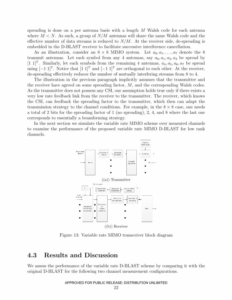
spreading is done on a per antenna basis with a length M Walsh code for each antennawhere M < N . As such, a group of N/M antennas will share the same Walsh code and theeffective number of data streams is reduced to N/M . At the receiver side, de-spreading isembedded in the D-BLAST receiver to facilitate successive interference cancellation.
As an illustration, consider an 8 × 8 MIMO system. Let a0, a1, . . . , a7 denote the 8transmit antennas. Let each symbol from any 4 antennas, say a0, a1, a2, a3 be spread by[1 1]T . Similarly, let each symbols from the remaining 4 antennas, a4, a5, a6, a7 be spreadusing [−1 1]T . Notice that [1 1]T and [−1 1]T are orthogonal to each other. At the receiver,de-spreading effectively reduces the number of mutually interfering streams from 8 to 4.
The illustration in the previous paragraph implicitly assumes that the transmitter andthe receiver have agreed on some spreading factor, M , and the corresponding Walsh codes.As the transmitter does not possess any CSI, our assumption holds true only if there exists avery low rate feedback link from the receiver to the transmitter. The receiver, which knowsthe CSI, can feedback the spreading factor to the transmitter, which then can adapt thetransmission strategy to the channel conditions. For example, in the 8 × 8 case, one needsa total of 2 bits for the spreading factor of 1 (no spreading), 2, 4, and 8 where the last onecorresponds to essentially a beamforming strategy.
In the next section we simulate the variable rate MIMO scheme over measured channelsto examine the performance of the proposed variable rate MIMO D-BLAST for low rankchannels.
((a)) Transmitter
((b)) Receiver
Figure 13: Variable rate MIMO transceiver block diagram
4.3 Results and Discussion
We assess the performance of the variable rate D-BLAST scheme by comparing it with theoriginal D-BLAST for the following two channel measurement configurations.
22APPROVED FOR PUBLIC RELEASE; DISTRIBUTION UNLIMITED
• All Vertical Polarization (VP).
• Mixed Polarization (MP).
As mentioned earlier, we are motivated to use VP and MP to see the effect of polarizationmixing on MIMO capacity. The channels obtained using VP tend be rank deficient. On theother hand, channels obtained using MP tend to have a higher rank than that of VP. This isbecause the two polarizations effectively serve to create two orthogonal channels. This leadsto more well-conditioned MP channel matrices than the corresponding VP ones.
For each of the above two configurations we have obtained about 13,000 channel measure-ments, each of which corresponds to a unique combination of azimuth and elevation. Duringsimulation, we select 10% of the channels at random, and measure the average outage overthese channels.
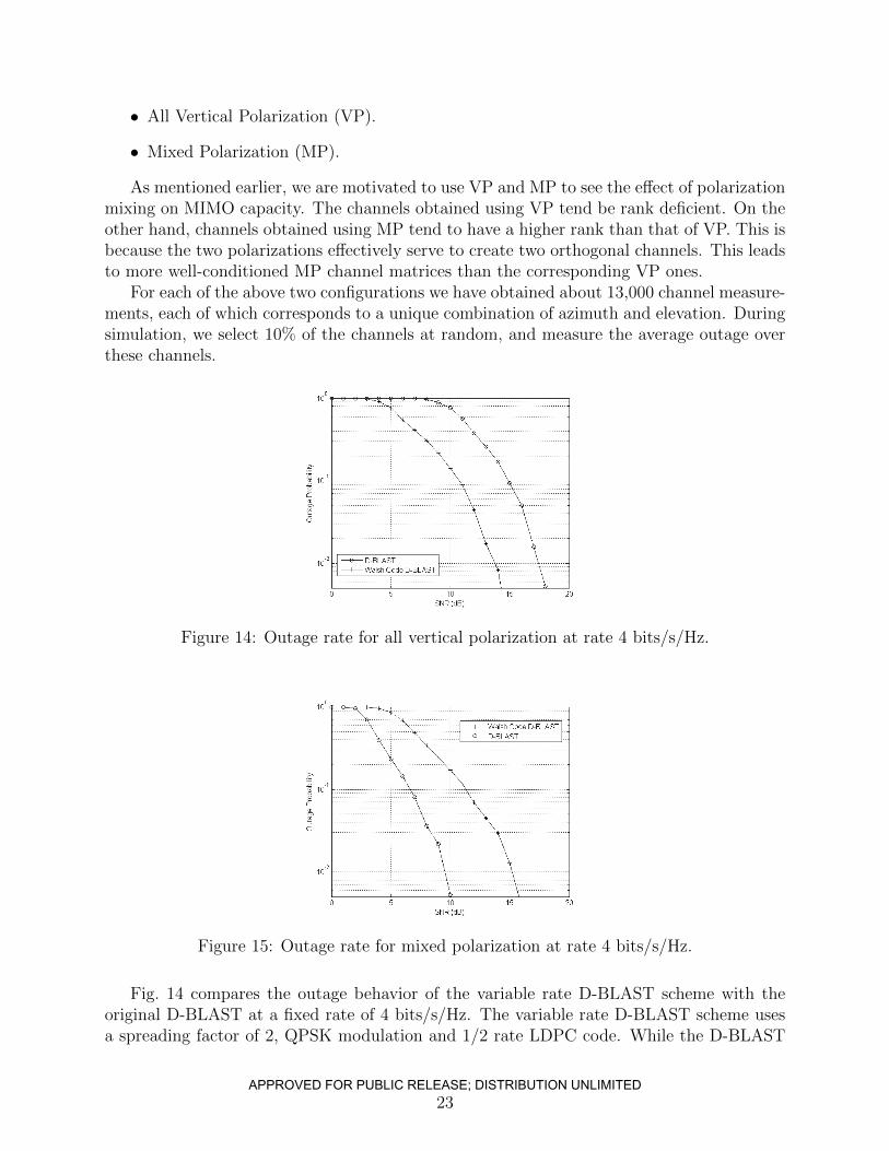
Figure 14: Outage rate for all vertical polarization at rate 4 bits/s/Hz.
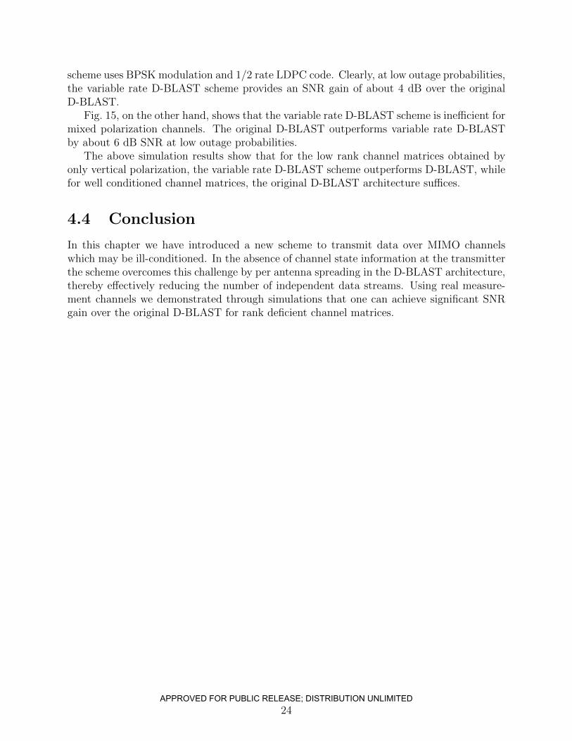
Figure 15: Outage rate for mixed polarization at rate 4 bits/s/Hz.
Fig. 14 compares the outage behavior of the variable rate D-BLAST scheme with theoriginal D-BLAST at a fixed rate of 4 bits/s/Hz. The variable rate D-BLAST scheme usesa spreading factor of 2, QPSK modulation and 1/2 rate LDPC code. While the D-BLAST
23APPROVED FOR PUBLIC RELEASE; DISTRIBUTION UNLIMITED
scheme uses BPSK modulation and 1/2 rate LDPC code. Clearly, at low outage probabilities,the variable rate D-BLAST scheme provides an SNR gain of about 4 dB over the originalD-BLAST.
Fig. 15, on the other hand, shows that the variable rate D-BLAST scheme is inefficient formixed polarization channels. The original D-BLAST outperforms variable rate D-BLASTby about 6 dB SNR at low outage probabilities.
The above simulation results show that for the low rank channel matrices obtained byonly vertical polarization, the variable rate D-BLAST scheme outperforms D-BLAST, whilefor well conditioned channel matrices, the original D-BLAST architecture suffices.
4.4 Conclusion
In this chapter we have introduced a new scheme to transmit data over MIMO channelswhich may be ill-conditioned. In the absence of channel state information at the transmitterthe scheme overcomes this challenge by per antenna spreading in the D-BLAST architecture,thereby effectively reducing the number of independent data streams. Using real measure-ment channels we demonstrated through simulations that one can achieve significant SNRgain over the original D-BLAST for rank deficient channel matrices.
24APPROVED FOR PUBLIC RELEASE; DISTRIBUTION UNLIMITED
GnuRadio MIMO ImplementationUsing USRP N210
5.1 Introduction
To facilitate experimental validation of variable rate MIMO we have developed a softwaredefined 2×2 MIMO system using GNU Radio/USRP platform [1,13]. In this setup the GNURadio based software performs all the baseband signal processing, whereas USRPs act asthe wireless interfaces. To form a 2 antenna terminal, two USRP N210 are chained togetherusing a vendor supplied cable. Thereby, a total of 4 USRPs combined with the GNU Radiobased baseband signal processing constitute our 2× 2 MIMO implementation. Nevertheless,the software implementation is scalable to higher antenna dimensions under the constraintthat the number of transmit antennas is equal to that of receive antennas and some changesto the symbol timing estimator in the receive chain.
An important feature of this implementation is the decoupling of GNU Radio with theDBLAST encoding/decoding functionality: The DBLAST decoder/encoder c++ library isdeveloped separately which is then used as a shared library by the GNU Radio modules.Such separation increases the potential of code re-usability. We will revisit this aspect of ourimplementation in Section 5.2.2. In the next section we provide high level block diagramsthat represent the implementation approach.
5.2 Methods, Assumptions and Procedures
5.2.1 System Overview
Fig. 16 shows the transmitter block diagram. As shown, an input byte stream is first de-multiplexed and then given to the DBLAST Encoder. The DBLAST encoder performschannel encoding, digital constellation mapping and the diagonal layering of the two incom-ing streams. The two output streams of the encoder are then fed to two upsampling RRCFilters (root raised cosine). The outputs of these filters are then fed to two separate USRPN210s, which share a common 10 MHz reference clock.
Fig. 17 shows the structure of the receiver. The outputs from the two synchronized
25APPROVED FOR PUBLIC RELEASE; DISTRIBUTION UNLIMITED
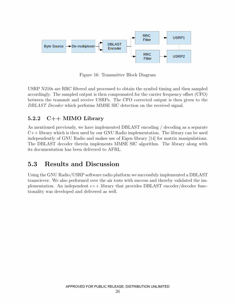
Figure 16: Transmitter Block Diagram
USRP N210s are RRC filtered and processed to obtain the symbol timing and then sampledaccordingly. The sampled output is then compensated for the carrier frequency offset (CFO)between the transmit and receive USRPs. The CFO corrected output is then given to theDBLAST Decoder which performs MMSE SIC detection on the received signal.
5.2.2 C++ MIMO Library
As mentioned previously, we have implemented DBLAST encoding / decoding as a separateC++ library which is then used by our GNU Radio implementation. The library can be usedindependently of GNU Radio and makes use of Eigen library [14] for matrix manipulations.The DBLAST decoder therein implements MMSE SIC algorithm. The library along withits documentation has been delivered to AFRL.
5.3 Results and Discussion
Using the GNU Radio/USRP software radio platform we successfuly implemented a DBLASTtransciever. We also performed over the air tests with success and thereby validated the im-plementation. An independent c++ library that provides DBLAST encoder/decoder func-tionality was developed and delivered as well.
26APPROVED FOR PUBLIC RELEASE; DISTRIBUTION UNLIMITED
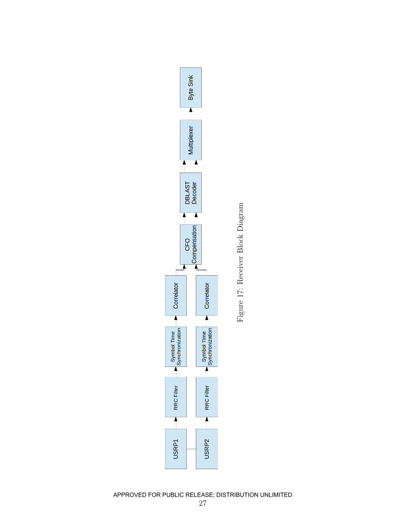
Fig
ure
17:
Rec
eive
rB
lock
Dia
gram
27APPROVED FOR PUBLIC RELEASE; DISTRIBUTION UNLIMITED
Conclusion
In this report we studied problems relating to airborne MIMO communication and deliveredrelevant MATLAB, GNU Radio and C++ based simulation and experimentation software.
Firstly, we studied the problem of channel tracking in dynamic conditions entailed inairborne MIMO communication. In doing so, we developed a scheme to estimate and keepthe channel state information current using payload data. We analyzed the scheme andprovided a closed form expression to determine optimal symbol length needed to estimatethe channel in a continuously fading Rayleigh environment. In addition, we have provideda channel tracking simulator, developed in MATLAB, to quickly test different scenarios.
Secondly, by studying the real measurement data, we found out that the wireless channel matrices offered therein are severely rank deficient. Traditional MIMO architectures, whichare developed to take advantage of well conditioned MIMO channel matrices, fail to takeadvantage of such rank deficient channels. We developed a Variable Rate MIMO scheme toovercome the problem of communication over rank deficient channels. Through simulationswe showed that the developed scheme significantly outperforms D-BLAST for rank deficientchannel matrices.
Finally, we provided a GNU Radio based 2 × 2 D-BLAST implementation, to facilitateexperimentation. Further, we developed a C++ library that implements D-BLAST encoderand decoder.
28APPROVED FOR PUBLIC RELEASE; DISTRIBUTION UNLIMITED
References
[1] USRP: Universal Software Radio Peripheral, accessed September 2013. [Online].Available: http://www.ettus.com
[2] D. Tse and P. Viswanath, Fundamentals of Wireless Communications. Cambridge,UK: Cambridge University Press, 2005.
[3] Q. Sun, D. Cox, H. Huang, and A. Lozano, “Estimation of continuous flat fading MIMOchannels,” IEEE Trans. Wireless Commun., vol. 1, no. 4, pp. 549–553, 2002.
[4] V. Pohl, P. Nguyen, V. Jungnickel, and C. von Helmolt, “Continuous flat-fading MIMOchannels: Achievable rate and optimal length of the training and data phases,” IEEETrans. Wireless Commun., vol. 4, no. 4, pp. 1889–1900, 2005.
[5] G. J. Foschini, “Layered Space-Time Architecture for Wireless Communication in aFading Environment When Using Multi-Element Antennas,” Bell Laboratories TechnicalJournal, vol. 1, no. 2, pp. 41–59, 1996.
[6] G. Foschini, D. Chizhik, M. Gans, C. Papadias, and R. Valenzuela, “Analysis andperformance of some basic space-time architectures,” IEEE Journal on Selected Areasin Communications, vol. 21, no. 3, pp. 303–320, 2003.
[7] J. Li, X. You, and J. Li, “Early stopping for LDPC decoding: convergence of meanmagnitude (cmm),” IEEE Commun. Lett., vol. 10, no. 9, pp. 667–669, 2006.
[8] MATLAB, 7.13.0.564 (R2011b). Natick, Massachusetts: The MathWorks Inc., 2011.
[9] IEEE 802.11n-2009 (Section 20.3). http://standards.ieee.org/ndstds/standard/802.11n-2009.html.
[10] G. J. Foschini and M. J. Gans, “On Limits Of Wireless Communications in a FadingEnvironment When Using Multiple Antennas,” Wireless Personal Commun., vol. 6,no. 3, pp. 311–335, 1998.
[11] E. Telatar, “Capacity of Multi-antenna Gaussian Channels,” Europ. Trans. Telecom-mun., vol. 10, no. 6, pp. 585–595, 1999.
[12] M. J. Gans, “Aircraft Free-Space MIMO Communications,” in Proc 43rd AsilomarConference on Signals, Systems and Computers, Pacific Grove, CA, Nov. 2009.
[13] GNU Radio, accessed September 2013. [Online]. Available: http://www.gnuradio.org
29APPROVED FOR PUBLIC RELEASE; DISTRIBUTION UNLIMITED

[14] G. Guennebaud, B. Jacob et al., “Eigen v3,” http://eigen.tuxfamily.org, 2010.
30APPROVED FOR PUBLIC RELEASE; DISTRIBUTION UNLIMITED

Symbols, Abbreviations andAcronyms
0 zero vector with appropriate dimension depending on the context
Ik identity matrix of dimension with k columns and k rows.
X matrix denoted by uppercase bold letter
x column vector denoted by lowercase bold letter
∗ complex conjugate operator
+ Hermitian matrix operator
T transpose operator
r × t wireless communication system with r receive antennas and t transmit antennas
x scalar denoted by lower case letter
BPSK binary phase shift keying
CSI channel state information
D-BLAST diagonal Bell laboratories layered space-time
GUI graphical user interface
LDPC low density parity check
MIMO multiple input multiple output
MSE mean square error
QAM quadrature amplitude modulation
QPSK quadrature phase shift keying
RF radio frequency
31APPROVED FOR PUBLIC RELEASE; DISTRIBUTION UNLIMITED

RPA remotely piloted aircraft
SNR signal to noise power ratio
UCAV unmanned combat air vehicle
32APPROVED FOR PUBLIC RELEASE; DISTRIBUTION UNLIMITED

Appendices
33APPROVED FOR PUBLIC RELEASE; DISTRIBUTION UNLIMITED

Appendix A
Proof of Theorem 1
Proof. Using the assumptions mentioned in the text, we first evaluate E (∆p∆∗p).
E (∆p∆∗q)
= E
[S∑k=1
βk(ej2πfk(N−p)Ts − ej2πfkNTs
)S∑l=1
β∗l(e−j2πfl(N−q)Ts − e−j2πflNTs
)]
= E
[S∑k=1
|βk|2(ej2πfk(N−p)Ts − ej2πfkNTs
)(e−j2πfk(N−q)Ts − e−j2πfkNTs
) +E
∑k 6=l
βkβl(e−j2πfl(N−p)Ts − e−j2πflNTs
)(e−j2πfl(N−q)Ts − e−j2πflNTs
) = E
[(1− e−j2πfkpTs
) (1− ej2πfkqTs
)]E
[S∑k=1
|βk|2]
= E[(
1− e−j2πfkpTs) (
1− ej2πfkqTs)]
= 1− sinc(2πfDpTs)− sinc(2πfDqTs)
+sinc(2πfD(p− q)Ts), (17)
where sinc(x) = sin(x)x
. Third equality is because the second expectation in the secondstep is zero.
From the above expression we see that,
E (∆p∆∗q) = E (∆q∆
∗p). (18)
Also, putting p = q in expression (17), we get,
E (∆p∆∗p) = 2(1− sinc(2πfDpTs)). (19)
34APPROVED FOR PUBLIC RELEASE; DISTRIBUTION UNLIMITED
We now simplify the expectation term in equation (6). Using brute force we can showthat,
E
[(2∑
k=1
∆k
)(2∑
k=1
∆∗k
)]
= 2
[2∑
k=1
k −2∑
k=1
k sinc(2πfDkTs)
], (20)
E
[(3∑
k=1
∆k
)(3∑
k=1
∆∗k
)]
= 2
[3∑
k=1
k −3∑
k=1
k sinc(2πfDkTs)
]. (21)
We now simplify the expectation term in equation (6). We use proof by induction.Suppose the following is true,
E
[(N∑k=1
∆k
)(N∑k=1
∆∗k
)]
= 2
[N∑k=1
k −N∑k=1
k sinc(2πfDkTs)
]. (22)
Now,
E
[(N+1∑k=1
∆k
)(N+1∑k=1
∆∗k
)]
= E
[(N∑k=1
∆k + ∆N+1
)(N∑k=1
∆∗k + ∆∗N+1
)]. (23)
Let,(∑N
k=1 ∆k
)= D.
E
[(N+1∑k=1
∆k
)(N+1∑k=1
∆∗k
)]= E
[(D + ∆N+1)
(D∗ + ∆∗N+1
)](24)
= E (DD∗) + E (D∆∗N+1) + E (∆N+1D∗)
+E (∆N+1∆∗N+1). (25)
We know E (DD∗) from equation (22). We need to find the last three terms.
E (D∆∗N+1)
= E[(∆1 + ∆2 + . . .+ ∆N)∆∗N+1)
](26)
= E (∆1∆∗N+1) + E (∆2∆
∗N+1) + . . .+ E (∆1∆
∗N+1) (27)
= N −N∑k=1
sinc(2πfDkTs)−N∑k=1
sinc(2πfD(N + 1)Ts)
+N∑k=1
sinc(2πfD(N + 1− k)Ts) (28)
= N −N sinc(2πfD(N + 1)Ts). (29)
35APPROVED FOR PUBLIC RELEASE; DISTRIBUTION UNLIMITED
From equation (19),
E (∆N+1∆∗N+1) = 2(1− sinc(2πfD(N + 1)Ts)). (30)
From equations (18) and (27),
E (D∆∗N+1) = E (∆N+1D∗). (31)
From equations (22), (25), (29), (30) and (31), we get
E
[(N+1∑k=1
∆k
)(N+1∑k=1
∆∗k
)]
= 2
[N∑k=1
k −N∑k=1
k sinc(2πfDkTs)
]+2(N −Nsinc(2πfD(N + 1)Ts))
+2(1− sinc(2πfD(N + 1)Ts)) (32)
= 2
[N+1∑k=1
k −N+1∑k=1
k sinc(2πfDkTs)
]. (33)
The last term in the above expression is of the form∑Nk=1 ksinc(ck), where c is a constant.
N∑k=1
k sinc(ck)
=N∑k=1
ksin ck
ck
=1
c
N∑k=1
sin ck
=1
csin
(Nc
2
)sin
((N + 1)c
2
)csc
(c
2
). (34)
Therefore,
E
[(N∑k=1
∆k
)(N∑k=1
∆∗k
)]
= 2
[N∑k=1
k −N∑k=1
k sinc(2πfDkTs)
](35)
= N(N + 1)− sin(πfDNTs) sin(πfD(N + 1)Ts)
πfDTs sin(πfDTs). (36)
36APPROVED FOR PUBLIC RELEASE; DISTRIBUTION UNLIMITED
Appendix B
C++ Library Reference
37APPROVED FOR PUBLIC RELEASE; DISTRIBUTION UNLIMITED

MIMO Library
by
Kapil M. [email protected]
Generated by Doxygen 1.7.6.1
Wednesday 24th September, 2014
APPROVED FOR PUBLIC RELEASE; DISTRIBUTION UNLIMITED
38

APPROVED FOR PUBLIC RELEASE; DISTRIBUTION UNLIMITED
39
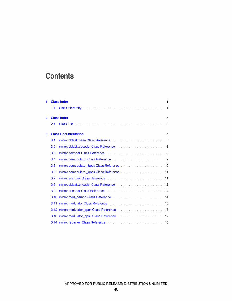
Contents
1 Class Index 1
1.1 Class Hierarchy . . . . . . . . . . . . . . . . . . . . . . . . . . . . . . 1
2 Class Index 3
2.1 Class List . . . . . . . . . . . . . . . . . . . . . . . . . . . . . . . . . 3
3 Class Documentation 5
3.1 mimo::dblast::base Class Reference . . . . . . . . . . . . . . . . . . . 5
3.2 mimo::dblast::decoder Class Reference . . . . . . . . . . . . . . . . . 6
3.3 mimo::decoder Class Reference . . . . . . . . . . . . . . . . . . . . . 8
3.4 mimo::demodulator Class Reference . . . . . . . . . . . . . . . . . . . 9
3.5 mimo::demodulator_bpsk Class Reference . . . . . . . . . . . . . . . . 10
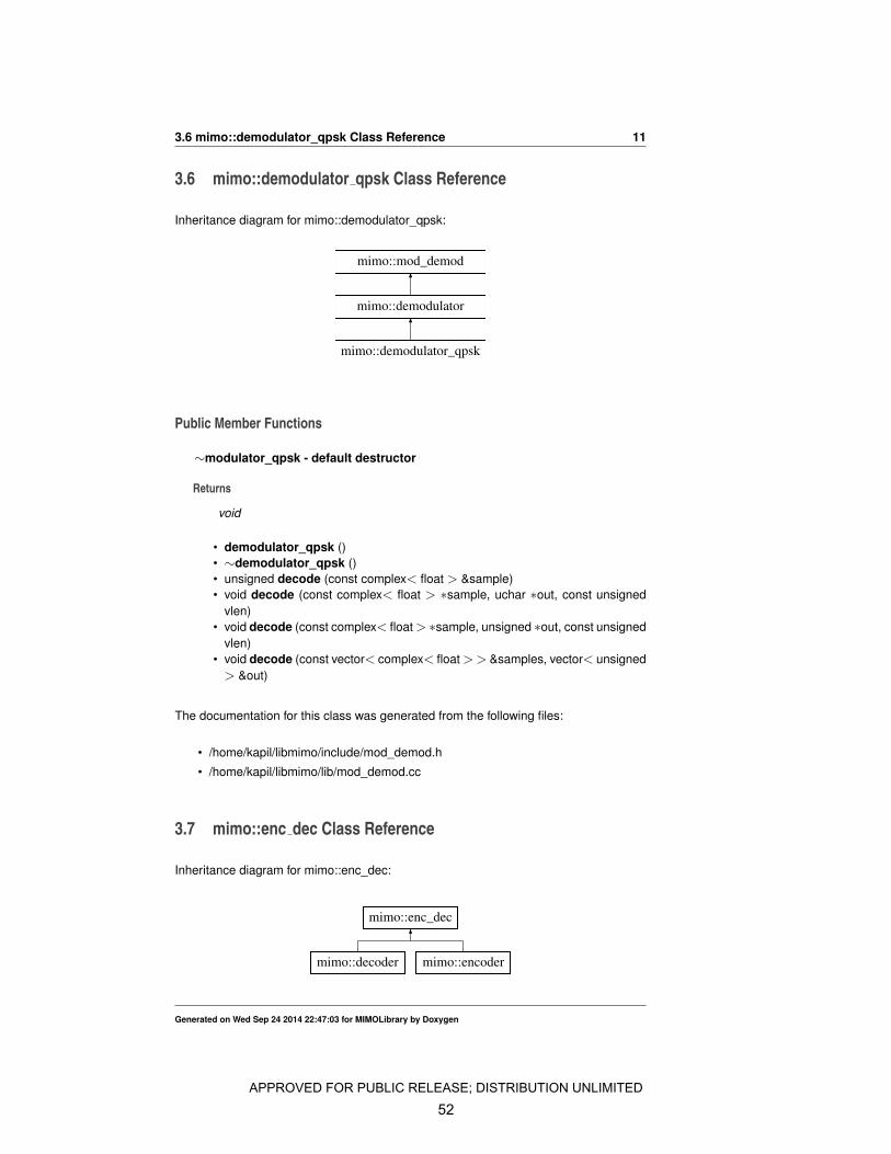
3.6 mimo::demodulator_qpsk Class Reference . . . . . . . . . . . . . . . . 11
3.7 mimo::enc_dec Class Reference . . . . . . . . . . . . . . . . . . . . . 11
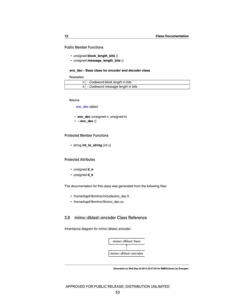
3.8 mimo::dblast::encoder Class Reference . . . . . . . . . . . . . . . . . 12
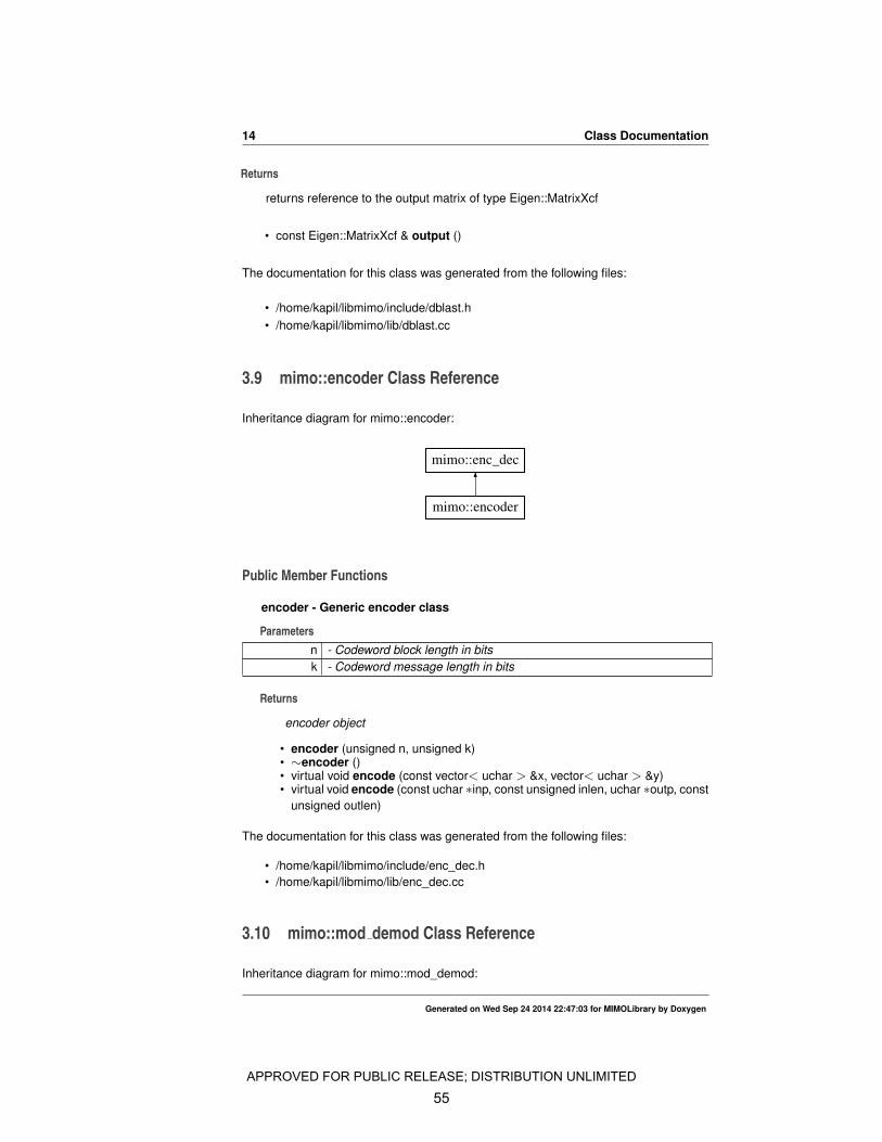
3.9 mimo::encoder Class Reference . . . . . . . . . . . . . . . . . . . . . 14
3.10 mimo::mod_demod Class Reference . . . . . . . . . . . . . . . . . . . 14
3.11 mimo::modulator Class Reference . . . . . . . . . . . . . . . . . . . . 15
3.12 mimo::modulator_bpsk Class Reference . . . . . . . . . . . . . . . . . 16
3.13 mimo::modulator_qpsk Class Reference . . . . . . . . . . . . . . . . . 17
3.14 mimo::repacker Class Reference . . . . . . . . . . . . . . . . . . . . . 18
APPROVED FOR PUBLIC RELEASE; DISTRIBUTION UNLIMITED
40

APPROVED FOR PUBLIC RELEASE; DISTRIBUTION UNLIMITED
41
Chapter 1
Class Index
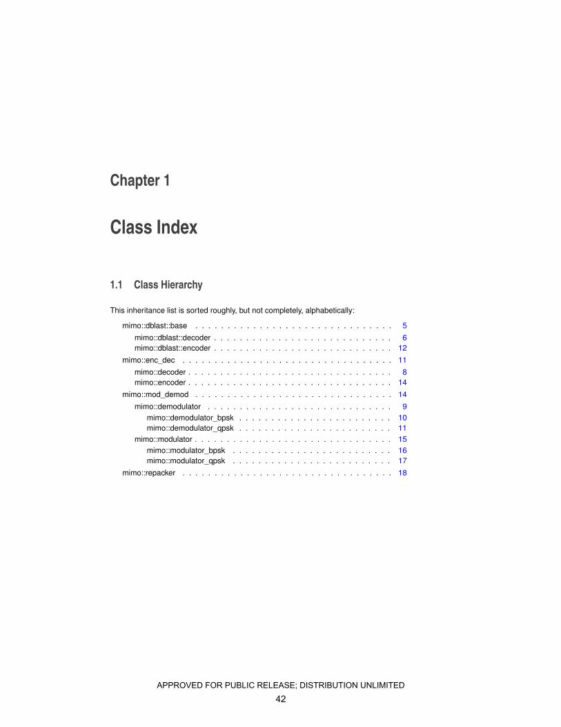
1.1 Class Hierarchy
This inheritance list is sorted roughly, but not completely, alphabetically:
mimo::dblast::base . . . . . . . . . . . . . . . . . . . . . . . . . . . . . . . 5
mimo::dblast::decoder . . . . . . . . . . . . . . . . . . . . . . . . . . . . 6mimo::dblast::encoder . . . . . . . . . . . . . . . . . . . . . . . . . . . . 12
mimo::enc_dec . . . . . . . . . . . . . . . . . . . . . . . . . . . . . . . . . 11
mimo::decoder . . . . . . . . . . . . . . . . . . . . . . . . . . . . . . . . 8mimo::encoder . . . . . . . . . . . . . . . . . . . . . . . . . . . . . . . . 14
mimo::mod_demod . . . . . . . . . . . . . . . . . . . . . . . . . . . . . . . 14
mimo::demodulator . . . . . . . . . . . . . . . . . . . . . . . . . . . . . 9mimo::demodulator_bpsk . . . . . . . . . . . . . . . . . . . . . . . . 10mimo::demodulator_qpsk . . . . . . . . . . . . . . . . . . . . . . . . 11
mimo::modulator . . . . . . . . . . . . . . . . . . . . . . . . . . . . . . . 15mimo::modulator_bpsk . . . . . . . . . . . . . . . . . . . . . . . . . 16mimo::modulator_qpsk . . . . . . . . . . . . . . . . . . . . . . . . . 17
mimo::repacker . . . . . . . . . . . . . . . . . . . . . . . . . . . . . . . . . 18
APPROVED FOR PUBLIC RELEASE; DISTRIBUTION UNLIMITED
42

2 Class Index
Generated on Wed Sep 24 2014 22:47:03 for MIMOLibrary by Doxygen
APPROVED FOR PUBLIC RELEASE; DISTRIBUTION UNLIMITED
43
Chapter 2
Class Index
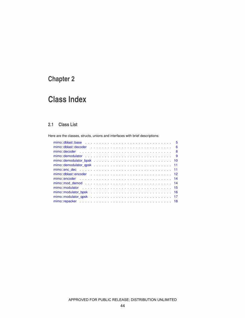
2.1 Class List
Here are the classes, structs, unions and interfaces with brief descriptions:
mimo::dblast::base . . . . . . . . . . . . . . . . . . . . . . . . . . . . . . . 5mimo::dblast::decoder . . . . . . . . . . . . . . . . . . . . . . . . . . . . . 6mimo::decoder . . . . . . . . . . . . . . . . . . . . . . . . . . . . . . . . . 8mimo::demodulator . . . . . . . . . . . . . . . . . . . . . . . . . . . . . . . 9mimo::demodulator_bpsk . . . . . . . . . . . . . . . . . . . . . . . . . . . . 10mimo::demodulator_qpsk . . . . . . . . . . . . . . . . . . . . . . . . . . . . 11mimo::enc_dec . . . . . . . . . . . . . . . . . . . . . . . . . . . . . . . . . 11mimo::dblast::encoder . . . . . . . . . . . . . . . . . . . . . . . . . . . . . 12mimo::encoder . . . . . . . . . . . . . . . . . . . . . . . . . . . . . . . . . 14mimo::mod_demod . . . . . . . . . . . . . . . . . . . . . . . . . . . . . . . 14mimo::modulator . . . . . . . . . . . . . . . . . . . . . . . . . . . . . . . . 15mimo::modulator_bpsk . . . . . . . . . . . . . . . . . . . . . . . . . . . . . 16mimo::modulator_qpsk . . . . . . . . . . . . . . . . . . . . . . . . . . . . . 17mimo::repacker . . . . . . . . . . . . . . . . . . . . . . . . . . . . . . . . . 18
APPROVED FOR PUBLIC RELEASE; DISTRIBUTION UNLIMITED
44

4 Class Index
Generated on Wed Sep 24 2014 22:47:03 for MIMOLibrary by Doxygen
APPROVED FOR PUBLIC RELEASE; DISTRIBUTION UNLIMITED
45
Chapter 3
Class Documentation
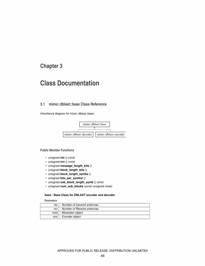
3.1 mimo::dblast::base Class Reference
Inheritance diagram for mimo::dblast::base:
mimo::dblast::base
mimo::dblast::decoder mimo::dblast::encoder
Public Member Functions
• unsigned ntx () const• unsigned nrx () const• unsigned message_length_bits ()• unsigned block_length_bits ()• unsigned block_length_symbs ()• unsigned bits_per_symbol ()• unsigned sub_block_length_symb () const• unsigned num_sub_blocks (const unsigned ncws)
base - Base Class for DBLAST encoder and decoder
Parametersntx - Number of transmit antennasnrx - Number of Receive antennas
mod - Modulator objectenc - Encoder object
APPROVED FOR PUBLIC RELEASE; DISTRIBUTION UNLIMITED
46
6 Class Documentation
Returns
base object
• base (const unsigned ntx, const unsigned nrx, mimo::modulator &mod, mimo-::encoder &enc)
Protected Member Functions
• void set_num_sub_block ()
Protected Attributes
• const unsigned d_ntx• const unsigned d_nrx• unsigned d_sbl• unsigned d_bls• mimo::repacker ∗ d_packer• mimo::modulator & d_mod• mimo::encoder & d_enc
∼base - default destructor
Returns
void
• ∼base ()• void check_args ()• void set_sbl ()
The documentation for this class was generated from the following files:
• /home/kapil/libmimo/include/dblast.h• /home/kapil/libmimo/lib/dblast.cc
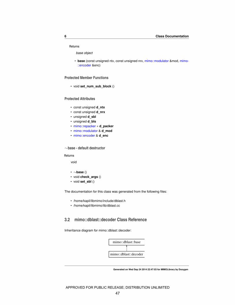
3.2 mimo::dblast::decoder Class Reference
Inheritance diagram for mimo::dblast::decoder:
mimo::dblast::decoder
mimo::dblast::base
Generated on Wed Sep 24 2014 22:47:03 for MIMOLibrary by Doxygen
APPROVED FOR PUBLIC RELEASE; DISTRIBUTION UNLIMITED
47
3.2 mimo::dblast::decoder Class Reference 7
Public Member Functions
decoder - DBLAST Decoder
Parametersntx - Number of transmit antennasnrx - Number of receive antennas
mod - Modulator objectdemod - Demodulator object
enc - Encoder Objectdenc - Decoder Object
ninput_cws - Number of input codewords in a block
Returns
decoder object
• decoder (const unsigned ntx, const unsigned nrx, mimo::modulator &mod,mimo::demodulator &demod, mimo::encoder &enc, mimo::decoder &denc,const unsigned ninput_cws)
set_ninput_cws - Allocates memory for use during encoding.
Parametersninput_cws - Number of input codewords
Returns
void
• void set_ninput_cws (const unsigned ncws)
decode - Decodes received DBLAST signal
Parametersinx - Matrix of dimenstion nsymb x ntx where nsymb is the number of sym-
bols time slots and ntx is the number of transmit antennasHhat - ntx nrx channel matrix
snr - Signal to noise ratio.
Returns
void
• void decode (const Eigen::MatrixXcf &inx, const Eigen::MatrixXcf &Hhat,const float &snr)
output_mat - Get decoded bits
Generated on Wed Sep 24 2014 22:47:03 for MIMOLibrary by Doxygen
APPROVED FOR PUBLIC RELEASE; DISTRIBUTION UNLIMITED
48
8 Class Documentation
Returns
Returns constant reference to Matrix of type mimo::MatrixXucharb. Each col-umn corresponds to a decoded codeword.
• const MatrixXuchar & output_mat () const
output - Returns the output generated by the decode function
Parametersout - Output vector to filled with decoded bits
Returns
void
• void output (vector< uchar > &out) const
∼decoder - default destructor
Returns
void
• ∼decoder ()
The documentation for this class was generated from the following files:
• /home/kapil/libmimo/include/dblast.h• /home/kapil/libmimo/lib/dblast.cc
3.3 mimo::decoder Class Reference
Inheritance diagram for mimo::decoder:
mimo::decoder
mimo::enc_dec
Public Member Functions
encoder - Generic decoder class
Parametersn - Codeword block length in bitsk - Codeword message length in bits
Generated on Wed Sep 24 2014 22:47:03 for MIMOLibrary by Doxygen
APPROVED FOR PUBLIC RELEASE; DISTRIBUTION UNLIMITED
49
3.4 mimo::demodulator Class Reference 9
Returns
decoder object
• decoder (unsigned n, unsigned k)• ∼decoder ()• virtual void decode (const vector< uchar > &x, vector< uchar > &y)• virtual void decode (const uchar ∗inp, const unsigned inlen, uchar ∗outp, const
unsigned outlen)
The documentation for this class was generated from the following files:
• /home/kapil/libmimo/include/enc_dec.h
• /home/kapil/libmimo/lib/enc_dec.cc
3.4 mimo::demodulator Class Reference
Inheritance diagram for mimo::demodulator:
mimo::demodulator
mimo::mod_demod
mimo::demodulator_bpsk mimo::demodulator_qpsk
Public Member Functions
∼modulator_qpsk - default destructor
Returns
void
• demodulator ()• demodulator (const vector< complex< float > > &constellation)• ∼demodulator ()• virtual unsigned decode (const complex< float > &sample)• virtual void decode (const complex< float > ∗sample, uchar ∗out, const un-
signed vlen)• virtual void decode (const complex< float > ∗sample, unsigned ∗out, const
unsigned vlen)• virtual void decode (const vector< complex< float > > &samples, vector<
unsigned > &out)
Generated on Wed Sep 24 2014 22:47:03 for MIMOLibrary by Doxygen
APPROVED FOR PUBLIC RELEASE; DISTRIBUTION UNLIMITED
50
10 Class Documentation
Protected Attributes
• vector< float > d_distances
• unsigned(demodulator::∗ decode_sample_ptr )(const complex< float > &)
The documentation for this class was generated from the following files:
• /home/kapil/libmimo/include/mod_demod.h
• /home/kapil/libmimo/lib/mod_demod.cc
3.5 mimo::demodulator bpsk Class Reference
Inheritance diagram for mimo::demodulator_bpsk:
mimo::demodulator_bpsk
mimo::demodulator
mimo::mod_demod
Public Member Functions
∼modulator_qpsk - default destructor
Returns
void
• demodulator_bpsk ()• ∼demodulator_bpsk ()• unsigned decode (const complex< float > &sample)• void decode (const complex< float > ∗sample, uchar ∗out, const unsigned
vlen)• void decode (const complex< float > ∗sample, unsigned ∗out, const unsigned
vlen)• void decode (const vector< complex< float >> &samples, vector< unsigned> &out)
The documentation for this class was generated from the following files:
• /home/kapil/libmimo/include/mod_demod.h
• /home/kapil/libmimo/lib/mod_demod.cc
Generated on Wed Sep 24 2014 22:47:03 for MIMOLibrary by Doxygen
APPROVED FOR PUBLIC RELEASE; DISTRIBUTION UNLIMITED
51
3.6 mimo::demodulator_qpsk Class Reference 11
3.6 mimo::demodulator qpsk Class Reference
Inheritance diagram for mimo::demodulator_qpsk:
mimo::demodulator_qpsk
mimo::demodulator
mimo::mod_demod
Public Member Functions
∼modulator_qpsk - default destructor
Returns
void
• demodulator_qpsk ()• ∼demodulator_qpsk ()• unsigned decode (const complex< float > &sample)• void decode (const complex< float > ∗sample, uchar ∗out, const unsigned
vlen)• void decode (const complex< float > ∗sample, unsigned ∗out, const unsigned
vlen)• void decode (const vector< complex< float >> &samples, vector< unsigned> &out)
The documentation for this class was generated from the following files:
• /home/kapil/libmimo/include/mod_demod.h
• /home/kapil/libmimo/lib/mod_demod.cc
3.7 mimo::enc dec Class Reference
Inheritance diagram for mimo::enc_dec:
mimo::enc_dec
mimo::decoder mimo::encoder
Generated on Wed Sep 24 2014 22:47:03 for MIMOLibrary by Doxygen
APPROVED FOR PUBLIC RELEASE; DISTRIBUTION UNLIMITED
52
12 Class Documentation
Public Member Functions
• unsigned block_length_bits ()• unsigned message_length_bits ()
enc_dec - Base class for encoder and decoder class
Parametersn - Codeword block length in bitsk - Codeword message length in bits
Returns
enc_dec object
• enc_dec (unsigned n, unsigned k)• ∼enc_dec ()
Protected Member Functions
• string int_to_string (int x)
Protected Attributes
• unsigned d_n
• unsigned d_k
The documentation for this class was generated from the following files:
• /home/kapil/libmimo/include/enc_dec.h
• /home/kapil/libmimo/lib/enc_dec.cc
3.8 mimo::dblast::encoder Class Reference
Inheritance diagram for mimo::dblast::encoder:
mimo::dblast::encoder
mimo::dblast::base
Generated on Wed Sep 24 2014 22:47:03 for MIMOLibrary by Doxygen
APPROVED FOR PUBLIC RELEASE; DISTRIBUTION UNLIMITED
53
3.8 mimo::dblast::encoder Class Reference 13
Public Member Functions
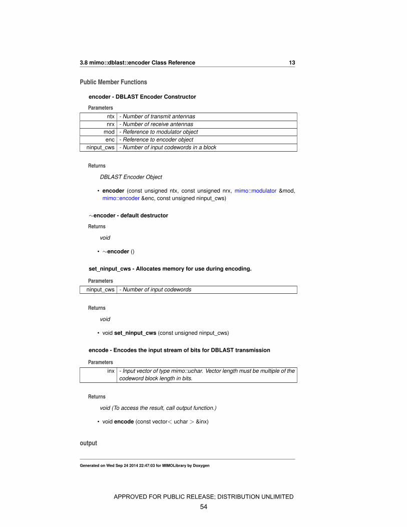
encoder - DBLAST Encoder Constructor
Parametersntx - Number of transmit antennasnrx - Number of receive antennas
mod - Reference to modulator objectenc - Reference to encoder object
ninput_cws - Number of input codewords in a block
Returns
DBLAST Encoder Object
• encoder (const unsigned ntx, const unsigned nrx, mimo::modulator &mod,mimo::encoder &enc, const unsigned ninput_cws)
∼encoder - default destructor
Returns
void
• ∼encoder ()
set_ninput_cws - Allocates memory for use during encoding.
Parametersninput_cws - Number of input codewords
Returns
void
• void set_ninput_cws (const unsigned ninput_cws)
encode - Encodes the input stream of bits for DBLAST transmission
Parametersinx - Input vector of type mimo::uchar. Vector length must be multiple of the
codeword block length in bits.
Returns
void (To access the result, call output function.)
• void encode (const vector< uchar > &inx)
output
Generated on Wed Sep 24 2014 22:47:03 for MIMOLibrary by Doxygen
APPROVED FOR PUBLIC RELEASE; DISTRIBUTION UNLIMITED
54
14 Class Documentation
Returns
returns reference to the output matrix of type Eigen::MatrixXcf
• const Eigen::MatrixXcf & output ()
The documentation for this class was generated from the following files:
• /home/kapil/libmimo/include/dblast.h• /home/kapil/libmimo/lib/dblast.cc
3.9 mimo::encoder Class Reference
Inheritance diagram for mimo::encoder:
mimo::encoder
mimo::enc_dec
Public Member Functions
encoder - Generic encoder class
Parametersn - Codeword block length in bitsk - Codeword message length in bits
Returns
encoder object
• encoder (unsigned n, unsigned k)• ∼encoder ()• virtual void encode (const vector< uchar > &x, vector< uchar > &y)• virtual void encode (const uchar ∗inp, const unsigned inlen, uchar ∗outp, const
unsigned outlen)
The documentation for this class was generated from the following files:
• /home/kapil/libmimo/include/enc_dec.h• /home/kapil/libmimo/lib/enc_dec.cc
3.10 mimo::mod demod Class Reference
Inheritance diagram for mimo::mod_demod:
Generated on Wed Sep 24 2014 22:47:03 for MIMOLibrary by Doxygen
APPROVED FOR PUBLIC RELEASE; DISTRIBUTION UNLIMITED
55
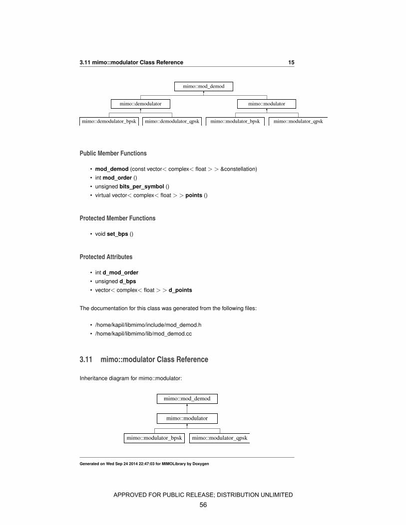
3.11 mimo::modulator Class Reference 15
mimo::mod_demod
mimo::demodulator mimo::modulator
mimo::demodulator_bpsk mimo::demodulator_qpsk mimo::modulator_bpsk mimo::modulator_qpsk
Public Member Functions
• mod_demod (const vector< complex< float > > &constellation)
• int mod_order ()
• unsigned bits_per_symbol ()
• virtual vector< complex< float > > points ()
Protected Member Functions
• void set_bps ()
Protected Attributes
• int d_mod_order• unsigned d_bps• vector< complex< float > > d_points
The documentation for this class was generated from the following files:
• /home/kapil/libmimo/include/mod_demod.h
• /home/kapil/libmimo/lib/mod_demod.cc
3.11 mimo::modulator Class Reference
Inheritance diagram for mimo::modulator:
mimo::modulator
mimo::mod_demod
mimo::modulator_bpsk mimo::modulator_qpsk
Generated on Wed Sep 24 2014 22:47:03 for MIMOLibrary by Doxygen
APPROVED FOR PUBLIC RELEASE; DISTRIBUTION UNLIMITED
56
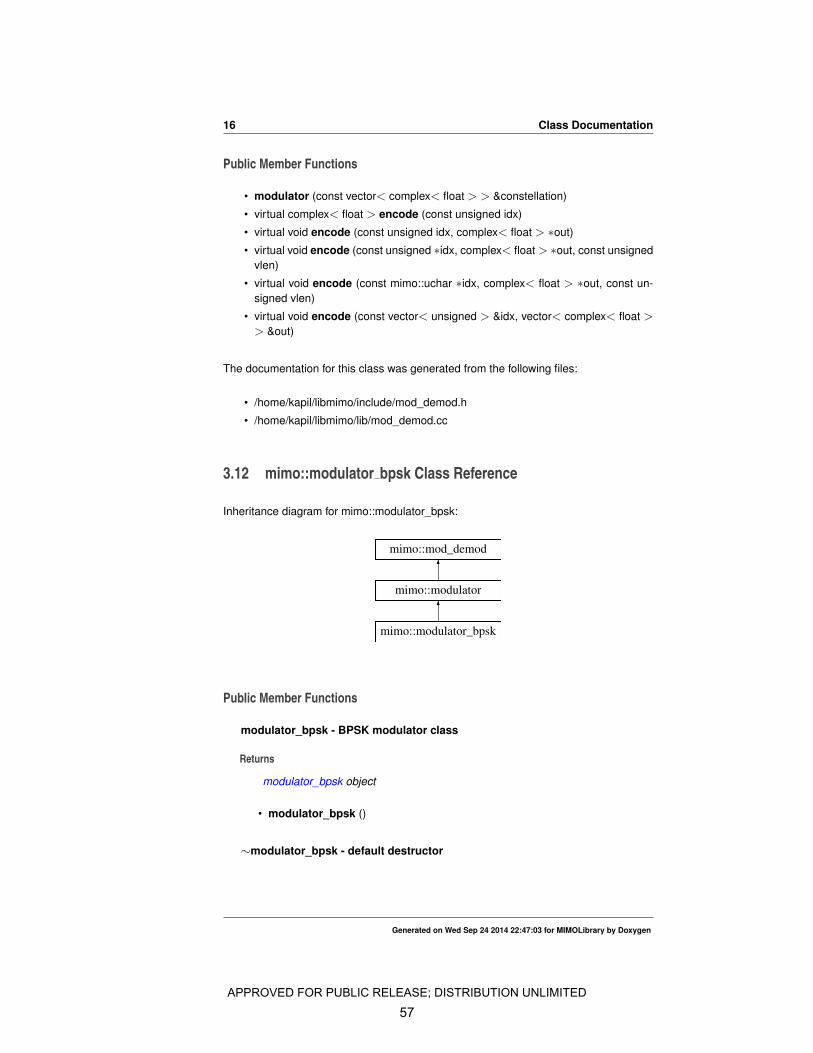
16 Class Documentation
Public Member Functions
• modulator (const vector< complex< float > > &constellation)
• virtual complex< float > encode (const unsigned idx)
• virtual void encode (const unsigned idx, complex< float > ∗out)
• virtual void encode (const unsigned ∗idx, complex< float > ∗out, const unsignedvlen)
• virtual void encode (const mimo::uchar ∗idx, complex< float > ∗out, const un-signed vlen)
• virtual void encode (const vector< unsigned > &idx, vector< complex< float >> &out)
The documentation for this class was generated from the following files:
• /home/kapil/libmimo/include/mod_demod.h
• /home/kapil/libmimo/lib/mod_demod.cc
3.12 mimo::modulator bpsk Class Reference
Inheritance diagram for mimo::modulator_bpsk:
mimo::modulator_bpsk
mimo::modulator
mimo::mod_demod
Public Member Functions
modulator_bpsk - BPSK modulator class
Returns
modulator_bpsk object
• modulator_bpsk ()
∼modulator_bpsk - default destructor
Generated on Wed Sep 24 2014 22:47:03 for MIMOLibrary by Doxygen
APPROVED FOR PUBLIC RELEASE; DISTRIBUTION UNLIMITED
57
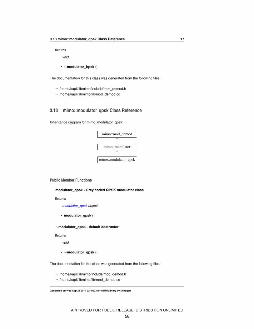
3.13 mimo::modulator_qpsk Class Reference 17
Returns
void
• ∼modulator_bpsk ()
The documentation for this class was generated from the following files:
• /home/kapil/libmimo/include/mod_demod.h
• /home/kapil/libmimo/lib/mod_demod.cc
3.13 mimo::modulator qpsk Class Reference
Inheritance diagram for mimo::modulator_qpsk:
mimo::modulator_qpsk
mimo::modulator
mimo::mod_demod
Public Member Functions
modulator_qpsk - Grey coded QPSK modulator class
Returns
modulator_qpsk object
• modulator_qpsk ()
∼modulator_qpsk - default destructor
Returns
void
• ∼modulator_qpsk ()
The documentation for this class was generated from the following files:
• /home/kapil/libmimo/include/mod_demod.h
• /home/kapil/libmimo/lib/mod_demod.cc
Generated on Wed Sep 24 2014 22:47:03 for MIMOLibrary by Doxygen
APPROVED FOR PUBLIC RELEASE; DISTRIBUTION UNLIMITED
58
18 Class Documentation
3.14 mimo::repacker Class Reference
Public Member Functions
• repacker (const unsigned k, const unsigned l)• void operator() (const uchar ∗inp, const unsigned inlen, uchar ∗outp, const un-
signed outlen)
The documentation for this class was generated from the following files:
• /home/kapil/libmimo/include/repacker.h• /home/kapil/libmimo/lib/repacker.cc
Generated on Wed Sep 24 2014 22:47:03 for MIMOLibrary by Doxygen
APPROVED FOR PUBLIC RELEASE; DISTRIBUTION UNLIMITED
59


![Printed Multi-Band MIMO Antenna Systems and Their ... · the diversity performance of the MIMO antenna system [3]. A ... Multiple-input-multiple-output (MIMO) antenna systems are](https://static.fdocuments.net/doc/165x107/601832972ff2e95336029d17/printed-multi-band-mimo-antenna-systems-and-their-the-diversity-performance.jpg)