Advanced Ignition Systems for Gasoline Direct Injection … · ADVANCED IGNITION SYSTEMS FOR...
28
Riccardo Scarcelli (PI), Anqi Zhang, James Sevik Argonne National Laboratory June 6, 2017 This presentation does not contain any proprietary, confidential, or otherwise restricted information Project ID: ACS084 DOE Technology Manager: Leo Breton ADVANCED IGNITION SYSTEMS FOR GASOLINE DIRECT INJECTION (GDI) ENGINES
Transcript of Advanced Ignition Systems for Gasoline Direct Injection … · ADVANCED IGNITION SYSTEMS FOR...

WE START WITH YES.
Riccardo Scarcelli (PI), Anqi Zhang, James SevikArgonne National Laboratory
June 6, 2017
This presentation does not contain any proprietary, confidential, or otherwise restricted information
Project ID: ACS084DOE Technology Manager: Leo Breton
ADVANCED IGNITION SYSTEMS FOR GASOLINE DIRECT INJECTION (GDI) ENGINES

OVERVIEWApproach Accomplishments Collaboration Future workRelevance
Budget Funding in FY16: $485k* Funding in FY17: $370k**
Timeline Project start: FY 2017 Project end: FY 2019 Percentage complete: 20%
This is a specific task of a large ANL research project addressing
the VTO Lab Call 2017“Towards Improved Understanding
and Modeling Capabilities for Advanced Combustion Engines”
BarriersLack of robust SI dilute combustion technology: Limited engine dilute operation Limited understanding of
advanced ignition mechanisms enabling SI dilute combustion
Limited availability of modeling tools for the development of advanced ignition systems
Main Partners Ford Motor Company Sandia National Laboratory Convergent Science, Inc. Esgee Technologies, Inc. Michigan Technological University* High-Efficiency GDI Engine Research (ended FY2016)
** Funds for FY17 reflect a reduced spending rate2

RELEVANCE
Current ignition technology in production is still based on conventional spark‒ Challenges exist at dilute and boosted operation‒ High required energy leads to durability issues‒ Spark models are not predictive under challenging conditions
Non-conventional ignition technologies are heading towards production‒ In-house development and optimization at suppliers‒ Absence of CFD models for engine optimization
Several promising technologies still at research stage‒ Limited understanding Slow development‒ Absence of CFD models for ignition/engine optimization
Approach Accomplishments Collaboration Future workRelevance
Ignition is a key enabler technology for highly dilute, efficient combustion
3

OBJECTIVES
Understand the fundamentals of ignition, in particular for non-conventional ignition technologies that show the potential to extend the engine dilution tolerance
Build novel ignition models and combustion modeling best-practices that allow accurately simulating the ignition process from advanced ignition systems under dilute operation
Demonstrate the efficiency increase potential of advanced ignitionsystems by understanding the trade-offs and interactions between theignition source and key engine features (flow, thermodynamics, etc.)
Approach Accomplishments Collaboration Future workRelevance
Improve basic knowledge and analysis of advanced ignition systems to enable dilute SI combustion
4

APPROACHAccomplishments Collaboration Future workRelevance Approach
CFD Modeling
Engine testing
LOW
HIGH
Understand Improve
Dilute Combustion
Potential
Ignition technologies
EVALUATIONImage:
BorgWarner
Image: TPS
Advanced diagnostics
VALIDATION
Image credits: SNL
Image credits: MTU
5

MILESTONES
Mo./Year Description Status
FY16 - High Efficiency GDI Engine Research with Emphasis on Ignition Systems
06/2016 Develop and validate conventional ignition model Completed
09/2016 Evaluate effect of laser ignition location on EGR dilute tolerance Completed
FY17 - Advanced Ignition Systems for GDI Engines
12/2016 Improve plasma characterization by leveraging advanced diagnostics Completed
03/2017 Use endoscope to evaluate ignition behavior at engine operation Completed
06/2017 Expand the ignition model to simulate non-conventional ignition On-Track
09/2017 Evaluate the effect of plasma composition on CFD ignition results On-Track
Accomplishments Collaboration Future workRelevance Approach
Modeling of non-equilibrium plasma initiated and compared to experimental observations
6

ACCOMPLISHMENTS FY16Collaboration Future workRelevance Approach Accomplishments
1. Predicts ignition success/failure
2. Captures plasma thermal properties
Detailed energy deposition (ED) model developed at ANL (selected for the 2016 US DRIVE Highlights)
Validated at quiescent conditions
Eulerian ED ignition model implemented in CONVERGE
and used with realistic inputs
1. Accurate energy release2. Line-shaped energy source3. Conjugate heat transfer4. Detailed chemistry
1
23
4
7

ACCOMPLISHMENTS FY17ED model evaluated at non-quiescent conditions
Collaboration Future workRelevance Approach Accomplishments
Default source motion settings in CONVERGE are simplistic Line source represented by a list of points Fixed number of points for the line source Even amount of energy for each point Source points can move with the flow No restrictions except max displacement Breakdown shock wave introduces a
strong perturbation of the channel shape
Spark channel elongationnot accurately described
Channel can easily detach from electrodes
Spatial energy depositionis essentially unrealistic
8

Schlieren images are a courtesy of S.Y. Lee (MTU)
CFD results qualitatively match Schlieren data from MTU for similar flow conditions
ACCOMPLISHMENTS FY17ED model developed in CONVERGE (UDFs) to describe spark channel elongation at non-quiescent conditions
Collaboration Future workRelevance Approach Accomplishments
1. Breakdown (BD) induces shock wave Points are hold right after BD2. Energy deposition affects the local flow Neighbor points move together3. Points are added when channel elongates to keep nicely shaped channel4. Energy is deposited evenly along the spark channel5. End points can freeze or keep moving along the electrodes
More work is planned on lean/dilute ignition and combustion in a combustion vessel (MTU) and DISI optical engine (SNL)
9

Multi-cycle CFD results show: Combustion metrics improve
when ignition point is protrudedITE increase up to 1% Lowest COVIMEP for middle
point (Protrusion = 2mm)
ACCOMPLISHMENTS FY17Simulation evaluated the effect of laser ignition location
Collaboration Future workRelevance Approach Accomplishments
FY2015 Results Experiments showed that laser ignition cannot match performance of conventional spark. Simulations showed that laser ignition flexibility (location) could be exploited (multi-point).FY2016 Results (Q4) Simulation and experiments evaluated effect of ignition location for single-point laser. A simplified ED model was used. Dedicated laser ED model has not been developed.
Engine results show: Combustion metrics improve
when ignition point is protrudedITE increase up to 0.5% Lowest COVIMEP for closest
point (Not protruded)
10
ACCOMPLISHMENTS FY17Collaboration Future workRelevance Approach Accomplishments
Misfires occur easier (i.e. at lower EGR) with high tumble and more protrusion This is a single-pulse laser Short duration Very sensitive to the local flow FDA/CD with laser are good at low tumble. ITE with laser always better than conventional Our laser ignition model is too simplistic and not predictive
Experiments evaluated the effect of laser ignition location
11

ACCOMPLISHMENTS FY17Improved understanding of non-equilibrium plasmas
Collaboration Future workRelevance Approach Accomplishments
Calorimetry experiments evaluated the transition LTPSSB* (I. Ekoto, ACS006)
Arcing occurs easier with more pulses. Thermal pre-conditioning claimed as the main cause
O* measurements complement thermal analysis Streamer characteristics (branching, etc.) are shown
Courtesy of I. Ekoto (SNL)
* I. Ekoto, ACS006
Arcing event (High V, low P)
Non-arcing event(Low V, High P)
Courtesy of C. Powell (ANL) Nano-pulse delivery can result in arcing event depending on voltage, density, composition, etc.
X-Ray diagnostics quantifies thermal properties (density)
Arcing (SSB*) shows low density. Non-arcing (LTP*) difficult to quantify
SNL-ANL coordinated effort to characterize non-equilibrium plasmas and provide data for qualitative/quantitative model validation
12

22.0
23.0
24.0
25.0
26.0
27.0
28.0
29.0
0 5 10 15 20 25
EGR
Dil T
ol @
3%
CO
V [%
]
Pulses [#]
1.0mm2.0mm Higher VoltageConventional
1500 rpm5.6 bar IMEPMBT Timing
65%V
70%V70%V85%V
85%V 85%V
Larger gap (Higher V)
ACCOMPLISHMENTS FY17Non-equilibrium plasma ignition evaluated at engine operation (1/2)
Collaboration Future workRelevance Approach Accomplishments
High Voltage and multiple pulses can extend dilution tolerance but increase the chance of arcing
Engine performance testing at stoichiometric, lean, and EGR dilute operation coupled with endoscope images for arcing detection
Cyclic variability of the arcing occurrence was observed
Arcing location can change from a cycle to the next
Arcing could happen but not be visible due to the electrodes
WEAK ARCING13

ACCOMPLISHMENTS FY17Non-equilibrium plasma ignition evaluated at engine operation (2/2)
Collaboration Future workRelevance Approach Accomplishments
High resolution endoscope images coupled with simultaneous measurement of voltage and current for arc detection
After the 1st occurrence of arc, keeps arcingin the same location
Consistent with other observations and withthe assumption of thermal pre-conditioning
Non-Arcing 1st Arc Arcing
14

ACCOMPLISHMENTS FY17Non-equilibrium plasma modeling initiated
Collaboration Future workRelevance Approach Accomplishments
Non-equilibrium plasma ignition systems aim to deliver the energy into gases in a volumetric fashion WITHOUT gas breakdown. Fuel-air mixture ignition is induced by excited species (radicals, electrons, etc.) at low temperatures.
log(t)10-3 sec10-6 sec10-9 sec
Time scale of one engine crank angle
Time scale of non-equilibrium plasma
dischargeTime scale of typical
engine cycle
Time scale challenge
Ignition source as combination of thermal energy and active species Separate plasma and flow/combustion time scales based on short deposition Requires detailed understanding of non-equilibrium plasma characteristics
Modeling strategy
VizGlow High-fidelity, self-consistent plasma code for non-equilibrium plasma Bulk gas heating and photoionization are modeled by the code 2D simulations are performed
15

1.07 bar12.0 ns
1.50 bar22.4 ns
1.70 bar29.5 ns
2.00 bar39.7 ns
2.30 bar50.0 ns
ACCOMPLISHMENTS FY17Non-equilibrium plasma modeling tentatively validated
Collaboration Future workRelevance Approach Accomplishments
1.07 bar 1.70 bar 2.30 bar
Top electrode: anode, bottom electrode: cathode
Pressure dependency behavior of the plasma are consistent with experimental observations
Increased ambient pressure leads to delayed plasma formation, reduced streamer thickness, higher tendency to branch
This is our SSBLTP transitionCourtesy of I. Ekoto (SNL)
16

Courtesy of I. Ekoto (SNL)
ACCOMPLISHMENTS FY17Non-equilibrium plasma characteristics investigated
Collaboration Future workRelevance Approach Accomplishments
Atomic O distribution1.07 bar
22 ns1.50 bar
50 ns1.70 bar
50 ns2.00 bar
50 ns2.30 bar
50 ns
Active species formation and local gas heating are two major factorsthat will impact ignition and combustion
1.07 bar22 ns
1.50 bar50 ns
1.70 bar50 ns
2.00 bar50 ns
2.30 bar50 ns
Temperature distributionTemp [K]
1000
343
672
O and Temperature distributions qualitatively capture experimental
observations at Sandia
O atom [ppm]
10000
0.1
5000
17

RESPONSE TO REVIEWER COMMENTSCollaboration Future workRelevance Approach Accomplishments
“...goal of 20% over a stoichiometric GDI engine with production spark is incorrect...” Acknowledged during Q&A discussion at last Annual Merit Review.
“…much of this experimental work has been done and reported. The reviewer questioned what more the project could hope to contribute…the focus should be on understanding the mechanism of ignition…and improving the process to gain dilution tolerance” This project has been re-scoped to provide in-depth understanding and build
advanced modeling tools. Such features can be of vital importance for industry to improve the dilute combustion process.
“…The modeling work supports the main experimental evaluation but cannot justify the project..” We will keep providing experimental evaluation of advanced ignition systems.
However, we believe that building proper understanding and reliable modeling tools is of high priority for industry.
“…More optical engine experiments should be conducted” No optical work is done at Argonne, but we have strategic partners (Sandia/MTU)
in that field. We also coupled performance testing with endoscope imaging to improve our experimental approach.
“Better guidance from an OEMs needed…Collaboration should not occur for the sake of collaboration” Please check our next slide on collaboration and coordination.
18

COLLABORATION AND COORDINATIONFuture workRelevance Approach Accomplishments Collaboration
…Not to forget ANL internal key collaborations…Advanced Photon Source (X-Ray diagnostics)
Distributed Energy Research Center (Laser ignition technology)
CoordinationRanking
GuidelinesIgnition systems SBIR/SBV programs
Experiments
OEM support Technical guidance
Ford Motor Company
Transient Plasma Systems, Inc.BorgWarnerPrinceton Optronics, Inc.Knite, Inc.
USCAR
Optical data for validationIgnition setup sharing
Coordination through USCAR
Optical data for validation
DiagnosticsSandia NL
Michigan Tech
Ignition model developmentBest-practices for GDI/CCV
Non-equilibrium plasma modelingCode validation and development
ModelingConvergent Science, Inc.
Egsee Technologies, Inc.
19
REMAINING CHALLENGES AND BARRIERSRelevance Approach Accomplishments Collaboration Future work
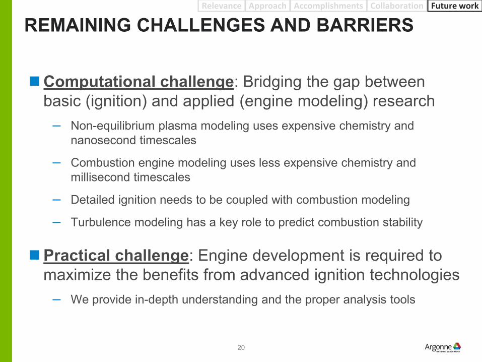
Computational challenge: Bridging the gap between basic (ignition) and applied (engine modeling) research
– Non-equilibrium plasma modeling uses expensive chemistry andnanosecond timescales
– Combustion engine modeling uses less expensive chemistry andmillisecond timescales
– Detailed ignition needs to be coupled with combustion modeling
– Turbulence modeling has a key role to predict combustion stability
Practical challenge: Engine development is required tomaximize the benefits from advanced ignition technologies
– We provide in-depth understanding and the proper analysis tools
20

PROPOSED FUTURE WORKRelevance Approach Accomplishments Collaboration
Use improved knowledge to expand current models (FY17)– Develop CFD engine codes to handle non-conventional ignition– Reduced plasma chemistry integrated with fuel chemistry
Build/validate advanced computational framework (FY18)– Comprehensive ignition model accounting for different plasma
technologies/characteristics– Couple advanced ignition models with CFD best-practices for the
simulation of GDI engines combustion and cyclic variability
Use modeling to identify potential development areas (FY19)– Basic analysis of discharge characteristics and geometry of the igniters– Interaction between ignition source and engine flow/thermodynamics
Future work
Any proposed future work is subject to change based on funding levels
21

SUMMARYRelevance Approach Accomplishments Collaboration Future work
Relevance Ignition is a key enabler technology for highly
dilute, efficient combustion CFD tools are not predictive when testing
conventional ignition at challenging conditions Limited or absent CFD models to handle non-
conventional ignition technologies
Approach Basic and applied research to understand
physics, build and apply models, demonstrate potential, and support development External and internal collaborations to leverage
core capabilities and key expertise
Technical accomplishments (1/2) Detailed energy deposition (ED) developed and
validated at non-quiescent conditions Effect of laser ignition location on engine
performance evaluated using both simulations and experiments
Technical accomplishments (2/2) Improved characterization of non-equilibrium
plasmas through coordinated effort at Argonne and Sandia using advanced diagnostics Non-equilibrium plasma ignition behavior
evaluated at engine operation Non-equilibrium plasma modeling initiated and
tentatively validated against experimental data from advanced diagnostics
Remaining barriers Convey the improved physical understanding of
non-conventional ignition systems (small timescales, complex chemistry) into a CFD engine tool (large timescales, reduced chemistry) to be practically used for development and optimization
Future work Build and validate comprehensive ignition and
combustion models Look at main interactions between engine
parameters (flow, thermodynamics) and ignition characteristics (discharge, geometry)
Advanced Ignition Systems for GDI Engines
22

www.anl.gov
BACKUP SLIDES

Technical Back-Up Slides
ED model development at non-quiescent conditionsTECHNICAL BACKUP SLIDES
Breakdown introduces strong flow perturbations Points frozen until shockwave is gone
Points do not move independently
from neighbors to avoid folding
New points added when channel
elongates to deliver nice shape
Consistent energy deposition
End points can freeze or keep moving along the electrodes
24

Technical Back-Up Slides
Simplified ED ignition model to simulate laser ignition– Spherical kernel shape– Size should be very small, but we are limited by the MIN mesh size (0.125 mm)– Energy deposition lasts nanosecond. Our assumption is 1 µs duration– These assumptions have never been validated against optical data– Simulations were run for 10 consecutive cycles at fixed BCs and spark timing– Low tumble configuration was simulated
Laser ignition modeling setupTECHNICAL BACKUP SLIDES
2000 RPM6bar IMEPLOW TUMBLEEGR =21%
Our assumption is that the model does not take into account the negative effect of flow (flame quenching) on misfires and severe partial burns
25

Technical Back-Up Slides
Laser ignition testing details (Low tumble)TECHNICAL BACKUP SLIDES
Engine test were performed at fixed IMEP (6 bar) and adjusting intake pressure Engine results are shown at MBT spark timing:
‒ Closest 39 °CA BTDC‒ Middle 40 °CA BTDC‒ Farthest 37 °CA BTDC Combustion is faster (consistent with simulations)
Conversely, simulations were run at fixed spark timing (40 °CA BTDC)
Protruding the ignition point progressively into the cylinder improves FDA/CD but increases the number of misfires/partial burns
This is the closest experiment to our simulations
Closest Middle Farthest
26

Technical Back-Up Slides
VizGlow setupTECHNICAL BACKUP SLIDES
Anode details
Cathode details
Anode
Cathode
Axisymmetric 2D domain
Plasma model highlights Electrostatic potential is computed using
Poisson’s equation O2-N2 plasma chemistry for high pressure
applications with 18 species: E, O2, O2*, O2a1, O2b1, O2+, O2-, O, O-, O4+, O2+N2, N2, N2a1, N2A, N2B, N2C, N2+, N4+
Photoionization and bulk energy are modeled
Boundary and initial conditions 5 mm gap between rounded electrode tips Mixture: 15.9% O2, 84.1% N2 @ 70K with
multiple pressure levels Experimental voltage profile applied to the
anode External circuit modeled with 100 ohm
resistance
Mesh configuration Mixed quad/tri mesh with 15 µm min size Uniform quad cells in the center gap Total cell count ~27,000
Experimental and smoothed voltage profile
Courtesy of I. Ekoto (SNL)27

Technical Back-Up Slides
VizGlow simulation detailsTECHNICAL BACKUP SLIDES
Atomic oxygen vs. excited state oxygen Qualitative comparison was carried out between
atomic oxygen (simulation) and excited state oxygen O* (experiment)
O* is not a direct output from the simulation, and three factors affect O* formation: concentration of ground state oxygen, concentration of electrons, and energy of electrons
High atomic oxygen concentration is found to reside at locations with high electron numbers and sufficient electron temperature
Identify Arcing in Simulation VizGlow is a code suitable for non-
equilibrium (bulk temperature is much lower than electron temperature) plasma
A characteristic dielectric relaxation time is tracked numerically during simulation
When arcing occurs, bulk temperature increases and the dielectric relaxation time drops to a very small value
Arcing occurs at 1.07 bar
Atomic Oxygen Electron Electron Temp.
28